US5603697A - Steering mechanism for catheters and methods for making same - Google Patents
Steering mechanism for catheters and methods for making sameDownload PDFInfo
- Publication number
- US5603697A US5603697AUS08/388,373US38837395AUS5603697AUS 5603697 AUS5603697 AUS 5603697AUS 38837395 AUS38837395 AUS 38837395AUS 5603697 AUS5603697 AUS 5603697A
- Authority
- US
- United States
- Prior art keywords
- tubular member
- transmission line
- catheter
- shield
- coaxial transmission
- Prior art date
- Legal status (The legal status is an assumption and is not a legal conclusion. Google has not performed a legal analysis and makes no representation as to the accuracy of the status listed.)
- Expired - Lifetime
Links
- 238000000034methodMethods0.000titleclaimsabstractdescription20
- 230000007246mechanismEffects0.000titledescription10
- 230000005540biological transmissionEffects0.000claimsabstractdescription58
- 238000002679ablationMethods0.000claimsabstractdescription19
- 239000004020conductorSubstances0.000claimsabstractdescription15
- 238000003780insertionMethods0.000claimsabstract2
- 230000037431insertionEffects0.000claimsabstract2
- 239000000463materialSubstances0.000claimsdescription14
- 230000005672electromagnetic fieldEffects0.000claimsdescription7
- 230000008878couplingEffects0.000claimsdescription4
- 238000010168coupling processMethods0.000claimsdescription4
- 238000005859coupling reactionMethods0.000claimsdescription4
- 239000011521glassSubstances0.000claimsdescription4
- 238000010438heat treatmentMethods0.000claimsdescription2
- 238000010276constructionMethods0.000abstractdescription8
- 238000005452bendingMethods0.000abstractdescription2
- 210000003813thumbAnatomy0.000description7
- 238000004861thermometryMethods0.000description6
- 239000003351stiffenerSubstances0.000description5
- 239000004809TeflonSubstances0.000description4
- 229920006362Teflon®Polymers0.000description4
- 238000005219brazingMethods0.000description4
- 239000003990capacitorSubstances0.000description4
- 230000000747cardiac effectEffects0.000description4
- 238000005476solderingMethods0.000description4
- 210000001519tissueAnatomy0.000description4
- 238000003466weldingMethods0.000description4
- 229920002614Polyether block amidePolymers0.000description3
- 238000013153catheter ablationMethods0.000description3
- 239000002184metalSubstances0.000description3
- 229910052751metalInorganic materials0.000description3
- 229920005989resinPolymers0.000description3
- 239000011347resinSubstances0.000description3
- 229910001220stainless steelInorganic materials0.000description3
- 239000010935stainless steelSubstances0.000description3
- 208000001871TachycardiaDiseases0.000description2
- 238000004873anchoringMethods0.000description2
- 229920001296polysiloxanePolymers0.000description2
- 230000006794tachycardiaEffects0.000description2
- RYGMFSIKBFXOCR-UHFFFAOYSA-NCopperChemical compound[Cu]RYGMFSIKBFXOCR-UHFFFAOYSA-N0.000description1
- 239000004593EpoxySubstances0.000description1
- 206010020843HyperthermiaDiseases0.000description1
- 206010028980NeoplasmDiseases0.000description1
- 239000002033PVDF binderSubstances0.000description1
- 239000004642PolyimideSubstances0.000description1
- 239000004721Polyphenylene oxideSubstances0.000description1
- 208000027418Wounds and injuryDiseases0.000description1
- 238000004026adhesive bondingMethods0.000description1
- 206010003119arrhythmiaDiseases0.000description1
- 230000003126arrythmogenic effectEffects0.000description1
- 239000008280bloodSubstances0.000description1
- 210000004369bloodAnatomy0.000description1
- 201000011510cancerDiseases0.000description1
- 230000035602clottingEffects0.000description1
- 239000011248coating agentSubstances0.000description1
- 238000000576coating methodMethods0.000description1
- 229910052802copperInorganic materials0.000description1
- 239000010949copperSubstances0.000description1
- 210000004351coronary vesselAnatomy0.000description1
- 238000002788crimpingMethods0.000description1
- 238000005520cutting processMethods0.000description1
- 230000006378damageEffects0.000description1
- 239000003989dielectric materialSubstances0.000description1
- 230000009977dual effectEffects0.000description1
- 230000000694effectsEffects0.000description1
- 210000001174endocardiumAnatomy0.000description1
- 239000000835fiberSubstances0.000description1
- 238000001914filtrationMethods0.000description1
- 239000012530fluidSubstances0.000description1
- 229920002313fluoropolymerPolymers0.000description1
- 239000004811fluoropolymerSubstances0.000description1
- PCHJSUWPFVWCPO-UHFFFAOYSA-NgoldChemical compound[Au]PCHJSUWPFVWCPO-UHFFFAOYSA-N0.000description1
- 239000010931goldSubstances0.000description1
- 229910052737goldInorganic materials0.000description1
- 210000005003heart tissueAnatomy0.000description1
- 230000036031hyperthermiaEffects0.000description1
- 238000001802infusionMethods0.000description1
- 230000003902lesionEffects0.000description1
- 231100000518lethalToxicity0.000description1
- 230000001665lethal effectEffects0.000description1
- 230000009347mechanical transmissionEffects0.000description1
- 239000000203mixtureSubstances0.000description1
- 229920000570polyetherPolymers0.000description1
- 229920001721polyimidePolymers0.000description1
- 229920000098polyolefinPolymers0.000description1
- 229920002981polyvinylidene fluoridePolymers0.000description1
- 238000005245sinteringMethods0.000description1
- 229910000679solderInorganic materials0.000description1
- 238000002560therapeutic procedureMethods0.000description1
Images


Classifications
- A—HUMAN NECESSITIES
- A61—MEDICAL OR VETERINARY SCIENCE; HYGIENE
- A61M—DEVICES FOR INTRODUCING MEDIA INTO, OR ONTO, THE BODY; DEVICES FOR TRANSDUCING BODY MEDIA OR FOR TAKING MEDIA FROM THE BODY; DEVICES FOR PRODUCING OR ENDING SLEEP OR STUPOR
- A61M25/00—Catheters; Hollow probes
- A61M25/01—Introducing, guiding, advancing, emplacing or holding catheters
- A61M25/0105—Steering means as part of the catheter or advancing means; Markers for positioning
- A61M25/0133—Tip steering devices
- A61M25/0144—Tip steering devices having flexible regions as a result of inner reinforcement means, e.g. struts or rods
- A—HUMAN NECESSITIES
- A61—MEDICAL OR VETERINARY SCIENCE; HYGIENE
- A61B—DIAGNOSIS; SURGERY; IDENTIFICATION
- A61B18/00—Surgical instruments, devices or methods for transferring non-mechanical forms of energy to or from the body
- A61B18/18—Surgical instruments, devices or methods for transferring non-mechanical forms of energy to or from the body by applying electromagnetic radiation, e.g. microwaves
- A61B18/1815—Surgical instruments, devices or methods for transferring non-mechanical forms of energy to or from the body by applying electromagnetic radiation, e.g. microwaves using microwaves
- A—HUMAN NECESSITIES
- A61—MEDICAL OR VETERINARY SCIENCE; HYGIENE
- A61M—DEVICES FOR INTRODUCING MEDIA INTO, OR ONTO, THE BODY; DEVICES FOR TRANSDUCING BODY MEDIA OR FOR TAKING MEDIA FROM THE BODY; DEVICES FOR PRODUCING OR ENDING SLEEP OR STUPOR
- A61M25/00—Catheters; Hollow probes
- A61M25/01—Introducing, guiding, advancing, emplacing or holding catheters
- A61M25/0105—Steering means as part of the catheter or advancing means; Markers for positioning
- A61M25/0133—Tip steering devices
- A61M25/0136—Handles therefor
- A—HUMAN NECESSITIES
- A61—MEDICAL OR VETERINARY SCIENCE; HYGIENE
- A61M—DEVICES FOR INTRODUCING MEDIA INTO, OR ONTO, THE BODY; DEVICES FOR TRANSDUCING BODY MEDIA OR FOR TAKING MEDIA FROM THE BODY; DEVICES FOR PRODUCING OR ENDING SLEEP OR STUPOR
- A61M25/00—Catheters; Hollow probes
- A61M25/01—Introducing, guiding, advancing, emplacing or holding catheters
- A61M25/0105—Steering means as part of the catheter or advancing means; Markers for positioning
- A61M25/0133—Tip steering devices
- A61M25/0147—Tip steering devices with movable mechanical means, e.g. pull wires
- A—HUMAN NECESSITIES
- A61—MEDICAL OR VETERINARY SCIENCE; HYGIENE
- A61B—DIAGNOSIS; SURGERY; IDENTIFICATION
- A61B18/00—Surgical instruments, devices or methods for transferring non-mechanical forms of energy to or from the body
- A61B18/18—Surgical instruments, devices or methods for transferring non-mechanical forms of energy to or from the body by applying electromagnetic radiation, e.g. microwaves
- A61B18/1815—Surgical instruments, devices or methods for transferring non-mechanical forms of energy to or from the body by applying electromagnetic radiation, e.g. microwaves using microwaves
- A61B2018/1861—Surgical instruments, devices or methods for transferring non-mechanical forms of energy to or from the body by applying electromagnetic radiation, e.g. microwaves using microwaves with an instrument inserted into a body lumen or cavity, e.g. a catheter
- A—HUMAN NECESSITIES
- A61—MEDICAL OR VETERINARY SCIENCE; HYGIENE
- A61M—DEVICES FOR INTRODUCING MEDIA INTO, OR ONTO, THE BODY; DEVICES FOR TRANSDUCING BODY MEDIA OR FOR TAKING MEDIA FROM THE BODY; DEVICES FOR PRODUCING OR ENDING SLEEP OR STUPOR
- A61M25/00—Catheters; Hollow probes
- A61M25/01—Introducing, guiding, advancing, emplacing or holding catheters
- A61M25/0105—Steering means as part of the catheter or advancing means; Markers for positioning
- A61M25/0133—Tip steering devices
- A61M25/0147—Tip steering devices with movable mechanical means, e.g. pull wires
- A61M2025/015—Details of the distal fixation of the movable mechanical means
Definitions
- the present inventionrelates generally to a steering mechanism for catheter systems.
- the described steering mechanismis particularly well suited for use in catheter systems that use electromagnetic energy transmitted over a coaxial transmission line to ablate internal bodily materials.
- Radio frequency (RF) energyis presently accepted as the preferred ablating energy source. Accordingly, a variety of RF catheters and power supplies are currently available to electrophysiologists. Radio frequency energy has several limitations including the rapid dissipation of energy in surface tissues resulting in shallow "burns" and failure to access deeper arrhythmogenic tissues. Another limitation is the risk of clot formation on the energy emitting electrodes. Such clots have an associated danger of causing potentially lethal strokes in the event that a clot is dislodged from the catheter. For these and other reasons, significant attention has been given recently to alternative ablative energy sources.
- Microwave frequency energyhas long been recognized as an effective energy source for heating of biological tissues and has seen use in such hyperthermia applications as cancer treatment and preheating of blood prior to infusions. Accordingly, in view of the drawbacks of the traditional catheter ablation techniques, there has recently been an interest in using microwave energy as an ablation energy source.
- microwave energyis that it is much easier to control and safer than direct current applications and it is capable of generating substantially larger lesions than RF catheters, which greatly simplifies the actual ablation procedures.
- the catheteris formed from a flexible tubular member adapted to be inserted into a vessel in the body of a patient.
- An elongated coaxial transmission lineis and received within a lumen in the flexible tubular member.
- the coaxial transmission lineincludes a center conductor, a shield and a dielectric that electrically insulates the center conductor from the shield.
- An antennais coupled to the center conductor of the coaxial transmission line.
- a shield terminationis secured to the shield portion of the coaxial transmission line.
- a steering wire that extends through a tube encapsulated in the flexible tubular memberis attached to the shield termination.
- a distal portion of the tubular memberhas a stiffness that is significantly less than the stiffness of the majority of the tubular member to facilitate bending during steering.
- the geometry of the shield terminationmay be varied greatly. In one preferred embodiment, it constitutes an annular member that permits the coaxial transmission line to pass there through.
- an elongated flexible tubular memberthat is sized suitably to be inserted into a vessel in the body of a patient is formed such that a first portion of the tubular member has a stiffness that is significantly less than the stiffness of the majority of the tubular member.
- a shield termination ringis secured to the distal end of a braided shield portion of the coaxial transmission line.
- One or more steering wiresare then attached to the shield termination ring.
- the coaxial transmission line and the steering wires assemblyis then inserted into the flexible tubular member as a unit. Thereafter a cap is secured to the distal end of the flexible tubular member to enclose the antenna.
- the first portion of the tubular memberis formed from a material having a first stiffness and the second portion (majority) of the tubular member is separately formed from a stiffer material.
- the first and second portions of the tubular memberare then heated to a glass point and bonded together at that state.
- FIG. 1is a diagrammatic view of an ablation catheter formed in accordance with one embodiment of the present invention.
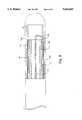
- FIG. 2is a diagrammatic partial cross sectional side view of the end portion of the ablation catheter illustrated in FIG. 1.
- FIG. 3is a diagrammatic cross sectional view of the ablation catheter illustrated in FIG. 1 taken along line 3--3 illustrating the multi-lumen flexible member and the components that pass through the various lumens.
- FIG. 4is a diagrammatic side view illustrating an arrangement for attaching a ring collar to a coaxial transmission line.
- FIG. 5is a partially broken away diagrammatic illustration of a handle transducer suitable for steering the catheter tip as it is positioned in the body of a patient.
- FIG. 6is a diagrammatic partial cross sectional side view of the end portion of an alternative embodiment of the present invention.
- FIG. 7is a diagrammatic cross sectional view illustrating a single-lumen flexible member and the components that pass there through.
- FIG. 8is a diagrammatic cross sectional side view illustrating the placement of a tuning capacitor used to facilitate impedance matching for the catheter system.
- FIG. 9is a diagrammatic side view of an alternative handle transducer embodiment suitable for steering the catheter tip as it is positioned in the body of a patient.
- the present inventionrelates generally to medical catheter systems. To facilitate description of the present invention, its application in a microwave ablation catheter system that uses a coaxial transmission line to transmit electromagnetic energy to an antenna mounted at the distal end of the catheter will be described.
- medical catheter systemstypically include an elongated catheter having a working member disposed near the distal tip of the catheter and a transmission line for actuating and/or powering the working member.
- the transmission linepasses through an elongated tubular member.
- a handleis typically positioned near the proximal end of the catheter to permit the user (typically a doctor) to control the catheter.
- a connectoris typically provided at the proximal end of the catheter to facilitate connection to a base unit that powers the working member.
- the working memberis the antenna
- the baseincludes a microwave power supply
- the transmission lineis a coaxial cable.
- the catheter 50includes outer tubing 51, a coaxial microwave transmission line 53, a helical antenna 56, at least one stiffening wire 58, at least one steering wire 66, a plurality of electrode wires 61-64, thermometry elements 65, electrodes 67 and a connector 71.
- the outer tubing 51may be made of any suitable material such as medical grade polyolefins, polyether, polyimides, fluoropolymers, or polyvinylidene fluoride. Further, PEBAX resins from Autochem of Germany have been used with success for the outer tubing of the body of the catheter. However, Teflon type products are preferred for the tip.
- the connector 71couples the transmission line 53 to an external power supply.
- the wave guideshould be a coaxial cable. Therefore, a coaxial wave guide is selected that is suitable for transmitting microwave energy.
- a suitable wave guideis the CW4050-3050P coaxial cable supplied by Cooner of Chatsworth (Calif).
- the diameter of the coaxial transmission line 53will vary depending upon the needs of a particular system. However, generally, the larger the diameter, the better the microwave transmission characteristics will be.
- the catheter diameteris typically limited to approximately 71/2 French (approximately 2.5 mm in diameter). In such a system, a wave guide that is approximately one meter long and has a diameter of 72 thousandths of an inch (1.8 mm) works well.
- a metal collaris affixed to the distal end of the braided shield of the coaxial transmission line is used as a shield termination 130. The metal ring is also used to anchor steering wires 66 which may be used to bend the tip of the catheter to facilitate steering.
- An antenna 56is provided at the distal end of the transmission line.
- a helical coil type antennahaving a total length (i.e. length of the wire along the coil as opposed to the longitudinal length of the coil) equal to either one eighth or one quarter of the wavelength of the transmitted microwave energy (or a multiple thereof) has been found to work particularly well when the goal is to develop a strong field to the side of the antenna, which is desirable for certain applications.
- This antenna configurationalso exhibits particularly good coupling to the transmission line. In view of this characteristic, the optimal actual length of such an antenna will vary in accordance with the selected frequency.
- the characteristics of the helical coil type antennaare the result of a variety of characteristics including shield (ground plane) to antenna gap, coil pitch, wire size, wire geometry and coil diameter.
- shieldground plane
- the actual antenna geometrycan be varied widely in accordance with the type of ablation that is desired for a particular application.
- the helical antenna shownis particularly good at developing a strong electromagnetic field to the side of the catheter tip.
- a straight antenna tip that extends slightly beyond a shieldmay be more effective at developing fields that extend from the distal end of the catheter.
- a series of electrodes 67may be provided near the tip of the catheter to monitor the patient's condition and/or the nature of the ablation process.
- the information obtained from the electrodes 67is transmitted through the power supply to external electronics. Filtering of the signal may be provided as necessary.
- some of the external electronicscould be incorporated into the power supply and/or the power supply could use information obtained from the electrodes in its control scheme.
- thermometry elements 65may take the form of thermocouple wires, fiber optic sensor cables or any other suitable thermometry devices.
- the catheter tip 100is encased within an insulating shell 102 formed from a material with a low dielectric constant such as silicone or Teflon.
- the shell 102insulates the antenna 56 to avoid the charring and tissue destruction effects that are commonly experienced with exposed (uninsulated) catheter tips. Details of suitable antennas and suitable catheter tip constructions are described in the related application referenced above.
- the outer tubing 51is formed from a suitable medical grade material.
- PEBAX resinworks well.
- the majority of the catheteris formed from a relatively stiff resin mixture.
- durometer readings in the range of 30-70 shore D hardnesswork well.
- material having durometer stiffness of 62 shore D hardnesshas been found to work well.
- An end portion 105 of the outer tubing 51is formed such that its stiffness is less than that of the main portion of the outer tubing. The softer end portion 105 is the portion of the catheter that will bend during steering.
- durometer readings in the range of 30 to 55 shore D hardness, as for example 45have been found to work well to provide enough stiffness so that the catheter may be inserted into coronary vessels, yet flexible enough to follow the tortuous path required in order to position the catheter in the heart for treatment of tachycardia and cardiac disrhythmia.
- the actual length of the end portion 105may vary in accordance with the requirements of a particular catheter. However, generally lengths in the range of two to eight centimeters has been found to work well for cardiac applications.
- the coaxial transmission line 53includes a center conductor 114, a dielectric support portion 116 that surrounds and insulates the center conductor and a braided shield portion 117.
- the shield 117terminates proximally of the antenna.
- the center conductoris connected directly to the antenna.
- the dielectric support portion 116 of the coaxial transmission linemay extend beyond the point where the braided shield is attached to the shield termination so that it extends coaxially through the entire antenna coil and into a supporting recess in a dielectric plug positioned at the distal tip of the shell 102.
- a metallic collar that fits around the dielectric support portion 116 of the coaxial transmission lineis soldered to the distal end of the shield in order to form a shield termination 130.
- the shield terminationserves as an electromagnetic shield for the electronics.
- the shield terminationmay be formed of stainless steel for welding attachment or plated with a suitable material for brazing or soldering.
- the braided shieldmay be formed from small, silver-plated copper wires. When such a coaxial transmission line is used, silver solder has been found to work well to couple the shield to the shield termination ring 130.
- the steering wire 66may be formed from any suitable material.
- stainless steel spring wirehas been found to work well.
- the steering wiresare attached to the shield termination 130. Since the steering wire 66 will typically be pulled back and forth relatively often during introduction of the catheter into the body of a patient, it is important that the attachment between the steering wire and the shield termination be quite good. A wide variety of soldering, welding, brazing, sintering processes may be used to attach these components. By way of example, a gold weld has been found to work well. Since the overall diameter of the catheter is strictly limited and it is desirable to have the largest diameter coaxial cable that is possible, the steering wires 66 are preferably quite small in diameter.
- steering wires having a diameter of approximately 6-10 milshave been found to work well.
- Teflonworks well as a coating material.
- the shield termination 130is simply an annular ring.
- different geometriesmay be used without departing from the spirit or scope of the invention.
- a wide variety of other shield terminationsmay be used as well for both anchoring the steering wires and terminating the braided shield.
- the geometry of the shield terminationmay be varied and configured in a wide variety of manners in order to influence the shape of the electromagnetic field presented by the antenna.
- the tubular member 51has an elongated central lumen 52, a plurality of stiffener/steering lumens 57, and a plurality of elongated component lumens 59.
- the central lumen 52is sized to receive the coaxial transmission line 53.
- the stiffener/steering lumens 57receive stiffener wires 58 and steering wires 66, respectively.
- two opposing stiffening wires 58are provided and two opposing steering wires 66 are provided.
- the other various wires(such as the electrode and thermometry wires) may be run through the components lumen 59.
- one of the stiffeners/steering lumens or one of the component lumens 59may be used to pass a fluid suitable for inflating the balloon(s).
- tubular memberscan be fabricated in a wide variety of ways as will be apparent to those skilled in the art.
- medical grade tubingcan be drawn in any conventional manner.
- the stiffer tubing and the softer tubingare formed separately and cut to their desired length.
- the stiffer tubingmay make up the bulk of the catheter length (which will of course be dictated by the intended application), while the softer tubing may be closer to two to eight centimeters.
- typical lengths for coronary applicationsare on the order of 100-130 centimeters.
- theymay be placed on a jig that preserves the lumen integrity and heated to a temperature just past the glass point.
- bonding temperaturesof approximately 300° F are appropriate. With the tubing in such a state, the stiffer and softer tubes may be pressed together to form a thermal bond that, when cooled, is extremely strong.
- the electronic wiring that is directly or indirectly coupled to the shield terminationmay be inserted as a complete assembly.
- the antenna 56is secured to the center conductor of the coaxial transmission line and the shield termination 130 is secured to the shield as described above.
- the steering wires 66are welded to the shield termination, and the entire assembly may be inserted as a unit into the appropriate lumens in the tubing 51.
- a stiffener collar 180may be positioned at the junction of the stiff and soft tubings 51,102 as illustrated in FIG. 4. The stiffening collar may then be used to anchor the stiffening wires 58. Like the steering wires, the stiffening wires may be formed from stainless steel spring wire, although frequently they may be slightly larger in diameter if the design permits.
- the ring collar 130has an inner diameter that is similar to the diameter of the tubular member's central lumen 52.
- the ring collaris positioned to abut against the distal end of the portion of the soft tubular member 105 located between the central lumen 52 and the lumens for the steering wire(s).
- an epoxy or other suitable materialcan be used to further set and secure the collar ring in place.
- the handle 140includes a housing 141, a deflecting slide 142, a locking mechanism 143, housing caps 144, a strain relief 145, and an electrical connector 71.
- the deflecting slide 142is coupled to the proximal end of the steering wire, allowing the user to pull on the steering wire via the deflecting slide.
- the locking mechanism 143can be activated to hold the deflecting slide 142 in place.
- only one steering wireis used. However, in alternative embodiments, two or more steering wires may be used.
- a spring loaded bobbinmay be used to drive dual steering wires by wrapping one wire clockwise and one counterclockwise on the bobbin and coupling one of the wires to the deflecting slide.
- An LED 148may also be provided to show when the ablation catheter is in use. Additionally, the outer surface of the housing 141 may be knurled to facilitate better gripping.
- shield termination 130is coupled to the shield portion 117 of the coaxial transmission line 53.
- the shield termination 130has an enlarged head 132 at its distal end.
- the various electrodes and metallic wiresare located proximal of the shield termination head for protection from the strong electromagnetic fields generated during use.
- the shield terminationserves as an electromagnetic shield for the electronics.
- the catheter tip 100is encased within an insulating shell 102 formed from a dielectric material such as silicone or Teflon.
- the shield termination 130extends proximally beyond the dielectric shell 102 to make a good connection with the shield 117 which anchors the catheter transmission line.
- the connectioncan be made using any suitable connection technique such as soldering, brazing or crimping.
- the shield terminationalso includes an enlarged anchor portion 134 that mates with the proximal end of the shell to secure the shell in place.
- the anchor and head portions of the shield termination 130cooperate to form a bobbin like structure having an opening 135 that receives the ground coil 108.
- the distal end of the thermometry element 65(not shown) are positioned behind the head portion 132 of the shield termination.
- the electrodes 67are positioned proximally relative to the shell 102.
- stiffening/steering wires 58are also attached to proximal portion of the shield termination by any suitable connection technique such as welding, brazing, soldering or adhesive bonding.
- any suitable connection techniquesuch as welding, brazing, soldering or adhesive bonding.
- the welding technique described aboveworks well.
- the reason for the positioning of the thermocouple, the electrodes and wire elements behind the shieldis to prevent their interference with the electromagnetic field and vice versa.
- a slidable thrust plate 120is provided between the proximal end of the antenna coil 56 and the shield termination head 132.
- the thrust plate 120is driven by a balloon actuator 123 that is located between the thrust plate and the face 133 of the shield termination.
- the shield termination 130acts as a surface against which the balloon actuator 123 may push in order to regulate the position of the thrust plate.
- the balloon actuator 123is fed by a feed tube 125.
- a slider 137is provided distal of the thrust plate and serves to balance the thrust plate 120 so that it moves evenly in an orientation that is substantially perpendicular to the longitudinal axis of the catheter. More specifically, the slider is secured to the thrust plate and is closely journaled around the dielectric support 116 to insure that the thrust plate 120 does not wobble as it translates. Electrical properties of the slide 137 may be selected appropriately based upon the needs of a particular catheter.
- the catheter 50aincludes an outer tubing 51a having a single lumen which receives coaxial microwave transmission line 53, a single steering wire 66a which is received with in a steering wire support tube 84, thermometry elements 65a and electrode wires 61a-64a.
- a tunable capacitor 200is also provided to electrically facilitate the adjustment of the antenna's impedance.
- the tunable capacitormay take the form of a Veractor diode.
- the Veractor diodeis coupled between the antenna 56 and the shield termination 130. Tuning may be accomplished by applying s D.C. tuning voltage to the center conductor.
- the applications referenced abovedisclose a number of methods of tuning the catheter system in order to facilitate impedance matching.
- the method described herein which incorporates a tunable capacitormay be used either standing alone or in conjunction with other tuning systems such as those described in the above referenced applications.
- the handle 240includes a tubular housing 241, a slider 243 that is slidable relative to the housing, an electrical connector 244 that plugs the proximal end of the housing and a distal cap 245.
- the catheter 50is received into the handle through a concentric bore 246 in the distal cap 245.
- the distal capis then used to anchor the catheter's outer tubing 51.
- the slider 243is used to anchor steering wire 66 and thus movements of the slider relative to the housing effectively pull or push the steering wire causing corresponding deflections of the catheter tip as described above.
- the electrical components including the transmission line 53pass through the tubular housing to the electrical connector 244.
- the connector 244is preferably adapted for connection to wiring from a power supply.
- the housing 241is substantially tubular in shape and has a longitudinally extending slot 247 on one surface.
- the slider 243includes a substantially tubular guide 251 that is slidably received within the housing 24 1, a thumb knob 254 that is positioned external to the housing and a connecting post 256 that extends through the slot 247 to couples the thumb knob and the slider together.
- a pair of pegs 248are also coupled to the thumb knob 254 such that they extend into the slot 247.
- the pegsare positioned longitudinally on opposite sides of post 256 and cooperate with the proximal and distal ends of the slot 247 to limit the movement of the thumb knob.
- An anchor ring 249is provided on the slider and serves as an anchor point for the steering wire. That is, the steering wire is attached to the anchor ring. With this construction, the thumb knob may be used to push and pull the steering wire back and forth and the pegs 248 effectively limit the movement of the steering wires.
- a locking thumb screw 261may also be provided that extends through and is threadably engaged with one wall of the housing such that it can contact the guide 251.
- the thumb screw 261may be used by the operator to lock the slider (and thus the steering wire) in place.
- an LED 264is mounted on the surface of the housing 241 such that it is readily visible by the operator. As described above, the LED may be used to indicate when the ablation catheter is in use. That is, when the power is on.
- the described ring structure in conjunction with the softened end portion of the cathetercan be applied to various other catheters such as mechanical atherectomy devices and other catheters that utilize mechanical transmission lines to modulate a working component.
- One advantage of the ring structureis that it permits the transmission line to pass the center thereof.
Landscapes
- Health & Medical Sciences (AREA)
- Life Sciences & Earth Sciences (AREA)
- Engineering & Computer Science (AREA)
- General Health & Medical Sciences (AREA)
- Veterinary Medicine (AREA)
- Biomedical Technology (AREA)
- Heart & Thoracic Surgery (AREA)
- Public Health (AREA)
- Animal Behavior & Ethology (AREA)
- Surgery (AREA)
- Anesthesiology (AREA)
- Hematology (AREA)
- Pulmonology (AREA)
- Biophysics (AREA)
- Physics & Mathematics (AREA)
- Electromagnetism (AREA)
- Nuclear Medicine, Radiotherapy & Molecular Imaging (AREA)
- Otolaryngology (AREA)
- Medical Informatics (AREA)
- Molecular Biology (AREA)
- Mechanical Engineering (AREA)
- Surgical Instruments (AREA)
Abstract
Description
Claims (16)
Priority Applications (1)
| Application Number | Priority Date | Filing Date | Title |
|---|---|---|---|
| US08/388,373US5603697A (en) | 1995-02-14 | 1995-02-14 | Steering mechanism for catheters and methods for making same |
Applications Claiming Priority (1)
| Application Number | Priority Date | Filing Date | Title |
|---|---|---|---|
| US08/388,373US5603697A (en) | 1995-02-14 | 1995-02-14 | Steering mechanism for catheters and methods for making same |
Publications (1)
| Publication Number | Publication Date |
|---|---|
| US5603697Atrue US5603697A (en) | 1997-02-18 |
Family
ID=23533850
Family Applications (1)
| Application Number | Title | Priority Date | Filing Date |
|---|---|---|---|
| US08/388,373Expired - LifetimeUS5603697A (en) | 1995-02-14 | 1995-02-14 | Steering mechanism for catheters and methods for making same |
Country Status (1)
| Country | Link |
|---|---|
| US (1) | US5603697A (en) |
Cited By (109)
| Publication number | Priority date | Publication date | Assignee | Title |
|---|---|---|---|---|
| US5755760A (en)* | 1996-03-11 | 1998-05-26 | Medtronic, Inc. | Deflectable catheter |
| US6045530A (en)* | 1998-10-14 | 2000-04-04 | Heyer-Schulte Neurocare Inc. | Adjustable angle catheter |
| US6090104A (en)* | 1995-06-07 | 2000-07-18 | Cordis Webster, Inc. | Catheter with a spirally wound flat ribbon electrode |
| EP1009467A4 (en)* | 1997-02-19 | 2001-07-25 | Condado Med Devices Corp | Multi-purpose catheters, catheter systems, and radiation treatment |
| US20020087151A1 (en)* | 2000-12-29 | 2002-07-04 | Afx, Inc. | Tissue ablation apparatus with a sliding ablation instrument and method |
| US20020128689A1 (en)* | 2001-02-20 | 2002-09-12 | Connelly Patrick R. | Electromagnetic interference immune tissue invasive system |
| US20020128642A1 (en)* | 1998-10-23 | 2002-09-12 | Afx, Inc. | Directional microwave ablation instrument with marking device |
| US6471696B1 (en) | 2000-04-12 | 2002-10-29 | Afx, Inc. | Microwave ablation instrument with a directional radiation pattern |
| US20020193783A1 (en)* | 2000-01-18 | 2002-12-19 | Afx, Inc. | Microwave ablation instrument with flexible antenna assembly and method |
| US6500144B1 (en)* | 2000-09-15 | 2002-12-31 | Scimed Life Systems, Inc. | Steerable catheter and self-mounting center support for use with same |
| US20030055457A1 (en)* | 2001-08-30 | 2003-03-20 | Macdonald Stuart G. | Pulsewidth electrical stimulation |
| US6544215B1 (en) | 1998-10-02 | 2003-04-08 | Scimed Life Systems, Inc. | Steerable device for introducing diagnostic and therapeutic apparatus into the body |
| US20030083728A1 (en)* | 2001-10-31 | 2003-05-01 | Wilson Greatbatch | Hermetic component housing for photonic catheter |
| US6576000B2 (en)* | 2001-03-06 | 2003-06-10 | Scimed Life Systems, Inc. | Devices and methods for tissue repair |
| US6585717B1 (en) | 1999-06-15 | 2003-07-01 | Cryocath Technologies Inc. | Deflection structure |
| US6605086B2 (en) | 2001-05-02 | 2003-08-12 | Cardiac Pacemakers, Inc. | Steerable catheter with torque transfer system |
| US6610058B2 (en) | 2001-05-02 | 2003-08-26 | Cardiac Pacemakers, Inc. | Dual-profile steerable catheter |
| US20030163128A1 (en)* | 2000-12-29 | 2003-08-28 | Afx, Inc. | Tissue ablation system with a sliding ablating device and method |
| WO2003077781A1 (en)* | 2002-03-20 | 2003-09-25 | Fogazzi Di Venturelli Andrea & C. S.N.C. | Catheter with flexible cooled electrode |
| US6673068B1 (en) | 2000-04-12 | 2004-01-06 | Afx, Inc. | Electrode arrangement for use in a medical instrument |
| US20040054350A1 (en)* | 2002-09-17 | 2004-03-18 | Shaughnessy Michael C. | Enteral feeding unit having a reflux device and reflux method |
| US6711440B2 (en) | 2002-04-11 | 2004-03-23 | Biophan Technologies, Inc. | MRI-compatible medical device with passive generation of optical sensing signals |
| US6725092B2 (en) | 2002-04-25 | 2004-04-20 | Biophan Technologies, Inc. | Electromagnetic radiation immune medical assist device adapter |
| US20040077929A1 (en)* | 2001-03-16 | 2004-04-22 | Olympus Optical Co., Ltd. | Catheter |
| US6731979B2 (en) | 2001-08-30 | 2004-05-04 | Biophan Technologies Inc. | Pulse width cardiac pacing apparatus |
| US20040106937A1 (en)* | 2002-06-21 | 2004-06-03 | Afx, Inc. | Clamp accessory and method for an ablation instrument |
| US20040116899A1 (en)* | 2002-12-16 | 2004-06-17 | Shaughnessy Michael C. | Bolus for non-occluding high flow enteral feeding tube |
| US6817999B2 (en)* | 2002-01-03 | 2004-11-16 | Afx, Inc. | Flexible device for ablation of biological tissue |
| US6829509B1 (en) | 2001-02-20 | 2004-12-07 | Biophan Technologies, Inc. | Electromagnetic interference immune tissue invasive system |
| US20050075629A1 (en)* | 2002-02-19 | 2005-04-07 | Afx, Inc. | Apparatus and method for assessing tissue ablation transmurality |
| US6925328B2 (en) | 2000-04-20 | 2005-08-02 | Biophan Technologies, Inc. | MRI-compatible implantable device |
| US6926669B1 (en)* | 2000-10-10 | 2005-08-09 | Medtronic, Inc. | Heart wall ablation/mapping catheter and method |
| EP1251768A4 (en)* | 2000-02-01 | 2005-08-17 | David L Pruitt | Multi-lumen medical device |
| US20050187467A1 (en)* | 2004-01-21 | 2005-08-25 | Martin Kleen | Catheter |
| US20050197563A1 (en)* | 2002-07-25 | 2005-09-08 | Helfer Jeffrey L. | Optical MRI catheter system |
| US6968236B2 (en) | 2002-01-28 | 2005-11-22 | Biophan Technologies, Inc. | Ceramic cardiac electrodes |
| US20060174255A1 (en)* | 2005-02-03 | 2006-08-03 | Lite-On It Corporation | Apparatus for positioning clamper of optical disc device |
| US20060173407A1 (en)* | 2005-01-13 | 2006-08-03 | Shaughnessy Michael C | Tubing assembly and signal generator placement control device and method for use with catheter guidance systems |
| US7099717B2 (en) | 2002-01-03 | 2006-08-29 | Afx Inc. | Catheter having improved steering |
| US20060206107A1 (en)* | 1999-05-28 | 2006-09-14 | Afx, Inc. | Monopole tip for ablation catheter and methods for using same |
| US20060276781A1 (en)* | 2004-04-29 | 2006-12-07 | Van Der Weide Daniel W | Cannula cooling and positioning device |
| US20070016180A1 (en)* | 2004-04-29 | 2007-01-18 | Lee Fred T Jr | Microwave surgical device |
| US20070060898A1 (en)* | 2005-09-07 | 2007-03-15 | Shaughnessy Michael C | Enteral medical treatment assembly having a safeguard against erroneous connection with an intravascular treatment system |
| US7192427B2 (en) | 2002-02-19 | 2007-03-20 | Afx, Inc. | Apparatus and method for assessing transmurality of a tissue ablation |
| US7226446B1 (en) | 1999-05-04 | 2007-06-05 | Dinesh Mody | Surgical microwave ablation assembly |
| US20070288079A1 (en)* | 2006-03-24 | 2007-12-13 | Micrablate | Energy delivery system and uses thereof |
| US20080097475A1 (en)* | 2006-09-08 | 2008-04-24 | Viasys Holdings, Inc. | Medical device position guidance system with wireless connectivity between a noninvasive device and an invasive device |
| US20080119921A1 (en)* | 2004-04-29 | 2008-05-22 | Micrablate | Air-core microwave ablation antennas |
| US20080125765A1 (en)* | 2006-11-24 | 2008-05-29 | Berenshteyn A | Microwave apparatus for ablation |
| US20080147056A1 (en)* | 2006-07-14 | 2008-06-19 | Micrablate | Energy delivery systems and uses thereof |
| US20080188800A1 (en)* | 1998-10-02 | 2008-08-07 | Bencini Robert F | Steerable Device For Introducing Diagnostic And Therapeutic Apparatus Into The Body |
| US7458955B2 (en) | 1997-03-11 | 2008-12-02 | Owens Warren D | Catheter having insertion control mechanism |
| US7467015B2 (en) | 2004-04-29 | 2008-12-16 | Neuwave Medical, Inc. | Segmented catheter for tissue ablation |
| US7553323B1 (en) | 2004-01-08 | 2009-06-30 | Perez Juan I | Steerable endovascular graft delivery system |
| US20100121319A1 (en)* | 2008-11-10 | 2010-05-13 | Microcube, Llc | Methods and devices for applying energy to bodily tissues |
| US20100125269A1 (en)* | 2008-10-21 | 2010-05-20 | Microcube, Limited Liability Corporation | Microwave treatment devices and methods |
| US20100137857A1 (en)* | 2008-10-21 | 2010-06-03 | Microcube, Limited Liability Corporation | Methods and devices for applying energy to bodily tissues |
| US20100249773A1 (en)* | 2008-12-31 | 2010-09-30 | Ardian, Inc. | Handle assemblies for intravascular treatment devices and associated systems and methods |
| US20100312256A1 (en)* | 2006-06-30 | 2010-12-09 | Cvdevices, Llc | Devices, systems, and methods for lead delivery |
| EP1985253A3 (en)* | 2007-04-25 | 2010-12-22 | Vivant Medical, Inc. | Cooled helical antenna for microwave ablation |
| US20110004205A1 (en)* | 2008-10-21 | 2011-01-06 | Chu Chun Yiu | Methods and devices for delivering microwave energy |
| US20110034769A1 (en)* | 1997-10-06 | 2011-02-10 | Micro-Imaging Solutions Llc | Reduced area imaging device incorporated within wireless endoscopic devices |
| WO2011017168A2 (en) | 2009-07-28 | 2011-02-10 | Neuwave Medical, Inc. | Energy delivery systems and uses thereof |
| WO2011140087A2 (en) | 2010-05-03 | 2011-11-10 | Neuwave Medical, Inc. | Energy delivery systems and uses thereof |
| US20130085444A1 (en)* | 2011-10-04 | 2013-04-04 | Biotronik Se & Co. Kg | Medical Device and Guide Device Therefor |
| US8527046B2 (en) | 2000-04-20 | 2013-09-03 | Medtronic, Inc. | MRI-compatible implantable device |
| WO2014027352A1 (en) | 2012-08-16 | 2014-02-20 | Cath Med Ltd. | Apparatuses for steering catheters |
| US8672932B2 (en) | 2006-03-24 | 2014-03-18 | Neuwave Medical, Inc. | Center fed dipole for use with tissue ablation systems, devices and methods |
| US20140194813A1 (en)* | 2013-01-07 | 2014-07-10 | Biosense Webster (Israel), Ltd. | Unidirectional catheter control handle with tensioning control |
| US9044254B2 (en) | 2012-08-07 | 2015-06-02 | Covidien Lp | Microwave ablation catheter and method of utilizing the same |
| US9121774B2 (en) | 2012-06-22 | 2015-09-01 | Covidien Lp | Microwave thermometry for microwave ablation systems |
| JP2015163128A (en)* | 2014-02-28 | 2015-09-10 | 日本ゼオン株式会社 | Manufacturing method of distal-deflecting movable catheter, manufacturing method of wired ring, and jig for manufacturing wired ring |
| US20150257810A1 (en)* | 2009-11-02 | 2015-09-17 | Endocare, Inc. | Flexible cryogenic probe tip |
| US9138561B2 (en) | 2011-12-15 | 2015-09-22 | Imricor Medical Systems, Inc. | MRI compatible handle and steerable sheath |
| US9192438B2 (en) | 2011-12-21 | 2015-11-24 | Neuwave Medical, Inc. | Energy delivery systems and uses thereof |
| US20160213230A1 (en)* | 1997-10-06 | 2016-07-28 | Micro-Imaging Solutions, Llc | Reduced area imaging device incorporated within endoscopic devices |
| US9610122B2 (en) | 2013-03-29 | 2017-04-04 | Covidien Lp | Step-down coaxial microwave ablation applicators and methods for manufacturing same |
| USRE46362E1 (en) | 2009-11-16 | 2017-04-11 | Covidien Lp | Twin sealing chamber hub |
| WO2017075067A1 (en) | 2015-10-26 | 2017-05-04 | Neuwave Medical, Inc. | Energy delivery systems and uses thereof |
| US9757538B2 (en) | 2011-12-15 | 2017-09-12 | Imricor Medical Systems, Inc. | MRI compatible control handle for steerable sheath with audible, tactile and/or visual means |
| EP3226952A1 (en)* | 2014-12-01 | 2017-10-11 | Koninklijke Philips N.V. | Pre-curved steerable catheter with pull-wires for dexterous deflection control |
| WO2017180877A2 (en) | 2016-04-15 | 2017-10-19 | Neuwave Medical, Inc. | Systems and methods for energy delivery |
| US9795765B2 (en) | 2010-04-09 | 2017-10-24 | St. Jude Medical International Holding S.À R.L. | Variable stiffness steering mechanism for catheters |
| US9821143B2 (en) | 2011-12-15 | 2017-11-21 | Imricor Medical Systems, Inc. | Steerable sheath including elastomeric member |
| US9855404B2 (en) | 2013-05-03 | 2018-01-02 | St. Jude Medical International Holding S.À R.L. | Dual bend radii steering catheter |
| US10342614B2 (en) | 2004-04-29 | 2019-07-09 | Wisconsin Alumni Research Foundation | Triaxial antenna for microwave tissue ablation |
| WO2019135135A1 (en) | 2018-01-03 | 2019-07-11 | Neuwave Medical, Inc. | Systems and methods for energy delivery |
| US10363092B2 (en) | 2006-03-24 | 2019-07-30 | Neuwave Medical, Inc. | Transmission line with heat transfer ability |
| US10376309B2 (en) | 2016-08-02 | 2019-08-13 | Covidien Lp | Ablation cable assemblies and a method of manufacturing the same |
| WO2019159041A1 (en) | 2018-02-15 | 2019-08-22 | Neuwave Medical, Inc. | Compositions and methods for directing endoscopic devices |
| WO2019159040A1 (en) | 2018-02-15 | 2019-08-22 | Neuwave Medical, Inc. | Energy delivery device |
| WO2019162786A1 (en) | 2018-02-26 | 2019-08-29 | Neuwave Medical, Inc. | Energy delivery devices with flexible and adjustable tips |
| WO2019178027A1 (en)* | 2018-03-12 | 2019-09-19 | Cardiovascular Systems, Inc. | Steerable sheath for intravascular medical devices |
| EP3626194A1 (en) | 2006-07-14 | 2020-03-25 | Neuwave Medical, Inc. | Energy delivery system |
| US10624697B2 (en) | 2014-08-26 | 2020-04-21 | Covidien Lp | Microwave ablation system |
| WO2020121279A1 (en) | 2018-12-13 | 2020-06-18 | Neuwave Medical, Inc. | Energy delivery devices and related systems |
| US10813691B2 (en) | 2014-10-01 | 2020-10-27 | Covidien Lp | Miniaturized microwave ablation assembly |
| US10813692B2 (en) | 2016-02-29 | 2020-10-27 | Covidien Lp | 90-degree interlocking geometry for introducer for facilitating deployment of microwave radiating catheter |
| US20210128231A1 (en)* | 2019-11-04 | 2021-05-06 | Medwaves, Inc. | Energy transmitting therapeutic medical device |
| US11065053B2 (en) | 2016-08-02 | 2021-07-20 | Covidien Lp | Ablation cable assemblies and a method of manufacturing the same |
| US11197715B2 (en) | 2016-08-02 | 2021-12-14 | Covidien Lp | Ablation cable assemblies and a method of manufacturing the same |
| US11219484B2 (en) | 2008-10-21 | 2022-01-11 | Microcube, Llc | Methods and devices for delivering microwave energy |
| US11291503B2 (en) | 2008-10-21 | 2022-04-05 | Microcube, Llc | Microwave treatment devices and methods |
| US11389235B2 (en) | 2006-07-14 | 2022-07-19 | Neuwave Medical, Inc. | Energy delivery systems and uses thereof |
| WO2023006687A1 (en) | 2021-07-28 | 2023-02-02 | Karl Storz Se & Co. Kg | Shaft for a medical instrument, comprising a profiled guide, medical instrument, robot, and method for producing a shaft |
| DE102021119515A1 (en) | 2021-07-28 | 2023-02-02 | Karl Storz Se & Co. Kg | Shaft for a medical instrument with a profile tube, medical instrument and robot |
| US11832879B2 (en) | 2019-03-08 | 2023-12-05 | Neuwave Medical, Inc. | Systems and methods for energy delivery |
| WO2025032438A1 (en)* | 2023-08-08 | 2025-02-13 | Covidien Lp | Asymmetrical microwave ablation field by curving dipole antenna |
| US12239367B2 (en) | 2019-06-25 | 2025-03-04 | Microcube, Llc | Methods and devices for generating and delivering shaped microwave fields |
Citations (6)
| Publication number | Priority date | Publication date | Assignee | Title |
|---|---|---|---|---|
| US5364352A (en)* | 1993-03-12 | 1994-11-15 | Heart Rhythm Technologies, Inc. | Catheter for electrophysiological procedures |
| US5370644A (en)* | 1988-11-25 | 1994-12-06 | Sensor Electronics, Inc. | Radiofrequency ablation catheter |
| US5391147A (en)* | 1992-12-01 | 1995-02-21 | Cardiac Pathways Corporation | Steerable catheter with adjustable bend location and/or radius and method |
| US5397304A (en)* | 1992-04-10 | 1995-03-14 | Medtronic Cardiorhythm | Shapable handle for steerable electrode catheter |
| US5405346A (en)* | 1993-05-14 | 1995-04-11 | Fidus Medical Technology Corporation | Tunable microwave ablation catheter |
| US5487757A (en)* | 1993-07-20 | 1996-01-30 | Medtronic Cardiorhythm | Multicurve deflectable catheter |
- 1995
- 1995-02-14USUS08/388,373patent/US5603697A/ennot_activeExpired - Lifetime
Patent Citations (6)
| Publication number | Priority date | Publication date | Assignee | Title |
|---|---|---|---|---|
| US5370644A (en)* | 1988-11-25 | 1994-12-06 | Sensor Electronics, Inc. | Radiofrequency ablation catheter |
| US5397304A (en)* | 1992-04-10 | 1995-03-14 | Medtronic Cardiorhythm | Shapable handle for steerable electrode catheter |
| US5391147A (en)* | 1992-12-01 | 1995-02-21 | Cardiac Pathways Corporation | Steerable catheter with adjustable bend location and/or radius and method |
| US5364352A (en)* | 1993-03-12 | 1994-11-15 | Heart Rhythm Technologies, Inc. | Catheter for electrophysiological procedures |
| US5405346A (en)* | 1993-05-14 | 1995-04-11 | Fidus Medical Technology Corporation | Tunable microwave ablation catheter |
| US5487757A (en)* | 1993-07-20 | 1996-01-30 | Medtronic Cardiorhythm | Multicurve deflectable catheter |
Cited By (259)
| Publication number | Priority date | Publication date | Assignee | Title |
|---|---|---|---|---|
| US6090104A (en)* | 1995-06-07 | 2000-07-18 | Cordis Webster, Inc. | Catheter with a spirally wound flat ribbon electrode |
| US6356790B1 (en) | 1996-03-11 | 2002-03-12 | Medtronic, Inc. | Apparatus for R-F ablation |
| US5957961A (en)* | 1996-03-11 | 1999-09-28 | Medtronic, Inc. | Multiple sensor, temperature controlled R-F ablation system |
| US5755760A (en)* | 1996-03-11 | 1998-05-26 | Medtronic, Inc. | Deflectable catheter |
| EP1009467A4 (en)* | 1997-02-19 | 2001-07-25 | Condado Med Devices Corp | Multi-purpose catheters, catheter systems, and radiation treatment |
| US7833194B2 (en) | 1997-03-11 | 2010-11-16 | Carefusion 202, Inc. | Catheter having insertion control mechanism |
| US7458955B2 (en) | 1997-03-11 | 2008-12-02 | Owens Warren D | Catheter having insertion control mechanism |
| US20140364689A1 (en)* | 1997-10-06 | 2014-12-11 | Micro-Imaging Solutions Llc | Reduced area imaging device incorporated within endoscopic devices |
| US9186052B1 (en) | 1997-10-06 | 2015-11-17 | Micro-Imagaing Solutions | Reduced area imaging device incorporated within endoscopic devices |
| US9198565B2 (en) | 1997-10-06 | 2015-12-01 | Micro-Imaging Solutions | Reduced area imaging device incorporated within endoscopic devices |
| US20130144122A1 (en)* | 1997-10-06 | 2013-06-06 | Micro-Imaging Solutions Llc | Reduced area imaging device incorporated within endoscopic devices |
| US9667896B2 (en)* | 1997-10-06 | 2017-05-30 | Cellect Llc | Reduced area imaging device incorporated within endoscopic devices |
| US20110034769A1 (en)* | 1997-10-06 | 2011-02-10 | Micro-Imaging Solutions Llc | Reduced area imaging device incorporated within wireless endoscopic devices |
| US9307895B2 (en)* | 1997-10-06 | 2016-04-12 | Micro-Imaging Solutions, Llc | Reduced area imaging device incorporated within endoscopic devices |
| US20160213230A1 (en)* | 1997-10-06 | 2016-07-28 | Micro-Imaging Solutions, Llc | Reduced area imaging device incorporated within endoscopic devices |
| US8885034B2 (en)* | 1997-10-06 | 2014-11-11 | Micro-Imaging Solutions Llc | Reduced area imaging device incorporated within endoscopic devices |
| US20030135156A1 (en)* | 1998-10-02 | 2003-07-17 | Bencini Robert F. | Steerable device for introducing diagnostic and therapeutic apparatus into the body |
| US20080188800A1 (en)* | 1998-10-02 | 2008-08-07 | Bencini Robert F | Steerable Device For Introducing Diagnostic And Therapeutic Apparatus Into The Body |
| US7972323B1 (en) | 1998-10-02 | 2011-07-05 | Boston Scientific Scimed, Inc. | Steerable device for introducing diagnostic and therapeutic apparatus into the body |
| US6991616B2 (en) | 1998-10-02 | 2006-01-31 | Boston Scientific Scimed, Inc. | Steerable device for introducing diagnostic and therapeutic apparatus into the body |
| US7695451B2 (en) | 1998-10-02 | 2010-04-13 | Boston Scientific Scimed, Inc. | Steerable device for introducing diagnostic and therapeutic apparatus into the body |
| US7731682B2 (en) | 1998-10-02 | 2010-06-08 | Boston Scientific Scimed, Inc. | Steerable device for introducing diagnostic and therapeutic apparatus into the body |
| US6544215B1 (en) | 1998-10-02 | 2003-04-08 | Scimed Life Systems, Inc. | Steerable device for introducing diagnostic and therapeutic apparatus into the body |
| US6045530A (en)* | 1998-10-14 | 2000-04-04 | Heyer-Schulte Neurocare Inc. | Adjustable angle catheter |
| US7115126B2 (en) | 1998-10-23 | 2006-10-03 | Afx Inc. | Directional microwave ablation instrument with off-set energy delivery portion |
| US7052491B2 (en) | 1998-10-23 | 2006-05-30 | Afx, Inc. | Vacuum-assisted securing apparatus for a microwave ablation instrument |
| US20020193786A1 (en)* | 1998-10-23 | 2002-12-19 | Dany Berube | Directional microwave ablation instrument with off-set energy delivery portion |
| US7387627B2 (en) | 1998-10-23 | 2008-06-17 | Maquet Cardiovascular Llc | Vacuum-assisted securing apparatus for a microwave ablation instrument |
| US20020128642A1 (en)* | 1998-10-23 | 2002-09-12 | Afx, Inc. | Directional microwave ablation instrument with marking device |
| US7226446B1 (en) | 1999-05-04 | 2007-06-05 | Dinesh Mody | Surgical microwave ablation assembly |
| US20070203480A1 (en)* | 1999-05-04 | 2007-08-30 | Dinesh Mody | Surgical microwave ablation assembly |
| US20060206107A1 (en)* | 1999-05-28 | 2006-09-14 | Afx, Inc. | Monopole tip for ablation catheter and methods for using same |
| US7346399B2 (en) | 1999-05-28 | 2008-03-18 | Afx, Inc. | Monopole tip for ablation catheter |
| US6585717B1 (en) | 1999-06-15 | 2003-07-01 | Cryocath Technologies Inc. | Deflection structure |
| US7033352B1 (en) | 2000-01-18 | 2006-04-25 | Afx, Inc. | Flexible ablation instrument |
| US7301131B2 (en) | 2000-01-18 | 2007-11-27 | Afx, Inc. | Microwave ablation instrument with flexible antenna assembly and method |
| US20020193783A1 (en)* | 2000-01-18 | 2002-12-19 | Afx, Inc. | Microwave ablation instrument with flexible antenna assembly and method |
| EP1251768A4 (en)* | 2000-02-01 | 2005-08-17 | David L Pruitt | Multi-lumen medical device |
| US20050251129A1 (en)* | 2000-04-12 | 2005-11-10 | Dany Berube | Electrode arrangement for use in a medical instrument |
| US7156841B2 (en) | 2000-04-12 | 2007-01-02 | Afx, Inc. | Electrode arrangement for use in a medical instrument |
| US6471696B1 (en) | 2000-04-12 | 2002-10-29 | Afx, Inc. | Microwave ablation instrument with a directional radiation pattern |
| US6673068B1 (en) | 2000-04-12 | 2004-01-06 | Afx, Inc. | Electrode arrangement for use in a medical instrument |
| US6976986B2 (en) | 2000-04-12 | 2005-12-20 | Afx, Inc. | Electrode arrangement for use in a medical instrument |
| US20040138652A1 (en)* | 2000-04-12 | 2004-07-15 | Afx, Inc. | Electrode arrangement for use in a medical instrument |
| US8527046B2 (en) | 2000-04-20 | 2013-09-03 | Medtronic, Inc. | MRI-compatible implantable device |
| US6925328B2 (en) | 2000-04-20 | 2005-08-02 | Biophan Technologies, Inc. | MRI-compatible implantable device |
| US6500144B1 (en)* | 2000-09-15 | 2002-12-31 | Scimed Life Systems, Inc. | Steerable catheter and self-mounting center support for use with same |
| US20100168740A1 (en)* | 2000-10-10 | 2010-07-01 | Medtronic, Inc. | Heart Wall Ablation/Mapping Catheter and Method |
| US20050273006A1 (en)* | 2000-10-10 | 2005-12-08 | Medtronic, Inc. | Heart wall ablation/mapping catheter and method |
| US7706894B2 (en) | 2000-10-10 | 2010-04-27 | Medtronic, Inc. | Heart wall ablation/mapping catheter and method |
| US6926669B1 (en)* | 2000-10-10 | 2005-08-09 | Medtronic, Inc. | Heart wall ablation/mapping catheter and method |
| US8706260B2 (en) | 2000-10-10 | 2014-04-22 | Medtronic, Inc. | Heart wall ablation/mapping catheter and method |
| US7303560B2 (en) | 2000-12-29 | 2007-12-04 | Afx, Inc. | Method of positioning a medical instrument |
| US20030050631A1 (en)* | 2000-12-29 | 2003-03-13 | Afx, Inc. | Tissue ablation apparatus with a sliding ablation instrument and method |
| US20030109868A1 (en)* | 2000-12-29 | 2003-06-12 | Afx, Inc. | Medical instrument positioning tool and method |
| US20030163128A1 (en)* | 2000-12-29 | 2003-08-28 | Afx, Inc. | Tissue ablation system with a sliding ablating device and method |
| US20020087151A1 (en)* | 2000-12-29 | 2002-07-04 | Afx, Inc. | Tissue ablation apparatus with a sliding ablation instrument and method |
| US6954674B2 (en) | 2001-02-20 | 2005-10-11 | Biophan Technologies, Inc. | Electromagnetic interference immune tissue invasive system |
| US20020138124A1 (en)* | 2001-02-20 | 2002-09-26 | Helfer Jeffrey L. | Electromagnetic interference immune tissue invasive system |
| US6901290B2 (en) | 2001-02-20 | 2005-05-31 | Biophan Technologies, Inc. | Electromagnetic interference immune tissue invasive system |
| US6850805B2 (en) | 2001-02-20 | 2005-02-01 | Biophan Technologies, Inc. | Electromagnetic interference immune tissue invasive system |
| US6845266B2 (en) | 2001-02-20 | 2005-01-18 | Biophan Technologies, Inc. | Electromagnetic interference immune tissue invasive system |
| US6829509B1 (en) | 2001-02-20 | 2004-12-07 | Biophan Technologies, Inc. | Electromagnetic interference immune tissue invasive system |
| US6819954B2 (en) | 2001-02-20 | 2004-11-16 | Biophan Technologies, Inc. | Electromagnetic interference immune tissue invasive system |
| US6819958B2 (en) | 2001-02-20 | 2004-11-16 | Biophan Technologies, Inc. | Electromagnetic interference immune tissue invasive system |
| US7450996B2 (en) | 2001-02-20 | 2008-11-11 | Medtronic, Inc. | Medical device with an electrically conductive anti-antenna geometrical shaped member |
| US20020128689A1 (en)* | 2001-02-20 | 2002-09-12 | Connelly Patrick R. | Electromagnetic interference immune tissue invasive system |
| US6718207B2 (en) | 2001-02-20 | 2004-04-06 | Biophan Technologies, Inc. | Electromagnetic interference immune tissue invasive system |
| US6799069B2 (en) | 2001-02-20 | 2004-09-28 | Biophan Technologies, Inc. | Electromagnetic interference immune tissue invasive system |
| US6795736B2 (en) | 2001-02-20 | 2004-09-21 | Biophan Technologies, Inc. | Electromagnetic interference immune tissue invasive system |
| US6778856B2 (en) | 2001-02-20 | 2004-08-17 | Biophan Technologies, Inc. | Electromagnetic interference immune tissue invasive system |
| US6763268B2 (en) | 2001-02-20 | 2004-07-13 | Biophan Technologies, Inc. | Electromagnetic interference immune tissue invasive system |
| US6760628B2 (en) | 2001-02-20 | 2004-07-06 | Biophan Technologies, Inc. | Electromagnetic interference immune tissue invasive system |
| US20070198073A1 (en)* | 2001-02-20 | 2007-08-23 | Biophan Technologies, Inc. | Medical device with a mri-induced signal attenuating member |
| US6757566B2 (en) | 2001-02-20 | 2004-06-29 | Biophan Technologies, Inc. | Electromagnetic interference immune tissue invasive system |
| US6993387B2 (en) | 2001-02-20 | 2006-01-31 | Biophan Technologies, Inc. | Electromagnetic interference immune tissue invasive system |
| US7010357B2 (en) | 2001-02-20 | 2006-03-07 | Biophan Technologies, Inc. | Electromagnetic interference immune tissue invasive system |
| US7013174B2 (en) | 2001-02-20 | 2006-03-14 | Biophan Technologies, Inc. | Electromagnetic interference immune tissue invasive system |
| US6718203B2 (en) | 2001-02-20 | 2004-04-06 | Biophan Technologies, Inc. | Electromagnetic interference immune tissue invasive system |
| US7047074B2 (en) | 2001-02-20 | 2006-05-16 | Biophan Technologies, Inc. | Electromagnetic interference immune tissue invasive system |
| US20020133086A1 (en)* | 2001-02-20 | 2002-09-19 | Connelly Patrick R. | Electromagnetic interference immune tissue invasive system |
| US20020143258A1 (en)* | 2001-02-20 | 2002-10-03 | Weiner Michael L. | Electromagnetic interference immune tissue invasive system |
| US6875180B2 (en) | 2001-02-20 | 2005-04-05 | Biophan Technologies, Inc. | Electromagnetic interference immune tissue invasive system |
| US20020138113A1 (en)* | 2001-02-20 | 2002-09-26 | Connelly Patrick R. | Electromagnetic interference immune tissue invasive system |
| US20020138108A1 (en)* | 2001-02-20 | 2002-09-26 | Weiner Michael L. | Electromagnetic interference immune tissue invasive system |
| US20020138110A1 (en)* | 2001-02-20 | 2002-09-26 | Connelly Patrick R. | Electromagnetic interference immune tissue invasive system |
| US20020133202A1 (en)* | 2001-02-20 | 2002-09-19 | Connelly Patrick R. | Electromagnetic interference immune tissue invasive system |
| US6576000B2 (en)* | 2001-03-06 | 2003-06-10 | Scimed Life Systems, Inc. | Devices and methods for tissue repair |
| US7232434B2 (en)* | 2001-03-16 | 2007-06-19 | Olympus Corporation | Catheter |
| US20070123911A1 (en)* | 2001-03-16 | 2007-05-31 | Makoto Suyama | Catheter |
| US20040077929A1 (en)* | 2001-03-16 | 2004-04-22 | Olympus Optical Co., Ltd. | Catheter |
| US6605086B2 (en) | 2001-05-02 | 2003-08-12 | Cardiac Pacemakers, Inc. | Steerable catheter with torque transfer system |
| US20040059326A1 (en)* | 2001-05-02 | 2004-03-25 | Jesse Flores | Dual-profile steerable catheter |
| US6610058B2 (en) | 2001-05-02 | 2003-08-26 | Cardiac Pacemakers, Inc. | Dual-profile steerable catheter |
| US6976987B2 (en) | 2001-05-02 | 2005-12-20 | Cardiac Pacemakers, Inc. | Dual-profile steerable catheter |
| US20030055457A1 (en)* | 2001-08-30 | 2003-03-20 | Macdonald Stuart G. | Pulsewidth electrical stimulation |
| US6731979B2 (en) | 2001-08-30 | 2004-05-04 | Biophan Technologies Inc. | Pulse width cardiac pacing apparatus |
| US7054686B2 (en) | 2001-08-30 | 2006-05-30 | Biophan Technologies, Inc. | Pulsewidth electrical stimulation |
| US6988001B2 (en) | 2001-10-31 | 2006-01-17 | Biophan Technologies, Inc. | Hermetic component housing for photonic catheter |
| US20030083728A1 (en)* | 2001-10-31 | 2003-05-01 | Wilson Greatbatch | Hermetic component housing for photonic catheter |
| US6817999B2 (en)* | 2002-01-03 | 2004-11-16 | Afx, Inc. | Flexible device for ablation of biological tissue |
| US7099717B2 (en) | 2002-01-03 | 2006-08-29 | Afx Inc. | Catheter having improved steering |
| US6968236B2 (en) | 2002-01-28 | 2005-11-22 | Biophan Technologies, Inc. | Ceramic cardiac electrodes |
| US20050075629A1 (en)* | 2002-02-19 | 2005-04-07 | Afx, Inc. | Apparatus and method for assessing tissue ablation transmurality |
| US7192427B2 (en) | 2002-02-19 | 2007-03-20 | Afx, Inc. | Apparatus and method for assessing transmurality of a tissue ablation |
| US20050090880A1 (en)* | 2002-03-20 | 2005-04-28 | Fogazzi Di Venturelli Andrea &C. S.N.C. | Catheter with flexible cooled electrode |
| WO2003077781A1 (en)* | 2002-03-20 | 2003-09-25 | Fogazzi Di Venturelli Andrea & C. S.N.C. | Catheter with flexible cooled electrode |
| US7264619B2 (en)* | 2002-03-20 | 2007-09-04 | Fogazzi Di Venturelli Andrea & C. S.N.C. | Catheter with flexible cooled electrode |
| US6711440B2 (en) | 2002-04-11 | 2004-03-23 | Biophan Technologies, Inc. | MRI-compatible medical device with passive generation of optical sensing signals |
| US6725092B2 (en) | 2002-04-25 | 2004-04-20 | Biophan Technologies, Inc. | Electromagnetic radiation immune medical assist device adapter |
| US20040106937A1 (en)* | 2002-06-21 | 2004-06-03 | Afx, Inc. | Clamp accessory and method for an ablation instrument |
| US20050203378A1 (en)* | 2002-07-25 | 2005-09-15 | Helfer Jeffrey L. | Optical MRI catheter system |
| US7389137B2 (en) | 2002-07-25 | 2008-06-17 | Biophan Technologies, Inc. | Optical MRI catheter system |
| US20050197563A1 (en)* | 2002-07-25 | 2005-09-08 | Helfer Jeffrey L. | Optical MRI catheter system |
| US6980848B2 (en) | 2002-07-25 | 2005-12-27 | Biopham Technologies Inc. | Optical MRI catheter system |
| US20040054350A1 (en)* | 2002-09-17 | 2004-03-18 | Shaughnessy Michael C. | Enteral feeding unit having a reflux device and reflux method |
| US20040116899A1 (en)* | 2002-12-16 | 2004-06-17 | Shaughnessy Michael C. | Bolus for non-occluding high flow enteral feeding tube |
| US7553323B1 (en) | 2004-01-08 | 2009-06-30 | Perez Juan I | Steerable endovascular graft delivery system |
| US7957790B2 (en)* | 2004-01-21 | 2011-06-07 | Siemens Aktiengesellschaft | Catheter |
| US20050187467A1 (en)* | 2004-01-21 | 2005-08-25 | Martin Kleen | Catheter |
| US20070016180A1 (en)* | 2004-04-29 | 2007-01-18 | Lee Fred T Jr | Microwave surgical device |
| US20060276781A1 (en)* | 2004-04-29 | 2006-12-07 | Van Der Weide Daniel W | Cannula cooling and positioning device |
| US10342614B2 (en) | 2004-04-29 | 2019-07-09 | Wisconsin Alumni Research Foundation | Triaxial antenna for microwave tissue ablation |
| US20080119921A1 (en)* | 2004-04-29 | 2008-05-22 | Micrablate | Air-core microwave ablation antennas |
| US7467015B2 (en) | 2004-04-29 | 2008-12-16 | Neuwave Medical, Inc. | Segmented catheter for tissue ablation |
| US20060173407A1 (en)* | 2005-01-13 | 2006-08-03 | Shaughnessy Michael C | Tubing assembly and signal generator placement control device and method for use with catheter guidance systems |
| US20060174255A1 (en)* | 2005-02-03 | 2006-08-03 | Lite-On It Corporation | Apparatus for positioning clamper of optical disc device |
| US20070060898A1 (en)* | 2005-09-07 | 2007-03-15 | Shaughnessy Michael C | Enteral medical treatment assembly having a safeguard against erroneous connection with an intravascular treatment system |
| US20070288079A1 (en)* | 2006-03-24 | 2007-12-13 | Micrablate | Energy delivery system and uses thereof |
| US11944376B2 (en) | 2006-03-24 | 2024-04-02 | Neuwave Medical, Inc. | Transmission line with heat transfer ability |
| US10363092B2 (en) | 2006-03-24 | 2019-07-30 | Neuwave Medical, Inc. | Transmission line with heat transfer ability |
| US8672932B2 (en) | 2006-03-24 | 2014-03-18 | Neuwave Medical, Inc. | Center fed dipole for use with tissue ablation systems, devices and methods |
| US9393383B2 (en)* | 2006-06-30 | 2016-07-19 | Cvdevices, Llc | Intravascular catheters, systems, and methods |
| US20150231374A1 (en)* | 2006-06-30 | 2015-08-20 | Cvdevices, Llc | Intravascular catheters, systems, and methods |
| US9023075B2 (en) | 2006-06-30 | 2015-05-05 | Cvdevices, Llc | Devices, systems, and methods for lead delivery |
| US20100312256A1 (en)* | 2006-06-30 | 2010-12-09 | Cvdevices, Llc | Devices, systems, and methods for lead delivery |
| US11576722B2 (en) | 2006-07-14 | 2023-02-14 | Neuwave Medical, Inc. | Energy delivery systems and uses thereof |
| US11576723B2 (en) | 2006-07-14 | 2023-02-14 | Neuwave Medical, Inc. | Energy delivery systems and uses thereof |
| US20080147056A1 (en)* | 2006-07-14 | 2008-06-19 | Micrablate | Energy delivery systems and uses thereof |
| US11596474B2 (en) | 2006-07-14 | 2023-03-07 | Neuwave Medical, Inc. | Energy delivery systems and uses thereof |
| US10376314B2 (en) | 2006-07-14 | 2019-08-13 | Neuwave Medical, Inc. | Energy delivery systems and uses thereof |
| US11389235B2 (en) | 2006-07-14 | 2022-07-19 | Neuwave Medical, Inc. | Energy delivery systems and uses thereof |
| EP3626194A1 (en) | 2006-07-14 | 2020-03-25 | Neuwave Medical, Inc. | Energy delivery system |
| US20080097475A1 (en)* | 2006-09-08 | 2008-04-24 | Viasys Holdings, Inc. | Medical device position guidance system with wireless connectivity between a noninvasive device and an invasive device |
| US9687174B2 (en) | 2006-09-08 | 2017-06-27 | Corpak Medsystems, Inc. | Medical device position guidance system with wireless connectivity between a noninvasive and an invasive device |
| US8197494B2 (en) | 2006-09-08 | 2012-06-12 | Corpak Medsystems, Inc. | Medical device position guidance system with wireless connectivity between a noninvasive device and an invasive device |
| US20080125765A1 (en)* | 2006-11-24 | 2008-05-29 | Berenshteyn A | Microwave apparatus for ablation |
| EP1985253A3 (en)* | 2007-04-25 | 2010-12-22 | Vivant Medical, Inc. | Cooled helical antenna for microwave ablation |
| US8808281B2 (en)* | 2008-10-21 | 2014-08-19 | Microcube, Llc | Microwave treatment devices and methods |
| US8968287B2 (en) | 2008-10-21 | 2015-03-03 | Microcube, Llc | Methods and devices for applying energy to bodily tissues |
| US11291503B2 (en) | 2008-10-21 | 2022-04-05 | Microcube, Llc | Microwave treatment devices and methods |
| US11219484B2 (en) | 2008-10-21 | 2022-01-11 | Microcube, Llc | Methods and devices for delivering microwave energy |
| US20100125269A1 (en)* | 2008-10-21 | 2010-05-20 | Microcube, Limited Liability Corporation | Microwave treatment devices and methods |
| US20110004205A1 (en)* | 2008-10-21 | 2011-01-06 | Chu Chun Yiu | Methods and devices for delivering microwave energy |
| US10869720B2 (en) | 2008-10-21 | 2020-12-22 | Microcube, Llc | Methods and devices for applying energy to bodily tissues |
| US11684418B2 (en) | 2008-10-21 | 2023-06-27 | Microcube, Llc | Methods and devices for applying energy to bodily tissues |
| US12011220B2 (en) | 2008-10-21 | 2024-06-18 | Microcube, Llc | Microwave treatment devices and methods |
| US9980774B2 (en) | 2008-10-21 | 2018-05-29 | Microcube, Llc | Methods and devices for delivering microwave energy |
| US10299859B2 (en) | 2008-10-21 | 2019-05-28 | Microcube, Llc | Methods and devices for delivering microwave energy |
| US9615882B2 (en) | 2008-10-21 | 2017-04-11 | Microcube, Llc | Methods and devices for applying energy to bodily tissues |
| US20100137857A1 (en)* | 2008-10-21 | 2010-06-03 | Microcube, Limited Liability Corporation | Methods and devices for applying energy to bodily tissues |
| US9993293B2 (en) | 2008-11-10 | 2018-06-12 | Microcube, Llc | Methods and devices for applying energy to bodily tissues |
| US20100121319A1 (en)* | 2008-11-10 | 2010-05-13 | Microcube, Llc | Methods and devices for applying energy to bodily tissues |
| US11147619B2 (en) | 2008-11-10 | 2021-10-19 | Microcube, Llc | Methods and devices for applying energy to bodily tissues |
| US12144542B2 (en) | 2008-11-10 | 2024-11-19 | Microcube, Llc | Methods and devices for applying energy to bodily tissues |
| US10470819B2 (en) | 2008-11-10 | 2019-11-12 | Microcube, Llc | Methods and devices for applying energy to bodily tissues |
| US8808345B2 (en) | 2008-12-31 | 2014-08-19 | Medtronic Ardian Luxembourg S.A.R.L. | Handle assemblies for intravascular treatment devices and associated systems and methods |
| US20100249773A1 (en)* | 2008-12-31 | 2010-09-30 | Ardian, Inc. | Handle assemblies for intravascular treatment devices and associated systems and methods |
| EP3549544A1 (en) | 2009-07-28 | 2019-10-09 | Neuwave Medical, Inc. | Ablation system |
| US9877783B2 (en) | 2009-07-28 | 2018-01-30 | Neuwave Medical, Inc. | Energy delivery systems and uses thereof |
| US10357312B2 (en) | 2009-07-28 | 2019-07-23 | Neuwave Medical, Inc. | Energy delivery systems and uses thereof |
| US9566115B2 (en) | 2009-07-28 | 2017-02-14 | Neuwave Medical, Inc. | Energy delivery systems and uses thereof |
| EP2859862A1 (en) | 2009-07-28 | 2015-04-15 | Neuwave Medical, Inc. | Ablation system |
| US11013557B2 (en) | 2009-07-28 | 2021-05-25 | Neuwave Medical, Inc. | Energy delivery systems and uses thereof |
| WO2011017168A2 (en) | 2009-07-28 | 2011-02-10 | Neuwave Medical, Inc. | Energy delivery systems and uses thereof |
| US9119649B2 (en) | 2009-07-28 | 2015-09-01 | Neuwave Medical, Inc. | Energy delivery systems and uses thereof |
| EP3228272A1 (en) | 2009-07-28 | 2017-10-11 | Neuwave Medical, Inc. | Ablation system |
| US20150257810A1 (en)* | 2009-11-02 | 2015-09-17 | Endocare, Inc. | Flexible cryogenic probe tip |
| USRE46362E1 (en) | 2009-11-16 | 2017-04-11 | Covidien Lp | Twin sealing chamber hub |
| US9795765B2 (en) | 2010-04-09 | 2017-10-24 | St. Jude Medical International Holding S.À R.L. | Variable stiffness steering mechanism for catheters |
| US11490960B2 (en) | 2010-05-03 | 2022-11-08 | Neuwave Medical, Inc. | Energy delivery systems and uses thereof |
| US12376903B2 (en) | 2010-05-03 | 2025-08-05 | Neuwave Medical, Inc. | Energy delivery systems and uses thereof |
| WO2011140087A2 (en) | 2010-05-03 | 2011-11-10 | Neuwave Medical, Inc. | Energy delivery systems and uses thereof |
| US9861440B2 (en) | 2010-05-03 | 2018-01-09 | Neuwave Medical, Inc. | Energy delivery systems and uses thereof |
| US9872729B2 (en) | 2010-05-03 | 2018-01-23 | Neuwave Medical, Inc. | Energy delivery systems and uses thereof |
| EP3804651A1 (en) | 2010-05-03 | 2021-04-14 | Neuwave Medical, Inc. | Energy delivery systems |
| US10524862B2 (en) | 2010-05-03 | 2020-01-07 | Neuwave Medical, Inc. | Energy delivery systems and uses thereof |
| US10603106B2 (en) | 2010-05-03 | 2020-03-31 | Neuwave Medical, Inc. | Energy delivery systems and uses thereof |
| US20130085444A1 (en)* | 2011-10-04 | 2013-04-04 | Biotronik Se & Co. Kg | Medical Device and Guide Device Therefor |
| US8900183B2 (en)* | 2011-10-04 | 2014-12-02 | Biotronik Se & Co. Kg | Medical device and guide device therefor |
| US9138561B2 (en) | 2011-12-15 | 2015-09-22 | Imricor Medical Systems, Inc. | MRI compatible handle and steerable sheath |
| US9192743B2 (en) | 2011-12-15 | 2015-11-24 | Imricor Medical Systems, Inc. | MRI compatible handle and steerable sheath |
| US9821143B2 (en) | 2011-12-15 | 2017-11-21 | Imricor Medical Systems, Inc. | Steerable sheath including elastomeric member |
| US9757538B2 (en) | 2011-12-15 | 2017-09-12 | Imricor Medical Systems, Inc. | MRI compatible control handle for steerable sheath with audible, tactile and/or visual means |
| US9192438B2 (en) | 2011-12-21 | 2015-11-24 | Neuwave Medical, Inc. | Energy delivery systems and uses thereof |
| EP3769712A1 (en) | 2011-12-21 | 2021-01-27 | Neuwave Medical, Inc. | Energy delivery systems |
| US10667860B2 (en) | 2011-12-21 | 2020-06-02 | Neuwave Medical, Inc. | Energy delivery systems and uses thereof |
| US11638607B2 (en) | 2011-12-21 | 2023-05-02 | Neuwave Medical, Inc. | Energy delivery systems and uses thereof |
| US9151680B2 (en) | 2012-06-22 | 2015-10-06 | Covidien Lp | Microwave thermometry for microwave ablation systems |
| US9743986B2 (en) | 2012-06-22 | 2017-08-29 | Covidien Lp | Microwave thermometry for microwave ablation systems |
| US10363095B2 (en) | 2012-06-22 | 2019-07-30 | Covidien Lp | Microwave thermometry for microwave ablation systems |
| US9121774B2 (en) | 2012-06-22 | 2015-09-01 | Covidien Lp | Microwave thermometry for microwave ablation systems |
| US9127989B2 (en) | 2012-06-22 | 2015-09-08 | Covidien Lp | Microwave thermometry for microwave ablation systems |
| US9993295B2 (en) | 2012-08-07 | 2018-06-12 | Covidien Lp | Microwave ablation catheter and method of utilizing the same |
| US9259269B2 (en) | 2012-08-07 | 2016-02-16 | Covidien Lp | Microwave ablation catheter and method of utilizing the same |
| US9247993B2 (en) | 2012-08-07 | 2016-02-02 | Covidien, LP | Microwave ablation catheter and method of utilizing the same |
| US11678934B2 (en) | 2012-08-07 | 2023-06-20 | Covidien Lp | Microwave ablation system |
| US9993296B2 (en) | 2012-08-07 | 2018-06-12 | Covidien Lp | Microwave ablation catheter and method of utilizing the same |
| US9044254B2 (en) | 2012-08-07 | 2015-06-02 | Covidien Lp | Microwave ablation catheter and method of utilizing the same |
| US9247992B2 (en) | 2012-08-07 | 2016-02-02 | Covidien, LP | Microwave ablation catheter and method of utilizing the same |
| US9370398B2 (en) | 2012-08-07 | 2016-06-21 | Covidien Lp | Microwave ablation catheter and method of utilizing the same |
| WO2014027352A1 (en) | 2012-08-16 | 2014-02-20 | Cath Med Ltd. | Apparatuses for steering catheters |
| US10632286B2 (en) | 2013-01-07 | 2020-04-28 | Biosense Webster (Israel) Ltd. | Unidirectional catheter control handle with tensioning control |
| US11446471B2 (en) | 2013-01-07 | 2022-09-20 | Biosense Webster (Israel) Ltd. | Unidirectional catheter control handle with tensioning control |
| US9545499B2 (en) | 2013-01-07 | 2017-01-17 | Biosense Webster (Israel) Ltd. | Unidirectional catheter control handle with tensioning control |
| US11744995B2 (en) | 2013-01-07 | 2023-09-05 | Biosense Webster (Israel) Ltd. | Unidirectional catheter control handle with tensioning control |
| US20140194813A1 (en)* | 2013-01-07 | 2014-07-10 | Biosense Webster (Israel), Ltd. | Unidirectional catheter control handle with tensioning control |
| US9174023B2 (en)* | 2013-01-07 | 2015-11-03 | Biosense Webster (Israel) Ltd. | Unidirectional catheter control handle with tensioning control |
| US11382692B2 (en) | 2013-03-29 | 2022-07-12 | Covidien Lp | Step-down coaxial microwave ablation applicators and methods for manufacturing same |
| US9610122B2 (en) | 2013-03-29 | 2017-04-04 | Covidien Lp | Step-down coaxial microwave ablation applicators and methods for manufacturing same |
| US10383688B2 (en) | 2013-03-29 | 2019-08-20 | Covidien Lp | Step-down coaxial microwave ablation applicators and methods for manufacturing same |
| US9987087B2 (en) | 2013-03-29 | 2018-06-05 | Covidien Lp | Step-down coaxial microwave ablation applicators and methods for manufacturing same |
| US12318135B2 (en) | 2013-03-29 | 2025-06-03 | Covidien Lp | Step-down coaxial microwave ablation applicators and methods for manufacturing same |
| US10384036B2 (en) | 2013-05-03 | 2019-08-20 | St. Jude Medical International Holding S.À R.L. | Dual bend radii steering catheter |
| US9855404B2 (en) | 2013-05-03 | 2018-01-02 | St. Jude Medical International Holding S.À R.L. | Dual bend radii steering catheter |
| JP2015163128A (en)* | 2014-02-28 | 2015-09-10 | 日本ゼオン株式会社 | Manufacturing method of distal-deflecting movable catheter, manufacturing method of wired ring, and jig for manufacturing wired ring |
| US11974805B2 (en) | 2014-08-26 | 2024-05-07 | Covidien Lp | Microwave ablation system |
| US10624697B2 (en) | 2014-08-26 | 2020-04-21 | Covidien Lp | Microwave ablation system |
| US11839426B2 (en) | 2014-10-01 | 2023-12-12 | Covidien Lp | Miniaturized microwave ablation assembly |
| US10813691B2 (en) | 2014-10-01 | 2020-10-27 | Covidien Lp | Miniaturized microwave ablation assembly |
| EP3226952A1 (en)* | 2014-12-01 | 2017-10-11 | Koninklijke Philips N.V. | Pre-curved steerable catheter with pull-wires for dexterous deflection control |
| US11678935B2 (en) | 2015-10-26 | 2023-06-20 | Neuwave Medical, Inc. | Energy delivery systems and uses thereof |
| EP3841994A1 (en) | 2015-10-26 | 2021-06-30 | Neuwave Medical, Inc. | Energy delivery systems |
| WO2017075067A1 (en) | 2015-10-26 | 2017-05-04 | Neuwave Medical, Inc. | Energy delivery systems and uses thereof |
| US10952792B2 (en) | 2015-10-26 | 2021-03-23 | Neuwave Medical, Inc. | Energy delivery systems and uses thereof |
| US10813692B2 (en) | 2016-02-29 | 2020-10-27 | Covidien Lp | 90-degree interlocking geometry for introducer for facilitating deployment of microwave radiating catheter |
| US11395699B2 (en) | 2016-04-15 | 2022-07-26 | Neuwave Medical, Inc. | Systems and methods for energy delivery |
| WO2017180877A2 (en) | 2016-04-15 | 2017-10-19 | Neuwave Medical, Inc. | Systems and methods for energy delivery |
| EP3808302A1 (en) | 2016-04-15 | 2021-04-21 | Neuwave Medical, Inc. | System for energy delivery |
| US10531917B2 (en) | 2016-04-15 | 2020-01-14 | Neuwave Medical, Inc. | Systems and methods for energy delivery |
| US11065053B2 (en) | 2016-08-02 | 2021-07-20 | Covidien Lp | Ablation cable assemblies and a method of manufacturing the same |
| US11197715B2 (en) | 2016-08-02 | 2021-12-14 | Covidien Lp | Ablation cable assemblies and a method of manufacturing the same |
| US10376309B2 (en) | 2016-08-02 | 2019-08-13 | Covidien Lp | Ablation cable assemblies and a method of manufacturing the same |
| WO2019135135A1 (en) | 2018-01-03 | 2019-07-11 | Neuwave Medical, Inc. | Systems and methods for energy delivery |
| WO2019159040A1 (en) | 2018-02-15 | 2019-08-22 | Neuwave Medical, Inc. | Energy delivery device |
| WO2019159041A1 (en) | 2018-02-15 | 2019-08-22 | Neuwave Medical, Inc. | Compositions and methods for directing endoscopic devices |
| US12171490B2 (en) | 2018-02-26 | 2024-12-24 | Neuwave Medical, Inc. | Energy delivery devices with flexible and adjustable tips |
| US11672596B2 (en) | 2018-02-26 | 2023-06-13 | Neuwave Medical, Inc. | Energy delivery devices with flexible and adjustable tips |
| WO2019162786A1 (en) | 2018-02-26 | 2019-08-29 | Neuwave Medical, Inc. | Energy delivery devices with flexible and adjustable tips |
| WO2019178027A1 (en)* | 2018-03-12 | 2019-09-19 | Cardiovascular Systems, Inc. | Steerable sheath for intravascular medical devices |
| WO2020121279A1 (en) | 2018-12-13 | 2020-06-18 | Neuwave Medical, Inc. | Energy delivery devices and related systems |
| US11832880B2 (en) | 2018-12-13 | 2023-12-05 | Neuwave Medical, Inc. | Energy delivery devices and related systems and methods thereof |
| US11832879B2 (en) | 2019-03-08 | 2023-12-05 | Neuwave Medical, Inc. | Systems and methods for energy delivery |
| US12239367B2 (en) | 2019-06-25 | 2025-03-04 | Microcube, Llc | Methods and devices for generating and delivering shaped microwave fields |
| US20210128231A1 (en)* | 2019-11-04 | 2021-05-06 | Medwaves, Inc. | Energy transmitting therapeutic medical device |
| DE102021119518A1 (en) | 2021-07-28 | 2023-02-02 | Karl Storz Se & Co. Kg | Shaft for a medical instrument with a guide profile, medical instrument, robot and method for producing a shank |
| DE102021119515A1 (en) | 2021-07-28 | 2023-02-02 | Karl Storz Se & Co. Kg | Shaft for a medical instrument with a profile tube, medical instrument and robot |
| WO2023006687A1 (en) | 2021-07-28 | 2023-02-02 | Karl Storz Se & Co. Kg | Shaft for a medical instrument, comprising a profiled guide, medical instrument, robot, and method for producing a shaft |
| WO2025032438A1 (en)* | 2023-08-08 | 2025-02-13 | Covidien Lp | Asymmetrical microwave ablation field by curving dipole antenna |
Similar Documents
| Publication | Publication Date | Title |
|---|---|---|
| US5603697A (en) | Steering mechanism for catheters and methods for making same | |
| US5405346A (en) | Tunable microwave ablation catheter | |
| US5800494A (en) | Microwave ablation catheters having antennas with distal fire capabilities | |
| US5728144A (en) | Steerable coaxial cable systems for cardiac ablation | |
| US5788692A (en) | Mapping ablation catheter | |
| EP0879069B1 (en) | Catheter with an electromagnetic guidance sensor | |
| JP4340320B2 (en) | Hollow coaxial cable device suitable for conducting high-frequency energy and ablating living tissue | |
| US5693082A (en) | Tunable microwave ablation catheter system and method | |
| US8308722B2 (en) | Hollow conductive coaxial cable for radio frequency based tissue ablation system | |
| US5397304A (en) | Shapable handle for steerable electrode catheter | |
| EP2226030B1 (en) | High-strenght microwave antenna assemblies | |
| US5318525A (en) | Steerable electrode catheter | |
| EP1186274B1 (en) | Surgical microwave ablation assembly | |
| US5281217A (en) | Steerable antenna systems for cardiac ablation that minimize tissue damage and blood coagulation due to conductive heating patterns | |
| CN101801299B (en) | Radio frequency energy delivery device for ablation of biological tissue | |
| US20030069575A1 (en) | Tissue ablation system with a sliding ablating device and method | |
| US20030163128A1 (en) | Tissue ablation system with a sliding ablating device and method | |
| US20030083654A1 (en) | Tissue ablation system with a sliding ablating device and method | |
| EP0802771A1 (en) | Snap-fit distal assembly for an ablation catheter | |
| WO1994021167A1 (en) | Multiple layer guide body for cardiac mapping and ablation catheters | |
| WO1994021168A1 (en) | Cardiac mapping and ablation systems | |
| WO1993020893A1 (en) | Steerable coaxial antenna systems for cardiac ablation |
Legal Events
| Date | Code | Title | Description |
|---|---|---|---|
| AS | Assignment | Owner name:FIDUS MEDICAL TECHNOLOGY CORPORATION, CALIFORNIA Free format text:ASSIGNMENT OF ASSIGNORS INTEREST;ASSIGNORS:GRUNDY, DAVID A.;WARNER, GLEN G.;REEL/FRAME:007423/0003 Effective date:19950210 | |
| AS | Assignment | Owner name:FIDUS MEDICAL TECHNOLOGY CORPORATION Free format text:ASSIGNMENT OF ASSIGNORS INTEREST;ASSIGNOR:PACKARD, BRIAN M.;REEL/FRAME:007401/0121 Effective date:19950213 | |
| STCF | Information on status: patent grant | Free format text:PATENTED CASE | |
| FPAY | Fee payment | Year of fee payment:4 | |
| AS | Assignment | Owner name:AFX, INC., CALIFORNIA Free format text:CHANGE OF NAME;ASSIGNOR:FIDUS MEDICAL TECHNOLOGY CORPORATION;REEL/FRAME:011044/0036 Effective date:20000125 | |
| AS | Assignment | Owner name:GUIDANT INVESTMENT CORPORATION, CALIFORNIA Free format text:SECURITY AGREEMENT;ASSIGNOR:AFX INC.;REEL/FRAME:013305/0263 Effective date:20020807 | |
| FEPP | Fee payment procedure | Free format text:PAT HOLDER NO LONGER CLAIMS SMALL ENTITY STATUS, ENTITY STATUS SET TO UNDISCOUNTED (ORIGINAL EVENT CODE: STOL); ENTITY STATUS OF PATENT OWNER: LARGE ENTITY | |
| FPAY | Fee payment | Year of fee payment:8 | |
| AS | Assignment | Owner name:AFX INC., CALIFORNIA Free format text:ASSIGNMENT OF ASSIGNORS INTEREST;ASSIGNOR:FIDUS MEDICAL TECHNOLOGY CORPORATION;REEL/FRAME:015065/0609 Effective date:20000125 | |
| FPAY | Fee payment | Year of fee payment:12 |