US5603688A - Laryngoscope including an upwardly curved blade having a downwardly directed tip portion - Google Patents
Laryngoscope including an upwardly curved blade having a downwardly directed tip portionDownload PDFInfo
- Publication number
- US5603688A US5603688AUS08/427,416US42741695AUS5603688AUS 5603688 AUS5603688 AUS 5603688AUS 42741695 AUS42741695 AUS 42741695AUS 5603688 AUS5603688 AUS 5603688A
- Authority
- US
- United States
- Prior art keywords
- blade
- tube
- distal end
- tip portion
- handle
- Prior art date
- Legal status (The legal status is an assumption and is not a legal conclusion. Google has not performed a legal analysis and makes no representation as to the accuracy of the status listed.)
- Expired - Fee Related
Links
- 238000000034methodMethods0.000claimsabstractdescription16
- 210000002409epiglottisAnatomy0.000claimsdescription8
- 230000003287optical effectEffects0.000claimsdescription7
- 210000003484anatomyAnatomy0.000claimsdescription6
- 210000003437tracheaAnatomy0.000claimsdescription6
- 230000003028elevating effectEffects0.000claimsdescription2
- 239000000835fiberSubstances0.000description8
- 230000008901benefitEffects0.000description5
- 238000002627tracheal intubationMethods0.000description4
- 210000000867larynxAnatomy0.000description3
- 210000003800pharynxAnatomy0.000description3
- 238000000926separation methodMethods0.000description3
- 230000001154acute effectEffects0.000description2
- 230000003466anti-cipated effectEffects0.000description1
- 239000013305flexible fiberSubstances0.000description1
- 230000005484gravityEffects0.000description1
- 238000003780insertionMethods0.000description1
- 230000037431insertionEffects0.000description1
- 239000000463materialSubstances0.000description1
- 238000012986modificationMethods0.000description1
- 230000004048modificationEffects0.000description1
- 239000004033plasticSubstances0.000description1
- 229920003023plasticPolymers0.000description1
- 229910001220stainless steelInorganic materials0.000description1
- 239000010935stainless steelSubstances0.000description1
Images
Classifications
- A—HUMAN NECESSITIES
- A61—MEDICAL OR VETERINARY SCIENCE; HYGIENE
- A61B—DIAGNOSIS; SURGERY; IDENTIFICATION
- A61B1/00—Instruments for performing medical examinations of the interior of cavities or tubes of the body by visual or photographical inspection, e.g. endoscopes; Illuminating arrangements therefor
- A61B1/267—Instruments for performing medical examinations of the interior of cavities or tubes of the body by visual or photographical inspection, e.g. endoscopes; Illuminating arrangements therefor for the respiratory tract, e.g. laryngoscopes, bronchoscopes
- A61B1/2676—Bronchoscopes
- A—HUMAN NECESSITIES
- A61—MEDICAL OR VETERINARY SCIENCE; HYGIENE
- A61B—DIAGNOSIS; SURGERY; IDENTIFICATION
- A61B1/00—Instruments for performing medical examinations of the interior of cavities or tubes of the body by visual or photographical inspection, e.g. endoscopes; Illuminating arrangements therefor
- A61B1/06—Instruments for performing medical examinations of the interior of cavities or tubes of the body by visual or photographical inspection, e.g. endoscopes; Illuminating arrangements therefor with illuminating arrangements
- A61B1/0623—Instruments for performing medical examinations of the interior of cavities or tubes of the body by visual or photographical inspection, e.g. endoscopes; Illuminating arrangements therefor with illuminating arrangements for off-axis illumination
Definitions
- the present inventionrelates generally to a laryngoscope, and more particularly to a laryngoscope including a blade which is upwardly curved and includes a downwardly directed tip portion for use in intubating a patient with a flexible endotracheal tube.
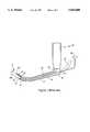
- FIG. 1illustrates one typical prior art laryngoscope, generally indicated by reference numeral 10.
- Laryngoscope 10is shown in its normal operative downwardly directed position and includes a handle 12 extending upward (to be held by the operator) and an upwardly curved tubular blade 14 which are disengagably connectable with one another.
- Blade 14includes a proximate end 16 and a distal end 18.
- Distal end 18includes a tip portion 20 which forms the leading end of the blade.
- the bladealso includes a tube passage (not shown) which extends from the proximate end to the distal end of the blade.
- the tube passagehas an entrance opening 24 at the uppermost end of the blade and an exit opening 26 at the distal end of the blade.
- a light source(not shown) located in the handle provides light to a proximate end 28 of a fiber optic lighting member 30 carried by blade 14. Light received by fiber optic member 30 is transmitted to its distal end 32 to illuminate tip portion 20 of the blade and the anatomy of a patient (not shown) adjacent the tip portion when the laryngoscope is in actual use.
- a fiber optic viewing member 34 including an end 36cooperates with the lighting member to provide for remote viewing at the tip portion using an eyepiece 38.
- an endotracheal tube 40is shown inserted through entrance 24 and on through the tube passage provided by the blade such that a leading end 40a of the tube extends outwardly from exit opening 26.
- the upward curvature of the blade near distal end 18is specifically provided to best cooperate with the pharyngeal passage of a typical patient. This curvature, as illustrated, is generally approximately circular and is carried through tip portion 20 of the blade.
- FIGS. 1While the prior art laryngoscope, as depicted in FIGS. 1, is generally satisfactory for its intended purpose, there is a particular aspect of the instrument, as shown and described above, which may be improved upon in accordance with the present invention, as will be discussed below.
- endotracheal tube 40is flexible in order to pass through the curved laryngoscope blade and in its relaxed state the tube maintains a radius of curvature which is greater than that of the distal end curve of the blade. Therefore, leading end 40a of the tube tends to follow a path upon emerging from tube passage 26 at the distal end of the blade which follows its own larger radius of curvature rather than the smaller curvature of the distal end. As a result, as leading end 40a emerges from distal end 18, it separates from tip portion 20 rather than hugging up against it, thereby defining an acute angle A therebetween.
- a first problem resulting from the divergence or spacing between the tube and the tip portionoccurs with regard to lighting member 30 and viewing member 34.
- Distal end 32 of the lighting memberis fixedly attached to the blade and aimed to illuminate an area along tip portion 20.
- end 36 of the viewing memberis also fixedly aimed along the tip portion.
- leading end 40a of the tubewill move out of the field of view of the viewing member or out of the area which is illuminated by the lighting member as the tube diverges from the tip portion in a downward direction. The benefit of the viewing member is thus lost at the critical point of the intubation procedure when it is desired to place the tube into the trachea.
- the health care practitionermay have to manipulate the end of the blade in certain ways in order to properly align the tube with the patient's trachea.
- the present inventionprovides a solution for the problems caused by the emerging leading end of the tube diverging from the tip portion of the blade.
- This laryngoscopelike the prior art laryngoscope shown in FIG. 1, includes a handle and a blade disengagably connectable with the handle.
- the bladehaving a tube guiding portion with a proximate end adjacent the handle and a distal end further from the handle when the blade is connected therewith. At least a segment of the tube guiding portion including the distal end defines an upwardly curved path, when the blade and handle are disposed in their normal, operative downwardly directed position as is shown in FIG. 2.
- the tube guiding portionis configured to receive and route the flexible tube from its proximate end to the distal end along the curved path such that, upon emerging from the tube guiding portion at the distal end, the tube at least initially follows the same path described above with respect to FIG. 1.
- the present bladewhile still maintaining its upward curve which enables it to lift the epiglottis, includes a tip portion which extends forward from the distal end of the tube guiding portion in a direction immediately adjacent the tube as the latter emerges from the tube guiding portion, thereby eliminating the separation associated with the prior art arrangement described above.
- the handleis disengagably connectable with the blade and the latter includes a tube guiding portion having a proximate end adjacent the handle and a curved segment including a distal end which is further from the handle, such that the curved segment defines a curved path
- the methodincludes steps of: inserting the blade into the patient such that the blade curves upwardly, guiding the tube from the proximate end of the tube guiding portion to cause it to emerge therefrom at the distal end such that the tube at least initially follows a path away from the curved path, and providing a tip portion which extends forward from the distal end of the tube guiding portion in a direction immediately adjacent the tube as it emerges from the distal end of the blade and which also serves to elevate the patient's epiglottis while inserting the blade into the patient.
- FIG. 1illustrates a prior art laryngoscope which includes a prior art tip portion at the distal end of its blade;
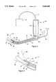
- FIG. 2is a side elevational view of a laryngoscope manufactured in accordance with the present invention including a downwardly directed tip portion;
- FIG. 3is an enlarged elevational side view of the distal end of the blade of the laryngoscope which is shown in FIG. 2.
- FIG. 2illustrates a laryngoscope manufactured in accordance with the present invention and generally designated by reference numeral 50.
- Laryngoscope 50is shown in its normal operative downwardly directed position and includes a handle 52 and an upwardly curved tubular blade 54 which is disengagably connectable with the handle, although the blade may be connected to the handle by any other suitable arrangement, such as unremovably fixing the handle to the blade.
- the laryngoscope of the present inventionmay incorporate any other feature of state of the art laryngoscopes such as, for example, a tube separation slot along a side margin of the blade. These features are not illustrated herein for simplicity.
- blade 54also includes a proximate end 56 and a distal end 58.
- a segment 59 of the blade which includes distal end 58defines a curved path, as shown, which path if extended along its radius would follow dotted line 59A in FIGS. 2 and 3.
- Segment 59includes a circular curvature in the present example, but many variations in the curvature are possible within the scope of the invention and may be found to be useful.
- a tube guiding portionwhich is not shown for simplicity, typical of prior art laryngoscopes, is formed by the tubular blade along its length and includes an entrance opening 60 at the proximate end of the blade and an exit opening 62 at the distal end of the blade.
- a flexible endotracheal tube 64is shown inserted into the tube guiding portion such that a leading end 66 of the tube extends outwardly from exit opening 62.
- leading end 66 of flexible tube 64emerges from exit opening 62 along an initial path 68, it follows its own natural curvature which has a larger radius than the radius of curvature of segment 59 of the blade.
- the flexibility and behavior of the endotracheal tube, as just described,is typical of currently available endotracheal tubes.
- a tip portion 70 integral with the distal end of the bladeextends forward at an angle relative to the curved path defined by segment 59 of the tube guiding portion of the blade which directs the tip portion downward relative to the curved path in the direction of the emerging endotracheal tube in a manner such that the tip portion is immediately adjacent (touching or almost touching) the tube as it emerges from the blade along initial path 68.
- a variety of alternative configurations, other than the preferred embodiment described herein, for providing a tip portionare possible such as, for example, fixedly attaching a separate tip portion to the blade.
- the tip portionis configured to maintain its upward curvature but is bent downward at its most proximal portion and thus some curvature both along its length and cross-section may be found to be useful.
- the use of the laryngoscope including a tip portion which is immediately adjacent with the initial emerging path of the tubewill be described hereinafter.
- a remote light source 72which is schematically illustrated, is connected to the handle by a fiber optic cable 74.
- Fiber optic cable 74extends from the light source means to the handle and includes an end portion 74a which extends through the length of the handle.
- a light guide 76extends along the length of the blade and includes a proximate end 78 which is disposed directly adjacent and opposite end portion 74a of the fiber optic cable when the blade is attached to the handle, as shown.
- Remote light source 72may be provided by a variety of light producing configurations, within the scope of the present invention. It is noted herein that an advantage is provided by the preferred embodiment described above, in that this configuration is capable of providing a light source which is typically much brighter than lighting means used with previous laryngoscopes.
- light guide 76further includes an end segment 80 having an end face 82 at the distal end of the blade.
- Light originally incident upon proximate end 78 of the light guideis emitted from end face 82 to provide light along and directly forward of tip portion 70.
- the unique feature of this light guideresides in the disposition of end segment 80 on the blade.
- End segment 80does not follow the general curvature of segment 59 of the blade but, rather, is aimed to project light from end face 80 along the tip portion in alignment with initial path 68 taken by the emerging endotracheal tube.
- the projected lightadvantageously illuminates the tube and tip portion when the laryngoscope is oriented in its normal downward position in an operative procedure.
- a flexible fiber optic viewing member 84 having a segment 85 attached to a side margin of the bladealso includes a pickup end 86 to provide for remote viewing of the tip portion at an eyepiece 88 by transmitting reflected light which is incident on end 86 to the eyepiece.
- the eyepiecemay also be adaptable for use with a video camera in which case the procedure may be observed on a video monitor.
- an end segment 90 at the distal end of viewing member 84positions pickup end 86 of the viewing member so as to provide a view at eyepiece 88 which looks along tip portion 70 in general alignment with initial path 68.
- the laryngoscope bladeIn use the laryngoscope blade is attached to the handle in its normal operative position, as shown in FIG. 2, and optical light source means 72 couples light to light guide 76 from end segment 74a of the fiber optic cable, as previously described.
- the bladeis inserted into the throat of a patient (not shown) with segment 54a curving upwardly, as shown in FIG. 2.
- Tip portion 70is used, as in prior art laryngoscopes, to elevate the epiglottis of the patient as the blade is inserted. In actual practice and as an unexpected benefit of the present invention, tip portion 70 has exhibited a general ease of use in being positioned under and elevating the epiglottis.
- the laryngoscope of the present inventionmay be produced from a variety of materials, for example, such as stainless steel or suitable plastics which may even provide for disposability or a degree of flexibility in the blade. It is also anticipated herein that blades incorporating the features of the present invention may be provided which are adaptable for use with various prior art laryngoscope handles, which are currently in use, to provide the advantages herein disclosed.
Landscapes
- Health & Medical Sciences (AREA)
- Life Sciences & Earth Sciences (AREA)
- Surgery (AREA)
- Biomedical Technology (AREA)
- Medical Informatics (AREA)
- Optics & Photonics (AREA)
- Pathology (AREA)
- Radiology & Medical Imaging (AREA)
- Biophysics (AREA)
- Engineering & Computer Science (AREA)
- Physics & Mathematics (AREA)
- Heart & Thoracic Surgery (AREA)
- Nuclear Medicine, Radiotherapy & Molecular Imaging (AREA)
- Molecular Biology (AREA)
- Animal Behavior & Ethology (AREA)
- General Health & Medical Sciences (AREA)
- Public Health (AREA)
- Veterinary Medicine (AREA)
- Pulmonology (AREA)
- Otolaryngology (AREA)
- Physiology (AREA)
- Endoscopes (AREA)
Abstract
Description
Claims (16)
Priority Applications (1)
| Application Number | Priority Date | Filing Date | Title |
|---|---|---|---|
| US08/427,416US5603688A (en) | 1995-04-24 | 1995-04-24 | Laryngoscope including an upwardly curved blade having a downwardly directed tip portion |
Applications Claiming Priority (1)
| Application Number | Priority Date | Filing Date | Title |
|---|---|---|---|
| US08/427,416US5603688A (en) | 1995-04-24 | 1995-04-24 | Laryngoscope including an upwardly curved blade having a downwardly directed tip portion |
Publications (1)
| Publication Number | Publication Date |
|---|---|
| US5603688Atrue US5603688A (en) | 1997-02-18 |
Family
ID=23694783
Family Applications (1)
| Application Number | Title | Priority Date | Filing Date |
|---|---|---|---|
| US08/427,416Expired - Fee RelatedUS5603688A (en) | 1995-04-24 | 1995-04-24 | Laryngoscope including an upwardly curved blade having a downwardly directed tip portion |
Country Status (1)
| Country | Link |
|---|---|
| US (1) | US5603688A (en) |
Cited By (43)
| Publication number | Priority date | Publication date | Assignee | Title |
|---|---|---|---|---|
| US5888195A (en)* | 1998-03-26 | 1999-03-30 | Schneider; Cary N. | Laryngoscope blade |
| WO1999027840A1 (en)* | 1997-12-01 | 1999-06-10 | Pacey John A | Intubation instrument |
| WO1999029228A1 (en)* | 1997-12-10 | 1999-06-17 | Young, Navaneswary | Multi-angle viewing fibreoptic laryngoscope |
| WO1999044490A1 (en)* | 1998-03-01 | 1999-09-10 | Volpi Ag | Laryngoscope |
| US5993383A (en)* | 1999-05-27 | 1999-11-30 | Haase; Brian J. | Laryngoscope blade with tongue controlling wing sections |
| US6007487A (en)* | 1996-03-22 | 1999-12-28 | Sdgi Holdings, Inc. | Tissue retractor for use through a cannula |
| US6123666A (en)* | 1998-04-29 | 2000-09-26 | Vanderbilt University | Laryngoscope blade with fiberoptic scope for remote viewing and method for teaching the proper insertion of a laryngoscope blade into the airway of a patient |
| US6206826B1 (en) | 1997-12-18 | 2001-03-27 | Sdgi Holdings, Inc. | Devices and methods for percutaneous surgery |
| US6217509B1 (en) | 1996-03-22 | 2001-04-17 | Sdgi Holdings, Inc. | Devices and methods for percutaneous surgery |
| US20020165444A1 (en)* | 2001-04-20 | 2002-11-07 | Whitman Michael P. | Imaging device |
| US6543447B2 (en) | 1997-12-01 | 2003-04-08 | Saturn Biomedical Systems Inc | Intubation instrument |
| US20030073998A1 (en)* | 2000-08-01 | 2003-04-17 | Endius Incorporated | Method of securing vertebrae |
| US6623425B2 (en) | 2001-07-23 | 2003-09-23 | Cartledge Medical Products, Llc | Modified laryngoscope blade to reduce dental injuries during intubation |
| US6655377B2 (en) | 1997-12-01 | 2003-12-02 | Saturn Biomedical Systems Inc. | Intubation instrument |
| US20040111012A1 (en)* | 2002-09-30 | 2004-06-10 | Whitman Michael P. | Self-contained sterilizable surgical system |
| US20040143169A1 (en)* | 2002-08-02 | 2004-07-22 | Branch Charles L. | Systems and techniques for illuminating a surgical space |
| US20040176763A1 (en)* | 1996-03-22 | 2004-09-09 | Foley Kevin T. | Methods for percutaneous surgery |
| US6840903B2 (en) | 2002-03-21 | 2005-01-11 | Nuvista Technology Corporation | Laryngoscope with image sensor |
| US20060183978A1 (en)* | 2005-02-14 | 2006-08-17 | Howard Gregory L | Laryngoscope |
| US20060241350A1 (en)* | 2005-04-22 | 2006-10-26 | Sdgi Holdings, Inc. | Instruments and methods for selective tissue retraction through a retractor sleeve |
| US20060247496A1 (en)* | 2001-10-31 | 2006-11-02 | Peter Tjong Joe Wai | Instrument for creating space in a human pharynx, and method for using the instrument |
| US20070179342A1 (en)* | 2006-01-12 | 2007-08-02 | Kb Port Llc | Wireless Laryngoscope with Internal Antennae and One Piece Construction Adapted for Laryngoscopy Training |
| US20080177147A1 (en)* | 2007-01-24 | 2008-07-24 | Jonathan Simons | Laryngoscope |
| US20080287937A1 (en)* | 2007-05-15 | 2008-11-20 | Warsaw Orthopedic, Inc. | Surgical Instrument for Illuminating and Monitoring a Surgical Site |
| US20090143645A1 (en)* | 2007-10-12 | 2009-06-04 | Beth Israel Deaconess Medical Center | Catheter guided endotracheal intubation |
| US7751870B2 (en) | 2002-01-30 | 2010-07-06 | Power Medical Interventions, Llc | Surgical imaging device |
| US20100199999A1 (en)* | 2009-02-06 | 2010-08-12 | Vazales Brad E | Methods for cleaning endotracheal tubes |
| US20110023887A1 (en)* | 2009-02-06 | 2011-02-03 | Endoclear, Llc | Methods for tracheostomy visualization |
| US20110120474A1 (en)* | 2007-04-16 | 2011-05-26 | David Alan Daugherty | Airway devices, tube securing devices, and methods of making and using the same |
| US20110130632A1 (en)* | 2009-11-30 | 2011-06-02 | King Systems Corporation | Visualization Instrument |
| US7985247B2 (en) | 2000-08-01 | 2011-07-26 | Zimmer Spine, Inc. | Methods and apparatuses for treating the spine through an access device |
| US20120029293A1 (en)* | 2010-07-30 | 2012-02-02 | Vasan Nilesh R | Disposable, Self-Contained Laryngoscope and Method of Using Same |
| US8229549B2 (en) | 2004-07-09 | 2012-07-24 | Tyco Healthcare Group Lp | Surgical imaging device |
| US8540746B2 (en) | 1998-08-20 | 2013-09-24 | Zimmer Spine, Inc. | Cannula for receiving surgical instruments |
| US20140316206A1 (en)* | 2010-07-30 | 2014-10-23 | Nilesh R. Vasan | Disposable, self-contained laryngoscope and method of using same |
| US9445714B2 (en) | 2010-03-29 | 2016-09-20 | Endoclear Llc | Endotracheal tube coupling adapters |
| US9622651B2 (en) | 2012-01-27 | 2017-04-18 | Kbport Llc | Wireless laryngoscope simulator with onboard event recording adapted for laryngoscopy training |
| US20170258313A1 (en)* | 2005-12-09 | 2017-09-14 | Aircraft Medical Limited | Laryngoscope blade |
| US9820642B2 (en) | 2007-08-04 | 2017-11-21 | King Systems Corporation | Airway intubation device |
| US10004863B2 (en) | 2012-12-04 | 2018-06-26 | Endoclear Llc | Closed suction cleaning devices, systems and methods |
| US10016575B2 (en) | 2014-06-03 | 2018-07-10 | Endoclear Llc | Cleaning devices, systems and methods |
| USD876625S1 (en) | 2018-08-07 | 2020-02-25 | Adroit Surgical, Llc | Laryngoscope |
| US10722322B2 (en) | 2010-03-29 | 2020-07-28 | Endoclear Llc | Distal airway cleaning devices |
Citations (7)
| Publication number | Priority date | Publication date | Assignee | Title |
|---|---|---|---|---|
| US3848587A (en)* | 1972-11-21 | 1974-11-19 | B Mcdonald | Ear, nose and throat examining instrument |
| US4360008A (en)* | 1980-09-02 | 1982-11-23 | Corazzelli Jr Frank G | Laryngoscope |
| US4384570A (en)* | 1979-01-02 | 1983-05-24 | Roberts James T | Laryngoscope |
| US4527553A (en)* | 1980-04-28 | 1985-07-09 | Upsher Michael S | Laryngoscope with improved light source |
| US4567882A (en)* | 1982-12-06 | 1986-02-04 | Vanderbilt University | Method for locating the illuminated tip of an endotracheal tube |
| US4573451A (en)* | 1984-11-08 | 1986-03-04 | Jack Bauman | Laryngoscope blade with a bendable tip |
| US4705024A (en)* | 1986-06-20 | 1987-11-10 | Bainton Cedric R | Laryngoscope for use with pharyngeal obstructions |
- 1995
- 1995-04-24USUS08/427,416patent/US5603688A/ennot_activeExpired - Fee Related
Patent Citations (7)
| Publication number | Priority date | Publication date | Assignee | Title |
|---|---|---|---|---|
| US3848587A (en)* | 1972-11-21 | 1974-11-19 | B Mcdonald | Ear, nose and throat examining instrument |
| US4384570A (en)* | 1979-01-02 | 1983-05-24 | Roberts James T | Laryngoscope |
| US4527553A (en)* | 1980-04-28 | 1985-07-09 | Upsher Michael S | Laryngoscope with improved light source |
| US4360008A (en)* | 1980-09-02 | 1982-11-23 | Corazzelli Jr Frank G | Laryngoscope |
| US4567882A (en)* | 1982-12-06 | 1986-02-04 | Vanderbilt University | Method for locating the illuminated tip of an endotracheal tube |
| US4573451A (en)* | 1984-11-08 | 1986-03-04 | Jack Bauman | Laryngoscope blade with a bendable tip |
| US4705024A (en)* | 1986-06-20 | 1987-11-10 | Bainton Cedric R | Laryngoscope for use with pharyngeal obstructions |
Cited By (105)
| Publication number | Priority date | Publication date | Assignee | Title |
|---|---|---|---|---|
| US6007487A (en)* | 1996-03-22 | 1999-12-28 | Sdgi Holdings, Inc. | Tissue retractor for use through a cannula |
| US20040176763A1 (en)* | 1996-03-22 | 2004-09-09 | Foley Kevin T. | Methods for percutaneous surgery |
| US6520907B1 (en) | 1996-03-22 | 2003-02-18 | Sdgi Holdings, Inc. | Methods for accessing the spinal column |
| US20070156020A1 (en)* | 1996-03-22 | 2007-07-05 | Foley Kevin T | Methods for percutaneous spinal surgery |
| US6217509B1 (en) | 1996-03-22 | 2001-04-17 | Sdgi Holdings, Inc. | Devices and methods for percutaneous surgery |
| US20030139648A1 (en)* | 1996-03-22 | 2003-07-24 | Foley Kevin Thomas | Devices and methods for percutaneous surgery |
| US7993378B2 (en) | 1996-03-22 | 2011-08-09 | Warsaw Orthopedic, IN. | Methods for percutaneous spinal surgery |
| US6425859B1 (en) | 1996-03-22 | 2002-07-30 | Sdgi Holdings, Inc. | Cannula and a retractor for percutaneous surgery |
| US6206822B1 (en) | 1996-03-22 | 2001-03-27 | Sdgi Holdings, Inc. | Devices and methods for percutaneous surgery |
| WO1999027840A1 (en)* | 1997-12-01 | 1999-06-10 | Pacey John A | Intubation instrument |
| US6142144A (en)* | 1997-12-01 | 2000-11-07 | Pacey; John A. | Intubation instrument |
| US6655377B2 (en) | 1997-12-01 | 2003-12-02 | Saturn Biomedical Systems Inc. | Intubation instrument |
| US6543447B2 (en) | 1997-12-01 | 2003-04-08 | Saturn Biomedical Systems Inc | Intubation instrument |
| WO1999029228A1 (en)* | 1997-12-10 | 1999-06-17 | Young, Navaneswary | Multi-angle viewing fibreoptic laryngoscope |
| US6206826B1 (en) | 1997-12-18 | 2001-03-27 | Sdgi Holdings, Inc. | Devices and methods for percutaneous surgery |
| WO1999044490A1 (en)* | 1998-03-01 | 1999-09-10 | Volpi Ag | Laryngoscope |
| USRE37861E1 (en)* | 1998-03-26 | 2002-09-24 | Cary N. Schneider | Laryngoscope blade |
| US5888195A (en)* | 1998-03-26 | 1999-03-30 | Schneider; Cary N. | Laryngoscope blade |
| WO1999048416A1 (en)* | 1998-03-26 | 1999-09-30 | Schneider Cary N | Improved laryngoscope blade |
| US6123666A (en)* | 1998-04-29 | 2000-09-26 | Vanderbilt University | Laryngoscope blade with fiberoptic scope for remote viewing and method for teaching the proper insertion of a laryngoscope blade into the airway of a patient |
| US8540746B2 (en) | 1998-08-20 | 2013-09-24 | Zimmer Spine, Inc. | Cannula for receiving surgical instruments |
| US5993383A (en)* | 1999-05-27 | 1999-11-30 | Haase; Brian J. | Laryngoscope blade with tongue controlling wing sections |
| US7722530B2 (en) | 2000-08-01 | 2010-05-25 | Zimmer Spine, Inc. | Method of securing vertebrae |
| US8777997B2 (en) | 2000-08-01 | 2014-07-15 | Zimmer Spine, Inc. | Method for securing vertebrae |
| US7985247B2 (en) | 2000-08-01 | 2011-07-26 | Zimmer Spine, Inc. | Methods and apparatuses for treating the spine through an access device |
| US20040082960A1 (en)* | 2000-08-01 | 2004-04-29 | Davison Thomas W. | Method of securing vertebrae |
| US20040236317A1 (en)* | 2000-08-01 | 2004-11-25 | Davison Thomas W. | Method of securing vertebrae |
| US9101353B2 (en) | 2000-08-01 | 2015-08-11 | Zimmer Spine, Inc. | Method of securing vertebrae |
| US20050021030A1 (en)* | 2000-08-01 | 2005-01-27 | Endius Incorporated | Method of securing vertebrae |
| US20030073998A1 (en)* | 2000-08-01 | 2003-04-17 | Endius Incorporated | Method of securing vertebrae |
| US20050113833A1 (en)* | 2000-08-01 | 2005-05-26 | Davison Thomas W. | Method of securing vertebrae |
| US9622735B2 (en) | 2000-08-01 | 2017-04-18 | Zimmer Spine, Inc. | Method for securing vertebrae |
| US7056321B2 (en) | 2000-08-01 | 2006-06-06 | Endius, Incorporated | Method of securing vertebrae |
| US7850695B2 (en) | 2000-08-01 | 2010-12-14 | Zimmer Spine, Inc. | Method of securing vertebrae |
| US8864785B2 (en) | 2000-08-01 | 2014-10-21 | Zimmer Spine, Inc. | Method for securing vertebrae |
| US7699877B2 (en) | 2000-08-01 | 2010-04-20 | Zimmer Spine, Inc. | Method of securing vertebrae |
| US8277486B2 (en) | 2000-08-01 | 2012-10-02 | Zimmer Spine, Inc. | System for performing a procedure at a spinal location |
| US8262560B2 (en) | 2001-04-20 | 2012-09-11 | Tyco Healthcare Group Lp | Imaging device for use with a surgical device |
| US20020165444A1 (en)* | 2001-04-20 | 2002-11-07 | Whitman Michael P. | Imaging device |
| US7044910B2 (en) | 2001-07-23 | 2006-05-16 | Cartledge Medical Products, Inc. | Modified laryngoscope blade to reduce dental injuries during intubation |
| US20040034281A1 (en)* | 2001-07-23 | 2004-02-19 | Richard Cartledge | Modified laryngoscope blade to reduce dental injuries during intubation |
| US6623425B2 (en) | 2001-07-23 | 2003-09-23 | Cartledge Medical Products, Llc | Modified laryngoscope blade to reduce dental injuries during intubation |
| US20060247496A1 (en)* | 2001-10-31 | 2006-11-02 | Peter Tjong Joe Wai | Instrument for creating space in a human pharynx, and method for using the instrument |
| US9867523B2 (en) | 2002-01-30 | 2018-01-16 | Covidien Lp | Surgical imaging device |
| US7751870B2 (en) | 2002-01-30 | 2010-07-06 | Power Medical Interventions, Llc | Surgical imaging device |
| US8812086B2 (en) | 2002-01-30 | 2014-08-19 | Covidien Lp | Surgical imaging device |
| US20050043590A1 (en)* | 2002-03-21 | 2005-02-24 | Mazzei William J. | Laryngoscope with image sensor |
| US6840903B2 (en) | 2002-03-21 | 2005-01-11 | Nuvista Technology Corporation | Laryngoscope with image sensor |
| US7556601B2 (en)* | 2002-08-02 | 2009-07-07 | Warsaw Orthopedic, Inc. | Systems and techniques for illuminating a surgical space |
| US20040143169A1 (en)* | 2002-08-02 | 2004-07-22 | Branch Charles L. | Systems and techniques for illuminating a surgical space |
| US8696552B2 (en) | 2002-09-30 | 2014-04-15 | Covidien Lp | Self-contained sterilizable surgical system |
| US20040111012A1 (en)* | 2002-09-30 | 2004-06-10 | Whitman Michael P. | Self-contained sterilizable surgical system |
| US8229549B2 (en) | 2004-07-09 | 2012-07-24 | Tyco Healthcare Group Lp | Surgical imaging device |
| US8862209B2 (en) | 2004-07-09 | 2014-10-14 | Covidien Lp | Surgical imaging device |
| US20060183978A1 (en)* | 2005-02-14 | 2006-08-17 | Howard Gregory L | Laryngoscope |
| US7427264B2 (en) | 2005-04-22 | 2008-09-23 | Warsaw Orthopedic, Inc. | Instruments and methods for selective tissue retraction through a retractor sleeve |
| US20060241350A1 (en)* | 2005-04-22 | 2006-10-26 | Sdgi Holdings, Inc. | Instruments and methods for selective tissue retraction through a retractor sleeve |
| US20170258313A1 (en)* | 2005-12-09 | 2017-09-14 | Aircraft Medical Limited | Laryngoscope blade |
| US11517193B2 (en)* | 2005-12-09 | 2022-12-06 | Covidien Ag | Laryngoscope blade |
| US20070179342A1 (en)* | 2006-01-12 | 2007-08-02 | Kb Port Llc | Wireless Laryngoscope with Internal Antennae and One Piece Construction Adapted for Laryngoscopy Training |
| US20100191061A1 (en)* | 2007-01-24 | 2010-07-29 | Zeppelin Designs Inc. | Laryngoscope with disposable blade cover |
| US7695433B2 (en) | 2007-01-24 | 2010-04-13 | Zeppelin Designs, Inc. | Laryngoscope with disposable blade cover |
| US20080177147A1 (en)* | 2007-01-24 | 2008-07-24 | Jonathan Simons | Laryngoscope |
| US20110120474A1 (en)* | 2007-04-16 | 2011-05-26 | David Alan Daugherty | Airway devices, tube securing devices, and methods of making and using the same |
| US8800566B2 (en) | 2007-04-16 | 2014-08-12 | Ecolab Usa Inc. | Airway devices, tube securing devices, and methods of making and using the same |
| US20080287937A1 (en)* | 2007-05-15 | 2008-11-20 | Warsaw Orthopedic, Inc. | Surgical Instrument for Illuminating and Monitoring a Surgical Site |
| US9820642B2 (en) | 2007-08-04 | 2017-11-21 | King Systems Corporation | Airway intubation device |
| US20090143645A1 (en)* | 2007-10-12 | 2009-06-04 | Beth Israel Deaconess Medical Center | Catheter guided endotracheal intubation |
| US10182712B2 (en)* | 2007-10-12 | 2019-01-22 | Beth Israel Deaconess Medical Center, Inc. | Catheter guided endotracheal intubation |
| US9332891B2 (en) | 2009-02-06 | 2016-05-10 | Endoclear Llc | Tracheostomy visualization |
| US20110023887A1 (en)* | 2009-02-06 | 2011-02-03 | Endoclear, Llc | Methods for tracheostomy visualization |
| US8157919B2 (en) | 2009-02-06 | 2012-04-17 | Endoclear, Llc | Methods for removing debris from medical tubes |
| US10682203B2 (en) | 2009-02-06 | 2020-06-16 | Endoclear Llc | Methods of cleaning endotracheal tubes including light treatment |
| US9962233B2 (en) | 2009-02-06 | 2018-05-08 | Endoclear Llc | Body-inserted tube cleaning |
| US9095286B2 (en) | 2009-02-06 | 2015-08-04 | Endoclear Llc | Body-inserted tube cleaning |
| US9907624B2 (en) | 2009-02-06 | 2018-03-06 | Endoclear Llc | Body-inserted tube cleaning with suction |
| US8468637B2 (en) | 2009-02-06 | 2013-06-25 | Endoclear Llc | Mechanically-actuated endotracheal tube cleaning device |
| US10441380B2 (en) | 2009-02-06 | 2019-10-15 | Endoclear Llc | Body-inserted tube cleaning |
| US8382908B2 (en) | 2009-02-06 | 2013-02-26 | Endoclear, Llc | Methods for cleaning endotracheal tubes |
| US9386907B2 (en) | 2009-02-06 | 2016-07-12 | Endoclear Llc | Visualization systems and methods |
| US8458844B2 (en) | 2009-02-06 | 2013-06-11 | Endoclear, Llc | Medical tube cleaning apparatus |
| US9398837B2 (en) | 2009-02-06 | 2016-07-26 | Endoclear Llc | Methods for confirming placement of endotracheal tubes |
| US9855111B2 (en) | 2009-02-06 | 2018-01-02 | Endoclear Llc | Methods of removing biofilm from endotracheal tubes |
| US9579012B2 (en) | 2009-02-06 | 2017-02-28 | Endoclear Llc | Visualized endotracheal tube placement systems |
| US8534287B2 (en) | 2009-02-06 | 2013-09-17 | Endoclear, Llc | Methods for tracheostomy visualization |
| US8381345B2 (en) | 2009-02-06 | 2013-02-26 | Endoclear, Llc | Devices for cleaning endotracheal tubes |
| US20100199999A1 (en)* | 2009-02-06 | 2010-08-12 | Vazales Brad E | Methods for cleaning endotracheal tubes |
| US8601633B2 (en) | 2009-02-06 | 2013-12-10 | Endoclear Llc | Cleaning of body-inserted medical tubes |
| US9854962B2 (en) | 2009-11-30 | 2018-01-02 | King Systems Corporation | Visualization instrument |
| US9179831B2 (en) | 2009-11-30 | 2015-11-10 | King Systems Corporation | Visualization instrument |
| US20110130632A1 (en)* | 2009-11-30 | 2011-06-02 | King Systems Corporation | Visualization Instrument |
| US9445714B2 (en) | 2010-03-29 | 2016-09-20 | Endoclear Llc | Endotracheal tube coupling adapters |
| US10722322B2 (en) | 2010-03-29 | 2020-07-28 | Endoclear Llc | Distal airway cleaning devices |
| US20120029293A1 (en)* | 2010-07-30 | 2012-02-02 | Vasan Nilesh R | Disposable, Self-Contained Laryngoscope and Method of Using Same |
| US11478139B2 (en) | 2010-07-30 | 2022-10-25 | Adroit Surgical, Llc | Disposable, self-contained laryngoscope and method of using same |
| US9386915B2 (en)* | 2010-07-30 | 2016-07-12 | Nilesh R. Vasan | Disposable, self-contained laryngoscope and method of using same |
| US9289114B2 (en)* | 2010-07-30 | 2016-03-22 | Nilesh R. Vasan | Disposable, self-contained laryngoscope and method of using same |
| US20140316206A1 (en)* | 2010-07-30 | 2014-10-23 | Nilesh R. Vasan | Disposable, self-contained laryngoscope and method of using same |
| US9622651B2 (en) | 2012-01-27 | 2017-04-18 | Kbport Llc | Wireless laryngoscope simulator with onboard event recording adapted for laryngoscopy training |
| US10821249B2 (en) | 2012-12-04 | 2020-11-03 | Endoclear Llc | Closed suction cleaning devices, systems and methods |
| US11173266B2 (en) | 2012-12-04 | 2021-11-16 | Endoclear Llc | Closed suction cleaning devices, systems and methods |
| US10004863B2 (en) | 2012-12-04 | 2018-06-26 | Endoclear Llc | Closed suction cleaning devices, systems and methods |
| US10850062B2 (en) | 2014-06-03 | 2020-12-01 | Endoclear Llc | Cleaning devices, systems and methods |
| US10016575B2 (en) | 2014-06-03 | 2018-07-10 | Endoclear Llc | Cleaning devices, systems and methods |
| USD876625S1 (en) | 2018-08-07 | 2020-02-25 | Adroit Surgical, Llc | Laryngoscope |
Similar Documents
| Publication | Publication Date | Title |
|---|---|---|
| US5603688A (en) | Laryngoscope including an upwardly curved blade having a downwardly directed tip portion | |
| EP1307131B2 (en) | Intubation instrument | |
| US5676635A (en) | Instrument for insertion of an endotracheal tube | |
| US10368732B2 (en) | Airway intubation device | |
| US5845634A (en) | Endoscope viewing system with orotracheal introducing guide | |
| US5607386A (en) | Malleable fiberoptic intubating stylet and method | |
| US5183031A (en) | Fiberoptic intubating laryngoscope | |
| US6655377B2 (en) | Intubation instrument | |
| JP5650744B2 (en) | Laryngoscope | |
| US20070049794A1 (en) | Visualization stylet for medical device applications having self-contained power source | |
| US20040215061A1 (en) | Visualization stylet for endotracheal intubation | |
| WO1995018643A1 (en) | Easy intubator | |
| US5279281A (en) | Single-handed fibre-optic flexible laryngoscope | |
| US8388524B2 (en) | Medical instruments having video capabiility | |
| CN211093963U (en) | Bendable video laryngoscope | |
| CN209347858U (en) | A kind of trachea intubation device | |
| CN109224232A (en) | A kind of trachea intubation device | |
| US20070129607A1 (en) | Laryngoscope blade | |
| CN216985973U (en) | Intubation device capable of being used for difficult airway independently or in cooperation with fiber bronchoscope | |
| HK1057323B (en) | Intubation instrument | |
| JP2003116778A (en) | Intubation endoscope | |
| HK1037122B (en) | Endoscope viewing system with orotracheal introducing guide | |
| ITMI950332A1 (en) | Laryngoscope. |
Legal Events
| Date | Code | Title | Description |
|---|---|---|---|
| AS | Assignment | Owner name:UPSHER LARYNGOSCOPE CORPORATION, CALIFORNIA Free format text:ASSIGNMENT OF ASSIGNORS INTEREST;ASSIGNOR:UPSHER, MICHAEL S.;REEL/FRAME:007502/0678 Effective date:19950413 | |
| AS | Assignment | Owner name:MERCURY ENTERPRISES, INC., FLORIDA Free format text:ASSIGNMENT OF ASSIGNORS INTEREST;ASSIGNOR:UPSHER LARYNGOSCOPE CORPORATION, THE;REEL/FRAME:008639/0261 Effective date:19970529 | |
| FEPP | Fee payment procedure | Free format text:PAYER NUMBER DE-ASSIGNED (ORIGINAL EVENT CODE: RMPN); ENTITY STATUS OF PATENT OWNER: SMALL ENTITY Free format text:PAYOR NUMBER ASSIGNED (ORIGINAL EVENT CODE: ASPN); ENTITY STATUS OF PATENT OWNER: SMALL ENTITY | |
| FPAY | Fee payment | Year of fee payment:4 | |
| FPAY | Fee payment | Year of fee payment:8 | |
| REMI | Maintenance fee reminder mailed | ||
| LAPS | Lapse for failure to pay maintenance fees | ||
| LAPS | Lapse for failure to pay maintenance fees | Free format text:PATENT EXPIRED FOR FAILURE TO PAY MAINTENANCE FEES (ORIGINAL EVENT CODE: EXP.); ENTITY STATUS OF PATENT OWNER: SMALL ENTITY | |
| STCH | Information on status: patent discontinuation | Free format text:PATENT EXPIRED DUE TO NONPAYMENT OF MAINTENANCE FEES UNDER 37 CFR 1.362 | |
| FP | Lapsed due to failure to pay maintenance fee | Effective date:20090218 |