US5603638A - Housing for female receptacles in a molded plug - Google Patents
Housing for female receptacles in a molded plugDownload PDFInfo
- Publication number
- US5603638A US5603638AUS08/504,683US50468395AUS5603638AUS 5603638 AUS5603638 AUS 5603638AUS 50468395 AUS50468395 AUS 50468395AUS 5603638 AUS5603638 AUS 5603638A
- Authority
- US
- United States
- Prior art keywords
- cover
- housing
- cavity
- female
- electric contact
- Prior art date
- Legal status (The legal status is an assumption and is not a legal conclusion. Google has not performed a legal analysis and makes no representation as to the accuracy of the status listed.)
- Expired - Fee Related
Links
- 238000000465mouldingMethods0.000claimsabstractdescription31
- 230000013011matingEffects0.000claimsdescription11
- 230000002452interceptive effectEffects0.000claimsdescription4
- 210000003739neckAnatomy0.000abstractdescription12
- 238000002788crimpingMethods0.000description8
- 238000000034methodMethods0.000description6
- 230000008569processEffects0.000description6
- 150000001875compoundsChemical class0.000description5
- 230000008901benefitEffects0.000description4
- 239000004020conductorSubstances0.000description3
- 230000003993interactionEffects0.000description3
- 238000003780insertionMethods0.000description2
- 230000037431insertionEffects0.000description2
- 230000006835compressionEffects0.000description1
- 238000007906compressionMethods0.000description1
- 230000009969flowable effectEffects0.000description1
- 230000014509gene expressionEffects0.000description1
- 238000001746injection mouldingMethods0.000description1
- 230000014759maintenance of locationEffects0.000description1
- 230000007246mechanismEffects0.000description1
- 238000012986modificationMethods0.000description1
- 230000004048modificationEffects0.000description1
- 239000012778molding materialSubstances0.000description1
- 238000007789sealingMethods0.000description1
- 238000000926separation methodMethods0.000description1
Images


Classifications
- H—ELECTRICITY
- H01—ELECTRIC ELEMENTS
- H01R—ELECTRICALLY-CONDUCTIVE CONNECTIONS; STRUCTURAL ASSOCIATIONS OF A PLURALITY OF MUTUALLY-INSULATED ELECTRICAL CONNECTING ELEMENTS; COUPLING DEVICES; CURRENT COLLECTORS
- H01R24/00—Two-part coupling devices, or either of their cooperating parts, characterised by their overall structure
- H01R24/20—Coupling parts carrying sockets, clips or analogous contacts and secured only to wire or cable
- H01R24/22—Coupling parts carrying sockets, clips or analogous contacts and secured only to wire or cable with additional earth or shield contacts
- H—ELECTRICITY
- H01—ELECTRIC ELEMENTS
- H01R—ELECTRICALLY-CONDUCTIVE CONNECTIONS; STRUCTURAL ASSOCIATIONS OF A PLURALITY OF MUTUALLY-INSULATED ELECTRICAL CONNECTING ELEMENTS; COUPLING DEVICES; CURRENT COLLECTORS
- H01R43/00—Apparatus or processes specially adapted for manufacturing, assembling, maintaining, or repairing of line connectors or current collectors or for joining electric conductors
- H01R43/20—Apparatus or processes specially adapted for manufacturing, assembling, maintaining, or repairing of line connectors or current collectors or for joining electric conductors for assembling or disassembling contact members with insulating base, case or sleeve
- H01R43/24—Assembling by moulding on contact members
- H—ELECTRICITY
- H01—ELECTRIC ELEMENTS
- H01R—ELECTRICALLY-CONDUCTIVE CONNECTIONS; STRUCTURAL ASSOCIATIONS OF A PLURALITY OF MUTUALLY-INSULATED ELECTRICAL CONNECTING ELEMENTS; COUPLING DEVICES; CURRENT COLLECTORS
- H01R13/00—Details of coupling devices of the kinds covered by groups H01R12/70 or H01R24/00 - H01R33/00
- H01R13/46—Bases; Cases
- H01R13/502—Bases; Cases composed of different pieces
- H01R13/506—Bases; Cases composed of different pieces assembled by snap action of the parts
- H—ELECTRICITY
- H01—ELECTRIC ELEMENTS
- H01R—ELECTRICALLY-CONDUCTIVE CONNECTIONS; STRUCTURAL ASSOCIATIONS OF A PLURALITY OF MUTUALLY-INSULATED ELECTRICAL CONNECTING ELEMENTS; COUPLING DEVICES; CURRENT COLLECTORS
- H01R2103/00—Two poles
- H—ELECTRICITY
- H01—ELECTRIC ELEMENTS
- H01R—ELECTRICALLY-CONDUCTIVE CONNECTIONS; STRUCTURAL ASSOCIATIONS OF A PLURALITY OF MUTUALLY-INSULATED ELECTRICAL CONNECTING ELEMENTS; COUPLING DEVICES; CURRENT COLLECTORS
- H01R4/00—Electrically-conductive connections between two or more conductive members in direct contact, i.e. touching one another; Means for effecting or maintaining such contact; Electrically-conductive connections having two or more spaced connecting locations for conductors and using contact members penetrating insulation
- H01R4/10—Electrically-conductive connections between two or more conductive members in direct contact, i.e. touching one another; Means for effecting or maintaining such contact; Electrically-conductive connections having two or more spaced connecting locations for conductors and using contact members penetrating insulation effected solely by twisting, wrapping, bending, crimping, or other permanent deformation
- H01R4/18—Electrically-conductive connections between two or more conductive members in direct contact, i.e. touching one another; Means for effecting or maintaining such contact; Electrically-conductive connections having two or more spaced connecting locations for conductors and using contact members penetrating insulation effected solely by twisting, wrapping, bending, crimping, or other permanent deformation by crimping
- H01R4/183—Electrically-conductive connections between two or more conductive members in direct contact, i.e. touching one another; Means for effecting or maintaining such contact; Electrically-conductive connections having two or more spaced connecting locations for conductors and using contact members penetrating insulation effected solely by twisting, wrapping, bending, crimping, or other permanent deformation by crimping for cylindrical elongated bodies, e.g. cables having circular cross-section
- H01R4/184—Electrically-conductive connections between two or more conductive members in direct contact, i.e. touching one another; Means for effecting or maintaining such contact; Electrically-conductive connections having two or more spaced connecting locations for conductors and using contact members penetrating insulation effected solely by twisting, wrapping, bending, crimping, or other permanent deformation by crimping for cylindrical elongated bodies, e.g. cables having circular cross-section comprising a U-shaped wire-receiving portion
Definitions
- the present inventionis a housing usable as a premold for female receptacles in a molded plug.
- Some molded plugs for electronic equipmentrequire female receptacles to engage electric contact blades. In computers, particularly the electric contact blades, are oftentimes in groups of three in a triangular relationship.
- a molded plug, including the female receptacles,is usually molded with three female receptacles. Each receptacle is crimped to a wire in a cord set.
- cord setswere oftentimes machine crimped with conductors such as female receptacles in automated systems.
- the wires of the cord setwere in an automated system, to be crimped to conductors such as a female receptacle, fed from a coil or roll of conductors on the stamping strip.
- Molding of the female receptaclesis complex.
- Three crimped female receptacleshave to be positioned in the mold for injection molding, it requires substantial labor, a large volume of plastic must be used in the molding and there is always the risk of wild strands.
- a less expensive overmolding compoundcan be used due to receptacle retention characteristics. Receptacles can be automatically assembled.
- the housingallows for the crimping of three contacts in place at once instead of crimping the contacts separately.
- the housingis flash free, no overmolding compound can get between the contacts, causing discontinuity.
- the insertion and withdrawal forces associated with the introduction of the male bladesare constant, and do not vary with the overmolding compound durometer, because the contacts extension and compression are determined by its interaction with the housing.
- Prior art female business machine contact receptacleswhich are overmolded without the housing, may have problems with flashing and also insertion and withdrawal forces due to varying overmolding compound durometers.
- the present inventioninsures proper spacing of female receptacles to each other, allows for automatic assembly where all three terminals are crimped at once, reduces overmolding cycle time and labor due to ease of loading the housing into the mold and reduced plastic requirement.
- U.S. Pat. No. 3,945,708discloses a female connector including a premold for emplacing female receptacles in separate compartments.
- the premoldincludes a snap in end cover to hold the female receptacles in the premold.
- connection pairis exemplary of a male and female mating ends for a pair of power extension cords.
- the connection pairis in triangular form, or may be semicircular or rectangular.
- a premold housingcomprising a body and a cover to receive the female receptacles.
- a particular advantage of the present inventionis that the premold can receive female receptacles before they are crimped.
- the female receptaclesmay be hopper feedable into the body of the premold or loaded by severing from a stamping strip.
- the loaded body with female receptaclesis capped with a cover. Then the automated crimping of wires from a cord set to the female receptacles in the premold may be done.
- Basic advantages of the present inventionare the speed and economy of assembly of the female receptacles in the premold housing, which is automatable, the ability to crimp cord set wires to the female receptacles in the premold, the ease of handling the assembled premold, the economy of saving molding plastic in the molding process, or being able to use less expensive overmolding plastic and the improved electrical integrity of a resulting molded plug.
- the present inventioneliminates the prior art necessity of individual crimping of wires and has the advantage of being more easily managed.
- Moldingcan be prepared in a shorter time, using less molding material.
- a flash free premold housing for female receptacles molded into a plastic molded multi-opening female receptacle plughas a housing having an interengagable molded body and molded cover, to receive three female receptacles.
- the female receptacleshave a receiving portion a neck and a crimp end.
- the housinghas a body, a cover, and three cavities defined by the body and cover.
- the bodyhas three cavity portions, a front portion, a rear portion and interengagable grasping means to interactively grasp the cover.
- the coverhas a top portion and a flange portion, an inner facing portion for each cavity, a rear portion, and interengagable grasping means to interactively grasp the body.
- Each body cavity portionhas an open top part, a rear part, and an open front part.
- the flange portion of the coverextends substantially perpendicular with regard to its top portion and has three blade openings.
- the three cavitiesare in a triangular configuration, with one blade opening addressed to each cavity open front part, and one the inner facing portion of the cover forming a top with one cavity open top part.
- the body and coverhave means at each cavity rear part through the respective body and cover rear portions to accept the female receptacle extending neck portion which has a crimp end extending through the housing formed by the closely interengaged body and cover impervious to molding plastic flashing.
- the body and covercan define a cavity forming an apex of the triangular configuration and the part of the grasping means may be adjacent the apex cavity.
- the grasping meansmay be snap engagable and have a detent and an inset which may be longitudinal in the housing.
- Snap engaging meansmay have a bearing surface and a mating surface.
- the housingmay have external means between the body and cover, to non slideably interengage the snap engaged body, and cover and may include interactive edges and protrusions. There may be support means within a cavity and a through hole in the housing apart from any cavity.
- the detent and insetmay be longitudinal in the housing and have a bearing surface and a mating surface.
- a flash free premold housingfor female receptacles molded into a plastic molded multi-opening female receptacle plug with a housing having an interengagable molded body and molded cover to receive at least two the female receptacles.
- the female receptaclehave a receiving portion, a neck and a crimp end.
- the housinghas a body, a cover, at least two cavities defined by the body and the cover.
- the bodyhas at least two cavity portions, a front portion, a rear portion, and interengagable grasping means to interactively grasp the cover.
- the coverhas a top portion and a flange portion, an inner facing portion for each cavity, a rear portion, and interengagable grasping means to interactively grasp the body.
- Each body cavity portionhas an open top part, a rear part, and an open front part.
- the flange portion of the coverextends substantially perpendicular with regard to its top portion and has at least two blade openings, with one blade opening addressed to one cavity open front part and one inner facing portion of the cover, to form a top with an open top part.
- the body and coverhave means at each cavity rear part through the respective body and cover rear portions to accept the female receptacle extending neck portion, having a crimp end extending through the housing formed by the closely interengaged body and cover, impervious to molding plastic flashing.
- a part of the grasping meansmay be adjacent a cavity.
- the grasping meansmay be snap engagable and have a detent and an inset which may be longitudinal in the housing.
- the snap engagable meansmay have a bearing surface and a mating surface.
- the housingmay have external means between the body and the cover to non slideably interengage the snap engaged body and the cover. These means may include interactive edges and protrusions.
- the detent and insetmay be longitudinal in the housing and have a bearing surface and a mating surface.
- a flash free premold housing for female receptacles molded into a plastic molded multi-opening female receptacle plughaving a housing including an interengagable molded body and molded cover to receive at least three female receptacles.
- the female receptacleshave a a receiving portion a neck and a crimp end.
- the housinghas a body, a cover and three cavities defined by the body and cover, in a triangular configuration.
- the body and coverhave interengagable grasping means.
- There are blade opening means in the coverEach cavity has a front part and a rear part. The blade opening means are addressed to the cavity front part.
- the body and coverhave means at each cavity rear part through the respective body and cover rear portions to accept the female receptacle extending neck portion which has a crimp end, extending through the housing, formed by the closely interengaged body and cover impervious to molding plastic flashing.
- a flash free premold housing for female receptacles molded into a plastic molded multi-opening female receptacle plughaving a housing with an interengagable molded body and molded cover to receive three female receptacles.
- the female receptacleshave a receiving portion, a neck and a crimp end.
- the housinghas a body, a cover and three cavities defined by the body and cover.
- the bodyhas three cavity portions, a front portion, a rear portion, and interengagable grasping means to interactively grasp the cover.
- the coverhas a top portion and a flange portion, an inner facing portion for each cavity, a rear portion and interengagable grasping means to interactively grasp the body.
- Each body cavity portionhas an open top part, a rear part, and an open front part.
- the flange portion of the coverextends substantially perpendicular with regard to its top portion and has three blade openings.
- the three cavitiesare in a triangular configuration.
- One cavityforms an apex of the configuration.
- the body and cover grasping meanshave a detent and inset.
- the detent and insetare longitudinal in the housing.
- the body and cover grasping meansare adjacent the apex cavity, with one blade opening addressed to each cavity open front part and one the inner facing portion of the cover forming a top with one cavity open top part.
- the body and coverhave means at each cavity rear part through the respective body and cover rear portions, to accept the female receptacle extending neck portion, which has a crimp end extending through the housing formed by the closely interengaged body and cover impervious to molding plastic flashing.
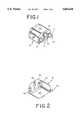
- FIG. 1is a rear isometric view of the premold housing with female receptacles engaged, the body and cover interlocked.
- FIG. 2is a front isometric view of FIG. 1 from the bottom.
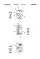
- FIG. 3is a front elevation view of FIG. 1.
- FIG. 4is a right side elevation view of FIG. 3.
- FIG. 5is a rear side elevation of view FIG. 3.
- FIG. 6top plan view of the body of the premold of FIG. 1.
- FIG. 7is an end elevation view of FIG. 6.
- FIG. 8is a left side elevation view of FIG. 6.
- FIG. 9is a right side elevation view of FIG. 6.
- FIG. 10top plan view of the cover of the premold of FIG. 1.
- FIG. 11is an end elevation view of FIG. 10.
- FIG. 12is a left side elevation view of FIG. 10.
- FIG. 13is a right side elevation view of FIG. 10.
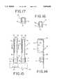
- FIG. 14is a side elevation of receptacle on a stamping strip end, which is shown in phantom.
- FIG. 15is a top plan view of FIG. 14, showing two receptacles on a stamping strip end, which is shown in phantom.
- FIG. 16is a section of one receptacle of FIG. 14 at lines 16--16.
- FIG. 17is an end elevation of one blade receptacle of FIG. 15
- FIG. 18is a bottom plan view of the premold housing of FIG. 1 molded into a plug with wires crimped, the plug shown in phantom.
- FIGS. 1-5the housing 10, acting as a premold, is shown with a body 20 and a cover 40. Within the housing 10 are female receptacles 70.
- the body 20has a first cavity 21, second cavity 22 and a third cavity 23. There are rear cutouts 24 and extending edges 25.
- the second cavity 22is elevated, has longitudinal bearing surfaces 26 and longitudinal insets 27.
- the ends of the cavities 21-23have notches 28, 29 and 30.
- the rear portion 31includes wire stops 32-34.
- Each cavity 1-23includes a pair of receptacle supports 30.
- the rear portion 31has a central opening 36 which opens to a central cavity 37 below cavity 22.
- the cover 40has a face 41 with blade openings 42.
- the cover 40has a top 43 with side bevels 44.
- the cover 40has insets 45 and end protrusions 46.
- a small opening 49 on the face 41is juxtaposable with the larger central cavity 37 of the body 20.
- the small opening 49is substantially the same size as the central opening 36 in the rear portion 31.
- the premoldas shown in FIGS. 3-5, has female receptacles 70 engaged in the cavities 21-23.
- female receptacles 70 as shown in FIGS. 14-16are engaged in the cavities 21-23.
- the female receptacle 70has a crimp end 71 and a receptacle portion 72.
- the receptacle portion 72comprises a flat side 73 and a curved side 74.
- the receptacle portion 72has a flared lip guide 76 on the curved side 74 and a flared guide lip 75 on the flat side 73.
- the crimp end 71includes crimp arms 77 and 78.
- the flat side 73 and curved side 74define an opening 79 to receive a blade.
- the blade receptacle 70is on a stamping strip end 81, shown in phantom on a stamping strip 83.
- the blade receptacles 70are stamped on the stamping strip 81, as shown in phantom, alternately folded over in parallel alignment, with the next female receptacle 70, folded over and including a folding strip 82, shown in phantom.
- FIG. 18shows a housing 10 of the present invention with female receptacles 70 engaged in a plug-in receptacle 90.
- a cord 91 with three wires 92-94has individual wires 92, 93, or 94 crimped to the crimp ends 71 on the crimp arms 77-78.
- the housing 10 of the present inventionhas female receptacles 70 engaged in the housing 10 between the cover 40 and the body 20.
- the crimp ends 71extend from the rear portion 31 of the body 20. When thus engaged, it can be seen that the blade openings 42 are in a triangular configuration in the housing 10.
- the crimp arms 77, 78 on the crimp ends 71are all facing in the same direction. The direction is selected to accommodate simultaneous automated crimping of the wires 92-94 of the cord 91.
- the openings 79 of the female receptacles 70are addressed to the blade openings 42, so when the housing 10 with the female receptacle 70 is molded into a receptacle 90, as shown in FIG. 18, a male blade (not shown), thus enters through the openings (not shown) of the receptacle 90 and is guided into the blade openings 42 of the cover 40.
- the flared lips 75, 76further guide the blades so that the male blades are engaged with full surface contact of the flat side 73.
- the female receptacle 70 disclosed in FIGS. 14-16is the subject matter of copending application Ser. No. 08/389,946, entitled Blade Receptacle.
- the female receptacle 70is the preferred embodiment of receptacle with regard to the present invention.
- the female receptacles 70 with crimp ends 71extend from the housing 10 with openings 79 addressed to the blade openings 42.
- a utility of the housing 10 of the present inventionis that receptacles 70 engaged in a housing 10 are adapted for simultaneous crimping of the wires 92 to the crimp ends 71, thus effecting additional cost saving in the molding of plugs.
- the portion between the crimp end 71 and the flat side 73 and curved side 74,is flush and engages in one of the notches 28-30.
- the engaged female receptacle 70, with its receptacle portion 72 in a cavity 21-23 and its crimp end 71, with crimp arms 77 and 78 extending,are fully engaged in the notches 28-30, so that in any molding process, there could be no flashing into the housing 10.
- the particular advantage of the premold of the present invention, when used with a female receptacle 70,is that the electrical integrity of the full surface connection on one side of a contact blade insures the electrical integrity of the receptacle 90 with its female receptacles 70.
- the female receptacles 70may be automatically insertable into bodies 20 with automation of the snap engagement of the covers 40.
- cavity 22raises the cavity 22 so that the female receptacles 70 are spaced to engage conventional business machine electrical male blade terminals (not shown).
- the raised cavity 22allows the longitudinally extending bearing surfaces 26 and insets 27 to serve as a snap fitting, to engage with the longitudinal detents 47 and the longitudinal mating surfaces 48, so that the cover 40 can be snap fit into position in locking integrity.
- the housing 10 of the present inventionis usable in the automated crimping of the female receptacle 70.
- the wires 92-94may be automatably insertable within the crimp arms 77, 78, once the female receptacles 70 have been placed in the housing 10.
- the wires 92-94may be simultaneously crimped at the crimp end 71.
- the wires 92, 93, as crimpedabut the wire stops 32-34, which are on the rear portion 31 of the body 20.
- the cover 40is manually, or automatably snap engaged with the body 20.
- the resilient detents 47ride over the bearing surfaces 26 until the detents 47 engage in the insets 27.
- the bearing surfaces 26 and mating surfaces 48are snugly engaged along their length so that in molding, there can be no flashing.
- the face 41serves as a guide and a stop mechanism against further movement of the cover 40 and body 20 in relation to each other.
- the extending edges 25 of the body 20resiliently engage in the inset 45 of the cover 40.
- the protrusions 46also engage themselves with the rear cutouts 24.
- the cover 40 and body 20are intimately engaged at their ends in a snug manner, to prevent flashing.
- the crimp end 71is separated from the receptacle portion 72 of the female receptacle 70 by a neck 80.
- the necks 80 of the female receptacles 70intimately engage in the notches 29, 30, so that no flashing can enter the cavities 21-23.
- Receptacle supports 35 in the cavities 21-23retain the female receptacles 70 against free movement within the cavities 21-23.
- plasticis flowable through the opening 36 of the body 20 and opening 49 of the cover 40, filling the greater diameter cavity 37 in the body 20 with plastic, sealing the housing 10 against separation and providing homogenous molding of the housing 10 within the receptacle 90.
- female receptacles 70Although the preferred embodiment, as shown in the specification, discloses the female receptacles 70, it is contemplated that other female receptacles, intimately engagable through the wall created by the rear portion 50 of the cover 40 and the rear portion 31 of the body 20 are usable with the present housing 10, as long as they fit within the cavities 1-23 and have necks that extend through the rear portion 31 without providing openings for flashing to enter the housing during the molding process.
- the longitudinally extending detent 47does not have to extend the full length of the cover 40.
- the interaction between the face 41 and the front portion 38 of the body 20,does provide good integrity when molded into a plug and satisfactory integrity for automated crimping of the female receptacles 70 to the wires 92-94.
- the plasticthrough the openings 36 and 49, filling the cavity 37, provides good integrity between the housing 10 and the molded receptacle 90.
- the beveling of the cover 20, with its bevels 44,is primarily to accommodate the usual shape of the receptacle 90 in a business machine.
Landscapes
- Engineering & Computer Science (AREA)
- Manufacturing & Machinery (AREA)
- Connector Housings Or Holding Contact Members (AREA)
Abstract
Description
Claims (27)
Priority Applications (1)
| Application Number | Priority Date | Filing Date | Title |
|---|---|---|---|
| US08/504,683US5603638A (en) | 1995-07-20 | 1995-07-20 | Housing for female receptacles in a molded plug |
Applications Claiming Priority (1)
| Application Number | Priority Date | Filing Date | Title |
|---|---|---|---|
| US08/504,683US5603638A (en) | 1995-07-20 | 1995-07-20 | Housing for female receptacles in a molded plug |
Publications (1)
| Publication Number | Publication Date |
|---|---|
| US5603638Atrue US5603638A (en) | 1997-02-18 |
Family
ID=24007303
Family Applications (1)
| Application Number | Title | Priority Date | Filing Date |
|---|---|---|---|
| US08/504,683Expired - Fee RelatedUS5603638A (en) | 1995-07-20 | 1995-07-20 | Housing for female receptacles in a molded plug |
Country Status (1)
| Country | Link |
|---|---|
| US (1) | US5603638A (en) |
Cited By (33)
| Publication number | Priority date | Publication date | Assignee | Title |
|---|---|---|---|---|
| USD399822S (en) | 1997-01-14 | 1998-10-20 | Greenshell Pty Ltd | Electrical socket |
| USD400173S (en) | 1997-01-14 | 1998-10-27 | Greenshell Pty Ltd | Electrical plug |
| WO2000021162A1 (en)* | 1998-10-06 | 2000-04-13 | Taller Gmbh | Insert for a three-pole female electric connector for an electric connector plug |
| US6168443B1 (en)* | 1998-06-12 | 2001-01-02 | Heyco Products, Inc. | Two conductor bridge |
| US6190212B1 (en)* | 1995-08-24 | 2001-02-20 | Heyco, Inc. | Plastic support structure and assembly for electrical contacts for a molded plug |
| WO2001015279A1 (en)* | 1999-08-24 | 2001-03-01 | Heyco, Inc. | Premold with covered crimp |
| US6402552B1 (en) | 2001-08-07 | 2002-06-11 | Fci Americas Technology, Inc. | Electrical connector with overmolded and snap locked pieces |
| US6488540B2 (en) | 2000-09-08 | 2002-12-03 | Heyco, Inc. | Multi-receptacle electrical outlet |
| USD472883S1 (en) | 2001-09-10 | 2003-04-08 | Delta Systems, Inc. | Terminal configuration of a three pole plunger switch |
| US6648686B2 (en)* | 2000-11-30 | 2003-11-18 | Shimano Inc. | Electrical connector |
| US20040029424A1 (en)* | 2002-08-07 | 2004-02-12 | Wen-Piao Chuang | Plug with improved conductive sheetmetals |
| USD492652S1 (en) | 2003-03-14 | 2004-07-06 | Lyall Technologies, Inc. | Electrical connector assembly |
| USD493428S1 (en) | 2003-03-14 | 2004-07-27 | Lyall Technologies, Inc. | Electrical connector assembly |
| US6981896B2 (en)* | 2002-02-01 | 2006-01-03 | Gem Terminal Ind. Co., Ltd. | Plug inner frame with twisted blades |
| USD543148S1 (en)* | 2005-08-24 | 2007-05-22 | Belkin International, Inc. | IEC connector |
| USD543941S1 (en)* | 2005-01-31 | 2007-06-05 | Ip Holdings, Llc | Female 4 prong receptacle |
| USD544840S1 (en)* | 2005-01-31 | 2007-06-19 | Ip Holdings, Llc | Male 4 prong receptacle |
| USD545764S1 (en)* | 2004-07-22 | 2007-07-03 | Ip Holdings, Llc | Universal electrical plug and socket |
| USD619547S1 (en)* | 2008-04-02 | 2010-07-13 | EWAC Holding, B.V. | Electric rotatable switch |
| US20110097943A1 (en)* | 2009-10-20 | 2011-04-28 | Kiyoshi Namiki | Electric power plug and method of producing the same |
| US8420960B1 (en)* | 2011-09-22 | 2013-04-16 | Eaton Corporation | Disconnect pullout handle |
| USD755722S1 (en) | 2013-02-20 | 2016-05-10 | Ip Holdings, Llc | Electrical plug housing |
| US20170141523A1 (en)* | 2012-11-06 | 2017-05-18 | Server Technology, Inc. | High outlet density power distribution unit |
| USD802533S1 (en)* | 2016-03-23 | 2017-11-14 | Protonex Technology Corporation | Portable power manager enclosure |
| USD851539S1 (en) | 2015-02-13 | 2019-06-18 | Hgci, Inc. | Tray |
| US10333315B2 (en) | 2009-07-10 | 2019-06-25 | Revision Military Ltd. | Power managers and methods for operating power managers |
| US10477780B2 (en) | 2015-02-13 | 2019-11-19 | Hgci, Inc. | Multiple cell tray with media plugs |
| US10700468B2 (en)* | 2018-11-23 | 2020-06-30 | Shenzhen Shentai Weixiang Electronics Co., Ltd. | Connector |
| CN113555702A (en)* | 2020-04-24 | 2021-10-26 | 豪利士电线装配(中山)有限公司 | Compact power connector and method of making the same |
| US11296467B2 (en) | 2012-11-06 | 2022-04-05 | Server Technology, Inc. | High outlet density power distribution unit |
| US12155263B2 (en) | 2021-08-06 | 2024-11-26 | Galvion Ltd. | Helmet-mounted power system |
| USD1062615S1 (en) | 2021-12-21 | 2025-02-18 | Galvion Soldier Power, Llc | Power pack |
| USD1086065S1 (en)* | 2023-09-15 | 2025-07-29 | Xiaoping Zhu | Electrical plug |
Citations (6)
| Publication number | Priority date | Publication date | Assignee | Title |
|---|---|---|---|---|
| US3500284A (en)* | 1968-05-03 | 1970-03-10 | Milton Liberman | Connector |
| US4410225A (en)* | 1980-07-17 | 1983-10-18 | Krone Gmbh | Universal connector kit |
| US4907985A (en)* | 1989-06-26 | 1990-03-13 | Johnsen Cary T | Safety twist lock connector for an extension power cord |
| US5219304A (en)* | 1992-11-23 | 1993-06-15 | Lin Chen H | Electrical plug |
| US5234355A (en)* | 1992-09-11 | 1993-08-10 | Heyco Stamped Products, Inc. | Premold for a twist locking female connector |
| US5286225A (en)* | 1990-06-04 | 1994-02-15 | Sumitomo Wiring Systems, Ltd. | Connector housing assembly |
- 1995
- 1995-07-20USUS08/504,683patent/US5603638A/ennot_activeExpired - Fee Related
Patent Citations (6)
| Publication number | Priority date | Publication date | Assignee | Title |
|---|---|---|---|---|
| US3500284A (en)* | 1968-05-03 | 1970-03-10 | Milton Liberman | Connector |
| US4410225A (en)* | 1980-07-17 | 1983-10-18 | Krone Gmbh | Universal connector kit |
| US4907985A (en)* | 1989-06-26 | 1990-03-13 | Johnsen Cary T | Safety twist lock connector for an extension power cord |
| US5286225A (en)* | 1990-06-04 | 1994-02-15 | Sumitomo Wiring Systems, Ltd. | Connector housing assembly |
| US5234355A (en)* | 1992-09-11 | 1993-08-10 | Heyco Stamped Products, Inc. | Premold for a twist locking female connector |
| US5219304A (en)* | 1992-11-23 | 1993-06-15 | Lin Chen H | Electrical plug |
Cited By (46)
| Publication number | Priority date | Publication date | Assignee | Title |
|---|---|---|---|---|
| US6190212B1 (en)* | 1995-08-24 | 2001-02-20 | Heyco, Inc. | Plastic support structure and assembly for electrical contacts for a molded plug |
| USD400173S (en) | 1997-01-14 | 1998-10-27 | Greenshell Pty Ltd | Electrical plug |
| USD399822S (en) | 1997-01-14 | 1998-10-20 | Greenshell Pty Ltd | Electrical socket |
| US6168443B1 (en)* | 1998-06-12 | 2001-01-02 | Heyco Products, Inc. | Two conductor bridge |
| US6419505B1 (en) | 1998-10-06 | 2002-07-16 | Taller Gmbh | Insert for a female plug coupling for an electric connector plug |
| WO2000021162A1 (en)* | 1998-10-06 | 2000-04-13 | Taller Gmbh | Insert for a three-pole female electric connector for an electric connector plug |
| US6290512B1 (en) | 1999-08-24 | 2001-09-18 | Hayco, Inc. | Premold with covered crimp |
| WO2001015279A1 (en)* | 1999-08-24 | 2001-03-01 | Heyco, Inc. | Premold with covered crimp |
| US6488540B2 (en) | 2000-09-08 | 2002-12-03 | Heyco, Inc. | Multi-receptacle electrical outlet |
| US6648686B2 (en)* | 2000-11-30 | 2003-11-18 | Shimano Inc. | Electrical connector |
| US6402552B1 (en) | 2001-08-07 | 2002-06-11 | Fci Americas Technology, Inc. | Electrical connector with overmolded and snap locked pieces |
| USD472883S1 (en) | 2001-09-10 | 2003-04-08 | Delta Systems, Inc. | Terminal configuration of a three pole plunger switch |
| US6981896B2 (en)* | 2002-02-01 | 2006-01-03 | Gem Terminal Ind. Co., Ltd. | Plug inner frame with twisted blades |
| US20040029424A1 (en)* | 2002-08-07 | 2004-02-12 | Wen-Piao Chuang | Plug with improved conductive sheetmetals |
| US6848918B2 (en)* | 2002-08-07 | 2005-02-01 | Wen-Piao Chuang | Plug with improved conductive sheetmetals |
| USD493428S1 (en) | 2003-03-14 | 2004-07-27 | Lyall Technologies, Inc. | Electrical connector assembly |
| USD492652S1 (en) | 2003-03-14 | 2004-07-06 | Lyall Technologies, Inc. | Electrical connector assembly |
| USD545764S1 (en)* | 2004-07-22 | 2007-07-03 | Ip Holdings, Llc | Universal electrical plug and socket |
| USD543941S1 (en)* | 2005-01-31 | 2007-06-05 | Ip Holdings, Llc | Female 4 prong receptacle |
| USD544840S1 (en)* | 2005-01-31 | 2007-06-19 | Ip Holdings, Llc | Male 4 prong receptacle |
| USD543148S1 (en)* | 2005-08-24 | 2007-05-22 | Belkin International, Inc. | IEC connector |
| USD619547S1 (en)* | 2008-04-02 | 2010-07-13 | EWAC Holding, B.V. | Electric rotatable switch |
| USD646233S1 (en)* | 2008-04-02 | 2011-10-04 | EWAC Holding, B.V. | Electric rotatable switch |
| US10333315B2 (en) | 2009-07-10 | 2019-06-25 | Revision Military Ltd. | Power managers and methods for operating power managers |
| US20110097943A1 (en)* | 2009-10-20 | 2011-04-28 | Kiyoshi Namiki | Electric power plug and method of producing the same |
| US8029318B2 (en)* | 2009-10-20 | 2011-10-04 | Kawasaki Electric Wire Co., Ltd. | Electric power plug and method of producing the same |
| US8420960B1 (en)* | 2011-09-22 | 2013-04-16 | Eaton Corporation | Disconnect pullout handle |
| US10707630B2 (en) | 2012-11-06 | 2020-07-07 | Server Technology, Inc. | High outlet density power distribution unit |
| US20170141523A1 (en)* | 2012-11-06 | 2017-05-18 | Server Technology, Inc. | High outlet density power distribution unit |
| US11552435B2 (en) | 2012-11-06 | 2023-01-10 | Server Technology, Inc. | High outlet density power distribution unit |
| US11296467B2 (en) | 2012-11-06 | 2022-04-05 | Server Technology, Inc. | High outlet density power distribution unit |
| US10424885B2 (en) | 2012-11-06 | 2019-09-24 | Server Technology, Inc. | High outlet density power distribution unit |
| US10424884B2 (en)* | 2012-11-06 | 2019-09-24 | Server Technology, Inc. | High outlet density power distribution unit |
| US10424886B1 (en) | 2012-11-06 | 2019-09-24 | Server Technology, Inc. | High outlet density power distribution unit |
| US11133626B2 (en) | 2012-11-06 | 2021-09-28 | Server Technology, Inc. | High outlet density power distribution unit |
| USD755722S1 (en) | 2013-02-20 | 2016-05-10 | Ip Holdings, Llc | Electrical plug housing |
| USD818438S1 (en) | 2013-02-20 | 2018-05-22 | Ip Holdings, Llc | Electrical plug housing |
| US10477780B2 (en) | 2015-02-13 | 2019-11-19 | Hgci, Inc. | Multiple cell tray with media plugs |
| US11266077B2 (en) | 2015-02-13 | 2022-03-08 | Hgci, Inc. | Multiple cell tray with media plugs |
| USD851539S1 (en) | 2015-02-13 | 2019-06-18 | Hgci, Inc. | Tray |
| USD802533S1 (en)* | 2016-03-23 | 2017-11-14 | Protonex Technology Corporation | Portable power manager enclosure |
| US10700468B2 (en)* | 2018-11-23 | 2020-06-30 | Shenzhen Shentai Weixiang Electronics Co., Ltd. | Connector |
| CN113555702A (en)* | 2020-04-24 | 2021-10-26 | 豪利士电线装配(中山)有限公司 | Compact power connector and method of making the same |
| US12155263B2 (en) | 2021-08-06 | 2024-11-26 | Galvion Ltd. | Helmet-mounted power system |
| USD1062615S1 (en) | 2021-12-21 | 2025-02-18 | Galvion Soldier Power, Llc | Power pack |
| USD1086065S1 (en)* | 2023-09-15 | 2025-07-29 | Xiaoping Zhu | Electrical plug |
Similar Documents
| Publication | Publication Date | Title |
|---|---|---|
| US5603638A (en) | Housing for female receptacles in a molded plug | |
| US4220388A (en) | Electrical connector and contact and housing therefor | |
| US3954320A (en) | Electrical connecting devices for terminating cords | |
| US6200162B1 (en) | Shielding terminal | |
| US4214361A (en) | Method of making insulated electrical terminations | |
| US5195909A (en) | Insulative backshell system providing strain relief and shield continuity | |
| EP0080772B1 (en) | Jack and plug electrical assembly | |
| EP0005950B1 (en) | Shroud for electrical connector | |
| US5700163A (en) | Press-connecting connector with integral cover | |
| JPH0154824B2 (en) | ||
| US6190212B1 (en) | Plastic support structure and assembly for electrical contacts for a molded plug | |
| US4405193A (en) | Preloaded electrical connector | |
| EP0716477B1 (en) | Modular plug for high speed data transmission | |
| US6984149B2 (en) | Waterproof connector | |
| US5522739A (en) | Insulated terminal with integral dual flared barrel | |
| US4033661A (en) | Solderless connector for insulated wires | |
| US5931698A (en) | Shielded wire connection device | |
| EP0018160B1 (en) | Electrical connector for terminating flat, multi-conductor electrical cable | |
| EP0642196B1 (en) | Bulb socket and method of producing same | |
| US4897052A (en) | Intermediate electrical component for a molded plug | |
| GB2140223A (en) | Electrical connection devices, for example mains plugs | |
| JP2916630B2 (en) | Power distribution unit | |
| GB2094569A (en) | A moulded electrical connector | |
| CA1155511A (en) | Electrical connector having threaded connection between receptacle parts | |
| JPH0822857A (en) | Connector box |
Legal Events
| Date | Code | Title | Description |
|---|---|---|---|
| AS | Assignment | Owner name:HEYCO STAMPED PRODUCTS, INC., NEW JERSEY Free format text:ASSIGNMENT OF ASSIGNORS INTEREST;ASSIGNORS:BROWN, DONALD D.;HICKEY, SUZANNE V.;CHAN, YOOK;AND OTHERS;REEL/FRAME:007592/0635 Effective date:19950711 | |
| CC | Certificate of correction | ||
| AS | Assignment | Owner name:HEYCO PRODUCTS, INC., NEW JERSEY Free format text:MERGER & CHANGER OF NAME;ASSIGNOR:HEYCO STAMPED PRODUCTS, INC.;REEL/FRAME:010609/0810 Effective date:19951229 | |
| FPAY | Fee payment | Year of fee payment:4 | |
| REMI | Maintenance fee reminder mailed | ||
| LAPS | Lapse for failure to pay maintenance fees | ||
| STCH | Information on status: patent discontinuation | Free format text:PATENT EXPIRED DUE TO NONPAYMENT OF MAINTENANCE FEES UNDER 37 CFR 1.362 | |
| FP | Lapsed due to failure to pay maintenance fee | Effective date:20050218 | |
| AS | Assignment | Owner name:FITTINGS ACQUISITION MERGER CO., PENNSYLVANIA Free format text:ASSIGNMENT OF ASSIGNORS INTEREST;ASSIGNOR:HEYCO PRODUCTS, INC.;REEL/FRAME:039993/0208 Effective date:20160930 | |
| AS | Assignment | Owner name:CREDIT SUISSE AG, AS AGENT, NEW YORK Free format text:SECURITY INTEREST;ASSIGNOR:HEYCO PRODUCTS CORP.;REEL/FRAME:041793/0150 Effective date:20170308 | |
| AS | Assignment | Owner name:HEYCO PRODUCTS CORP., PENNSYLVANIA Free format text:RELEASE BY SECURED PARTY;ASSIGNOR:CREDIT SUISSE AG, AS AGENT;REEL/FRAME:042874/0151 Effective date:20170627 |