US5603315A - Multiple mode oxygen delivery system - Google Patents
Multiple mode oxygen delivery systemDownload PDFInfo
- Publication number
- US5603315A US5603315AUS08/514,675US51467595AUS5603315AUS 5603315 AUS5603315 AUS 5603315AUS 51467595 AUS51467595 AUS 51467595AUS 5603315 AUS5603315 AUS 5603315A
- Authority
- US
- United States
- Prior art keywords
- gas
- valve
- output
- coupled
- patient
- Prior art date
- Legal status (The legal status is an assumption and is not a legal conclusion. Google has not performed a legal analysis and makes no representation as to the accuracy of the status listed.)
- Expired - Fee Related
Links
- QVGXLLKOCUKJST-UHFFFAOYSA-Natomic oxygenChemical compound[O]QVGXLLKOCUKJST-UHFFFAOYSA-N0.000titleabstractdescription141
- 239000001301oxygenSubstances0.000titleabstractdescription141
- 229910052760oxygenInorganic materials0.000titleabstractdescription141
- 230000029058respiratory gaseous exchangeEffects0.000claimsabstractdescription45
- 238000000034methodMethods0.000claimsabstractdescription14
- 230000011664signalingEffects0.000claimsabstractdescription4
- 238000012544monitoring processMethods0.000claimsdescription11
- 230000007423decreaseEffects0.000claimsdescription9
- 230000000241respiratory effectEffects0.000claimsdescription8
- 230000000007visual effectEffects0.000claimsdescription4
- 238000004891communicationMethods0.000claimsdescription3
- 230000005856abnormalityEffects0.000claims2
- 230000007257malfunctionEffects0.000abstractdescription11
- 230000008901benefitEffects0.000abstractdescription5
- 230000008569processEffects0.000abstractdescription4
- 230000036387respiratory rateEffects0.000abstractdescription2
- 230000006870functionEffects0.000description11
- 239000004020conductorSubstances0.000description8
- 238000005516engineering processMethods0.000description5
- MYMOFIZGZYHOMD-UHFFFAOYSA-NDioxygenChemical compoundO=OMYMOFIZGZYHOMD-UHFFFAOYSA-N0.000description4
- 230000007812deficiencyEffects0.000description4
- 238000001514detection methodMethods0.000description4
- 238000010586diagramMethods0.000description4
- 230000004048modificationEffects0.000description4
- 238000012986modificationMethods0.000description4
- 238000002640oxygen therapyMethods0.000description4
- 230000008859changeEffects0.000description3
- 239000007789gasSubstances0.000description3
- 238000005259measurementMethods0.000description3
- 230000001105regulatory effectEffects0.000description3
- 238000012360testing methodMethods0.000description3
- 238000013459approachMethods0.000description2
- 230000033228biological regulationEffects0.000description2
- 229910001882dioxygenInorganic materials0.000description2
- 239000012530fluidSubstances0.000description2
- 230000036541healthEffects0.000description2
- 230000007246mechanismEffects0.000description2
- 230000000153supplemental effectEffects0.000description2
- 230000001960triggered effectEffects0.000description2
- 241000894006BacteriaSpecies0.000description1
- 208000006545Chronic Obstructive Pulmonary DiseaseDiseases0.000description1
- 239000008280bloodSubstances0.000description1
- 210000004369bloodAnatomy0.000description1
- 230000001413cellular effectEffects0.000description1
- 230000008878couplingEffects0.000description1
- 238000010168coupling processMethods0.000description1
- 238000005859coupling reactionMethods0.000description1
- 230000003247decreasing effectEffects0.000description1
- 230000001934delayEffects0.000description1
- 201000010099diseaseDiseases0.000description1
- 208000037265diseases, disorders, signs and symptomsDiseases0.000description1
- 230000005611electricityEffects0.000description1
- 230000007794irritationEffects0.000description1
- 230000005923long-lasting effectEffects0.000description1
- 238000007726management methodMethods0.000description1
- 230000036284oxygen consumptionEffects0.000description1
- 238000012545processingMethods0.000description1
- 230000001225therapeutic effectEffects0.000description1
- 238000002560therapeutic procedureMethods0.000description1
- 238000012795verificationMethods0.000description1
- 239000002699waste materialSubstances0.000description1
Images


Classifications
- A—HUMAN NECESSITIES
- A61—MEDICAL OR VETERINARY SCIENCE; HYGIENE
- A61M—DEVICES FOR INTRODUCING MEDIA INTO, OR ONTO, THE BODY; DEVICES FOR TRANSDUCING BODY MEDIA OR FOR TAKING MEDIA FROM THE BODY; DEVICES FOR PRODUCING OR ENDING SLEEP OR STUPOR
- A61M16/00—Devices for influencing the respiratory system of patients by gas treatment, e.g. ventilators; Tracheal tubes
- A61M16/06—Respiratory or anaesthetic masks
- A61M16/0666—Nasal cannulas or tubing
- A61M16/0672—Nasal cannula assemblies for oxygen therapy
- A61M16/0677—Gas-saving devices therefor
- A—HUMAN NECESSITIES
- A61—MEDICAL OR VETERINARY SCIENCE; HYGIENE
- A61M—DEVICES FOR INTRODUCING MEDIA INTO, OR ONTO, THE BODY; DEVICES FOR TRANSDUCING BODY MEDIA OR FOR TAKING MEDIA FROM THE BODY; DEVICES FOR PRODUCING OR ENDING SLEEP OR STUPOR
- A61M16/00—Devices for influencing the respiratory system of patients by gas treatment, e.g. ventilators; Tracheal tubes
- A61M16/0051—Devices for influencing the respiratory system of patients by gas treatment, e.g. ventilators; Tracheal tubes with alarm devices
- A—HUMAN NECESSITIES
- A61—MEDICAL OR VETERINARY SCIENCE; HYGIENE
- A61M—DEVICES FOR INTRODUCING MEDIA INTO, OR ONTO, THE BODY; DEVICES FOR TRANSDUCING BODY MEDIA OR FOR TAKING MEDIA FROM THE BODY; DEVICES FOR PRODUCING OR ENDING SLEEP OR STUPOR
- A61M16/00—Devices for influencing the respiratory system of patients by gas treatment, e.g. ventilators; Tracheal tubes
- A61M16/021—Devices for influencing the respiratory system of patients by gas treatment, e.g. ventilators; Tracheal tubes operated by electrical means
- A61M16/022—Control means therefor
- A61M16/024—Control means therefor including calculation means, e.g. using a processor
- A—HUMAN NECESSITIES
- A61—MEDICAL OR VETERINARY SCIENCE; HYGIENE
- A61M—DEVICES FOR INTRODUCING MEDIA INTO, OR ONTO, THE BODY; DEVICES FOR TRANSDUCING BODY MEDIA OR FOR TAKING MEDIA FROM THE BODY; DEVICES FOR PRODUCING OR ENDING SLEEP OR STUPOR
- A61M16/00—Devices for influencing the respiratory system of patients by gas treatment, e.g. ventilators; Tracheal tubes
- A61M16/10—Preparation of respiratory gases or vapours
- A61M16/105—Filters
- A61M16/1055—Filters bacterial
- A—HUMAN NECESSITIES
- A61—MEDICAL OR VETERINARY SCIENCE; HYGIENE
- A61M—DEVICES FOR INTRODUCING MEDIA INTO, OR ONTO, THE BODY; DEVICES FOR TRANSDUCING BODY MEDIA OR FOR TAKING MEDIA FROM THE BODY; DEVICES FOR PRODUCING OR ENDING SLEEP OR STUPOR
- A61M16/00—Devices for influencing the respiratory system of patients by gas treatment, e.g. ventilators; Tracheal tubes
- A61M16/10—Preparation of respiratory gases or vapours
- A61M16/105—Filters
- A61M16/106—Filters in a path
- A61M16/107—Filters in a path in the inspiratory path
- A—HUMAN NECESSITIES
- A61—MEDICAL OR VETERINARY SCIENCE; HYGIENE
- A61M—DEVICES FOR INTRODUCING MEDIA INTO, OR ONTO, THE BODY; DEVICES FOR TRANSDUCING BODY MEDIA OR FOR TAKING MEDIA FROM THE BODY; DEVICES FOR PRODUCING OR ENDING SLEEP OR STUPOR
- A61M16/00—Devices for influencing the respiratory system of patients by gas treatment, e.g. ventilators; Tracheal tubes
- A61M16/0003—Accessories therefor, e.g. sensors, vibrators, negative pressure
- A61M2016/0015—Accessories therefor, e.g. sensors, vibrators, negative pressure inhalation detectors
- A61M2016/0018—Accessories therefor, e.g. sensors, vibrators, negative pressure inhalation detectors electrical
- A61M2016/0021—Accessories therefor, e.g. sensors, vibrators, negative pressure inhalation detectors electrical with a proportional output signal, e.g. from a thermistor
- A—HUMAN NECESSITIES
- A61—MEDICAL OR VETERINARY SCIENCE; HYGIENE
- A61M—DEVICES FOR INTRODUCING MEDIA INTO, OR ONTO, THE BODY; DEVICES FOR TRANSDUCING BODY MEDIA OR FOR TAKING MEDIA FROM THE BODY; DEVICES FOR PRODUCING OR ENDING SLEEP OR STUPOR
- A61M16/00—Devices for influencing the respiratory system of patients by gas treatment, e.g. ventilators; Tracheal tubes
- A61M16/0003—Accessories therefor, e.g. sensors, vibrators, negative pressure
- A61M2016/0027—Accessories therefor, e.g. sensors, vibrators, negative pressure pressure meter
- A—HUMAN NECESSITIES
- A61—MEDICAL OR VETERINARY SCIENCE; HYGIENE
- A61M—DEVICES FOR INTRODUCING MEDIA INTO, OR ONTO, THE BODY; DEVICES FOR TRANSDUCING BODY MEDIA OR FOR TAKING MEDIA FROM THE BODY; DEVICES FOR PRODUCING OR ENDING SLEEP OR STUPOR
- A61M2202/00—Special media to be introduced, removed or treated
- A61M2202/02—Gases
- A61M2202/0208—Oxygen
- A—HUMAN NECESSITIES
- A61—MEDICAL OR VETERINARY SCIENCE; HYGIENE
- A61M—DEVICES FOR INTRODUCING MEDIA INTO, OR ONTO, THE BODY; DEVICES FOR TRANSDUCING BODY MEDIA OR FOR TAKING MEDIA FROM THE BODY; DEVICES FOR PRODUCING OR ENDING SLEEP OR STUPOR
- A61M2202/00—Special media to be introduced, removed or treated
- A61M2202/03—Gases in liquid phase, e.g. cryogenic liquids
- A—HUMAN NECESSITIES
- A61—MEDICAL OR VETERINARY SCIENCE; HYGIENE
- A61M—DEVICES FOR INTRODUCING MEDIA INTO, OR ONTO, THE BODY; DEVICES FOR TRANSDUCING BODY MEDIA OR FOR TAKING MEDIA FROM THE BODY; DEVICES FOR PRODUCING OR ENDING SLEEP OR STUPOR
- A61M2205/00—General characteristics of the apparatus
- A61M2205/82—Internal energy supply devices
- A61M2205/8206—Internal energy supply devices battery-operated
- A61M2205/8212—Internal energy supply devices battery-operated with means or measures taken for minimising energy consumption
Definitions
- This inventionrelates to an oxygen delivery apparatus and method for operating the same.
- This inventionrelates particularly to pulse dose and conservation delivery of oxygen in accurate amounts as would be prescribe by a physician.
- Oxygen delivery systemshave been developed for providing supplemental oxygen therapy for a variety of diseases or conditions, such as chronic obstructive pulmonary disease (COPD), respiratory conditions or other medical conditions which require increased oxygen supply to the patient.
- Supplemental oxygen therapycan be provided using stationary liquid oxygen systems which require a patient to remain stationary during the therapy, which may be required for extended periods of time. Although providing desired therapeutic characteristics, such approaches are undesirable, because they do not allow a patient to have freedom of travel and to function relatively normally.
- portable oxygen systemsusing small lightweight cylinders of oxygen gas, with offering ambulatory oxygen patients an improve alternative to stationary liquid oxygen systems.
- oxygenhas been supplied to medical patients in a continuous flow, usually administered with cannula or a face mask.
- oxygen conservation deviceswere developed which deliver oxygen only during the inhalation phase of the respiratory cycle. Generally, these devices function by opening an oxygen supply valve during inhalation and closing the valve during exhalation. These devices drastically reduced the amount of wasted oxygen which meant that smaller, more lightweight tanks could be used.
- oxygen pressureis assumed to be constant.
- a high pressure tank of oxygenis fed to a pressure regulator usually designed to output a fixed pressure, typically 20 psi or 50 psi.
- a pressure regulatorusually designed to output a fixed pressure, typically 20 psi or 50 psi.
- the pressure regulatorusually designed to output a fixed pressure, typically 20 psi or 50 psi.
- the pressure regulatorwill decrease and these fluctuations coupled with less than accurate characteristics of most regulators, results in patients not receiving exact prescribed amounts of oxygen.
- calibration of prior art devicesis based on the output of the pressure regulator, either 20 psi or 50 psi. Different pressure regulators are not interchangeable without modification to the oxygen delivery controls.
- a typical pressure regulatormay be a diaphragm regulator, which will regulate oxygen supply within a tolerance band of the regulator, with the output pressure of the regulator affecting the flow rate of oxygen proportionally, such that the supply of oxygen is not constant and precise according to a prescribed oxygen requirement for a particular patient.
- the regulated pressure outputmay be selected to be 20 psi, with the actual amount of oxygen delivered varying between 17 psi to 23 psi assuming a plus or minus 15% tolerance in the regulator.
- oxygen delivery systemsprovide a predetermined volume of oxygen per period of time for an inhalation phase of the respiratory cycle. Such an approach assumes that the oxygen required by the patient remains constant, not accounting for changes in the breathing cycle of the patient.
- an object of the present inventionis to provide a pulse dose or conservation oxygen delivery system and method of operating the same wherein oxygen pressure is continually adjusted to provide an accurate output despite inaccuracies induced by conventional regulators and pressure changes due to oxygen tank consumption.
- Another object of this inventionis to conserve oxygen by supplying it during the inhalation phase of breathing and not during the exhalation phase. Demand is triggered by a patient beginning the inhalation phase. This conservation may be further enhanced by only delivering doses of oxygen during the first half of the inhalation cycle.
- a further object of this inventionis to provide a fail safe feature that will function irrespective of a malfunction in any electronic or mechanical controls. If the pulse dose delivery control malfunctions, oxygen will be continuously delivered to the patient at a prescription rate or other predetermined rate. If the oxygen delivery system malfunctions altogether, the invention also provides supply valves which will fail in a fashion that will allow for a continuous flow of oxygen.
- Yet a further object of this inventionis to detect if a patient stops breathing for a predetermined amount of time and if so, force pulses of oxygen to the patient while signalling medical personnel through a series of audible, visual or other alarms, either locally or remotely.
- Another objectiveis to reduce the weight and size of the oxygen supply apparatus while increasing the length of time it can operate thus providing the patient with significantly more freedom to travel and function normally in society.
- the respiratory gas delivery systemincludes a control circuit, which is typically microprocessor based, monitors a differential pressure sensor coupled to a patient interface such as a cannula or a face mask. When a patient inhales, a negative pressure is detected at the patient interface point. This condition is sensed and an electrical signal corresponding to the condition is sent to the control circuit.
- the control circuitprocesses the signal and then energizes a valve, through driver circuitry, that connects the patient to the oxygen supply for a fixed period of time at a preselected amount.
- the control circuitcontinually monitors the pressure differentials at the patient interface and only delivers pulses of oxygen upon inhalation of the patient.
- Oxygen deliveryis based on a fixed volume of oxygen per breath which provides the advantage of a varying net volume being delivered to the patient per period of time depending on and proportional to their respiratory rate.
- the control circuitwill automatically and proportional to the breathing rate, increase the net volume of oxygen being delivered.
- the control circuitfails to sense patient inhalation for a predetermined period of time, it will automatically force pulses of oxygen to the patient while signalling this emergency condition to others. Further, if the control circuit malfunctions or the unit loses power it will fail in such a way that it will still supply a continuous flow of oxygen to the patient, providing an extra level of safety.
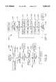
- FIG. 1is a simplified block diagram of the pulse dose and conservation oxygen delivery system in a general embodiment.
- FIG. 2is a chart depicting the flow regulation curve of a piston type oxygen pressure regulator.
- FIG. 3is a block diagram of the complete pulse dose and conservation oxygen delivery system.
- FIG. 4is a block diagram of an alternate embodiment only disclosing a conservation oxygen delivery system.
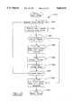
- FIG. 5is a flow chart of the microprocessor control circuit POWER UP subroutine.
- FIG. 6is a flow chart of the microprocessor control circuit INITIALIZATION subroutine.
- FIG. 7is a flow chart of the microprocessor control circuit BATTERY CHARGE subroutine.
- FIG. 8is a flow chart of the microprocessor control circuit REAL TIME INTERRUPT routine.
- FIG. 9is a flow chart of the microprocessor control circuit PULSE TIMER STATUS DETECT subroutine.
- FIG. 10is a flow chart of the microprocessor control circuit LOCK OUT TIMING subroutine.
- FIG. 11is a flow chart of the microprocessor control circuit PULSE TERMINATION subroutine.
- FIG. 12is a flow chart of the microprocessor control circuit HARDWARE DIAGNOSTICS subroutine.
- FIG. 13is a flow chart of the microprocessor control circuit BATTERY RAPID CHARGE subroutine.
- FIG. 14is a flow chart of the microprocessor control circuit CRITICAL FAULT subroutine.
- FIG. 15is a flow chart of the microprocessor control circuit LOW BATTERY FAULT and LOW BATTERY WARNING subroutines.
- FIG. 16is a flow chart of the microprocessor control circuit PULSE FLOW SETTING subroutine.
- FIG. 17is a flow chart of the microprocessor control circuit FILTER BATTERY VOLTAGE subroutine.
- FIG. 18is a flow chart of the microprocessor control circuit MISSING PULSE ALARM subroutine.
- FIG. 19is a flow chart of the microprocessor control circuit INLET PRESSURE AND CALCULATE PULSE PERIOD subroutine.
- the pulse dose and conservation oxygen delivery apparatus 10 of the present inventionis depicted in FIG. 1 in a simplified format.
- the apparatus 10is supplied by oxygen source 2 which could be a wall supply, a compressor or a portable tank. This last option is preferable because one object of the invention is that it be highly portable in order to provide patients with as much freedom as possible.
- Oxygen source 2is then coupled by line 12 to pressure regulator 4 in order to decrease the high pressure of oxygen source 2 to a lower, more manageable pressure.
- any fluid conveying meanssuch as a duct, pipe, channel, or other closed fluid conduit, is referred to as a line.
- Many types of regulatorscould be used such as diaphragm or piston types.
- Typical output pressures used in patient oxygen therapy systemsare 20 psi and 50 psi.
- other regulator output pressurescan be used including nonstandard and variable values.
- Prior art deviceswere limited due to being designed around a particular oxygen source's output pressure.
- the output from pressure regulator 4is constantly monitored by processing unit, such as a micro-controller 8 via feedback from a transducer.
- FIG. 2represents a flow regulation curve showing the output flow of oxygen from a pressure regulator, in this case a piston type, as the inlet pressure to the regulator decreases. This decrease in pressure is associated with the contents of a tank being consumed.
- FIG. 2it should be understood that as the inlet pressure decreases, the output pressure also decreases linearly until an end point is reached at which output pressure falls off sharply.
- This curvedemonstrates the need for constant pressure regulator output monitoring.
- the transduceris represented by a pressure sensor 6 which is coupled by a line 12 coming from the output of the pressure regulator 4.
- the pressure sensor 6provides feedback to the micro-controller 8 as to what the pressure regulator's 4 actual measured output value is in psi.
- Line 12further connects pressure regulator 4 in series with flow selector 14.
- Flow selector 14receives pressurized oxygen and based on its calibration or settings, outputs a volume of oxygen in liters per minute.
- Flow selector 14may be an electro-mechanical device that may be adjusted by a mechanical switch or a potentiometer. It could also be adjusted via the micro-controller 8 with corresponding feedback.
- restrictor 16is a mechanical device which passively limits oxygen passing through at a predetermined maximum pressure. In the embodiment depicted in FIG. 1, restrictor 16 can limit oxygen throughput to approximately 15 L/min. as an example. Restrictor 16 serves as a fail safe mechanism because it is in series with the fail safe oxygen supply path and can limit oxygen pressure to reasonably safe levels without any external power requirements. Pulse dose valve 18 is controlled by micro-controller 8 which controls the valve paths to allow oxygen to flow to the patient during the inhalation phase of breathing and not during the patient's exhalation phase.
- Flow sensor 20allows the micro-controller to determine which breathing phase the patient is in by detecting pressure changes due to inhalation and exhalation. Both oxygen outputs from flow selector 14 and flow sensor 20 are input to fail-safe valve 22, which then is coupled in series by line 12 to bacteria filter 24, and then further coupled to the patient via output port 26. Output port 26 may be connected to a cannula that is inserted into the patient's airway or a face mask that is worn over the patient's nose and mouth for example. Although the preferred embodiments herein show coupling of various components through the feed through line 12, should be understood that the particular arrangement of these components could change.
- FIG. 3A more detailed block diagram of a first embodiment of apparatus 10 is depicted in FIG. 3.
- Micro-controller 8monitors and controls all functions of apparatus 10, as discussed previously.
- Micro-controller 8could be a conventional computer that is equipped with digital and analog inputs and outputs, memory and other supervisory and control circuitry. The apparatus could also be controlled from a personal computer equipped with interface circuitry.
- the micro-controller 8will be an embedded controller equipped with CMOS integrated circuits which facilitates longer battery life due to low current consumption.
- One of the main objectives of the inventionis to provide patients with a highly portable and long lasting oxygen supply. By decreasing circuit power consumption, smaller, more lightweight batteries can be used while still providing power for prolonged periods of time.
- Apparatus 10is supplied electricity via power input 50.
- Power input 50could be any standard power source such as a low voltage AC input that is rectified and regulated at the micro-controller board or it could be 120 VAC that is stepped down and then rectified and regulated. Any conventional power source that results in a low voltage direct current supply capable of powering digital electronics would suffice.
- power input 50is a lightweight, small rechargeable battery.
- Micro-controller 8has several indicators whereby the patient can monitor how the unit is functioning. For example, there may be an audible alarm 40 which is triggered whenever the patient or someone else needs to be aware of an operating or other condition. Such conditions may comprise sensing when a patient stops breathing, when the micro-controller 8 battery charge becomes too low, when oxygen supply 2 drops below safe levels and a plurality of other conditions. A switch 48 may be selectively actuated to turn off the alarm 40 after a predetermined time if desired.
- audible alarm 40there may also be provided in conjunction with audible alarm 40, several visual alarms which the user can use to further identify specific problems in operation of the device. While many indicators for every conceivable condition could be used, the preferred embodiment consists of pulse indicator 46, low battery indicator 44 and missing pulse indicator 42. Any type of visual indicator could be used with low-power LED technology being preferred to once again conserve power and decrease the necessary battery size and weight.
- the deviceis used to monitor breathing of the patient to supply oxygen at the desired time and amount, allowing detection if a patient stops breathing.
- the apparatus 10may then include a means to alert desired personnel of such condition, which may again be an audible or other alarm associated with the apparatus 10, or may alternatively be a means to provide communication of such condition to a remote location.
- the apparatus 10may include a transmitter for communicating this or another condition through air to a remote receiver, which in turn could alert emergency medical personnel or others.
- the patient oxygen output port 26is connected by line 12 to common port 80 of fail-safe valve 22.
- Many types of valvescould be used such as electronic valves, which must be energized continuously while in one state. Pneumatic valves could also be used but in the preferred embodiment, electronic latching valves are contemplated. This option further enhances the low power consumption of the invention because current is supplied at its peak value only to change the state of the valve with a much lower current used to maintain the latched state.
- Fail-safe valve 22is electrically coupled to micro-controller 8 via electrical conductor 52. Although not shown in FIG. 3, it should be understood that power is supplied to all devices, such as valves and pressure transducers, through additional conductors.
- the normally closed port 82 of fail-safe valve 22is coupled by line 12 to common port 86 of pulse dose valve 18.
- Pulse dose valve 18could also be one of many types common in the art, but again an electronic latching valve is preferred.
- Conductor 54couples pulse dose valve 18 to micro-controller 8. Both valves receive electrical signals via their respective conductors directing them to either latch the valve in the normally open position or to release the latch and switch to the normally closed position. If one of the valves is latched in one position, for example the normally open position, then oxygen would pass from the common port through the valve and out the normally open port. If the valve is in the other position then oxygen would flow from the common port and out of the normally closed port.
- Flow/pressure sensor 100is coupled to the normally open port 88 of pulse dose valve 18 and electrically coupled to micro-controller 8 via conductor 56.
- fail-safe valve 22will be in its normally closed position and pulse dose valve 18 will be in its normally open position, as controlled by micro-controller 8.
- pressure sensor 100When the patient begins to inhale, pressure sensor 100 will detect a negative pressure and communicate this to micro-controller 8. Detection of the beginning of the inhalation cycle can be accomplished in many other ways such as replacing pressure sensor 100 with flow sensor 20 as shown in FIG. 1. This arrangement detects when oxygen is pulled through the sensor.
- the flow sensorcould also be repositioned in series with line 12 directly following patient's output port 26 or it could be placed in series between fail-safe valve 22 and pulse dose valve 18, as possible examples.
- a pressure sensor on line 12 coming off the patient output port 26is also contemplated. Any arrangement using either a flow sensor or a pressure sensor that enables micro-controller 8 to detect the start of a patients breathing cycle is suitable for the invention.
- the normally closed port 90 of pulse dose valve 18is coupled by line 12 through restrictor 16 to pressure regulator 4.
- Pressure regulator 4is directly coupled by line 12 to oxygen source 2.
- both the fail-safe valve 22 and the pulse dose valve 18will default to their normally closed positions. This will provide a direct path of oxygen to patient output port 26 from oxygen source 2.
- Restrictor 16will passively limit the amount of oxygen being supplied to the patient at a safe level. This combination allows for an additional level of safety that is necessary with electronic controls. Advanced functions that distinguish this invention from the prior art can be implemented without any sacrifice to the patients safety.
- pressure sensor 6is connected by line 12 to the output of pressure regulator 4.
- Pressure sensor 6supplies feedback to micro-controller 8 via conductor 60.
- Pressure sensor 6is used to monitor the actual output pressure from pressure regulator 4.
- This featureprovides significant advantages as most off the shelf pressure regulators are not very accurate as previously described.
- a diaphragm regulator of 20 psionce connected to a cylinder of oxygen, will typically regulate between 17 psi to 23 psi ( ⁇ 15% tolerance) in output pressure.
- This variancewill directly and proportionally affect the flow rate of oxygen to any device that it is coupled to. This means for example, if a patient is prescribed for 5 L/min. of oxygen, the patient may actually receive anything between 4 L/min. to 6 L/min.
- micro-controller 8can accurately recalculate the pulse dose needed to comply with a prescribed value for oxygen therapy. This value can literally be recalibrated for each and every breath the patient takes, providing near perfect compliance with the prescribed value.
- micro-controller 8To provide the patient with oxygen in pulse doses, the operation of the apparatus 10 initiates micro-controller 8 to first calculate the amount that will be provided to the patient. For every flow setting, a base period of time is precalculated and stored in the micro-controller's 8 non-volatile memory.
- This non-volatile memorypreferably may be EEPROM, NOVRAM, FLASH or any other type of technology that will retain values without power. This base period of time will be referred to as the Base Pulse Period or BPP.
- the BPPis calculated based on pressure within or close to the range of the output pressure of pressure regulator 4. In real time, when the patient is using the device, measurements can be taken during every pause between inhalation cycles when oxygen is not being delivered to the patient or in other intervals if desired.
- micro-controller 8The pressure readings being fed back to micro-controller 8 from pressure sensor 6 are recorded and the difference in the measured pressure and the nominal BPP pressure is used to calculate the Corrected Pulse Period or CPP. With each inhalation taken by the patient, a CPP is calculated and enables micro-controller 8 to switch pulse dose valve 18 to its normally closed port 84, thus supplying oxygen to the patient for a period of time that will deliver the proper fixed volume per breath.
- the Base Pulse Period(referred to as T2) has a duration that at flow rate R2, would deliver at least the same volume of oxygen as would be delivered in a continuous application of oxygen for a duration of T1 at a flow rate less than R2, which will be referred to as R1.
- a TER or compensation error periodis calculated by taking the difference of P2 (the actual time period of the supplied oxygen) and nominal pressure P1 (period of pulse time theoretically calculated and stored in memory). Depending on the value of this difference, the TER value could be negative or positive.
- the Corrected Pulse Periodis calculated by adding the TER value to T2.
- the Corrected Pulse Periodis the length of time the pulse dose valve 18 will allow oxygen to flow to the patient during inhalation at an actual pressure regulator 4 output pressure.
- apparatus 10can also function in a continuous mode rather than pulse dose mode.
- fail-safe valve 22engages to its normally open position and oxygen is supplied continuously at the prescription rate from flow selector 14. This rate is set from remote pulse mode/flow selector 64 which is electrically coupled to flow selector 14 via conductor 62. It is also electrically coupled to micro-controller 8 via conductor 58.
- Remote pulse mode/flow selector 64could be a mechanical switch or a variable potentiometer. It is also contemplated that selector 64 is removed and flow selector 14 is preset directly from micro-controller 8 through user input from a keypad or other common selection device known in the art.
- the continuous modeprovides an additional level of safety above that provided by the fail-safe functions. If the unit loses power or completely malfunctions, both valves will default and provide the patient with a continuous supply of oxygen, but it will only be limited by restrictor 16. The supply will greatly exceed the prescription amount.
- micro-controller 8detects errors only in the pulse dose devices, it can switch to continuous mode which will provide a controlled oxygen flow rate by means of flow selector 14. This also allows for a physician to use the apparatus 10 as a continuous supply if, for medical reasons, he so chooses.
- the method and apparatusmay include in the preferred embodiment, the additional feature of monitoring pressure sensor 6 and keeping track of the number of inhalation cycles and the lengths of time between them, allowing micro-controller 8 to calculate the patient's breathing rate. Once this has been calculated, micro-controller 8 may be used to determine the delay (DL1) in which each inhalation should occur. If an inhalation is not sensed within the duration of a different predetermined period (DL2), micro-controller 8 may initiate the necessary sequence of events described earlier to force a pulse of oxygen to the patient. Predetermined period DL2 may be several times greater in time length than DL1, such as a lapse of time equal to several breaths.
- the pulse of oxygen suppliedmay also extend for n predetermined number of breathing cycles until n multiplied by DL2 is equal to or larger than DL1. Pulses of oxygen may thus be continuously forced to the patient with only a short delay in between each pulse. During the short delays in pulses, micro-controller 8 through flow/pressure sensor 100 checks to see if the patient has resumed breathing and if so it discontinues the forced pulses. Any detected event where the patient stops breathing may also trigger audible alarm 40 to emit a warning, and missing pulse indicator 42 may be illuminated. Again, the apparatus 10 can also communicate this condition to a remote location. Once the warning condition passes, audible alarm 40 and missing pulse indicator 42 turn off.
- FIG. 4represents a conservation oxygen delivery system 110, being similar to the embodiment of FIG. 3 but without the pulse dose elements.
- the apparatus 110functions similar to the description of apparatus 10 in FIG. 3 with regard to detecting the beginning of the patient inhalation phase of breathing.
- fail-safe valve 22is turned on and off by micro-controller 8 to allow for oxygen delivery during inhalation and not during exhalation.
- Flow selector 14delivers a preselected prescription rate of oxygen to the patient whenever fail-safe valve 22 is in its normally closed position.
- continuous supply switch 70has been added which bypasses fail-safe valve 22 altogether.
- Fail-safe valve 22will fail in the position which will allow oxygen to flow to the patient if a malfunction should occur. While not disclosed in FIG. 4 as it is in FIG. 3, a restrictor could be used in series with line 12 to limit the pressure at which oxygen would be supplied in the case of a malfunction.
- FIG. 4also shows restrictor 72 between flow/pressure sensor 20 and line 12 connected to patient output port 26. This is used to prevent high pressures from damaging flow/pressure sensor 20 and the same technique could be employed to place maximum pressure delivery limits on other parts of the equipment and patient.
- micro-controller 8goes through POWER UP 200 subroutine as shown in FIG. 5. It is to be understood that subroutines will be designated as such by being printed in capital letters.
- Micro-controller 8begins by initializing its microprocessor internal control registers 201 which typically aid in memory addressing and basic interface operations. The program memory is then checked for accuracy. Program memory will typically be stored in an EPROM and its checksum value 202 will be calculated and then compared to verify its contents.
- CRITICAL FAULT 204If after comparing the EPROM contents 203, the value does not verify correctly, CRITICAL FAULT 204 will be executed.
- micro-controller 8When CRITICAL FAULT 204, as shown in FIG. 14, is executed, micro-controller 8 disables all of its interrupts 250 to prevent any further functioning of apparatus 10. It then de-energizes and thereby unlatches both pulse dose valve 18 and fail-safe valve 22 which allows for the continuous flow of oxygen to the patient. Finally, micro-controller 8 turns on alarms 254 and enters an endless loop repeating these steps so that no further operation can take place while the patient is being notified of the malfunction. If the EPROM contents do verify correctly then the next step is to test micro-controller's 8 other memory devices, which may comprise of RAM and EEPROM devices for example. This is done by reading and writing to the memory 205 and then comparing the values to see if they are satisfactory at 206. If they are not then CRITICAL FAULT 204 is called. If the memory verification is successful,
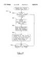
- microprocessor internal timers, I/O ports, and interrupt timersare all initialized at 208 followed by calling HARDWARE DIAGNOSTICS 209, as shown in FIG. 12.
- Micro-controller 8proceeds to test its hardware and if any individual piece fails, an "ERROR" flag 230 is set.
- the pulse dose valve 18 and its driver circuitryis firstly tested at 220, and next fail-safe valve 22 and its driver circuitry is tested at 222.
- the inhalation sensorwhich is flow/pressure sensor 100 in FIG. 3 or flow sensor 20 in FIG. 4, is then checked at 224.
- Pressure sensor 6is tested at 226 and finally audible alarm 40 is checked at 228.
- the hardware diagnostic routineends at 232. If a hardware error is reported at 214, then CRITICAL FAULT 204 is entered, wherein program execution will halt and apparatus 10 will default to its fail-safe mode. If no hardware error is detected then it will proceed to initialize its real time interrupt 210, detect the pulse flow setting 211 corresponding to the flow selector 14 and then call MEASURE INLET PRESSURE AND CALCULATE PULSE PERIOD 212. Once this subroutine is completed, BATTERY CHARGE 213 is called.
- MEASURE INLET PRESSURE AND CALCULATE PULSE PERIOD 212begins by determining if apparatus 10 is in the process of delivering a pulse of oxygen at 260. If it is then the subroutine ends at 268. If it is not delivering a pulse of oxygen at 260, the inlet pressure is measured several times by pressure sensor 6 and then its mean value is calculated at 262. The next step is to retrieve the predetermined "Base Pulse Period" value from microcontroller's 8 non-volatile memory at 264. Finally, the "Corrected Pulse Period" is calculated at 266 and the subroutine then returns at 268.
- BATTERY CHARGE 213, as shown in FIG. 7,is called which immediately enters BATTERY RAPID CHARGE 270, as shown in FIG. 13.
- This subroutinebegins by reading the pulse dose flow selector 14 setting and then calling MEASURE INLET PRESSURE AND CALCULATE PULSE PERIOD 212, described in FIG. 19.
- micro-controller 8checks to see if apparatus 10 is being powered by a battery charger/adaptor 282. If not, the unit turns off its high current charge relays 290 to prevent damage to apparatus 10. If it is being powered by a battery charger/adaptor then FILTER BATTERY VOLTAGE 400 is executed, as shown in FIG. 17.
- This routinesimply checks to see if the unit is pulsing oxygen, if not it will continue to check until it is at 402. Once this has been done, micro-controller 8 will measure its battery voltage numerous times at 404 and use those measurements to calculate the average battery voltage at 406. Finally the subroutine will return at 408. Upon returning to BATTERY RAPID CHARGE 270, in FIG. 13, the unit will calculate the charge slope 286 needed to recharge its battery. If the slope is not negative 288, then it will loop to the start and repeat until a negative slope is calculated, which indicates the battery is fully charged. At this point the high current charge relay 290 and indicators will be turned off and the subroutine will end 292.
- micro-controller 8reads the pulse flow selector reading 272, calls MEASURE INLET PRESSURE AND CALCULATE PULSE PERIOD 212, and resets micro-controller's 8 watch dog timer 274.
- the watch dog timeris used to make sure the unit is functioning and if not, reset it rather than have it lock up in a continuous faulty loop.
- the unitthen checks its battery by calling FILTER BATTERY VOLTAGE 400, followed by PULSE FLOW SETTING 340, as shown in FIG. 16.
- PULSE FLOW SETTING 340begins by determining the setting of the pulse flow selector 341 and then it calculates where in its EEPROM memory the "Base Pulse Period" value is stored 342 and then loads this value into a storage register within the microprocessor 343. It then returns to BATTERY CHARGE 213. Finally micro-controller 8 checks to see if any error flags have been detected at 276. If so CRITICAL FAULT 204 is entered and if not it will loop back and check for the pulse flow selector setting at 272.
- micro-controller 8Upon receiving an interrupt signal from flow/pressure sensor 100 indicating that the patient has begun the inhalation phase of breathing, micro-controller 8 will stop whatever it is currently doing and execute REAL TIME INTERRUPT 500, as shown in FIG. 8. It first checks to see if the battery charge is critically low at 502 and if it is LOW BATTERY FAULT 510 is called. If the battery is not at a critically low charge value, it next determines if the charge is low at 504 even though not critical. If so then LOW BATTERY WARNING 520 is called. If not micro-controller 8 determines whether the real time interrupt was actually caused by the patient beginning inhalation 506 or if it was a false signal.
- LOW BATTERY FAULT 510in FIG. 15, shuts down all power to the unit causing it to automatically enter the fail-safe mode and continuously supply oxygen to the patient at 511.
- LOW BATTERY WARNING 520in FIG. 15, turns on audible alarm 40 for a predetermined length of time and then repeats this several times at 522. It then returns from the subroutine 524.
- PULSE TIMER STATUS DETECT 508shown in FIG. 9, starts by determining if the pulse timer is currently turned on or off at 530. It further checks to see if apparatus 10 is delivering a pulse of oxygen at 532. Whether it is or not, essentially the same test is performed next. In each case diagnostics are run on fail-safe valve 22, pulse dose valve 18, and both valve's driver circuitry. The only difference is that if the unit was delivering oxygen when the diagnostics began, pulse dose valve 18 should be on at 534. If the unit was not delivering oxygen, then pulse dose valve 18 should be off at 536. If the unit was delivering oxygen and the valves and drivers are working at 538, micro-controller 8 calls PULSE TERMINATION 600.
- micro-controller 8calls LOCK OUT TIMING 650. If in either case the valves or drivers were not functioning then CRITICAL FAULT 204 is entered and the unit shuts down into its fail-safe mode.
- apparatus 10enters PULSE TERMINATION 600, shown in FIG. 11, it first checks to see if the pulse period has expired at 602, and if not it readjusts its internal pulse timers at 604 and exits from the real time interrupt call at 606. If the pulse period did expire at 602, then pulse dose valve 100 is closed and a variable called the "Load Lockout Timer" is initialized at 608 and then the real time interrupt is ended at 606.
- apparatus 10enters LOCK OUT TIMING 650, as shown in FIG. 10, it first checks to see if a lock out period is currently in progress at 652. If so, the lock out timer is adjusted at 654 and the real time interrupt ends at 606. If the unit was not in a lock out period at 652, then it is determined if patient inhalation has begun.
- the lock out timeris used to keep the system from interrupting the patient's oxygen supply if the patient is in the middle of inhaling. This feature adds a software fail-safe to ensure that the patient receives all the oxygen necessary and prevents electronic interference and glitches, common to microprocessor technology, from interrupting the patient.
- the unitbegins to deliver a pulse of oxygen to the patient at 662.
- apparatus 10enters the subroutine CALCULATE PATIENT'S BREATHING RATE 654, which uses the detection of inhalation via flow/pressure sensor 100 and clocking signals generated by micro-controller 8. After the patients breathing rate is determined and stored in micro-controller's 8 memory, it returns from the real-time interrupt at 606. If the inhalation phase was not detected at 656, the unit uses the previous measurement of the patients breathing rate to determine if any pulses of oxygen have been missed at 658, which would indicate that the patient has stopped breathing. If a pulse has not been missed at 658, the unit will return from the real-time interrupt at 606. If a pulse was missed, MISSING PULSE ALARM 700 is called. If the unit returns from this subroutine, it will then exit from the real-time interrupt at 606.
- MISSING PULSE ALARM 700begins by forcing a predetermined number of oxygen pulses every "n" seconds at 702, being a preselected value. It then checks to see if the patient has begun to breath on their own at 704. If so the subroutine exits at 710. If not, the unit turns on missing pulse indicator 42 and audible alarm 40. The unit then resets its pulse timers so that the pulse doses of oxygen are delivered at the patient's previously determined normal breathing rate 708 and the subroutine exits at 710.
- micro-controller 8By adding additional memory to micro-controller 8, a log containing the date of treatment, the length of treatment, the patient's breathing rate over time, the rate of actual oxygen consumption and pressure decrease, the time of any warnings or malfunctions and what they were, and many other valuable information could be provided. Such information could be used for patient or apparatus monitoring and could be stored and retrieved at any time. The retrieval could be to a personal computer via a serial or parallel data link or apparatus 10 could be equipped with a modem or a cellular modem for remote monitoring. This would be highly advantageous today with the trend toward home health care. Instead of incurring the high cost of hospital stays, patients could be monitored at their homes. If critical warnings, such as when the patient stops breathing, are detected micro-controller 8 could automatically dial emergency personnel.
- Micro-controller 8could also be equipped with additional outputs that simply make or break connections, such as through relays. These could be used to send signals to other medical equipment if certain conditions are established. This would also provide flexibility in that apparatus 10 would be able to interface to currently nonexistent technology that may be developed in the future and that may benefit the patient.
Landscapes
- Health & Medical Sciences (AREA)
- Pulmonology (AREA)
- Emergency Medicine (AREA)
- Biomedical Technology (AREA)
- Engineering & Computer Science (AREA)
- Anesthesiology (AREA)
- Heart & Thoracic Surgery (AREA)
- Hematology (AREA)
- Life Sciences & Earth Sciences (AREA)
- Animal Behavior & Ethology (AREA)
- General Health & Medical Sciences (AREA)
- Public Health (AREA)
- Veterinary Medicine (AREA)
- Otolaryngology (AREA)
- Respiratory Apparatuses And Protective Means (AREA)
Abstract
Description
This invention relates to an oxygen delivery apparatus and method for operating the same. This invention relates particularly to pulse dose and conservation delivery of oxygen in accurate amounts as would be prescribe by a physician.
Oxygen delivery systems have been developed for providing supplemental oxygen therapy for a variety of diseases or conditions, such as chronic obstructive pulmonary disease (COPD), respiratory conditions or other medical conditions which require increased oxygen supply to the patient. Supplemental oxygen therapy can be provided using stationary liquid oxygen systems which require a patient to remain stationary during the therapy, which may be required for extended periods of time. Although providing desired therapeutic characteristics, such approaches are undesirable, because they do not allow a patient to have freedom of travel and to function relatively normally. There thus have been developed portable oxygen systems, using small lightweight cylinders of oxygen gas, with offering ambulatory oxygen patients an improve alternative to stationary liquid oxygen systems. Historically, in such portable oxygen systems, oxygen has been supplied to medical patients in a continuous flow, usually administered with cannula or a face mask. Because the human body only needs oxygen during the inhalation phase of the respiratory cycle, oxygen is wasted during the exhalation cycle. This waste of oxygen was also a problem for emergency medical personnel. Ambulatory services were forced to carry larger oxygen tanks that took up limited space and had to be replenished more often. This took time and forced health care professionals to incur unnecessary costs, which in the end were passed on to the patient. In addition, constant exposure to the flow of oxygen tends to dry a patient's nasal passages, causing discomfort and irritation. Due to this, prior art devices were required to humidify the oxygen before it was delivered to the patient which required additional steps and mechanisms at additional costs.
Because of these deficiencies, oxygen conservation devices were developed which deliver oxygen only during the inhalation phase of the respiratory cycle. Generally, these devices function by opening an oxygen supply valve during inhalation and closing the valve during exhalation. These devices drastically reduced the amount of wasted oxygen which meant that smaller, more lightweight tanks could be used.
One important deficiency that still exists in the prior art is that oxygen pressure is assumed to be constant. A high pressure tank of oxygen is fed to a pressure regulator usually designed to output a fixed pressure, typically 20 psi or 50 psi. As the oxygen is depleted from the tank, its pressure will decrease and these fluctuations coupled with less than accurate characteristics of most regulators, results in patients not receiving exact prescribed amounts of oxygen. In addition, calibration of prior art devices is based on the output of the pressure regulator, either 20 psi or 50 psi. Different pressure regulators are not interchangeable without modification to the oxygen delivery controls.
Also in known oxygen delivery systems, a problem has existed in that if the pressure regulator or other components of the delivery system fail, oxygen may not be properly supplied to the patient as required. Such an occurrence could result in a dangerous condition, as the oxygen supply to the patient may be cutoff or may be inadequate for providing the prescribed rate of oxygen required by the patient.
Thus, based upon the foregoing, the performance of oxygen conservation devices or pulse does devices are generally limited by the performance of the available pressure regulators used as a part thereof. As an example, a typical pressure regulator may be a diaphragm regulator, which will regulate oxygen supply within a tolerance band of the regulator, with the output pressure of the regulator affecting the flow rate of oxygen proportionally, such that the supply of oxygen is not constant and precise according to a prescribed oxygen requirement for a particular patient. In the example of a diaphragm regulator, the regulated pressure output may be selected to be 20 psi, with the actual amount of oxygen delivered varying between 17 psi to 23 psi assuming a plus or minus 15% tolerance in the regulator. In such an example, if a patient is prescribed 5 L/min. of oxygen, the patient may receive anywhere between 4 L/min. to 6 L/min. of oxygen, depending on the pressure of the source of compressed oxygen gas. In another aspect, oxygen delivery systems provide a predetermined volume of oxygen per period of time for an inhalation phase of the respiratory cycle. Such an approach assumes that the oxygen required by the patient remains constant, not accounting for changes in the breathing cycle of the patient.
Therefore, in light of the foregoing deficiencies in prior art oxygen delivery systems, a need exists for an oxygen delivery system which can deliver precise doses of oxygen to a patient in a prescribed amount regardless of characteristics of a pressure regulator or changes in the patients respiratory cycle.
Based upon the foregoing, it is an object of the present invention is to provide a pulse dose or conservation oxygen delivery system and method of operating the same wherein oxygen pressure is continually adjusted to provide an accurate output despite inaccuracies induced by conventional regulators and pressure changes due to oxygen tank consumption.
Another object of this invention is to conserve oxygen by supplying it during the inhalation phase of breathing and not during the exhalation phase. Demand is triggered by a patient beginning the inhalation phase. This conservation may be further enhanced by only delivering doses of oxygen during the first half of the inhalation cycle.
A further object of this invention is to provide a fail safe feature that will function irrespective of a malfunction in any electronic or mechanical controls. If the pulse dose delivery control malfunctions, oxygen will be continuously delivered to the patient at a prescription rate or other predetermined rate. If the oxygen delivery system malfunctions altogether, the invention also provides supply valves which will fail in a fashion that will allow for a continuous flow of oxygen.
Yet a further object of this invention is to detect if a patient stops breathing for a predetermined amount of time and if so, force pulses of oxygen to the patient while signalling medical personnel through a series of audible, visual or other alarms, either locally or remotely.
Another objective is to reduce the weight and size of the oxygen supply apparatus while increasing the length of time it can operate thus providing the patient with significantly more freedom to travel and function normally in society.
In the present invention, various embodiments of pulse dose and conservation oxygen delivery systems are provided which overcome the deficiencies in the prior art respiratory gas delivery systems. In the preferred embodiment, the respiratory gas delivery system includes a control circuit, which is typically microprocessor based, monitors a differential pressure sensor coupled to a patient interface such as a cannula or a face mask. When a patient inhales, a negative pressure is detected at the patient interface point. This condition is sensed and an electrical signal corresponding to the condition is sent to the control circuit. The control circuit processes the signal and then energizes a valve, through driver circuitry, that connects the patient to the oxygen supply for a fixed period of time at a preselected amount. The control circuit continually monitors the pressure differentials at the patient interface and only delivers pulses of oxygen upon inhalation of the patient. Oxygen delivery is based on a fixed volume of oxygen per breath which provides the advantage of a varying net volume being delivered to the patient per period of time depending on and proportional to their respiratory rate. Thus, if a patient exercises and their breathing rate increases, the control circuit will automatically and proportional to the breathing rate, increase the net volume of oxygen being delivered. In addition if the control circuit fails to sense patient inhalation for a predetermined period of time, it will automatically force pulses of oxygen to the patient while signalling this emergency condition to others. Further, if the control circuit malfunctions or the unit loses power it will fail in such a way that it will still supply a continuous flow of oxygen to the patient, providing an extra level of safety.
The above objects and advantages of the present invention will become more readily apparent from a reading of the detailed description of preferred embodiments taken in conjunction with the drawings, wherein:
FIG. 1 is a simplified block diagram of the pulse dose and conservation oxygen delivery system in a general embodiment.
FIG. 2 is a chart depicting the flow regulation curve of a piston type oxygen pressure regulator.
FIG. 3 is a block diagram of the complete pulse dose and conservation oxygen delivery system.
FIG. 4 is a block diagram of an alternate embodiment only disclosing a conservation oxygen delivery system.
FIG. 5 is a flow chart of the microprocessor control circuit POWER UP subroutine.
FIG. 6 is a flow chart of the microprocessor control circuit INITIALIZATION subroutine.
FIG. 7 is a flow chart of the microprocessor control circuit BATTERY CHARGE subroutine.
FIG. 8 is a flow chart of the microprocessor control circuit REAL TIME INTERRUPT routine.
FIG. 9 is a flow chart of the microprocessor control circuit PULSE TIMER STATUS DETECT subroutine.
FIG. 10 is a flow chart of the microprocessor control circuit LOCK OUT TIMING subroutine.
FIG. 11 is a flow chart of the microprocessor control circuit PULSE TERMINATION subroutine.
FIG. 12 is a flow chart of the microprocessor control circuit HARDWARE DIAGNOSTICS subroutine.
FIG. 13 is a flow chart of the microprocessor control circuit BATTERY RAPID CHARGE subroutine.
FIG. 14 is a flow chart of the microprocessor control circuit CRITICAL FAULT subroutine.
FIG. 15 is a flow chart of the microprocessor control circuit LOW BATTERY FAULT and LOW BATTERY WARNING subroutines.
FIG. 16 is a flow chart of the microprocessor control circuit PULSE FLOW SETTING subroutine.
FIG. 17 is a flow chart of the microprocessor control circuit FILTER BATTERY VOLTAGE subroutine.
FIG. 18 is a flow chart of the microprocessor control circuit MISSING PULSE ALARM subroutine.
FIG. 19 is a flow chart of the microprocessor control circuit INLET PRESSURE AND CALCULATE PULSE PERIOD subroutine.
The pulse dose and conservationoxygen delivery apparatus 10 of the present invention is depicted in FIG. 1 in a simplified format. Theapparatus 10 is supplied byoxygen source 2 which could be a wall supply, a compressor or a portable tank. This last option is preferable because one object of the invention is that it be highly portable in order to provide patients with as much freedom as possible.Oxygen source 2 is then coupled byline 12 topressure regulator 4 in order to decrease the high pressure ofoxygen source 2 to a lower, more manageable pressure. As used herein, any fluid conveying means, such as a duct, pipe, channel, or other closed fluid conduit, is referred to as a line. Many types of regulators could be used such as diaphragm or piston types.
Typical output pressures used in patient oxygen therapy systems are 20 psi and 50 psi. As will be explained, in the present invention, other regulator output pressures can be used including nonstandard and variable values. Prior art devices were limited due to being designed around a particular oxygen source's output pressure. In the present invention, the output frompressure regulator 4 is constantly monitored by processing unit, such as amicro-controller 8 via feedback from a transducer. The need for this constant monitoring is demonstrated by FIG. 2 which represents a flow regulation curve showing the output flow of oxygen from a pressure regulator, in this case a piston type, as the inlet pressure to the regulator decreases. This decrease in pressure is associated with the contents of a tank being consumed. As shown in FIG. 2, it should be understood that as the inlet pressure decreases, the output pressure also decreases linearly until an end point is reached at which output pressure falls off sharply. This curve demonstrates the need for constant pressure regulator output monitoring.
In FIG. 1, the transducer is represented by apressure sensor 6 which is coupled by aline 12 coming from the output of thepressure regulator 4. In this embodiment, thepressure sensor 6 provides feedback to themicro-controller 8 as to what the pressure regulator's 4 actual measured output value is in psi.Line 12 further connectspressure regulator 4 in series withflow selector 14.Flow selector 14 receives pressurized oxygen and based on its calibration or settings, outputs a volume of oxygen in liters per minute.Flow selector 14 may be an electro-mechanical device that may be adjusted by a mechanical switch or a potentiometer. It could also be adjusted via themicro-controller 8 with corresponding feedback.
Also coupled byline 12 topressure regulator 4 is restrictor 16,pulse dose valve 18, and flowsensor 20 all in series with each other.Restrictor 16 is a mechanical device which passively limits oxygen passing through at a predetermined maximum pressure. In the embodiment depicted in FIG. 1, restrictor 16 can limit oxygen throughput to approximately 15 L/min. as an example.Restrictor 16 serves as a fail safe mechanism because it is in series with the fail safe oxygen supply path and can limit oxygen pressure to reasonably safe levels without any external power requirements.Pulse dose valve 18 is controlled bymicro-controller 8 which controls the valve paths to allow oxygen to flow to the patient during the inhalation phase of breathing and not during the patient's exhalation phase.Flow sensor 20 allows the micro-controller to determine which breathing phase the patient is in by detecting pressure changes due to inhalation and exhalation. Both oxygen outputs fromflow selector 14 andflow sensor 20 are input to fail-safe valve 22, which then is coupled in series byline 12 to bacteria filter 24, and then further coupled to the patient viaoutput port 26.Output port 26 may be connected to a cannula that is inserted into the patient's airway or a face mask that is worn over the patient's nose and mouth for example. Although the preferred embodiments herein show coupling of various components through the feed throughline 12, should be understood that the particular arrangement of these components could change.
A more detailed block diagram of a first embodiment ofapparatus 10 is depicted in FIG. 3. Micro-controller 8 monitors and controls all functions ofapparatus 10, as discussed previously.Micro-controller 8 could be a conventional computer that is equipped with digital and analog inputs and outputs, memory and other supervisory and control circuitry. The apparatus could also be controlled from a personal computer equipped with interface circuitry. In the preferred embodiment, themicro-controller 8 will be an embedded controller equipped with CMOS integrated circuits which facilitates longer battery life due to low current consumption. One of the main objectives of the invention is to provide patients with a highly portable and long lasting oxygen supply. By decreasing circuit power consumption, smaller, more lightweight batteries can be used while still providing power for prolonged periods of time.Apparatus 10 is supplied electricity viapower input 50.Power input 50 could be any standard power source such as a low voltage AC input that is rectified and regulated at the micro-controller board or it could be 120 VAC that is stepped down and then rectified and regulated. Any conventional power source that results in a low voltage direct current supply capable of powering digital electronics would suffice. In the preferredembodiment power input 50 is a lightweight, small rechargeable battery.
There may also be provided in conjunction withaudible alarm 40, several visual alarms which the user can use to further identify specific problems in operation of the device. While many indicators for every conceivable condition could be used, the preferred embodiment consists ofpulse indicator 46, low battery indicator 44 and missing pulse indicator 42. Any type of visual indicator could be used with low-power LED technology being preferred to once again conserve power and decrease the necessary battery size and weight. As previously mentioned, the device is used to monitor breathing of the patient to supply oxygen at the desired time and amount, allowing detection if a patient stops breathing. Theapparatus 10 may then include a means to alert desired personnel of such condition, which may again be an audible or other alarm associated with theapparatus 10, or may alternatively be a means to provide communication of such condition to a remote location. For example, theapparatus 10 may include a transmitter for communicating this or another condition through air to a remote receiver, which in turn could alert emergency medical personnel or others.
Also shown in FIG. 3, the patientoxygen output port 26 is connected byline 12 tocommon port 80 of fail-safe valve 22. Many types of valves could be used such as electronic valves, which must be energized continuously while in one state. Pneumatic valves could also be used but in the preferred embodiment, electronic latching valves are contemplated. This option further enhances the low power consumption of the invention because current is supplied at its peak value only to change the state of the valve with a much lower current used to maintain the latched state. Fail-safe valve 22 is electrically coupled tomicro-controller 8 viaelectrical conductor 52. Although not shown in FIG. 3, it should be understood that power is supplied to all devices, such as valves and pressure transducers, through additional conductors. The normally closed port 82 of fail-safe valve 22 is coupled byline 12 tocommon port 86 ofpulse dose valve 18.Pulse dose valve 18 could also be one of many types common in the art, but again an electronic latching valve is preferred.Conductor 54 couples pulsedose valve 18 tomicro-controller 8. Both valves receive electrical signals via their respective conductors directing them to either latch the valve in the normally open position or to release the latch and switch to the normally closed position. If one of the valves is latched in one position, for example the normally open position, then oxygen would pass from the common port through the valve and out the normally open port. If the valve is in the other position then oxygen would flow from the common port and out of the normally closed port. Flow/pressure sensor 100 is coupled to the normallyopen port 88 ofpulse dose valve 18 and electrically coupled tomicro-controller 8 viaconductor 56.
During normal operation, fail-safe valve 22 will be in its normally closed position andpulse dose valve 18 will be in its normally open position, as controlled bymicro-controller 8. In this arrangement, there will be a direct path frompatient output port 26 topressure sensor 100. When the patient begins to inhale,pressure sensor 100 will detect a negative pressure and communicate this tomicro-controller 8. Detection of the beginning of the inhalation cycle can be accomplished in many other ways such as replacingpressure sensor 100 withflow sensor 20 as shown in FIG. 1. This arrangement detects when oxygen is pulled through the sensor. The flow sensor could also be repositioned in series withline 12 directly following patient'soutput port 26 or it could be placed in series between fail-safe valve 22 andpulse dose valve 18, as possible examples. Use of a pressure sensor online 12 coming off thepatient output port 26 is also contemplated. Any arrangement using either a flow sensor or a pressure sensor that enablesmicro-controller 8 to detect the start of a patients breathing cycle is suitable for the invention. The normally closedport 90 ofpulse dose valve 18 is coupled byline 12 throughrestrictor 16 topressure regulator 4.Pressure regulator 4 is directly coupled byline 12 tooxygen source 2. As can now be seen, if the apparatus fails or loses power, both the fail-safe valve 22 and thepulse dose valve 18 will default to their normally closed positions. This will provide a direct path of oxygen topatient output port 26 fromoxygen source 2.Restrictor 16 will passively limit the amount of oxygen being supplied to the patient at a safe level. This combination allows for an additional level of safety that is necessary with electronic controls. Advanced functions that distinguish this invention from the prior art can be implemented without any sacrifice to the patients safety.
To further implement the novel features of this invention,pressure sensor 6 is connected byline 12 to the output ofpressure regulator 4.Pressure sensor 6 supplies feedback tomicro-controller 8 viaconductor 60.Pressure sensor 6 is used to monitor the actual output pressure frompressure regulator 4. This feature provides significant advantages as most off the shelf pressure regulators are not very accurate as previously described. As an example, a diaphragm regulator of 20 psi, once connected to a cylinder of oxygen, will typically regulate between 17 psi to 23 psi (±15% tolerance) in output pressure. This variance will directly and proportionally affect the flow rate of oxygen to any device that it is coupled to. This means for example, if a patient is prescribed for 5 L/min. of oxygen, the patient may actually receive anything between 4 L/min. to 6 L/min. of oxygen. By monitoring the actual pressure being output bypressure regulator 4 rather than assuming it at the regulators rated value,micro-controller 8 can accurately recalculate the pulse dose needed to comply with a prescribed value for oxygen therapy. This value can literally be recalibrated for each and every breath the patient takes, providing near perfect compliance with the prescribed value.
To provide the patient with oxygen in pulse doses, the operation of theapparatus 10 initiatesmicro-controller 8 to first calculate the amount that will be provided to the patient. For every flow setting, a base period of time is precalculated and stored in themicro-controller's 8 non-volatile memory. This non-volatile memory preferably may be EEPROM, NOVRAM, FLASH or any other type of technology that will retain values without power. This base period of time will be referred to as the Base Pulse Period or BPP. The BPP is calculated based on pressure within or close to the range of the output pressure ofpressure regulator 4. In real time, when the patient is using the device, measurements can be taken during every pause between inhalation cycles when oxygen is not being delivered to the patient or in other intervals if desired. The pressure readings being fed back tomicro-controller 8 frompressure sensor 6 are recorded and the difference in the measured pressure and the nominal BPP pressure is used to calculate the Corrected Pulse Period or CPP. With each inhalation taken by the patient, a CPP is calculated and enablesmicro-controller 8 to switchpulse dose valve 18 to its normally closed port 84, thus supplying oxygen to the patient for a period of time that will deliver the proper fixed volume per breath.
The method of determining the fixed volume of gas per breath will now be discussed further. When a physician prescribes an amount of oxygen for a patient, he will do so at a constant oxygen flow rate (referred to as R2) such that the volume of oxygen needed to be supplied in a breath can be delivered in less than half of the normal inhalation cycle. This is done because only the first half of the inhalation cycle oxygenates the blood. A typical time value for this delivery period is approximately 0.5 seconds (referred to as T1). Once the physician has setapparatus 10 for a specified flow rate and started the unit,micro-controller 8 throughpressure sensor 6 will determine the exact pressure output bypressure regulator 4.Micro-controller 8 will next read from its memory the Base Pulse Period value corresponding to the selected flow rate. The Base Pulse Period (referred to as T2) has a duration that at flow rate R2, would deliver at least the same volume of oxygen as would be delivered in a continuous application of oxygen for a duration of T1 at a flow rate less than R2, which will be referred to as R1. At this point, a TER or compensation error period is calculated by taking the difference of P2 (the actual time period of the supplied oxygen) and nominal pressure P1 (period of pulse time theoretically calculated and stored in memory). Depending on the value of this difference, the TER value could be negative or positive. Finally, the Corrected Pulse Period is calculated by adding the TER value to T2. The Corrected Pulse Period is the length of time thepulse dose valve 18 will allow oxygen to flow to the patient during inhalation at anactual pressure regulator 4 output pressure.
If selected by the user, or if electronic malfunctions are detected in the pulse dose features of the invention,apparatus 10 can also function in a continuous mode rather than pulse dose mode. In a continuous mode, fail-safe valve 22 engages to its normally open position and oxygen is supplied continuously at the prescription rate fromflow selector 14. This rate is set from remote pulse mode/flow selector 64 which is electrically coupled to flowselector 14 viaconductor 62. It is also electrically coupled tomicro-controller 8 via conductor 58. Remote pulse mode/flow selector 64 could be a mechanical switch or a variable potentiometer. It is also contemplated thatselector 64 is removed and flowselector 14 is preset directly frommicro-controller 8 through user input from a keypad or other common selection device known in the art. The continuous mode provides an additional level of safety above that provided by the fail-safe functions. If the unit loses power or completely malfunctions, both valves will default and provide the patient with a continuous supply of oxygen, but it will only be limited byrestrictor 16. The supply will greatly exceed the prescription amount. With the continuous mode feature, ifmicro-controller 8 detects errors only in the pulse dose devices, it can switch to continuous mode which will provide a controlled oxygen flow rate by means offlow selector 14. This also allows for a physician to use theapparatus 10 as a continuous supply if, for medical reasons, he so chooses.
Due to the advanced features ofapparatus 10 it also provides further safety for patients by monitoring whether or not they continue to breathe. The method and apparatus may include in the preferred embodiment, the additional feature ofmonitoring pressure sensor 6 and keeping track of the number of inhalation cycles and the lengths of time between them, allowingmicro-controller 8 to calculate the patient's breathing rate. Once this has been calculated,micro-controller 8 may be used to determine the delay (DL1) in which each inhalation should occur. If an inhalation is not sensed within the duration of a different predetermined period (DL2),micro-controller 8 may initiate the necessary sequence of events described earlier to force a pulse of oxygen to the patient. Predetermined period DL2 may be several times greater in time length than DL1, such as a lapse of time equal to several breaths. The pulse of oxygen supplied may also extend for n predetermined number of breathing cycles until n multiplied by DL2 is equal to or larger than DL1. Pulses of oxygen may thus be continuously forced to the patient with only a short delay in between each pulse. During the short delays in pulses,micro-controller 8 through flow/pressure sensor 100 checks to see if the patient has resumed breathing and if so it discontinues the forced pulses. Any detected event where the patient stops breathing may also triggeraudible alarm 40 to emit a warning, and missing pulse indicator 42 may be illuminated. Again, theapparatus 10 can also communicate this condition to a remote location. Once the warning condition passes,audible alarm 40 and missing pulse indicator 42 turn off. It is also envisioned as an additional safety feature that even if the missing breath pulse condition passes that the missing pulse indicator 42 would change from a continuously illuminated state to a flashing state. This would allow medical personnel to know that a patient had stopped breathing at some earlier point in time, although the medical personnel were not present. This may provide an important patient diagnostic feature. Although the foregoing features relating to the detection of any breathing cycle events relate to the preferred embodiment, the implementation of monitoring the breathing cycle by other methods is contemplated.
FIG. 4 represents a conservationoxygen delivery system 110, being similar to the embodiment of FIG. 3 but without the pulse dose elements. Theapparatus 110 functions similar to the description ofapparatus 10 in FIG. 3 with regard to detecting the beginning of the patient inhalation phase of breathing. Because there is no pulse dose valve in this embodiment, fail-safe valve 22 is turned on and off bymicro-controller 8 to allow for oxygen delivery during inhalation and not during exhalation.Flow selector 14 delivers a preselected prescription rate of oxygen to the patient whenever fail-safe valve 22 is in its normally closed position. In this particular embodiment, continuous supply switch 70 has been added which bypasses fail-safe valve 22 altogether. This allows the device to function as a continuous flow oxygen supply when needed or when wasted consumption is not critical, for example when the device is connected to a compressor or some other virtual source of oxygen. Fail-safe valve 22 will fail in the position which will allow oxygen to flow to the patient if a malfunction should occur. While not disclosed in FIG. 4 as it is in FIG. 3, a restrictor could be used in series withline 12 to limit the pressure at which oxygen would be supplied in the case of a malfunction.
FIG. 4 also shows restrictor 72 between flow/pressure sensor 20 andline 12 connected topatient output port 26. This is used to prevent high pressures from damaging flow/pressure sensor 20 and the same technique could be employed to place maximum pressure delivery limits on other parts of the equipment and patient.
A significant aspect of the present invention is in its control and monitoring of its devices and the patient, which are all accomplished throughmicro-controller 8, the operation of which will now be further explained. In the preferred embodiment, when the apparatus has power applied to it by turning it on,micro-controller 8 goes throughPOWER UP 200 subroutine as shown in FIG. 5. It is to be understood that subroutines will be designated as such by being printed in capital letters.Micro-controller 8 begins by initializing its microprocessor internal control registers 201 which typically aid in memory addressing and basic interface operations. The program memory is then checked for accuracy. Program memory will typically be stored in an EPROM and itschecksum value 202 will be calculated and then compared to verify its contents. If after comparing theEPROM contents 203, the value does not verify correctly,CRITICAL FAULT 204 will be executed. WhenCRITICAL FAULT 204, as shown in FIG. 14, is executed,micro-controller 8 disables all of its interrupts 250 to prevent any further functioning ofapparatus 10. It then de-energizes and thereby unlatches bothpulse dose valve 18 and fail-safe valve 22 which allows for the continuous flow of oxygen to the patient. Finally,micro-controller 8 turns onalarms 254 and enters an endless loop repeating these steps so that no further operation can take place while the patient is being notified of the malfunction. If the EPROM contents do verify correctly then the next step is to testmicro-controller's 8 other memory devices, which may comprise of RAM and EEPROM devices for example. This is done by reading and writing to thememory 205 and then comparing the values to see if they are satisfactory at 206. If they are not thenCRITICAL FAULT 204 is called. If the memory verification is successful, then INITIALIZATION 207 is executed.
In FIG. 6, once POWER UP is completed, the microprocessor internal timers, I/O ports, and interrupt timers are all initialized at 208 followed by callingHARDWARE DIAGNOSTICS 209, as shown in FIG. 12. Micro-controller 8 proceeds to test its hardware and if any individual piece fails, an "ERROR" flag 230 is set. In thepulse dose apparatus 10, thepulse dose valve 18 and its driver circuitry is firstly tested at 220, and next fail-safe valve 22 and its driver circuitry is tested at 222. The inhalation sensor which is flow/pressure sensor 100 in FIG. 3 or flowsensor 20 in FIG. 4, is then checked at 224.Pressure sensor 6 is tested at 226 and finallyaudible alarm 40 is checked at 228. Once all hardware has tested positive or an error flag has been set, the hardware diagnostic routine ends at 232. If a hardware error is reported at 214, thenCRITICAL FAULT 204 is entered, wherein program execution will halt andapparatus 10 will default to its fail-safe mode. If no hardware error is detected then it will proceed to initialize its real time interrupt 210, detect the pulse flow setting 211 corresponding to theflow selector 14 and then call MEASURE INLET PRESSURE AND CALCULATEPULSE PERIOD 212. Once this subroutine is completed,BATTERY CHARGE 213 is called.
MEASURE INLET PRESSURE AND CALCULATEPULSE PERIOD 212, as shown in FIG. 19, begins by determining ifapparatus 10 is in the process of delivering a pulse of oxygen at 260. If it is then the subroutine ends at 268. If it is not delivering a pulse of oxygen at 260, the inlet pressure is measured several times bypressure sensor 6 and then its mean value is calculated at 262. The next step is to retrieve the predetermined "Base Pulse Period" value from microcontroller's 8 non-volatile memory at 264. Finally, the "Corrected Pulse Period" is calculated at 266 and the subroutine then returns at 268.
Upon receiving an interrupt signal from flow/pressure sensor 100 indicating that the patient has begun the inhalation phase of breathing,micro-controller 8 will stop whatever it is currently doing and execute REAL TIME INTERRUPT 500, as shown in FIG. 8. It first checks to see if the battery charge is critically low at 502 and if it isLOW BATTERY FAULT 510 is called. If the battery is not at a critically low charge value, it next determines if the charge is low at 504 even though not critical. If so thenLOW BATTERY WARNING 520 is called. If not micro-controller 8 determines whether the real time interrupt was actually caused by thepatient beginning inhalation 506 or if it was a false signal. If the signal was accurate, a flag is set in memory pointing this out. After that PULSE TIMER STATUS DETECT 508 is called.LOW BATTERY FAULT 510, in FIG. 15, shuts down all power to the unit causing it to automatically enter the fail-safe mode and continuously supply oxygen to the patient at 511.LOW BATTERY WARNING 520, in FIG. 15, turns onaudible alarm 40 for a predetermined length of time and then repeats this several times at 522. It then returns from thesubroutine 524.
PULSE TIMER STATUS DETECT 508, shown in FIG. 9, starts by determining if the pulse timer is currently turned on or off at 530. It further checks to see ifapparatus 10 is delivering a pulse of oxygen at 532. Whether it is or not, essentially the same test is performed next. In each case diagnostics are run on fail-safe valve 22,pulse dose valve 18, and both valve's driver circuitry. The only difference is that if the unit was delivering oxygen when the diagnostics began,pulse dose valve 18 should be on at 534. If the unit was not delivering oxygen, then pulsedose valve 18 should be off at 536. If the unit was delivering oxygen and the valves and drivers are working at 538,micro-controller 8calls PULSE TERMINATION 600. If the unit was not delivering oxygen and the valves and drivers are working at 540,micro-controller 8 calls LOCK OUTTIMING 650. If in either case the valves or drivers were not functioning thenCRITICAL FAULT 204 is entered and the unit shuts down into its fail-safe mode.
Ifapparatus 10 entersPULSE TERMINATION 600, shown in FIG. 11, it first checks to see if the pulse period has expired at 602, and if not it readjusts its internal pulse timers at 604 and exits from the real time interrupt call at 606. If the pulse period did expire at 602, then pulsedose valve 100 is closed and a variable called the "Load Lockout Timer" is initialized at 608 and then the real time interrupt is ended at 606.
Ifapparatus 10 enters LOCK OUTTIMING 650, as shown in FIG. 10, it first checks to see if a lock out period is currently in progress at 652. If so, the lock out timer is adjusted at 654 and the real time interrupt ends at 606. If the unit was not in a lock out period at 652, then it is determined if patient inhalation has begun. The lock out timer is used to keep the system from interrupting the patient's oxygen supply if the patient is in the middle of inhaling. This feature adds a software fail-safe to ensure that the patient receives all the oxygen necessary and prevents electronic interference and glitches, common to microprocessor technology, from interrupting the patient. If the inhalation phase is detected, the unit begins to deliver a pulse of oxygen to the patient at 662. At this point,apparatus 10 enters the subroutine CALCULATE PATIENT'SBREATHING RATE 654, which uses the detection of inhalation via flow/pressure sensor 100 and clocking signals generated bymicro-controller 8. After the patients breathing rate is determined and stored inmicro-controller's 8 memory, it returns from the real-time interrupt at 606. If the inhalation phase was not detected at 656, the unit uses the previous measurement of the patients breathing rate to determine if any pulses of oxygen have been missed at 658, which would indicate that the patient has stopped breathing. If a pulse has not been missed at 658, the unit will return from the real-time interrupt at 606. If a pulse was missed, MISSINGPULSE ALARM 700 is called. If the unit returns from this subroutine, it will then exit from the real-time interrupt at 606.
While the above software operations of a preferred embodiment have been described in detail, it should be noted that due to the nature and versatility of software, the implementation of the subroutine calls may be performed in a variety of fashions contemplated within the invention, and use of the subroutines is also selective and variable. The underlying steps of the process used to implement the pulse dose and conservation delivery of oxygen are the important and novel aspects of the invention. Also, due to the flexibility of computer technology several other functions are contemplated as additional features. For example, a complete breathing rate and alarm condition log may be provided. By adding additional memory tomicro-controller 8, a log containing the date of treatment, the length of treatment, the patient's breathing rate over time, the rate of actual oxygen consumption and pressure decrease, the time of any warnings or malfunctions and what they were, and many other valuable information could be provided. Such information could be used for patient or apparatus monitoring and could be stored and retrieved at any time. The retrieval could be to a personal computer via a serial or parallel data link orapparatus 10 could be equipped with a modem or a cellular modem for remote monitoring. This would be highly advantageous today with the trend toward home health care. Instead of incurring the high cost of hospital stays, patients could be monitored at their homes. If critical warnings, such as when the patient stops breathing, are detectedmicro-controller 8 could automatically dial emergency personnel. This type of instantaneous information management would improve the odds of a patient surviving an emergency.Micro-controller 8 could also be equipped with additional outputs that simply make or break connections, such as through relays. These could be used to send signals to other medical equipment if certain conditions are established. This would also provide flexibility in thatapparatus 10 would be able to interface to currently nonexistent technology that may be developed in the future and that may benefit the patient. Although preferred embodiments of the invention have been described, various modifications would occur to those skilled in the art, and are contemplated in the invention. Accordingly, modifications may be made without departing from the scope of the invention, and it is intended to claim all modifications and variations as fall within the scope of the invention as defined in the appended claims.
Claims (34)
1. A gas delivery apparatus consisting essentially of
a gas pressure regulator, having an input and an output, with said input selectively coupled to a gas supply source;
a pressure sensor coupled to said output of said gas pressure regulator for sensing fluidic supply pressure emitted from said output of said pressure regulator;
at least one gas valve, having an input and an output, with said input of said at least one gas valve fluidically coupled to said output of said pressure regulator downstream of said pressure sensor;
a control system for controlling said at least one gas valve and communicating with said pressure sensor; and
an output port coupled to said output of said at least one gas valve.
2. The gas delivery apparatus as recited in claim 1, further comprising a gas flow selection valve coupled between said pressure regulator and said at least one gas valve to further limit gas supplied to said output port.
3. The gas delivery apparatus as recited in claim 1, further comprising a fluidic switch coupled from said input to said output of said at least one gas valve, allowing said at least one gas valve to be manually overridden to allow gas to be supplied continuously to said output port.
4. The gas delivery apparatus as recited in claim 1, further comprising;
a second gas valve, having an input and an output, said second gas valve coupled between said output of said at least one gas valve and said output port, said second gas valve controlled by said control system.
5. The gas delivery apparatus as recited in claim 4, wherein said at least one gas valve and said second gas valve each has a common port, a normally-closed port, and a normally-open port, wherein said at least one gas valve and said second gas valve each operate to default to said normally-open port which allows communication of gas between said normally-open port and said common port.
6. The gas delivery apparatus as recited in claim 5, further comprising a gas flow selection valve, having an input and an output, said input of said gas flow selection valve coupled to said output of said pressure regulator and said output of said gas flow selection valve coupled to said second gas valve.
7. The gas delivery apparatus as recited in claim 6, wherein
said output of said gas flow selection valve is coupled to said normally-open port of said second gas valve,
said common port of said at least one gas valve is coupled to said normally-closed port of said second gas valve,
said common port of said second gas valve is coupled to said output port, and
said normally-closed port of said at least one gas valve is coupled to said output of said pressure regulator.
8. The gas delivery apparatus as recited in claim 2, further comprising a remote gas flow selector, said remote gas flow selector being coupled to said gas flow selection valve and to said control system and operating to adjust the gas flow of said gas flow selection valve.
9. The gas delivery apparatus as recited in claim 1, further comprising a plurality of visual indicators operated by said control system for indicating status conditions of said apparatus.
10. The gas delivery apparatus as recited in claim 1, further comprising an audible transducer electrically coupled to said control system for signalling status conditions of said apparatus.
11. The gas delivery apparatus as recited in claim 1, wherein,
said control system includes at least one sensor to detect the breathing cycle of a patient to whom gas is delivered by means of said output port, and controls operation of said at least one gas valve to supply gas to said output port.
12. The gas delivery apparatus as recited in claim 11, wherein,
said control system controls operation of said at least one gas valve to supply gas to said output port at predetermined intervals.
13. The gas delivery apparatus as recited in claim 12, wherein,
said gas is supplied to said output port during an inhalation phase of said breathing cycle.
14. The gas delivery apparatus as recited in claim 12, wherein,
said gas is supplied to said output port substantially continuously during said breathing cycle.
15. The gas delivery apparatus as recited in claim 11, wherein,
said control system controls operation of said at least one gas valve to supply gas to said output port in a predetermined amount.
16. The gas delivery apparatus as recited in claim 11, wherein,
said control system monitors said breathing cycle and controls operation of said at least one gas valve to supply gas to said output port upon detecting an abnormality in said breathing cycle.
17. A method of delivering a respiratory gas to a patient comprising the steps of:
providing a portable gas delivery system comprising a gas pressure regulator having an input and an output, with the input selectively coupled to a gas supply source, a pressure sensor coupled to said output of the gas pressure regulator for sensing fluidic supply pressure emitted from the output of the pressure regulator, at least one gas supply valve having an input and output, with the input of the at least one gas valve fluidically coupled to the output of the pressure regulator downstream of the pressure sensor, a control system for controlling the at least one gas valve and communicating with the pressure sensor, and an output port coupled to the output of the at least one gas valve:
supplying a gas at a controllable pressure and predetermined flow rate from said gas supply source to the at least one gas supply valve;
monitoring the breathing cycle of a patient;
measuring the volume of said supply gas through said at least one gas supply valve; and controlling said at least one gas supply valve to supply a predetermined volume of gas to said patient at predetermined times according to said breathing cycle.
18. The method as in claim 17, further comprising the steps of:
monitoring the breathing pressure of said patient;
supplying gas to said patient upon detecting a decrease in pressure due to inhalation, and
stop the supply of gas upon detecting a return to ambient or a greater pressure due to the inhalation cycle ending.
19. The method as in claim 17, further comprising the steps of:
setting said supply gas to a constant flow rate such that the volume of gas needed in a breath can be delivered within approximately half of a inhalation cycle;
measuring the actual pressure of said supply gas;
calculate the time period necessary to provide said supply gas for in order to deliver the desired volume of said supply gas at a predetermined nominal pressure;
calculate the compensation time period to compensate for the difference in said predetermined nominal pressure and said actual pressure by determining the difference in said pressures and adding this value to said predetermined nominal pressure; and
deliver gas supplied at the actual pressure for a time period equal to said predetermined nominal pressure time period plus said compensation time period.
20. The method as in claim 17, further comprising the steps of:
detecting the start of a plurality of inhalation cycles and calculating a breathing rate;
calculating a time period in which said inhalation cycle must begin based on said breathing rate;
comparing the lapse of time since said previous inhalation cycle to determine if said inhalation cycle has not begun within said time period;
supplying gas upon detecting that said inhalation cycle has not begun within said time period.
21. A portable gas delivery apparatus comprising:
a gas pressure regulator, having an input and an output, with said input selectively coupled to a gas supply source;
a pressure sensor coupled to said output of said gas pressure regulator for sensing fluidic supply pressure emitted from said output of said pressure regulator;
at least one gas valve, having an input and an output, with said input of said at least one gas valve fluidically coupled to said output of said pressure regulator downstream of said pressure sensor;
a control system for controlling said at least one gas valve and communicating with said pressure sensor; and
an output port coupled to said output of said at least on gas valve;
wherein the gas delivery apparatus is portable with a user.
22. The apparatus of claim 21 wherein said gas supply source is a portable pressurized tank.
23. The apparatus of claim 21, further comprising a gas flow selection valve coupled between said pressure regulator and said at least on gas valve to further limit gas supplied to said output port.
24. The apparatus as recited in claim 21, further comprising a fluidic switch coupled from said input to said output of said at least one gas valve, allowing said at least one gas valve to be manually overridden to allow gas to be supplied continuously to said output port.
25. The apparatus of claim 21, further comprising:
a second gas valve, having an input and an output, said second gas valve coupled between said output of said at least one gas valve and said output port, said second gas valve controlled by said control system.
26. The apparatus of claim 25, wherein said at least on gas valve and said second gas valve each has a common port, a normally-closed port, and a normally-open port, wherein said at least one gas valve and said second gas valve each operated to default to said normally-open port which allows communication of gas between said normally-open port and said common port.
27. The apparatus of claim 26, further comprising a gas flow selection valve, having an input and an output, said input of said gas flow selection valve coupled to said output of said pressure regulator and said output of said gas flow selection valve coupled to said second gas valve, wherein said output of said gas flow selection valve is coupled to said normally-open port of said second gas valve,
said common port of said at least one gas valve is coupled to said normally-closed port of said second gas valve;
said common port of said second gas valve is coupled to said output port; and
said normally-closed port of said at least one gas valve is coupled to said output of said pressure regulator.
28. The apparatus of claim 23, further comprising a remote gas flow selector, said remote gas flow selector being coupled to said gas flow selection valve and to said control system and operating to adjust the gas flow of said gas flow selection valve.
29. The apparatus of claim 21, further comprising at least one indicator operated by said control system for indicating at least on status condition of said apparatus.
30. The apparatus of claim 21, wherein
said control system includes at least one sensor to detect the breathing cycle of a patient to whom gas is delivered by means of said output port, and controls operation of said at least one gas valve to supply gas to said output port.
31. The apparatus of claim 21, wherein
said control system controls operation of said at least one gas valve to supply gas to said output port at predetermined intervals.
32. The apparatus of claim 21, wherein
said control system includes at least one sensor to detect the breathing cycle of a patient, and controls operation of said at least one gas valve, wherein said gas is supplied to said output port during an inhalation phase of said breathing cycle.
33. The apparatus of claim 21, wherein
said control system controls operation of said at least one gas valve to supply gas to said output port in a predetermined amount.
34. The apparatus of claim 21, wherein
said control system monitors said breathing cycle and controls operation of said at least one gas valve to supply gas to said output port upon detecting an abnormality in said breathing cycle.
Priority Applications (1)
| Application Number | Priority Date | Filing Date | Title |
|---|---|---|---|
| US08/514,675US5603315A (en) | 1995-08-14 | 1995-08-14 | Multiple mode oxygen delivery system |
Applications Claiming Priority (1)
| Application Number | Priority Date | Filing Date | Title |
|---|---|---|---|
| US08/514,675US5603315A (en) | 1995-08-14 | 1995-08-14 | Multiple mode oxygen delivery system |
Publications (1)
| Publication Number | Publication Date |
|---|---|
| US5603315Atrue US5603315A (en) | 1997-02-18 |
Family
ID=24048229
Family Applications (1)
| Application Number | Title | Priority Date | Filing Date |
|---|---|---|---|
| US08/514,675Expired - Fee RelatedUS5603315A (en) | 1995-08-14 | 1995-08-14 | Multiple mode oxygen delivery system |
Country Status (1)
| Country | Link |
|---|---|
| US (1) | US5603315A (en) |
Cited By (147)
| Publication number | Priority date | Publication date | Assignee | Title |
|---|---|---|---|---|
| US5839434A (en)* | 1993-11-16 | 1998-11-24 | Invacare Corporation | Method and apparatus for dispensing respiratory gases |
| US5865174A (en)* | 1996-10-29 | 1999-02-02 | The Scott Fetzer Company | Supplemental oxygen delivery apparatus and method |
| US5875783A (en)* | 1997-04-09 | 1999-03-02 | Dragerwerk Ag | Gas delivery means for respirators and anesthesia apparatus |
| US5881725A (en)* | 1997-08-19 | 1999-03-16 | Victor Equipment Company | Pneumatic oxygen conserver |
| EP0878208A3 (en)* | 1997-05-16 | 1999-08-25 | Ohmeda Inc. | Constant volume nitric oxide pulse delivery device |
| EP0879612A3 (en)* | 1997-05-16 | 1999-11-03 | Datex-Ohmeda, Inc. | Purge system for nitric oxide administration apparatus |
| WO1999061090A1 (en)* | 1998-05-22 | 1999-12-02 | Duke University | Method and apparatus for supplemental oxygen delivery |
| EP0937479A3 (en)* | 1998-02-18 | 2000-07-19 | Datex-Ohmeda, Inc. | Nitric oxide administration device with timed pulse |
| EP0960630A3 (en)* | 1998-05-26 | 2000-07-26 | Datex-Ohmeda Inc. | Accurate dose nitric oxide pulse delivery device with monitoring and alarms |
| US6119723A (en) | 1997-02-14 | 2000-09-19 | Resmed Limited, | Apparatus for varying the flow area of a conduit |
| US6131572A (en)* | 1998-05-20 | 2000-10-17 | Instrumentarium Oy | Medical dosing device having dosing chamber with a pressure sensor |
| US6142149A (en)* | 1997-10-23 | 2000-11-07 | Steen; Scot Kenneth | Oximetry device, open oxygen delivery system oximetry device and method of controlling oxygen saturation |
| US6220244B1 (en) | 1998-09-15 | 2001-04-24 | Mclaughlin Patrick L. | Conserving device for use in oxygen delivery and therapy |
| US6237594B1 (en)* | 1999-09-22 | 2001-05-29 | Salter Labs | Pneumatically-operated gas demand apparatus |
| US6253764B1 (en) | 1996-05-08 | 2001-07-03 | Resmed, Ltd. | Control of delivery pressure in CPAP treatment or assisted respiration |
| US6269811B1 (en) | 1998-11-13 | 2001-08-07 | Respironics, Inc. | Pressure support system with a primary and a secondary gas flow and a method of using same |
| US6364161B1 (en) | 2000-09-27 | 2002-04-02 | Victor Equipment Company | Oxygen conserver |
| US20020038657A1 (en)* | 2000-09-21 | 2002-04-04 | Ngk Spark Plug Co., Ltd. | Oxygen supply apparatus, controller for the oxygen supply apparatus, and recording medium for the controller |
| US6371114B1 (en) | 1998-07-24 | 2002-04-16 | Minnesota Innovative Technologies & Instruments Corporation | Control device for supplying supplemental respiratory oxygen |
| US6394088B1 (en)* | 1998-11-06 | 2002-05-28 | Mark R. Frye | Oxygen-delivery system with portable oxygen meter |
| US20020168322A1 (en)* | 1998-10-09 | 2002-11-14 | Andrew Clark | Flow resistance modulated aerosolized active agent delivery |
| US20020195106A1 (en)* | 2001-06-19 | 2002-12-26 | Mitsuru Uchiyama | Apparatus for supplying a therapeutic oxygen gas |
| US6532957B2 (en) | 1996-09-23 | 2003-03-18 | Resmed Limited | Assisted ventilation to match patient respiratory need |
| US6532958B1 (en) | 1997-07-25 | 2003-03-18 | Minnesota Innovative Technologies & Instruments Corporation | Automated control and conservation of supplemental respiratory oxygen |
| US20030140924A1 (en)* | 2001-11-06 | 2003-07-31 | Aylsworth Alonzo C. | Therapeutic gas conserver and control |
| FR2835188A1 (en)* | 2002-01-28 | 2003-08-01 | Bear Medical | DEVICE FOR CONTROLLING AND REGULATING THE FLOW OF OXYGEN ADAPTED TO THE PHYSIOLOGICAL NEEDS OF THE PATIENT |
| US20030150455A1 (en)* | 2001-10-19 | 2003-08-14 | Bliss Peter L. | Self-calibrating supplemental oxygen delivery system |
| US20030168057A1 (en)* | 2001-12-14 | 2003-09-11 | Inhale Therapeutic Systems, Inc. | Electronically controllable aerosol delivery |
| US6619285B2 (en)* | 2001-06-13 | 2003-09-16 | Albert D. Hawkins, Jr. | Ambient air breathing device |
| US20030189492A1 (en)* | 2002-04-04 | 2003-10-09 | Harvie Mark R. | Monitoring, alarm and automatic adjustment system for users of oxygen and compressed air |
| US6655379B2 (en)* | 1998-03-16 | 2003-12-02 | Nektar Therapeutics | Aerosolized active agent delivery |
| US20040079359A1 (en)* | 2002-10-24 | 2004-04-29 | Aylsworth Alonzo C. | Method and system for delivery of therapeutic gas to a patient and for filling a cylinder |
| US20040200477A1 (en)* | 2003-03-26 | 2004-10-14 | Christian Bleys | Portable assembly for emergency ventilation |
| US6837243B1 (en)* | 2003-09-30 | 2005-01-04 | Scott Technologies, Inc. | Automatic transfer regulator for hose-line respirator |
| US20050072298A1 (en)* | 2003-10-07 | 2005-04-07 | Deane Geoffrey Frank | Portable gas fractionalization system |
| US20050072426A1 (en)* | 2003-10-07 | 2005-04-07 | Deane Geoffrey Frank | Portable gas fractionalization system |
| US20050072423A1 (en)* | 2003-10-07 | 2005-04-07 | Deane Geoffrey Frank | Portable gas fractionalization system |
| US20050072306A1 (en)* | 2003-10-07 | 2005-04-07 | Deane Geoffrey Frank | Portable gas fractionalization system |
| US20050092321A1 (en)* | 2003-10-29 | 2005-05-05 | Airmatrix Technologies, Inc. | Method and system of sensing airflow and delivering therapeutic gas to a patient |
| US20050103342A1 (en)* | 2003-11-14 | 2005-05-19 | Jorczak Kevin D. | Remote control gas regulation system |
| US20050103341A1 (en)* | 2003-10-07 | 2005-05-19 | Deane Geoffrey F. | Portable gas fractionalization system |
| US20050121033A1 (en)* | 1998-02-25 | 2005-06-09 | Ric Investments, Llc. | Respiratory monitoring during gas delivery |
| US20050130086A1 (en)* | 2003-12-01 | 2005-06-16 | Macnutt Rob | Burner ignition and control system |
| KR100496410B1 (en)* | 2001-08-06 | 2005-06-17 | 주식회사 옥서스 | Oxy generator having a state monitoring/communication function and remote supervision system |
| US20050192538A1 (en)* | 2004-02-26 | 2005-09-01 | Voege James A. | Method and apparatus for regulating fluid flow or conserving fluid flow |
| US20050217668A1 (en)* | 2003-10-24 | 2005-10-06 | Pulmonox Technologies Corporation | System and elements for managing therapeutic gas administration to a spontaneously breathing non-ventilated patient |
| US20050274381A1 (en)* | 2004-06-04 | 2005-12-15 | Deane Geoffrey F | Systems and methods for delivering therapeutic gas to patients |
| US20060048781A1 (en)* | 2002-12-17 | 2006-03-09 | Hideo Nawata | Oxygen supply apparatus |
| US20060118115A1 (en)* | 2004-12-08 | 2006-06-08 | James Cannon | Oxygen conservation system for commercial aircraft |
| US20060157058A1 (en)* | 2005-01-18 | 2006-07-20 | Acoba, Llc | Trans-fill method and system |
| US20060169281A1 (en)* | 2005-02-03 | 2006-08-03 | Aylsworth Alonzo C | Continuous flow selective delivery of therapeutic gas |
| US20060219245A1 (en)* | 2005-04-01 | 2006-10-05 | Holder Gary N | Gas conserving device |
| US20070044799A1 (en)* | 2005-07-08 | 2007-03-01 | Hete Bernie F | Modular oxygen regulator system and respiratory treatment system |
| US20070135757A1 (en)* | 2005-12-12 | 2007-06-14 | Acker Jaron M | Multiple lumen monitored drug delivery nasal cannula system |
| EP1800707A1 (en)* | 2005-12-22 | 2007-06-27 | General Electric Company | Integrated ventilator nasal trigger and gas monitoring system |
| FR2896697A1 (en)* | 2006-02-01 | 2007-08-03 | Air Liquide | DEVICE FOR DELIVERING APPROPRIATE RESPIRATORY OXYGEN QUALITY |
| US20070214955A1 (en)* | 2006-03-16 | 2007-09-20 | Acoba, L.L.C. | Method and system of coordinating an intensifier and sieve beds |
| US20070214960A1 (en)* | 2006-03-16 | 2007-09-20 | Acoba, L.L.C. | Method and system of operating a trans-fill device |
| US20080053441A1 (en)* | 2006-09-01 | 2008-03-06 | Nellcor Puritan Bennett Incorporated | Method and system of detecting faults in a breathing assistance device |
| US20080135044A1 (en)* | 2003-06-18 | 2008-06-12 | Breathe Technologies | Methods and devices for minimally invasive respiratory support |
| US20080173303A1 (en)* | 2007-01-19 | 2008-07-24 | Mclaughlin Patrick L | Capacitive sensor |
| US20080190429A1 (en)* | 2005-03-02 | 2008-08-14 | Integral Orthopedics Inc. | Conserving Device for Breathable Gas |
| US20080216838A1 (en)* | 2003-08-18 | 2008-09-11 | Menlo Lifesciences, Llc | Method and device for non-invasive ventilation with nasal interface |
| US7448594B2 (en) | 2004-10-21 | 2008-11-11 | Ameriflo, Inc. | Fluid regulator |
| US20090065007A1 (en)* | 2007-09-06 | 2009-03-12 | Wilkinson William R | Oxygen concentrator apparatus and method |
| US20090151719A1 (en)* | 2004-02-04 | 2009-06-18 | Breathe Technologies, Inc. | Methods and devices for treating sleep apnea |
| US20090183739A1 (en)* | 2008-01-18 | 2009-07-23 | Menlolife, Inc. | Methods and devices for improving efficacy of non-invasive ventilation |
| US20090188499A1 (en)* | 2008-01-30 | 2009-07-30 | Chekal Michael P | Method and apparatus for customizing delivery of an oxygen-enriched gas to a user |
| US20090199855A1 (en)* | 2004-11-01 | 2009-08-13 | Davenport James M | System and method for conserving oxygen delivery while maintaining saturation |
| US20090205493A1 (en)* | 2008-02-20 | 2009-08-20 | Thompson Loren M | Method of removing water from an inlet region of an oxygen generating system |
| US20090205494A1 (en)* | 2008-02-20 | 2009-08-20 | Mcclain Michael S | Single manifold assembly for oxygen-generating systems |
| US20090211443A1 (en)* | 2008-02-21 | 2009-08-27 | Youngblood James H | Self-serviceable filter for an oxygen generating device |
| US20090211438A1 (en)* | 2008-02-21 | 2009-08-27 | Thompson Loren M | Method of determining the purity of oxygen present in an oxygen-enriched gas produced from an oxygen delivery system |
| US20090212962A1 (en)* | 2008-02-22 | 2009-08-27 | Delphi Technologies, Inc. | Oxygen Generating System with Self-Contained Electronic Diagnostics and Fault-Tolerant Operation |
| US20090214370A1 (en)* | 2008-02-22 | 2009-08-27 | Delphi Technologies, Inc. | Damping apparatus for scroll compressors for oxygen-generating systems |
| US20090214393A1 (en)* | 2008-02-22 | 2009-08-27 | Chekal Michael P | Method of generating an oxygen-enriched gas for a user |
| US20090229460A1 (en)* | 2008-03-13 | 2009-09-17 | Mcclain Michael S | System for generating an oxygen-enriched gas |
| US20090260625A1 (en)* | 2003-06-18 | 2009-10-22 | Breathe Technologies, Inc. | Methods, systems and devices for improving ventilation in a lung area |
| FR2930165A1 (en)* | 2008-04-21 | 2009-10-23 | Air Liquide | DEVICE FOR DETECTING PATIENT OBSERVANCE OF OXYGEN THERAPY TREATMENT |
| US7617826B1 (en) | 2004-02-26 | 2009-11-17 | Ameriflo, Inc. | Conserver |
| USD606655S1 (en) | 2008-06-27 | 2009-12-22 | Inova Labs, Llc | Portable oxygen concentrator |
| US20090314296A1 (en)* | 2008-06-23 | 2009-12-24 | Be Intellectual Property, Inc. | system for regulating the dispensing of commercial aircraft passenger oxygen supply |
| US20100043786A1 (en)* | 2006-05-18 | 2010-02-25 | Breathe Technologies | Tracheostoma spacer, tracheotomy method, and device for inserting a tracheostoma spacer |
| US20100052922A1 (en)* | 2008-05-28 | 2010-03-04 | Alexander Roger Deas | Rebreather oxygen risk alarm |
| US7686870B1 (en) | 2005-12-29 | 2010-03-30 | Inogen, Inc. | Expandable product rate portable gas fractionalization system |
| US20100252037A1 (en)* | 2009-04-02 | 2010-10-07 | Breathe Technologies, Inc. | Methods, systems and devices for non-invasive open ventilation with gas delivery nozzles within nasal pillows |
| US20100252043A1 (en)* | 2003-08-11 | 2010-10-07 | Breathe Technologies, Inc. | Method and arrangement for respiratory support for a patient airway prosthesis and catheter |
| US20100252046A1 (en)* | 2007-07-06 | 2010-10-07 | Dahlstroem Bo | Expiratory valve of an anesthetic breathing apparatus having safety backup |
| US20100269834A1 (en)* | 2003-08-11 | 2010-10-28 | Breathe Technologies, Inc. | Systems, methods and apparatus for respiratory support of a patient |
| US20100300444A1 (en)* | 2008-05-28 | 2010-12-02 | Ipg, Llc | Oxygen conserving oxygen delivery system |
| WO2011007346A1 (en)* | 2009-06-09 | 2011-01-20 | Respinova Ltd. | Device and methods for applying therapeutic protocols to organs of the cardiopulmonary system |
| US20110247620A1 (en)* | 2010-04-07 | 2011-10-13 | Chart Sequal Technologies Inc. | Portable Oxygen Delivery Device |
| WO2011130367A1 (en)* | 2010-04-13 | 2011-10-20 | Obenchain Valerie A | Gas flow and pressure error alarm |
| US20120000464A1 (en)* | 2009-03-18 | 2012-01-05 | Ognjen Gajic | Ventilator Monitoring and Control |
| WO2012024342A1 (en)* | 2010-08-16 | 2012-02-23 | Breathe Technologies, Inc. | Methods, systems and devices using lox to provide ventilatory support |
| US20120174563A1 (en)* | 2009-09-10 | 2012-07-12 | Peugeot Citroen Automobiles Sa | Device and Method for Regulating the Injection of a Quantity of Reducer in the Gaseous Phase |
| US8302602B2 (en) | 2008-09-30 | 2012-11-06 | Nellcor Puritan Bennett Llc | Breathing assistance system with multiple pressure sensors |
| US20130152933A1 (en)* | 2010-08-10 | 2013-06-20 | The Regents Of The University Of California, A California Corporation | Automated fluid delivery system and method |
| US8567399B2 (en) | 2007-09-26 | 2013-10-29 | Breathe Technologies, Inc. | Methods and devices for providing inspiratory and expiratory flow relief during ventilation therapy |
| US8603228B2 (en) | 2010-09-07 | 2013-12-10 | Inova Labs, Inc. | Power management systems and methods for use in an oxygen concentrator |
| US8616207B2 (en) | 2010-09-07 | 2013-12-31 | Inova Labs, Inc. | Oxygen concentrator heat management system and method |
| US8677999B2 (en) | 2008-08-22 | 2014-03-25 | Breathe Technologies, Inc. | Methods and devices for providing mechanical ventilation with an open airway interface |
| CN103800975A (en)* | 2012-11-14 | 2014-05-21 | 深圳迈瑞生物医疗电子股份有限公司 | Fluid flow control system with integrated manual fluid flow controls and method thereof |
| CN103809622A (en)* | 2012-11-13 | 2014-05-21 | 深圳迈瑞生物医疗电子股份有限公司 | Electrically controlled flow control system and method with mechanical control as standby |
| WO2014078528A1 (en)* | 2012-11-14 | 2014-05-22 | Mindray Ds Usa, Inc. | Electronic and manual backup flow control systems |
| US8770193B2 (en) | 2008-04-18 | 2014-07-08 | Breathe Technologies, Inc. | Methods and devices for sensing respiration and controlling ventilator functions |
| US8770199B2 (en) | 2012-12-04 | 2014-07-08 | Ino Therapeutics Llc | Cannula for minimizing dilution of dosing during nitric oxide delivery |
| US8776793B2 (en) | 2008-04-18 | 2014-07-15 | Breathe Technologies, Inc. | Methods and devices for sensing respiration and controlling ventilator functions |
| US8844526B2 (en) | 2012-03-30 | 2014-09-30 | Covidien Lp | Methods and systems for triggering with unknown base flow |
| US8939152B2 (en) | 2010-09-30 | 2015-01-27 | Breathe Technologies, Inc. | Methods, systems and devices for humidifying a respiratory tract |
| US20150059738A1 (en)* | 2013-09-04 | 2015-03-05 | Microbaric Oxygen Systems, Llc | Hyperoxic therapy systems, methods and apparatus |
| US9132250B2 (en) | 2009-09-03 | 2015-09-15 | Breathe Technologies, Inc. | Methods, systems and devices for non-invasive ventilation including a non-sealing ventilation interface with an entrainment port and/or pressure feature |
| US9283348B2 (en) | 2012-11-14 | 2016-03-15 | Shenzhen Mindray Bio-Medical Electronics Co., Ltd | Electronic and manual backup flow control systems |
| US9364624B2 (en) | 2011-12-07 | 2016-06-14 | Covidien Lp | Methods and systems for adaptive base flow |
| US9440180B2 (en) | 2012-10-12 | 2016-09-13 | Inova Labs, Llc | Oxygen concentrator systems and methods |
| US9440179B2 (en) | 2014-02-14 | 2016-09-13 | InovaLabs, LLC | Oxygen concentrator pump systems and methods |
| US9440036B2 (en) | 2012-10-12 | 2016-09-13 | InovaLabs, LLC | Method and systems for the delivery of oxygen enriched gas |
| US9498589B2 (en) | 2011-12-31 | 2016-11-22 | Covidien Lp | Methods and systems for adaptive base flow and leak compensation |
| US9717876B2 (en) | 2012-10-12 | 2017-08-01 | Inova Labs, Inc. | Dual oxygen concentrator systems and methods |
| US9795756B2 (en) | 2012-12-04 | 2017-10-24 | Mallinckrodt Hospital Products IP Limited | Cannula for minimizing dilution of dosing during nitric oxide delivery |
| US9808591B2 (en) | 2014-08-15 | 2017-11-07 | Covidien Lp | Methods and systems for breath delivery synchronization |
| US20170368295A1 (en)* | 2016-06-22 | 2017-12-28 | University Of Dammam | Nebulizer tubing and a nebulizer system |
| US9925346B2 (en) | 2015-01-20 | 2018-03-27 | Covidien Lp | Systems and methods for ventilation with unknown exhalation flow |
| US9950129B2 (en) | 2014-10-27 | 2018-04-24 | Covidien Lp | Ventilation triggering using change-point detection |
| US9962512B2 (en) | 2009-04-02 | 2018-05-08 | Breathe Technologies, Inc. | Methods, systems and devices for non-invasive ventilation including a non-sealing ventilation interface with a free space nozzle feature |
| US9981096B2 (en) | 2013-03-13 | 2018-05-29 | Covidien Lp | Methods and systems for triggering with unknown inspiratory flow |
| US10058668B2 (en) | 2007-05-18 | 2018-08-28 | Breathe Technologies, Inc. | Methods and devices for sensing respiration and providing ventilation therapy |
| US10105505B2 (en) | 2012-01-13 | 2018-10-23 | Respinova Ltd. | Means and method for fluid pulses |
| WO2019063744A1 (en)* | 2017-09-29 | 2019-04-04 | Koninklijke Philips N.V. | Pressure support device and method of providing an alert for non-effective pressure compensation regimen |
| US10252020B2 (en) | 2008-10-01 | 2019-04-09 | Breathe Technologies, Inc. | Ventilator with biofeedback monitoring and control for improving patient activity and health |
| JP2019122813A (en)* | 2012-06-29 | 2019-07-25 | レスメド・プロプライエタリー・リミテッド | Pressure sensor evaluation of respirator |
| US10751500B2 (en)* | 2011-11-30 | 2020-08-25 | Oxus Co., Ltd. | Apparatus and method for oxygen delivery |
| US10760700B2 (en) | 2018-10-03 | 2020-09-01 | Larry Boggs | Oxygen flow remote-control assembly |
| WO2020178600A1 (en)* | 2019-03-07 | 2020-09-10 | Bpr Medical Limited | Gas flow alarm |
| US10792449B2 (en) | 2017-10-03 | 2020-10-06 | Breathe Technologies, Inc. | Patient interface with integrated jet pump |
| CN111921050A (en)* | 2020-08-19 | 2020-11-13 | 华氧医疗科技(大连)有限公司 | A method for controlling oxygen delivery |
| US20210316162A1 (en)* | 2020-04-09 | 2021-10-14 | B/E Aerospace Systems Gmbh | Emergency oxygen system for aircraft passengers |
| US11154672B2 (en) | 2009-09-03 | 2021-10-26 | Breathe Technologies, Inc. | Methods, systems and devices for non-invasive ventilation including a non-sealing ventilation interface with an entrainment port and/or pressure feature |
| US20220040426A1 (en)* | 2020-08-05 | 2022-02-10 | Effortless Oxygen, Llc | Flow Triggered Gas Delivery |
| US11247008B1 (en)* | 2020-08-05 | 2022-02-15 | Effortless Oxygen, Llc | Flow triggered gas delivery |
| US20220105290A1 (en)* | 2020-10-06 | 2022-04-07 | L'Air Liquide, Société Anonyme pour l'Etude et l'Exploitation des Procédés Georges Claude | Apparatus and installation for supplying therapeutic gas to a patient with flow control |
| US11318276B2 (en) | 2020-08-05 | 2022-05-03 | Effortless Oxygen, Llc | Flow triggered gas delivery |
| US11324954B2 (en) | 2019-06-28 | 2022-05-10 | Covidien Lp | Achieving smooth breathing by modified bilateral phrenic nerve pacing |
| US11420007B2 (en) | 2020-08-05 | 2022-08-23 | Effortless Oxygen, Llc | Flow triggered gas delivery |
| US11458274B2 (en) | 2016-05-03 | 2022-10-04 | Inova Labs, Inc. | Method and systems for the delivery of oxygen enriched gas |
| US11468974B2 (en) | 2009-01-31 | 2022-10-11 | Mayo Foundation For Medical Education And Research | Presentation of critical patient data |
| US12257437B2 (en) | 2020-09-30 | 2025-03-25 | Covidien Lp | Intravenous phrenic nerve stimulation lead |
Citations (13)
| Publication number | Priority date | Publication date | Assignee | Title |
|---|---|---|---|---|
| GB2001249A (en)* | 1977-07-22 | 1979-01-31 | Howison R | Warning and protection device |
| GB2001537A (en)* | 1977-04-26 | 1979-02-07 | Aga Spira Ltd | Control circuit for fluid flow system |
| US4462398A (en)* | 1982-12-03 | 1984-07-31 | Kircaldie, Randal and McNab, Trustee | Respirating gas supply method and apparatus therefor |
| US4498471A (en)* | 1982-09-28 | 1985-02-12 | U.S.D. Corp. | First and second stage regulator system for breathing gas |
| US4584996A (en)* | 1984-03-12 | 1986-04-29 | Blum Alvin S | Apparatus for conservative supplemental oxygen therapy |
| US4612928A (en)* | 1984-08-28 | 1986-09-23 | Tiep Brian L | Method and apparatus for supplying a gas to a body |
| US4648395A (en)* | 1982-07-07 | 1987-03-10 | Sanyo Densihkogyo Co. Ltd. | Synchronized feed type oxygen concentrator for use in an open breathing system |
| US4686974A (en)* | 1985-10-18 | 1987-08-18 | Tottori University | Breath synchronized gas-insufflation device and method therefor |
| US4686975A (en)* | 1985-05-03 | 1987-08-18 | Applied Membrane Technology, Inc. | Electronic respirable gas delivery device |
| US4744356A (en)* | 1986-03-03 | 1988-05-17 | Greenwood Eugene C | Demand oxygen supply device |
| US5099837A (en)* | 1990-09-28 | 1992-03-31 | Russel Sr Larry L | Inhalation-based control of medical gas |
| US5137017A (en)* | 1989-04-13 | 1992-08-11 | Salter Labs | Demand oxygen system |
| US5156145A (en)* | 1988-11-17 | 1992-10-20 | Life Support Technology Corporation | Self-contained breathing system apparatus with automatic back-up |
- 1995
- 1995-08-14USUS08/514,675patent/US5603315A/ennot_activeExpired - Fee Related
Patent Citations (13)
| Publication number | Priority date | Publication date | Assignee | Title |
|---|---|---|---|---|
| GB2001537A (en)* | 1977-04-26 | 1979-02-07 | Aga Spira Ltd | Control circuit for fluid flow system |
| GB2001249A (en)* | 1977-07-22 | 1979-01-31 | Howison R | Warning and protection device |
| US4648395A (en)* | 1982-07-07 | 1987-03-10 | Sanyo Densihkogyo Co. Ltd. | Synchronized feed type oxygen concentrator for use in an open breathing system |
| US4498471A (en)* | 1982-09-28 | 1985-02-12 | U.S.D. Corp. | First and second stage regulator system for breathing gas |
| US4462398A (en)* | 1982-12-03 | 1984-07-31 | Kircaldie, Randal and McNab, Trustee | Respirating gas supply method and apparatus therefor |
| US4584996A (en)* | 1984-03-12 | 1986-04-29 | Blum Alvin S | Apparatus for conservative supplemental oxygen therapy |
| US4612928A (en)* | 1984-08-28 | 1986-09-23 | Tiep Brian L | Method and apparatus for supplying a gas to a body |
| US4686975A (en)* | 1985-05-03 | 1987-08-18 | Applied Membrane Technology, Inc. | Electronic respirable gas delivery device |
| US4686974A (en)* | 1985-10-18 | 1987-08-18 | Tottori University | Breath synchronized gas-insufflation device and method therefor |
| US4744356A (en)* | 1986-03-03 | 1988-05-17 | Greenwood Eugene C | Demand oxygen supply device |
| US5156145A (en)* | 1988-11-17 | 1992-10-20 | Life Support Technology Corporation | Self-contained breathing system apparatus with automatic back-up |
| US5137017A (en)* | 1989-04-13 | 1992-08-11 | Salter Labs | Demand oxygen system |
| US5099837A (en)* | 1990-09-28 | 1992-03-31 | Russel Sr Larry L | Inhalation-based control of medical gas |
Cited By (297)
| Publication number | Priority date | Publication date | Assignee | Title |
|---|---|---|---|---|
| US5839434A (en)* | 1993-11-16 | 1998-11-24 | Invacare Corporation | Method and apparatus for dispensing respiratory gases |
| US6253764B1 (en) | 1996-05-08 | 2001-07-03 | Resmed, Ltd. | Control of delivery pressure in CPAP treatment or assisted respiration |
| US6688307B2 (en) | 1996-09-23 | 2004-02-10 | Resmed Limited | Methods and apparatus for determining instantaneous elastic recoil and assistance pressure during ventilatory support |
| US7137389B2 (en) | 1996-09-23 | 2006-11-21 | Resmed Limited | Method and apparatus for determining instantaneous inspired volume of a subject during ventilatory assistance |
| US8733351B2 (en) | 1996-09-23 | 2014-05-27 | Resmed Limited | Method and apparatus for providing ventilatory assistance |
| US6532957B2 (en) | 1996-09-23 | 2003-03-18 | Resmed Limited | Assisted ventilation to match patient respiratory need |
| US6810876B2 (en) | 1996-09-23 | 2004-11-02 | Resmed Ltd. | Assisted ventilation to match patient respiratory need |
| US7644713B2 (en) | 1996-09-23 | 2010-01-12 | Resmed Limited | Method and apparatus for determining instantaneous leak during ventilatory assistance |
| US8051853B2 (en) | 1996-09-23 | 2011-11-08 | Resmed Limited | Method and apparatus for providing ventilatory assistance |
| US9974911B2 (en) | 1996-09-23 | 2018-05-22 | Resmed Limited | Method and apparatus for providing ventilatory assistance |
| US5865174A (en)* | 1996-10-29 | 1999-02-02 | The Scott Fetzer Company | Supplemental oxygen delivery apparatus and method |
| US6119723A (en) | 1997-02-14 | 2000-09-19 | Resmed Limited, | Apparatus for varying the flow area of a conduit |
| US5875783A (en)* | 1997-04-09 | 1999-03-02 | Dragerwerk Ag | Gas delivery means for respirators and anesthesia apparatus |
| EP0878208A3 (en)* | 1997-05-16 | 1999-08-25 | Ohmeda Inc. | Constant volume nitric oxide pulse delivery device |
| US6164276A (en)* | 1997-05-16 | 2000-12-26 | Datex-Ohmeda, Inc. | Accurate dose nitric oxide pulse delivery device with monitoring and alarms |
| EP0879612A3 (en)* | 1997-05-16 | 1999-11-03 | Datex-Ohmeda, Inc. | Purge system for nitric oxide administration apparatus |
| US6581592B1 (en) | 1997-05-16 | 2003-06-24 | Datex-Ohmeda, Inc. | Purge system for nitric oxide administration apparatus |
| US20030145852A1 (en)* | 1997-07-25 | 2003-08-07 | Minnesota Innovative Technologies And Instruments | Control of supplemental respiratory Oxygen |
| US7331343B2 (en) | 1997-07-25 | 2008-02-19 | Minnesota Innovative Technologies & Instruments Corporation (Miti) | Control of supplemental respiratory oxygen |
| US20060213519A1 (en)* | 1997-07-25 | 2006-09-28 | Minnesota Innovative Technologies And Instruments | Control of respiratory oxygen delivery |
| US20040159323A1 (en)* | 1997-07-25 | 2004-08-19 | Minnesota Innovative Technologies And Instruments | Control of respiratory oxygen delivery |
| US6532958B1 (en) | 1997-07-25 | 2003-03-18 | Minnesota Innovative Technologies & Instruments Corporation | Automated control and conservation of supplemental respiratory oxygen |
| US6561187B2 (en) | 1997-07-25 | 2003-05-13 | Minnesota Innovative Technologies & Instruments Corporation | Control of supplemental respiratory oxygen |
| US5881725A (en)* | 1997-08-19 | 1999-03-16 | Victor Equipment Company | Pneumatic oxygen conserver |
| US6142149A (en)* | 1997-10-23 | 2000-11-07 | Steen; Scot Kenneth | Oximetry device, open oxygen delivery system oximetry device and method of controlling oxygen saturation |
| EP0937479A3 (en)* | 1998-02-18 | 2000-07-19 | Datex-Ohmeda, Inc. | Nitric oxide administration device with timed pulse |
| US20050121033A1 (en)* | 1998-02-25 | 2005-06-09 | Ric Investments, Llc. | Respiratory monitoring during gas delivery |
| US20050090798A1 (en)* | 1998-03-16 | 2005-04-28 | Andrew Clark | Aerosolized active agent delivery |
| US6655379B2 (en)* | 1998-03-16 | 2003-12-02 | Nektar Therapeutics | Aerosolized active agent delivery |
| US6131572A (en)* | 1998-05-20 | 2000-10-17 | Instrumentarium Oy | Medical dosing device having dosing chamber with a pressure sensor |
| US6192884B1 (en)* | 1998-05-22 | 2001-02-27 | Duke University | Method and apparatus for supplemental oxygen delivery |
| WO1999061090A1 (en)* | 1998-05-22 | 1999-12-02 | Duke University | Method and apparatus for supplemental oxygen delivery |
| EP0960630A3 (en)* | 1998-05-26 | 2000-07-26 | Datex-Ohmeda Inc. | Accurate dose nitric oxide pulse delivery device with monitoring and alarms |
| US6371114B1 (en) | 1998-07-24 | 2002-04-16 | Minnesota Innovative Technologies & Instruments Corporation | Control device for supplying supplemental respiratory oxygen |
| US6220244B1 (en) | 1998-09-15 | 2001-04-24 | Mclaughlin Patrick L. | Conserving device for use in oxygen delivery and therapy |
| US20020168322A1 (en)* | 1998-10-09 | 2002-11-14 | Andrew Clark | Flow resistance modulated aerosolized active agent delivery |
| US8408200B2 (en) | 1998-10-09 | 2013-04-02 | Novartis Ag | Flow resistance modulated aerosolized active agent delivery |
| US6394088B1 (en)* | 1998-11-06 | 2002-05-28 | Mark R. Frye | Oxygen-delivery system with portable oxygen meter |
| US6269811B1 (en) | 1998-11-13 | 2001-08-07 | Respironics, Inc. | Pressure support system with a primary and a secondary gas flow and a method of using same |
| US6237594B1 (en)* | 1999-09-22 | 2001-05-29 | Salter Labs | Pneumatically-operated gas demand apparatus |
| US20020038657A1 (en)* | 2000-09-21 | 2002-04-04 | Ngk Spark Plug Co., Ltd. | Oxygen supply apparatus, controller for the oxygen supply apparatus, and recording medium for the controller |
| US7017575B2 (en)* | 2000-09-21 | 2006-03-28 | Ngk Spark Plug Co., Ltd. | Oxygen supply apparatus, controller for the oxygen supply apparatus, and recording medium for the controller |
| US6364161B1 (en) | 2000-09-27 | 2002-04-02 | Victor Equipment Company | Oxygen conserver |
| US6619285B2 (en)* | 2001-06-13 | 2003-09-16 | Albert D. Hawkins, Jr. | Ambient air breathing device |
| US20020195106A1 (en)* | 2001-06-19 | 2002-12-26 | Mitsuru Uchiyama | Apparatus for supplying a therapeutic oxygen gas |
| EP1270035A1 (en)* | 2001-06-19 | 2003-01-02 | Teijin Limited | An apparatus for supplying a therapeutic oxygen gas |
| US6880556B2 (en)* | 2001-06-19 | 2005-04-19 | Teijin Limited | Apparatus for supplying a therapeutic oxygen gas |
| KR100496410B1 (en)* | 2001-08-06 | 2005-06-17 | 주식회사 옥서스 | Oxy generator having a state monitoring/communication function and remote supervision system |
| US20030150455A1 (en)* | 2001-10-19 | 2003-08-14 | Bliss Peter L. | Self-calibrating supplemental oxygen delivery system |
| US6910482B2 (en)* | 2001-10-19 | 2005-06-28 | Chart Inc. | Self-calibrating supplemental oxygen delivery system |
| US20030140924A1 (en)* | 2001-11-06 | 2003-07-31 | Aylsworth Alonzo C. | Therapeutic gas conserver and control |
| US20030168057A1 (en)* | 2001-12-14 | 2003-09-11 | Inhale Therapeutic Systems, Inc. | Electronically controllable aerosol delivery |
| FR2835188A1 (en)* | 2002-01-28 | 2003-08-01 | Bear Medical | DEVICE FOR CONTROLLING AND REGULATING THE FLOW OF OXYGEN ADAPTED TO THE PHYSIOLOGICAL NEEDS OF THE PATIENT |
| WO2003063939A1 (en)* | 2002-01-28 | 2003-08-07 | Bear Medical Sas | Method and device for supplying a patient with respiratory gas |
| WO2003084454A3 (en)* | 2002-04-04 | 2003-12-11 | Mark R Harvie | Monitoring, alarm and automatic adjustment system for users of oxygen and compressed air |
| US20030189492A1 (en)* | 2002-04-04 | 2003-10-09 | Harvie Mark R. | Monitoring, alarm and automatic adjustment system for users of oxygen and compressed air |
| US20050145248A1 (en)* | 2002-10-24 | 2005-07-07 | Aylsworth Alonzo C. | Method and system for delivery of therapeutic gas to a patient and for filling a cylinder |
| US6904913B2 (en) | 2002-10-24 | 2005-06-14 | Acoba, Llc | Method and system for delivery of therapeutic gas to a patient and for filling a cylinder |
| US7150280B2 (en) | 2002-10-24 | 2006-12-19 | Acoba, Llc | Method and system for delivery of therapeutic gas to a patient and for filling a cylinder |
| US20040079359A1 (en)* | 2002-10-24 | 2004-04-29 | Aylsworth Alonzo C. | Method and system for delivery of therapeutic gas to a patient and for filling a cylinder |
| US7954493B2 (en) | 2002-12-17 | 2011-06-07 | Teijin Pharma Limited | Oxygen supplying apparatus |
| EP1574230A4 (en)* | 2002-12-17 | 2009-12-02 | Teijin Pharma Ltd | Oxygen supply apparatus |
| KR101029456B1 (en)* | 2002-12-17 | 2011-04-15 | 데이진 화-마 가부시키가이샤 | Oxygen supply |
| US20060048781A1 (en)* | 2002-12-17 | 2006-03-09 | Hideo Nawata | Oxygen supply apparatus |
| US20040200477A1 (en)* | 2003-03-26 | 2004-10-14 | Christian Bleys | Portable assembly for emergency ventilation |
| US8955518B2 (en) | 2003-06-18 | 2015-02-17 | Breathe Technologies, Inc. | Methods, systems and devices for improving ventilation in a lung area |
| US20080135044A1 (en)* | 2003-06-18 | 2008-06-12 | Breathe Technologies | Methods and devices for minimally invasive respiratory support |
| US8381729B2 (en) | 2003-06-18 | 2013-02-26 | Breathe Technologies, Inc. | Methods and devices for minimally invasive respiratory support |
| US20090260625A1 (en)* | 2003-06-18 | 2009-10-22 | Breathe Technologies, Inc. | Methods, systems and devices for improving ventilation in a lung area |
| US8418694B2 (en) | 2003-08-11 | 2013-04-16 | Breathe Technologies, Inc. | Systems, methods and apparatus for respiratory support of a patient |
| US20100252043A1 (en)* | 2003-08-11 | 2010-10-07 | Breathe Technologies, Inc. | Method and arrangement for respiratory support for a patient airway prosthesis and catheter |
| US20100269834A1 (en)* | 2003-08-11 | 2010-10-28 | Breathe Technologies, Inc. | Systems, methods and apparatus for respiratory support of a patient |
| US20080216838A1 (en)* | 2003-08-18 | 2008-09-11 | Menlo Lifesciences, Llc | Method and device for non-invasive ventilation with nasal interface |
| US8573219B2 (en) | 2003-08-18 | 2013-11-05 | Breathe Technologies, Inc. | Method and device for non-invasive ventilation with nasal interface |
| US8136527B2 (en) | 2003-08-18 | 2012-03-20 | Breathe Technologies, Inc. | Method and device for non-invasive ventilation with nasal interface |
| US6837243B1 (en)* | 2003-09-30 | 2005-01-04 | Scott Technologies, Inc. | Automatic transfer regulator for hose-line respirator |
| US7922789B1 (en) | 2003-10-07 | 2011-04-12 | Inogen, Inc. | Portable gas fractionalization system |
| US7135059B2 (en) | 2003-10-07 | 2006-11-14 | Inogen, Inc. | Portable gas fractionalization system |
| US20050072423A1 (en)* | 2003-10-07 | 2005-04-07 | Deane Geoffrey Frank | Portable gas fractionalization system |
| US20050072306A1 (en)* | 2003-10-07 | 2005-04-07 | Deane Geoffrey Frank | Portable gas fractionalization system |
| US20050072298A1 (en)* | 2003-10-07 | 2005-04-07 | Deane Geoffrey Frank | Portable gas fractionalization system |
| US7438745B2 (en) | 2003-10-07 | 2008-10-21 | Inogen, Inc. | Portable gas fractionalization system |
| US20050072426A1 (en)* | 2003-10-07 | 2005-04-07 | Deane Geoffrey Frank | Portable gas fractionalization system |
| US20050103341A1 (en)* | 2003-10-07 | 2005-05-19 | Deane Geoffrey F. | Portable gas fractionalization system |
| US7753996B1 (en) | 2003-10-07 | 2010-07-13 | Inogen, Inc. | Portable gas fractionalization system |
| US7066985B2 (en) | 2003-10-07 | 2006-06-27 | Inogen, Inc. | Portable gas fractionalization system |
| US7730887B2 (en) | 2003-10-07 | 2010-06-08 | Inogen, Inc. | Portable gas fractionalization system |
| US20050217668A1 (en)* | 2003-10-24 | 2005-10-06 | Pulmonox Technologies Corporation | System and elements for managing therapeutic gas administration to a spontaneously breathing non-ventilated patient |
| US20050092321A1 (en)* | 2003-10-29 | 2005-05-05 | Airmatrix Technologies, Inc. | Method and system of sensing airflow and delivering therapeutic gas to a patient |
| US7007692B2 (en) | 2003-10-29 | 2006-03-07 | Airmatrix Technologies, Inc. | Method and system of sensing airflow and delivering therapeutic gas to a patient |
| US7753049B2 (en) | 2003-11-14 | 2010-07-13 | Remcore, Inc. | Remote control fluid regulation system |
| US20100237265A1 (en)* | 2003-11-14 | 2010-09-23 | Jorczak Kevin D | Remote control fluid regulation system |
| US20050103342A1 (en)* | 2003-11-14 | 2005-05-19 | Jorczak Kevin D. | Remote control gas regulation system |
| US8499761B2 (en) | 2003-11-14 | 2013-08-06 | Remcore, Inc. | Remote control fluid regulation system |
| US20050126571A1 (en)* | 2003-11-14 | 2005-06-16 | Jorczak Kevin D. | Remote control fluid regulation system |
| US7552731B2 (en) | 2003-11-14 | 2009-06-30 | Remcore, Inc. | Remote control gas regulation system |
| US20050130086A1 (en)* | 2003-12-01 | 2005-06-16 | Macnutt Rob | Burner ignition and control system |
| US7568909B2 (en) | 2003-12-01 | 2009-08-04 | Platinum Energy Services Corp. | Burner ignition and control system |
| US8925545B2 (en) | 2004-02-04 | 2015-01-06 | Breathe Technologies, Inc. | Methods and devices for treating sleep apnea |
| US20090151719A1 (en)* | 2004-02-04 | 2009-06-18 | Breathe Technologies, Inc. | Methods and devices for treating sleep apnea |
| US8146592B2 (en) | 2004-02-26 | 2012-04-03 | Ameriflo, Inc. | Method and apparatus for regulating fluid flow or conserving fluid flow |
| US7617826B1 (en) | 2004-02-26 | 2009-11-17 | Ameriflo, Inc. | Conserver |
| US8230859B1 (en) | 2004-02-26 | 2012-07-31 | Ameriflo, Inc. | Method and apparatus for regulating fluid |
| US20050192538A1 (en)* | 2004-02-26 | 2005-09-01 | Voege James A. | Method and apparatus for regulating fluid flow or conserving fluid flow |
| US7841343B2 (en)* | 2004-06-04 | 2010-11-30 | Inogen, Inc. | Systems and methods for delivering therapeutic gas to patients |
| US20050274381A1 (en)* | 2004-06-04 | 2005-12-15 | Deane Geoffrey F | Systems and methods for delivering therapeutic gas to patients |
| US7448594B2 (en) | 2004-10-21 | 2008-11-11 | Ameriflo, Inc. | Fluid regulator |
| US20090199855A1 (en)* | 2004-11-01 | 2009-08-13 | Davenport James M | System and method for conserving oxygen delivery while maintaining saturation |
| US8689790B2 (en) | 2004-12-08 | 2014-04-08 | Be Aerospace, Inc. | Oxygen conservation system for commercial aircraft |
| US20060118115A1 (en)* | 2004-12-08 | 2006-06-08 | James Cannon | Oxygen conservation system for commercial aircraft |
| US9468780B2 (en) | 2004-12-08 | 2016-10-18 | Be Intellectual Property, Inc. | Oxygen conservation system for commercial aircraft |
| US7588032B2 (en)* | 2004-12-08 | 2009-09-15 | Be Intellectual Proeprty, Inc. | Oxygen conservation system for commercial aircraft |
| US7900627B2 (en) | 2005-01-18 | 2011-03-08 | Respironics, Inc. | Trans-fill method and system |
| US20060157058A1 (en)* | 2005-01-18 | 2006-07-20 | Acoba, Llc | Trans-fill method and system |
| US8875707B2 (en) | 2005-01-18 | 2014-11-04 | Respironics, Inc. | Trans-fill method and system |
| US20060169281A1 (en)* | 2005-02-03 | 2006-08-03 | Aylsworth Alonzo C | Continuous flow selective delivery of therapeutic gas |
| US20080190429A1 (en)* | 2005-03-02 | 2008-08-14 | Integral Orthopedics Inc. | Conserving Device for Breathable Gas |
| US8276584B2 (en)* | 2005-03-02 | 2012-10-02 | Concept 2 Manufacture Design Ocd Limited | Conserving device for breathable gas |
| US20060219245A1 (en)* | 2005-04-01 | 2006-10-05 | Holder Gary N | Gas conserving device |
| US20080236584A1 (en)* | 2005-04-01 | 2008-10-02 | Ric Investments, Llc | Gas Conserving Device |
| US7370651B2 (en)* | 2005-04-01 | 2008-05-13 | Ric Investments, Llc | Gas conserving device |
| US9752699B2 (en) | 2005-04-01 | 2017-09-05 | Ric Investments, Llc | Gas conserving device |
| US20070044799A1 (en)* | 2005-07-08 | 2007-03-01 | Hete Bernie F | Modular oxygen regulator system and respiratory treatment system |
| US20070135757A1 (en)* | 2005-12-12 | 2007-06-14 | Acker Jaron M | Multiple lumen monitored drug delivery nasal cannula system |
| US7762253B2 (en)* | 2005-12-12 | 2010-07-27 | General Electric Company | Multiple lumen monitored drug delivery nasal cannula system |
| EP1800707A1 (en)* | 2005-12-22 | 2007-06-27 | General Electric Company | Integrated ventilator nasal trigger and gas monitoring system |
| US20070144518A1 (en)* | 2005-12-22 | 2007-06-28 | Acker Jaron M | Integrated ventilator nasal trigger and gas monitoring system |
| US7305988B2 (en) | 2005-12-22 | 2007-12-11 | The General Electric Company | Integrated ventilator nasal trigger and gas monitoring system |
| US7686870B1 (en) | 2005-12-29 | 2010-03-30 | Inogen, Inc. | Expandable product rate portable gas fractionalization system |
| FR2896697A1 (en)* | 2006-02-01 | 2007-08-03 | Air Liquide | DEVICE FOR DELIVERING APPROPRIATE RESPIRATORY OXYGEN QUALITY |
| WO2007088255A1 (en)* | 2006-02-01 | 2007-08-09 | L'Air Liquide Société Anonyme pour l'Etude et l'Exploitation des Procédés Georges Claude | Device for delivering a quantity of additional respiratory oxygen |
| US20070214955A1 (en)* | 2006-03-16 | 2007-09-20 | Acoba, L.L.C. | Method and system of coordinating an intensifier and sieve beds |
| US7459008B2 (en) | 2006-03-16 | 2008-12-02 | Aylsworth Alonzo C | Method and system of operating a trans-fill device |
| US20070214960A1 (en)* | 2006-03-16 | 2007-09-20 | Acoba, L.L.C. | Method and system of operating a trans-fill device |
| US7556670B2 (en) | 2006-03-16 | 2009-07-07 | Aylsworth Alonzo C | Method and system of coordinating an intensifier and sieve beds |
| US7972414B2 (en) | 2006-03-16 | 2011-07-05 | Koninklijke Philips Electronics N.V. | Method and system of operating a trans-fill device |
| US20090071330A1 (en)* | 2006-03-16 | 2009-03-19 | Koninklijke Philips Electronics, N.V. | Method and system of operating a trans-fill device |
| US8985099B2 (en) | 2006-05-18 | 2015-03-24 | Breathe Technologies, Inc. | Tracheostoma spacer, tracheotomy method, and device for inserting a tracheostoma spacer |
| US20100043786A1 (en)* | 2006-05-18 | 2010-02-25 | Breathe Technologies | Tracheostoma spacer, tracheotomy method, and device for inserting a tracheostoma spacer |
| US8322339B2 (en) | 2006-09-01 | 2012-12-04 | Nellcor Puritan Bennett Llc | Method and system of detecting faults in a breathing assistance device |
| US20080053441A1 (en)* | 2006-09-01 | 2008-03-06 | Nellcor Puritan Bennett Incorporated | Method and system of detecting faults in a breathing assistance device |
| US20080173303A1 (en)* | 2007-01-19 | 2008-07-24 | Mclaughlin Patrick L | Capacitive sensor |
| US8661910B2 (en) | 2007-01-19 | 2014-03-04 | Ipg, Llc | Capacitive sensor |
| US10058668B2 (en) | 2007-05-18 | 2018-08-28 | Breathe Technologies, Inc. | Methods and devices for sensing respiration and providing ventilation therapy |
| US20100252046A1 (en)* | 2007-07-06 | 2010-10-07 | Dahlstroem Bo | Expiratory valve of an anesthetic breathing apparatus having safety backup |
| US8967145B2 (en)* | 2007-07-06 | 2015-03-03 | Maquet Critical Care Ab | Expiratory valve of an anesthetic breathing apparatus having safety backup |
| US9649464B2 (en) | 2007-09-06 | 2017-05-16 | Inova Labs, Inc. | Oxygen concentrator apparatus and method having an ultrasonic detector |
| US8794237B2 (en) | 2007-09-06 | 2014-08-05 | Inova Labs, Inc. | Oxygen concentrator apparatus and method having flow restricted coupling of the canisters |
| US20110030687A1 (en)* | 2007-09-06 | 2011-02-10 | Inova Labs, Inc. | Oxygen concentrator apparatus and method with an oxygen assisted venting system |
| US8915248B2 (en) | 2007-09-06 | 2014-12-23 | Inova Labs, Inc. | Oxygen concentrator apparatus and method with an oxygen assisted venting system |
| US20110030686A1 (en)* | 2007-09-06 | 2011-02-10 | Inova Labs, Inc. | Oxygen concentrator apparatus and method having variable operation modes |
| US20090065007A1 (en)* | 2007-09-06 | 2009-03-12 | Wilkinson William R | Oxygen concentrator apparatus and method |
| US20110030689A1 (en)* | 2007-09-06 | 2011-02-10 | Inova Labs, Inc. | Oxygen concentrator apparatus and method having an ultrasonic detector |
| US9649465B2 (en) | 2007-09-06 | 2017-05-16 | Inova Labs, Inc. | Oxygen concentrator apparatus and method having variable operation modes |
| US9956370B2 (en) | 2007-09-06 | 2018-05-01 | Inova, Labs, LLC. | Oxygen concentrator apparatus and method having flow restricted coupling of the canisters |
| US20110030685A1 (en)* | 2007-09-06 | 2011-02-10 | Wilkinson William R | Oxygen concentrator apparatus and method of delivering pulses of oxygen |
| US20110030684A1 (en)* | 2007-09-06 | 2011-02-10 | Inova Labs, Inc. | Oxygen concentrator apparatus and method having flow restricted coupling of the canisters |
| US8567399B2 (en) | 2007-09-26 | 2013-10-29 | Breathe Technologies, Inc. | Methods and devices for providing inspiratory and expiratory flow relief during ventilation therapy |
| US20090183739A1 (en)* | 2008-01-18 | 2009-07-23 | Menlolife, Inc. | Methods and devices for improving efficacy of non-invasive ventilation |
| US20090188499A1 (en)* | 2008-01-30 | 2009-07-30 | Chekal Michael P | Method and apparatus for customizing delivery of an oxygen-enriched gas to a user |
| US20090205493A1 (en)* | 2008-02-20 | 2009-08-20 | Thompson Loren M | Method of removing water from an inlet region of an oxygen generating system |
| US20090205494A1 (en)* | 2008-02-20 | 2009-08-20 | Mcclain Michael S | Single manifold assembly for oxygen-generating systems |
| US7722698B2 (en) | 2008-02-21 | 2010-05-25 | Delphi Technologies, Inc. | Method of determining the purity of oxygen present in an oxygen-enriched gas produced from an oxygen delivery system |
| US20090211443A1 (en)* | 2008-02-21 | 2009-08-27 | Youngblood James H | Self-serviceable filter for an oxygen generating device |
| US20090211438A1 (en)* | 2008-02-21 | 2009-08-27 | Thompson Loren M | Method of determining the purity of oxygen present in an oxygen-enriched gas produced from an oxygen delivery system |
| US8075676B2 (en) | 2008-02-22 | 2011-12-13 | Oxus America, Inc. | Damping apparatus for scroll compressors for oxygen-generating systems |
| US20090214393A1 (en)* | 2008-02-22 | 2009-08-27 | Chekal Michael P | Method of generating an oxygen-enriched gas for a user |
| US20090212962A1 (en)* | 2008-02-22 | 2009-08-27 | Delphi Technologies, Inc. | Oxygen Generating System with Self-Contained Electronic Diagnostics and Fault-Tolerant Operation |
| US20090214370A1 (en)* | 2008-02-22 | 2009-08-27 | Delphi Technologies, Inc. | Damping apparatus for scroll compressors for oxygen-generating systems |
| US20090229460A1 (en)* | 2008-03-13 | 2009-09-17 | Mcclain Michael S | System for generating an oxygen-enriched gas |
| US8776793B2 (en) | 2008-04-18 | 2014-07-15 | Breathe Technologies, Inc. | Methods and devices for sensing respiration and controlling ventilator functions |
| US8770193B2 (en) | 2008-04-18 | 2014-07-08 | Breathe Technologies, Inc. | Methods and devices for sensing respiration and controlling ventilator functions |
| FR2930165A1 (en)* | 2008-04-21 | 2009-10-23 | Air Liquide | DEVICE FOR DETECTING PATIENT OBSERVANCE OF OXYGEN THERAPY TREATMENT |
| WO2009136101A1 (en)* | 2008-04-21 | 2009-11-12 | L'air Liquide, Societe Anonyme Pour L'etude Et L'exploitation Des Procedes Georges Claude | Device for detecting the observance by a patient of an oxygen-therapy treatment |
| US20110034819A1 (en)* | 2008-04-21 | 2011-02-10 | L'air Liquide, Societe Anonyme Pour L'etude Et L'e | Device for detecting the observance by a patient of an oxygen-therapy treatment |
| US9216262B2 (en) | 2008-04-21 | 2015-12-22 | L'Air Liquide, Société Anonyme pour l'Etude et l'Exploitation des Procédés Georges Claude | Device for detecting the observance by a patient of an oxygen-therapy treatment |
| US8439034B2 (en) | 2008-05-28 | 2013-05-14 | Ipg, Llc | Oxygen conserving oxygen delivery system |
| US20100300444A1 (en)* | 2008-05-28 | 2010-12-02 | Ipg, Llc | Oxygen conserving oxygen delivery system |
| US20100052922A1 (en)* | 2008-05-28 | 2010-03-04 | Alexander Roger Deas | Rebreather oxygen risk alarm |
| US11925823B2 (en) | 2008-06-23 | 2024-03-12 | Be Intellectual Property, Inc. | System for regulating the dispensing of commercial aircraft passenger oxygen supply |
| US20090314296A1 (en)* | 2008-06-23 | 2009-12-24 | Be Intellectual Property, Inc. | system for regulating the dispensing of commercial aircraft passenger oxygen supply |
| US8640702B2 (en)* | 2008-06-23 | 2014-02-04 | Be Intellectual Property, Inc. | System for regulating the dispensing of commercial aircraft passenger oxygen supply |
| US10369389B2 (en) | 2008-06-23 | 2019-08-06 | Be Intellectual Property, Inc. | System for regulating the dispensing of commercial aircraft passenger oxygen supply |
| USD606655S1 (en) | 2008-06-27 | 2009-12-22 | Inova Labs, Llc | Portable oxygen concentrator |
| US8677999B2 (en) | 2008-08-22 | 2014-03-25 | Breathe Technologies, Inc. | Methods and devices for providing mechanical ventilation with an open airway interface |
| US9649458B2 (en) | 2008-09-30 | 2017-05-16 | Covidien Lp | Breathing assistance system with multiple pressure sensors |
| US8302602B2 (en) | 2008-09-30 | 2012-11-06 | Nellcor Puritan Bennett Llc | Breathing assistance system with multiple pressure sensors |
| US10252020B2 (en) | 2008-10-01 | 2019-04-09 | Breathe Technologies, Inc. | Ventilator with biofeedback monitoring and control for improving patient activity and health |
| US11468974B2 (en) | 2009-01-31 | 2022-10-11 | Mayo Foundation For Medical Education And Research | Presentation of critical patient data |
| US20120000464A1 (en)* | 2009-03-18 | 2012-01-05 | Ognjen Gajic | Ventilator Monitoring and Control |
| US10426906B2 (en)* | 2009-03-18 | 2019-10-01 | Mayo Foundation For Medical Education And Research | Ventilator monitoring and control |
| US20100252037A1 (en)* | 2009-04-02 | 2010-10-07 | Breathe Technologies, Inc. | Methods, systems and devices for non-invasive open ventilation with gas delivery nozzles within nasal pillows |
| US20100252042A1 (en)* | 2009-04-02 | 2010-10-07 | Breathe Technologies, Inc. | Methods, systems and devices for non-invasive open ventilation for treating airway obstructions |
| US10709864B2 (en) | 2009-04-02 | 2020-07-14 | Breathe Technologies, Inc. | Methods, systems and devices for non-invasive open ventilation with gas delivery nozzles with an outer tube |
| US10695519B2 (en) | 2009-04-02 | 2020-06-30 | Breathe Technologies, Inc. | Methods, systems and devices for non-invasive open ventilation with gas delivery nozzles within nasal pillows |
| US12364835B2 (en) | 2009-04-02 | 2025-07-22 | Breathe Technologies, Inc. | Methods, systems and devices for non-invasive ventilation with gas delivery nozzles in free space |
| US10232136B2 (en) | 2009-04-02 | 2019-03-19 | Breathe Technologies, Inc. | Methods, systems and devices for non-invasive open ventilation for treating airway obstructions |
| US20100252039A1 (en)* | 2009-04-02 | 2010-10-07 | Breathe Technologies, Inc. | Methods, systems and devices for non-invasive open ventilation with gas delivery nozzles in free space |
| US11707591B2 (en) | 2009-04-02 | 2023-07-25 | Breathe Technologies, Inc. | Methods, systems and devices for non-invasive open ventilation with gas delivery nozzles with an outer tube |
| US12161807B2 (en) | 2009-04-02 | 2024-12-10 | Breathe Technologies, Inc. | Methods, systems and devices for non-invasive open ventilation with gas delivery nozzles within nasal pillows |
| US10046133B2 (en) | 2009-04-02 | 2018-08-14 | Breathe Technologies, Inc. | Methods, systems and devices for non-invasive open ventilation for providing ventilation support |
| US20100252040A1 (en)* | 2009-04-02 | 2010-10-07 | Breathe Technologies, Inc. | Methods, systems and devices for non-invasive open ventilation with gas delivery nozzles within an outer tube |
| US9962512B2 (en) | 2009-04-02 | 2018-05-08 | Breathe Technologies, Inc. | Methods, systems and devices for non-invasive ventilation including a non-sealing ventilation interface with a free space nozzle feature |
| US9180270B2 (en) | 2009-04-02 | 2015-11-10 | Breathe Technologies, Inc. | Methods, systems and devices for non-invasive open ventilation with gas delivery nozzles within an outer tube |
| US11103667B2 (en) | 2009-04-02 | 2021-08-31 | Breathe Technologies, Inc. | Methods, systems and devices for non-invasive ventilation with gas delivery nozzles in free space |
| US9227034B2 (en) | 2009-04-02 | 2016-01-05 | Beathe Technologies, Inc. | Methods, systems and devices for non-invasive open ventilation for treating airway obstructions |
| US9675774B2 (en) | 2009-04-02 | 2017-06-13 | Breathe Technologies, Inc. | Methods, systems and devices for non-invasive open ventilation with gas delivery nozzles in free space |
| US11896766B2 (en) | 2009-04-02 | 2024-02-13 | Breathe Technologies, Inc. | Methods, systems and devices for non-invasive ventilation with gas delivery nozzles in free space |
| US9114224B2 (en) | 2009-06-09 | 2015-08-25 | Respinova Ltd. | Device and methods for applying therapeutic protocols to organs of the cardiopulmonary system |
| WO2011007346A1 (en)* | 2009-06-09 | 2011-01-20 | Respinova Ltd. | Device and methods for applying therapeutic protocols to organs of the cardiopulmonary system |
| CN102458544B (en)* | 2009-06-09 | 2015-03-18 | 雷斯平诺维有限公司 | Apparatus and method for applying a therapeutic regimen to an organ of the cardiopulmonary system |
| US12048813B2 (en) | 2009-09-03 | 2024-07-30 | Breathe Technologies, Inc. | Methods, systems and devices for non-invasive ventilation including a non-sealing ventilation interface with an entrainment port and/or pressure feature |
| US10265486B2 (en) | 2009-09-03 | 2019-04-23 | Breathe Technologies, Inc. | Methods, systems and devices for non-invasive ventilation including a non-sealing ventilation interface with an entrainment port and/or pressure feature |
| US11154672B2 (en) | 2009-09-03 | 2021-10-26 | Breathe Technologies, Inc. | Methods, systems and devices for non-invasive ventilation including a non-sealing ventilation interface with an entrainment port and/or pressure feature |
| US9132250B2 (en) | 2009-09-03 | 2015-09-15 | Breathe Technologies, Inc. | Methods, systems and devices for non-invasive ventilation including a non-sealing ventilation interface with an entrainment port and/or pressure feature |
| US20120174563A1 (en)* | 2009-09-10 | 2012-07-12 | Peugeot Citroen Automobiles Sa | Device and Method for Regulating the Injection of a Quantity of Reducer in the Gaseous Phase |
| US20110247620A1 (en)* | 2010-04-07 | 2011-10-13 | Chart Sequal Technologies Inc. | Portable Oxygen Delivery Device |
| US9974919B2 (en) | 2010-04-07 | 2018-05-22 | Caire Inc. | Portable oxygen delivery device |
| US9974920B2 (en) | 2010-04-07 | 2018-05-22 | Caire Inc. | Portable oxygen delivery device |
| US9974918B2 (en)* | 2010-04-07 | 2018-05-22 | Caire Inc. | Portable oxygen delivery device |
| WO2011130367A1 (en)* | 2010-04-13 | 2011-10-20 | Obenchain Valerie A | Gas flow and pressure error alarm |
| US20130152933A1 (en)* | 2010-08-10 | 2013-06-20 | The Regents Of The University Of California, A California Corporation | Automated fluid delivery system and method |
| US10099028B2 (en) | 2010-08-16 | 2018-10-16 | Breathe Technologies, Inc. | Methods, systems and devices using LOX to provide ventilatory support |
| WO2012024342A1 (en)* | 2010-08-16 | 2012-02-23 | Breathe Technologies, Inc. | Methods, systems and devices using lox to provide ventilatory support |
| EP2605836A4 (en)* | 2010-08-16 | 2016-06-01 | Breathe Technologies Inc | Methods, systems and devices using lox to provide ventilatory support |
| AU2011292111B2 (en)* | 2010-08-16 | 2015-03-26 | Breathe Technologies, Inc. | Methods, systems and devices using LOX to provide ventilatory support |
| US8616207B2 (en) | 2010-09-07 | 2013-12-31 | Inova Labs, Inc. | Oxygen concentrator heat management system and method |
| US8603228B2 (en) | 2010-09-07 | 2013-12-10 | Inova Labs, Inc. | Power management systems and methods for use in an oxygen concentrator |
| US9358358B2 (en) | 2010-09-30 | 2016-06-07 | Breathe Technologies, Inc. | Methods, systems and devices for humidifying a respiratory tract |
| US8939152B2 (en) | 2010-09-30 | 2015-01-27 | Breathe Technologies, Inc. | Methods, systems and devices for humidifying a respiratory tract |
| US10751500B2 (en)* | 2011-11-30 | 2020-08-25 | Oxus Co., Ltd. | Apparatus and method for oxygen delivery |
| US9364624B2 (en) | 2011-12-07 | 2016-06-14 | Covidien Lp | Methods and systems for adaptive base flow |
| US10543327B2 (en) | 2011-12-07 | 2020-01-28 | Covidien Lp | Methods and systems for adaptive base flow |
| US11497869B2 (en) | 2011-12-07 | 2022-11-15 | Covidien Lp | Methods and systems for adaptive base flow |
| US11833297B2 (en) | 2011-12-31 | 2023-12-05 | Covidien Lp | Methods and systems for adaptive base flow and leak compensation |
| US9498589B2 (en) | 2011-12-31 | 2016-11-22 | Covidien Lp | Methods and systems for adaptive base flow and leak compensation |
| US10709854B2 (en) | 2011-12-31 | 2020-07-14 | Covidien Lp | Methods and systems for adaptive base flow and leak compensation |
| US10105505B2 (en) | 2012-01-13 | 2018-10-23 | Respinova Ltd. | Means and method for fluid pulses |
| US10029057B2 (en) | 2012-03-30 | 2018-07-24 | Covidien Lp | Methods and systems for triggering with unknown base flow |
| US8844526B2 (en) | 2012-03-30 | 2014-09-30 | Covidien Lp | Methods and systems for triggering with unknown base flow |
| US12390607B2 (en) | 2012-06-29 | 2025-08-19 | ResMed Pty Ltd | Pressure sensor evaluation for respiratory apparatus |
| JP2019122813A (en)* | 2012-06-29 | 2019-07-25 | レスメド・プロプライエタリー・リミテッド | Pressure sensor evaluation of respirator |
| CN113181488A (en)* | 2012-06-29 | 2021-07-30 | 瑞思迈私人有限公司 | Pressure sensor evaluation for respiratory devices |
| US11730905B2 (en) | 2012-06-29 | 2023-08-22 | ResMed Pty Ltd | Pressure sensor evaluation for respiratory apparatus |
| US11364359B2 (en) | 2012-10-12 | 2022-06-21 | Inova Labs, Inc. | Method and systems for the delivery of oxygen enriched gas |
| US11684744B2 (en) | 2012-10-12 | 2023-06-27 | Inova Labs, Inc. | Method and systems for the delivery of oxygen enriched gas |
| US9440180B2 (en) | 2012-10-12 | 2016-09-13 | Inova Labs, Llc | Oxygen concentrator systems and methods |
| US9440036B2 (en) | 2012-10-12 | 2016-09-13 | InovaLabs, LLC | Method and systems for the delivery of oxygen enriched gas |
| US9717876B2 (en) | 2012-10-12 | 2017-08-01 | Inova Labs, Inc. | Dual oxygen concentrator systems and methods |
| CN103809622B (en)* | 2012-11-13 | 2017-07-28 | 深圳迈瑞生物医疗电子股份有限公司 | Standby electric-controlled type flow control system and method are used as using mechanical control |
| CN103809622A (en)* | 2012-11-13 | 2014-05-21 | 深圳迈瑞生物医疗电子股份有限公司 | Electrically controlled flow control system and method with mechanical control as standby |
| CN103800975A (en)* | 2012-11-14 | 2014-05-21 | 深圳迈瑞生物医疗电子股份有限公司 | Fluid flow control system with integrated manual fluid flow controls and method thereof |
| WO2014078490A1 (en)* | 2012-11-14 | 2014-05-22 | Mindray Ds Usa, Inc. | Electronic fluid flow controls with integrated manual fluid flow controls |
| WO2014078528A1 (en)* | 2012-11-14 | 2014-05-22 | Mindray Ds Usa, Inc. | Electronic and manual backup flow control systems |
| CN103800975B (en)* | 2012-11-14 | 2016-02-17 | 深圳迈瑞生物医疗电子股份有限公司 | There is flow control system and the method for stand-by machine flow control function |
| US9283348B2 (en) | 2012-11-14 | 2016-03-15 | Shenzhen Mindray Bio-Medical Electronics Co., Ltd | Electronic and manual backup flow control systems |
| US10130783B2 (en)* | 2012-12-04 | 2018-11-20 | Mallinckrodt Hospital Products IP Limited | Cannula for minimizing dilution of dosing during nitric oxide delivery |
| US8770199B2 (en) | 2012-12-04 | 2014-07-08 | Ino Therapeutics Llc | Cannula for minimizing dilution of dosing during nitric oxide delivery |
| US9032959B2 (en)* | 2012-12-04 | 2015-05-19 | Ino Therapeutics Llc | Cannula for minimizing dilution of dosing during nitric oxide delivery |
| US20150238720A1 (en)* | 2012-12-04 | 2015-08-27 | Ino Therapeutics Llc | Cannula For Minimizing Dilution Of Dosing During Nitric Oxide Delivery |
| US9550039B2 (en) | 2012-12-04 | 2017-01-24 | Mallinckrodt Hospital Products IP Limited | Cannula for minimizing dilution of dosing during nitric oxide delivery |
| US10918819B2 (en) | 2012-12-04 | 2021-02-16 | Mallinckrodt Hospital Products IP Limited | Cannula for minimizing dilution of dosing during nitric oxide delivery |
| US9795756B2 (en) | 2012-12-04 | 2017-10-24 | Mallinckrodt Hospital Products IP Limited | Cannula for minimizing dilution of dosing during nitric oxide delivery |
| US10556082B2 (en) | 2012-12-04 | 2020-02-11 | Mallinckrodt Hospital Products IP Limited | Cannula for minimizing dilution of dosing during nitric oxide delivery |
| US9981096B2 (en) | 2013-03-13 | 2018-05-29 | Covidien Lp | Methods and systems for triggering with unknown inspiratory flow |
| US10092471B2 (en) | 2013-09-04 | 2018-10-09 | Microbaric Oxygen Systems, Llc | Hyperoxic therapy systems, methods and apparatus |
| US20150059738A1 (en)* | 2013-09-04 | 2015-03-05 | Microbaric Oxygen Systems, Llc | Hyperoxic therapy systems, methods and apparatus |
| US9737450B2 (en)* | 2013-09-04 | 2017-08-22 | Microbaric Oxyygen Systems, Llc | Hyperoxic therapy systems, methods and apparatus |
| US9440179B2 (en) | 2014-02-14 | 2016-09-13 | InovaLabs, LLC | Oxygen concentrator pump systems and methods |
| US10864336B2 (en) | 2014-08-15 | 2020-12-15 | Covidien Lp | Methods and systems for breath delivery synchronization |
| US9808591B2 (en) | 2014-08-15 | 2017-11-07 | Covidien Lp | Methods and systems for breath delivery synchronization |
| US9950129B2 (en) | 2014-10-27 | 2018-04-24 | Covidien Lp | Ventilation triggering using change-point detection |
| US10940281B2 (en) | 2014-10-27 | 2021-03-09 | Covidien Lp | Ventilation triggering |
| US11712174B2 (en) | 2014-10-27 | 2023-08-01 | Covidien Lp | Ventilation triggering |
| US9925346B2 (en) | 2015-01-20 | 2018-03-27 | Covidien Lp | Systems and methods for ventilation with unknown exhalation flow |
| US11458274B2 (en) | 2016-05-03 | 2022-10-04 | Inova Labs, Inc. | Method and systems for the delivery of oxygen enriched gas |
| US11160948B2 (en)* | 2016-06-22 | 2021-11-02 | Imam Abdulrahman Bin Faisal University | Nebulizer tubing with a port to minimize medicament loss |
| US20170368295A1 (en)* | 2016-06-22 | 2017-12-28 | University Of Dammam | Nebulizer tubing and a nebulizer system |
| WO2019063744A1 (en)* | 2017-09-29 | 2019-04-04 | Koninklijke Philips N.V. | Pressure support device and method of providing an alert for non-effective pressure compensation regimen |
| US11191917B2 (en) | 2017-09-29 | 2021-12-07 | Koninklijke Philips N.V. | Pressure support device and method of providing an alert for non-effective pressure compensation regimen |
| US10792449B2 (en) | 2017-10-03 | 2020-10-06 | Breathe Technologies, Inc. | Patient interface with integrated jet pump |
| US12017002B2 (en) | 2017-10-03 | 2024-06-25 | Breathe Technologies, Inc. | Patient interface with integrated jet pump |
| US10760700B2 (en) | 2018-10-03 | 2020-09-01 | Larry Boggs | Oxygen flow remote-control assembly |
| GB2581999B (en)* | 2019-03-07 | 2023-01-04 | Bpr Medical Ltd | Gas flow alarm |
| US11940099B2 (en) | 2019-03-07 | 2024-03-26 | Bpr Medical Limited | Gas flow alarm |
| WO2020178600A1 (en)* | 2019-03-07 | 2020-09-10 | Bpr Medical Limited | Gas flow alarm |
| CN113574309A (en)* | 2019-03-07 | 2021-10-29 | Bpr医学有限公司 | Gas flow alarm |
| US12036409B2 (en) | 2019-06-28 | 2024-07-16 | Covidien Lp | Achieving smooth breathing by modified bilateral phrenic nerve pacing |
| US11324954B2 (en) | 2019-06-28 | 2022-05-10 | Covidien Lp | Achieving smooth breathing by modified bilateral phrenic nerve pacing |
| US20210316162A1 (en)* | 2020-04-09 | 2021-10-14 | B/E Aerospace Systems Gmbh | Emergency oxygen system for aircraft passengers |
| US20220040426A1 (en)* | 2020-08-05 | 2022-02-10 | Effortless Oxygen, Llc | Flow Triggered Gas Delivery |
| US11247008B1 (en)* | 2020-08-05 | 2022-02-15 | Effortless Oxygen, Llc | Flow triggered gas delivery |
| US11318276B2 (en) | 2020-08-05 | 2022-05-03 | Effortless Oxygen, Llc | Flow triggered gas delivery |
| US11420007B2 (en) | 2020-08-05 | 2022-08-23 | Effortless Oxygen, Llc | Flow triggered gas delivery |
| CN111921050A (en)* | 2020-08-19 | 2020-11-13 | 华氧医疗科技(大连)有限公司 | A method for controlling oxygen delivery |
| US12257437B2 (en) | 2020-09-30 | 2025-03-25 | Covidien Lp | Intravenous phrenic nerve stimulation lead |
| US20220105290A1 (en)* | 2020-10-06 | 2022-04-07 | L'Air Liquide, Société Anonyme pour l'Etude et l'Exploitation des Procédés Georges Claude | Apparatus and installation for supplying therapeutic gas to a patient with flow control |
Similar Documents
| Publication | Publication Date | Title |
|---|---|---|
| US5603315A (en) | Multiple mode oxygen delivery system | |
| EP0459647B1 (en) | Apparatus and method for flow triggering of breath supported ventilation | |
| EP0998320B1 (en) | Medical dosing device having dosing chamber with a pressure sensor | |
| US5517983A (en) | Compliance meter for respiratory therapy | |
| US5890490A (en) | Therapeutic gas flow monitoring system | |
| EP0850083B1 (en) | Hybrid microprocessor controlled ventilator unit | |
| US11904098B2 (en) | Additive gas delivery apparatus with backup | |
| EP1986723B1 (en) | Hardware configuration for pressure driver | |
| US6591835B1 (en) | Pneumatically controlled multifunction medical ventilator | |
| US5558086A (en) | Method and apparatus for the intermittent delivery of oxygen therapy to a person | |
| US4928684A (en) | Apparatus for assisting the spontaneous respiration of a patient | |
| US5865174A (en) | Supplemental oxygen delivery apparatus and method | |
| US5452714A (en) | Human lung ventilator system | |
| JP3795527B2 (en) | Intermittent gas inhaler | |
| EP0916358B1 (en) | Emergency oxygen flowmeter arrangement | |
| US3916888A (en) | Respirator | |
| US20080078384A1 (en) | Breathing gas delivery system with user feedback | |
| JPH11137689A (en) | Ventilator | |
| EP0982044A2 (en) | Method and apparatus for detecting an empty gas compartment in a patient ventilator | |
| US20090241960A1 (en) | Dual high and low pressure breathing system | |
| US12329912B2 (en) | Installation for supplying therapeutic gas to a patient while taking account of the losses of leaktightness at the mask | |
| CA3122312A1 (en) | Method of pressure control in a mechanical ventilator with non-proportional solenoid valves | |
| CA2151120C (en) | Compliance meter for respiratory therapy |
Legal Events
| Date | Code | Title | Description |
|---|---|---|---|
| AS | Assignment | Owner name:RAVAKHAH, KEYVAN, OHIO Free format text:ASSIGNMENT OF ASSIGNORS INTEREST;ASSIGNOR:SASSO, RICHARD E. JR.;REEL/FRAME:007664/0210 Effective date:19950713 Owner name:RELIABLE ENGINEERING SERVICES, INC., OHIO Free format text:ASSIGNMENT OF ASSIGNORS INTEREST;ASSIGNOR:SASSO, RICHARD E. JR.;REEL/FRAME:007664/0210 Effective date:19950713 | |
| AS | Assignment | Owner name:RELIABLE ENGINEERING SERVICES, INC., OHIO Free format text:ASSIGNMENT OF ASSIGNORS INTEREST;ASSIGNOR:RAVAKHAH, KEYVAN;REEL/FRAME:007837/0677 Effective date:19950928 | |
| FPAY | Fee payment | Year of fee payment:4 | |
| REMI | Maintenance fee reminder mailed | ||
| LAPS | Lapse for failure to pay maintenance fees | ||
| STCH | Information on status: patent discontinuation | Free format text:PATENT EXPIRED DUE TO NONPAYMENT OF MAINTENANCE FEES UNDER 37 CFR 1.362 | |
| FP | Lapsed due to failure to pay maintenance fee | Effective date:20050218 |