US5603060A - Method of controlling copy machines from a remote location - Google Patents
Method of controlling copy machines from a remote locationDownload PDFInfo
- Publication number
- US5603060A US5603060AUS08/478,357US47835795AUS5603060AUS 5603060 AUS5603060 AUS 5603060AUS 47835795 AUS47835795 AUS 47835795AUS 5603060 AUS5603060 AUS 5603060A
- Authority
- US
- United States
- Prior art keywords
- copier
- data
- control panel
- translator
- computer
- Prior art date
- Legal status (The legal status is an assumption and is not a legal conclusion. Google has not performed a legal analysis and makes no representation as to the accuracy of the status listed.)
- Expired - Lifetime
Links
Images


Classifications
- G—PHYSICS
- G06—COMPUTING OR CALCULATING; COUNTING
- G06F—ELECTRIC DIGITAL DATA PROCESSING
- G06F11/00—Error detection; Error correction; Monitoring
- G06F11/22—Detection or location of defective computer hardware by testing during standby operation or during idle time, e.g. start-up testing
- G06F11/2294—Detection or location of defective computer hardware by testing during standby operation or during idle time, e.g. start-up testing by remote test
- G—PHYSICS
- G03—PHOTOGRAPHY; CINEMATOGRAPHY; ANALOGOUS TECHNIQUES USING WAVES OTHER THAN OPTICAL WAVES; ELECTROGRAPHY; HOLOGRAPHY
- G03G—ELECTROGRAPHY; ELECTROPHOTOGRAPHY; MAGNETOGRAPHY
- G03G15/00—Apparatus for electrographic processes using a charge pattern
- G03G15/50—Machine control of apparatus for electrographic processes using a charge pattern, e.g. regulating differents parts of the machine, multimode copiers, microprocessor control
- G03G15/5075—Remote control machines, e.g. by a host
- G03G15/5079—Remote control machines, e.g. by a host for maintenance
- G—PHYSICS
- G06—COMPUTING OR CALCULATING; COUNTING
- G06F—ELECTRIC DIGITAL DATA PROCESSING
- G06F11/00—Error detection; Error correction; Monitoring
- G06F11/07—Responding to the occurrence of a fault, e.g. fault tolerance
- G06F11/0703—Error or fault processing not based on redundancy, i.e. by taking additional measures to deal with the error or fault not making use of redundancy in operation, in hardware, or in data representation
- G06F11/0706—Error or fault processing not based on redundancy, i.e. by taking additional measures to deal with the error or fault not making use of redundancy in operation, in hardware, or in data representation the processing taking place on a specific hardware platform or in a specific software environment
- G06F11/0733—Error or fault processing not based on redundancy, i.e. by taking additional measures to deal with the error or fault not making use of redundancy in operation, in hardware, or in data representation the processing taking place on a specific hardware platform or in a specific software environment in a data processing system embedded in an image processing device, e.g. printer, facsimile, scanner
- G—PHYSICS
- G06—COMPUTING OR CALCULATING; COUNTING
- G06F—ELECTRIC DIGITAL DATA PROCESSING
- G06F11/00—Error detection; Error correction; Monitoring
- G06F11/07—Responding to the occurrence of a fault, e.g. fault tolerance
- G06F11/0703—Error or fault processing not based on redundancy, i.e. by taking additional measures to deal with the error or fault not making use of redundancy in operation, in hardware, or in data representation
- G06F11/0706—Error or fault processing not based on redundancy, i.e. by taking additional measures to deal with the error or fault not making use of redundancy in operation, in hardware, or in data representation the processing taking place on a specific hardware platform or in a specific software environment
- G06F11/0748—Error or fault processing not based on redundancy, i.e. by taking additional measures to deal with the error or fault not making use of redundancy in operation, in hardware, or in data representation the processing taking place on a specific hardware platform or in a specific software environment in a remote unit communicating with a single-box computer node experiencing an error/fault
- G—PHYSICS
- G07—CHECKING-DEVICES
- G07C—TIME OR ATTENDANCE REGISTERS; REGISTERING OR INDICATING THE WORKING OF MACHINES; GENERATING RANDOM NUMBERS; VOTING OR LOTTERY APPARATUS; ARRANGEMENTS, SYSTEMS OR APPARATUS FOR CHECKING NOT PROVIDED FOR ELSEWHERE
- G07C3/00—Registering or indicating the condition or the working of machines or other apparatus, other than vehicles
- G—PHYSICS
- G03—PHOTOGRAPHY; CINEMATOGRAPHY; ANALOGOUS TECHNIQUES USING WAVES OTHER THAN OPTICAL WAVES; ELECTROGRAPHY; HOLOGRAPHY
- G03G—ELECTROGRAPHY; ELECTROPHOTOGRAPHY; MAGNETOGRAPHY
- G03G15/00—Apparatus for electrographic processes using a charge pattern
- G03G15/55—Self-diagnostics; Malfunction or lifetime display
- G—PHYSICS
- G06—COMPUTING OR CALCULATING; COUNTING
- G06F—ELECTRIC DIGITAL DATA PROCESSING
- G06F11/00—Error detection; Error correction; Monitoring
- G06F11/30—Monitoring
- G06F11/34—Recording or statistical evaluation of computer activity, e.g. of down time, of input/output operation ; Recording or statistical evaluation of user activity, e.g. usability assessment
Definitions
- the present inventionrelates to a system for remotely monitoring the status of a plurality of copiers from a central location.
- RICXEROX REMOTE INTERACTIVE COMMUNICATIONS
- the RIChas been designed primarily to collect billing information. In addition, it also collects ongoing failure information that it locally analyzes for failure trends, i.e., a sudden increase in jams in the fuser section. If a failure trend is recognized, the RIC will report its failure analysis to the service office.
- the RIC adapterconsists of a dedicated microprocessor controller that plugs into a special data port at the copier and an auto-dial modem for direct hookup to a telephone line.
- the RIC systemhas the disadvantage in that it is designed to interface with only a limited subset of XEROX copiers.
- a translator described in U.S. Pat. No. 5,084,875, which corresponds to the specific copier structure,is used to provide uniform interface between the copier and the central data collection point.
- the translatoris a single device that is responsible for translating the incoming copier information into uniform signals to be read by the central data collection point as well as communicating with the remotely located scanner/multiplexer to accept and transfer information with the central data collection point.
- An object of the present inventionis to overcome this by using two separate microprocessor systems--one to translate the incoming copier information and one to communicate with the central data collection point.
- the main object of the present inventionis to provide a method of linking a plurality of copiers, through hardware and software, in such a way so as to provide continuous, automatic monitoring of copier status, in real time or quasi real time including error conditions, from a central location.
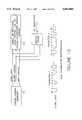
- FIG. 1is a schematic block diagram of the system of the present invention.
- FIG. 2is a schematic block diagram of a static copier interface and passive data tap on the copier control data cable for use with the present system.
- FIG. 3is a schematic block diagram of a dynamic copier interface and passive data tap on the copier control data cable fuse with the present system.
- FIG. 4is a schematic block diagram of a static copier interface and passive data tap located on the copier control computer.
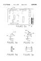
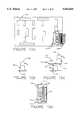
- FIG. 5Ais a schematic top plan view of the copier control computer board including control panel data cable connection.
- FIG. 5Bis a side plan view of the original control panel data cable connection.
- FIG. 5Cis a side plan view of the control panel data cable connection including a passive data tap for use with the present invention.
- FIG. 5Dis a side plan view of the Y-tap header used for parallel connection of the translator data cable with the control panel data cable.
- FIG. 5Eis a front plan view of the Y-tap header used for parallel connection of the translator data cable with the control panel data cable.
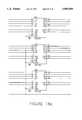
- FIG. 6a-bare a schematic diagram of multiplexed indicators and data tap scheme for use with the present system.
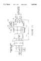
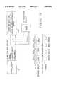
- FIG. 7is a schematic block diagram of a multiplexed data version translator for use with the present invention.
- FIG. 8is a schematic block diagram of a multiplexed data version translator with the random access memory, timer and universal asynchronous receiver/transmitter intergrated into the central processing unit.
- FIG. 9is a schematic block diagram of a static copier with an active data tap and buffer node computer.
- FIG. 10Ais a schematic top plan view of the copier control computer board including copier control panel data cable connection with active data tap.
- FIG. 10Bis a side plan view of the original control panel data cable connection.
- FIG. 10Cis a side plan view of the control panel data cable connection including an active data tap for use with the present invention.
- FIG. 10Dis a top plan view of the control panel data cable connection including an active data tap for use with the present invention.
- FIG. 11is a schematic block diagram of a multiplexed data version active data tap component of the translator.
- FIG. 12is a schematic block diagram of a buffer node computer component of the translator.
- FIG. 13is a schematic block diagram of a copier receiving power via the buffer node computer.
- FIG. 14is a schematic block diagram of a buffer node computer with a copier power switching capability.
- FIG. 15is a schematic block diagram of a serial data transmission technique from a copier control computer to the control panel display.
- FIG. 16is a schematic block diagram of a parallel data transmission technique from a copier control computer to the control panel display.
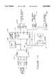
- FIG. 17is a schematic block diagram of a serial/parallel data version translator for use with the present invention.
- FIGS. 18a-dare a schematic diagram of a 12 ⁇ 48 FIFO memory for a parallel interface translator.
- FIGS. 19a-eare a schematic diagram of a copier multiplexed keyboard with remote keystroke monitoring and remote keystroke operation capabilities.
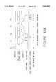
- FIG. 19fis a multiplexed keyboard timing diagram.
- FIG. 20a-bare an overview menu selection chart for use with the central computer.
- FIG. 20cis an expanded view of the information available from the COPIER menu selection.
- FIG. 20dis an expanded view of the information available from the SERVICE menu selection.
- FIG. 20eis an expanded view of the information available from the ADMIN menu selection.
- FIG. 20fis an expanded view of the information available from the SYSTEM menu selection.
- FIG. 21is a screen dump of the real-time monitoring mode for a Xerox 1025 copier.
- FIG. 22is a screen dump of the on-line help facility for fault codes.
- the present copier monitoring systemis capable of automatically monitoring, collecting and storing copier profiles, service records and diagnostics from a plurality of copier machines 2, located at various locations, from a central location or data collection point 4.
- a translator 6is used to provide a uniform interface between the copier and the central data collection point 4 for the copier status information.
- a translator 6is a microcomputer with specialized hardware and software that is customized to the particular copier and serves as an addressable node in the network.
- the translator 6is located at each copier site and communicates with the copier 2 through the use of a data tap (see FIGS. 2, 3 and 4) which monitors the status information transmitted from the copier control computer 10 to the copier status display 12 along a control panel data cable 18.
- the current copier status informationis stored in and transmitted by the translator 6 along a communication means, shown as line 52 to a data collection computer 16 at the central location 4 in response to a poll from a scanner/multiplexer 14 at the central location 4.
- a communication meansshown as line 52 to a data collection computer 16 at the central location 4 in response to a poll from a scanner/multiplexer 14 at the central location 4.
- the datais processed and stored in a database in the data collection computer 16.
- the present systemtherefore, links remote copiers to a central data collection point 4 through the use of, generally, a data tap 8 and translator 6 associated with the copier 2 on the customer premises and connected by communication means 52 to a scanner/multiplexer component 14 and status copier data collection component 16 at the central location 4.
- machine status monitoring in a copieris an output function, however, input functions such as operator key strokes from the control panel can be monitored.
- input functionssuch as operator key strokes from the control panel can be monitored.
- the output interfacescan generally be classified as “static” and “dynamic”. In addition to monitoring the output functions it is also desireable to provide remote input operation capabilities such that control panel keystrokes can be remotely generated.
- the static typeutilizes illuminating indicators, such as light emitting diodes ("LED's"), on a control panel 12 to indicate setup and operational status by either backlighting a transparency or as an indicator adjacent to a label.
- LED'slight emitting diodes
- the copier control computer 10directly controls the status indicators by turning them on or off as needed.
- fault conditions of the copierare indicated by error codes that can be, for example, displayed through the copy counter as a two digit code number.
- An example of this class of copieris the XEROX model 1025.
- the dynamic output typeutilizes not only illuminating indicators as before, but also some form of alphanumeric display device that can be altered to represent setup and status information in plain linguistic alphanumeric text.
- This display devicecould be a single or multiple line display utilizing technology such as a vacuum fluorescent, liquid crystal or light emitting diodes, or even CRT video displays.
- the copier control computer 10passes information over a control panel data cable 18 to the display device's controller which in turn converts the raw data into a formatted display image on the control panel 12. This information stream may be in either a serial or parallel manner.
- An example of this class of copieris the XEROX model 1040.
- the status indicatorsare usually time multiplexed to reduce power consumption and the overall number of connections between the copier control computer 10 and the control panel 12. This precludes simple monitoring of a voltage drop across a status device and requires the latching of the data at the time that a status device may be switched on.
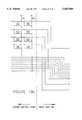
- FIG. 6a-bAn example, of a multiplexed display system can be seen in FIG. 6a-b. Twenty-four (24) LED's LED1-LED24, are organized into a three row by eight column matrix. As demonstrated in the multiplexer timing diagram, each row of eight LED's is selected through a common switching transistor, Q9-Q11 respectively, by applying a drive pulse to the base, terminal two of the device. The individual LED's within a common row are selected in parallel by applying a drive signal to the base of the column driver transistor Q1-Q8 respectively. In order to turn on LED10, it is necessary to apply drive signals to Q2 at the time Q10 is driven [C1 ⁇ ROW 1] at time T2. To capture the data column pattern for each row, it will be necessary that the CO-C7 and ROWO-ROW2 signals pass through from the data tap 8 to the translator 6 for processing.
- a data tap 8will be installed within the copier.
- the data tap 8will be placed in line with the control panel data cable 18 either on the copier control computer board 10 as shown in FIG. 4 or between the copier control computer 10 and the control panel 12 on the control panel data cable 18 as shown in FIGS. 2 and 3.
- the main purpose of the data tap 8is to provide a physical interface means to the translator 6 for a variety of copiers.
- the main purpose of the translator 6is to transform the various signals of the various copier machines 2 into uniform signals to be read by the data collection computer 16 as well as to demultiplex the copier status information that is scanned from the copier control computer 10 and return this data to the central data collection point 4 when it is polled to do so.
- the data tap 8is located inside of the copier 2 and must not violate any FCC regulation.
- the data tap 8in its simplest form is a passive device that merely passes the status information that passes from the copier control computer 10 to the control panel 12 to the translator 6, i.e., by a Y-tap header, Y-cable or buffer/driver device.
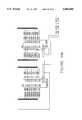
- the single CPU based translator system for a static multiplexed data interfaceis displayed in FIG. 7 and 8. It is microprocessor based using standard off-the-self components as well as basic design techniques.
- a 6809 microprocessor chipis the central processing unit 22 (CPU) along with a programmable address decoder 24 (16V8) used to select the support devices (i.e., RAM, ROM etc.) that are address mapped to the CPU 22.
- the stored program for the CPU 22can be found in the read only memory 26 (ROM, 27C64 or 27C256).
- the CPU stack information and temporary variablesare located in random access memory 28 (RAM, 6264).
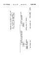
- the single CPU based translator 6is also comprised of nonvolatile random access memory 27 (NVRAM, MCM 2814), configuration selection switches 30, a digital port 32 (8255), analog to digital interfaces 34 (LM339), a timer 36 (555) and a universal asynchronous receiver/transmitter 38 (UART, 6850). If an 80C52 microcomprocessor chip is used as the central processing unit 22 the functions of the random access memory timer and the universal asynchronous receiver/transmitter are incorporated in the one chip as shown in FIG. 8.
- the NVRAM 27is read as with a conventional RAM but it retains the stored data if power is removed.
- This deviceis also known as an Electrically Erasable Programmable Read Only Memory (EEPROM) and/or a Battery Backed RAM (BBRAM) which contains its own on-board battery and change-over circuitry.
- Special information patterns, such as identifying signaturesare loaded into the NVRAM 27. This can be done at manufacturing time or remotely through the data collection computer 16. This information can then be used to remotely identify the copier within the network, e.g. as a header attached to the data returned to the central data collection point 4.
- the set of configuration selection switches 30enables the translator 6 to take on different functional characteristics based on the setting of the switches 30.
- the output of the switches 30are read by the CPU 22 through a digital port 32.
- This deviceconsists of three 8-bit parallel ports that are configured as to allow the CPU 22 to read in the digital level signals from the digital port 32.
- the state of the switches 30are read in at power-up time by the CPU 22 to set up certain operating characteristics of the translator 6.
- the CPU 22receives the status data from the digital port 32.
- the data that comes from the data tap 8 to the digital port 32is multiplexed data and the information may not be at appropriate signal levels for the digital port 32 or may contain undesirable signal noise and, therefore, must be conditioned to digital levels through an analog to digital interface 34.
- This interface 34consists of a voltage comparator 40 such as a LM339 or like component, which has two inputs, the signal to be conditioned from the copier 2 and a threshold reference voltage (VREF) see FIG. 7.
- the output of the comparator 40OV for a logical "0" state or +5V for a logical "1" state, will reflect the differential relation of the voltage input from the copier 2 and VREF. That is to say, if the input is greater than the reference the output will be OV and visa versa.
- the signalcan be read by the CPU 22 through the lines of the digital port 32. This information is then transferred to the RAM 28 for later evaluation, based on the characteristics from the configuration switches 30.
- the status information of the copierchanges at a relatively slow pace compared to the computational speed of a microprocessor based system. Therefore, it is only necessary for the translator 6 to periodically evaluate the condition of the copier 2. To accomplish this periodic acquisition technique, a method known as "interrupt driven" is used.
- a signal into the interrupt request (IRQ) input of the CPU 22, which causes the CPU 22 to execute an algorithm to input and store the data present from the eight row by eight column matrix,can be caused by a background timer 36 as shown in FIG. 7 that produces a signal at some interval or by a wire 25 as shown in FIG. 8 which connects the output port that represents ROW1 of the matrix of the analog to digital interface 34 to the IRQ of the CPU 22 which triggers the CPU 22 when data is present.
- the CPU 22is activated, the row LED is enabled and the column LEDs are stable, the data is stored and the next row of data is displayed. Later the CPU 22 can further evaluate the information to determine what status conditions exist.
- the algorithm for such a scanmight conceptually look as follows after the background timer 36 has pulsed the IRQ input or the output port that represents ROW1 of the matrix of the analog to digital interface 34 goes high (all signal references are from FIG. 6, multiplexer time diagram):
- the CPU 22polls the digital port input mapped to ROW1 and waits for it to be asserted at T1.
- the CPU 22now repeats steps 1 and 2, instead polling for ROW2 through ROW8 to be asserted at T2 through T8, respectively.
- the CPU 22then returns to its wait loop for the next timer interrupt.
- the CPU 22may also receive an interrupt request signal from the UART 38.
- the UART 38enables the CPU 22 to communicate with the scanner/multiplexer 14.
- the UART 38performs the task of converting the serial data that is transmitted from the scanner 14 into 8-bit bytes that the CPU 22 can process. It also converts the 8-bit bytes of data from the CPU 22 into a serial stream to be sent back to the scanner 14 along line 52.
- the transmit (TX) and receive (RX) signal linesare converted to/from standard RS-422 line drivers/receivers 50 for transmission of data over long distances with high immunity from external noise sources.
- Various transmission media, such as fiber optics, telephone lines, etc.,are also possible.
- the CPU 22executes an algorithm to retrieve the most recent condition evaluation in RAM 28.
- the reportcould be as simple as an encoded token that represents the meaning of the most recent evaluation. This token would then be decoded into the status text string by the scanner 14 or the user computer 16. Alternatively, the transmitted data could be the literal text string of the status message as it would be shown on the copier control panel 12.
- the "active" or “smart” data tap 3is located within the copier 2. It provides a physical interface to the copier 2 and has its own microcomputer to demultiplex the control panel information.
- the buffer node computer 5is located outside the copier 2 and is responsible for communication between the smart data tap 3 and the central data collection point 4. This division allows the smart data tap 3 to dedicate nearly all of its resources to monitoring the multiplexed data captured while the buffer node computer 5 can honor poll requests from the central data collection point 4. Only when a poll is received from the buffer node computer 5 does the smart data tap 3 discontinue its data monitoring operation and up-load its data to the buffer node computer 5 for return to the central data collection point 4. Together the smart data tap 3 and the buffer node computer 5 perform the same functions in the same manner as the single CPU translator 6.
- the smart data tap 3 shown in FIG. 11,is microprocessor based using standard off-the-shelf components as well as basic design techniques. Its components are similar to those described earlier in single CPU based translator design.
- the smart data tap 3is comprised of a central processing unit (CPU) 29 that may have a random access memory (RAM), universal asynchronous receiver/transmitter (UART) and a timer, either incorporated into the CPU29 or as separate components (not shown), as well as a programmable address decoder 24 (74LS138), read only memory 26 (ROM, 27C256), nonvolatile random access memory 27 (MCM2814), digital port 32 (74LS573), analog to digital voltage equalizer 34 (4504) and fiber optic transmitter and receiver connectors 11 and 13 (HFBR-1510 and HFBR-2501 respectively).
- CPUcentral processing unit
- RAMrandom access memory
- UARTuniversal asynchronous receiver/transmitter
- timereither incorporated into the CPU29 or as separate components (not shown)
- a programmable address decoder 2474LS138
- ROM, 27C256read only memory 26
- MCM2814nonvolatile random access memory 27
- digital port 3274LS573
- the smart data tap 3is installed directly onto the copier control computer board 10 as shown in FIGS. 10A and 10C.
- the control panel data cable 18is removed from its original position pinheader 19 of the copier control computer board 10, shown in FIG. 10B.
- the smart data tap 3In its place is inserted the smart data tap 3 by means of a mating header 15 that is part of the printed circuit board assembly.
- the rest of the smart tap microcomputer, shown in FIG. 10Dconsists of the actual computing elements packaged as surface mounted devices (SMD) 21, the front panel connector 19 and the fiber optic transmitter 11 and receiver 13 pair.
- SMDsurface mounted devices
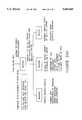
- the buffer node computer 5 as shown in FIG. 12is also microprocessor based using standard off the shelf components. It is comprised of a central processing unit 31 (CPU,80C52) that again may have random access memory (RAM), universal asynchronous receiver/transmitter (UART) and a timer either incorporated into the chip or as separate components (not shown). Also included in the buffer node computer 5 are a programmable address decoder 37 (74LS138), read only memory 39 (ROM,27C256), a universal asynchronous receiver/transmitter 33 (UART,8250), fiber optic transmit and receiver connectors 11 and 13 (HFBR-1510, HFBR-2501) and RS-422 line drivers/receivers 50 (3487,3486).
- CPUcentral processing unit
- UARTuniversal asynchronous receiver/transmitter
- the smart data tap 3 and buffer node computer 5 functionalityis basically the same as described earlier in said single CPU based translator.
- the smart data tap CPU 29continuously executes the stored instructions in ROM 26 to demultiplex the copier control information. This information is then stored in RAM until a poll is received from the buffer node computer 5.
- the buffer node computer 5sits idle waiting for a service request from the central data point 4.
- the CPU 31executes an algorithm to retrieve the copier status data from the smart data tap 3.
- the smart data tap CPU 29When the smart data tap CPU 29 receives the poll on its receive port an algorithm is executed to retrieve the copier status data from RAM.
- the UART located in the CPU 29converts the 8-bit bytes into serial data to be transmitted over the fiber optic cable 21.
- the datareaches the buffer node computer 5 the information is again converted back into 8 bit bytes by the UART 33.
- the UART 33sends an interrupt request signal along line 35 to the CPU 31 to activate an algorithm to retrieve the data, convert the data to serial format and then pass this data to the scanner 14 through the RS-422 line drivers/receivers 50.
- Control panel operator keysare often multiplexed using techniques, shown in FIG. 19a-e, that are similar to those employed with static display indicating devices as shown in FIGS. 6a-b.
- operator keyscan serve as both an status input means, showing the current status of any key(s) down, or as an output means that enables the system user to remotely "strike” a key(s) on the control panel.
- FIG. 19a-eThe process is shown in FIG. 19a-e.
- a keyboard S1-S32is shown organized as a 4 ⁇ 8 matrix.
- the rowsas strobed by signals ROW1* - ROW4* with the returning sense columns COL0-COL7 pulled to a logical 1 by resistors R1-R8, respectively.
- the resultant column datais read via the copier control to obtain D0-D7 through the buffer U1 for each occurrence of a row scan signal when the COL READ EN* signal is asserted.
- An example of this operationis found in the multiplexed timing diagram of FIG. 19f.
- a set of four 8-bit latches, U6-U9 corresponding to each matrix row,are provided to automatically capture the column sense signals.
- the sense column datais clocked into its respective latch.
- the translator CPU 22can read each row latch by asserting signals RD ROW 1 DATA* - RD ROW 4 DATA* asynchronous to the actual copier scanning operation to obtain a current image of the switch matrix. This image is then evaluated for copier specific information before being transmitted to the MAC computer 16.
- translator 6reads an $FF (hexadecimal) from the latch U8, between T4 and T5, to obtain the image of switches S17-S24. The image indicates that no keys are currently pressed within row 3.
- the translator 6In addition to reading the keyboard status, the translator 6 provides the system with the capability of remotely asserting the control panel keys exactly as if an operator were pressing the keys.
- a set of four 8-bit latches, U2-U5 corresponding to each matrix row,are connected together in parallel across the column sense lines COL0-COL7.
- the MAC computer 16transmits a code relating to a specific key over the communication line 52 to the desired translator 6.
- the translator 6decodes the command and writes the necessary data pattern into the selected latch.
- the row select lineis asserted that corresponds to the "programmed latch”
- the output drivers of the latchare enabled. This drives the column sense lines to the logic level corresponding to the pattern that was written into the latch.
- the datais then read back by the copier control computer via the column sense buffer U1.
- the keyboard status monitoring and driving control circuitryis part of the smart tap logic. This is necessary because the circuitry would have to be copier specific in design.
- the smart tap 3would receive commands from the MAC computer 16 via the buffer node computer 5, and would return status information in like manner.
- Another feature that can be added to the buffer node computer 5 outside of its communication functionis the ability to remotely power-down one or more of the network copiers 2 to prevent unauthorized use. This is accomplished by having the copier 2 receive power via the buffer node computer 5, placed in series between the copier 2 and wall outlet, instead of directly from a wall outlet as shown in FIG. 13. The buffer node computer 5 would receive power directly from a power cord 61, while switching the power line 63 to the copier or even an auditron to prevent unauthorized use.
- the probable switching technique, shown in FIG. 14would be to use a control line 65 from a digital port of the CPU 31 to drive the input of a solid state relay 67 (an optically isolated triac, such as a Cydrom D1D41).
- a copier enable/disable codewould be issued by the data collection computer 16 at a preset time if desired, to shut down the copier 2. Power could then be restored to the machine 2 the next morning in the same manner.
- serial transmissionWith serial transmission, shown in FIG. 15, information is passed from the copier control computer 10 to the display element 12a in a stream, bit-by-bit, at a specific data rate (bit rate).
- bit ratea specific data rate
- Each 8-bit byteis preceeded by a start bit, i.e., S1, and terminated by a stop bit, i.e., S2 to allow the receiving device to synchronize and recieve the incoming data.
- the receiving display element 12ahas some on-board intelligence (a dedicated function microcontroller) that processes the incoming data and formats it into the display output medium.
- This datacan either be control commands or ASCII (text) characters. If it is a command, the display element 12a of the control panel 12 will interpret what actions are to be taken (such as initializing the display, positioning the cursor at a specific line or address, etc.). If the data is text, the visual representation of the character will appear at the current location of the display cursor.
- the architecture for the translator 6 of the dynamic copier, shown in FIG. 17,is basically the same as for the static multiplexed data copier.
- the CPU 22, ROM 26, RAM 28, configuration switches 30 and UART1 38 functionsremain the same.
- UART22universal asynchronous receiver/transmitter
- FIFOfirst-in-first-out
- a two component version translator for the dynamic copieris also available (not shown).
- the buffer node computer 5will be the same. Minor changes to the active data tap will be necessary to compensate for the different copiers.
- the switches 30are connected to the digital port 32 inputs. At power-up time the CPU 22 reads the digital port 32 to determine the operating mode under which it should continue.
- the incoming serial data from the data tap 8first passes through a buffer 42A to condition the signal to levels that are appropriate for the UART2 38b.
- the UART2 38bis internally configured by the CPU 22 with the necessary parameters to receive the incoming data.
- the serial data streamis then converted to parallel data for use by the CPU 22.
- UART2 38binterrupts the CPU 22 to inform it that it has another byte of data for it. After the CPU 22 has read the data in, it would be stored in RAM 28 for later evaluation. Determining the end of the data stream may be by inference, for example, if no additional characters are detected after a predetermined amount of time or if an end of transmission character is found.
- the incoming parallel data from the data tap 8is 8-bit wide bytes (D0-D7 of FIG. 16).
- the parallel busalso has control signals (REGISTER SELECT and READ/WRITE) and an enable signal that is asserted when the data and control signals are valid. All of this data initially passes through a buffer 42B until the enable signal is asserted and then is automatically forwarded into a first-in-first-out (FIFO) memory 44.
- FIFOfirst-in-first-out
- the FIFO memory 44is constructed as shown in FIG. 18a-d. This particular memory arrangement is created from a composite of nine smaller 4 ⁇ 16 bit FIFO's (comprising 40105 devices) so connected in series/parallel as to form a wider and deeper 12 ⁇ 48 bit FIFO 44. These devices receive parallel input from the copier 2 into the data inputs (D0-D3) of devices U1, U4 and U7. The data is clocked into this first bank by the ENABLE* clock from the copier 2. From there the data ripples to the back of the FIFO 44 (U3, U6 and U9) in a "bucket brigade” fashion and is presented to the inputs of the digital port 32.
- the DATA RDY signalis sent by the 3-input AND gate (UllA) and is made available to the digital port 32.
- UllA3-input AND gate
- the CPU 22can poll the DATA RDY line to test for any data present in the FIFO 44.
- the CPU 22reads the digital port 32 to extract the data and then pulse the PB5 line of the digital port 32 to cause the next word of the FIFO 44 to propagate up.
- the CPU 22can also perform a master reset of the entire FIFO array by pulsing the FIFOCLR line, such as at T0.
- the FIFO 44fills with data as it is clocked in by ENABLE (T1, T2, T3 and T4) and is unloaded as it is clocked out by the CPU 22. Note that between T1 and T2 the FIFO memory 44 can absorb 48 words of data independently of the CPU 22 and can output the data to the CPU 22 independent of the copier 2. As with the serial interface method, the data is transferred to RAM 28 for buffering and evaluation.
- the data stream that is passed by a dynamic copier 2consists of discrete display commands and ASCII text characters.
- the translator 6strips the control characters and sends the ASCII text stream to the central computer 16 for evaluation and formatting.
- There are several other approaches to evaluating such a data streamFor example, sending the data directly to the central computer 16, unaltered, and letting the central computer 16 evaluate or reformat the data. Also, parsing the data looking for key words and making an inference that a problem exists from the key words can be achieved. Data can then be sent (by token or text stream) to the central computer 16 for evaluation or reformatting.
- the translators 6are polled by the scanner 14 to obtain the most recent status information.
- RS422 transmitter/receivers 5034866 that are wired to the scanner 14 at the central location 4.
- the communication means for transmitting the status information from the translator 6 to the scanner 14is not limited to hard wiring.
- the scanner 14is controlled by the data collection computer 16 and acts as a multiplex switcher which receives a message from the data collection computer 16 on which translator 6 to poll. The scanner 14 then makes cross connection to the appropriate translator 6 and passes the information to the data collection computer 16.
- the scanner/multiplexer 14can be any one of a number of such devices and are well known in the art.
- One exampleis a six port auto switch manufactured by L TEX ELECTRONICS under the name SMART 6.
- Possibilities for the polling of the translators 6include separate communication lines 52 for each translator 6, having the scanner 14 send a request to each unit in sequential round-robin fashion (shown in FIG. 1) or to daisy-chain the translators 6 together on a common line in a connected or unconnected ring wherein the scanner 14 would put the translator identifier of the unit being polled on the line 52.
- the overall remote monitoring of the networkis controlled by the data collection computer 16.
- the monitoringhas two modes, quasi-real-time or real-time. Quasi-real-time monitoring is the normal mode of operation when the data collection computer 16 is polling each individual copier 2 without giving priority to a specific location. For example, if there are 25 copiers being polled at the rate of one/second, then the entire sampling base is updated in 25 seconds. Therefore, the status of any given copier 2 in the network will be current to within the past twenty-five seconds.
- Real-time monitoringis accomplished in a special operating mode that causes the data collection computer 16 to focus in on a particular copier 2 and only poll the other copiers 2 as a background task and at a significantly lower rate. This allows the data collection computer 16 to sample the status of that particular copier 2 at a rate that will not appear to have any delay between the time an event occurs at the copier 2 and the time at which it is reported.
- the data collection computer 16can be an IBM compatible personal computer consisting of a monitor, keyboard, CPU, floppy drive, hard disk drive, and 640K of Random Access Memory running DOS 3.3.
- the data collection computer 16assembles the status information into various display formats. Some of the user features are displayed in the Menu Selection Tree (FIGS. 20a-20f). These features enable a database of information on copiers by manufacturer, model, options, location, facilities, etc. to be built. The database would then be merged with the status information to present a current representation of status of all copiers 2 on the monitoring network. Copiers 2 with operational problems are easily identified and service requests made and tracked in like manner.
- All of the stored informationcan also be utilized for a wide variety of report generation. It can also be used to predict potential or future machine failures. A rise in a certain type of fault could be detected and flagged as an upcoming failure. This type of window detection is similar to what the RIC system Xerox uses. However, the said system is a continuously on-line, real-time monitoring system. The present system could also alert a dispatch office automatically of pending or existing copier problems.
- the userWhen the data collection computer 16 is operating in the real-time mode the user is able to view an actual representation of the copier control panel 12 on the CRT screen of the data collection computer 16.
- FIG. 21is an actual screen dump of the monitoring mode for a Xerox 1025 copier.
- a screenBy having a copy of the control panel information, such a screen can be created and maintained for virtually any copier, whether or not the panel consists of a simple indicators (the static panel) or textual display characters (the dynamic panel). It then becomes a matter of processing the data against a map of the display layout of a given copier 2 to arrive at the end result.
- the screen of FIG. 22shows the current state of the ten major status indicators as well as the copier setup parameters, copy count and error codes, in the event of a copier fault.
- An error status signal sent from the copier controller computer 10 to the control panel 12is intercepted by the passive data tap 8, comprising a Y-tap 17.
- the datais transmitted to a translator 6 by means of a data translator cable 20.
- the translator 6has modular jacks which accept cooperating jacks on the translator data cable 20.
- the translator 6being polled for information then transmits data readable by the multiplexer/scanner 14 and stores certain data.
- the translator 6then transmits data to the scanner/multiplexer 14 at the central location along line 52 by the use of line drivers/receivers 50 (RS 422).
- line 52has modular jacks at each end which cooperate with jacks on both the translator and scanner/multiplexer 14.
- the scanner/multiplexer 14is controlled by a program in the data collection computer 16 under DOS 3.3. As such, the scanner/multiplexer 14 is integrated into the data collection computer 16.
- a user interfacecomprising a personal computer, including a CRT, keyboard and CPU, to extract other information, is used to alert the user to the location and status of an error.
Landscapes
- Engineering & Computer Science (AREA)
- Theoretical Computer Science (AREA)
- Physics & Mathematics (AREA)
- General Engineering & Computer Science (AREA)
- General Physics & Mathematics (AREA)
- Quality & Reliability (AREA)
- Computer Hardware Design (AREA)
- Computer Vision & Pattern Recognition (AREA)
- Microelectronics & Electronic Packaging (AREA)
- Control Or Security For Electrophotography (AREA)
Abstract
Description
Claims (6)
Priority Applications (4)
| Application Number | Priority Date | Filing Date | Title |
|---|---|---|---|
| US08/478,357US5603060A (en) | 1989-12-13 | 1995-06-07 | Method of controlling copy machines from a remote location |
| US08/724,640US6009284A (en) | 1989-12-13 | 1996-10-01 | System and method for controlling image processing devices from a remote location |
| US09/421,992US6282383B1 (en) | 1989-12-13 | 1999-10-19 | Method of monitoring and initiating operational commands in an image processing device |
| US09/902,066US7417753B2 (en) | 1989-12-13 | 2001-07-10 | System for automatically monitoring copiers from a remote location |
Applications Claiming Priority (5)
| Application Number | Priority Date | Filing Date | Title |
|---|---|---|---|
| US07/450,605US5084875A (en) | 1989-12-13 | 1989-12-13 | System for automatically monitoring copiers from a remote location |
| US07/567,388US5214772A (en) | 1989-12-13 | 1990-08-14 | System for automatically monitoring copiers from a remote location |
| US07/978,278US5333286A (en) | 1989-12-13 | 1992-11-18 | Two way copier monitoring system |
| US24759194A | 1994-05-23 | 1994-05-23 | |
| US08/478,357US5603060A (en) | 1989-12-13 | 1995-06-07 | Method of controlling copy machines from a remote location |
Related Parent Applications (1)
| Application Number | Title | Priority Date | Filing Date |
|---|---|---|---|
| US24759194AContinuation | 1989-12-13 | 1994-05-23 |
Related Child Applications (1)
| Application Number | Title | Priority Date | Filing Date |
|---|---|---|---|
| US08/724,640ContinuationUS6009284A (en) | 1989-12-13 | 1996-10-01 | System and method for controlling image processing devices from a remote location |
Publications (1)
| Publication Number | Publication Date |
|---|---|
| US5603060Atrue US5603060A (en) | 1997-02-11 |
Family
ID=27036063
Family Applications (2)
| Application Number | Title | Priority Date | Filing Date |
|---|---|---|---|
| US07/978,278Expired - LifetimeUS5333286A (en) | 1989-12-13 | 1992-11-18 | Two way copier monitoring system |
| US08/478,357Expired - LifetimeUS5603060A (en) | 1989-12-13 | 1995-06-07 | Method of controlling copy machines from a remote location |
Family Applications Before (1)
| Application Number | Title | Priority Date | Filing Date |
|---|---|---|---|
| US07/978,278Expired - LifetimeUS5333286A (en) | 1989-12-13 | 1992-11-18 | Two way copier monitoring system |
Country Status (1)
| Country | Link |
|---|---|
| US (2) | US5333286A (en) |
Cited By (41)
| Publication number | Priority date | Publication date | Assignee | Title |
|---|---|---|---|---|
| US5798738A (en)* | 1995-03-25 | 1998-08-25 | Ricoh Company, Ltd. | Printing manager system for a copier in a network |
| US5852746A (en)* | 1995-06-26 | 1998-12-22 | Canon Kabushiki Kaisha | System for transmitting a message using status button to system administrator by using a signal comprising predetermined number of changes effected over a period |
| US5884096A (en)* | 1995-08-25 | 1999-03-16 | Apex Pc Solutions, Inc. | Interconnection system for viewing and controlling remotely connected computers with on-screen video overlay for controlling of the interconnection switch |
| US5923866A (en)* | 1996-04-26 | 1999-07-13 | Acer Incorporated | Method and apparatus for realizing a keyboard key function on a remote control |
| US6003078A (en)* | 1996-11-15 | 1999-12-14 | Canon Information Systems, Inc. | Automatic service requests over the world wide web |
| US6009284A (en)* | 1989-12-13 | 1999-12-28 | The Weinberger Group, L.L.C. | System and method for controlling image processing devices from a remote location |
| US6025925A (en)* | 1995-06-23 | 2000-02-15 | Lexmark International, Inc. | Method and apparatus for providing job accounting information to a host computer from a printer |
| US6304895B1 (en) | 1997-08-22 | 2001-10-16 | Apex Inc. | Method and system for intelligently controlling a remotely located computer |
| US20020091850A1 (en)* | 1992-10-23 | 2002-07-11 | Cybex Corporation | System and method for remote monitoring and operation of personal computers |
| US20020116550A1 (en)* | 2000-09-22 | 2002-08-22 | Hansen James R. | Retrieving data from a server |
| US20020146256A1 (en)* | 2001-03-06 | 2002-10-10 | Nobuo Sekiguchi | Image forming apparatus and method of controlling the same |
| US6498611B1 (en) | 2000-01-28 | 2002-12-24 | Lexmark International, Inc. | System and method for providing a virtual operator panel for a peripheral device |
| US6516952B1 (en)* | 1999-05-13 | 2003-02-11 | 3Com Corporation | Dual mode serializer-deserializer for data networks |
| US20030227643A1 (en)* | 2002-03-06 | 2003-12-11 | Pharos Systems International, Inc. | Document processing system including multi-device compatible interface and related methods |
| US20040255263A1 (en)* | 2003-03-25 | 2004-12-16 | Mitsuo Ando | Image forming apparatus and method for operating image forming apparatus by using remote application |
| US20050021772A1 (en)* | 2003-02-21 | 2005-01-27 | Felix Shedrinsky | Establishing a virtual tunnel between two computer programs |
| US20050063108A1 (en)* | 2003-09-24 | 2005-03-24 | Belkin Corporation | Distance extender and method making use of same |
| US7016058B1 (en)* | 1996-01-18 | 2006-03-21 | Ricoh Company, Ltd. | Network control method and system |
| US7117239B1 (en) | 2000-07-28 | 2006-10-03 | Axeda Corporation | Reporting the state of an apparatus to a remote computer |
| US7149792B1 (en) | 2000-11-20 | 2006-12-12 | Axeda Corporation | Device registration mechanism |
| US20070033265A1 (en)* | 1998-09-22 | 2007-02-08 | Avocent Huntsville Corporation | System and method for accessing and operating personal computers remotely |
| US7185014B1 (en) | 2000-09-22 | 2007-02-27 | Axeda Corporation | Retrieving data from a server |
| US20070150903A1 (en)* | 2002-04-17 | 2007-06-28 | Axeda Corporation | XML Scripting of SOAP Commands |
| US20070291004A1 (en)* | 1999-08-25 | 2007-12-20 | Avocent Redmond Corporation | KVM switch including a terminal emulator |
| US20080154957A1 (en)* | 2006-12-26 | 2008-06-26 | Questra Corporation | Managing configurations of distributed devices |
| US20080309965A1 (en)* | 2007-06-14 | 2008-12-18 | Dex Imaging | Apparatus and method for discovering printers within an enterprise |
| US7496666B2 (en) | 1997-10-28 | 2009-02-24 | Raritan Americas, Inc. | Multi-user computer system |
| US20100189219A1 (en)* | 2009-01-29 | 2010-07-29 | Searete Llc, A Limited Liability Corporation Of The State Of Delaware | Diagnostic delivery service |
| US7768662B2 (en) | 2002-02-12 | 2010-08-03 | Xerox Corporation | System and method for controlling access |
| US7769619B1 (en) | 2000-08-14 | 2010-08-03 | Imaging Portals, Inc. | Automated business machine management |
| US7962111B2 (en) | 2002-02-25 | 2011-06-14 | ADC Wireless, Inc. | Distributed automatic gain control system |
| US8009173B2 (en) | 2006-08-10 | 2011-08-30 | Avocent Huntsville Corporation | Rack interface pod with intelligent platform control |
| US20110228332A1 (en)* | 2010-03-18 | 2011-09-22 | Emerge Print Management, Llc | Patrol Device Field Installation Notification Method and System |
| US20110228314A1 (en)* | 2010-03-18 | 2011-09-22 | Dex Imaging, Inc. | Field Metering Patrol System and Method for Metering and Monitoring Printers |
| US8260896B2 (en) | 2007-02-02 | 2012-09-04 | Mwa Intelligence, Inc. | Monitoring business machines using a mesh network on field nodes |
| US8370479B2 (en) | 2006-10-03 | 2013-02-05 | Axeda Acquisition Corporation | System and method for dynamically grouping devices based on present device conditions |
| US8406119B2 (en) | 2001-12-20 | 2013-03-26 | Axeda Acquisition Corporation | Adaptive device-initiated polling |
| US8427489B2 (en) | 2006-08-10 | 2013-04-23 | Avocent Huntsville Corporation | Rack interface pod with intelligent platform control |
| US8478861B2 (en) | 2007-07-06 | 2013-07-02 | Axeda Acquisition Corp. | Managing distributed devices with limited connectivity |
| US9577922B2 (en) | 2014-02-18 | 2017-02-21 | Commscope Technologies Llc | Selectively combining uplink signals in distributed antenna systems |
| US9573807B1 (en) | 2010-10-13 | 2017-02-21 | Distribution Management, Inc. | Managed print service automated and integrated system |
Families Citing this family (35)
| Publication number | Priority date | Publication date | Assignee | Title |
|---|---|---|---|---|
| US5819110A (en)* | 1995-06-05 | 1998-10-06 | Ricoh Company, Ltd. | System for determining whether connection or connectionless modes of communication should be used to transmit information between devices in accordance with priorities of events |
| US5333286A (en)* | 1989-12-13 | 1994-07-26 | Joseph Weinberger | Two way copier monitoring system |
| CA2075774C (en)* | 1991-08-27 | 2000-10-17 | Jeff D. Pipkins | Bidirectional parallel protocol |
| JP3227750B2 (en)* | 1991-12-10 | 2001-11-12 | ミノルタ株式会社 | Copier |
| JP3660363B2 (en)* | 1992-05-28 | 2005-06-15 | 株式会社リコー | Image forming apparatus management system and image forming apparatus |
| JP3339921B2 (en)* | 1992-11-30 | 2002-10-28 | 株式会社リコー | Communication control device for image forming device management system |
| US5398257A (en)* | 1993-01-11 | 1995-03-14 | Groenteman; Frank S. | Copier and monitoring network |
| EP0652523B1 (en)* | 1993-11-10 | 1999-06-02 | Nec Corporation | Remote monitoring system |
| JPH07147615A (en)* | 1993-11-22 | 1995-06-06 | Canon Inc | Image processing device |
| US5550957A (en)* | 1994-12-07 | 1996-08-27 | Lexmark International, Inc. | Multiple virtual printer network interface |
| US5640495A (en)* | 1994-12-20 | 1997-06-17 | Lexmark International, Inc. | Computer-printer interface control for bidirectional/undirectional data communications |
| US5636333A (en)* | 1994-12-20 | 1997-06-03 | Lexmark International, Inc. | Multi-protocol network interface |
| JP3442174B2 (en)* | 1995-01-19 | 2003-09-02 | 株式会社リコー | Image forming device service system |
| CN100381941C (en)* | 1995-02-22 | 2008-04-16 | 佳能株式会社 | Image forming apparatus, apparatus for supplying image data to image forming apparatus, and method of interfacing two apparatuses |
| US5699494A (en)* | 1995-02-24 | 1997-12-16 | Lexmark International, Inc. | Remote replication of printer operator panel |
| US5727135A (en)* | 1995-03-23 | 1998-03-10 | Lexmark International, Inc. | Multiple printer status information indication |
| US5905906A (en)* | 1995-03-31 | 1999-05-18 | Lexmark International, Inc. | Method and apparatus for configuring multiple printers on a network |
| US5787149A (en)* | 1995-11-16 | 1998-07-28 | Equitrac Corporation | Method and apparatus for managing remotely located document producing machines by using cellular radios |
| US5720015A (en)* | 1996-04-22 | 1998-02-17 | Lexmark International, Inc. | Method and apparatus for providing remote printer resource management |
| US5873659A (en)* | 1996-04-24 | 1999-02-23 | Edwards; Steve Michael | Method and apparatus for providing a printer having internal queue job management |
| US5819071A (en)* | 1996-05-01 | 1998-10-06 | Jet Propulsion Laboratory | Remote simulation of data transmission |
| US6246485B1 (en) | 1996-05-23 | 2001-06-12 | Lexmark International, Inc. | Printer communication system and method |
| US6108492A (en)* | 1997-02-14 | 2000-08-22 | Toshiba America Information Systems | Remote monitoring system |
| US6775264B1 (en)* | 1997-03-03 | 2004-08-10 | Webley Systems, Inc. | Computer, internet and telecommunications based network |
| JP3065053B2 (en) | 1998-01-06 | 2000-07-12 | セイコーエプソン株式会社 | Device monitoring system, local monitoring device, integrated monitoring device, device monitoring method, and computer-readable medium storing program |
| US6707567B1 (en) | 1998-05-20 | 2004-03-16 | Ricoh Company, Ltd. | Supervising system for image forming apparatus and method thereof |
| US6832250B1 (en) | 1999-04-13 | 2004-12-14 | Lexmark International, Inc. | Usage-based billing and management system and method for printers and other assets |
| US6353869B1 (en)* | 1999-05-14 | 2002-03-05 | Emc Corporation | Adaptive delay of polling frequencies in a distributed system with a queued lock |
| US6192202B1 (en)* | 2000-02-16 | 2001-02-20 | Toshiba Tec Kabushiki Kaisha | Image forming system using plural copying apparatus to perform one copy job |
| US7711533B2 (en)* | 2000-12-12 | 2010-05-04 | Uri Wilensky | Distributed agent network using object based parallel modeling language to dynamically model agent activities |
| US8418065B2 (en)* | 2001-07-16 | 2013-04-09 | Nuance Communications, Inc. | Method of and system for dynamically controlling during run time a multifunction peripheral (MFP) touch panel user interface (UI) from an external remote network-connected computer |
| US7020702B2 (en)* | 2001-09-20 | 2006-03-28 | Lexmark International, Inc. | Method and apparatus to obtain real-time status information from a networked device |
| GB2424290A (en)* | 2005-03-10 | 2006-09-20 | Nrg Man Ltd | Managing printing devices at distributed sites |
| US8319993B2 (en)* | 2008-01-24 | 2012-11-27 | Sharp Laboratories Of America, Inc. | Methods for operating user interfaces of a device controllable at a plurality of access points |
| JP5598079B2 (en)* | 2010-05-14 | 2014-10-01 | セイコーエプソン株式会社 | Recording system and recording system control method |
Citations (32)
| Publication number | Priority date | Publication date | Assignee | Title |
|---|---|---|---|---|
| US3400328A (en)* | 1964-02-24 | 1968-09-03 | Texas Instruments Inc | Anisotropic ferromagnetic thin film magnetometer systems utilizing a modulator to perturb the field on the sensitive axis |
| US3623013A (en)* | 1969-08-13 | 1971-11-23 | Burroughs Corp | Data processing network and improved terminal |
| US3744043A (en)* | 1971-06-01 | 1973-07-03 | Westinghouse Electric Corp | Environmental data system |
| US3916177A (en)* | 1973-12-10 | 1975-10-28 | Honeywell Inf Systems | Remote entry diagnostic and verification procedure apparatus for a data processing unit |
| US4144550A (en)* | 1977-08-30 | 1979-03-13 | Xerox Corporation | Reproduction machine using fiber optics communication system |
| US4162488A (en)* | 1977-03-11 | 1979-07-24 | Emergency Products Corporation | Alarm system |
| US4183089A (en)* | 1977-08-30 | 1980-01-08 | Xerox Corporation | Data communications system for a reproduction machine having a master and secondary controllers |
| US4213694A (en)* | 1977-05-31 | 1980-07-22 | International Business Machines Corporation | Copy production machines |
| US4311986A (en)* | 1978-09-13 | 1982-01-19 | The Bendix Corporation | Single line multiplexing system for sensors and actuators |
| US4330847A (en)* | 1976-10-04 | 1982-05-18 | International Business Machines Corporation | Store and forward type of text processing unit |
| US4412292A (en)* | 1981-02-17 | 1983-10-25 | The Coca-Cola Company | System for the remote monitoring of vending machines |
| US4463418A (en)* | 1981-06-30 | 1984-07-31 | International Business Machines Corporation | Error correction from remote data processor by communication and reconstruction of processor status storage disk |
| US4497037A (en)* | 1980-11-26 | 1985-01-29 | Nippondenso Co., Ltd. | Apparatus for managing a group of copying machines |
| US4545013A (en)* | 1979-01-29 | 1985-10-01 | Infinet Inc. | Enhanced communications network testing and control system |
| US4583834A (en)* | 1977-09-16 | 1986-04-22 | Ricoh Company, Ltd. | Copying apparatus |
| US4623244A (en)* | 1976-10-04 | 1986-11-18 | International Business Machines Corporation | Copy production machines |
| US4633412A (en)* | 1984-04-26 | 1986-12-30 | At&T Bell Laboratories | Option protocol arrangement for stored program rectifier controller |
| US4652698A (en)* | 1984-08-13 | 1987-03-24 | Ncr Corporation | Method and system for providing system security in a remote terminal environment |
| US4695946A (en)* | 1984-10-25 | 1987-09-22 | Unisys Corporation | Maintenance subsystem for computer network including power control and remote diagnostic center |
| US4712213A (en)* | 1985-12-11 | 1987-12-08 | Northern Telecom Limited | Flip status line |
| US4745602A (en)* | 1985-09-20 | 1988-05-17 | Minolta Camera Company, Ltd. | Printer error and control system |
| US4870644A (en)* | 1982-09-21 | 1989-09-26 | Xerox Corporation | Control crash diagnostic strategy and RAM display |
| US4947397A (en)* | 1988-11-02 | 1990-08-07 | Xerox Corporation | Job scheduler diagnostics |
| US4962368A (en)* | 1989-05-04 | 1990-10-09 | General Signal Corporation | Reliability and workability test apparatus for an environmental monitoring system |
| US4964065A (en)* | 1987-03-12 | 1990-10-16 | Decibel Products, Inc. | Computer-controlled electronic system monitor |
| US5016059A (en)* | 1989-02-28 | 1991-05-14 | Wilfred Smeiman | Photocopy machine remotely controlled copy counting system |
| US5038319A (en)* | 1989-04-24 | 1991-08-06 | Xerox Corporation | System for recording and remotely accessing operating data in a reproduction machine |
| US5057866A (en)* | 1990-05-04 | 1991-10-15 | Xerox Corporation | Remotely accessible copier calculator |
| US5077582A (en)* | 1988-05-17 | 1991-12-31 | Monitel Products Corp. | Photocopy monitoring system |
| US5084875A (en)* | 1989-12-13 | 1992-01-28 | Joseph Weinberger | System for automatically monitoring copiers from a remote location |
| US5214772A (en)* | 1989-12-13 | 1993-05-25 | Joseph Weinberger | System for automatically monitoring copiers from a remote location |
| US5333286A (en)* | 1989-12-13 | 1994-07-26 | Joseph Weinberger | Two way copier monitoring system |
Family Cites Families (2)
| Publication number | Priority date | Publication date | Assignee | Title |
|---|---|---|---|---|
| US3400378A (en)* | 1965-10-22 | 1968-09-03 | Motorola Inc | Data acquisition system with plural scanners at plural remote stations |
| JPS6081656A (en)* | 1983-10-11 | 1985-05-09 | Canon Inc | address translation device |
- 1992
- 1992-11-18USUS07/978,278patent/US5333286A/ennot_activeExpired - Lifetime
- 1995
- 1995-06-07USUS08/478,357patent/US5603060A/ennot_activeExpired - Lifetime
Patent Citations (32)
| Publication number | Priority date | Publication date | Assignee | Title |
|---|---|---|---|---|
| US3400328A (en)* | 1964-02-24 | 1968-09-03 | Texas Instruments Inc | Anisotropic ferromagnetic thin film magnetometer systems utilizing a modulator to perturb the field on the sensitive axis |
| US3623013A (en)* | 1969-08-13 | 1971-11-23 | Burroughs Corp | Data processing network and improved terminal |
| US3744043A (en)* | 1971-06-01 | 1973-07-03 | Westinghouse Electric Corp | Environmental data system |
| US3916177A (en)* | 1973-12-10 | 1975-10-28 | Honeywell Inf Systems | Remote entry diagnostic and verification procedure apparatus for a data processing unit |
| US4330847A (en)* | 1976-10-04 | 1982-05-18 | International Business Machines Corporation | Store and forward type of text processing unit |
| US4623244A (en)* | 1976-10-04 | 1986-11-18 | International Business Machines Corporation | Copy production machines |
| US4162488A (en)* | 1977-03-11 | 1979-07-24 | Emergency Products Corporation | Alarm system |
| US4213694A (en)* | 1977-05-31 | 1980-07-22 | International Business Machines Corporation | Copy production machines |
| US4144550A (en)* | 1977-08-30 | 1979-03-13 | Xerox Corporation | Reproduction machine using fiber optics communication system |
| US4183089A (en)* | 1977-08-30 | 1980-01-08 | Xerox Corporation | Data communications system for a reproduction machine having a master and secondary controllers |
| US4583834A (en)* | 1977-09-16 | 1986-04-22 | Ricoh Company, Ltd. | Copying apparatus |
| US4311986A (en)* | 1978-09-13 | 1982-01-19 | The Bendix Corporation | Single line multiplexing system for sensors and actuators |
| US4545013A (en)* | 1979-01-29 | 1985-10-01 | Infinet Inc. | Enhanced communications network testing and control system |
| US4497037A (en)* | 1980-11-26 | 1985-01-29 | Nippondenso Co., Ltd. | Apparatus for managing a group of copying machines |
| US4412292A (en)* | 1981-02-17 | 1983-10-25 | The Coca-Cola Company | System for the remote monitoring of vending machines |
| US4463418A (en)* | 1981-06-30 | 1984-07-31 | International Business Machines Corporation | Error correction from remote data processor by communication and reconstruction of processor status storage disk |
| US4870644A (en)* | 1982-09-21 | 1989-09-26 | Xerox Corporation | Control crash diagnostic strategy and RAM display |
| US4633412A (en)* | 1984-04-26 | 1986-12-30 | At&T Bell Laboratories | Option protocol arrangement for stored program rectifier controller |
| US4652698A (en)* | 1984-08-13 | 1987-03-24 | Ncr Corporation | Method and system for providing system security in a remote terminal environment |
| US4695946A (en)* | 1984-10-25 | 1987-09-22 | Unisys Corporation | Maintenance subsystem for computer network including power control and remote diagnostic center |
| US4745602A (en)* | 1985-09-20 | 1988-05-17 | Minolta Camera Company, Ltd. | Printer error and control system |
| US4712213A (en)* | 1985-12-11 | 1987-12-08 | Northern Telecom Limited | Flip status line |
| US4964065A (en)* | 1987-03-12 | 1990-10-16 | Decibel Products, Inc. | Computer-controlled electronic system monitor |
| US5077582A (en)* | 1988-05-17 | 1991-12-31 | Monitel Products Corp. | Photocopy monitoring system |
| US4947397A (en)* | 1988-11-02 | 1990-08-07 | Xerox Corporation | Job scheduler diagnostics |
| US5016059A (en)* | 1989-02-28 | 1991-05-14 | Wilfred Smeiman | Photocopy machine remotely controlled copy counting system |
| US5038319A (en)* | 1989-04-24 | 1991-08-06 | Xerox Corporation | System for recording and remotely accessing operating data in a reproduction machine |
| US4962368A (en)* | 1989-05-04 | 1990-10-09 | General Signal Corporation | Reliability and workability test apparatus for an environmental monitoring system |
| US5084875A (en)* | 1989-12-13 | 1992-01-28 | Joseph Weinberger | System for automatically monitoring copiers from a remote location |
| US5214772A (en)* | 1989-12-13 | 1993-05-25 | Joseph Weinberger | System for automatically monitoring copiers from a remote location |
| US5333286A (en)* | 1989-12-13 | 1994-07-26 | Joseph Weinberger | Two way copier monitoring system |
| US5057866A (en)* | 1990-05-04 | 1991-10-15 | Xerox Corporation | Remotely accessible copier calculator |
Non-Patent Citations (5)
| Title |
|---|
| Hyde, B. D., et al., "Copier Power Control System," IBM Technical Disclosure Bulletin, vol. 25, No. 2, Jul. 1982, New York, USA, pp. 521-522. |
| Hyde, B. D., et al., Copier Power Control System, IBM Technical Disclosure Bulletin, vol. 25, No. 2, Jul. 1982, New York, USA, pp. 521 522.* |
| Kodak Teleassistance Network, Copyright, Eastman Kodak Company, 1986.* |
| Rochester Democrat and Chronicle, by David Lindley, Mar. 28, 1990.* |
| Xerox 1090 Copier Electronic Data Interface Operator Guide and Installation, Nov. 1988.* |
Cited By (85)
| Publication number | Priority date | Publication date | Assignee | Title |
|---|---|---|---|---|
| US7417753B2 (en) | 1989-12-13 | 2008-08-26 | Imaging Portals, Inc. | System for automatically monitoring copiers from a remote location |
| US6009284A (en)* | 1989-12-13 | 1999-12-28 | The Weinberger Group, L.L.C. | System and method for controlling image processing devices from a remote location |
| US6282383B1 (en) | 1989-12-13 | 2001-08-28 | The Weinberger Group, L.L.C. | Method of monitoring and initiating operational commands in an image processing device |
| US20050200882A9 (en)* | 1989-12-13 | 2005-09-15 | Joseph Weinberger | System for automatically monitoring copiers from a remote location |
| US20020048462A1 (en)* | 1989-12-13 | 2002-04-25 | Joseph Weinberger | System for automatically monitoring copiers from a remote location |
| USRE44814E1 (en) | 1992-10-23 | 2014-03-18 | Avocent Huntsville Corporation | System and method for remote monitoring and operation of personal computers |
| US20020091850A1 (en)* | 1992-10-23 | 2002-07-11 | Cybex Corporation | System and method for remote monitoring and operation of personal computers |
| US5798738A (en)* | 1995-03-25 | 1998-08-25 | Ricoh Company, Ltd. | Printing manager system for a copier in a network |
| US6025925A (en)* | 1995-06-23 | 2000-02-15 | Lexmark International, Inc. | Method and apparatus for providing job accounting information to a host computer from a printer |
| US5852746A (en)* | 1995-06-26 | 1998-12-22 | Canon Kabushiki Kaisha | System for transmitting a message using status button to system administrator by using a signal comprising predetermined number of changes effected over a period |
| US5884096A (en)* | 1995-08-25 | 1999-03-16 | Apex Pc Solutions, Inc. | Interconnection system for viewing and controlling remotely connected computers with on-screen video overlay for controlling of the interconnection switch |
| US7016058B1 (en)* | 1996-01-18 | 2006-03-21 | Ricoh Company, Ltd. | Network control method and system |
| US6106564A (en)* | 1996-04-26 | 2000-08-22 | Acer Incorporated | Method and apparatus for realizing a keyboard key function on a remote control |
| US5923866A (en)* | 1996-04-26 | 1999-07-13 | Acer Incorporated | Method and apparatus for realizing a keyboard key function on a remote control |
| US6003078A (en)* | 1996-11-15 | 1999-12-14 | Canon Information Systems, Inc. | Automatic service requests over the world wide web |
| US6304895B1 (en) | 1997-08-22 | 2001-10-16 | Apex Inc. | Method and system for intelligently controlling a remotely located computer |
| US7496666B2 (en) | 1997-10-28 | 2009-02-24 | Raritan Americas, Inc. | Multi-user computer system |
| US7747702B2 (en) | 1998-09-22 | 2010-06-29 | Avocent Huntsville Corporation | System and method for accessing and operating personal computers remotely |
| US20070033265A1 (en)* | 1998-09-22 | 2007-02-08 | Avocent Huntsville Corporation | System and method for accessing and operating personal computers remotely |
| US6516952B1 (en)* | 1999-05-13 | 2003-02-11 | 3Com Corporation | Dual mode serializer-deserializer for data networks |
| US20070291004A1 (en)* | 1999-08-25 | 2007-12-20 | Avocent Redmond Corporation | KVM switch including a terminal emulator |
| US8269783B2 (en) | 1999-08-25 | 2012-09-18 | Avocent Redmond Corporation | KVM switch including a terminal emulator |
| US20080082705A1 (en)* | 1999-08-25 | 2008-04-03 | Avocent Redmond Corporation | KVM switch including a terminal emulator |
| US6498611B1 (en) | 2000-01-28 | 2002-12-24 | Lexmark International, Inc. | System and method for providing a virtual operator panel for a peripheral device |
| US8055758B2 (en) | 2000-07-28 | 2011-11-08 | Axeda Corporation | Reporting the state of an apparatus to a remote computer |
| US20070011295A1 (en)* | 2000-07-28 | 2007-01-11 | Axeda Corporation, A Massachusetts Corporation | Reporting the state of an apparatus to a remote computer |
| US7117239B1 (en) | 2000-07-28 | 2006-10-03 | Axeda Corporation | Reporting the state of an apparatus to a remote computer |
| US8898294B2 (en) | 2000-07-28 | 2014-11-25 | Axeda Corporation | Reporting the state of an apparatus to a remote computer |
| US7769619B1 (en) | 2000-08-14 | 2010-08-03 | Imaging Portals, Inc. | Automated business machine management |
| US20070198661A1 (en)* | 2000-09-22 | 2007-08-23 | Axeda Corporation | Retrieving data from a server |
| US10069937B2 (en) | 2000-09-22 | 2018-09-04 | Ptc Inc. | Retrieving data from a server |
| US7185014B1 (en) | 2000-09-22 | 2007-02-27 | Axeda Corporation | Retrieving data from a server |
| US8762497B2 (en) | 2000-09-22 | 2014-06-24 | Axeda Corporation | Retrieving data from a server |
| US20020116550A1 (en)* | 2000-09-22 | 2002-08-22 | Hansen James R. | Retrieving data from a server |
| US7937370B2 (en) | 2000-09-22 | 2011-05-03 | Axeda Corporation | Retrieving data from a server |
| US8108543B2 (en) | 2000-09-22 | 2012-01-31 | Axeda Corporation | Retrieving data from a server |
| US7149792B1 (en) | 2000-11-20 | 2006-12-12 | Axeda Corporation | Device registration mechanism |
| US20020146256A1 (en)* | 2001-03-06 | 2002-10-10 | Nobuo Sekiguchi | Image forming apparatus and method of controlling the same |
| US6782218B2 (en)* | 2001-03-06 | 2004-08-24 | Canon Kabushiki Kaisha | Image forming apparatus having control section for enabling/disabling tabbed sheet print mode setting section, and corresponding method and storage medium thereof |
| US9097555B2 (en) | 2001-08-14 | 2015-08-04 | Mwa Intelligence, Inc. | Monitoring device mesh network systems and methods |
| US9674067B2 (en) | 2001-12-20 | 2017-06-06 | PTC, Inc. | Adaptive device-initiated polling |
| US9170902B2 (en) | 2001-12-20 | 2015-10-27 | Ptc Inc. | Adaptive device-initiated polling |
| US8406119B2 (en) | 2001-12-20 | 2013-03-26 | Axeda Acquisition Corporation | Adaptive device-initiated polling |
| US7768662B2 (en) | 2002-02-12 | 2010-08-03 | Xerox Corporation | System and method for controlling access |
| US7962111B2 (en) | 2002-02-25 | 2011-06-14 | ADC Wireless, Inc. | Distributed automatic gain control system |
| US20030227643A1 (en)* | 2002-03-06 | 2003-12-11 | Pharos Systems International, Inc. | Document processing system including multi-device compatible interface and related methods |
| US7366799B2 (en) | 2002-03-06 | 2008-04-29 | Pharos Systems International, Inc. | Document processing system including multi-device compatible interface and related methods |
| US9591065B2 (en) | 2002-04-17 | 2017-03-07 | Ptc Inc. | Scripting of SOAP commands |
| US10708346B2 (en) | 2002-04-17 | 2020-07-07 | Ptc Inc. | Scripting of soap commands |
| US8060886B2 (en) | 2002-04-17 | 2011-11-15 | Axeda Corporation | XML scripting of SOAP commands |
| US20070150903A1 (en)* | 2002-04-17 | 2007-06-28 | Axeda Corporation | XML Scripting of SOAP Commands |
| US8752074B2 (en) | 2002-04-17 | 2014-06-10 | Axeda Corporation | Scripting of soap commands |
| US10069939B2 (en) | 2003-02-21 | 2018-09-04 | Ptc Inc. | Establishing a virtual tunnel between two computers |
| US7966418B2 (en) | 2003-02-21 | 2011-06-21 | Axeda Corporation | Establishing a virtual tunnel between two computer programs |
| US20050021772A1 (en)* | 2003-02-21 | 2005-01-27 | Felix Shedrinsky | Establishing a virtual tunnel between two computer programs |
| US9002980B2 (en) | 2003-02-21 | 2015-04-07 | Axeda Corporation | Establishing a virtual tunnel between two computer programs |
| US8291039B2 (en) | 2003-02-21 | 2012-10-16 | Axeda Corporation | Establishing a virtual tunnel between two computer programs |
| US20040255263A1 (en)* | 2003-03-25 | 2004-12-16 | Mitsuo Ando | Image forming apparatus and method for operating image forming apparatus by using remote application |
| US7533381B2 (en)* | 2003-03-25 | 2009-05-12 | Ricoh Company, Ltd. | Image forming apparatus and method for operating image forming apparatus by using remote application |
| US20070284949A1 (en)* | 2003-09-24 | 2007-12-13 | Belkin Corporation | Distance Extender |
| US7432619B2 (en) | 2003-09-24 | 2008-10-07 | Belkin International, Inc. | Distance extender |
| US20050063108A1 (en)* | 2003-09-24 | 2005-03-24 | Belkin Corporation | Distance extender and method making use of same |
| US7259482B2 (en) | 2003-09-24 | 2007-08-21 | Belkin International, Inc. | Distance extender and method making use of same |
| US8009173B2 (en) | 2006-08-10 | 2011-08-30 | Avocent Huntsville Corporation | Rack interface pod with intelligent platform control |
| US8427489B2 (en) | 2006-08-10 | 2013-04-23 | Avocent Huntsville Corporation | Rack interface pod with intelligent platform control |
| US8370479B2 (en) | 2006-10-03 | 2013-02-05 | Axeda Acquisition Corporation | System and method for dynamically grouping devices based on present device conditions |
| US10212055B2 (en) | 2006-10-03 | 2019-02-19 | Ptc Inc. | System and method for dynamically grouping devices based on present device conditions |
| US8769095B2 (en) | 2006-10-03 | 2014-07-01 | Axeda Acquisition Corp. | System and method for dynamically grouping devices based on present device conditions |
| US9491071B2 (en) | 2006-10-03 | 2016-11-08 | Ptc Inc. | System and method for dynamically grouping devices based on present device conditions |
| US8788632B2 (en) | 2006-12-26 | 2014-07-22 | Axeda Acquisition Corp. | Managing configurations of distributed devices |
| US8065397B2 (en) | 2006-12-26 | 2011-11-22 | Axeda Acquisition Corporation | Managing configurations of distributed devices |
| US9712385B2 (en) | 2006-12-26 | 2017-07-18 | PTC, Inc. | Managing configurations of distributed devices |
| US20080154957A1 (en)* | 2006-12-26 | 2008-06-26 | Questra Corporation | Managing configurations of distributed devices |
| US9491049B2 (en) | 2006-12-26 | 2016-11-08 | Ptc Inc. | Managing configurations of distributed devices |
| US8260896B2 (en) | 2007-02-02 | 2012-09-04 | Mwa Intelligence, Inc. | Monitoring business machines using a mesh network on field nodes |
| US20080309965A1 (en)* | 2007-06-14 | 2008-12-18 | Dex Imaging | Apparatus and method for discovering printers within an enterprise |
| US8478861B2 (en) | 2007-07-06 | 2013-07-02 | Axeda Acquisition Corp. | Managing distributed devices with limited connectivity |
| US20100189219A1 (en)* | 2009-01-29 | 2010-07-29 | Searete Llc, A Limited Liability Corporation Of The State Of Delaware | Diagnostic delivery service |
| US8330984B2 (en) | 2010-03-18 | 2012-12-11 | Emerge Paint Management, LLC | Field metering patrol system and method for metering and monitoring printers |
| US20110228314A1 (en)* | 2010-03-18 | 2011-09-22 | Dex Imaging, Inc. | Field Metering Patrol System and Method for Metering and Monitoring Printers |
| US20110228332A1 (en)* | 2010-03-18 | 2011-09-22 | Emerge Print Management, Llc | Patrol Device Field Installation Notification Method and System |
| US8314965B2 (en) | 2010-03-18 | 2012-11-20 | Emerge Print Management, Llc | Patrol device field installation notification method and system |
| US9573807B1 (en) | 2010-10-13 | 2017-02-21 | Distribution Management, Inc. | Managed print service automated and integrated system |
| US9577922B2 (en) | 2014-02-18 | 2017-02-21 | Commscope Technologies Llc | Selectively combining uplink signals in distributed antenna systems |
| US10291295B2 (en) | 2014-02-18 | 2019-05-14 | Commscope Technologies Llc | Selectively combining uplink signals in distributed antenna systems |
Also Published As
| Publication number | Publication date |
|---|---|
| US5333286A (en) | 1994-07-26 |
Similar Documents
| Publication | Publication Date | Title |
|---|---|---|
| US5603060A (en) | Method of controlling copy machines from a remote location | |
| US5214772A (en) | System for automatically monitoring copiers from a remote location | |
| US6009284A (en) | System and method for controlling image processing devices from a remote location | |
| US5084875A (en) | System for automatically monitoring copiers from a remote location | |
| US5440699A (en) | System by which a remote computer receives screen images from and transmits commands to a host computer | |
| US5402431A (en) | Innate bus monitoring system for computer system manager | |
| US5367670A (en) | Computer system manager for monitoring events and operating parameters and generating alerts | |
| US5991546A (en) | System and method for interfacing manually controllable input devices to a universal computer bus system | |
| US4604710A (en) | System for converting data processing information to text processing format and vice versa | |
| JP3117140B2 (en) | Remote diagnostic equipment for image processing equipment | |
| US3866175A (en) | Data communication system between a central computer and a plurality of data terminals | |
| EP0352028B1 (en) | Apparatus for transmitting data between a central processor and remote peripheral devices | |
| US6429793B1 (en) | Abstraction of input mapping for keyboards | |
| US6813650B1 (en) | Multimode non-standard universal serial bus computer input device | |
| WO1998012641A9 (en) | System and method for interfacing manually controllable input devices to a universal computer bus system | |
| EP0825749A3 (en) | A server controller responsive to various communication protocols for allowing remote communication to a host computer connected thereto | |
| JPH08186641A (en) | Control method in operation management system of signal repeater exchange | |
| US5553269A (en) | Apparatus for monitoring sensor information from diffeerent types of sources | |
| US7225328B2 (en) | Maintenance terminal of disk array device | |
| KR102729896B1 (en) | Integrated cabling managing system and method | |
| CN1022206C (en) | computer autotyper | |
| KR20010017419A (en) | Apparatus and method for monitoring and repairing | |
| KR920006888A (en) | Data communication method of system ECR |
Legal Events
| Date | Code | Title | Description |
|---|---|---|---|
| FEPP | Fee payment procedure | Free format text:PAYOR NUMBER ASSIGNED (ORIGINAL EVENT CODE: ASPN); ENTITY STATUS OF PATENT OWNER: LARGE ENTITY | |
| STCF | Information on status: patent grant | Free format text:PATENTED CASE | |
| AS | Assignment | Owner name:WEINBERGER GROUP, L.L.C., THE, NEW JERSEY Free format text:ASSIGNMENT OF ASSIGNORS INTEREST;ASSIGNOR:WEINBERGER, JOSEPH;REEL/FRAME:009564/0740 Effective date:19981027 | |
| FPAY | Fee payment | Year of fee payment:4 | |
| AS | Assignment | Owner name:IMAGING PORTALS INC., CALIFORNIA Free format text:ASSIGNMENT OF ASSIGNORS INTEREST;ASSIGNOR:WEINBERGER GROUP, LLC, THE;REEL/FRAME:012653/0374 Effective date:20020118 | |
| AS | Assignment | Owner name:APEX INVESTMENT FUND IV, L.P., ILLINOIS Free format text:SECURITY AGREEMENT;ASSIGNOR:IMAGING PORTALS, INC., F/K/A DEALER SOURCE, INC.;REEL/FRAME:012916/0001 Effective date:20020117 Owner name:APEX STRATEGIC PARTNERS IV, LLC, ILLINOIS Free format text:SECURITY AGREEMENT;ASSIGNOR:IMAGING PORTALS, INC., F/K/A DEALER SOURCE, INC.;REEL/FRAME:012916/0001 Effective date:20020117 | |
| AS | Assignment | Owner name:HILLMAN, AUDREY HILLIARD, PENNSYLVANIA Free format text:SECURITY AGREEMENT;ASSIGNOR:IMAGING PORTALS, INC.;REEL/FRAME:014192/0156 Effective date:20030616 Owner name:HILLMAN, HENRY L., ELSIE HILLARD HILLMAN AND C.G. Free format text:SECURITY AGREEMENT;ASSIGNOR:IMAGING PORTALS, INC.;REEL/FRAME:014192/0156 Effective date:20030616 Owner name:HILLMAN, JR HENRY LEA TRUST U/A/T DATED AUGUST 28, Free format text:SECURITY AGREEMENT;ASSIGNOR:IMAGING PORTALS, INC.;REEL/FRAME:014192/0156 Effective date:20030616 Owner name:HILLMAN, JULIET LEA TRUST U/A/T DATED AUGUST 28, 1 Free format text:SECURITY AGREEMENT;ASSIGNOR:IMAGING PORTALS, INC.;REEL/FRAME:014192/0156 Effective date:20030616 Owner name:HILLMAN, WILLIAM TALBOTT TRUST U/A/T, DATED AUGUST Free format text:SECURITY AGREEMENT;ASSIGNOR:IMAGING PORTALS, INC.;REEL/FRAME:014192/0156 Effective date:20030616 Owner name:JULIET CHALLENGER, INC., DELAWARE Free format text:SECURITY AGREEMENT;ASSIGNOR:IMAGING PORTALS, INC.;REEL/FRAME:014192/0156 Effective date:20030616 Owner name:TRUST FOR HILLMAN, HOWARD B. U/A/T OF DOORA B. HIL Free format text:SECURITY AGREEMENT;ASSIGNOR:IMAGING PORTALS, INC.;REEL/FRAME:014192/0156 Effective date:20030616 Owner name:TRUST FOR HILLMAN, TATNALL L. U/A/T OF DORA B. HIL Free format text:SECURITY AGREEMENT;ASSIGNOR:IMAGING PORTALS, INC.;REEL/FRAME:014192/0156 Effective date:20030616 Owner name:WORTH PROBST, CALIFORNIA Free format text:SECURITY AGREEMENT;ASSIGNOR:IMAGING PORTALS, INC.;REEL/FRAME:014192/0156 Effective date:20030616 | |
| AS | Assignment | Owner name:IMAGING PORTALS, INC., CALIFORNIA Free format text:RELEASE BY SECURED PARTY;ASSIGNORS:JULIET CHALLENGER, INC.;HENRY L. HILLMAN, ELSIE HILLIARD HILLMAN AND C.G. GREFENSTETTE, TRUSTEES OF THE HENRY L. HILLMAN TRUST U/A/T DATED NOVEMBER 18,1985;JULIET LEA HILLMAN TRUST U/A/T, DATED AUGUST 28,1968;AND OTHERS;REEL/FRAME:015083/0677 Effective date:20040229 | |
| FPAY | Fee payment | Year of fee payment:8 | |
| AS | Assignment | Owner name:IMAGING PORTALS, INC., CALIFORNIA Free format text:RELEASE BY SECURED PARTY;ASSIGNORS:APEX INVESTMENT FUND IV, LP;APEX STRATEGIC PARTNERS IV, LLC;REEL/FRAME:018385/0275 Effective date:20061012 | |
| FPAY | Fee payment | Year of fee payment:12 | |
| AS | Assignment | Owner name:IMAGING PORTALS, INC., CALIFORNIA Free format text:ASSIGNMENT AGREEMENT;ASSIGNOR:THE WEINBERGER GROUP, LLC;REEL/FRAME:021617/0036 Effective date:20011031 | |
| AS | Assignment | Owner name:MWA INTELLIGENCE, INC., ARIZONA Free format text:ASSET PURCHASE AGREEMENT;ASSIGNOR:IMAGING PORTALS, INC.;REEL/FRAME:021617/0625 Effective date:20070105 | |
| AS | Assignment | Owner name:INTERNATIONAL PRINTER CORP., CALIFORNIA Free format text:PATENT ASSIGNMENT AND ASSUMPTION AGREEMENT;ASSIGNOR:IPI IMAGING, INC.;REEL/FRAME:021630/0376 Effective date:20080601 Owner name:IPI IMAGING, INC., CALIFORNIA Free format text:PATENT ASSIGNMENT AND LICENSE AGREEMENT;ASSIGNOR:MWA INTELLIGENCE, INC.;REEL/FRAME:021617/0909 Effective date:20080501 |