US5602703A - Recording head for recording track-centering servo signals on a multi-track recording medium - Google Patents
Recording head for recording track-centering servo signals on a multi-track recording mediumDownload PDFInfo
- Publication number
- US5602703A US5602703AUS08/361,773US36177394AUS5602703AUS 5602703 AUS5602703 AUS 5602703AUS 36177394 AUS36177394 AUS 36177394AUS 5602703 AUS5602703 AUS 5602703A
- Authority
- US
- United States
- Prior art keywords
- head
- erase
- servo
- recording
- write
- Prior art date
- Legal status (The legal status is an assumption and is not a legal conclusion. Google has not performed a legal analysis and makes no representation as to the accuracy of the status listed.)
- Expired - Lifetime
Links
Images


Classifications
- G—PHYSICS
- G11—INFORMATION STORAGE
- G11B—INFORMATION STORAGE BASED ON RELATIVE MOVEMENT BETWEEN RECORD CARRIER AND TRANSDUCER
- G11B5/00—Recording by magnetisation or demagnetisation of a record carrier; Reproducing by magnetic means; Record carriers therefor
- G11B5/48—Disposition or mounting of heads or head supports relative to record carriers ; arrangements of heads, e.g. for scanning the record carrier to increase the relative speed
- G11B5/58—Disposition or mounting of heads or head supports relative to record carriers ; arrangements of heads, e.g. for scanning the record carrier to increase the relative speed with provision for moving the head for the purpose of maintaining alignment of the head relative to the record carrier during transducing operation, e.g. to compensate for surface irregularities of the latter or for track following
- G11B5/584—Disposition or mounting of heads or head supports relative to record carriers ; arrangements of heads, e.g. for scanning the record carrier to increase the relative speed with provision for moving the head for the purpose of maintaining alignment of the head relative to the record carrier during transducing operation, e.g. to compensate for surface irregularities of the latter or for track following for track following on tapes
Definitions
- This inventionrelates generally to magnetic storage devices, and more particularly to a recording head for recording servo signals on a tape with high mechanical precision, providing an accurate reference for use in placing recorded tracks on recording media.
- a recording mediumi.e., a tape
- servo systemsTo compensate for lateral tape wander and in an effort to maintain recording head position relative to the recording medium, servo systems have been developed which physically manipulate the recording head position in response to that of the recording medium as it is transported past the head. These servo systems use servo tracking centering signals prerecorded on a recording medium as a reference for the recording head and continuously adjust the position of the recording head relative to any selected one of several long tracks of servo signals prerecorded on the tape.
- Some transducers for writing servo tracking centering signals on a recording mediumuse a write core which sequentially writes the servo tracking signals for each track by embedding the sensoring signals on the recording medium one track at a time. Consequently, the servo system is required to accurately, and with high precision, position the transducer on each track as the write core records the tracking signal for that track. Due to the excursions of the recording medium relative to the transducer head, both laterally and longitudinally, which occur during stopping and starting as well as steady state transport of the recording medium, since the tape is under a tension as it is transported lengthwise, it is difficult and impractical for a system using a single track write core to accurately align servo tracking centering signals longitudinally and laterally as the number of tracks on the recording medium increases.
- Multi-gap transducerswhich are capable of reading or writing signals from a plurality of different data tracks simultaneously.
- these transducershave a number of characteristics which prevent them from being truly effective or desirable for recording multiple-track servo-tracking signals for high density data storage.
- stacked-core transducershave multiple cores which are magnetically isolated from one another and have gaps which are spaced apart by a distance of at least one track width.
- These transducersare relatively complex in construction and thus are costly to manufacture due to the number of cores and windings which make up the transducer.
- each of the cores which form the respective gaps of each stacked-core transducerlimit the number of cores which can be stacked for a particular width of tape due to the thickness of material required to give the legs of the core structural strength and a geometry for generating flux in the recording medium.
- the width of the respective cores added to the thickness of the magnetic insulator between each coreessentially prevents the use of stacked-core transducers to record adjacent, closely spaced tracks.
- a special recording headwhich has "slots" cut into the write head corresponding to the spacing between the bursts in the recorded servo signal pattern. Since no signal is written underneath the region corresponding to the slots, the "above” center line burst patterns for all written tracks can be written in a single pass across the media, then the "below” center line burst patterns for all written tracks can be written in a subsequent pass.
- two separate slotted write headscan be implemented, again with the slot size corresponding to the desired space in between the bursts in the recorded pattern.
- signal characteristics of bursts written by two separate write headswill not always match well, so that an error in decoding position information will result.
- Most of the aforementioned systemsrequire multiple passes over the media in order to write the desired servo pattern. In addition to the signal mismatch due to multiple passes, the processing time required to write the pattern also increases.
- the present inventionsolves the aforementioned and related problems of accurately writing track centering servo signals on a recording medium.
- the present inventiondiscloses a transducer having a full-width write head which records signals across the full width of the recording medium, then uses precisely fabricated and aligned slotted erase head(s) to erase out the "nulls" in the desired pattern. This results in extremely well matched signals, since they are all written in the same pass by the same write head.
- An advantage of the present inventionis the ability to record precisely aligned servo signals on a recording medium to eliminate the error in the calculation of the servo position signal.
- Another advantage of the present inventionis the ability to achieve much higher efficiency in the creation of the recorded signals on the recording medium by recording all required signals in a single pass over the recording medium.
- a feature of the present inventionis that the slotted erase head(s) are precisely fabricated and aligned so that the resulting pattern is extremely accurate.
- Another feature of the present inventionis that the mechanical relationship between the write head and the erase head(s) are controlled so that the head can be used to produce the desired signal pattern in a single pass of the recording medium across the head.
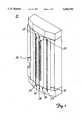
- FIG. 1is an isometric view of a recording head according to the present invention, illustrating the two slotted erase heads and the full-width write head.
- FIG. 2is an arranged view of the slots of the erase heads.
- FIG. 3is an overhead plan view of the device shown in FIG. 1, shown with a recording medium contacting the recording head.
- FIG. 4is a system block diagram showing the nature of the storage apparatus (recording head and recording medium) used with the invention.
- FIG. 5is an enlarged, fragmentary schematic view of the recording medium after being written to by the recording head according to the present invention.
- FIG. 6is an enlarged, fragmentary schematic view of the recording medium after having the servo burst pattern erased out by the recording head according to the present invention.
- the recording head 10in the most preferred embodiment of the present invention, for providing the servo signal pattern shown in FIG. 6, will now be described with reference to FIGS. 1-2.
- the recording head 10has a core made from a Hot Isostatic Process (HIP'ed) nickel-zinc ferrite material and has a transducer with a full-width (0.4 inch) write head 12 and two full width servo erase heads 14 and 16, having multiple slotted regions 21 and 22 formed therein.
- the recording head 10also contains a read head 18 preferably having a width over a range of at least 0.0080 inch to 0.0120 inch, and optimally 0.0100 inch.
- the servo erase heads 14 and 16are positioned on the transducer so that their magnetic erase gaps 24 and 25, respectively, are spaced apart from each other by at least 0.365 inch to 0.0385 inch, and optimally 0.0375 inch.
- the write head 12is positioned relative to the nearest erase head 16 such that the magnetic write gap 23 of the write head 12 is separated by a distance of at least 0.0590 inch to 0.0610 inch, and optimally 0.0600 inch from the magnetic erase gap 24 of the nearest servo erase head 16.
- the magnetic write gap 23 of the write head 12extends across the entire width of the recording head 10.
- the multiple slotted regions 21 and 22 formed on servo erase heads 16 and 14, respectively,extend substantially in parallel to one another along the width of the recording head 10.
- the slotted regions 21 and 22preferably have a width over a range of 0.0038 inch to 0.0040 inch, and optimally 0.0039 inch, and a pitch along the width of the recording head 10 over a range of 0.0077 inch to 0.0079 inch, and optimally 0.0078 inch.
- Servo erase heads 14 and 16are substantially identical, and accordingly, only erase head 14 will be described in greater detail hereinafter. It is to be understood that the description of the servo erase head 14 applies equally to the other servo erase head 16 aside from the differences pointed out below.
- the slotted portion 22 of erase head 14is formed by machining slots 28 into the erase head 14, then back-filling the slots 28 with glass or other suitable substances.
- the slots 28 of slotted region 22preferably have a total width over a range of at least 0.0038 inch to 0.0040 inch, and optimally 0.0039 inch, and the pattern of the slotted region 22 along the servo erase head 14 is laid out so that the slots 28 have a pitch along the width of the servo erase head 14 of at least 0.0077 inch to 0.0079 inch, and optimally 0.0078 inch. As further seen in FIG.
- the slotted region 21 on the servo erase head 16is aligned relative to the slotted region 22 on the servo erase head 14 such that these regions are offset over a range of at least 0.0038 inch to 0.0040 inch, and optimally 0.0039 inch, so that the width, pitch and alignment will determine the track pitch and alignment of the final desired servo burst pattern.
- the slotted region 21 of servo erase head 16is also formed by machining slots 28a into servo erase head 16, then back-filling the machined slot 28a with glass or other suitable substances.
- the micro-controller 30which controls the operation of the write head 12, the servo erase heads 14 and 16, and the read head 18 is shown in schematic form in FIG. 4.
- the micro-controller 30sends control signals to a plurality of state machines located in programmable array logic (PAL) circuit 32 via signal lines 40a-c.
- PALprogrammable array logic
- the output of one state machine contained within the PAL 32is sent to the write driver 34 via line 42, whose output is sent to the write head 12 on the recording head 10 via line 46.
- the output of the other two state machines contained within the PAL 32are sent to the A-erase driver 35 and the B-erase driver 36 via lines 43 and 44, respectively.
- the outputs from the A-erase driver 35 and the B-erase driver 36are sent to servo erase heads 14 and 16 via lines 47 and 48, respectively, for controlling the erasing of the bursts on the recording medium.
- a cycle count signal from the PAL 32which informs the microcontroller 30 of how many servo burst patterns have been formed on the recording medium, is fed back to the micro-controller 30 via line 41.
- the micro-controller 30also reads back calibration signal information from the read head 18 which transmits the information signal from the recording head 10 via line 49 to the Read Preamp/filter circuit 37, which transmits the information to the micro-controller 30 via line 45.
- the operation of the data recorder mechanism 38is also controlled by the micro-controller 30 via line 60.
- the control of the data recorder 38is understood by those of ordinary skill in the art and shall not be discussed further herein.
- the data recorder mechanism 38detects the end of tape (EOT) hole of the recording medium 50.
- the EOT detection signalis then transmitted to the micro-controller 30 which transmits a signal on line 42 to the write driver 34, which then sends an activation signal to the write head 12 via line 46.
- the magnetic write gap 23is energized and writes a magnetic stripe 48 preferably having a length over a range of at least 0.017 inch to 0.023 inch, and optimally 0.020 inch on the storage surface 51 of the recording medium 50.
- the write head 12is then deactivated long enough to leave a 0.0070 inch to 0.0130 inch, and optimally a 0.010 inch long gap 60 on the storage surface 51 of the recording medium 50.
- the write head 12is then reactivated and the magnetic write gap 23 is energized to write another magnetic stripe 49 preferably having a length over a range of at least 0.0570 inch to 0.0630 inch, and optimally 0.06 inch onto the storage surface 51 of the recording medium 50.
- the write head 12is then deactivated long enough to leave another gap 60 preferably having a length over a range of at least 0.0070 inch to 0.0130 inch, and optimally 0.010 inch on the storage surface 51 of the recording medium 50.
- This pattern of approximately 0.02 inch stripe, approximately 0.01 inch gap, approximately 0.06 inch stripe, and approximately 0.01 inch gapis repeated until there are a total of 575 such patterns written on the storage surface 51 of the recording medium 50.
- the micro-controller 30transmits control signals to the PAL 32 via lines 40 which activate the A-erase driver 35 and B-erase driver 36, via lines 43 and 44, respectively, which further activate the servo erase heads 14 and 16, respectively.
- the magnetic erase gap 24is energized and proceeds to erase out a void pattern preferably having a length over a range of at least 0.0270 inch to 0.0330 inch, and optimally 0.030 inch on the storage surface 51 of the recording medium 50 which represented by the area "A" in FIG. 6.
- the magnetic erase gap 24 of the servo erase head 14is energized, and proceeds to erase out a void pattern preferably having a length over a range of 0.0270 inch to 0.0330 inch, and optimally 0.030 inch on the storage surface 51 of the recording medium 50 which further represented by the area "B" in FIG. 6.
- the PAL 32is programmable with adjustments to the exact timing between the write head 12 and the servo erase heads 14 and 16, so that mechanical tolerances on the recording head 10 and the data recorder mechanism 38 may be compensated for, thereby resulting in the accurate generation of the servo burst pattern 70 shown in FIG. 6.
Landscapes
- Adjustment Of The Magnetic Head Position Track Following On Tapes (AREA)
- Moving Of The Head To Find And Align With The Track (AREA)
Abstract
Description
Claims (39)
Priority Applications (6)
| Application Number | Priority Date | Filing Date | Title |
|---|---|---|---|
| US08/361,773US5602703A (en) | 1994-12-27 | 1994-12-27 | Recording head for recording track-centering servo signals on a multi-track recording medium |
| DE69508279TDE69508279T2 (en) | 1994-12-27 | 1995-12-19 | RECORDING HEAD FOR RECORDING TRACK-CENTER SERVO SIGNALS ON A MULTI-TRACK RECORDING MEDIUM |
| PCT/US1995/016499WO1996019799A2 (en) | 1994-12-22 | 1995-12-19 | Recording head for recording track-centering servo signals on a multi-track recording medium |
| JP51993296AJP3833705B2 (en) | 1994-12-27 | 1995-12-19 | Recording head for recording a track centering servo signal on a multi-track recording medium |
| KR1019970704350AKR100369726B1 (en) | 1994-12-22 | 1995-12-19 | Recording head for recording track-centering servo signals on a multi-track recording medium |
| EP95944493AEP0799474B1 (en) | 1994-12-22 | 1995-12-19 | Recording head for recording track-centering servo signals on a multi-track recording medium |
Applications Claiming Priority (1)
| Application Number | Priority Date | Filing Date | Title |
|---|---|---|---|
| US08/361,773US5602703A (en) | 1994-12-27 | 1994-12-27 | Recording head for recording track-centering servo signals on a multi-track recording medium |
Publications (1)
| Publication Number | Publication Date |
|---|---|
| US5602703Atrue US5602703A (en) | 1997-02-11 |
Family
ID=23423394
Family Applications (1)
| Application Number | Title | Priority Date | Filing Date |
|---|---|---|---|
| US08/361,773Expired - LifetimeUS5602703A (en) | 1994-12-22 | 1994-12-27 | Recording head for recording track-centering servo signals on a multi-track recording medium |
Country Status (6)
| Country | Link |
|---|---|
| US (1) | US5602703A (en) |
| EP (1) | EP0799474B1 (en) |
| JP (1) | JP3833705B2 (en) |
| KR (1) | KR100369726B1 (en) |
| DE (1) | DE69508279T2 (en) |
| WO (1) | WO1996019799A2 (en) |
Cited By (34)
| Publication number | Priority date | Publication date | Assignee | Title |
|---|---|---|---|---|
| US5864451A (en)* | 1996-07-31 | 1999-01-26 | Mitsumi Electric Co., Ltd. | Magnetic tape head having longitudinal track width restriction grooves |
| US5883770A (en)* | 1997-07-18 | 1999-03-16 | International Business Machines Corporation | Partial width mass produced linear tape recording head |
| WO1999027528A1 (en)* | 1997-11-21 | 1999-06-03 | Storage Technology Corporation | Multi-track, bi-directional, high speed thin film tape head assembly |
| US5953184A (en)* | 1997-09-30 | 1999-09-14 | Storage Technology Corporation | Transverse slotted magnetic tape head assembly |
| US5963401A (en)* | 1997-09-29 | 1999-10-05 | Storage Technology Corporation | Magnetic tape head assembly including modules having a plurality of magneto-resistive head elements |
| US6018444A (en)* | 1997-10-28 | 2000-01-25 | Hewlett-Packard Company | Batch fabricated servo write head having low write-gap linewidth variation |
| US6043951A (en)* | 1996-09-02 | 2000-03-28 | Samsung Electronics Co., Ltd. | Method, apparatus, and magnetic disk for optimizing off-track position of a magnetoresistive head |
| US6134070A (en)* | 1997-05-22 | 2000-10-17 | Imation Corp. | Encoded servo track configurations, servo writer and systems/method regarding same |
| US6172837B1 (en) | 1998-03-23 | 2001-01-09 | Hewlett-Packard Company | Postponable servo code selection |
| US6236525B1 (en)* | 1998-08-14 | 2001-05-22 | Storage Technology Corporation | Tape head with pattern timing for servo writing application |
| US20020075594A1 (en)* | 2000-12-11 | 2002-06-20 | Fujitsu Limited | Read/write head for a magnetic tape device having grooves for reducing tape floating |
| US6433959B1 (en) | 2000-10-30 | 2002-08-13 | Storage Technology Corporation | Tape head contour utilizing enclosed through slots |
| US20040032685A1 (en)* | 2002-04-30 | 2004-02-19 | Storage Technology Corporation | Timing based servo pattern incorporating band encoding |
| US20040095674A1 (en)* | 2002-11-15 | 2004-05-20 | Imation Corp. | Contoured magnetic head for linear tape |
| US20050018349A1 (en)* | 2003-07-25 | 2005-01-27 | Eaton James Howard | Recording head compensation for tape shrinkage and expansion |
| US6849148B2 (en) | 2001-02-28 | 2005-02-01 | Lafe Technology Limited | Thin film magnetic tape head and method of manufacturing therefor |
| US20050157422A1 (en)* | 2003-12-19 | 2005-07-21 | Dugas Matthew P. | Timing-based servo verify head and method thereof |
| KR100630772B1 (en) | 2005-11-10 | 2006-10-04 | 삼성전자주식회사 | Track error checking method and device |
| US7130140B1 (en) | 2002-05-06 | 2006-10-31 | Storage Technology Corporation | Polarity encoded pattern for timing based servo |
| US20070047122A1 (en)* | 2005-08-30 | 2007-03-01 | International Business Machines Corporation | Tape head having write devices and narrower read devices |
| US20090097155A1 (en)* | 1999-02-23 | 2009-04-16 | Advanced Research Corporation | Magnetic media having a servo track written with a patterned magnetic recording head |
| US20090161249A1 (en)* | 2007-12-19 | 2009-06-25 | Sony Corporation | Magnetic tape, magnetic tape apparatus, servo pattern recording apparatus, magnetic tape producing method, and magnetic tape recording method |
| US20090262456A1 (en)* | 2008-03-28 | 2009-10-22 | Dugas Matthew P | Method of formatting magnetic media using a thin film planar arbitrary gap pattern magnetic head |
| US20090262452A1 (en)* | 1999-12-30 | 2009-10-22 | Dugas Matthew P | Multichannel time based servo tape media |
| US7751148B1 (en)* | 2006-03-27 | 2010-07-06 | Oracle America, Inc. | Multi-level, multi-track magnetic recording head |
| US20100284105A1 (en)* | 2004-01-30 | 2010-11-11 | Dugas Matthew P | Apparatuses and methods for pre-erasing during manufacture of magnetic tape |
| US20100296192A1 (en)* | 1999-02-23 | 2010-11-25 | Advanced Research Corporation | Patterned magnetic recording head with termination pattern |
| US20100321824A1 (en)* | 2004-02-18 | 2010-12-23 | Dugas Matthew P | Magnetic recording head having secondary sub-gaps |
| US20110002065A1 (en)* | 2008-01-23 | 2011-01-06 | Dugas Matthew P | Recording heads with embedded tape guides and magnetic media made by such recording heads |
| US20110043940A1 (en)* | 2009-07-31 | 2011-02-24 | Gregory Lawrence Wagner | Erase drive system and methods of erasure for tape data cartridge |
| US20110141604A1 (en)* | 2004-05-04 | 2011-06-16 | Dugas Matthew P | Magnetic media formatted with an intergrated thin film subgap subpole structure for arbitrary gap pattern magnetic recording head |
| US20110181982A1 (en)* | 2010-01-22 | 2011-07-28 | Fujifilm Corporation | Servo write head, servo writer, and method for manufacturing magnetic tape with servo signal written thereon |
| USD756452S1 (en)* | 2014-08-01 | 2016-05-17 | Wilson Tool International Inc. | Cartridge |
| US20240185883A1 (en)* | 2021-03-31 | 2024-06-06 | Sony Group Corporation | Magnetic head, servo pattern recording apparatus, tape drive device, method of producing a magnetic tape, and recording method |
Families Citing this family (1)
| Publication number | Priority date | Publication date | Assignee | Title |
|---|---|---|---|---|
| US6605681B1 (en) | 2000-07-12 | 2003-08-12 | Johnson Polymer, Inc. | Process for the continuous production of epoxylated addition polymers, and powder and liquid coating applications containing epoxylated addition polymers |
Citations (15)
| Publication number | Priority date | Publication date | Assignee | Title |
|---|---|---|---|---|
| US4107751A (en)* | 1975-05-26 | 1978-08-15 | Olympus Optical Co., Ltd. | Magnetic head |
| EP0069548A1 (en)* | 1981-07-02 | 1983-01-12 | Irwin International, Inc. | Data record with pre-recorded transducer positioning signals, and system for utilizing same |
| JPS62273615A (en)* | 1986-05-21 | 1987-11-27 | Nec Corp | Recording and reproducing head for magnetic tape |
| WO1989009466A1 (en)* | 1988-03-22 | 1989-10-05 | Carlisle Memory Products Group Incorporated | Bimodal multi-track magnetic head |
| US4996609A (en)* | 1989-02-22 | 1991-02-26 | Pericomp Corporation | Magnetic head recording multitrack servo patterns |
| US5121270A (en)* | 1989-09-19 | 1992-06-09 | Alcudia Ezra R | Multitransducer head positioning servo for use in a bi-directional magnetic tape system |
| EP0517531A2 (en)* | 1991-06-07 | 1992-12-09 | Minnesota Mining And Manufacturing Company | Multi-track servo recording head, resultant media containing pre-recorded servo track, and servo controlled head positioning system |
| US5229895A (en)* | 1991-06-07 | 1993-07-20 | Minnesota Mining And Manufacturing Company | Multi-track servo recording head assembly |
| EP0562563A2 (en)* | 1992-03-23 | 1993-09-29 | Conner Peripherals, Inc. | Multi-track embedded servo recording format and method |
| US5307217A (en)* | 1992-06-24 | 1994-04-26 | Digital Equipment Corporation | Magnetic head for very high track density magnetic recording |
| US5321570A (en)* | 1989-10-02 | 1994-06-14 | Behr Michael I | Systems using superimposed, orthogonal buried servo signals |
| EP0630001A2 (en)* | 1993-06-14 | 1994-12-21 | International Business Machines Corporation | Method and apparatus for initialization and calibration of magnetic tape having multiple servo areas |
| US5394285A (en)* | 1993-07-21 | 1995-02-28 | Storage Technology Corporation | Multi-track longitudinal, metal-in-gap head |
| US5408366A (en)* | 1993-06-14 | 1995-04-18 | International Business Machines Corporation | Apparatus and method for detecting and validating formatted blocks on magnetic tape |
| US5453887A (en)* | 1987-01-13 | 1995-09-26 | Canon Denshi Kabushiki Kaisha | Head tracking servo pattern |
- 1994
- 1994-12-27USUS08/361,773patent/US5602703A/ennot_activeExpired - Lifetime
- 1995
- 1995-12-19KRKR1019970704350Apatent/KR100369726B1/ennot_activeExpired - Fee Related
- 1995-12-19WOPCT/US1995/016499patent/WO1996019799A2/enactiveIP Right Grant
- 1995-12-19DEDE69508279Tpatent/DE69508279T2/ennot_activeExpired - Fee Related
- 1995-12-19EPEP95944493Apatent/EP0799474B1/ennot_activeExpired - Lifetime
- 1995-12-19JPJP51993296Apatent/JP3833705B2/ennot_activeExpired - Fee Related
Patent Citations (16)
| Publication number | Priority date | Publication date | Assignee | Title |
|---|---|---|---|---|
| US4107751A (en)* | 1975-05-26 | 1978-08-15 | Olympus Optical Co., Ltd. | Magnetic head |
| EP0069548A1 (en)* | 1981-07-02 | 1983-01-12 | Irwin International, Inc. | Data record with pre-recorded transducer positioning signals, and system for utilizing same |
| JPS62273615A (en)* | 1986-05-21 | 1987-11-27 | Nec Corp | Recording and reproducing head for magnetic tape |
| US5453887A (en)* | 1987-01-13 | 1995-09-26 | Canon Denshi Kabushiki Kaisha | Head tracking servo pattern |
| WO1989009466A1 (en)* | 1988-03-22 | 1989-10-05 | Carlisle Memory Products Group Incorporated | Bimodal multi-track magnetic head |
| US4979051A (en)* | 1988-03-22 | 1990-12-18 | Eggebeen James A | Bimodal multi-track magnetic head |
| US4996609A (en)* | 1989-02-22 | 1991-02-26 | Pericomp Corporation | Magnetic head recording multitrack servo patterns |
| US5121270A (en)* | 1989-09-19 | 1992-06-09 | Alcudia Ezra R | Multitransducer head positioning servo for use in a bi-directional magnetic tape system |
| US5321570A (en)* | 1989-10-02 | 1994-06-14 | Behr Michael I | Systems using superimposed, orthogonal buried servo signals |
| US5229895A (en)* | 1991-06-07 | 1993-07-20 | Minnesota Mining And Manufacturing Company | Multi-track servo recording head assembly |
| EP0517531A2 (en)* | 1991-06-07 | 1992-12-09 | Minnesota Mining And Manufacturing Company | Multi-track servo recording head, resultant media containing pre-recorded servo track, and servo controlled head positioning system |
| EP0562563A2 (en)* | 1992-03-23 | 1993-09-29 | Conner Peripherals, Inc. | Multi-track embedded servo recording format and method |
| US5307217A (en)* | 1992-06-24 | 1994-04-26 | Digital Equipment Corporation | Magnetic head for very high track density magnetic recording |
| EP0630001A2 (en)* | 1993-06-14 | 1994-12-21 | International Business Machines Corporation | Method and apparatus for initialization and calibration of magnetic tape having multiple servo areas |
| US5408366A (en)* | 1993-06-14 | 1995-04-18 | International Business Machines Corporation | Apparatus and method for detecting and validating formatted blocks on magnetic tape |
| US5394285A (en)* | 1993-07-21 | 1995-02-28 | Storage Technology Corporation | Multi-track longitudinal, metal-in-gap head |
Cited By (60)
| Publication number | Priority date | Publication date | Assignee | Title |
|---|---|---|---|---|
| US5864451A (en)* | 1996-07-31 | 1999-01-26 | Mitsumi Electric Co., Ltd. | Magnetic tape head having longitudinal track width restriction grooves |
| US6043951A (en)* | 1996-09-02 | 2000-03-28 | Samsung Electronics Co., Ltd. | Method, apparatus, and magnetic disk for optimizing off-track position of a magnetoresistive head |
| US6134070A (en)* | 1997-05-22 | 2000-10-17 | Imation Corp. | Encoded servo track configurations, servo writer and systems/method regarding same |
| US6341416B1 (en) | 1997-07-18 | 2002-01-29 | International Business Machines Corporation | Method for mass producing partial width linear tape recording head |
| US5883770A (en)* | 1997-07-18 | 1999-03-16 | International Business Machines Corporation | Partial width mass produced linear tape recording head |
| US5963401A (en)* | 1997-09-29 | 1999-10-05 | Storage Technology Corporation | Magnetic tape head assembly including modules having a plurality of magneto-resistive head elements |
| US5953184A (en)* | 1997-09-30 | 1999-09-14 | Storage Technology Corporation | Transverse slotted magnetic tape head assembly |
| US7206167B2 (en)* | 1997-10-28 | 2007-04-17 | Hewlett-Packard Development Company, L.P. | Servo write method for magnetic tape |
| US6018444A (en)* | 1997-10-28 | 2000-01-25 | Hewlett-Packard Company | Batch fabricated servo write head having low write-gap linewidth variation |
| US20050068668A1 (en)* | 1997-10-28 | 2005-03-31 | Beck Patricia A. | Batch fabricated servo write head |
| US6038108A (en)* | 1997-11-21 | 2000-03-14 | Storage Technology Corporation | Magnetic tape head assembly having segmented heads |
| WO1999027528A1 (en)* | 1997-11-21 | 1999-06-03 | Storage Technology Corporation | Multi-track, bi-directional, high speed thin film tape head assembly |
| US6172837B1 (en) | 1998-03-23 | 2001-01-09 | Hewlett-Packard Company | Postponable servo code selection |
| US6411460B1 (en)* | 1998-03-23 | 2002-06-25 | Hewlett-Packard Co. | Postponable servo code selection |
| US6236525B1 (en)* | 1998-08-14 | 2001-05-22 | Storage Technology Corporation | Tape head with pattern timing for servo writing application |
| US20090097155A1 (en)* | 1999-02-23 | 2009-04-16 | Advanced Research Corporation | Magnetic media having a servo track written with a patterned magnetic recording head |
| US20100296192A1 (en)* | 1999-02-23 | 2010-11-25 | Advanced Research Corporation | Patterned magnetic recording head with termination pattern |
| US8542457B2 (en) | 1999-12-30 | 2013-09-24 | Advanced Research Corporation | Method of making a multi-channel time based servo tape media |
| US7948705B2 (en) | 1999-12-30 | 2011-05-24 | Advanced Research Corporation | Method of making a multi-channel time based servo tape media |
| US20100002335A1 (en)* | 1999-12-30 | 2010-01-07 | Dugas Matthew P | Method of making a multi-channel time based servo tape media |
| US20090262452A1 (en)* | 1999-12-30 | 2009-10-22 | Dugas Matthew P | Multichannel time based servo tape media |
| US8254052B2 (en) | 1999-12-30 | 2012-08-28 | Advanced Research Corporation | Method of making a multi-channel time based servo tape media |
| US8437103B2 (en) | 1999-12-30 | 2013-05-07 | Advanced Research Corporation | Multichannel time based servo tape media |
| US6433959B1 (en) | 2000-10-30 | 2002-08-13 | Storage Technology Corporation | Tape head contour utilizing enclosed through slots |
| US6927937B2 (en)* | 2000-12-11 | 2005-08-09 | Fujitsu Limited | Read/write head for a magnetic tape device having grooves for reducing tape floating |
| US20020075594A1 (en)* | 2000-12-11 | 2002-06-20 | Fujitsu Limited | Read/write head for a magnetic tape device having grooves for reducing tape floating |
| US6849148B2 (en) | 2001-02-28 | 2005-02-01 | Lafe Technology Limited | Thin film magnetic tape head and method of manufacturing therefor |
| US20040032685A1 (en)* | 2002-04-30 | 2004-02-19 | Storage Technology Corporation | Timing based servo pattern incorporating band encoding |
| US6912104B2 (en) | 2002-04-30 | 2005-06-28 | Storage Technology Corporation | Timing based servo pattern incorporating band encoding |
| US7130140B1 (en) | 2002-05-06 | 2006-10-31 | Storage Technology Corporation | Polarity encoded pattern for timing based servo |
| US20040095674A1 (en)* | 2002-11-15 | 2004-05-20 | Imation Corp. | Contoured magnetic head for linear tape |
| US7050264B2 (en)* | 2002-11-15 | 2006-05-23 | Imation Corp. | Linear magnetic tape head with tape contact area projected minimal height above non-rotating contoured head surface |
| US7193812B2 (en)* | 2003-07-25 | 2007-03-20 | International Business Machines Corporation | Recording head compensation for tape shrinkage and expansion |
| US20050018349A1 (en)* | 2003-07-25 | 2005-01-27 | Eaton James Howard | Recording head compensation for tape shrinkage and expansion |
| US20050157422A1 (en)* | 2003-12-19 | 2005-07-21 | Dugas Matthew P. | Timing-based servo verify head and method thereof |
| US8144424B2 (en)* | 2003-12-19 | 2012-03-27 | Dugas Matthew P | Timing-based servo verify head and magnetic media made therewith |
| US20100284105A1 (en)* | 2004-01-30 | 2010-11-11 | Dugas Matthew P | Apparatuses and methods for pre-erasing during manufacture of magnetic tape |
| US20100321824A1 (en)* | 2004-02-18 | 2010-12-23 | Dugas Matthew P | Magnetic recording head having secondary sub-gaps |
| US20110141604A1 (en)* | 2004-05-04 | 2011-06-16 | Dugas Matthew P | Magnetic media formatted with an intergrated thin film subgap subpole structure for arbitrary gap pattern magnetic recording head |
| US8416525B2 (en) | 2004-05-04 | 2013-04-09 | Advanced Research Corporation | Magnetic media formatted with an intergrated thin film subgap subpole structure for arbitrary gap pattern magnetic recording head |
| CN100409312C (en)* | 2005-08-30 | 2008-08-06 | 国际商业机器公司 | Magnetic head for reading magnetic recording tape, tape driving system and method |
| US20070047122A1 (en)* | 2005-08-30 | 2007-03-01 | International Business Machines Corporation | Tape head having write devices and narrower read devices |
| KR100630772B1 (en) | 2005-11-10 | 2006-10-04 | 삼성전자주식회사 | Track error checking method and device |
| US7751148B1 (en)* | 2006-03-27 | 2010-07-06 | Oracle America, Inc. | Multi-level, multi-track magnetic recording head |
| US8089716B2 (en) | 2007-12-19 | 2012-01-03 | Sony Corporation | Magnetic tape, magnetic tape apparatus, servo pattern recording apparatus, magnetic tape producing method, and magnetic tape recording method |
| US20090161249A1 (en)* | 2007-12-19 | 2009-06-25 | Sony Corporation | Magnetic tape, magnetic tape apparatus, servo pattern recording apparatus, magnetic tape producing method, and magnetic tape recording method |
| US20110002065A1 (en)* | 2008-01-23 | 2011-01-06 | Dugas Matthew P | Recording heads with embedded tape guides and magnetic media made by such recording heads |
| US20090262456A1 (en)* | 2008-03-28 | 2009-10-22 | Dugas Matthew P | Method of formatting magnetic media using a thin film planar arbitrary gap pattern magnetic head |
| US8068302B2 (en) | 2008-03-28 | 2011-11-29 | Advanced Research Corporation | Method of formatting magnetic media using a thin film planar arbitrary gap pattern magnetic head |
| US8068301B2 (en) | 2008-03-28 | 2011-11-29 | Advanced Research Corporation | Magnetic media formed by a thin film planar arbitrary gap pattern magnetic head |
| US20100027164A1 (en)* | 2008-03-28 | 2010-02-04 | Dugas Matthew P | Magnetic media formed by a thin planar arbitrary gap pattern magnetic head |
| US8068300B2 (en) | 2008-03-28 | 2011-11-29 | Advanced Research Corporation | Thin film planar arbitrary gap pattern magnetic head |
| US20100027153A1 (en)* | 2008-03-28 | 2010-02-04 | Dugas Matthew P | Thin film planar arbitrary gap pattern magnetic head |
| US20110043940A1 (en)* | 2009-07-31 | 2011-02-24 | Gregory Lawrence Wagner | Erase drive system and methods of erasure for tape data cartridge |
| US8767331B2 (en) | 2009-07-31 | 2014-07-01 | Advanced Research Corporation | Erase drive system and methods of erasure for tape data cartridge |
| US20110181982A1 (en)* | 2010-01-22 | 2011-07-28 | Fujifilm Corporation | Servo write head, servo writer, and method for manufacturing magnetic tape with servo signal written thereon |
| US8451561B2 (en)* | 2010-01-22 | 2013-05-28 | Fujifilm Corporation | Servo write head, servo writer, and method for manufacturing magnetic tape with servo signal written thereon |
| USD756452S1 (en)* | 2014-08-01 | 2016-05-17 | Wilson Tool International Inc. | Cartridge |
| US20240185883A1 (en)* | 2021-03-31 | 2024-06-06 | Sony Group Corporation | Magnetic head, servo pattern recording apparatus, tape drive device, method of producing a magnetic tape, and recording method |
| US12406691B2 (en)* | 2021-03-31 | 2025-09-02 | Sony Group Corporation | Magnetic head, servo pattern recording apparatus, tape drive device, method of producing a magnetic tape, and recording method |
Also Published As
| Publication number | Publication date |
|---|---|
| EP0799474A2 (en) | 1997-10-08 |
| WO1996019799A2 (en) | 1996-06-27 |
| JPH10513296A (en) | 1998-12-15 |
| JP3833705B2 (en) | 2006-10-18 |
| EP0799474B1 (en) | 1999-03-10 |
| DE69508279T2 (en) | 1999-07-08 |
| WO1996019799A3 (en) | 1996-08-29 |
| DE69508279D1 (en) | 1999-04-15 |
| KR100369726B1 (en) | 2003-03-15 |
| KR987001119A (en) | 1998-04-30 |
Similar Documents
| Publication | Publication Date | Title |
|---|---|---|
| US5602703A (en) | Recording head for recording track-centering servo signals on a multi-track recording medium | |
| US5132861A (en) | Systems using superimposed, orthogonal buried servo signals | |
| US5229895A (en) | Multi-track servo recording head assembly | |
| US5321570A (en) | Systems using superimposed, orthogonal buried servo signals | |
| US5617269A (en) | System for recording track-centering servo signals on multi-track magnetic medium | |
| US4996609A (en) | Magnetic head recording multitrack servo patterns | |
| EP1476865B1 (en) | Timing based servo with fixed distances between transitions | |
| US6873487B2 (en) | Hybrid servopositioning systems | |
| US5008765A (en) | Method and apparatus for reading or writing on tape using a servo positioned multiple channel head | |
| US6989950B2 (en) | Magnetic tape and manufacturing method thereof, and servo writer and servo write method | |
| US5963400A (en) | Thin film tape head including split top pole | |
| EP0030256B1 (en) | Buried servo track data recording systems | |
| US5426543A (en) | Servo positioning system for magnetic recording media | |
| CA2070969A1 (en) | Multi-track embedded servo recording format and method | |
| HK71696A (en) | Positioning separate read and write heads in a disk file | |
| GB1571175A (en) | Magnetic transducer apparatus | |
| US5959812A (en) | Fringe field compensation system for multi-track servo recording head | |
| US6411460B1 (en) | Postponable servo code selection | |
| WO1994012975A1 (en) | Method and apparatus for tape track identification | |
| US5223994A (en) | System using superimposed, orthogonal buried servo signals | |
| US20050007700A1 (en) | Tape recording system and head device | |
| US20040207943A1 (en) | Magnetic tape and method of manufacturing magnetic tape, servo writer, and method of and apparatus for specifying servo band | |
| US7110211B2 (en) | Magnetic tape, magnetic tape cartridge, magnetic tape drive, and method for recording data on magnetic tape | |
| KR19990082393A (en) | A system for recording and reproducing information, a recording medium used in the system, and a magnetic recording head and apparatus for formatting the recording medium | |
| US3155949A (en) | Tunnel erase magnetic transducer |
Legal Events
| Date | Code | Title | Description |
|---|---|---|---|
| AS | Assignment | Owner name:CONNER PERIPHERALS, INC., CALIFORNIA Free format text:ASSIGNMENT OF ASSIGNORS INTEREST;ASSIGNORS:MOORE, JOHN;LARSEN, KEITH;REEL/FRAME:007423/0006 Effective date:19950125 | |
| AS | Assignment | Owner name:SEAGATE TECHNOLOGY, INC., CALIFORNIA Free format text:ASSIGNMENT OF ASSIGNORS INTEREST;ASSIGNOR:CONNER PERIPHERALS, INC.;REEL/FRAME:008271/0512 Effective date:19961122 | |
| STCF | Information on status: patent grant | Free format text:PATENTED CASE | |
| CC | Certificate of correction | ||
| FEPP | Fee payment procedure | Free format text:PAYOR NUMBER ASSIGNED (ORIGINAL EVENT CODE: ASPN); ENTITY STATUS OF PATENT OWNER: LARGE ENTITY | |
| FPAY | Fee payment | Year of fee payment:4 | |
| AS | Assignment | Owner name:SEAGATE REMOVABLE STORAGE SOLUTIONS LLC, CALIFORNI Free format text:ASSIGNMENT OF ASSIGNORS INTEREST;ASSIGNOR:SEAGATE TECHNOLOGY, INC.;REEL/FRAME:011111/0459 Effective date:20000728 | |
| AS | Assignment | Owner name:CHASE MANHATTAN BANK, AS COLLATERAL AGENT, THE, NE Free format text:SECURITY AGREEMENT;ASSIGNOR:SEAGATE REMOVABLE STORAGE SOLUTIONS LLC;REEL/FRAME:011436/0001 Effective date:20001122 | |
| FEPP | Fee payment procedure | Free format text:PAYOR NUMBER ASSIGNED (ORIGINAL EVENT CODE: ASPN); ENTITY STATUS OF PATENT OWNER: LARGE ENTITY Free format text:PAYER NUMBER DE-ASSIGNED (ORIGINAL EVENT CODE: RMPN); ENTITY STATUS OF PATENT OWNER: LARGE ENTITY | |
| FEPP | Fee payment procedure | Free format text:PAYER NUMBER DE-ASSIGNED (ORIGINAL EVENT CODE: RMPN); ENTITY STATUS OF PATENT OWNER: LARGE ENTITY Free format text:PAYOR NUMBER ASSIGNED (ORIGINAL EVENT CODE: ASPN); ENTITY STATUS OF PATENT OWNER: LARGE ENTITY | |
| REMI | Maintenance fee reminder mailed | ||
| FPAY | Fee payment | Year of fee payment:8 | |
| SULP | Surcharge for late payment | Year of fee payment:7 | |
| AS | Assignment | Owner name:CERTANCE LLC (FORMERLY SEAGATE REMOVABLE STORAGE S Free format text:RELEASE;ASSIGNOR:JPMORGAN CHASE BANK;REEL/FRAME:015918/0321 Effective date:20041101 | |
| AS | Assignment | Owner name:CERTANCE LLC, CALIFORNIA Free format text:ASSIGNMENT OF ASSIGNORS INTEREST;ASSIGNOR:SEAGATE REMOVABLE STORAGE SOLUTIONS, LLC;REEL/FRAME:018260/0302 Effective date:20030401 | |
| AS | Assignment | Owner name:KEYBANK NATIONAL ASSOCIATION, AS ADMINISTRATIVE AG Free format text:INTELLECTUAL PROPERTY SECURITY AGREEMENT (SECOND LIEN);ASSIGNOR:QUANTUM CORPORATION;REEL/FRAME:018268/0475 Effective date:20060822 | |
| AS | Assignment | Owner name:KEYBANK NATIONAL ASSOCIATION, AS ADMINISTRATIVE AG Free format text:INTELLECTUAL PROPERTY SECURITY AGREEMENT (FIRST LIEN);ASSIGNOR:QUANTUM CORPORATION;REEL/FRAME:018303/0336 Effective date:20060822 | |
| AS | Assignment | Owner name:CERTANCE LLC, CALIFORNIA Free format text:CHANGE OF NAME;ASSIGNOR:SEAGATE REMOVABLE STORAGE SOLUTIONS LLC;REEL/FRAME:019529/0409 Effective date:20030407 | |
| AS | Assignment | Owner name:QUANTUM CORPORATION, CALIFORNIA Free format text:TERMINATION OF SECURITY INTEREST IN PATENTS REEL 018269 FRAME 0005 AND REEL 018268 FRAME 0475;ASSIGNOR:KEY BANK, NATIONAL ASSOCIATION;REEL/FRAME:019550/0659 Effective date:20070712 Owner name:QUANTUM CORPORATION,CALIFORNIA Free format text:TERMINATION OF SECURITY INTEREST IN PATENTS REEL 018269 FRAME 0005 AND REEL 018268 FRAME 0475;ASSIGNOR:KEY BANK, NATIONAL ASSOCIATION;REEL/FRAME:019550/0659 Effective date:20070712 | |
| AS | Assignment | Owner name:QUANTUM CORPORATION, CALIFORNIA Free format text:RELEASE OF INTELLECTUAL PROPERTY SECURITY AGREEMENT AT REEL 018303 FRAME 0336;ASSIGNOR:KEYBANK NATIONAL ASSOCIATION;REEL/FRAME:019562/0958 Effective date:20070712 | |
| AS | Assignment | Owner name:CREDIT SUISSE, NEW YORK Free format text:SECURITY AGREEMENT;ASSIGNORS:QUANTUM CORPORATION;ADVANCED DIGITAL INFORMATION CORPORATION;CERTANCE HOLDINGS CORPORATION;AND OTHERS;REEL/FRAME:019605/0159 Effective date:20070712 Owner name:CREDIT SUISSE,NEW YORK Free format text:SECURITY AGREEMENT;ASSIGNORS:QUANTUM CORPORATION;ADVANCED DIGITAL INFORMATION CORPORATION;CERTANCE HOLDINGS CORPORATION;AND OTHERS;REEL/FRAME:019605/0159 Effective date:20070712 | |
| FPAY | Fee payment | Year of fee payment:12 | |
| AS | Assignment | Owner name:QUANTUM CORPORATION, CALIFORNIA Free format text:PATENT ASSIGNMENT;ASSIGNOR:CERTANCE LLC;REEL/FRAME:027949/0836 Effective date:20120328 | |
| AS | Assignment | Owner name:QUANTUM INTERNATIONAL, INC., WASHINGTON Free format text:RELEASE BY SECURED PARTY;ASSIGNOR:CREDIT SUISSE, CAYMAN ISLANDS BRANCH (FORMERLY KNOWN AS CREDIT SUISSE), AS COLLATERAL AGENT;REEL/FRAME:027968/0007 Effective date:20120329 Owner name:QUANTUM CORPORATION, WASHINGTON Free format text:RELEASE BY SECURED PARTY;ASSIGNOR:CREDIT SUISSE, CAYMAN ISLANDS BRANCH (FORMERLY KNOWN AS CREDIT SUISSE), AS COLLATERAL AGENT;REEL/FRAME:027968/0007 Effective date:20120329 Owner name:WELLS FARGO CAPITAL FINANCE, LLC, AS AGENT, CALIFO Free format text:SECURITY AGREEMENT;ASSIGNOR:QUANTUM CORPORATION;REEL/FRAME:027967/0914 Effective date:20120329 Owner name:CERTANCE, LLC, WASHINGTON Free format text:RELEASE BY SECURED PARTY;ASSIGNOR:CREDIT SUISSE, CAYMAN ISLANDS BRANCH (FORMERLY KNOWN AS CREDIT SUISSE), AS COLLATERAL AGENT;REEL/FRAME:027968/0007 Effective date:20120329 Owner name:CERTANCE HOLDINGS CORPORATION, WASHINGTON Free format text:RELEASE BY SECURED PARTY;ASSIGNOR:CREDIT SUISSE, CAYMAN ISLANDS BRANCH (FORMERLY KNOWN AS CREDIT SUISSE), AS COLLATERAL AGENT;REEL/FRAME:027968/0007 Effective date:20120329 Owner name:CERTANCE (US) HOLDINGS, INC., WASHINGTON Free format text:RELEASE BY SECURED PARTY;ASSIGNOR:CREDIT SUISSE, CAYMAN ISLANDS BRANCH (FORMERLY KNOWN AS CREDIT SUISSE), AS COLLATERAL AGENT;REEL/FRAME:027968/0007 Effective date:20120329 Owner name:ADVANCED DIGITAL INFORMATION CORPORATION, WASHINGT Free format text:RELEASE BY SECURED PARTY;ASSIGNOR:CREDIT SUISSE, CAYMAN ISLANDS BRANCH (FORMERLY KNOWN AS CREDIT SUISSE), AS COLLATERAL AGENT;REEL/FRAME:027968/0007 Effective date:20120329 | |
| AS | Assignment | Owner name:QUANTUM CORPORATION, CALIFORNIA Free format text:RELEASE BY SECURED PARTY;ASSIGNOR:WELLS FARGO CAPITAL FINANCE, LLC, AS AGENT;REEL/FRAME:040474/0079 Effective date:20161021 |