US5602693A - Method and apparatus for sensing position in a disk drive - Google Patents
Method and apparatus for sensing position in a disk driveDownload PDFInfo
- Publication number
- US5602693A US5602693AUS08/355,649US35564994AUS5602693AUS 5602693 AUS5602693 AUS 5602693AUS 35564994 AUS35564994 AUS 35564994AUS 5602693 AUS5602693 AUS 5602693A
- Authority
- US
- United States
- Prior art keywords
- head
- burst
- signal
- magnitudes
- servo
- Prior art date
- Legal status (The legal status is an assumption and is not a legal conclusion. Google has not performed a legal analysis and makes no representation as to the accuracy of the status listed.)
- Expired - Lifetime
Links
- 238000000034methodMethods0.000titleclaimsdescription8
- 230000007704transitionEffects0.000claimsabstractdescription31
- 238000012937correctionMethods0.000claimsabstractdescription14
- 238000006073displacement reactionMethods0.000claimsabstractdescription14
- 230000004044responseEffects0.000claimsabstractdescription10
- 238000004364calculation methodMethods0.000claimsdescription17
- 238000012163sequencing techniqueMethods0.000claimsdescription4
- 238000001514detection methodMethods0.000claims5
- 238000005070samplingMethods0.000claims3
- 238000013500data storageMethods0.000description3
- 230000008901benefitEffects0.000description2
- 238000006243chemical reactionMethods0.000description2
- 230000006978adaptationEffects0.000description1
- 230000002411adverseEffects0.000description1
- 230000000712assemblyEffects0.000description1
- 238000000429assemblyMethods0.000description1
- 238000011161developmentMethods0.000description1
- 230000018109developmental processEffects0.000description1
- 238000012986modificationMethods0.000description1
- 230000004048modificationEffects0.000description1
- 238000012546transferMethods0.000description1
Images


Classifications
- G—PHYSICS
- G11—INFORMATION STORAGE
- G11B—INFORMATION STORAGE BASED ON RELATIVE MOVEMENT BETWEEN RECORD CARRIER AND TRANSDUCER
- G11B5/00—Recording by magnetisation or demagnetisation of a record carrier; Reproducing by magnetic means; Record carriers therefor
- G11B5/48—Disposition or mounting of heads or head supports relative to record carriers ; arrangements of heads, e.g. for scanning the record carrier to increase the relative speed
- G11B5/58—Disposition or mounting of heads or head supports relative to record carriers ; arrangements of heads, e.g. for scanning the record carrier to increase the relative speed with provision for moving the head for the purpose of maintaining alignment of the head relative to the record carrier during transducing operation, e.g. to compensate for surface irregularities of the latter or for track following
- G11B5/596—Disposition or mounting of heads or head supports relative to record carriers ; arrangements of heads, e.g. for scanning the record carrier to increase the relative speed with provision for moving the head for the purpose of maintaining alignment of the head relative to the record carrier during transducing operation, e.g. to compensate for surface irregularities of the latter or for track following for track following on disks
- G11B5/59633—Servo formatting
- G11B5/59655—Sector, sample or burst servo format
Definitions
- This inventiongenerally relates to hard disk drive systems, and more particularly to such systems utilizing servo information recorded on a disk surface for controlling the position of data read/write heads, and the accuracy in positioning such heads.
- Typical hard disk drive systemsrecord information on circular disks, each disk having a multiplicity of tracks concentrically located thereon.
- Each disk drivenormally contains a plurality of disks, each disk recording surface having one or more magnetic heads which transfer information to or from an external system.
- Each magnetic headis located on an arm, and all arms are aligned vertically and attached to a common head positioner assembly.
- the head positioner assemblyis driven by a motor so that the arms and magnetic heads move uniformly across the surfaces of the vertically aligned disks.
- Head positioner assembliesare usually mounted to rotate the arms and magnetic heads along an arcuate path over the disks.
- a host controllerissues a track seek command.
- the controller electronicsrespond to the track seek command, determining the direction and magnitude of movement necessary to drive the heads from their current position to the destination position.
- Hard disksare generally divided into a plurality of concentric tracks, and data is read or written along each track. Further, position of the head on each disk, position of data on each disk, and the desired destination for arm movement is indicated by track indices.
- High performance disk drive unitstypically attempt to maximize the density at which tracks are written. In order to achieve higher densities, the positioner motor is energized, and the data read/write head counts the number of tracks it crosses until it reaches the destination.
- the drive motoraccelerates to a maximum value for a calculated period of time and decelerates so that it attains zero velocity on reaching the destination.
- the carriage on which the heads are mountedis incorporated in a servo system, which performs the necessary positioning functions.
- a servo systemwhich has servo information located on one of many disk surfaces
- an embedded servo systemwherein each data surface is used to store the servo information
- the hybrid servo systemwhich uses a dedicated disk surface and a low sample rate embedded servo on each data surface to store servo information.
- the servo systemsenses the position of the heads by means of servo signals recorded in tracks on the disk surfaces.
- Embedded servo and hybrid servo system accuracy and data storagehas been the object of developments within the disk drive field, as the accuracy at which the head can be made to follow the track centerline determines the density of the tracks located on a disk. The closer the head can be made to follow the track centerline, the closer together the tracks can be spaced on the disk, and storage efficiency increases.
- a typical hard disk used in an embedded servo or hybrid servo systemhas a plurality of outwardly radiating "spokes” representing servo data. Each set of sectors between “spokes” represents zones where data is stored.
- Servo signalsare typically arranged in frames, including an AGC field, sync mark, cylinder information, and servo burst information.
- A, B, C, and Dare used to assist in positioning the heads, as the signals generated by the heads in reading these four burst groups determine the radial position of the head.
- Track centerline positionsare determined by the system by comparing the servo burst signals received. That is, knowing the placement of servo burst data on the disk, the position of a head traversing a track can be calculated from the signals received.
- strength of the signal generated in the servo transduceris a function of the actual gap width of the servo transducer, which affect the magnitudes of the servo burst signals (A, B, C, or D) received, introducing error into calculations which use these servo burst signals.
- prior compensation schemeswere inherently nonlinear, introducing unwanted position movement into the system.
- the present inventionis broadly directed to a system for positioning read/write heads traversing over disks in a disk drive system.
- the positioning systemincludes a servo pattern recorded on at least one disk.
- the servo patternhas a sequence of servo locations successively recorded along a plurality of concentric tracks on the disks.
- the servo patternalso has a series of burst zones, each burst zone having multiple transitions recorded at staggered separate radial distances from the center of the disks, and each burst zone radially shifted from other burst zones.
- the systemalso has magnitude calculation means for computing servo burst signal magnitudes based on head position relative to the transitions in each burst zone.
- the inventionfurther has signal determination means for calculating a head offset based on relative differences between servo burst signal magnitudes and radial displacement of each head in each track. Depending on the relative position of the head within a track, different burst amplitudes are received, and based on these amplitudes a correction signal based on calculated head offset is transmitted.
- the correction signalhas a linear response for any head position on the disk.
- the inventionis more specifically directed to a system for positioning a plurality of heads traversing multiple disks in a disk drive system wherein the positioning system includes a servo pattern recorded on at least one of the hard disks.
- the servo patternhas a sequence of servo locations successively recorded along concentric tracks on the disks. Burst zones are also recorded on the hard disks, each burst zone having multiple transitions recorded at staggered separate radial distances from the center of the disks.
- the positioning systemalso comprises means for computing servo burst signal magnitudes based on head position relative to the transitions in each burst zone, and means for calculating a head offset based on differences between the servo burst signal magnitudes and radial displacement of each head in each track.
- the positioning systemtransmits a correction signal based on calculated head position, and the output signal has a linear response for any head position on the disk. The linear response reduces unwanted position movement.
- signals receivedare demodulated to recover position information and convert the information into a position signal, and the current invention inhibits dc offsets. Further, head variations are minimized to avoid introducing error into calculations which use servo burst signals.
- FIG. 1illustrates a typical hard disk drive of the type in which the current invention is employed.
- FIG. 2shows a hard disk employed within a hard disk drive.
- FIG. 3presents the servo information contained within one "spoke" of a hard disk.
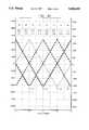
- FIG. 4Ais an illustration of burst amplitude received with respect to track position, and the corresponding calculations and transitions of the current system.
- FIG. 4Brepresents the output or calculation result of the configuration of FIG. 4A.
- FIG. 5presents the hardware implementation of the current invention.
- FIG. 6illustrates the mechanization of the burst comparator logic circuit.
- FIG. 1presents an illustration of a typical hard disk drive 11.
- the hard disk driveconsists of a head disk assembly, employing multiple disks 12, and a circuit board of controller electronics. Disks 12 may have information magnetically stored on the top and bottom surfaces. Data is read or written to the disks 12 using head 13.
- Embedded or hybrid servo systemsemploy hard disks having recorded thereon a plurality of "spokes” of servo data, illustrated in FIGS. 2 and 3.
- hard disk surface 20contains multiple outwardly radiating servo data "spokes” 21, with user data stored in data storage zones 22 which are located between the "spokes” 21.
- Each data storage zone 21 located on hard disk 20is located on a concentric data track 23.
- FIG. 3represents the data contained on a single servo data "spoke" 21 for fifteen separate tracks.
- Automatic gain control informationis contained in AGC field 33, which has multiple 37.5 nanosecond transitions located therein.
- sync mark data 34is located after AGC field 33.
- Two bits of index information 35precede a pad bit 36.
- four groups of cylinder information 37comprising a total of 16 bits of data, are located on each data track A through 0.
- the critical positioning informationfollows this cylinder information 37.
- Four groups of burst data, burst A 38, burst B 39, burst C 40 and burst D 41,are located radially outward from the center of the disk.
- Each group of burst data 38, 39, 40, and 41is offset from the other groups of burst data, and each group is uniformly radially positioned from the centerline of each track A through 0.
- Each burst group 38, 39, 40, and 41consists of 10 transition signals, each 37.5 nanoseconds in duration. While the preferred embodiment of the current invention employs four burst groups having ten transitions per burst group per track, it is to be understood that a different number of burst groups or a different number of transitions may be employed.
- the headwill read the top of the ten transitions of burst A 38, thus providing an intermediate strength signal to the data head, the bottom of the ten transitions of burst B 39, another intermediate strength signal, the center of burst C 40, yielding a very strong signal to the data head, and the head will read none of the ten transitions of burst D 41, supplying a minimal strength signal to the data head.
- data head position and correction factorscan be determined. If the data head is off center from the desired track, such as positioned "low" on track 0, burst A 38 will provide the maximum strength signal to the head, while burst B 39 will provide a relatively low strength signal to the head. Based on the information received from the head passing over these burst transition fields, correction of head position occurs.
- the present inventiondoes not use summation (A+B) to determine the relative head position, but uses a scheme involving the differences between pairs of the four servo burst signals 38, 39, 40, and 41 depending on the position of the head on the track.
- the amplitude information from all four servo burstsis used to generate the fine position information and is combined with the cylinder information to generate a digital position signal that is linear across the entire disk surface.
- a different equationis used to determine the head position.
- FIG. 4AThe passage of the heads over the four burst groups is shown in FIG. 4A, along with the equations producing linear system performance of head positioning.
- Data track centerlinesare illustrated at every half-track position; that is, on the x-axis, data track centerlines occur at -1.0, -0.5, 0.0, 0.5, and 1.0.
- the y axisrepresents the position signal, in internal counts, received by the data head.
- Burst A 38is illustrated graphically by A curve 47 in FIG. 4A.
- Burst B 39is shown as B curve 45, burst C 40 shown by C curve 48, and burst D indicated by D curve 46. Taking, for example, A curve 47 and burst A 38, if the head is centered along the track, the magnitude of the signal received is approximately 0.
- burst A 38When the head is at the uppermost portion of the track as shown in FIG. 3, or at 0.5 track position according to the x-axis of FIG. 4A, burst A 38 is at a minimum strength, corresponding to the minimum magnitude of A curve 47. When the head is at the lowermost portion of the track, or at -0.5 track position, burst A 38 is at maximum strength, corresponding to the minimum magnitude of A curve 47. As noted above and graphically presented in FIG. 4A, when the head is over the position of the track, burst A 38 and curve A 47 are at intermediate strength, burst B 39 and curve B 45 are at intermediate strength, burst C 40 and curve C 48 are at maximum strength, and burst D 41 and curve D 46 are at minimum strength.
- FIG. 4Aillustrates the variations in the amplitude of an embedded servo as a function of the radial displacement of the servo head. Track centerline positions are determined by the system by comparing the servo burst signals received.
- the position of a head traversing a trackis calculated from the burst magnitudes received, and a correction signal, equal to the ratio of differences of appropriate magnitudes, is calculated. For example, if the position of the head is tending positive in track 0 of FIG. 3, burst C will be greatest, burst A and B will be intermediate, and burst D will be least. Comparisons of A and B indicate which side of the center position the track is located. If positive, burst signal B will be greater than burst signal A, and fifth compensation equation 53, having the form ##EQU3## applies.
- burst signal Awill be greater than burst signal B, and the fourth compensation equation 52, having the form ##EQU4## applies.
- the advantage of using the first through eighth compensation equations 49 through 56 in FIG. 4Ais that such an implementation produces a continuous linear response across the surface of the disk, and the equations will always yield a positive result. Calibration of the signals becomes unnecessary, alleviating the demodulator offset and demodulator gain problems. Head width variations decrease, as signal strength varies proportionately when using ratios of differences rather than ratios of differences and sums.
- FIG. 4Billustrates the result of the calculation made based on head position from FIG. 4A. If the head is at the center of the track marked 0.0, the result of either equation 52 or 53 from FIG. 4A yields a 0.0 result.
- the A curve 47is equal to the B curve 45 value at this point, and thus the output of the system is 0.0.
- the signal transmitted for the ratio of the differences between the A, B, C, and D curvesresembles the sawtooth curve depicted. Such a sawtooth configuration produces a linear response for the system, alleviating problems inherent in the prior art systems.
- FIG. 5presents the burst state detector circuitry, which includes burst comparator circuit 69.
- Burst comparator circuit 69performs various comparisons to determine the relative magnitudes of the burst signals received by the data head.
- Inputs to burst comparator circuit 69are clock 67 and first through fourth integer latches 62-65.
- First through fourth integer latches 62-65present twelve bit raw data based on signals received from the data head on the transition strength received when the head passes over the four burst areas.
- Integer latch completion indicator 66indicates when all burst data has been received, as if too little data is sampled then inadequate burst D data is available, while if too much data is sampled, user data may be incorrectly read as burst data.
- ADC integer read signal 68provides sequencing selection information to burst comparator logic circuit 69.
- Decode logic block 70evaluates the results of burst comparator logic circuit 69 utilizing the logic provided in truth table 73.
- Read address offset indicator 61provides the decode logic block 70 with the cylinder offset information.
- Output 71 from decode logic block 70is the ratio of relevant burst magnitudes.
- Decode logic circuit 70operates according to the procedure of Table 1. The logic shown in Table 1 presumes the existence of a software magnitude decoder within decode logic circuit 70.
- the cylinder codeis the value transmitted as the measured position, i.e., decode logic circuit 70 merely outputs the existing data head trajectory.
- Eight potential logic statesare determined in decode logic circuit 70 or the software in Table 1 according to truth table 73, and the calculated ratio having a linear characteristic for any position across the disk is transmitted from decode logic circuit 70.
- Burst comparison complete indicator 72indicates that all burst comparisons have been properly determined.
- FIG. 6presents the circuitry of the burst comparator circuit 69 of FIG. 5.
- Sequencer circuit 80receives clock information from integer latch completion indicator 66, clock 67, and ADC integer read signal 68. These inputs provide timing and completion indications and sequence and coordinate the raw data manipulation within the circuit.
- First multiplexer 81 and second multiplexer 82coordinate the raw data received from the head based on burst information signals received at different times the head scans over the burst transitions.
- first multiplexer 81 and second multiplexer 82coordinate raw data received from first through fourth integer latches 62-65 and transmit multiplexed data to twelve bit magnitude comparator 83 twelve bit magnitude comparator 73 evaluates the multiplexed data and compares the relevant magnitudes of the transitions received at different times.
- datais transferred from twelve bit comparator 83 to the first through sixth gate 84-89.
- first through third integer latches 62-64may transmit twelve bit data received from the data head to first multiplexer 71, which converts the raw data into a magnitude of a burst signal, such as burst signal B.
- Second multiplexer 82converts other raw data into a second signal, such as burst signal D amplitude.
- a comparisonis made in twelve bit magnitude comparator 83 and passed to fifth gate 88, and transmitted from fifth comparator output 94.
- First through sixth comparator outputs 81-85then transmit the results of these comparisons, and when complete, transmit the indication of completion to burst comparison complete indicator 72.
Landscapes
- Moving Of The Head To Find And Align With The Track (AREA)
Abstract
Description
TABLE 1 ______________________________________ Decode Logic Operating Code ______________________________________ if (estimated velocity) < Burst Skip Velocity then if (C ≧ A) and (C ≧ B) then if (B ≧ A) then BrstPos = BrstMult * (B-A)/(C-A) if odd(CylCode) then BrstPos = BrstPos - CylOffst else BrstPos = - BrstMult * (A-B)/(C-B) if odd(CylCode) then BrstPos = BrstPos + CylOffst else if (D ≧ A) and (D ≧ B) then if (A ≧ B) then BrstPos = BrstMult * (A-B)/(D-B) if even(CylCode) then BrstPos = BrstPos - CylOffst else BrstPos = - BrstMult * (B-A)/(D-A) if even(CylCode) then BrstPos = BrstPos + CylOffst else if (A ≧ B) then if (D ≧ C) then BrstPos = - BrstMult * (D-C)/(B-C) if odd(CylCode) then BrstPos = BrstPos + BrstOffst else BrstPos = BrstPos - BrstOffst else BrstPos = BrstMult * (C-D)/(B-D) if odd(CylCode) then BrstPos = BrstPos + BrstOffst else BrstPos = BrstPos - BrstOffst else if (C ≧ D) then BrstPos = - BrstMult * (C-D)/(A-D) if odd(CylCode) then BrstPos = BrstPos - BrstOffst else BrstPos = BrstPos + BrstOffst else BrstPos = BrstMult * (D-C)/(A-C) if odd(CylCode) then BrstPos = BrstPos - BrstOffst else BrstPos = BrstPos + BrstOffst MeasuredPosition = BrstPos + CylCd else MeasuredPosition = CylCd ______________________________________
Claims (20)
Priority Applications (1)
| Application Number | Priority Date | Filing Date | Title |
|---|---|---|---|
| US08/355,649US5602693A (en) | 1994-12-14 | 1994-12-14 | Method and apparatus for sensing position in a disk drive |
Applications Claiming Priority (1)
| Application Number | Priority Date | Filing Date | Title |
|---|---|---|---|
| US08/355,649US5602693A (en) | 1994-12-14 | 1994-12-14 | Method and apparatus for sensing position in a disk drive |
Publications (1)
| Publication Number | Publication Date |
|---|---|
| US5602693Atrue US5602693A (en) | 1997-02-11 |
Family
ID=23398263
Family Applications (1)
| Application Number | Title | Priority Date | Filing Date |
|---|---|---|---|
| US08/355,649Expired - LifetimeUS5602693A (en) | 1994-12-14 | 1994-12-14 | Method and apparatus for sensing position in a disk drive |
Country Status (1)
| Country | Link |
|---|---|
| US (1) | US5602693A (en) |
Cited By (56)
| Publication number | Priority date | Publication date | Assignee | Title |
|---|---|---|---|---|
| US5774297A (en)* | 1996-03-26 | 1998-06-30 | Seagate Technology, Inc. | Dynamic compensation of servo burst measurement offsets in a disc drive |
| US5796544A (en)* | 1996-11-19 | 1998-08-18 | Maxtor Corporation | Disk drive system which uses a common DAC for digital positioning control and analog positioning control |
| US5825579A (en)* | 1996-04-04 | 1998-10-20 | International Business Machines Corporation | Disk drive servo sensing gain normalization and linearization |
| US5828516A (en)* | 1995-02-24 | 1998-10-27 | Samsung Electronics Co., Ltd. | Method of detecting position of a head of disk recording system using a digital servo control method |
| US5867341A (en)* | 1996-01-30 | 1999-02-02 | Seagate Technology, Inc. | Disc drive system using multiple pairs of embedded servo bursts |
| US5940240A (en)* | 1997-08-29 | 1999-08-17 | Western Digital Corporation | Constant velocity servo linearity calibration method for MR head |
| US5978167A (en)* | 1995-10-31 | 1999-11-02 | Fujitsu Limited | Disk unit creating a position sensitivity correction value using positive and negative cross point values of two-phase servo signals |
| US6052250A (en)* | 1997-08-25 | 2000-04-18 | Western Digital Corporation | Disk drive with separately determined servo and data track pitch |
| US6064542A (en)* | 1997-08-08 | 2000-05-16 | Quantum Corporation | Methods and apparatus for positioning read/write head in a computer disk drive |
| US6101064A (en)* | 1997-08-08 | 2000-08-08 | Quantum Corporation | Methods and apparatus for efficiently controlling a read/write head in a computer disk drive |
| US6122133A (en)* | 1998-06-17 | 2000-09-19 | Western Digital Corporation | Hybrid method of determining a fractional track position of a read transducer in a hard disk drive |
| US6172839B1 (en) | 1996-06-05 | 2001-01-09 | Samsung Electronics Co. Ltd. | Technique for measuring the position error signal of a disk drive |
| US6396654B2 (en) | 1997-03-06 | 2002-05-28 | Samsung Electronics, Co., Ltd. | Embedded servo writing method and apparatus for hard disk drive |
| US6574068B1 (en) | 1999-04-21 | 2003-06-03 | Seagate Technology Llc | Servo control using continuous position error signal with high order polynomial component |
| US6604121B1 (en) | 1999-05-07 | 2003-08-05 | Seagate Technology Llc | Digital division device and method using a reduced-sized lookup table |
| US6678109B2 (en)* | 1997-08-13 | 2004-01-13 | Hitachi Global Technologies | Disk drive, servo control unit, and control unit |
| US6687079B1 (en)* | 1999-10-08 | 2004-02-03 | Samsung Electronics Co., Ltd | Apparatus and method for providing servo gain linearization for a magneto-resistive head |
| US6700731B2 (en) | 2001-05-31 | 2004-03-02 | Samsung Electronics Co., Inc. | In-situ linearization of magnetic read/write head transducer position error signal |
| US20050013032A1 (en)* | 2003-07-14 | 2005-01-20 | Harris Edward B. | Method and apparatus for improving signal-to-noise ratio for hard disk drives |
| US20070279782A1 (en)* | 2006-05-31 | 2007-12-06 | Rydhan Abdul R | Method and apparatus for determining offset between read and write transducers in a disk drive |
| US20090097157A1 (en)* | 2004-02-10 | 2009-04-16 | Spaur Michael R | Method and system for head position control in embedded disk drive controllers |
| US7715138B1 (en)* | 2007-11-20 | 2010-05-11 | Western Digital Technologies, Inc. | Disk drive estimating a servo zone after synchronously detecting a servo sync mark |
| US10923156B1 (en)* | 2020-02-19 | 2021-02-16 | Alibaba Group Holding Limited | Method and system for facilitating low-cost high-throughput storage for accessing large-size I/O blocks in a hard disk drive |
| US10921992B2 (en) | 2018-06-25 | 2021-02-16 | Alibaba Group Holding Limited | Method and system for data placement in a hard disk drive based on access frequency for improved IOPS and utilization efficiency |
| US10977122B2 (en) | 2018-12-31 | 2021-04-13 | Alibaba Group Holding Limited | System and method for facilitating differentiated error correction in high-density flash devices |
| US10996886B2 (en) | 2018-08-02 | 2021-05-04 | Alibaba Group Holding Limited | Method and system for facilitating atomicity and latency assurance on variable sized I/O |
| US11061735B2 (en) | 2019-01-02 | 2021-07-13 | Alibaba Group Holding Limited | System and method for offloading computation to storage nodes in distributed system |
| US11068409B2 (en) | 2018-02-07 | 2021-07-20 | Alibaba Group Holding Limited | Method and system for user-space storage I/O stack with user-space flash translation layer |
| US11126561B2 (en) | 2019-10-01 | 2021-09-21 | Alibaba Group Holding Limited | Method and system for organizing NAND blocks and placing data to facilitate high-throughput for random writes in a solid state drive |
| US11132291B2 (en) | 2019-01-04 | 2021-09-28 | Alibaba Group Holding Limited | System and method of FPGA-executed flash translation layer in multiple solid state drives |
| US11150986B2 (en) | 2020-02-26 | 2021-10-19 | Alibaba Group Holding Limited | Efficient compaction on log-structured distributed file system using erasure coding for resource consumption reduction |
| US11200337B2 (en) | 2019-02-11 | 2021-12-14 | Alibaba Group Holding Limited | System and method for user data isolation |
| US11200114B2 (en) | 2020-03-17 | 2021-12-14 | Alibaba Group Holding Limited | System and method for facilitating elastic error correction code in memory |
| US11218165B2 (en) | 2020-05-15 | 2022-01-04 | Alibaba Group Holding Limited | Memory-mapped two-dimensional error correction code for multi-bit error tolerance in DRAM |
| US11263132B2 (en) | 2020-06-11 | 2022-03-01 | Alibaba Group Holding Limited | Method and system for facilitating log-structure data organization |
| US11281575B2 (en) | 2020-05-11 | 2022-03-22 | Alibaba Group Holding Limited | Method and system for facilitating data placement and control of physical addresses with multi-queue I/O blocks |
| US11327929B2 (en) | 2018-09-17 | 2022-05-10 | Alibaba Group Holding Limited | Method and system for reduced data movement compression using in-storage computing and a customized file system |
| US11354200B2 (en) | 2020-06-17 | 2022-06-07 | Alibaba Group Holding Limited | Method and system for facilitating data recovery and version rollback in a storage device |
| US11354233B2 (en) | 2020-07-27 | 2022-06-07 | Alibaba Group Holding Limited | Method and system for facilitating fast crash recovery in a storage device |
| US11372774B2 (en) | 2020-08-24 | 2022-06-28 | Alibaba Group Holding Limited | Method and system for a solid state drive with on-chip memory integration |
| US11379155B2 (en) | 2018-05-24 | 2022-07-05 | Alibaba Group Holding Limited | System and method for flash storage management using multiple open page stripes |
| US11379127B2 (en) | 2019-07-18 | 2022-07-05 | Alibaba Group Holding Limited | Method and system for enhancing a distributed storage system by decoupling computation and network tasks |
| US11416365B2 (en) | 2020-12-30 | 2022-08-16 | Alibaba Group Holding Limited | Method and system for open NAND block detection and correction in an open-channel SSD |
| US11422931B2 (en) | 2020-06-17 | 2022-08-23 | Alibaba Group Holding Limited | Method and system for facilitating a physically isolated storage unit for multi-tenancy virtualization |
| US11449455B2 (en) | 2020-01-15 | 2022-09-20 | Alibaba Group Holding Limited | Method and system for facilitating a high-capacity object storage system with configuration agility and mixed deployment flexibility |
| US11461262B2 (en) | 2020-05-13 | 2022-10-04 | Alibaba Group Holding Limited | Method and system for facilitating a converged computation and storage node in a distributed storage system |
| US11461173B1 (en) | 2021-04-21 | 2022-10-04 | Alibaba Singapore Holding Private Limited | Method and system for facilitating efficient data compression based on error correction code and reorganization of data placement |
| US11476874B1 (en) | 2021-05-14 | 2022-10-18 | Alibaba Singapore Holding Private Limited | Method and system for facilitating a storage server with hybrid memory for journaling and data storage |
| US11487465B2 (en) | 2020-12-11 | 2022-11-01 | Alibaba Group Holding Limited | Method and system for a local storage engine collaborating with a solid state drive controller |
| US11494115B2 (en) | 2020-05-13 | 2022-11-08 | Alibaba Group Holding Limited | System method for facilitating memory media as file storage device based on real-time hashing by performing integrity check with a cyclical redundancy check (CRC) |
| US11507499B2 (en) | 2020-05-19 | 2022-11-22 | Alibaba Group Holding Limited | System and method for facilitating mitigation of read/write amplification in data compression |
| US11556277B2 (en) | 2020-05-19 | 2023-01-17 | Alibaba Group Holding Limited | System and method for facilitating improved performance in ordering key-value storage with input/output stack simplification |
| US11617282B2 (en) | 2019-10-01 | 2023-03-28 | Alibaba Group Holding Limited | System and method for reshaping power budget of cabinet to facilitate improved deployment density of servers |
| US11726699B2 (en) | 2021-03-30 | 2023-08-15 | Alibaba Singapore Holding Private Limited | Method and system for facilitating multi-stream sequential read performance improvement with reduced read amplification |
| US11734115B2 (en) | 2020-12-28 | 2023-08-22 | Alibaba Group Holding Limited | Method and system for facilitating write latency reduction in a queue depth of one scenario |
| US11816043B2 (en) | 2018-06-25 | 2023-11-14 | Alibaba Group Holding Limited | System and method for managing resources of a storage device and quantifying the cost of I/O requests |
Citations (7)
| Publication number | Priority date | Publication date | Assignee | Title |
|---|---|---|---|---|
| US4636885A (en)* | 1984-12-18 | 1987-01-13 | Kabushiki Kaisha Toshiba | Servo system for a magnetic disk memory having spiral tracks |
| US4660191A (en)* | 1983-12-01 | 1987-04-21 | Pioneer Electronic Corporation | Tracking signal error generator for optical information devices |
| US4669004A (en)* | 1986-02-27 | 1987-05-26 | Quantum Corporation | High capacity disk file with embedded sector servo |
| US4775968A (en)* | 1984-10-15 | 1988-10-04 | Sony Corporation | Tracking error detecting system for optical head |
| US4910617A (en)* | 1988-04-29 | 1990-03-20 | Brand Technologies | Disk drive head positioning servo system utilizing encoded track zone information |
| US4949201A (en)* | 1988-04-01 | 1990-08-14 | Micropolis Corporation | Disk drive head position controller with static bias compensation and plural velocity detectors |
| US5153787A (en)* | 1982-05-10 | 1992-10-06 | Digital Equipment Corporation | Combination embedded and dedicated servo system including embedded servo waiting |
- 1994
- 1994-12-14USUS08/355,649patent/US5602693A/ennot_activeExpired - Lifetime
Patent Citations (7)
| Publication number | Priority date | Publication date | Assignee | Title |
|---|---|---|---|---|
| US5153787A (en)* | 1982-05-10 | 1992-10-06 | Digital Equipment Corporation | Combination embedded and dedicated servo system including embedded servo waiting |
| US4660191A (en)* | 1983-12-01 | 1987-04-21 | Pioneer Electronic Corporation | Tracking signal error generator for optical information devices |
| US4775968A (en)* | 1984-10-15 | 1988-10-04 | Sony Corporation | Tracking error detecting system for optical head |
| US4636885A (en)* | 1984-12-18 | 1987-01-13 | Kabushiki Kaisha Toshiba | Servo system for a magnetic disk memory having spiral tracks |
| US4669004A (en)* | 1986-02-27 | 1987-05-26 | Quantum Corporation | High capacity disk file with embedded sector servo |
| US4949201A (en)* | 1988-04-01 | 1990-08-14 | Micropolis Corporation | Disk drive head position controller with static bias compensation and plural velocity detectors |
| US4910617A (en)* | 1988-04-29 | 1990-03-20 | Brand Technologies | Disk drive head positioning servo system utilizing encoded track zone information |
Cited By (62)
| Publication number | Priority date | Publication date | Assignee | Title |
|---|---|---|---|---|
| US5828516A (en)* | 1995-02-24 | 1998-10-27 | Samsung Electronics Co., Ltd. | Method of detecting position of a head of disk recording system using a digital servo control method |
| US5978167A (en)* | 1995-10-31 | 1999-11-02 | Fujitsu Limited | Disk unit creating a position sensitivity correction value using positive and negative cross point values of two-phase servo signals |
| US6556386B1 (en) | 1995-10-31 | 2003-04-29 | Fujitsu Limited | FPC connection arrangement for a disk unit |
| US6172838B1 (en) | 1995-10-31 | 2001-01-09 | Fujitsu Limited | Disk unit creating a position sensitivity correction value using positive and negative cross points values of two-phase servo signals |
| US5867341A (en)* | 1996-01-30 | 1999-02-02 | Seagate Technology, Inc. | Disc drive system using multiple pairs of embedded servo bursts |
| US5774297A (en)* | 1996-03-26 | 1998-06-30 | Seagate Technology, Inc. | Dynamic compensation of servo burst measurement offsets in a disc drive |
| US5825579A (en)* | 1996-04-04 | 1998-10-20 | International Business Machines Corporation | Disk drive servo sensing gain normalization and linearization |
| US6172839B1 (en) | 1996-06-05 | 2001-01-09 | Samsung Electronics Co. Ltd. | Technique for measuring the position error signal of a disk drive |
| US5796544A (en)* | 1996-11-19 | 1998-08-18 | Maxtor Corporation | Disk drive system which uses a common DAC for digital positioning control and analog positioning control |
| US6396654B2 (en) | 1997-03-06 | 2002-05-28 | Samsung Electronics, Co., Ltd. | Embedded servo writing method and apparatus for hard disk drive |
| US6064542A (en)* | 1997-08-08 | 2000-05-16 | Quantum Corporation | Methods and apparatus for positioning read/write head in a computer disk drive |
| US6101064A (en)* | 1997-08-08 | 2000-08-08 | Quantum Corporation | Methods and apparatus for efficiently controlling a read/write head in a computer disk drive |
| US6678109B2 (en)* | 1997-08-13 | 2004-01-13 | Hitachi Global Technologies | Disk drive, servo control unit, and control unit |
| US6052250A (en)* | 1997-08-25 | 2000-04-18 | Western Digital Corporation | Disk drive with separately determined servo and data track pitch |
| US5940240A (en)* | 1997-08-29 | 1999-08-17 | Western Digital Corporation | Constant velocity servo linearity calibration method for MR head |
| US6122133A (en)* | 1998-06-17 | 2000-09-19 | Western Digital Corporation | Hybrid method of determining a fractional track position of a read transducer in a hard disk drive |
| US6574068B1 (en) | 1999-04-21 | 2003-06-03 | Seagate Technology Llc | Servo control using continuous position error signal with high order polynomial component |
| US6604121B1 (en) | 1999-05-07 | 2003-08-05 | Seagate Technology Llc | Digital division device and method using a reduced-sized lookup table |
| US6687079B1 (en)* | 1999-10-08 | 2004-02-03 | Samsung Electronics Co., Ltd | Apparatus and method for providing servo gain linearization for a magneto-resistive head |
| US6700731B2 (en) | 2001-05-31 | 2004-03-02 | Samsung Electronics Co., Inc. | In-situ linearization of magnetic read/write head transducer position error signal |
| US20050013032A1 (en)* | 2003-07-14 | 2005-01-20 | Harris Edward B. | Method and apparatus for improving signal-to-noise ratio for hard disk drives |
| US7259927B2 (en) | 2003-07-14 | 2007-08-21 | Agere Systems, Inc. | Method and apparatus for improving signal-to-noise ratio for hard disk drives |
| US20070242383A1 (en)* | 2003-07-14 | 2007-10-18 | Agere Systems Inc. | Method and Apparatus for Improving Signal-to-Noise Ratio for Hard Disk Drives |
| US20090097157A1 (en)* | 2004-02-10 | 2009-04-16 | Spaur Michael R | Method and system for head position control in embedded disk drive controllers |
| US8116026B2 (en)* | 2004-02-10 | 2012-02-14 | Marvell International Ltd. | Method and system for head position control in embedded disk drive controllers |
| US20070279782A1 (en)* | 2006-05-31 | 2007-12-06 | Rydhan Abdul R | Method and apparatus for determining offset between read and write transducers in a disk drive |
| US7715138B1 (en)* | 2007-11-20 | 2010-05-11 | Western Digital Technologies, Inc. | Disk drive estimating a servo zone after synchronously detecting a servo sync mark |
| US11068409B2 (en) | 2018-02-07 | 2021-07-20 | Alibaba Group Holding Limited | Method and system for user-space storage I/O stack with user-space flash translation layer |
| US11379155B2 (en) | 2018-05-24 | 2022-07-05 | Alibaba Group Holding Limited | System and method for flash storage management using multiple open page stripes |
| US11816043B2 (en) | 2018-06-25 | 2023-11-14 | Alibaba Group Holding Limited | System and method for managing resources of a storage device and quantifying the cost of I/O requests |
| US10921992B2 (en) | 2018-06-25 | 2021-02-16 | Alibaba Group Holding Limited | Method and system for data placement in a hard disk drive based on access frequency for improved IOPS and utilization efficiency |
| US10996886B2 (en) | 2018-08-02 | 2021-05-04 | Alibaba Group Holding Limited | Method and system for facilitating atomicity and latency assurance on variable sized I/O |
| US11327929B2 (en) | 2018-09-17 | 2022-05-10 | Alibaba Group Holding Limited | Method and system for reduced data movement compression using in-storage computing and a customized file system |
| US10977122B2 (en) | 2018-12-31 | 2021-04-13 | Alibaba Group Holding Limited | System and method for facilitating differentiated error correction in high-density flash devices |
| US11061735B2 (en) | 2019-01-02 | 2021-07-13 | Alibaba Group Holding Limited | System and method for offloading computation to storage nodes in distributed system |
| US11768709B2 (en) | 2019-01-02 | 2023-09-26 | Alibaba Group Holding Limited | System and method for offloading computation to storage nodes in distributed system |
| US11132291B2 (en) | 2019-01-04 | 2021-09-28 | Alibaba Group Holding Limited | System and method of FPGA-executed flash translation layer in multiple solid state drives |
| US11200337B2 (en) | 2019-02-11 | 2021-12-14 | Alibaba Group Holding Limited | System and method for user data isolation |
| US11379127B2 (en) | 2019-07-18 | 2022-07-05 | Alibaba Group Holding Limited | Method and system for enhancing a distributed storage system by decoupling computation and network tasks |
| US11126561B2 (en) | 2019-10-01 | 2021-09-21 | Alibaba Group Holding Limited | Method and system for organizing NAND blocks and placing data to facilitate high-throughput for random writes in a solid state drive |
| US11617282B2 (en) | 2019-10-01 | 2023-03-28 | Alibaba Group Holding Limited | System and method for reshaping power budget of cabinet to facilitate improved deployment density of servers |
| US11449455B2 (en) | 2020-01-15 | 2022-09-20 | Alibaba Group Holding Limited | Method and system for facilitating a high-capacity object storage system with configuration agility and mixed deployment flexibility |
| US10923156B1 (en)* | 2020-02-19 | 2021-02-16 | Alibaba Group Holding Limited | Method and system for facilitating low-cost high-throughput storage for accessing large-size I/O blocks in a hard disk drive |
| US11150986B2 (en) | 2020-02-26 | 2021-10-19 | Alibaba Group Holding Limited | Efficient compaction on log-structured distributed file system using erasure coding for resource consumption reduction |
| US11200114B2 (en) | 2020-03-17 | 2021-12-14 | Alibaba Group Holding Limited | System and method for facilitating elastic error correction code in memory |
| US11281575B2 (en) | 2020-05-11 | 2022-03-22 | Alibaba Group Holding Limited | Method and system for facilitating data placement and control of physical addresses with multi-queue I/O blocks |
| US11494115B2 (en) | 2020-05-13 | 2022-11-08 | Alibaba Group Holding Limited | System method for facilitating memory media as file storage device based on real-time hashing by performing integrity check with a cyclical redundancy check (CRC) |
| US11461262B2 (en) | 2020-05-13 | 2022-10-04 | Alibaba Group Holding Limited | Method and system for facilitating a converged computation and storage node in a distributed storage system |
| US11218165B2 (en) | 2020-05-15 | 2022-01-04 | Alibaba Group Holding Limited | Memory-mapped two-dimensional error correction code for multi-bit error tolerance in DRAM |
| US11507499B2 (en) | 2020-05-19 | 2022-11-22 | Alibaba Group Holding Limited | System and method for facilitating mitigation of read/write amplification in data compression |
| US11556277B2 (en) | 2020-05-19 | 2023-01-17 | Alibaba Group Holding Limited | System and method for facilitating improved performance in ordering key-value storage with input/output stack simplification |
| US11263132B2 (en) | 2020-06-11 | 2022-03-01 | Alibaba Group Holding Limited | Method and system for facilitating log-structure data organization |
| US11422931B2 (en) | 2020-06-17 | 2022-08-23 | Alibaba Group Holding Limited | Method and system for facilitating a physically isolated storage unit for multi-tenancy virtualization |
| US11354200B2 (en) | 2020-06-17 | 2022-06-07 | Alibaba Group Holding Limited | Method and system for facilitating data recovery and version rollback in a storage device |
| US11354233B2 (en) | 2020-07-27 | 2022-06-07 | Alibaba Group Holding Limited | Method and system for facilitating fast crash recovery in a storage device |
| US11372774B2 (en) | 2020-08-24 | 2022-06-28 | Alibaba Group Holding Limited | Method and system for a solid state drive with on-chip memory integration |
| US11487465B2 (en) | 2020-12-11 | 2022-11-01 | Alibaba Group Holding Limited | Method and system for a local storage engine collaborating with a solid state drive controller |
| US11734115B2 (en) | 2020-12-28 | 2023-08-22 | Alibaba Group Holding Limited | Method and system for facilitating write latency reduction in a queue depth of one scenario |
| US11416365B2 (en) | 2020-12-30 | 2022-08-16 | Alibaba Group Holding Limited | Method and system for open NAND block detection and correction in an open-channel SSD |
| US11726699B2 (en) | 2021-03-30 | 2023-08-15 | Alibaba Singapore Holding Private Limited | Method and system for facilitating multi-stream sequential read performance improvement with reduced read amplification |
| US11461173B1 (en) | 2021-04-21 | 2022-10-04 | Alibaba Singapore Holding Private Limited | Method and system for facilitating efficient data compression based on error correction code and reorganization of data placement |
| US11476874B1 (en) | 2021-05-14 | 2022-10-18 | Alibaba Singapore Holding Private Limited | Method and system for facilitating a storage server with hybrid memory for journaling and data storage |
Similar Documents
| Publication | Publication Date | Title |
|---|---|---|
| US5602693A (en) | Method and apparatus for sensing position in a disk drive | |
| US5587850A (en) | Data track pattern including embedded servo sectors for magneto-resistive read/inductive write head structure for a disk drive | |
| EP0471314B1 (en) | Edge servo for disk drive head positioner | |
| EP0500760B1 (en) | Servo tracking for helical scan recorder | |
| US5771131A (en) | Tracking in hard disk drive using magnetoresistive heads | |
| US5384671A (en) | PRML sampled data channel synchronous servo detector | |
| US6985316B1 (en) | Method and apparatus for performing seek operations in a disk drive having a disk surface with spiral servo information written thereon | |
| US4737869A (en) | Magnetic disk having data area and index servo area and servo system for positioning read/write head on magnetic disk | |
| EP0186662B1 (en) | Self-timed runout correction pattern | |
| US5760990A (en) | Servo position error signal calibration in a hard disc drive | |
| US4964009A (en) | Magnetic disk having an index area and a limited number of radially extending servo sections | |
| JPS63146281A (en) | Disk drive | |
| US4415939A (en) | Head positioning servo for disk drive | |
| US5335123A (en) | Apparatus and method for head-positioning on a rotatable recording medium | |
| EP0240745A2 (en) | Disk drive servo techniques | |
| US4918972A (en) | Dual reference track scheme | |
| US8559125B2 (en) | Seamless and untrimmed primary servo burst with multiple secondary servo bursts | |
| US5815338A (en) | Apparatus and method of detecting head position error in magnetic disk drive | |
| KR20000005726A (en) | Disk drive with information encoded in the position error signal fields | |
| EP0063935A1 (en) | Method and apparatus for disk drive head positioning | |
| US6259577B1 (en) | Method and apparatus for organizing servo data to expand data region and counting sector numbers from headerless servo format in a disk drive | |
| US4418368A (en) | Method and apparatus for positioning a transducer using embedded servo track encoding | |
| JP2754408B2 (en) | Servo information demodulation control method | |
| KR100273750B1 (en) | Method for detecting a position of head in hard disk drive | |
| JPH0877538A (en) | Magnetic disk unit |
Legal Events
| Date | Code | Title | Description |
|---|---|---|---|
| AS | Assignment | Owner name:MICROPOLIS CORPORATION, CALIFORNIA Free format text:ASSIGNMENT OF ASSIGNORS INTEREST;ASSIGNORS:BRUNNETT, DON;DESAI, ASHOK K.;REEL/FRAME:007284/0450 Effective date:19941205 | |
| AS | Assignment | Owner name:ST CHATSWORTH PTE LTD, SINGAPORE Free format text:ASSIGNMENT OF PATENTS, PATENT APPLICATIONS AND TRADEMARKS;ASSIGNOR:STREAMLOGIC CORPORATION;REEL/FRAME:008215/0921 Effective date:19960329 | |
| STCF | Information on status: patent grant | Free format text:PATENTED CASE | |
| AS | Assignment | Owner name:MICROPOLIS (S) LIMITED, SINGAPORE Free format text:CHANGE OF NAME;ASSIGNOR:ST. CHATSWORTH PTE LTD.;REEL/FRAME:008820/0992 Effective date:19970625 | |
| AS | Assignment | Owner name:DISCOVISION ASSOCIATES, CALIFORNIA Free format text:ASSIGNMENT OF ASSIGNORS INTEREST;ASSIGNOR:MICROPOLIS (S) LIMITED;REEL/FRAME:010340/0063 Effective date:19990827 | |
| FEPP | Fee payment procedure | Free format text:PAYOR NUMBER ASSIGNED (ORIGINAL EVENT CODE: ASPN); ENTITY STATUS OF PATENT OWNER: LARGE ENTITY | |
| FPAY | Fee payment | Year of fee payment:4 | |
| AS | Assignment | Owner name:RICOS INTERNATIONAL, INC., CALIFORNIA Free format text:ASSIGNMENT OF ASSIGNORS INTEREST;ASSIGNOR:DISCOVISION ASSOCIATES;REEL/FRAME:011295/0852 Effective date:20000630 | |
| AS | Assignment | Owner name:RESEARCH INVESTMENT NETWORK, INC., CALIFORNIA Free format text:CHANGE OF NAME;ASSIGNOR:RICOS INTERNATIONAL, INC.;REEL/FRAME:012495/0702 Effective date:20011001 | |
| FPAY | Fee payment | Year of fee payment:8 | |
| FPAY | Fee payment | Year of fee payment:12 | |
| REMI | Maintenance fee reminder mailed |