US5602395A - Gamma camera having partial septas and moving septas for positron emission tomography (PET) - Google Patents
Gamma camera having partial septas and moving septas for positron emission tomography (PET)Download PDFInfo
- Publication number
- US5602395A US5602395AUS08/537,008US53700895AUS5602395AUS 5602395 AUS5602395 AUS 5602395AUS 53700895 AUS53700895 AUS 53700895AUS 5602395 AUS5602395 AUS 5602395A
- Authority
- US
- United States
- Prior art keywords
- septa
- imaging surface
- layer
- detector
- gamma camera
- Prior art date
- Legal status (The legal status is an assumption and is not a legal conclusion. Google has not performed a legal analysis and makes no representation as to the accuracy of the status listed.)
- Expired - Lifetime
Links
Images


Classifications
- G—PHYSICS
- G01—MEASURING; TESTING
- G01T—MEASUREMENT OF NUCLEAR OR X-RADIATION
- G01T1/00—Measuring X-radiation, gamma radiation, corpuscular radiation, or cosmic radiation
- G01T1/16—Measuring radiation intensity
- G01T1/161—Applications in the field of nuclear medicine, e.g. in vivo counting
- G01T1/164—Scintigraphy
- G01T1/1641—Static instruments for imaging the distribution of radioactivity in one or two dimensions using one or several scintillating elements; Radio-isotope cameras
- G01T1/1648—Ancillary equipment for scintillation cameras, e.g. reference markers, devices for removing motion artifacts, calibration devices
- A—HUMAN NECESSITIES
- A61—MEDICAL OR VETERINARY SCIENCE; HYGIENE
- A61B—DIAGNOSIS; SURGERY; IDENTIFICATION
- A61B6/00—Apparatus or devices for radiation diagnosis; Apparatus or devices for radiation diagnosis combined with radiation therapy equipment
- A61B6/02—Arrangements for diagnosis sequentially in different planes; Stereoscopic radiation diagnosis
- A61B6/03—Computed tomography [CT]
- A61B6/037—Emission tomography
- G—PHYSICS
- G01—MEASURING; TESTING
- G01T—MEASUREMENT OF NUCLEAR OR X-RADIATION
- G01T1/00—Measuring X-radiation, gamma radiation, corpuscular radiation, or cosmic radiation
- G01T1/16—Measuring radiation intensity
- G01T1/161—Applications in the field of nuclear medicine, e.g. in vivo counting
- G01T1/164—Scintigraphy
- G01T1/1641—Static instruments for imaging the distribution of radioactivity in one or two dimensions using one or several scintillating elements; Radio-isotope cameras
- G01T1/1642—Static instruments for imaging the distribution of radioactivity in one or two dimensions using one or several scintillating elements; Radio-isotope cameras using a scintillation crystal and position sensing photodetector arrays, e.g. ANGER cameras
Definitions
- the present inventionrelates to the field of nuclear medicine systems. Specifically, the present invention relates to stray radiation shields in Positron Emission Tomography (PET) systems.
- PETPositron Emission Tomography
- PET systemsare used for imaging patients who have received doses of a radiopharmaceutical containing a positron-emitting substance.
- a positron from the radiopharmaceuticalis captured by an electron, two gamma rays are emitted at 180 degrees from each other.
- PET systemsattempt to reconstruct image information by detecting these gamma rays and storing their coordinates. Multiple detectors are used to detect the two gamma rays in coincidence (in different detectors). Accordingly, PET systems use gamma ray detectors coupled in a coincidence detection mode.
- a PET system employing two scintillation detectorsis described in a paper presented by Gerd Muehllehner, M. P. Buchin, and J. H. Dudek entitled “Performance Parameters of a Positron Imaging Camera,” published in the IEEE Transactions on Nuclear Science, Volume NS-23, No. 1, on February 1976 and also in a paper entitled “Performance Parameters of a Longitudinal Tomographic Positron Imaging System” by Paans, deGraaf, Welleweerd, Vaalburg and Woldring, in Nuclear Instruments and Methods, Volume 192, Nos. 2, 3, on Feb. 1, 1982 pages 491-500.
- a predecessor of PET systems known as Single Photon Emission Computed Tomography (SPECT)was proposed and developed by Anger in the 1950s.
- SPECTSingle Photon Emission Computed Tomography
- a problem encountered by PET systemsis the unnecessary detection of stray radiation. Radiation may enter the detector from directly under the detector or from outside the area directly under the detector. The area directly under the detector's imaging surface is the field of view, and radiation that comes from outside the field of view is known as stray radiation. Detecting this unnecessary stray radiation results in decreased efficiency of a detector by increasing the detector's count rate while not adding any image information. With an increased count rate, the detector electronics must spend more time counting to form a sufficiently precise image. Thus, the stray radiation increases the detector's dead time.
- the efficiency of a single detectormay be represented by the ratio R N /R S , where R N represents the non stray count rate and R S represents the stray count rate.
- R Nrepresents the non stray count rate
- R Srepresents the stray count rate.
- R Nrepresents the non stray count rate
- R Srepresents the stray count rate.
- R Nrepresents the non stray count rate
- R Srepresents the stray count rate
- the dosage of radiopharmaceuticalcan be increased so that R N , the amount of non stray radiation, increases.
- R Nthe amount of non stray radiation
- the increase in stray radiationwould not be as high as in a system with a lower R N /R S ratio, even though the total amount of radiation has increased.
- the imagingcould be improved by the higher amount of non stray radiation without as large an increase in stray radiation and the corresponding detector dead time.
- septahave been used to assign gamma rays to particular detectors of a gamma camera.
- Septaare plates made of a material tending to block gamma rays and are designed to block rays coming from certain angles relative to an imaging surface of the detector.
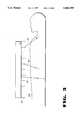
- Septa in existing systemsstart at the imaging crystal of the detector and emanate away from the crystal. Septa can potentially cause degradation of parts of the image, however. In particular, parts of the image may be degraded corresponding to parts of the detectors where the septum is placed. For example, in FIG. 3 ray 220 (non stray) is blocked, even though it is within the field of view. It would be advantageous to mitigate cold spots so as to improve image quality.
- An object of the inventionis to improve image quality of a PET system.
- Another object of the inventionis to provide improved single detector efficiency in a PET scanner.
- Another object of the inventionis to increase the ratio of non-stray radiation to stray radiation detected in a single detector.
- Yet another object of the present inventionis to increase detection of coincidence gamma rays without a corresponding increase in stray radiation detection.
- Another object of the inventionis to help reduce cold spots that may be formed when detectors are rotated about the patient.
- a gamma cameracomprising a detector having a single, continuous scintillator which has an imaging surface, and a first layer of septa.
- the septaare disposed along the imaging surface between the object and the imaging surface.
- the septaare for blocking stray radiation from outside a field of view of the detector.
- a specific embodiment of the gamma camerafurther comprises a gap between the imaging surface and the first layer of septa for allowing non stray radiation to reach the scintillator.
- the detectorhas moving septa.
- FIG. 1illustrates an ideal efficiency curve
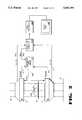
- FIG. 2illustrates a block diagram of a dual head gamma camera system.
- FIG. 3illustrates septa in a gamma camera imaging system.
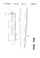
- FIG. 4illustrates detectors with septa and a patient.
- FIG. 5Aillustrates detectors with septa.
- FIG. 5Billustrates a top view of a gamma camera detector having septa.
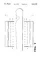
- FIG. 5Cillustrates a cross-sectional view of a gamma camera detector with septa of unequal widths.
- FIG. 5Dillustrates detectors with a plate transparent to gamma rays.
- FIG. 5Eillustrates a portion of a detector with septa in a sandwich construction.
- FIG. 5Fillustrates a septum with a separator.
- FIG. 6Aillustrates radiation detection for a single detector.
- FIG. 6Billustrates radiation detection for a pair of detectors.
- FIG. 7illustrates detectors with two layers of septa.
- FIG. 8Aillustrates a septum with a coating.
- FIG. 8Billustrates the imaging surface with a graded absorber.
- FIG. 9is a transparent view of detectors with septa oriented at an angle from perpendicular to the axis of rotation of the detectors.
- FIG. 10illustrates a detector with moving septa.
- FIG. 2a high level diagram of a dual head detector gamma camera system of the present invention is shown.
- the system of the present inventionincludes a pair of gamma camera detectors 80 and 80' ("dual head") composed of a plurality of photomultiplier tubes, PMTs, arranged in a two dimensional matrix and optically coupled to a glass plate to receive light (e.g., visible photons) from a scintillation crystal 81.
- the PMT arrayconstitutes a photodetector.
- the scintillation crystal 81can be composed of thalium-activated sodium iodine, NaI(Tl).
- the detector pairare shown disposed opposite each other in a 180 degree configuration.
- Gamma rays that strike the scintillation crystal 81cause scintillation events that release a number of visible light photons that are detected by the PMTs with different light intensities.
- Each PMTreports in the form of an analog signal indicative of the amount of light energy detected as a result of the scintillation event. In one embodiment, these signals are digitized at an early circuit stage and are processed digitally.
- the gamma camera detectors 80 and 80'are of the Anger type and can be of a number of well known and commercially available designs.
- An exemplary gamma camera detector used by one embodimentcan contain as many as 55 or 108 PMTs.
- a detector of the paircan also use smaller diameter PMTs along the edges to increase the detector's field of view.
- An embodiment of the present inventionuses forty-nine 76 mm round PMTs and six 51 mm round PMTs for edge filling, however; the number of PMTs, their sizes and their configurations can be varied.
- the detectors 80 and 80'are similarly constructed, such that discussions with respect to one detector are applicable to both.
- the detector pair 80 and 80'are mounted on a gantry 85 which can rotate the detectors 80 and 80' in various orbits (ECT projections) around an object (e.g., a patient) 1020 resting on table 87 (e.g., for ECT scanning operations), thus forming an axis of rotation 1530.
- the detector paircan rotate about a center of rotation through a number of projection angles, as is known in gamma camera technology.
- the gantry 85 and table 87rest on base 89.
- the detector pair 80 and 80'can also be directed transversely across the table 87 (e.g., for total body scanning operations) or placed over the patient 1020 for static imaging.
- signals 1210 and 1212carry initial event detection trigger pulses to a programmable coincidence timing circuit 1050 (CTC).
- CTCprogrammable coincidence timing circuit 1050
- the CTC unit 1050then generates valid event trigger signals over lines 1240 and 1242, respectively, back to the detectors for the 80 and 80'.
- the valid event trigger signals 1240 and 1242are used by the detectors to start (or reset) their accumulators (integrators) which accumulate (integrate) the energy of the detected scintillation and are therefore called "valid event” trigger signals. Integration is not started until a coincidence is detected between detector 80 and 80'. After integration and centroiding, the detectors 80 and 80' output an X, Y, and Z value over lines 1220 and 1222, respectively.
- each detector 80 and 80'contains preamplification and digitization hardware as well as a Digital Event Processor. This hardware can be located within or outside the scintillation detectors 80 and 80'.
- the values transmitted over bus 1220 and bus 1222are input to an acquisition computer system 1055.
- the acquisition computer 1055stores the values for each detected event for each projection angle and this information is routed to an image processor 1060 which contains a standard user interface.
- events associated with various ECT projection anglesare stored in the memory of the computer system in order to generate image information and form count density information.
- This image informationis collected in the form of a matrices for the different ECT projection angles.
- Image matricesare generally collected at different ECT angles and then a reconstruction is done, using tomographic reconstruction to generate a three-dimensional image ("reconstruction") of an organ.
- the image processor 1060also performs image reconstruction, non uniform attenuation correction and uniformity correction based on the acquired event data.
- the image processor 1060is also coupled to a display unit 1065 (which can include a hardcopy device) for visualizing images captured by the camera system.
- This circuitrycan alternatively be located outside the detector heads 80 and 80' or partially spread inside and partially outside of the detector heads 80 and 80'.
- Embodiments of the present inventionmay be used in various gamma camera systems.
- septaare implemented in conjunction with a continuous-detector gamma camera in order to improve the efficiency of the gamma camera.
- FIG. 3a schematic view of a gamma camera having a single, continuous scintillation crystal 81 and septa 250 is shown.
- the septa 250tend to block stray radiation from outside the field of view. For example, ray 230 (stray) is blocked by the septa while ray 210 (non stray) is detected. However, the septa 250 also block some non-stray (desirable) radiation, as illustrated by ray 220.
- FIG. 4illustrates another embodiment, in which a detector 80 comprises a single, continuous scintillation crystal 81.
- the detector 80also comprises a first layer of septa, including a number of individual septa 500 disposed along the imaging surface of the crystal 81 between the object 1020 and the imaging surface.
- the septa 500run substantially perpendicular to the axis of rotation 1530 of the detectors.
- the gap 520allows desirable non stray radiation to pass under the septa 500 to the imaging surface, while stray radiation 590 is blocked by the septa 500. It should be noted, however, that the gap 520 is not required in order to use septa in accordance with the present invention.
- Each of the septa 500is substantially rectangular in shape, and the short axis 1560 of the septum 500 is substantially perpendicular to the imaging surface of the crystal 81. For improved performance the short axis 1560 of the septa 500 may be positioned somewhat off from perpendicular to the imaging surface.
- the septa 500have a thickness of approximately 5 mm.
- the present inventionmay be implemented such that the septa 500 of a given detector 80 do not have equal width (width is the dimension measured in the direction of the short axis 1560) in order to allow more non-stray radiation to reach the crystal.
- widthis the dimension measured in the direction of the short axis 1560
- the present inventionmay be implemented such that the width of a given septum depends upon the location of that septum along the imaging surface.
- the outermost septa 505 of the detector 80have a width W o of approximately 0.5 inches
- the center septum 508(the septum closest to the center axis 1510) has a width W c of approximately 1.6 inches.
- Septa located between the outermost septa 505 and the center septa 508have different widths ranging between W o and W c . Because there is relatively little stray radiation near the edges of the detector 80, this construction may be used to allow more non-stray radiation to reach the crystal than if all septa had widths equal to that of the center septum 508, without significant increasing the stray radiation reaching the crystal.
- the present inventionmay be implemented such that the size of the gap 520 between a given septum and the imaging surface depends upon the location of that septum along the imaging surface. Referring again to FIG. 5C, there is no gap between the outermost septa 505 and the imaging surface, while there is a gap 520 between each of the other septa and the imaging surface. The size of the gap 520 increases for septa closer to the center axis 1510 of the detector, such that the gap 520 is largest at approximately 0.8 inches between the center septum 508 and the imaging surface.
- the detector 80has a thick frame 83 on its outer edge in order to protect the unusable part of the camera.
- the frame 83is 2 inches high and one inch thick.
- a plate 84 transparent to gamma raysmay be placed between the layer of septa 500 and the object 1020.
- septa 500are constructed from lead foil 500 and separated by foam or balsa wood separator material 600, as illustrated in FIG. 5E.
- This configurationis a "sandwich" construction.
- the separator material 600allows radiation to pass while holding the thin septa 500 rigidly.
- FIG. 5Fshows a single layer of the separator material 600 with a single septum 500.
- the thickness of cross-section 640 of the separator 600is from 2 mm to 3.7 mm.
- the thickness of the cross section 540 of the lead foil 500is 0.4 mm.
- a single detector having septa 500 not extending to the imaging surfacehas the tendency to detect radiation in the field of view 2010.
- radiationis detected in the field of view 2020, as illustrated in FIG. 6B. Because of the gap 520, some radiation is detected that would not be detected in a system having septa extending to the imaging surface.
- a systemmay contain multiple layers of septa.
- the systemin addition to the first layer of septa 500, the system contains a second layer of septa 510 located between the first layer 500 and the patient 1020.
- FIG. 7illustrates a system where each detector 80 and 80' has two layers of septa 500 and 510. There are gaps between the layers of septa. Although not shown, additional layers of septa could be added to make a total of three layers, four layers, and so on.
- a septummay be constructed with layers of different materials. As shown in FIG. 8A, the lead layer 900 of the septum is coated with copper layers 900a and 900b. This construction tends to block the weaker stray radiation while allowing the stronger non stray radiation to pass.
- the imaging surface of the crystal 81may be coated with a graded absorber in order to help reduce stray radiation while allowing non stray radiation to pass.
- FIG. 8Bshows a portion of the imaging surface coated with a graded absorber.
- the absorberhas a copper layer 82a on the imaging surface and a lead layer 82b on the copper layer 82a.
- the graded absorberblocks radiation having relatively low energy levels, such as radiation which results from scatter within the patient's body.
- FIG. 9shows a top view of an embodiment of two detectors 80 and 80' with septa 500.
- the lines of the septawill appear to "walk" down different parts of the patient as the detectors 80 and 80' are rotated thus tending to average out the cold spots.
- the septa 500are oriented at an angle 1550, the angle 1550 must not be too large so as to cause the septa 500 to no longer act as a stray radiation shield. Also, too large an angle may cause permanent dark spots in the image of a patient created during rotation.
- the septa 500may be moved in relation to the crystal 81 during the process of detection. As shown in FIG. 10, septa rest on a track 530 that can move the septa 500 in relation to the crystal 81.
- the track 530would be constructed so as to allow radiation to pass through the track itself. It is envisioned that alternative apparatus could be used to move the septa in relation to the crystal 81.
Landscapes
- Health & Medical Sciences (AREA)
- Physics & Mathematics (AREA)
- Life Sciences & Earth Sciences (AREA)
- Medical Informatics (AREA)
- Engineering & Computer Science (AREA)
- High Energy & Nuclear Physics (AREA)
- Nuclear Medicine, Radiotherapy & Molecular Imaging (AREA)
- Optics & Photonics (AREA)
- General Health & Medical Sciences (AREA)
- Biomedical Technology (AREA)
- Molecular Biology (AREA)
- General Physics & Mathematics (AREA)
- Spectroscopy & Molecular Physics (AREA)
- Pathology (AREA)
- Biophysics (AREA)
- Radiology & Medical Imaging (AREA)
- Heart & Thoracic Surgery (AREA)
- Surgery (AREA)
- Animal Behavior & Ethology (AREA)
- Public Health (AREA)
- Veterinary Medicine (AREA)
- Nuclear Medicine (AREA)
Abstract
Description
Claims (36)
Priority Applications (1)
| Application Number | Priority Date | Filing Date | Title |
|---|---|---|---|
| US08/537,008US5602395A (en) | 1995-10-02 | 1995-10-02 | Gamma camera having partial septas and moving septas for positron emission tomography (PET) |
Applications Claiming Priority (1)
| Application Number | Priority Date | Filing Date | Title |
|---|---|---|---|
| US08/537,008US5602395A (en) | 1995-10-02 | 1995-10-02 | Gamma camera having partial septas and moving septas for positron emission tomography (PET) |
Publications (1)
| Publication Number | Publication Date |
|---|---|
| US5602395Atrue US5602395A (en) | 1997-02-11 |
Family
ID=24140797
Family Applications (1)
| Application Number | Title | Priority Date | Filing Date |
|---|---|---|---|
| US08/537,008Expired - LifetimeUS5602395A (en) | 1995-10-02 | 1995-10-02 | Gamma camera having partial septas and moving septas for positron emission tomography (PET) |
Country Status (1)
| Country | Link |
|---|---|
| US (1) | US5602395A (en) |
Cited By (15)
| Publication number | Priority date | Publication date | Assignee | Title |
|---|---|---|---|---|
| US5747812A (en)* | 1995-11-22 | 1998-05-05 | Picker International, Inc. | Scatter filter for emission tomography |
| US5969358A (en)* | 1996-11-26 | 1999-10-19 | Picker International, Inc. | Whole body scan coincidence imaging |
| WO1999054756A1 (en)* | 1998-04-17 | 1999-10-28 | Adac Laboratories | Dual-purpose radiation transmission source for nuclear medicine imaging system |
| US5998792A (en)* | 1998-02-02 | 1999-12-07 | Picker International, Inc. | Positron emission tomography with variable detector geometry |
| US6130430A (en)* | 1997-02-21 | 2000-10-10 | Picker International, Inc. | Septal artifact cancellation in positron emission tomography |
| US6271524B1 (en) | 1998-08-05 | 2001-08-07 | Elgems, Ltd. | Gamma ray collimator |
| US6429432B1 (en)* | 1999-11-26 | 2002-08-06 | Dilon Technologies, Inc. | Gamma radiation isolation shield and method of use |
| US20030111608A1 (en)* | 2000-01-14 | 2003-06-19 | Dulmen Adrianus A. Van | Method of imaging by spect |
| US20040164249A1 (en)* | 2003-02-26 | 2004-08-26 | Crosetto Dario B. | Method and apparatus for determining depth of interactions in a detector for three-dimensional complete body screening |
| US20040195512A1 (en)* | 2000-05-16 | 2004-10-07 | Crosetto Dario B. | Method and apparatus for anatomical and functional medical imaging |
| WO2005071439A1 (en)* | 2004-01-15 | 2005-08-04 | Koninklijke Philips Electronics, N.V. | Asymmetric axial filter for pet imaging systems |
| US20060145081A1 (en)* | 2004-09-27 | 2006-07-06 | Hawman Eric G | Collimator with variable focusing and direction of view for nuclear medicine imaging |
| US7132664B1 (en) | 2002-11-09 | 2006-11-07 | Crosetto Dario B | Method and apparatus for improving PET detectors |
| CN100442081C (en)* | 2003-10-27 | 2008-12-10 | 图片探测系统公司 | PET scanner with structured optics |
| US9606245B1 (en) | 2015-03-24 | 2017-03-28 | The Research Foundation For The State University Of New York | Autonomous gamma, X-ray, and particle detector |
Citations (12)
| Publication number | Priority date | Publication date | Assignee | Title |
|---|---|---|---|---|
| US1874577A (en)* | 1931-07-31 | 1932-08-30 | Westinghouse X Ray Co Inc | Revolving and stationary X-ray screen |
| US2767323A (en)* | 1951-07-21 | 1956-10-16 | Picker X Ray Corp Waite Mfg | X-ray grid actuating device |
| US3955088A (en)* | 1974-10-02 | 1976-05-04 | G. D. Searle & Co. | Positron imaging device with plural coincidence channels and graded radiation absorption |
| US4150292A (en)* | 1977-02-18 | 1979-04-17 | Ter Pogossian Michel M | Imaging device for computerized emission tomography |
| JPS60214288A (en)* | 1984-04-11 | 1985-10-26 | Hitachi Medical Corp | Scintillation camera |
| JPH03115989A (en)* | 1989-09-29 | 1991-05-16 | Hamamatsu Photonics Kk | Positron ct device |
| US5151599A (en)* | 1990-03-12 | 1992-09-29 | Commissariat A L'energie Atomique | Device to display disintegrations of positrons using barycentric and time of flight measurements |
| US5210420A (en)* | 1991-12-19 | 1993-05-11 | Positron Corporation | Positron emission tomography scanner |
| US5224037A (en)* | 1991-03-15 | 1993-06-29 | Cti, Inc. | Design of super-fast three-dimensional projection system for Positron Emission Tomography |
| US5291021A (en)* | 1991-07-01 | 1994-03-01 | Hamamatsu Photonics K.K. | Positron computed tomography scanner |
| US5451789A (en)* | 1993-07-19 | 1995-09-19 | Board Of Regents, The University Of Texas System | High performance positron camera |
| US5512754A (en)* | 1994-11-14 | 1996-04-30 | Summit World Trade Corp. | Filtered collimator for dual isotope medical imaging |
- 1995
- 1995-10-02USUS08/537,008patent/US5602395A/ennot_activeExpired - Lifetime
Patent Citations (12)
| Publication number | Priority date | Publication date | Assignee | Title |
|---|---|---|---|---|
| US1874577A (en)* | 1931-07-31 | 1932-08-30 | Westinghouse X Ray Co Inc | Revolving and stationary X-ray screen |
| US2767323A (en)* | 1951-07-21 | 1956-10-16 | Picker X Ray Corp Waite Mfg | X-ray grid actuating device |
| US3955088A (en)* | 1974-10-02 | 1976-05-04 | G. D. Searle & Co. | Positron imaging device with plural coincidence channels and graded radiation absorption |
| US4150292A (en)* | 1977-02-18 | 1979-04-17 | Ter Pogossian Michel M | Imaging device for computerized emission tomography |
| JPS60214288A (en)* | 1984-04-11 | 1985-10-26 | Hitachi Medical Corp | Scintillation camera |
| JPH03115989A (en)* | 1989-09-29 | 1991-05-16 | Hamamatsu Photonics Kk | Positron ct device |
| US5151599A (en)* | 1990-03-12 | 1992-09-29 | Commissariat A L'energie Atomique | Device to display disintegrations of positrons using barycentric and time of flight measurements |
| US5224037A (en)* | 1991-03-15 | 1993-06-29 | Cti, Inc. | Design of super-fast three-dimensional projection system for Positron Emission Tomography |
| US5291021A (en)* | 1991-07-01 | 1994-03-01 | Hamamatsu Photonics K.K. | Positron computed tomography scanner |
| US5210420A (en)* | 1991-12-19 | 1993-05-11 | Positron Corporation | Positron emission tomography scanner |
| US5451789A (en)* | 1993-07-19 | 1995-09-19 | Board Of Regents, The University Of Texas System | High performance positron camera |
| US5512754A (en)* | 1994-11-14 | 1996-04-30 | Summit World Trade Corp. | Filtered collimator for dual isotope medical imaging |
Non-Patent Citations (8)
| Title |
|---|
| C. J. Thompson, . . . , The Effect of Collimation on Singles Rates in Multi Slice PET, IEEE Transactions on Nuclear Science, vol. 36, No. 1, Feb., 1989, pp. 1072 1077.* |
| C. J. Thompson, . . . , The Effect of Collimation on Singles Rates in Multi-Slice PET, IEEE Transactions on Nuclear Science, vol. 36, No. 1, Feb., 1989, pp. 1072-1077. |
| David Rollo, Nuclear Medicine Physics Instrumentation and Agents, Mosby, St. Louis, (1977), pp. 295 303 no month.* |
| David Rollo, Nuclear Medicine Physics Instrumentation and Agents, Mosby, St. Louis, (1977), pp. 295-303 no month. |
| Dr. Everett W. Stoub, Ph.D., ECAT Scanners Technical Introduction, May, 1987, pp. 1 12, Siemens Gammasonics Inc., Des Plaines, Illinois.* |
| Dr. Everett W. Stoub, Ph.D., ECAT Scanners Technical Introduction, May, 1987, pp. 1-12, Siemens Gammasonics Inc., Des Plaines, Illinois. |
| Siemens Product Brochure, Three Dimensional Positron Emission Tomography ( PET ) ECAT Scanner, pp. 1 18, no date.* |
| Siemens Product Brochure, Three-Dimensional Positron Emission Tomography (PET) ECAT Scanner, pp. 1-18, no date. |
Cited By (22)
| Publication number | Priority date | Publication date | Assignee | Title |
|---|---|---|---|---|
| US5747812A (en)* | 1995-11-22 | 1998-05-05 | Picker International, Inc. | Scatter filter for emission tomography |
| US5969358A (en)* | 1996-11-26 | 1999-10-19 | Picker International, Inc. | Whole body scan coincidence imaging |
| US6130430A (en)* | 1997-02-21 | 2000-10-10 | Picker International, Inc. | Septal artifact cancellation in positron emission tomography |
| EP0863411A3 (en)* | 1997-02-21 | 2001-09-12 | Picker International, Inc. | Positron emission tomography |
| US5998792A (en)* | 1998-02-02 | 1999-12-07 | Picker International, Inc. | Positron emission tomography with variable detector geometry |
| WO1999054756A1 (en)* | 1998-04-17 | 1999-10-28 | Adac Laboratories | Dual-purpose radiation transmission source for nuclear medicine imaging system |
| US6100531A (en)* | 1998-04-17 | 2000-08-08 | Adac Laboratories | Dual-purpose radiation transmission source for nuclear medicine imaging system |
| US6271524B1 (en) | 1998-08-05 | 2001-08-07 | Elgems, Ltd. | Gamma ray collimator |
| US6429432B1 (en)* | 1999-11-26 | 2002-08-06 | Dilon Technologies, Inc. | Gamma radiation isolation shield and method of use |
| US6967331B2 (en)* | 2000-01-14 | 2005-11-22 | Van Dulmen Adrianus A | Method of imaging by spect |
| US20030111608A1 (en)* | 2000-01-14 | 2003-06-19 | Dulmen Adrianus A. Van | Method of imaging by spect |
| US20040195512A1 (en)* | 2000-05-16 | 2004-10-07 | Crosetto Dario B. | Method and apparatus for anatomical and functional medical imaging |
| US7132664B1 (en) | 2002-11-09 | 2006-11-07 | Crosetto Dario B | Method and apparatus for improving PET detectors |
| US20060261279A1 (en)* | 2002-11-09 | 2006-11-23 | Crosetto Dario B | Method and apparatus for improving pet detectors |
| US20040164249A1 (en)* | 2003-02-26 | 2004-08-26 | Crosetto Dario B. | Method and apparatus for determining depth of interactions in a detector for three-dimensional complete body screening |
| CN100442081C (en)* | 2003-10-27 | 2008-12-10 | 图片探测系统公司 | PET scanner with structured optics |
| WO2005071439A1 (en)* | 2004-01-15 | 2005-08-04 | Koninklijke Philips Electronics, N.V. | Asymmetric axial filter for pet imaging systems |
| CN100498380C (en)* | 2004-01-15 | 2009-06-10 | 皇家飞利浦电子股份有限公司 | System and method for radiographic imaging |
| US20060145081A1 (en)* | 2004-09-27 | 2006-07-06 | Hawman Eric G | Collimator with variable focusing and direction of view for nuclear medicine imaging |
| US7345282B2 (en)* | 2004-09-27 | 2008-03-18 | Siemens Medical Solutions Usa, Inc. | Collimator with variable focusing and direction of view for nuclear medicine imaging |
| US9606245B1 (en) | 2015-03-24 | 2017-03-28 | The Research Foundation For The State University Of New York | Autonomous gamma, X-ray, and particle detector |
| US9835737B1 (en) | 2015-03-24 | 2017-12-05 | The Research Foundation For The State University Of New York | Autonomous gamma, X-ray, and particle detector |
Similar Documents
| Publication | Publication Date | Title |
|---|---|---|
| US5760401A (en) | Resolution enhancement apparatus and method for dual head gamma camera system capable of coincidence imaging | |
| US5602395A (en) | Gamma camera having partial septas and moving septas for positron emission tomography (PET) | |
| CA2252993C (en) | Detector assembly for multi-modality scanners | |
| US8884239B2 (en) | High resolution medical imaging detector | |
| Kanno et al. | HEADTOME: a hybrid emission tomograph for single photon and positron emission imaging of the brain | |
| Patton et al. | Coincidence imaging with a dual-head scintillation camera | |
| US8481947B2 (en) | Method and system for nuclear imaging using multi-zone detector architecture | |
| US20100282972A1 (en) | Indirect radiation detector | |
| US6303935B1 (en) | Combination PET/SPECT nuclear imaging system | |
| IL137821A (en) | Spect gamma camera | |
| Hamill et al. | Scatter reduction with energy-weighted acquisition | |
| US5751000A (en) | Prefilter collimator for PET gamma camera | |
| US6881960B2 (en) | Thick scintillation plate with internal light collimation | |
| US20090272904A1 (en) | Small Field of View Detector Head ("Spect") Attenuation Correction System | |
| Del Guerra et al. | An integrated PET-SPECT small animal imager: preliminary results | |
| US8809790B2 (en) | Method and system for nuclear imaging using multi-zone detector architecture | |
| EP0892284B1 (en) | Method and apparatus for diagnostic imaging | |
| US6140649A (en) | Imaging attenuation correction employing simultaneous transmission/emission scanning | |
| EP0877956B1 (en) | Scatter filter for emission tomography | |
| US9612344B2 (en) | Positron emission tomography and single photon emission computed tomography based on intensity attenuation shadowing methods and effects | |
| WO1997008569A1 (en) | An imaging apparatus | |
| US20050029461A1 (en) | Gamma camera using rotating scintillation bar detector and method for tomographic imaging using the same | |
| Bartzakos et al. | A PET detector with depth-of-interaction determination | |
| US6384416B1 (en) | Transmission scanning technique for gamma-camera coincidence imaging | |
| US20040159791A1 (en) | Pet/spect nuclear scanner |
Legal Events
| Date | Code | Title | Description |
|---|---|---|---|
| AS | Assignment | Owner name:ADAC LABORATORIES, INC., CALIFORNIA Free format text:ASSIGNMENT OF ASSIGNORS INTEREST;ASSIGNORS:NELLEMANN, PETER;HINES, HORACE H.;MUEHLLEHNER, GERD;AND OTHERS;REEL/FRAME:007716/0870;SIGNING DATES FROM 19950928 TO 19950929 | |
| AS | Assignment | Owner name:ABN AMRO BANK N.V., AS AGENT, CALIFORNIA Free format text:SECURITY INTEREST;ASSIGNOR:ADAC LABORATORIES;REEL/FRAME:008213/0558 Effective date:19960731 Owner name:ABN AMRO BANK N.V., AS AGENT, CALIFORNIA Free format text:SECURITY INTEREST;ASSIGNOR:ADAC LABORATORIES;REEL/FRAME:008213/0471 Effective date:19960731 | |
| STCF | Information on status: patent grant | Free format text:PATENTED CASE | |
| AS | Assignment | Owner name:ABN AMRO BANK N.V., AS AGENT, CALIFORNIA Free format text:SECURITY INTEREST;ASSIGNOR:ADAC LABORATORIES;REEL/FRAME:010371/0217 Effective date:19991013 | |
| FEPP | Fee payment procedure | Free format text:PAYOR NUMBER ASSIGNED (ORIGINAL EVENT CODE: ASPN); ENTITY STATUS OF PATENT OWNER: LARGE ENTITY | |
| FPAY | Fee payment | Year of fee payment:4 | |
| FEPP | Fee payment procedure | Free format text:PAYER NUMBER DE-ASSIGNED (ORIGINAL EVENT CODE: RMPN); ENTITY STATUS OF PATENT OWNER: LARGE ENTITY Free format text:PAYOR NUMBER ASSIGNED (ORIGINAL EVENT CODE: ASPN); ENTITY STATUS OF PATENT OWNER: LARGE ENTITY | |
| AS | Assignment | Owner name:ADAC LABORATORIES, CALIFORNIA Free format text:RELEASE;ASSIGNOR:ABN AMRO BANK N.V., AS AGENT;REEL/FRAME:011506/0729 Effective date:20010131 | |
| AS | Assignment | Owner name:KONINKLIJKE PHILIPS ELECTRONICS N.V., NETHERLANDS Free format text:ASSIGNMENT OF ASSIGNORS INTEREST;ASSIGNOR:ADAC LABORATORIES;REEL/FRAME:013475/0446 Effective date:20020819 | |
| FPAY | Fee payment | Year of fee payment:8 | |
| FPAY | Fee payment | Year of fee payment:12 |