US5601711A - Selective separation filter device - Google Patents
Selective separation filter deviceDownload PDFInfo
- Publication number
- US5601711A US5601711AUS08/331,974US33197494AUS5601711AUS 5601711 AUS5601711 AUS 5601711AUS 33197494 AUS33197494 AUS 33197494AUS 5601711 AUS5601711 AUS 5601711A
- Authority
- US
- United States
- Prior art keywords
- module
- outlet end
- sample reservoir
- coupling member
- inlet end
- Prior art date
- Legal status (The legal status is an assumption and is not a legal conclusion. Google has not performed a legal analysis and makes no representation as to the accuracy of the status listed.)
- Expired - Lifetime
Links
- 238000000926separation methodMethods0.000titleclaimsabstractdescription17
- 239000012530fluidSubstances0.000claimsabstractdescription63
- 238000001914filtrationMethods0.000claimsabstractdescription17
- 239000000463materialSubstances0.000claimsabstractdescription13
- 238000011084recoveryMethods0.000claimsdescription25
- 230000008878couplingEffects0.000claims14
- 238000010168coupling processMethods0.000claims14
- 238000005859coupling reactionMethods0.000claims14
- 239000012465retentateSubstances0.000abstractdescription29
- 239000000706filtrateSubstances0.000abstractdescription10
- 238000005119centrifugationMethods0.000abstractdescription8
- 230000006835compressionEffects0.000abstractdescription8
- 238000007906compressionMethods0.000abstractdescription8
- 239000012620biological materialSubstances0.000abstractdescription6
- 230000000295complement effectEffects0.000abstractdescription5
- 230000005484gravityEffects0.000abstractdescription3
- 238000000034methodMethods0.000description19
- 239000012528membraneSubstances0.000description18
- 102000004169proteins and genesHuman genes0.000description17
- 108090000623proteins and genesProteins0.000description17
- 239000010410layerSubstances0.000description14
- 210000004027cellAnatomy0.000description10
- 230000002441reversible effectEffects0.000description6
- 230000000717retained effectEffects0.000description5
- 238000000108ultra-filtrationMethods0.000description5
- 238000007789sealingMethods0.000description4
- 238000011010flushing procedureMethods0.000description3
- 238000003306harvestingMethods0.000description3
- 239000000203mixtureSubstances0.000description3
- 238000001742protein purificationMethods0.000description3
- 210000002421cell wallAnatomy0.000description2
- 230000002209hydrophobic effectEffects0.000description2
- 235000015097nutrientsNutrition0.000description2
- 239000011148porous materialSubstances0.000description2
- 238000000746purificationMethods0.000description2
- 239000000126substanceSubstances0.000description2
- 239000000853adhesiveSubstances0.000description1
- 230000001070adhesive effectEffects0.000description1
- 230000000994depressogenic effectEffects0.000description1
- 239000012634fragmentSubstances0.000description1
- 238000003780insertionMethods0.000description1
- 230000037431insertionEffects0.000description1
- 230000003993interactionEffects0.000description1
- 238000004519manufacturing processMethods0.000description1
- 239000012982microporous membraneSubstances0.000description1
- 238000000465mouldingMethods0.000description1
- 230000002093peripheral effectEffects0.000description1
- 238000011045prefiltrationMethods0.000description1
- 239000000047productSubstances0.000description1
- 239000002356single layerSubstances0.000description1
Images


Classifications
- B—PERFORMING OPERATIONS; TRANSPORTING
- B01—PHYSICAL OR CHEMICAL PROCESSES OR APPARATUS IN GENERAL
- B01D—SEPARATION
- B01D61/00—Processes of separation using semi-permeable membranes, e.g. dialysis, osmosis or ultrafiltration; Apparatus, accessories or auxiliary operations specially adapted therefor
- B01D61/14—Ultrafiltration; Microfiltration
- B01D61/18—Apparatus therefor
- B—PERFORMING OPERATIONS; TRANSPORTING
- B01—PHYSICAL OR CHEMICAL PROCESSES OR APPARATUS IN GENERAL
- B01D—SEPARATION
- B01D21/00—Separation of suspended solid particles from liquids by sedimentation
- B01D21/26—Separation of sediment aided by centrifugal force or centripetal force
- B01D21/262—Separation of sediment aided by centrifugal force or centripetal force by using a centrifuge
- B—PERFORMING OPERATIONS; TRANSPORTING
- B01—PHYSICAL OR CHEMICAL PROCESSES OR APPARATUS IN GENERAL
- B01D—SEPARATION
- B01D25/00—Filters formed by clamping together several filtering elements or parts of such elements
- B01D25/02—Filters formed by clamping together several filtering elements or parts of such elements in which the elements are pre-formed independent filtering units, e.g. modular systems
- B—PERFORMING OPERATIONS; TRANSPORTING
- B01—PHYSICAL OR CHEMICAL PROCESSES OR APPARATUS IN GENERAL
- B01D—SEPARATION
- B01D29/00—Filters with filtering elements stationary during filtration, e.g. pressure or suction filters, not covered by groups B01D24/00 - B01D27/00; Filtering elements therefor
- B01D29/01—Filters with filtering elements stationary during filtration, e.g. pressure or suction filters, not covered by groups B01D24/00 - B01D27/00; Filtering elements therefor with flat filtering elements
- B01D29/05—Filters with filtering elements stationary during filtration, e.g. pressure or suction filters, not covered by groups B01D24/00 - B01D27/00; Filtering elements therefor with flat filtering elements supported
- B—PERFORMING OPERATIONS; TRANSPORTING
- B01—PHYSICAL OR CHEMICAL PROCESSES OR APPARATUS IN GENERAL
- B01D—SEPARATION
- B01D29/00—Filters with filtering elements stationary during filtration, e.g. pressure or suction filters, not covered by groups B01D24/00 - B01D27/00; Filtering elements therefor
- B01D29/50—Filters with filtering elements stationary during filtration, e.g. pressure or suction filters, not covered by groups B01D24/00 - B01D27/00; Filtering elements therefor with multiple filtering elements, characterised by their mutual disposition
- B01D29/56—Filters with filtering elements stationary during filtration, e.g. pressure or suction filters, not covered by groups B01D24/00 - B01D27/00; Filtering elements therefor with multiple filtering elements, characterised by their mutual disposition in series connection
- B01D29/58—Filters with filtering elements stationary during filtration, e.g. pressure or suction filters, not covered by groups B01D24/00 - B01D27/00; Filtering elements therefor with multiple filtering elements, characterised by their mutual disposition in series connection arranged concentrically or coaxially
- B—PERFORMING OPERATIONS; TRANSPORTING
- B01—PHYSICAL OR CHEMICAL PROCESSES OR APPARATUS IN GENERAL
- B01D—SEPARATION
- B01D2221/00—Applications of separation devices
- B01D2221/10—Separation devices for use in medical, pharmaceutical or laboratory applications, e.g. separating amalgam from dental treatment residues
Definitions
- This inventionconcerns filter apparatus for selective separation of materials, especially fluid materials such as biological materials or biomolecules from a fluid sample, under a force such as centrifugation, positive pressure, vacuum, or gravity.
- Filter apparatusare known for selectively separating and binding biomolecules contained in a solution; see, for example, U.S. Pat. No. 5,124,041.
- a binding support membrane in contact with a cut-off filter membraneis used for binding the biomolecules such that the solution will pass through the binding support before passing through the cut-off membrane.
- the media layersare loose and not mounted in a support structure with the results that their handling is more difficult than if they were each mounted in a separate support.
- the devicealso lacks the capacity in operation to clean the sample in-line prior to the binding layer.
- Dead end filtersare cylindrical housings with filter media permanently sealed at the bottom.
- the housingfits into the top of a centrifuge tube, and the fluid sample is placed in the housing and spun through the filter into the tube.
- These deviceshave the disadvantage that only the filtrate is easily recoverable (not the retentate) and they have only one filtration layer.
- Reverse flow devicesare centrifugation devices in which the flow of filtrate is counter to the direction of the centrifuge force. See, for example, U.S. Pat. No. 4,522,713. They typically consist of a plunger inside a centrifuge tube. The plunger has filter media sealed on its bottom face. In use, a fluid sample and then the plunger are placed in the centrifuge tube. With the plunger in place, the level of the fluid around the plunger is higher than the level within it. Under the force of centrifugation, the fluid seeks to equalize the level forcing some through the filter. These devices have disadvantages in that they do not completely filter a sample (some unfiltered fluid remains outside the plunger), they are usually single layer devices, and they cannot clean the sample prior to separation.
- the inventioncomprises a filter apparatus for selective separation of materials, such as biomaterials, from a fluid sample under a force such as centrifugation, positive pressure, vacuum, or gravity.
- the apparatuscomprises two or more tubular elements that can be assembled together as a train of elements in axial alignment.
- the assemblyforms a leak-proof conduit for the passage of the fluid sample.
- the elementscomprise a) one or more modules, each such module housing a filter media and having open ends and b) a sample reservoir to hold the sample volume and having open ends.
- the periphery of the open ends of the elementsis configured as connection structures such that they can be assembled and disassembled to form the leak-proof conduit.
- connection structuresmay include, for example, elastomeric seal (e.g., O-ring), threads, Luer fittings, compression fittings, bayonet fittings, snap fittings, or other suitable connection.
- Each media housinghas one or more layers of filter media mounted by a peripheral seal in the interior of the module in such a way that fluid can pass through (without fluid bypass) from one open end of the module to the other open end only by passing through the respective media layers. Examples of commonly known manufacturing processes that may be used to achieve this seal include thermal staking, ultrasonic staking, adhesives, mechanical pinch, insert molding, or any other seal-forming means.
- the inventioncomprises a family of interchangeable modules. Sealed into each module is one or more layers of filter media.
- filter mediainclude screens, depth filters, microporous membranes, ultrafiltration membranes (also called cut-off membranes or molecular weight cut-off membranes), and binding media.
- Binding mediasuch as protein binding membranes typically have pore size in the microporous range but have some affinity for proteins (such as electrostatic, ionic, chemical, ligand-receptor, or hydrophobic).
- the end usermay also disassemble the apparatus. This feature allows the user to recover either the material that is retained on the media (retentate) or the fluid that has passed through the media (filtrate) from each module.
- the modular nature of the apparatusalso allows the modules to be reversed, either directly or by the use of adapter elements. Reversing a module after an initial filtration step and reapplying the driving force to the system allows the user to remove and recover retentate from the module. Traditional methods such as pipetting, rinsing, etc., may be used alternatively to recover retentate.
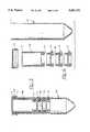
- FIG. 1is a top view of a filter media module comprising a circular filter media shown as a filter fragment;
- FIG. 2is a bottom view of a filter media module:
- FIG. 3is a side view in diametral section of a filter media module taken on line 3--3 of FIG. 1;
- FIG. 4is a side view of a filter media module:
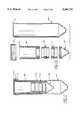
- FIG. 5is an elevational view in section of assembled elements of a filter apparatus for selective separation of materials in a centrifuge tube configuration
- FIG. 6is an exploded view in elevation and in section showing the same elements
- FIG. 7is an elevational view in section of assembled elements with the filter media module in reversed orientation for recovery of retentate in a centrifuge tube configuration
- FIG. 8is an exploded view in elevation and in section showing the same elements
- FIG. 9is an elevational view in section of assembled elements of a filter apparatus for selective separation of materials in a manifold (negative pressure) configuration
- FIG. 10is an exploded view in elevation and in section showing the same elements
- FIG. 11is an elevational view in section of assembled elements of a filter apparatus for selective separation of materials in a syringe filter (positive pressure) configuration;
- FIG. 12is an exploded view in elevation and in section showing the same elements
- FIG. 13is a side view in diametral section of a train of filter media modules and a sample reservoir having snap lock connections with compression fittings, assembled and inserted in a centrifuge tube, for selective separation of materials;
- FIG. 14is an exploded view of the same elements
- FIG. 15is a side view in diametral section of assembled elements including a reversing adapter and a recovery cup having snap lock connection, inserted in a centrifuge tube, for rinsing and recovery of retentate;
- FIG. 16is an exploded view of the same elements of FIG. 15;
- FIG. 17is an exploded view in perspective of a selective separation device comprising as elements a sample reservoir, a reversible filter media module, and a recovery cup, each of which elements when assembled together has for connection a bayonet lock with compression fittings, shown in centrifuge tube insert configuration; and
- FIG. 18is an elevational view in diametral section of assembled elements including threaded and O-ring connection structures.
- the inventionconcerns an apparatus of the kind described for selective separation of biomaterials from a fluid sample.
- the inventioncomprises a train of open-end tubular elements that are connectable together end-to-end in axial alignment to form a unitary conduit structure defining a flow path for leak-proof passage of the fluid sample through the conduit.
- the elementscomprise one or more filter media modules and a sample reservoir.
- Each media modulehas an inlet, an outlet, and houses one or more layers of filter media.
- the diameter of each moduleis such that it fits, with small clearance, inside a standard centrifuge tube.
- the inlet and outlet of each moduleare configured as connection structures.
- the connection structuresare means by which the modules can be attached to and detached from other modules, the sample reservoir, or other auxiliary elements.
- connection structuresallow the elements to be connected together in a train to allow leak-proof passage of a fluid sample through the filter media of the train.
- connection structuresinclude elastomeric seal (O-ring), threads, Luer lock and Luer slip fittings, compression fittings, snap fittings, bayonet fittings, and like fittings.
- the media housed in each modulemay be one or more layers of screen or depth filter, microporous filter, affinity binding filter, or ultrafiltration filter.
- the sample reservoirhas an inlet, a body portion, and an outlet. The outlet and body portion of the sample reservoir fit, with small clearance, into the interior of a standard centrifuge tube.
- the outlet of the sample reservoiris configured as a connection structure, defined above.
- the inletis configured with a flange that is sized such that the flange rests on the lip on the open end of the centrifuge tube when the sample reservoir is inserted into the centrifuge tube.
- the flangemay include a groove or gap to permit air to pass from the bottom of the centrifuge tube, through the small clearance area between the tube and the elements, through the gap or groove, and into the body of the sample reservoir.
- the inventionadditionally comprises a recovery cup and, optionally, a reversing adapter.
- the recovery cuphas an open end, configured as a connection structure such that it can be attached to the inlet of a filter media module, and a closed end. Fluid passes in through the open end and is retained in the body of the cup.
- the reversing adapterhas two open ends, configured as connection structures such that one end can be attached to the outlet of a filter media module and the other attached to the outlet of the sample reservoir, resulting in the module being assembled in the train in a reversed position.
- Thisis an optional clement because some connection structures allow the direct connection of the sample reservoir outlet to the filter media module outlet (e.g., a bayonet fitting).
- the additional element or elementsassist in recovery of the retentate from a filter media module after initial filtration by allowing the module to be reversed from its original orientation and the driving force reapplied, driving the retentate from the module into the recovery cup.
- the filling open end of the sample reservoiris configured for attachment to a positive pressure source, such as a syringe or pump.
- a positive pressure sourcesuch as a syringe or pump.
- the positive pressureprovides the driving force of filtration.
- This embodimentmay optionally include an outlet element, for connection to downstream tubing or devices, and a reversing adapter element as described above.
- the elementscomprise one or more filter media modules, sample reservoir and an outlet element.
- the outlet elementhas one open end configured for attachment to a vacuum source, such as a vacuum pump or a syringe.
- the other open end of the outletis configured with a connection structure, defined above, for connection to a filter media module.
- the inventionin a further preferred aspect concerns a method for harvesting particulates from a fluid sample, e.g., a sample containing culture cells in nutrient media.
- the methodcomprises the steps of: filling the fluid sample into a sample reservoir connected together in a train of centrifugible tubular elements having complementary connection structures in unitary leak-proof conduit structure relation comprising a filter media module housing a macroporous filter media; centrifuging the fluid sample such that the sample is filtered and the cells are retained on the macroporous filter.
- the inventionfurther comprises disassembling the filter media module bearing the retentate, connecting an inverted recovery cup to cover the retentate module; inverting the cup-module assembly and connecting the assembly to an adapter; connecting the adapter to a sample reservoir; optionally adding a small amount of fluid to the sample reservoir to assist in flushing the retentate off the media, inserting the resulting train of elements into a centrifuge tube; centrifuging the container after capping the tube (e.g., as the elements are shown in FIG. 7); and recovering the thus harvested cells.
- recovery of the particulatescan be done by pipetting or rinsing the retentate from the filter media.
- Still another preferred embodimentconcerns a method for purification of biomaterials from a fluid sample.
- the methodcomprises the steps of: filling the fluid sample into a sample reservoir connected together in a train of centrifugible tubular elements having complementary connection structures in unitary leak-proof conduit structure relation comprising one or more filter media modules, each such module housing filter media, one element comprising a module housing an ultrafiltration filter media; inserting the train of elements into a centrifuge tube; centrifuging the fluid sample such that retentate is obtained on the ultrafiltration filter media; removing the train from the centrifuge tube; and recovering the retentate, preferably employing an adapter and a recovery cup each comprising complementary connection structures.
- Recovery of the retentatein a preferred embodiment comprises the steps of disassembling the module housing the retentate bearing ultrafiltration filter media; connecting the recovery cup to the retentate bearing module; inverting the cup-module assembly and connecting the assembly to an adapter; connecting the adapter to a sample reservoir; optionally adding a small amount of fluid into the sample reservoir to assist in flushing; inserting the resulting train of elements with added fluid into a centrifuge tube; centrifuging the container after capping the tube; and recovering the thus purified retentate.
- recoverycan be done by pipetting or rinsing the retentate from the filter.
- the inventioncomprises a method for selective binding of biomaterials from a fluid sample as described hereinbelow, comprising the steps of: filling the fluid sample into a train of centrifugible tubular elements connected together, one element comprising a module housing a protein binding filter media; inserting the train into a centrifuge tube; centrifuging the fluid sample such that the proteins of interest are bound to the filter media.
- Recovery of the retentatecomprises the additional steps of filling the sample reservoir with a rinsing fluid and centrifuging it through the train to remove non-bound or weakly bound proteins from the filter media, placing the train in a clean centrifuge tube, filling the sample reservoir with an eluting solution (e.g., extreme ionic strength or pH), centrifuging the eluting solution through the media to release the proteins from their bound state.
- eluting solutione.g., extreme ionic strength or pH
- This inventionis illustrated by the following exemplary protocols for protein purification, cell harvesting, and protein binding:
- a leak-proof filter trainby connecting together (using uniformly connectable connection structures) one or more filter media modules (e.g., one containing a macroporous screen or depth media, one a microporous membrane, and one a molecular weight cut-off (MWCO) membrane) and a sample reservoir. Place the assembly into a 50 mL centrifuge tube.
- one or more filter media modulese.g., one containing a macroporous screen or depth media, one a microporous membrane, and one a molecular weight cut-off (MWCO) membrane
- the procedureis identical to that for protein purification except that cells are not lysed and only a single filter module (for a macroporous membrane) is used.
- the captured cellsare recovered in a like manner using a pipette, rinsing the filter, or the invert and spin procedure.
- Binding membranestypically have pore size in the microporous range but have some affinity for proteins (such as electrostatic, ionic, chemical, ligand-receptor, or hydrophobic).
- the binding membranes selected for use in the present methodwill typically be those with a reversible binding interaction.
- the procedure for their useis identical to steps 1-5 of the purification protocol described above except a binding membrane is used in place of the ordinary microporous layer, and it is this layer that retains the proteins of interest.
- the recovery stepinvolves an additional procedure to release the proteins from their bound state.
- the devicein a preferred embodiment can also be used to remove a specific, undesired protein from a sample without the need to release the protein from the bound state.
- the apparatus and method of the inventionhave many advantages.
- the methodis flexible.
- the usercan assemble a train of membranes customized to the requirements of each application.
- the components of the sample volumecan be recovered readily.
- the usercan recover the retentate from any layer by simply disassembling the specific filter module containing that layer from the assembly and using the invert-and-spin procedure with rinse fluid to remove the retentate from the module.
- the filtratemay also be recovered.
- the multilayer designallows the sample to be cleaned and separated in a single step, eliminating the time and equipment required for a pre-filter step.
- the deviceis unique in that it enables the user to select and combine macroporous, microporous, and molecular weight cut-off (MWCO) membranes in a single device.
- MWCOmolecular weight cut-off
- FIGS. 1-4show different views of a preferred embodiment of a filter media module 12 according to the invention.
- the moduleis a shallow tube or conduit for axial passage of fluid through the filter media 14.
- the side wall 16 of the moduleforms an open chamber above the filter media 14.
- the filter mediain turn is supported by a patterned grid 24 (FIG. 1) of upward protruding support bodies 24a separated by depressed annular and radial drain channels 20a, 20b leading to through passage channels 28 which provide drainage outlets for fluid sample filtrate passing through the filter media 14 and for reverse flow of rinse fluid for purposes of rinsing.
- the module 12f or complementary threaded connectioncomprises an external thread 34 and an internal thread 36.
- a female sealing surface 30 and a male sealing surface 32are provided in each module such that connection together of the adjacent modules serves to press these respective surfaces intimately and pervasively together in matching leak-proof relation. Threading can be reversed (i.e., to achieve unthreading) as desired to accommodate various purposes, as described herein.
- the periphery of one open end of the module 12is formed with scalloped knurls 12a to facilitate threading and unthreading of the module by rotary finger pressure at that open end.
- the filter media 14 sealed at its outer edge on the seal area 26is supported and spaced by these bodies 24a above the drain channels 20a ,20b so that filtrate fluid can pass through the filter media and drain centrally along the drain channels and then enter and pass through the through passage channels 28 to a container in a centrifuge insert, manifold or syringe insert configuration.
- these elementsadvantageously provide for reverse fluid flow, e.g., rinse fluid, through the channels 28, 20a, 20b and through the filter media 14 for purposes of rinsing or retentate recovery in a centrifuge insert, manifold or syringe configuration.
- FIGS. 5 and 6show a preferred embodiment of the invention configured as a centrifuge tube insert.
- the elementsare shown with threaded connection structures.
- the elements in this examplecomprise three filter media modules 12, and a sample reservoir 48.
- the apparatusis assembled by threading together the modules and the reservoir. Threading the elements brings the male and female sealing surfaces 30 and 32 into contact and forms a leak-proof seal.
- the assemblyis inserted into a centrifuge tube 40 so that the flange 2 of the reservoir rests on the lip 3 of the tube.
- the reservoiris filled with the sample fluid, a cap 50 is placed on the tube, and the assembly is spun in a centrifuge. The assembly is then disassembled and the retentate on each module or the filtrate is recovered.
- FIG. 7 and 8show a preferred embodiment for recovery of retentate from a filter media module 12.
- a recovery cup 42is threaded onto the inlet on the module, a reversing adapter 46 is threaded to the module outlet, the assembly inverted, threaded to the sample reservoir 48, and inserted into a centrifuge tube 40.
- a small amount of fluidis added to the reservoir to assist in flushing the module, the cap 50 assembled, and the assembly is spun gently to drive the retentate into the cup.
- a preferred embodimentcomprises selective separation apparatus in a manifold configuration, (preferred, e.g., for use with a vacuum manifold) having threaded connection structures comprising external and internal threads 34, 36, including an outlet funnel structure 58 having a funnel stem removably supported in a vacuum manifold stopper 6.
- a preferred embodimentcomprises a selective separation apparatus in a syringe filter configuration having threaded connection structures.
- the sample reservoir 48takes the form of an inlet element with the open filling end configured with a female Luer lock fitting 4f or attachment to a syringe or other positive pressure device.
- An outlet element 62is shown with a male slip Luer fitting 5 for optional connection to a downstream device or tubing.
- a preferred embodimentcomprises apparatus in a centrifuge insert configuration having a snap lock connection means comprising outer and inner snap locks 34a, 36a which are used and are a leak-proof functional equivalent of the thread connection means of the herein described thread-connected apparatus.
- a preferred embodimentcomprises selective separation apparatus in a centrifuge insert configuration having a bayonet lock connection means with compression fittings, including a sample reservoir 48 with opposed bayonet insert channels 34c, opposed bayonet slide channels 34d, a reversible filter media module 12 with opposed bayonet locks 12b and a recovery cup 42 with opposed bayonet locks 12b.
- a train of one or more filter modules 12are assembled in the sample reservoir 48 by inserting the modules, one at a time, such that the opposed pair of bayonet locks 12b coincide with the insert channels 34c and further such that each pair of locks 12 reaches the channel end and is rotated fully into the innermost lock channel 34d to achieve a compression fit, after which the insertion and locking procedure is repeated with the next module 12.
- the apparatusis ready for centrifugation with a sample fluid and is carried out by the selective separation procedure described above for collection and processing of retentate and filtrate material resulting from filtration. In this configuration, the recovery cup and the module can be inverted and directly attached to the reservoir, without the need for an adapter.
- FIG. 18shows filter media modules 12 connected together by threads 34, 36 in combination with an elastomeric seal 7 (e.g., an O-ring or equivalent seal) preferably under fluid-tight compression.
- an elastomeric seal 7e.g., an O-ring or equivalent seal
Landscapes
- Chemical & Material Sciences (AREA)
- Chemical Kinetics & Catalysis (AREA)
- Engineering & Computer Science (AREA)
- Water Supply & Treatment (AREA)
- Centrifugal Separators (AREA)
Abstract
Description
This invention concerns filter apparatus for selective separation of materials, especially fluid materials such as biological materials or biomolecules from a fluid sample, under a force such as centrifugation, positive pressure, vacuum, or gravity.
Filter apparatus are known for selectively separating and binding biomolecules contained in a solution; see, for example, U.S. Pat. No. 5,124,041. In a preferred method, a binding support membrane in contact with a cut-off filter membrane is used for binding the biomolecules such that the solution will pass through the binding support before passing through the cut-off membrane. However, the media layers are loose and not mounted in a support structure with the results that their handling is more difficult than if they were each mounted in a separate support. The device also lacks the capacity in operation to clean the sample in-line prior to the binding layer.
Dead end filters, commonly available from many sources, are cylindrical housings with filter media permanently sealed at the bottom. The housing fits into the top of a centrifuge tube, and the fluid sample is placed in the housing and spun through the filter into the tube. These devices have the disadvantage that only the filtrate is easily recoverable (not the retentate) and they have only one filtration layer.
Reverse flow devices are centrifugation devices in which the flow of filtrate is counter to the direction of the centrifuge force. See, for example, U.S. Pat. No. 4,522,713. They typically consist of a plunger inside a centrifuge tube. The plunger has filter media sealed on its bottom face. In use, a fluid sample and then the plunger are placed in the centrifuge tube. With the plunger in place, the level of the fluid around the plunger is higher than the level within it. Under the force of centrifugation, the fluid seeks to equalize the level forcing some through the filter. These devices have disadvantages in that they do not completely filter a sample (some unfiltered fluid remains outside the plunger), they are usually single layer devices, and they cannot clean the sample prior to separation.
The invention comprises a filter apparatus for selective separation of materials, such as biomaterials, from a fluid sample under a force such as centrifugation, positive pressure, vacuum, or gravity. The apparatus comprises two or more tubular elements that can be assembled together as a train of elements in axial alignment. The assembly forms a leak-proof conduit for the passage of the fluid sample. The elements comprise a) one or more modules, each such module housing a filter media and having open ends and b) a sample reservoir to hold the sample volume and having open ends. The periphery of the open ends of the elements is configured as connection structures such that they can be assembled and disassembled to form the leak-proof conduit. Such connection structures may include, for example, elastomeric seal (e.g., O-ring), threads, Luer fittings, compression fittings, bayonet fittings, snap fittings, or other suitable connection. Each media housing has one or more layers of filter media mounted by a peripheral seal in the interior of the module in such a way that fluid can pass through (without fluid bypass) from one open end of the module to the other open end only by passing through the respective media layers. Examples of commonly known manufacturing processes that may be used to achieve this seal include thermal staking, ultrasonic staking, adhesives, mechanical pinch, insert molding, or any other seal-forming means.
The invention comprises a family of interchangeable modules. Sealed into each module is one or more layers of filter media. Examples of commercially available filter media include screens, depth filters, microporous membranes, ultrafiltration membranes (also called cut-off membranes or molecular weight cut-off membranes), and binding media. Binding media such as protein binding membranes typically have pore size in the microporous range but have some affinity for proteins (such as electrostatic, ionic, chemical, ligand-receptor, or hydrophobic). With a relatively small set of modules housing different media, a large number of configurations can be assembled by the manufacturer or by the end user to suit a wide range of applications. Examples of several configurations are included in the following description of the preferred embodiments and in the exemplary protocols.
The end user may also disassemble the apparatus. This feature allows the user to recover either the material that is retained on the media (retentate) or the fluid that has passed through the media (filtrate) from each module. The modular nature of the apparatus also allows the modules to be reversed, either directly or by the use of adapter elements. Reversing a module after an initial filtration step and reapplying the driving force to the system allows the user to remove and recover retentate from the module. Traditional methods such as pipetting, rinsing, etc., may be used alternatively to recover retentate.
The features and advantages of the filter apparatus according to the invention will be seen by reference to the following detailed description in connection with the accompanying drawings in which:
FIG. 1 is a top view of a filter media module comprising a circular filter media shown as a filter fragment;
FIG. 2 is a bottom view of a filter media module:
FIG. 3 is a side view in diametral section of a filter media module taken online 3--3 of FIG. 1;
FIG. 4 is a side view of a filter media module:
FIG. 5 is an elevational view in section of assembled elements of a filter apparatus for selective separation of materials in a centrifuge tube configuration;
FIG. 6 is an exploded view in elevation and in section showing the same elements;
FIG. 7 is an elevational view in section of assembled elements with the filter media module in reversed orientation for recovery of retentate in a centrifuge tube configuration;
FIG. 8 is an exploded view in elevation and in section showing the same elements;
FIG. 9 is an elevational view in section of assembled elements of a filter apparatus for selective separation of materials in a manifold (negative pressure) configuration;
FIG. 10 is an exploded view in elevation and in section showing the same elements;
FIG. 11 is an elevational view in section of assembled elements of a filter apparatus for selective separation of materials in a syringe filter (positive pressure) configuration;
FIG. 12 is an exploded view in elevation and in section showing the same elements;
FIG. 13 is a side view in diametral section of a train of filter media modules and a sample reservoir having snap lock connections with compression fittings, assembled and inserted in a centrifuge tube, for selective separation of materials;
FIG. 14 is an exploded view of the same elements;
FIG. 15 is a side view in diametral section of assembled elements including a reversing adapter and a recovery cup having snap lock connection, inserted in a centrifuge tube, for rinsing and recovery of retentate;
FIG. 16 is an exploded view of the same elements of FIG. 15;
FIG. 17 is an exploded view in perspective of a selective separation device comprising as elements a sample reservoir, a reversible filter media module, and a recovery cup, each of which elements when assembled together has for connection a bayonet lock with compression fittings, shown in centrifuge tube insert configuration; and
FIG. 18 is an elevational view in diametral section of assembled elements including threaded and O-ring connection structures.
The invention concerns an apparatus of the kind described for selective separation of biomaterials from a fluid sample.
In a preferred embodiment, the invention comprises a train of open-end tubular elements that are connectable together end-to-end in axial alignment to form a unitary conduit structure defining a flow path for leak-proof passage of the fluid sample through the conduit. The elements comprise one or more filter media modules and a sample reservoir. Each media module has an inlet, an outlet, and houses one or more layers of filter media. The diameter of each module is such that it fits, with small clearance, inside a standard centrifuge tube. The inlet and outlet of each module are configured as connection structures. The connection structures are means by which the modules can be attached to and detached from other modules, the sample reservoir, or other auxiliary elements. The connection structures allow the elements to be connected together in a train to allow leak-proof passage of a fluid sample through the filter media of the train. Examples of such connection structures include elastomeric seal (O-ring), threads, Luer lock and Luer slip fittings, compression fittings, snap fittings, bayonet fittings, and like fittings. The media housed in each module may be one or more layers of screen or depth filter, microporous filter, affinity binding filter, or ultrafiltration filter. The sample reservoir has an inlet, a body portion, and an outlet. The outlet and body portion of the sample reservoir fit, with small clearance, into the interior of a standard centrifuge tube. The outlet of the sample reservoir is configured as a connection structure, defined above. The inlet is configured with a flange that is sized such that the flange rests on the lip on the open end of the centrifuge tube when the sample reservoir is inserted into the centrifuge tube. To prevent vacuum or pressure build-up, the flange may include a groove or gap to permit air to pass from the bottom of the centrifuge tube, through the small clearance area between the tube and the elements, through the gap or groove, and into the body of the sample reservoir. In use,, the elements are assembled and inserted into a centrifuge tube, the sample reservoir is filled, the tube is capped and placed into a centrifuge, and the tube is spun. The force of centrifugation drives the fluid sample through the media layers, where some portion of the sample is retained. The desired product of the filtration process may be the retentate on the media layers, the filtrate, or both.
In another preferred embodiment, the invention additionally comprises a recovery cup and, optionally, a reversing adapter. The recovery cup has an open end, configured as a connection structure such that it can be attached to the inlet of a filter media module, and a closed end. Fluid passes in through the open end and is retained in the body of the cup. The reversing adapter has two open ends, configured as connection structures such that one end can be attached to the outlet of a filter media module and the other attached to the outlet of the sample reservoir, resulting in the module being assembled in the train in a reversed position. This is an optional clement because some connection structures allow the direct connection of the sample reservoir outlet to the filter media module outlet (e.g., a bayonet fitting). The additional element or elements assist in recovery of the retentate from a filter media module after initial filtration by allowing the module to be reversed from its original orientation and the driving force reapplied, driving the retentate from the module into the recovery cup.
Additional embodiments of the invention are described below that use forces other than centrifugation to drive the filtration. The elements in these embodiments are similar to those described above, except as noted. These alternate embodiments are, of course, not dimensionally limited to fit in a centrifuge tube.
In another preferred embodiment, the filling open end of the sample reservoir is configured for attachment to a positive pressure source, such as a syringe or pump. In this case the positive pressure provides the driving force of filtration. This embodiment may optionally include an outlet element, for connection to downstream tubing or devices, and a reversing adapter element as described above.
In another preferred embodiment, the elements comprise one or more filter media modules, sample reservoir and an outlet element. The outlet element has one open end configured for attachment to a vacuum source, such as a vacuum pump or a syringe. The other open end of the outlet is configured with a connection structure, defined above, for connection to a filter media module.
The invention in a further preferred aspect concerns a method for harvesting particulates from a fluid sample, e.g., a sample containing culture cells in nutrient media. The method comprises the steps of: filling the fluid sample into a sample reservoir connected together in a train of centrifugible tubular elements having complementary connection structures in unitary leak-proof conduit structure relation comprising a filter media module housing a macroporous filter media; centrifuging the fluid sample such that the sample is filtered and the cells are retained on the macroporous filter. In a preferred embodiment, the invention further comprises disassembling the filter media module bearing the retentate, connecting an inverted recovery cup to cover the retentate module; inverting the cup-module assembly and connecting the assembly to an adapter; connecting the adapter to a sample reservoir; optionally adding a small amount of fluid to the sample reservoir to assist in flushing the retentate off the media, inserting the resulting train of elements into a centrifuge tube; centrifuging the container after capping the tube (e.g., as the elements are shown in FIG. 7); and recovering the thus harvested cells. Alternatively, recovery of the particulates can be done by pipetting or rinsing the retentate from the filter media.
Still another preferred embodiment concerns a method for purification of biomaterials from a fluid sample. The method comprises the steps of: filling the fluid sample into a sample reservoir connected together in a train of centrifugible tubular elements having complementary connection structures in unitary leak-proof conduit structure relation comprising one or more filter media modules, each such module housing filter media, one element comprising a module housing an ultrafiltration filter media; inserting the train of elements into a centrifuge tube; centrifuging the fluid sample such that retentate is obtained on the ultrafiltration filter media; removing the train from the centrifuge tube; and recovering the retentate, preferably employing an adapter and a recovery cup each comprising complementary connection structures. Recovery of the retentate in a preferred embodiment comprises the steps of disassembling the module housing the retentate bearing ultrafiltration filter media; connecting the recovery cup to the retentate bearing module; inverting the cup-module assembly and connecting the assembly to an adapter; connecting the adapter to a sample reservoir; optionally adding a small amount of fluid into the sample reservoir to assist in flushing; inserting the resulting train of elements with added fluid into a centrifuge tube; centrifuging the container after capping the tube; and recovering the thus purified retentate. Alternatively, recovery can be done by pipetting or rinsing the retentate from the filter.
In a still further preferred embodiment, the invention comprises a method for selective binding of biomaterials from a fluid sample as described hereinbelow, comprising the steps of: filling the fluid sample into a train of centrifugible tubular elements connected together, one element comprising a module housing a protein binding filter media; inserting the train into a centrifuge tube; centrifuging the fluid sample such that the proteins of interest are bound to the filter media. Recovery of the retentate comprises the additional steps of filling the sample reservoir with a rinsing fluid and centrifuging it through the train to remove non-bound or weakly bound proteins from the filter media, placing the train in a clean centrifuge tube, filling the sample reservoir with an eluting solution (e.g., extreme ionic strength or pH), centrifuging the eluting solution through the media to release the proteins from their bound state.
This invention is illustrated by the following exemplary protocols for protein purification, cell harvesting, and protein binding:
1. Culture cells containing proteins of interest in a nutrient media are employed.
2. Physically or chemically lyse the cells (break the cell walls). This results in a mixture containing the proteins of interest, cell wall debris, other contents of the cells, and media.
3. Assemble a leak-proof filter train by connecting together (using uniformly connectable connection structures) one or more filter media modules (e.g., one containing a macroporous screen or depth media, one a microporous membrane, and one a molecular weight cut-off (MWCO) membrane) and a sample reservoir. Place the assembly into a 50 mL centrifuge tube.
4. Pour theitem 2 mixture into the sample reservoir, cap, and insert the tube into a fixed angle rotor.
5. Centrifuge the mixture completely.
6. Remove the assembly from the centrifuge tube and disassemble the MWCO membrane module. The retained protein may be removed by pipetting, rinsing, or by using an invert-and-spin procedure. To perform the invert-and-spin procedure:
a. Connect a recovery cup to the membrane side of the MWCO module and invert the cup-module assembly. Connect an adapter to the module and the connect a sample reservoir to the adapter.
b. Replace the assembled train in the centrifuge tube. Place a small amount of rinse fluid into the reservoir and cap.
c. Spin very gently. This will rinse the proteins from the membrane into the cup.
d. Remove and disassemble.
The procedure is identical to that for protein purification except that cells are not lysed and only a single filter module (for a macroporous membrane) is used. The captured cells are recovered in a like manner using a pipette, rinsing the filter, or the invert and spin procedure.
Binding membranes typically have pore size in the microporous range but have some affinity for proteins (such as electrostatic, ionic, chemical, ligand-receptor, or hydrophobic). The binding membranes selected for use in the present method will typically be those with a reversible binding interaction. The procedure for their use is identical to steps 1-5 of the purification protocol described above except a binding membrane is used in place of the ordinary microporous layer, and it is this layer that retains the proteins of interest. The recovery step involves an additional procedure to release the proteins from their bound state. The device in a preferred embodiment can also be used to remove a specific, undesired protein from a sample without the need to release the protein from the bound state.
The apparatus and method of the invention have many advantages. The method is flexible. The user can assemble a train of membranes customized to the requirements of each application. The components of the sample volume can be recovered readily. The user can recover the retentate from any layer by simply disassembling the specific filter module containing that layer from the assembly and using the invert-and-spin procedure with rinse fluid to remove the retentate from the module. The filtrate may also be recovered. The multilayer design allows the sample to be cleaned and separated in a single step, eliminating the time and equipment required for a pre-filter step. The device is unique in that it enables the user to select and combine macroporous, microporous, and molecular weight cut-off (MWCO) membranes in a single device.
Referring to the drawings, FIGS. 1-4 show different views of a preferred embodiment of afilter media module 12 according to the invention. As is seen in FIG. 3, the module is a shallow tube or conduit for axial passage of fluid through thefilter media 14. Theside wall 16 of the module forms an open chamber above thefilter media 14. The filter media in turn is supported by a patterned grid 24 (FIG. 1) of upward protrudingsupport bodies 24a separated by depressed annular andradial drain channels passage channels 28 which provide drainage outlets for fluid sample filtrate passing through thefilter media 14 and for reverse flow of rinse fluid for purposes of rinsing. The module 12f or complementary threaded connection comprises anexternal thread 34 and aninternal thread 36. For fluid leak-proof sealing of adjacent thread connected module elements, afemale sealing surface 30 and amale sealing surface 32 are provided in each module such that connection together of the adjacent modules serves to press these respective surfaces intimately and pervasively together in matching leak-proof relation. Threading can be reversed (i.e., to achieve unthreading) as desired to accommodate various purposes, as described herein. In one preferred embodiment shown in FIGS. 2 and 4, the periphery of one open end of themodule 12 is formed with scalloped knurls 12a to facilitate threading and unthreading of the module by rotary finger pressure at that open end.
Thefilter media 14 sealed at its outer edge on theseal area 26 is supported and spaced by thesebodies 24a above thedrain channels passage channels 28 to a container in a centrifuge insert, manifold or syringe insert configuration. Also, these elements advantageously provide for reverse fluid flow, e.g., rinse fluid, through thechannels filter media 14 for purposes of rinsing or retentate recovery in a centrifuge insert, manifold or syringe configuration.
FIGS. 5 and 6 show a preferred embodiment of the invention configured as a centrifuge tube insert. The elements are shown with threaded connection structures. The elements in this example comprise threefilter media modules 12, and asample reservoir 48. The apparatus is assembled by threading together the modules and the reservoir. Threading the elements brings the male and female sealing surfaces 30 and 32 into contact and forms a leak-proof seal. The assembly is inserted into acentrifuge tube 40 so that theflange 2 of the reservoir rests on thelip 3 of the tube. The reservoir is filled with the sample fluid, acap 50 is placed on the tube, and the assembly is spun in a centrifuge. The assembly is then disassembled and the retentate on each module or the filtrate is recovered. FIGS. 7 and 8 show a preferred embodiment for recovery of retentate from afilter media module 12. After a fluid sample has been filtered and the apparatus disassembled as described above, arecovery cup 42, is threaded onto the inlet on the module, a reversingadapter 46 is threaded to the module outlet, the assembly inverted, threaded to thesample reservoir 48, and inserted into acentrifuge tube 40. Optionally, a small amount of fluid is added to the reservoir to assist in flushing the module, thecap 50 assembled, and the assembly is spun gently to drive the retentate into the cup.
As shown in FIGS. 9 and 10, a preferred embodiment comprises selective separation apparatus in a manifold configuration, (preferred, e.g., for use with a vacuum manifold) having threaded connection structures comprising external andinternal threads outlet funnel structure 58 having a funnel stem removably supported in a vacuum manifold stopper 6.
As shown in FIGS. 11 and 12, a preferred embodiment comprises a selective separation apparatus in a syringe filter configuration having threaded connection structures. In this example thesample reservoir 48 takes the form of an inlet element with the open filling end configured with a female Luer lock fitting 4f or attachment to a syringe or other positive pressure device. Anoutlet element 62 is shown with a male slip Luer fitting 5 for optional connection to a downstream device or tubing.
As shown in FIGS. 13-16, a preferred embodiment comprises apparatus in a centrifuge insert configuration having a snap lock connection means comprising outer andinner snap locks
As shown in FIG. 17, a preferred embodiment comprises selective separation apparatus in a centrifuge insert configuration having a bayonet lock connection means with compression fittings, including asample reservoir 48 with opposedbayonet insert channels 34c, opposedbayonet slide channels 34d, a reversiblefilter media module 12 with opposed bayonet locks 12b and arecovery cup 42 with opposed bayonet locks 12b. In use, a train of one ormore filter modules 12 are assembled in thesample reservoir 48 by inserting the modules, one at a time, such that the opposed pair of bayonet locks 12b coincide with theinsert channels 34c and further such that each pair oflocks 12 reaches the channel end and is rotated fully into theinnermost lock channel 34d to achieve a compression fit, after which the insertion and locking procedure is repeated with thenext module 12. The apparatus is ready for centrifugation with a sample fluid and is carried out by the selective separation procedure described above for collection and processing of retentate and filtrate material resulting from filtration. In this configuration, the recovery cup and the module can be inverted and directly attached to the reservoir, without the need for an adapter.
FIG. 18 shows filtermedia modules 12 connected together bythreads
It will be understood that the aforementioned discussion, description and examples are merely illustrative of particular embodiments of the present invention and are not limitations upon the practice thereof. It is the following claims, including all equivalents which define the scope of the invention.
Claims (9)
1. A filtration apparatus for the selective separation of materials from a fluid sample, said apparatus comprising:
at least two filter modules, each module comprising a generally cylindrical member having an inlet end with a coupling member of a first type defined thereupon, an outlet end with a coupling member of a second type defined thereupon, and a fluid flow path defined therebetween, each module further including a filter medium supported therein in said fluid flow path so that the entirety of a volume of fluid passing along said fluid flow path from said inlet and to said outlet end will pass through said filter medium, wherein each coupling member of said first type is reversibly engageable with each coupling member of the second type so that said modules may be connected together so that the outlet end of a first module will be engaged with the inlet end of a second module; and
a sample reservoir comprising a generally cylindrical member having an inlet end, an outlet end and a fluid flow passage therebetween, said sample reservoir having a coupling member of said second type defined at the outlet end thereof, so that the outlet end of said sample reservoir is reversibly engageable with the inlet end of one of said at least two modules; whereby, the entirety of a volume of fluid which is introduced into the sample reservoir will pass in series through the filter medium of the first module and the filter medium of the second module.
2. A filtration apparatus as in claim 1, wherein said sample reservoir further includes a removable closure configured to be reversibly engageable with the inlet end of said sample reservoir.
3. A filtration apparatus as in claim 1, wherein said sample reservoir further includes a flange configured to support said reservoir in a centrifuge tube.
4. A filtration apparatus as in claim 1, wherein the inlet end of said sample reservoir is configured to engage a positive pressure device.
5. A filtration apparatus as in claim 1, wherein the outlet end of at least one of said at least two filter modules is configured to engage a vacuum device.
6. A filtration apparatus as in claim 1, further including a recovery cup having a cup rim which is engageable with a coupling member of the first type.
7. A filtration apparatus as in claim 1, further including a reversing adapter operable to couple the outlet end of a filter module to the outlet end of the sample reservoir.
8. A filtration apparatus as in claim 7, wherein said reversing adapter comprises a generally cylindrical member having an inlet end, an outlet end and a fluid flow passageway therebetween, said inlet end and said outlet end each having a coupling member of said first type defined thereupon.
9. A kit for the assembly of a filtration apparatus to be used for the selective separation of materials from a fluid sample, said kit including:
a plurality of filter modules, each module comprising a generally cylindrical member having an inlet end with a coupling member of a first type defined thereupon, an outlet end with a coupling member of a second type defined thereupon and a fluid flow path defined therebetween, each module further including a filter medium supported therein in said fluid flow path so that the entirety of a volume of fluid passing along said fluid flow path from said inlet end to said outlet end will pass through said filter medium, wherein each coupling member of the first type is reversibly engageable with each coupling member of the second type so that said modules may be connected together with the outlet end of a first module reversibly engaged with the inlet end of a second module so that the entirety of a volume of fluid introduced into the fluid flow path of said first module can pass in series through the filter medium of said first module, into the fluid flow path of said second module, and through the filter medium of said second module;
a sample reservoir comprising a generally cylindrical member having an inlet end, an outlet end and a fluid flow passage therebetween, said sample reservoir having a coupling member of said second type defined at the outlet end thereof so that said sample reservoir may be reversibly engaged with the inlet end of one of said filter modules;
a recovery cup having a rim which includes a coupling member of said second type defined thereupon so that said recovery cup may be reversibly engaged with the inlet end of one of said filter modules; and
a reversing adapter comprising a generally cylindrical member having an inlet end, an outlet end and a fluid flow passageway therebetween, said reversing adapter having a coupling member of said first type defined at the inlet end thereof and at the outlet end thereof; whereby said reversing adapter may be reversibly engaged with the outlet end of said sample reservoir and the outlet end of said filter module.
Priority Applications (1)
| Application Number | Priority Date | Filing Date | Title |
|---|---|---|---|
| US08/331,974US5601711A (en) | 1994-10-31 | 1994-10-31 | Selective separation filter device |
Applications Claiming Priority (1)
| Application Number | Priority Date | Filing Date | Title |
|---|---|---|---|
| US08/331,974US5601711A (en) | 1994-10-31 | 1994-10-31 | Selective separation filter device |
Publications (1)
| Publication Number | Publication Date |
|---|---|
| US5601711Atrue US5601711A (en) | 1997-02-11 |
Family
ID=23296153
Family Applications (1)
| Application Number | Title | Priority Date | Filing Date |
|---|---|---|---|
| US08/331,974Expired - LifetimeUS5601711A (en) | 1994-10-31 | 1994-10-31 | Selective separation filter device |
Country Status (1)
| Country | Link |
|---|---|
| US (1) | US5601711A (en) |
Cited By (93)
| Publication number | Priority date | Publication date | Assignee | Title |
|---|---|---|---|---|
| WO1998017391A1 (en)* | 1996-10-24 | 1998-04-30 | Eli Lilly And Company | Vessel handling system useful for combinatorial chemistry |
| US5824272A (en)* | 1996-12-16 | 1998-10-20 | Uchida; Toshiki | Compound centrifuge tube |
| US5882943A (en)* | 1996-07-31 | 1999-03-16 | Aldeen; William Erick | Filtration apparatus, kit and method for processing parasite samples |
| USD407491S (en) | 1997-12-30 | 1999-03-30 | Medical Chemical Corp. | Filter unit having protective vial connection |
| WO1999019041A1 (en)* | 1997-10-09 | 1999-04-22 | Schenk Filterbau Gesellschaft mit beschränkter Haftung | Filter module |
| WO1999020396A1 (en)* | 1997-10-22 | 1999-04-29 | Safety Associates, Inc. | Methods and apparatus for determining analytes in various matrices |
| WO1999035091A1 (en)* | 1998-01-09 | 1999-07-15 | Recovery Engineering, Inc. | Pour-through water treatment carafe |
| US5925250A (en)* | 1997-12-30 | 1999-07-20 | Medical Chemical Corp. | Concentrator & Filter having protected end portion |
| WO1999064133A1 (en)* | 1998-06-10 | 1999-12-16 | Hydac Filtertechnik Gmbh | Modular system for putting together different sized filter elements |
| US6090572A (en)* | 1998-06-26 | 2000-07-18 | Biostar, Incorporated | Filtration and extraction device and method of using the same |
| WO2000070199A1 (en)* | 1999-05-18 | 2000-11-23 | Prism Enterprises, Inc. | Vacuum adapter for maintaining fluid in a vessel |
| WO2002005930A1 (en)* | 2000-07-18 | 2002-01-24 | Invitrogen Corporation | Device and methods for subdividing and filtering gel material and extracting molecules therefrom |
| US20020012982A1 (en)* | 2000-07-13 | 2002-01-31 | Invitrogen Corporation | Methods and compositions for rapid protein and peptide extraction and isolation using a lysis matrix |
| US6426046B1 (en)* | 1997-12-08 | 2002-07-30 | Mettler-Toledo Myriad, Ltd. | Chemical vessel cap |
| WO2002007478A3 (en)* | 2000-07-13 | 2002-09-12 | Andritz Ag Maschf | Filter |
| US6458278B1 (en)* | 1999-02-22 | 2002-10-01 | Nalge Nunc International Corporation | Filtering unit having separately attachable filter cassette, filter cassette, and method of filtering |
| US6458275B1 (en) | 2000-06-05 | 2002-10-01 | Harvard Apparatus, Inc. | Multi-well equilibrium dialysis system |
| US6478966B2 (en) | 2000-11-22 | 2002-11-12 | Nanning Maple Leaf Pharmaceutical Co., Ltd. | System for extracting tetrodotoxin |
| US6489132B1 (en)* | 1996-10-02 | 2002-12-03 | Safety Associates, Inc. | Methods and apparatus for determining specific analytes in foods and other complex matrices |
| US6537448B2 (en)* | 2000-12-08 | 2003-03-25 | Lee Houk | Floor sink filter basket |
| US20030213740A1 (en)* | 2001-06-05 | 2003-11-20 | Andrew Creasey | Multi-well equilibrium dialysis systems |
| EP1481715A1 (en)* | 2003-05-27 | 2004-12-01 | ArvinMeritor Technology, LLC | Center tube for filters |
| US20050040095A1 (en)* | 1998-10-09 | 2005-02-24 | Stankowski Ralph J. | Filtration module including unitary filter cartridge-bowl construction |
| US20050054847A1 (en)* | 2003-08-01 | 2005-03-10 | Invitrogen Corporation | Compositions and methods for preparing short RNA molecules and other nucleic acids |
| US20050178216A1 (en)* | 2004-02-18 | 2005-08-18 | Pitt Aldo M. | Vacuum assisted affinity chromatography device and method |
| US20050191619A1 (en)* | 2001-08-20 | 2005-09-01 | Whatman, Inc. | DNA purification and recovery from high particulate and solids samples |
| US20050244943A1 (en)* | 2004-03-15 | 2005-11-03 | Ladisch Michael R | Cell concentration and pathogen recovery |
| US20050254995A1 (en)* | 2004-05-12 | 2005-11-17 | Harvard Apparatus, Inc. | Devices and methods to immobilize analytes of interest |
| US20060134806A1 (en)* | 2004-12-20 | 2006-06-22 | General Electric Company | Method of separating unattached Raman-active tag from bioassay or other reaction mixture |
| US20060131226A1 (en)* | 2004-12-17 | 2006-06-22 | Industrial Technology Research Institute | Filter column module |
| WO2007003383A1 (en)* | 2005-07-06 | 2007-01-11 | Unilever N.V. | A filter assembly and a method of filtering liquids |
| US20070151924A1 (en)* | 2005-12-29 | 2007-07-05 | Spf Innovations, Llc | Method and apparatus for the filtration of biological samples |
| US20070173814A1 (en)* | 2006-01-24 | 2007-07-26 | David Hixson | Vessel sealer and divider for large tissue structures |
| US20080009443A1 (en)* | 2006-03-07 | 2008-01-10 | Throwleigh Technologies, L.L.C. | Diafiltration system to fractionate protein mixtures |
| US20090078638A1 (en)* | 2007-09-24 | 2009-03-26 | Louis Bonhomme | Centrifugal filter |
| US20090104076A1 (en)* | 2007-10-19 | 2009-04-23 | Los Alamos National Security Llc | Sample preparation cartridge and system |
| US20100044299A1 (en)* | 2006-09-22 | 2010-02-25 | Duval Neal M | Method of preventing filter media cracking when compressing two or more filter media layers |
| US20100078422A1 (en)* | 2008-09-30 | 2010-04-01 | Los Alamos National Security Llc | Small footprint heater |
| WO2010040347A3 (en)* | 2008-10-06 | 2010-06-17 | Universität Leipzig | Modular system of functional units for mixing, processing and/or separating samples for use in biological/medical research and for diagnostics |
| US20110014705A1 (en)* | 2009-07-16 | 2011-01-20 | Biomet Biologics, Llc | Method and apparatus for separating biological materials |
| US20110056893A1 (en)* | 2002-05-24 | 2011-03-10 | Biomet Biologics, LLC. | Apparatus and Method for Separating and Concentrating Fluids Containing Multiple Components |
| WO2011079217A1 (en)* | 2009-12-23 | 2011-06-30 | Cytovera, Inc. | A system and method for particle filtration |
| US20120085712A1 (en)* | 2010-10-06 | 2012-04-12 | Joseph Anthony Moss | Filter apparatus and method |
| US20120202269A1 (en)* | 2010-12-07 | 2012-08-09 | Toku-E Company | Gelatinous substance based growth medium filtration device and method |
| US20120217203A1 (en)* | 2011-02-28 | 2012-08-30 | Pierce Biotechnology, Inc. | Self-contained dialysis system |
| WO2012164087A1 (en)* | 2011-06-03 | 2012-12-06 | Aaf Ltd. | Filter assembly |
| US20120314531A1 (en)* | 2011-06-07 | 2012-12-13 | Robert Bosch Gmbh | Cartridge, centrifuge and method for mixing a first and second component |
| US8342337B1 (en)* | 2010-03-25 | 2013-01-01 | The United States Of America As Represented By The Secretary Of The Army | Water sampling device and method for use with a radiation probe |
| US20130034524A1 (en)* | 2011-08-03 | 2013-02-07 | Siamak Agha-Mohammadi | Non-Enzymatic Method for Harvesting Adipose-Derived Stromal Cells and Adipose-Derived Stem Cells from Fat and Lipo-Aspirate |
| US20130130401A1 (en)* | 2010-06-15 | 2013-05-23 | Katsuhiro Kanda | Biological Sample Pretreatment Method and Apparatus |
| US20140023567A1 (en)* | 2012-03-02 | 2014-01-23 | Scientific Plastic Products, Inc. | Filter vial |
| AU2013204820B2 (en)* | 2009-12-23 | 2014-01-30 | Cytovera, Inc. | A System and Method for Particle Filtration |
| US8663562B2 (en)* | 2011-09-13 | 2014-03-04 | Sabic Innovative Plastics Ip B.V. | Flow cell for measuring electromagnetic radiation absorption spectra in a continuously flowing immiscible liquid(s) or liquids with entrained gas phases |
| JP2014098661A (en)* | 2012-11-15 | 2014-05-29 | Olympus Corp | Sample manufacturing device |
| US8747669B1 (en) | 2005-12-29 | 2014-06-10 | Spf Innovations, Llc | Method and apparatus for the filtration of biological samples |
| US8783470B2 (en) | 2009-03-06 | 2014-07-22 | Biomet Biologics, Llc | Method and apparatus for producing autologous thrombin |
| US8808552B2 (en)* | 2010-12-16 | 2014-08-19 | Zenpure (Hangzhou) Co., Ltd. | Stackable filter cup apparatus and method |
| US8950586B2 (en) | 2002-05-03 | 2015-02-10 | Hanuman Llc | Methods and apparatus for isolating platelets from blood |
| US8951780B2 (en)* | 2007-10-31 | 2015-02-10 | Roche Molecular Systems, Inc. | Method and device for purifying nucleic acids |
| US20150051383A1 (en)* | 2012-05-09 | 2015-02-19 | Dalhousie University | Filtration and Extraction Assembly |
| WO2015038834A1 (en)* | 2013-09-12 | 2015-03-19 | CellectGen, Inc. | Biofluid collection and filtration device |
| US8992862B2 (en) | 2009-04-03 | 2015-03-31 | Biomet Biologics, Llc | All-in-one means of separating blood components |
| US9103756B2 (en) | 2011-07-13 | 2015-08-11 | Emd Millipore Corporation | All-in-one sample preparation device and method |
| US9114334B2 (en) | 2002-05-24 | 2015-08-25 | Biomet Biologics, Llc | Apparatus and method for separating and concentrating fluids containing multiple components |
| US9138664B2 (en) | 2007-04-12 | 2015-09-22 | Biomet Biologics, Llc | Buoy fractionation system |
| US20150332907A1 (en)* | 2012-04-19 | 2015-11-19 | New Objective, Inc. | Sample preparation and nanoelectrospray ionization mass spectrometry |
| US9239276B2 (en) | 2011-04-19 | 2016-01-19 | Biomet Biologics, Llc | Apparatus and method for separating and concentrating fluids containing multiple components |
| US9308508B2 (en) | 2013-07-22 | 2016-04-12 | Kianoosh Peyvan | Sequential delivery device and method |
| EP2467696A4 (en)* | 2009-07-27 | 2016-11-02 | Thailand Res Fund | APPARATUS AND METHOD FOR PARTICLE ANALYSIS |
| US9533090B2 (en) | 2010-04-12 | 2017-01-03 | Biomet Biologics, Llc | Method and apparatus for separating a material |
| US9556243B2 (en) | 2013-03-15 | 2017-01-31 | Biomet Biologies, LLC | Methods for making cytokine compositions from tissues using non-centrifugal methods |
| US9642956B2 (en) | 2012-08-27 | 2017-05-09 | Biomet Biologics, Llc | Apparatus and method for separating and concentrating fluids containing multiple components |
| US9649579B2 (en) | 2007-04-12 | 2017-05-16 | Hanuman Llc | Buoy suspension fractionation system |
| US9701728B2 (en) | 2008-02-27 | 2017-07-11 | Biomet Biologics, Llc | Methods and compositions for delivering interleukin-1 receptor antagonist |
| US9719063B2 (en) | 2008-02-29 | 2017-08-01 | Biomet Biologics, Llc | System and process for separating a material |
| CN107199127A (en)* | 2017-06-21 | 2017-09-26 | 宁夏医科大学 | Medicine centrifuges extraction element in a kind of transparent capsule |
| US9897589B2 (en) | 2002-05-24 | 2018-02-20 | Biomet Biologics, Llc | Apparatus and method for separating and concentrating fluids containing multiple components |
| US9895418B2 (en) | 2013-03-15 | 2018-02-20 | Biomet Biologics, Llc | Treatment of peripheral vascular disease using protein solutions |
| US9950035B2 (en) | 2013-03-15 | 2018-04-24 | Biomet Biologics, Llc | Methods and non-immunogenic compositions for treating inflammatory disorders |
| US10143725B2 (en) | 2013-03-15 | 2018-12-04 | Biomet Biologics, Llc | Treatment of pain using protein solutions |
| WO2019005809A1 (en)* | 2017-06-30 | 2019-01-03 | Boston Scientific Scimed, Inc. | Filtration devices for biological samples |
| US10302535B2 (en) | 2013-09-12 | 2019-05-28 | CellectGen, Inc. | Biofluid collection and filtration device |
| CN110437988A (en)* | 2019-07-30 | 2019-11-12 | 河南省奶牛生产性能测定中心 | A kind of extract separating pipe and its application method |
| US10576130B2 (en) | 2013-03-15 | 2020-03-03 | Biomet Manufacturing, Llc | Treatment of collagen defects using protein solutions |
| CN111256268A (en)* | 2020-03-18 | 2020-06-09 | 核工业西南勘察设计研究院有限公司 | Air pressure adjustable anti-leakage device |
| WO2020117767A1 (en)* | 2018-12-03 | 2020-06-11 | Perjey Llc | Disk elisa for quantitative analysis |
| US20220226812A1 (en)* | 2013-01-29 | 2022-07-21 | Cervos Medical Llc | Cell concentration devices and methods |
| US20220401946A1 (en)* | 2017-07-27 | 2022-12-22 | Biomerieux, Inc. | Isolation tube |
| US11534774B2 (en)* | 2015-03-10 | 2022-12-27 | Arthrex, Inc. | Cellular component concentrator and filter apparatus and method of use thereof |
| US20230226469A1 (en)* | 2016-12-08 | 2023-07-20 | Reaction Analytics, Inc. | Filter insert and sample vial using the same |
| US11821828B1 (en)* | 2022-12-20 | 2023-11-21 | Kuwait University | System and method for determining physical stability of dispersed particles in flowing liquid suspensions |
| US11925904B2 (en) | 2016-10-17 | 2024-03-12 | Emd Millipore Corporation | Device suitable for vacuum assisted filtration |
| US12036485B1 (en)* | 2019-07-16 | 2024-07-16 | Green Vault Systems, LLC | Continuous flow cold water extraction |
Citations (8)
| Publication number | Priority date | Publication date | Assignee | Title |
|---|---|---|---|---|
| US4228012A (en)* | 1978-10-26 | 1980-10-14 | Pall Corporation | End cap coupler system for linking one filter cartridge to another filter cartridge or functional member |
| US4522713A (en)* | 1982-11-26 | 1985-06-11 | Sartorius Gmbh | Apparatus for static membrane filtration |
| US4632761A (en)* | 1983-08-15 | 1986-12-30 | W. R. Grace & Co. | Centrifugal microconcentrator and methods for its use |
| US4636361A (en)* | 1985-11-18 | 1987-01-13 | Miklos Marian | Device for separating liquid fractions |
| US4755301A (en)* | 1983-08-15 | 1988-07-05 | W. R. Grace & Co. | Apparatus and method for centrifugal recovery of retentate |
| US4824560A (en)* | 1985-04-18 | 1989-04-25 | Assaf Pharmaceutical Industries Ltd. | Separation of materials from a liquid dispersion by sedimentation |
| US5124041A (en)* | 1989-07-28 | 1992-06-23 | Applied Biosystems, Inc. | Biomolecule sample immobilization |
| US5171533A (en)* | 1989-07-31 | 1992-12-15 | Fine Richard A | Biological assay cassette and method for making same |
- 1994
- 1994-10-31USUS08/331,974patent/US5601711A/ennot_activeExpired - Lifetime
Patent Citations (8)
| Publication number | Priority date | Publication date | Assignee | Title |
|---|---|---|---|---|
| US4228012A (en)* | 1978-10-26 | 1980-10-14 | Pall Corporation | End cap coupler system for linking one filter cartridge to another filter cartridge or functional member |
| US4522713A (en)* | 1982-11-26 | 1985-06-11 | Sartorius Gmbh | Apparatus for static membrane filtration |
| US4632761A (en)* | 1983-08-15 | 1986-12-30 | W. R. Grace & Co. | Centrifugal microconcentrator and methods for its use |
| US4755301A (en)* | 1983-08-15 | 1988-07-05 | W. R. Grace & Co. | Apparatus and method for centrifugal recovery of retentate |
| US4824560A (en)* | 1985-04-18 | 1989-04-25 | Assaf Pharmaceutical Industries Ltd. | Separation of materials from a liquid dispersion by sedimentation |
| US4636361A (en)* | 1985-11-18 | 1987-01-13 | Miklos Marian | Device for separating liquid fractions |
| US5124041A (en)* | 1989-07-28 | 1992-06-23 | Applied Biosystems, Inc. | Biomolecule sample immobilization |
| US5171533A (en)* | 1989-07-31 | 1992-12-15 | Fine Richard A | Biological assay cassette and method for making same |
Cited By (161)
| Publication number | Priority date | Publication date | Assignee | Title |
|---|---|---|---|---|
| US5882943A (en)* | 1996-07-31 | 1999-03-16 | Aldeen; William Erick | Filtration apparatus, kit and method for processing parasite samples |
| US6489132B1 (en)* | 1996-10-02 | 2002-12-03 | Safety Associates, Inc. | Methods and apparatus for determining specific analytes in foods and other complex matrices |
| WO1998017391A1 (en)* | 1996-10-24 | 1998-04-30 | Eli Lilly And Company | Vessel handling system useful for combinatorial chemistry |
| US5785927A (en)* | 1996-10-24 | 1998-07-28 | Eli Lilly And Company | Vessel handling system useful for combinatorial chemistry |
| US5824272A (en)* | 1996-12-16 | 1998-10-20 | Uchida; Toshiki | Compound centrifuge tube |
| WO1999019041A1 (en)* | 1997-10-09 | 1999-04-22 | Schenk Filterbau Gesellschaft mit beschränkter Haftung | Filter module |
| US6306298B1 (en) | 1997-10-09 | 2001-10-23 | Seitz-Schenk Filtersystems Gmbh | Filter module |
| WO1999020396A1 (en)* | 1997-10-22 | 1999-04-29 | Safety Associates, Inc. | Methods and apparatus for determining analytes in various matrices |
| AU759265B2 (en)* | 1997-10-22 | 2003-04-10 | Safety Associates, Inc. | Methods and apparatus for determining analytes in various matrices |
| EP1024900A4 (en)* | 1997-10-22 | 2006-02-15 | Safety Associates Inc | Methods and apparatus for determining analytes in various matrices |
| US6426046B1 (en)* | 1997-12-08 | 2002-07-30 | Mettler-Toledo Myriad, Ltd. | Chemical vessel cap |
| USD407491S (en) | 1997-12-30 | 1999-03-30 | Medical Chemical Corp. | Filter unit having protective vial connection |
| US5925250A (en)* | 1997-12-30 | 1999-07-20 | Medical Chemical Corp. | Concentrator & Filter having protected end portion |
| US6103114A (en)* | 1998-01-09 | 2000-08-15 | Recovery Engineering, Inc. | Pour-through water treatment carafe |
| WO1999035091A1 (en)* | 1998-01-09 | 1999-07-15 | Recovery Engineering, Inc. | Pour-through water treatment carafe |
| US6620316B1 (en) | 1998-06-10 | 2003-09-16 | Hydac Filtertechnik Gmbh | Modular system for putting together different sized filter elements |
| WO1999064133A1 (en)* | 1998-06-10 | 1999-12-16 | Hydac Filtertechnik Gmbh | Modular system for putting together different sized filter elements |
| US6090572A (en)* | 1998-06-26 | 2000-07-18 | Biostar, Incorporated | Filtration and extraction device and method of using the same |
| US20050040095A1 (en)* | 1998-10-09 | 2005-02-24 | Stankowski Ralph J. | Filtration module including unitary filter cartridge-bowl construction |
| US7445710B2 (en) | 1998-10-09 | 2008-11-04 | Entegris, Inc. | Filtration module including unitary filter cartridge-bowl construction |
| US20090184043A1 (en)* | 1998-10-09 | 2009-07-23 | Stankowski Ralph J | Filtration module including unitary filter cartridge-bowl construction |
| US8070945B2 (en) | 1998-10-09 | 2011-12-06 | Entegris, Inc. | Filtration module including unitary filter cartridge-bowl construction |
| US6770203B2 (en) | 1999-02-22 | 2004-08-03 | Nalge Nunc International Corporation | Filtering unit having separately attachable filter cassette, filter cassette, and method of filtering |
| AU760753B2 (en)* | 1999-02-22 | 2003-05-22 | Nalge Nunc International Corporation | Filtering unit having separately attachable filter cassette, filter cassette, and method of filtering |
| US6458278B1 (en)* | 1999-02-22 | 2002-10-01 | Nalge Nunc International Corporation | Filtering unit having separately attachable filter cassette, filter cassette, and method of filtering |
| US6234188B1 (en) | 1999-05-18 | 2001-05-22 | Prism Enterprises, Inc. | Vacuum adapter for maintaining fluid in a vessel |
| WO2000070199A1 (en)* | 1999-05-18 | 2000-11-23 | Prism Enterprises, Inc. | Vacuum adapter for maintaining fluid in a vessel |
| US6458275B1 (en) | 2000-06-05 | 2002-10-01 | Harvard Apparatus, Inc. | Multi-well equilibrium dialysis system |
| US20020012982A1 (en)* | 2000-07-13 | 2002-01-31 | Invitrogen Corporation | Methods and compositions for rapid protein and peptide extraction and isolation using a lysis matrix |
| US20070056895A1 (en)* | 2000-07-13 | 2007-03-15 | Herbert Zegg | Filter disc |
| WO2002007478A3 (en)* | 2000-07-13 | 2002-09-12 | Andritz Ag Maschf | Filter |
| US20050034989A1 (en)* | 2000-07-18 | 2005-02-17 | Invitrogen Corporation | Method for treatment of a semisolid material |
| US6916423B2 (en) | 2000-07-18 | 2005-07-12 | Invitrogen Corporation | Device and methods for subdividing and filtering gel material and extracting molecules therefrom |
| WO2002005930A1 (en)* | 2000-07-18 | 2002-01-24 | Invitrogen Corporation | Device and methods for subdividing and filtering gel material and extracting molecules therefrom |
| US6478966B2 (en) | 2000-11-22 | 2002-11-12 | Nanning Maple Leaf Pharmaceutical Co., Ltd. | System for extracting tetrodotoxin |
| US6537448B2 (en)* | 2000-12-08 | 2003-03-25 | Lee Houk | Floor sink filter basket |
| US20030213740A1 (en)* | 2001-06-05 | 2003-11-20 | Andrew Creasey | Multi-well equilibrium dialysis systems |
| US20050191619A1 (en)* | 2001-08-20 | 2005-09-01 | Whatman, Inc. | DNA purification and recovery from high particulate and solids samples |
| US20090043087A1 (en)* | 2001-08-20 | 2009-02-12 | Whatman Inc. | DNA purification and recovery from high particulate and solids samples |
| US8950586B2 (en) | 2002-05-03 | 2015-02-10 | Hanuman Llc | Methods and apparatus for isolating platelets from blood |
| US10183042B2 (en) | 2002-05-24 | 2019-01-22 | Biomet Manufacturing, Llc | Apparatus and method for separating and concentrating fluids containing multiple components |
| US8808551B2 (en)* | 2002-05-24 | 2014-08-19 | Biomet Biologics, Llc | Apparatus and method for separating and concentrating fluids containing multiple components |
| US10393728B2 (en) | 2002-05-24 | 2019-08-27 | Biomet Biologics, Llc | Apparatus and method for separating and concentrating fluids containing multiple components |
| US9114334B2 (en) | 2002-05-24 | 2015-08-25 | Biomet Biologics, Llc | Apparatus and method for separating and concentrating fluids containing multiple components |
| US20110056893A1 (en)* | 2002-05-24 | 2011-03-10 | Biomet Biologics, LLC. | Apparatus and Method for Separating and Concentrating Fluids Containing Multiple Components |
| US9897589B2 (en) | 2002-05-24 | 2018-02-20 | Biomet Biologics, Llc | Apparatus and method for separating and concentrating fluids containing multiple components |
| EP1481715A1 (en)* | 2003-05-27 | 2004-12-01 | ArvinMeritor Technology, LLC | Center tube for filters |
| US7168572B2 (en) | 2003-05-27 | 2007-01-30 | Purolator Filters Na Llc | Plastic molded center tube assembly |
| US6962256B2 (en) | 2003-05-27 | 2005-11-08 | Arvin Technologies, Inc. | Plastic molded center tube assembly |
| US20040238437A1 (en)* | 2003-05-27 | 2004-12-02 | Nguyen Ledu Quoc | Plastic molded center tube assembly |
| US20060016745A1 (en)* | 2003-05-27 | 2006-01-26 | Nguyen Ledu Q | Plastic molded center tube assembly |
| US20050054847A1 (en)* | 2003-08-01 | 2005-03-10 | Invitrogen Corporation | Compositions and methods for preparing short RNA molecules and other nucleic acids |
| US20070227975A1 (en)* | 2004-02-18 | 2007-10-04 | Pitt Aldo M | Vacuum assisted affinity chromatography device and method |
| US7240572B2 (en)* | 2004-02-18 | 2007-07-10 | Millipore Corporation | Vacuum assisted affinity chromatography device and method |
| US7546779B2 (en) | 2004-02-18 | 2009-06-16 | Millipore Corporation | Vacuum assisted affinity chromatography device and method |
| US20050178216A1 (en)* | 2004-02-18 | 2005-08-18 | Pitt Aldo M. | Vacuum assisted affinity chromatography device and method |
| US20050244943A1 (en)* | 2004-03-15 | 2005-11-03 | Ladisch Michael R | Cell concentration and pathogen recovery |
| US7547526B2 (en)* | 2004-03-15 | 2009-06-16 | Purdue Research Foundation | Cell concentration and pathogen recovery |
| US20050254995A1 (en)* | 2004-05-12 | 2005-11-17 | Harvard Apparatus, Inc. | Devices and methods to immobilize analytes of interest |
| US7875246B2 (en)* | 2004-12-17 | 2011-01-25 | Industrial Technology Research Institute | Filter column module |
| US20060131226A1 (en)* | 2004-12-17 | 2006-06-22 | Industrial Technology Research Institute | Filter column module |
| US20060134806A1 (en)* | 2004-12-20 | 2006-06-22 | General Electric Company | Method of separating unattached Raman-active tag from bioassay or other reaction mixture |
| WO2007003383A1 (en)* | 2005-07-06 | 2007-01-11 | Unilever N.V. | A filter assembly and a method of filtering liquids |
| US8747669B1 (en) | 2005-12-29 | 2014-06-10 | Spf Innovations, Llc | Method and apparatus for the filtration of biological samples |
| US20090145845A1 (en)* | 2005-12-29 | 2009-06-11 | Spf Innovations, Llc | Method and apparatus for the filtration of biological samples |
| US7510654B2 (en) | 2005-12-29 | 2009-03-31 | Spf Innovations, Llc | Method and apparatus for the filtration of biological samples |
| EP1971437A4 (en)* | 2005-12-29 | 2011-06-08 | Spf Innovations Llc | Method and apparatus for the filtration of biological samples |
| WO2007076497A3 (en)* | 2005-12-29 | 2007-11-22 | Spf Innovations Llc | Method and apparatus for the filtration of biological samples |
| US8231788B2 (en) | 2005-12-29 | 2012-07-31 | Spf Innovations, Llc | Method and apparatus for the filtration of biological samples |
| US20070151924A1 (en)* | 2005-12-29 | 2007-07-05 | Spf Innovations, Llc | Method and apparatus for the filtration of biological samples |
| US20070173814A1 (en)* | 2006-01-24 | 2007-07-26 | David Hixson | Vessel sealer and divider for large tissue structures |
| WO2007103971A3 (en)* | 2006-03-07 | 2008-12-04 | Throwleigh Technologies L L C | Diafiltration system to fractionate protein mixtures |
| US20080009443A1 (en)* | 2006-03-07 | 2008-01-10 | Throwleigh Technologies, L.L.C. | Diafiltration system to fractionate protein mixtures |
| US20100044299A1 (en)* | 2006-09-22 | 2010-02-25 | Duval Neal M | Method of preventing filter media cracking when compressing two or more filter media layers |
| US8636151B2 (en)* | 2006-09-22 | 2014-01-28 | 3M Innovative Properties Company | Method of preventing filter media cracking when compressing two or more filter media layers |
| US9649579B2 (en) | 2007-04-12 | 2017-05-16 | Hanuman Llc | Buoy suspension fractionation system |
| US9138664B2 (en) | 2007-04-12 | 2015-09-22 | Biomet Biologics, Llc | Buoy fractionation system |
| US9295947B2 (en) | 2007-09-24 | 2016-03-29 | Emd Millipore Corporation | Centrifugal filter |
| US9050565B2 (en) | 2007-09-24 | 2015-06-09 | Emd Millipore Corporation | Centrifugal filter |
| US20090078638A1 (en)* | 2007-09-24 | 2009-03-26 | Louis Bonhomme | Centrifugal filter |
| US8357296B2 (en) | 2007-09-24 | 2013-01-22 | Emd Millipore Corporation | Centrifugal filter |
| US8747670B2 (en) | 2007-09-24 | 2014-06-10 | Emd Millipore Corporation | Centrifugal filter |
| US20090104076A1 (en)* | 2007-10-19 | 2009-04-23 | Los Alamos National Security Llc | Sample preparation cartridge and system |
| US8951780B2 (en)* | 2007-10-31 | 2015-02-10 | Roche Molecular Systems, Inc. | Method and device for purifying nucleic acids |
| US10400017B2 (en) | 2008-02-27 | 2019-09-03 | Biomet Biologics, Llc | Methods and compositions for delivering interleukin-1 receptor antagonist |
| US11725031B2 (en) | 2008-02-27 | 2023-08-15 | Biomet Manufacturing, Llc | Methods and compositions for delivering interleukin-1 receptor antagonist |
| US9701728B2 (en) | 2008-02-27 | 2017-07-11 | Biomet Biologics, Llc | Methods and compositions for delivering interleukin-1 receptor antagonist |
| US9719063B2 (en) | 2008-02-29 | 2017-08-01 | Biomet Biologics, Llc | System and process for separating a material |
| US20100078422A1 (en)* | 2008-09-30 | 2010-04-01 | Los Alamos National Security Llc | Small footprint heater |
| US8405006B2 (en) | 2008-09-30 | 2013-03-26 | Los Alamos National Security, Llc | Small footprint heater |
| WO2010040347A3 (en)* | 2008-10-06 | 2010-06-17 | Universität Leipzig | Modular system of functional units for mixing, processing and/or separating samples for use in biological/medical research and for diagnostics |
| US8783470B2 (en) | 2009-03-06 | 2014-07-22 | Biomet Biologics, Llc | Method and apparatus for producing autologous thrombin |
| US8992862B2 (en) | 2009-04-03 | 2015-03-31 | Biomet Biologics, Llc | All-in-one means of separating blood components |
| US20110014705A1 (en)* | 2009-07-16 | 2011-01-20 | Biomet Biologics, Llc | Method and apparatus for separating biological materials |
| US9011800B2 (en) | 2009-07-16 | 2015-04-21 | Biomet Biologics, Llc | Method and apparatus for separating biological materials |
| EP2467696A4 (en)* | 2009-07-27 | 2016-11-02 | Thailand Res Fund | APPARATUS AND METHOD FOR PARTICLE ANALYSIS |
| US8679751B2 (en) | 2009-12-23 | 2014-03-25 | Cytovera Inc. | System and method for particle filtration |
| AU2013204820B2 (en)* | 2009-12-23 | 2014-01-30 | Cytovera, Inc. | A System and Method for Particle Filtration |
| US9174212B2 (en) | 2009-12-23 | 2015-11-03 | Cytovera Inc. | System and method for particle filtration |
| RU2539989C2 (en)* | 2009-12-23 | 2015-01-27 | Сайтовера, Инк. | System and method for particle filtration |
| CN102791616A (en)* | 2009-12-23 | 2012-11-21 | 西托维拉公司 | Systems and methods for particle filtration |
| WO2011079217A1 (en)* | 2009-12-23 | 2011-06-30 | Cytovera, Inc. | A system and method for particle filtration |
| AU2010336424B2 (en)* | 2009-12-23 | 2013-06-13 | Cytovera, Inc. | A system and method for particle filtration |
| CN102791616B (en)* | 2009-12-23 | 2015-07-29 | 西托维拉公司 | Systems and methods for particle filtration |
| US8342337B1 (en)* | 2010-03-25 | 2013-01-01 | The United States Of America As Represented By The Secretary Of The Army | Water sampling device and method for use with a radiation probe |
| US9533090B2 (en) | 2010-04-12 | 2017-01-03 | Biomet Biologics, Llc | Method and apparatus for separating a material |
| US20130130401A1 (en)* | 2010-06-15 | 2013-05-23 | Katsuhiro Kanda | Biological Sample Pretreatment Method and Apparatus |
| US20120085712A1 (en)* | 2010-10-06 | 2012-04-12 | Joseph Anthony Moss | Filter apparatus and method |
| US20120202269A1 (en)* | 2010-12-07 | 2012-08-09 | Toku-E Company | Gelatinous substance based growth medium filtration device and method |
| US8808552B2 (en)* | 2010-12-16 | 2014-08-19 | Zenpure (Hangzhou) Co., Ltd. | Stackable filter cup apparatus and method |
| US20120217203A1 (en)* | 2011-02-28 | 2012-08-30 | Pierce Biotechnology, Inc. | Self-contained dialysis system |
| US9239276B2 (en) | 2011-04-19 | 2016-01-19 | Biomet Biologics, Llc | Apparatus and method for separating and concentrating fluids containing multiple components |
| US9308483B2 (en) | 2011-06-03 | 2016-04-12 | Aaf Ltd. | Filter assembly |
| WO2012164087A1 (en)* | 2011-06-03 | 2012-12-06 | Aaf Ltd. | Filter assembly |
| US9475043B2 (en)* | 2011-06-07 | 2016-10-25 | Robert Bosch Gmbh | Cartridge, centrifuge and method for mixing a first and second component |
| US20120314531A1 (en)* | 2011-06-07 | 2012-12-13 | Robert Bosch Gmbh | Cartridge, centrifuge and method for mixing a first and second component |
| US9304070B2 (en) | 2011-07-13 | 2016-04-05 | Emd Millipore Corporation | All-in-one sample preparation device and method |
| US9103756B2 (en) | 2011-07-13 | 2015-08-11 | Emd Millipore Corporation | All-in-one sample preparation device and method |
| US9897520B2 (en) | 2011-07-13 | 2018-02-20 | Emd Millipore Corporation | All-in-one sample preparation device and method |
| US20130034524A1 (en)* | 2011-08-03 | 2013-02-07 | Siamak Agha-Mohammadi | Non-Enzymatic Method for Harvesting Adipose-Derived Stromal Cells and Adipose-Derived Stem Cells from Fat and Lipo-Aspirate |
| US8663562B2 (en)* | 2011-09-13 | 2014-03-04 | Sabic Innovative Plastics Ip B.V. | Flow cell for measuring electromagnetic radiation absorption spectra in a continuously flowing immiscible liquid(s) or liquids with entrained gas phases |
| US20140023567A1 (en)* | 2012-03-02 | 2014-01-23 | Scientific Plastic Products, Inc. | Filter vial |
| US8978896B2 (en)* | 2012-03-02 | 2015-03-17 | Scientific Plastic Products, Inc. | Method for filtering liquid using a filter vial |
| US9779927B2 (en)* | 2012-04-19 | 2017-10-03 | New Objective, Inc. | Sample preparation and nanoelectrospray ionization mass spectrometry |
| US20150332907A1 (en)* | 2012-04-19 | 2015-11-19 | New Objective, Inc. | Sample preparation and nanoelectrospray ionization mass spectrometry |
| US20150051383A1 (en)* | 2012-05-09 | 2015-02-19 | Dalhousie University | Filtration and Extraction Assembly |
| US9592500B2 (en)* | 2012-05-09 | 2017-03-14 | Dalhousie University | Filtration and extraction assembly |
| US9642956B2 (en) | 2012-08-27 | 2017-05-09 | Biomet Biologics, Llc | Apparatus and method for separating and concentrating fluids containing multiple components |
| JP2014098661A (en)* | 2012-11-15 | 2014-05-29 | Olympus Corp | Sample manufacturing device |
| US11660603B2 (en)* | 2013-01-29 | 2023-05-30 | Cervos Medical Llc | Cell concentration devices and methods including a syringe and a syringe holder |
| US20220226812A1 (en)* | 2013-01-29 | 2022-07-21 | Cervos Medical Llc | Cell concentration devices and methods |
| US12109566B2 (en) | 2013-01-29 | 2024-10-08 | Cervos Medical Llc | Cell concentration devices and methods including a syringe and a syringe holder |
| US10143725B2 (en) | 2013-03-15 | 2018-12-04 | Biomet Biologics, Llc | Treatment of pain using protein solutions |
| US10208095B2 (en) | 2013-03-15 | 2019-02-19 | Biomet Manufacturing, Llc | Methods for making cytokine compositions from tissues using non-centrifugal methods |
| US9950035B2 (en) | 2013-03-15 | 2018-04-24 | Biomet Biologics, Llc | Methods and non-immunogenic compositions for treating inflammatory disorders |
| US9895418B2 (en) | 2013-03-15 | 2018-02-20 | Biomet Biologics, Llc | Treatment of peripheral vascular disease using protein solutions |
| US10441634B2 (en) | 2013-03-15 | 2019-10-15 | Biomet Biologics, Llc | Treatment of peripheral vascular disease using protein solutions |
| US11957733B2 (en) | 2013-03-15 | 2024-04-16 | Biomet Manufacturing, Llc | Treatment of collagen defects using protein solutions |
| US10576130B2 (en) | 2013-03-15 | 2020-03-03 | Biomet Manufacturing, Llc | Treatment of collagen defects using protein solutions |
| US9556243B2 (en) | 2013-03-15 | 2017-01-31 | Biomet Biologies, LLC | Methods for making cytokine compositions from tissues using non-centrifugal methods |
| US9308508B2 (en) | 2013-07-22 | 2016-04-12 | Kianoosh Peyvan | Sequential delivery device and method |
| WO2015038834A1 (en)* | 2013-09-12 | 2015-03-19 | CellectGen, Inc. | Biofluid collection and filtration device |
| US10302535B2 (en) | 2013-09-12 | 2019-05-28 | CellectGen, Inc. | Biofluid collection and filtration device |
| US9816087B2 (en) | 2013-09-12 | 2017-11-14 | CellectGen, Inc. | Biofluid collection and filtration device |
| US10830677B2 (en) | 2013-09-12 | 2020-11-10 | CellectGen, Inc. | Biofluid collection and filtration device |
| US11534774B2 (en)* | 2015-03-10 | 2022-12-27 | Arthrex, Inc. | Cellular component concentrator and filter apparatus and method of use thereof |
| US12330172B2 (en) | 2015-03-10 | 2025-06-17 | Arthrex, Inc. | Method of use of cellular component concentrator and filter apparatus |
| US12172131B2 (en) | 2016-10-17 | 2024-12-24 | Emd Millipore Corporation | Device suitable for vacuum assisted filtration |
| US11925904B2 (en) | 2016-10-17 | 2024-03-12 | Emd Millipore Corporation | Device suitable for vacuum assisted filtration |
| US20230226469A1 (en)* | 2016-12-08 | 2023-07-20 | Reaction Analytics, Inc. | Filter insert and sample vial using the same |
| US12263422B2 (en)* | 2016-12-08 | 2025-04-01 | Reaction Analytics, Inc. | Filter insert and sample vial using the same |
| CN107199127A (en)* | 2017-06-21 | 2017-09-26 | 宁夏医科大学 | Medicine centrifuges extraction element in a kind of transparent capsule |
| WO2019005809A1 (en)* | 2017-06-30 | 2019-01-03 | Boston Scientific Scimed, Inc. | Filtration devices for biological samples |
| US20220401946A1 (en)* | 2017-07-27 | 2022-12-22 | Biomerieux, Inc. | Isolation tube |
| US12070745B2 (en)* | 2017-07-27 | 2024-08-27 | Biomerieux, Inc. | Isolation tube woth and endcap |
| US20220011307A1 (en)* | 2018-12-03 | 2022-01-13 | Eugene Pergament | Disk elisa for quantitative analysis |
| WO2020117767A1 (en)* | 2018-12-03 | 2020-06-11 | Perjey Llc | Disk elisa for quantitative analysis |
| US12036485B1 (en)* | 2019-07-16 | 2024-07-16 | Green Vault Systems, LLC | Continuous flow cold water extraction |
| CN110437988A (en)* | 2019-07-30 | 2019-11-12 | 河南省奶牛生产性能测定中心 | A kind of extract separating pipe and its application method |
| CN111256268A (en)* | 2020-03-18 | 2020-06-09 | 核工业西南勘察设计研究院有限公司 | Air pressure adjustable anti-leakage device |
| US11821828B1 (en)* | 2022-12-20 | 2023-11-21 | Kuwait University | System and method for determining physical stability of dispersed particles in flowing liquid suspensions |
Similar Documents
| Publication | Publication Date | Title |
|---|---|---|
| US5601711A (en) | Selective separation filter device | |
| US6837995B1 (en) | Device for concentrating and purifying macromolecules | |
| US7546779B2 (en) | Vacuum assisted affinity chromatography device and method | |
| AU760753B2 (en) | Filtering unit having separately attachable filter cassette, filter cassette, and method of filtering | |
| US5733442A (en) | Microdialysis/Microelectrodialysis system | |
| US8808552B2 (en) | Stackable filter cup apparatus and method | |
| US8980107B2 (en) | Spin filter | |
| FR2664825A1 (en) | DEVICE COMPRISING A PLATE COMPOSITE ASSEMBLY FOR SIMULTANEOUS FILTRATION OF MULTIPLE SMALL SAMPLES. | |
| JP2000083649A (en) | Device for separating and recovering cell and separation and recovery of cell | |
| JP2001506536A (en) | Lens-shaped filter cartridge enclosed in a capsule | |
| KR20170109069A (en) | Sealing case for filter cassette | |
| KR100823939B1 (en) | Treatment room | |
| US5674395A (en) | Multiple sample separator | |
| EP3747527B1 (en) | Filter capsule and method of use | |
| US12090443B2 (en) | Tangential flow filtration (TFF) system and disposable TFF unit that includes an integrated pump apparatus | |
| Munir | Dead end membrane filtration | |
| CN216224458U (en) | Filter and filter cartridge | |
| US20240075431A1 (en) | Filter | |
| WO2002016580A2 (en) | Flow-through system for lysate clarification and nucleic acid binding in a single step | |
| US20250281924A1 (en) | Two-part centrifugal tube | |
| CN218741282U (en) | centrifugal filter | |
| JPS6326161Y2 (en) | ||
| JPS6326162Y2 (en) | ||
| JP2000503588A (en) | Microconcentrator |
Legal Events
| Date | Code | Title | Description |
|---|---|---|---|
| AS | Assignment | Owner name:GELMAN SCIENCES INC., MICHIGAN Free format text:ASSIGNMENT OF ASSIGNORS INTEREST;ASSIGNORS:SKLAR, ERIC;GRAHAM, PETER L.;LARSON, JANE;REEL/FRAME:007209/0971 Effective date:19941021 | |
| STCF | Information on status: patent grant | Free format text:PATENTED CASE | |
| FEPP | Fee payment procedure | Free format text:PAYOR NUMBER ASSIGNED (ORIGINAL EVENT CODE: ASPN); ENTITY STATUS OF PATENT OWNER: LARGE ENTITY | |
| AS | Assignment | Owner name:PALL CORPORATION, NEW YORK Free format text:ASSIGNMENT OF ASSIGNORS INTEREST;ASSIGNOR:GELMAN SCIENCES, INC.;REEL/FRAME:008975/0755 Effective date:19980204 | |
| FPAY | Fee payment | Year of fee payment:4 | |
| FPAY | Fee payment | Year of fee payment:8 | |
| FPAY | Fee payment | Year of fee payment:12 |