US5601690A - Method for screening pulp - Google Patents
Method for screening pulpDownload PDFInfo
- Publication number
- US5601690A US5601690AUS08/273,467US27346794AUS5601690AUS 5601690 AUS5601690 AUS 5601690AUS 27346794 AUS27346794 AUS 27346794AUS 5601690 AUS5601690 AUS 5601690A
- Authority
- US
- United States
- Prior art keywords
- screen
- rotor
- accepts
- slurry
- primary screening
- Prior art date
- Legal status (The legal status is an assumption and is not a legal conclusion. Google has not performed a legal analysis and makes no representation as to the accuracy of the status listed.)
- Expired - Lifetime
Links
Images


Classifications
- D—TEXTILES; PAPER
- D21—PAPER-MAKING; PRODUCTION OF CELLULOSE
- D21D—TREATMENT OF THE MATERIALS BEFORE PASSING TO THE PAPER-MAKING MACHINE
- D21D5/00—Purification of the pulp suspension by mechanical means; Apparatus therefor
- D21D5/02—Straining or screening the pulp
- D21D5/04—Flat screens
- B—PERFORMING OPERATIONS; TRANSPORTING
- B07—SEPARATING SOLIDS FROM SOLIDS; SORTING
- B07B—SEPARATING SOLIDS FROM SOLIDS BY SIEVING, SCREENING, SIFTING OR BY USING GAS CURRENTS; SEPARATING BY OTHER DRY METHODS APPLICABLE TO BULK MATERIAL, e.g. LOOSE ARTICLES FIT TO BE HANDLED LIKE BULK MATERIAL
- B07B1/00—Sieving, screening, sifting, or sorting solid materials using networks, gratings, grids, or the like
- B07B1/18—Drum screens
- B07B1/20—Stationary drums with moving interior agitators
- D—TEXTILES; PAPER
- D21—PAPER-MAKING; PRODUCTION OF CELLULOSE
- D21D—TREATMENT OF THE MATERIALS BEFORE PASSING TO THE PAPER-MAKING MACHINE
- D21D5/00—Purification of the pulp suspension by mechanical means; Apparatus therefor
- D21D5/02—Straining or screening the pulp
- D21D5/023—Stationary screen-drums
- D21D5/026—Stationary screen-drums with rotating cleaning foils
Definitions
- This inventionrelates to screens intended for use in the paper industry and in related applications for screening debris from pulp and for debris removal and/or particle size classification and/or liquid/solid separation in various slurries in other processes, and more particularly to processes and methods of changing the particle speed distribution of particles in a slurry between a rotor and a screen.
- Gauld et al.U.S. Pat. No. 4,234,417 discloses a fibrous stock screening apparatus including a rotor having a cylindrical body member and a plurality of blade members attached to the body member with the leading edge of each blade member spaced farther from the body member than the trailing edge thereof.
- U.S. Pat. No. 4,744,894discloses a screen having a housing member having a substantially hollow interior, screen means located within the interior for dividing the interior into a screened zone and a screening zone, stock inlet means communicating with the screening zone, accepts outlet means communicating with the screened zone, and rotor means located at least partially within the interior for facilitating the passage of acceptable stock through the screen means.
- the disclosures of U.S. Pat. Nos. 4,234,417, 4,374,728, 4,462,901, and 4,744,894are hereby incorporated by reference into the present disclosure. None of the above patents disclose or suggest the present invention.
- the present inventionis directed toward improving upon prior rotor and screen design in fibrous stock screening apparatus for separating various size debris or particles from a submerged pulp slurry.
- an apparatus for screening fibrous stock slurrycomprising a rotor having a frusto-conical body rotatably and coaxially mounted within an open-ended, similarly frusto-conical screen.
- the screenis mounted in a hollow housing and has a multiplicity of apertures for allowing a portion of a fibrous stock introduced in the housing to pass through.
- the rotoris provided with a plurality of blade members attached to its outer surface and spaced substantially evenly about the circumference of the body member and radiating outwardly therefrom. Each blade member has a leading edge and a trailing edge, with the former spaced farther from the body member than the latter.
- a means for adjusting the relative positions of the frusto-conical body of the rotor and the frusto-conical screenby moving either the body of the rotor, the screen, or both, relative to one another along their common axis. Because of the tapered shapes of the frusto-conical body and the frusto-conical screen, such motion has the effect of adjusting the clearance between the rotor body and the screen, thereby permitting throughput rate and accept quality to be adjusted while the screen is in operation.
- a method for adjusting throughput rate and accept quality of a screening apparatus for screening debris from pulpcomprises the steps of (a) introducing a fibrous stock into the housing of an apparatus between a frusto-conical body member having a plurality of blade members attached thereto and a frusto-conical screen basket, and (b) while rotating the body member relative to the screen basket, adjusting the relative axial positions of the body member and the screen basket to adjust the clearance therebetween.
- pulp slurrycan alternately be introduced to the outside of the screen basket.
- rotor blades acting as hydrofoilspull fibers from the outside of the screen basket to the inside, with the negative pulse portion of the foils.
- the degree or extent of the negative pulse provided by the hydrofoilsand be readily influenced by adjustment of the clearance between the rotor blades and the basket.
- the rotor bladesare rotating in the accepts slurry, and thus are protected from wear or damage because the debris stays on the outside of the basket.
- the above apparatus and methodfurther allows better use of the available power, because the power can be fine-tuned, along with the clearance between the body member and the screen basket, for various slurry types and conditions. Also, screen basket inventory can be reduced because worn basket life can be extended by adjusting clearances, and because the adjustable clearance permits a single screen basket to imitate baskets having larger or smaller holes. Rotor blade life can also be extended by clearance adjustments.
- the quality and throughput of a screening apparatuscan be monitored and controlled while the screening apparatus is in operation a process comprising the steps of
- the quality and throughput of a screening apparatuscan be adjusted while the apparatus is in operation by a process consisting of the steps of:
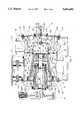
- FIG. 1is a side sectional view of a fibrous stock slurry screening apparatus in accordance with the invention in which fibrous stock slurry is introduced into a primary screening zone from the rear of a screen means and in which the rotor rotates in a fixed axial position and the screen is moved axially to adjust clearance between blades on the rotor and the screen.
- FIG. 2Ais a side sectional view of the screen means and a portion of the screen mounting means shown in FIG. 1.
- FIG. 2Bis an end view of the screen means shown in FIG. 2A, showing, in phantom detail, a portion of the engagement means of an adjustment screw.
- FIG. 3is a side sectional view of a screening apparatus in accordance with the invention in which fibrous stock slurry is introduced into a primary screening zone from the rear of a screen means and in which the screen is fixed and the rotor is axially displaced to adjust clearance between the rotor and the screen.
- FIG. 4is a side sectional view of a screening apparatus in accordance with the invention in which fibrous stock slurry is introduced into a primary screening zone from the front of the apparatus and in which the rotor rotates in a fixed axial position and the screen is axially displaced to adjust clearance between the rotor and the screen.
- FIG. 5Ais a sectional view of a screening apparatus in accordance with the invention, having a flat, diametrical plate that is adjusted forward or backward to control the clearance between it and the flat, diametrical rotor assembly.
- FIG. 5Bis a front view of a portion of the rotor of the apparatus shown in FIG. 5A.
- FIG. 5Cis a front view of a portion of the screen plate of the apparatus shown in FIG. 5A.
- FIG. 6Ais a view of an alternate embodiment of the invention having a cylindrical screen and a frusto-conical rotor, in which the distance between the blades and the rotor may be adjusted by a radial adjustment means.
- FIG. 6Bshows a detail of the end of the rotor and the attachment of both the adjustment means and the blades to the rotor.
- FIG. 6Cshows a detail of the blade attachment means.
- the fibrous stock screening apparatus 11 of the present inventionillustrated in FIG. 1, is used in separating various sized debris from a submerged pulp slurry.
- An explanation of the novel sections of the screening apparatus 11, along with an abbreviated explanation of the conventional portions sufficient to permit an understanding of the novel featuresfollows.
- a better understanding of the conventional portions of the designmay be obtained by reference to the above-mentioned prior art references, and particularly U.S. Pat. No. 4,744,894.
- Apparatus 11includes a housing member 13 having a substantially hollow interior 15, a screen means 17 located within the substantially hollow interior 15, and a rotor means 19 located within the interior.
- the screen means 17includes a frusto-conical screen member 29, which has apertures for screening, mounted within substantially hollow interior 15 for dividing the interior into a screened zone 31 and a screening zone, and for allowing acceptable stock to pass from the screening zone into the screened zone 31.
- An accepts outlet means or port 39is provided for communicating with the screened zone 31 for allowing acceptable stock which passes through the frusto-conical screen member 29 into the screened zone 31 to exit the interior 15 therethrough.
- Screen means 17also includes an extended portion 41, which is preferably cylindrical in shape rather than frusto-conical, and need not, in this embodiment, be provided with apertures for screening.
- Extended portion 41extends past a first coupling means 35 (which is fixedly and stationarily attached to housing member 13) towards a first end 23 of housing member 13.
- First coupling means 35slidingly and sealingly surrounds the cylindrical extended portion 41 of screen means 17, effectively separating slurry entry region 88 in the interior 15 of housing member 13 from screened zone 31.
- a mounting ring 80is preferably provided around screen means 17 to engage first coupling means 35 in such a manner as to provide a limit to the axial sliding motion of screen means 17.
- the sliding engagementmay be enhanced by other means, such as guide pins 82 slidingly and slidingly engaged in holes 86 in coupling means 35 and threaded through holes 84 in mounting ring 80.
- Limit stops for the axial sliding motion of screen means 17may thus be provided by the mounting ring 80 in one direction, and by heads 90 on guide pins 82 in the other direction.
- mounting ring 80is located where cylindrical extended portion 41 of screen means 17 meets screening member 29.
- Frusto-conical screen member 29is also provided with a sliding engagement means 38, which slidingly and sealingly engages a structure 37 fixedly mounted on a second end 24 of housing member 13.
- Structure 37is an annular structure which also cooperates with sliding engagement means 38 to separate screened zone 31 from reject zone 154.
- Reject zone 154is in fluid communication with a reject cavity 156 in supporting gusset 158 which in turn is in fluid communication with a port for a rejected portion of a slurry; i.e., that portion that does not make it through apertures in frusto-conical screen member 29.
- Reject zone 154is an annular chamber bounded on the inner circumference by the rotor means 19 and on the outer circumference by the sliding engagement means 38 (i.e., the seating ring) of the screen means 17.
- An openingleads from reject zone 154 to reject cavity 156 in supporting gusset 158, and to an outlet (not shown in FIG. 1).
- Rotor means 19is provided to contribute to the screening efficiency.
- Rotor means 19preferably includes a rotor body member 55 located coaxially within the interior of frusto-conical screen member 29.
- the body member 55includes a frusto-conical wall 57.
- a primary screening zone 45is thus defined between frusto-conical wall 57 of rotor body member 55 and frusto-conical screen member 29.
- Rotor means 19is provided with a conventional drive means 81, which confers rotational motion along a longitudinal axis 27 common to both screen means 17 and rotor body member 55 by means of a conventional shaft and bearing assembly 83.
- Internal end 59 of rotor means 19is closed and is fixedly attached to the shaft and bearing assembly 83.
- a motor to drive the drive means 81may be placed on platform 153 which is Atop housing member 13.
- Rotor means 19preferably includes a plurality of blade members 67 attached to and spaced substantially evenly about the outer perimeter of body member 55.
- the blade membersare arranged to allow a slight distance between the blade members 67 and screen member 29 to permit a layer of stock to be formed therebetween to allow proper screening to occur.
- the blade membersmay be of various cross-sectional shapes, as will be understood by those skilled in the art, and may generally be similar to the blade members of U.S. Pat. No. 4,744,894, except for their arrangement on a frusto-conical body member 55 rather than a cylindrical body member.
- the distance between the blade members 67 and the screen member 29is adjustable by inventive means to be described below.
- Fibrous stock or slurryis introduced into slurry entry region 88 of substantially hollow interior 15 through stock inlet means 51.
- Stock or slurry entering through stock inlet means 51flows through slurry entry region 88 and into the hollow interior 47 of extended portion 41 through inlets disposed at the end 48 of extended portion 41.
- FIGS. 2A and 2Bshow, respectively, a side cut-away view of rotor means 19 and an end view of the rotor means.
- end 48 of extended portion 41has a continuous, preferably circular rim 42.
- a number of preferably equiangularly spaced spokes 44radiate from the center of end 48 to rim 42.
- Spokes 44 and rim 42define a plurality of pie-shaped inlet regions 46 through which a pulp slurry can enter the hollow interior 47 of extended portion 41.
- One of the inlet regions 46has a slot 52 extending from a central angle into the center of end 48 for accepting a thrust ring 118, shown in phantom outline in FIG. 2B. Thrust ring 118 is inserted into slot 52 by inserting it into the associated pie-shaped region 46, as indicated by phantom outline 118A.
- Thrust ring 118may then be easily engaged in slot 52 by sliding it into position. It will be evident to those skilled in the art that many other configurations of end 48 of extended portion 41 will also provide a suitably engagable slot 52. (Another example of a suitable configuration is described below in connection with FIGS. 5A, 5B, and 5C.
- adjustment screw 100is provided to facilitate adjustment of the screen to rotor clearance. Rotor clearance is adjusted by changing the axial displacement of screen assembly 17.
- End 23 of apparatus 11is provided with an access door 130, which may be hinged to housing member 13, but which is fixedly attached to end 23 by conventional means 131 when apparatus 11 is in operation.
- Access door 130has an opening 138 surrounding axis 27.
- Adjustment plate 104is fixedly attached to access door 130 by conventional means 105.
- Adjustment plate 104also has a threaded aperture 103 around axis 27 for accepting threads 102 of adjustment screw 100.
- Sealing means, such as assembly 115 and O-ring 114are provided to sealingly engage adjustment screw so that slurry in initial screening zone 43 will not leak through adjustment plate 104.
- Thrust ring 118is fixedly attached to an end of adjustment screw 100 by attachment means such as bolt 116 and washers 120. It will be recognized that adjustment plate 104 may be attached to access door 130 in a manner by which thrust ring 118 engages slot 52 (shown in FIG. 2), thus operatively engaging adjustment screw 100 with structure 47 so that an adjustable displacement of screen assembly 17 along axis 27 may be obtained by turning adjustment handle 110, while thrust ring 118 rotates in slot 52. Displacement is accommodated by the sliding, sealing fit of first coupling means 35 around extend portion 41 of screen means 17, of guide pins 82 through holes 86, and structure 37 and engagement means 38.
- Markings 108 on the shaft of adjustment screw 100in cooperation with indicator 106 on adjustment plate 104, provide a visual indication of the relative axial movement of the screen assembly 17 with respect to the rotor 19.
- Rotor 19, in this embodimentrotates, but is not displaced axially.
- a dilution compartment 270Between this housing and the inside of rotor shell 55 is a dilution compartment 270. Dilution liquid is fed to this compartment through an annular opening 210 between a bearing housing 205, which is stationarily mounted on gusset 158, and the drive end frame 24. Dilution enters this opening from a dilution inlet pipe 250.
- a number of chocks 252are fitted around annular opening 210.
- Diluententers the screening zone 45 from the dilution compartment 270 through a plurality of holes 220 in rotor shell 55. These holes are spaced in such a manner as to lie under a trailing edge of a rotor blade 67.
- the clearance between frusto-conical screen section 29 and rotor blades 67may readily be calculated from the displacement indicated by indicator 106, the relative angles of frusto-conical screen section 29 and rotor 55, and the dimensions of blades 67. It will further be appreciated that this angle may be increased or decreased by the movement of adjustment screw 100 during operation of the apparatus while the apparatus is in operation.
- a slurryis introduced into stock inlet means 51.
- the slurrypasses into a region between a cylindrical door shroud 150, shown in cut-away section in FIG. 1, and extended portion 41 of screen means 17, and into hollow interior 47 of extended portion 41 as shown by arrow A.
- a port or trash trap 152is provided for removal of heavy foreign items in the slurry, e.g., bolts, that would damage apparatus 11 if they entered primary screening zone 45. Slurry that enters hollow interior 47 of extended portion 41 drains towards primary screening zone 45.
- a first screened portioni.e., the "accepts"
- the quality of the screening actionmay be controlled by adjusting the distance between the blade members 67 and frusto-conical screen member 29 as indicated above.
- Acceptsenter screened zone 31, and are drained from accepts outlet means or port 39.
- Slurry material that does not pass through apertures in frusto-conical screen member 29passes into reject zone 154, and into region 156 in gusset 158, as indicated by arrows B and C. From region 156, the rejected material may be drained or otherwise removed.
- the pulp that is exiting through frusto-conical screen member 29is at a minimum velocity--for example, approximately 5 ft./sec.
- the tip speed of blade members 67may be, for example, approximately 65 ft./sec., thus creating zones of pressure around the blades.
- the form and extent of these disturbances as a function of time and spaceare determined by the shape of the blades, which may be, for example, simple square bars or complex hydrofoils--the invention works equally well with these and other shapes--thus, the selection of particular blade members 67 can be based upon the desired requirements for the particular application such as, for example, the nature of the particular fibrous slurry, the type of debris to be removed and the end product requirements, for the application.
- Shaft and bearing assembly 83may be adjusted axially as indicated by arrow G while rotating as indicated by arrow F, thus moving rotor means 19 relative to screen means 17.
- a portion 185 of the shaft of the shaft and bearing assembly 83 outside of housing member 13may be provided with cogs that engage a gear on a motor drive (not shown in FIG. 3.), thus allowing shaft and bearing assembly 83 to be axially displaced while remaining operatively engaged with the motor.
- the adjustable axial motionchanges the spacing between blade members 67 and frusto-conical screen member 29. Because this spacing controls the movement of and pressure gradients in the slurry within primary screening zone 45, the quality of accepts exiting through apertures in frusto-conical screen member 29 into screened zone 31, as indicated by arrows D, can be controlled.
- FIG. 4is a simplified cross-sectional diagram of a screening device in accordance with the invention showing that slurry can also be provided in the front of the fibrous stock screening apparatus.
- screen means 17is axially adjustable by means of an adjustment screw 100 or other means as indicated by arrow G, although rotor means 19 could alternately be adjusted, as in FIG. 3.
- slurryenters primary screening zone 45 through a front opening, as indicated by arrow A.
- Acceptsare screened through apertures in frusto-conical screen member 29 as indicated by arrows D and exit through accepts outlet means or port 39, as indicated by arrow E.
- Region 88 in this embodimentbecomes a slurry exit region, as indicated by the path of rejects shown by arrow C.
- FIGS. 1-4employ blade members 67 to move the fibrous stock in primary screening zone 45, and thus, it is the clearance between blade members 67 and frusto-conical screen member 29 that is critical to the screening quality of the apparatus. If a means other than blade members 67 are used to move the stock (e.g., grooves or other features in or on rotor body member 55), the clearance in primary screening zone 45 will, of course, be measured as the distance between frusto-conical screen member 29 and some other structure on rotor body member 55.
- FIG. 5Ais an illustration of an embodiment of the invention in which a planar screen means and a planar circular rotor means are used, with the clearance between the screen means and the circular rotor means adjusted through an axial adjustment means.
- Both the planar rotor and the planar screenare disposed in a cylindrical interior portion of a housing, and the planes of the rotor and screens are both perpendicular to the axis of the cylindrical interior portion.
- the rotor and screeneach comprise a parallel plate defining the primary screening region therebetween.
- a circular rotor 515is rotated by a shaft and bearing assembly 83 by drive means 81.
- At least one, and preferably a plurality of blades 516are provided on rotor 515. Blades 516 are spaced apart from a perforated screen plate 518, thereby forming a primary screening region 517 therebetween.
- a supporting structure including a spacing means 520 and adjustment support spokes 522are provided for screen plate 518. This supporting structure is operatively coupled to an adjustment screw 100, which, as in previously described embodiments, provides an adjustment for the spacing between the blades 516 and the screen plate 518 in an axial direction.
- the rotor 515may also comprise a plurality of rotor gussets 510 for added strength and for mounting to a shaft mounting means 512.
- Slurryis introduced, as shown by arrow A, through a stock inlet means 524, into a slurry entry region 526.
- a sufficient flow of slurryis provided to ensure that only a portion is expelled through rejects port 528 as indicated by arrow B, and that an adequate amount of accepts enters accepts region 530 and exits through accepts port 531, as shown by arrow C.
- FIG. 5Bshows additional details of the rotor 515 in this embodiment, as it would be seen looking from the right side of FIG. 5A.
- a circular rim 514is provided with gaps 532 through which slurry may pass.
- Portions of rotor gussets 510 (not seen in FIG. 5B) in the preferred rotor configurationalso serve as spokes 550 of rotor 515 upon which blades 516 are mounted.
- FIG. 5Cshows a detail of a preferred perforated screen plate 518 and its associated structures as seen from the right of FIG. 5A.
- Screen plate 518which is partially hidden in this view, is provided with suitable perforations 534 (only a portion of which are shown for clarity) through which the accepts portion of the slurry passes.
- a circular rim 536which is affixed to or preferably integral with supporting structure 520, is provided with spokes 552 defining a teardrop-shaped aperture 540 into which thrust ring 120 is mounted.
- FIG. 5Cshows an equally acceptable alternate mounting configuration to that shown in FIG. 2B for the thrust ring.
- Filtered slurryexits through the gaps 538 between the spokes 552.
- FIG. 5Ashows slurry being introduced on the rotor side of the screening apparatus, it is also possible to introduce slurry on the screen side, instead.
- a feeding arrangement for a flat plate embodimentproduces very clean pulp, it also tends to have lower capacity than the rotor-side feed arrangement, which utilizes the rotor action to best advantage.
- FIGS. 6AYet another alternate embodiment of the invention, in which a cylindrical screen rather than a frusto-conical or planar screen is used, is illustrated in FIGS. 6A.
- Cylindrical screen member 329may be fixedly held within housing member 13 of this embodiment by means of bolts 382 fixedly attaching flange 380 of the cylindrical screen member 329 to an internal attachment structure 335.
- An adjustment member 341preferably having a cylindrical shape is provided for adjusting the clearance between blade members 367 and cylindrical screen member 329 in primary screening zone 45.
- Adjustment memberis provided with an end 348, which is better seen in FIG. 6B.
- End 348comprises a continuous, preferably circular rim 42.
- a mounting flange 410is disposed opposite end 348 of adjustment member 341, as illustrated in FIG. 6A.
- Mounting flange 410is provided with at least one, and preferably a plurality of radially elongate mounting apertures 412, which are best seen in FIG. 6B.
- Blade members 367are slidably engaged with mounting flange 410 in a radial direction by means of attachment screws 414 through elongate mounting apertures 412 or other suitable means. Referring to FIG. 6A, each of the blade members 367 is also slidably engaged with a corresponding blade engagement structure 416 affixed to frusto-conical wall 57 of rotor body member 55. Blade engagement structures 416 may be seen to better advantage in FIG.
- each blade engagement structure 416is joined with a blade member 367 via a sliding dovetail joint comprising walls 418 and 420.
- thrust ring 118which is engaged in slot 52 of end 348, causes an axial translation of mounting flange 410, which causes blade members 367 to ride up or down the inclined dovetail joints joining blade members 367 with blade engagement structures 416, which causes the clearance between blade members 367 and cylindrical screen member 329 to vary as blade members 367 travel along the inclined joints.
- Blade members 367are also rotated by the rotary movement of frusto-conical rotor wall 57, causing adjustment member 341 to rotate. The rotation of adjustment member 341 is isolated from adjustment screw 100 by the rotation of slot 52 around thrust ring 118.
- slurryenters through stock inlet means 51 illustrated in FIG. 6A.
- the slurrycan enter primary screening zone 45 directly through an end of cylindrical screen member 329 proximate stock inlet means 51, as shown by arrow A, and/or through inlet regions 46, as shown by arrow A'. In the latter case, the slurry will enter primary screening zone 45 in regions between blade members 367 near mounting flange 410.
- Rotation of frusto-conical wall 57imparts motion to the slurry in primary screening zone 45, so that an accepts portion of the slurry passes through apertures in cylindrical screen member 329 into screened zone 31.
- the accepts portionexits screened zone 31 through accepts outlet means or port 39.
- Rejectsenter reject zone 154, as in the embodiment of FIG. 1.
- the pressure and movement of the slurry in the primary screening zoneis controlled, and thus throughput rate and accept quality can be controlled.
- control of the clearancemay be accomplished without stopping the screen to dismantle components, thereby allowing quality and rate to be continuously monitored, and controlled without the necessity to stop production.
- Blade inventorycan be reduced, because the control of quality and rate afforded by the invention allows each blade size and type to perform in a variety of applications, for various slurry types.
- As blades or screens become worn, and thus, their performance characteristics change, their lifecan be extended by compensating for the changed characteristics by adjusting the clearance between the screen means and the rotor.
Landscapes
- Engineering & Computer Science (AREA)
- Mechanical Engineering (AREA)
- Paper (AREA)
Abstract
Description
Claims (7)
Priority Applications (1)
| Application Number | Priority Date | Filing Date | Title |
|---|---|---|---|
| US08/273,467US5601690A (en) | 1994-07-11 | 1994-07-11 | Method for screening pulp |
Applications Claiming Priority (1)
| Application Number | Priority Date | Filing Date | Title |
|---|---|---|---|
| US08/273,467US5601690A (en) | 1994-07-11 | 1994-07-11 | Method for screening pulp |
Publications (1)
| Publication Number | Publication Date |
|---|---|
| US5601690Atrue US5601690A (en) | 1997-02-11 |
Family
ID=23044061
Family Applications (1)
| Application Number | Title | Priority Date | Filing Date |
|---|---|---|---|
| US08/273,467Expired - LifetimeUS5601690A (en) | 1994-07-11 | 1994-07-11 | Method for screening pulp |
Country Status (1)
| Country | Link |
|---|---|
| US (1) | US5601690A (en) |
Cited By (32)
| Publication number | Priority date | Publication date | Assignee | Title |
|---|---|---|---|---|
| US5954956A (en)* | 1997-07-22 | 1999-09-21 | J&L Fiber Services | Modular screen cylinder and a method for its manufacture |
| US6138838A (en)* | 1998-05-29 | 2000-10-31 | J&L Fiber Services, Inc. | Screen media and a screening passage therefore |
| US6171448B1 (en)* | 1998-02-03 | 2001-01-09 | Ishikawajima-Harima Jukogyo Kabushiki Kaisha | Apparatus for screening waste paper pulp |
| US6238523B1 (en)* | 1996-06-18 | 2001-05-29 | Sep Technologies Llc | Decontamination apparatus |
| US6524320B2 (en)* | 2001-05-15 | 2003-02-25 | Endius Incorporated | Cannula for receiving surgical instruments |
| US20030073998A1 (en)* | 2000-08-01 | 2003-04-17 | Endius Incorporated | Method of securing vertebrae |
| US20030195551A1 (en)* | 1998-08-20 | 2003-10-16 | Davison Thomas W. | Cannula for receiving surgical instruments |
| US6719145B1 (en)* | 1999-11-29 | 2004-04-13 | Andritz Oy | Arrangement and rotor for screening of pulp |
| US20040078051A1 (en)* | 1998-08-20 | 2004-04-22 | Davison Thomas W. | Cannula for receiving surgical instruments |
| US20040097907A1 (en)* | 2001-05-15 | 2004-05-20 | Dipoto Gene P. | Cannula for receiving surgical instruments |
| US6752165B2 (en) | 2000-03-08 | 2004-06-22 | J & L Fiber Services, Inc. | Refiner control method and system |
| US20040133201A1 (en)* | 2000-08-01 | 2004-07-08 | Alan Shluzas | Methods and apparatuses for treating the spine through an access device |
| US6778936B2 (en) | 2000-03-08 | 2004-08-17 | J & L Fiber Services, Inc. | Consistency determining method and system |
| US20050045530A1 (en)* | 2003-09-02 | 2005-03-03 | Gl&V Management Hungary Kft | Rotor with multiple foils for screening apparatus for papermaking pulp |
| US20050090899A1 (en)* | 2003-10-24 | 2005-04-28 | Dipoto Gene | Methods and apparatuses for treating the spine through an access device |
| US20050090822A1 (en)* | 2003-10-24 | 2005-04-28 | Dipoto Gene | Methods and apparatus for stabilizing the spine through an access device |
| US6892973B2 (en) | 2000-03-08 | 2005-05-17 | J&L Fiber Services, Inc. | Refiner disk sensor and sensor refiner disk |
| US6938843B2 (en) | 2001-03-06 | 2005-09-06 | J & L Fiber Services, Inc. | Refiner control method and system |
| US20050211809A1 (en)* | 2004-03-23 | 2005-09-29 | J&L Fiber Services, Inc. | Refiner sensor and coupling arrangement |
| US20070233089A1 (en)* | 2006-02-17 | 2007-10-04 | Endius, Inc. | Systems and methods for reducing adjacent level disc disease |
| US7655012B2 (en) | 2003-10-02 | 2010-02-02 | Zimmer Spine, Inc. | Methods and apparatuses for minimally invasive replacement of intervertebral discs |
| US7658739B2 (en) | 2005-09-27 | 2010-02-09 | Zimmer Spine, Inc. | Methods and apparatuses for stabilizing the spine through an access device |
| US7731737B2 (en) | 2003-10-24 | 2010-06-08 | Zimmer Spine, Inc. | Methods and apparatuses for fixation of the spine through an access device |
| US7799036B2 (en) | 1998-08-20 | 2010-09-21 | Zimmer Spine, Inc. | Method and apparatus for securing vertebrae |
| US20110005980A1 (en)* | 2006-05-10 | 2011-01-13 | Tsukasa Co., Ltd. | Sifter |
| US9556916B2 (en) | 2013-03-15 | 2017-01-31 | Whirlpool Corporation | High performance adjustable juicer with whole foods feed chute and clutch mechanism |
| US9675101B2 (en) | 2013-03-15 | 2017-06-13 | Whirlpool Corporation | High performance adjustable juicer with whole foods feed chute |
| US10226774B2 (en)* | 2015-02-23 | 2019-03-12 | Fluid Quip, Inc. | Multi-zoned paddle screen apparatus |
| US20200002890A1 (en)* | 2018-06-29 | 2020-01-02 | Jeffrey Leigh Jennings | Paper pulp pressure screen |
| WO2020193003A1 (en)* | 2019-03-26 | 2020-10-01 | Voith Patent Gmbh | Pressure screen, screen element and method for manufacturing a screen element |
| CN113584923A (en)* | 2021-09-01 | 2021-11-02 | 安德里茨(中国)有限公司 | Pulp screening machine |
| US20220339562A1 (en)* | 2019-10-04 | 2022-10-27 | Mimbly Ab | Improved filter assembly with self-cleaning |
Citations (20)
| Publication number | Priority date | Publication date | Assignee | Title |
|---|---|---|---|---|
| US3656528A (en)* | 1970-02-19 | 1972-04-18 | Int Machinery Corp Sa | Pulping and finishing apparatus |
| US3664501A (en)* | 1969-11-21 | 1972-05-23 | Ben Cowan | Pulp screening machine |
| US3814244A (en)* | 1972-05-30 | 1974-06-04 | Ingersoll Rand Canada | Apparatus for fractionating fluid suspensions |
| US3939065A (en)* | 1972-08-31 | 1976-02-17 | Ahlfors S E E | Screening device |
| US4234417A (en)* | 1979-03-29 | 1980-11-18 | Gauld Equipment Manufacturing Co. | Fibrous stock screen |
| US4267035A (en)* | 1979-08-27 | 1981-05-12 | The Black Clawson Company | Pressurized rotary screening apparatus |
| US4374728A (en)* | 1981-07-29 | 1983-02-22 | Gauld W Thomas | Apparatus for screening fibrous stock |
| US4462901A (en)* | 1981-12-28 | 1984-07-31 | Gauld W Thomas | Apparatus for screening fibrous stock |
| US4605173A (en)* | 1984-04-04 | 1986-08-12 | Edmonds Harvey A | Size reduction machine |
| US4744894A (en)* | 1986-06-30 | 1988-05-17 | Gauld W Thomas | Fibrous stock screening apparatus |
| US4754935A (en)* | 1986-04-10 | 1988-07-05 | Kamyr Ab | Method and apparatus for refining fibrous material |
| US4819881A (en)* | 1986-12-11 | 1989-04-11 | Sulzer-Escher Wyss Gmbh | Refiner for processing a fiber stock suspension for paper fabrication |
| US4907750A (en)* | 1988-03-09 | 1990-03-13 | Prater Industries, Inc. | Hammermill |
| US4943347A (en)* | 1985-08-20 | 1990-07-24 | Mats Floden | Method of refining fibrous material by controlling the feed rate of material or the gap distance between discs |
| US4955549A (en)* | 1986-08-07 | 1990-09-11 | Sunds Defibrator Aktiebolag | Apparatus for treatment of fibre suspensions |
| US4968417A (en)* | 1988-06-16 | 1990-11-06 | Kamyr Ab | Apparatus for screening a suspension of fibrous cellulose pulp |
| US4986480A (en)* | 1989-06-29 | 1991-01-22 | Kamyr Ab | Method and apparatus for feeding a conical refiner |
| US5061370A (en)* | 1990-03-20 | 1991-10-29 | Quebec And Ontario Paper Company Ltd. | Screening device for slurries with improved rotor and hub design |
| US5282579A (en)* | 1993-01-25 | 1994-02-01 | Poser Kimberly J | Apparatus for adjusting the gap of a size reduction machine |
| US5358637A (en)* | 1989-02-18 | 1994-10-25 | Herman Finckh Maschinenfabrik Gmbh & Co. | Apparatus for sorting and deflaking fibrous suspensions |
- 1994
- 1994-07-11USUS08/273,467patent/US5601690A/ennot_activeExpired - Lifetime
Patent Citations (20)
| Publication number | Priority date | Publication date | Assignee | Title |
|---|---|---|---|---|
| US3664501A (en)* | 1969-11-21 | 1972-05-23 | Ben Cowan | Pulp screening machine |
| US3656528A (en)* | 1970-02-19 | 1972-04-18 | Int Machinery Corp Sa | Pulping and finishing apparatus |
| US3814244A (en)* | 1972-05-30 | 1974-06-04 | Ingersoll Rand Canada | Apparatus for fractionating fluid suspensions |
| US3939065A (en)* | 1972-08-31 | 1976-02-17 | Ahlfors S E E | Screening device |
| US4234417A (en)* | 1979-03-29 | 1980-11-18 | Gauld Equipment Manufacturing Co. | Fibrous stock screen |
| US4267035A (en)* | 1979-08-27 | 1981-05-12 | The Black Clawson Company | Pressurized rotary screening apparatus |
| US4374728A (en)* | 1981-07-29 | 1983-02-22 | Gauld W Thomas | Apparatus for screening fibrous stock |
| US4462901A (en)* | 1981-12-28 | 1984-07-31 | Gauld W Thomas | Apparatus for screening fibrous stock |
| US4605173A (en)* | 1984-04-04 | 1986-08-12 | Edmonds Harvey A | Size reduction machine |
| US4943347A (en)* | 1985-08-20 | 1990-07-24 | Mats Floden | Method of refining fibrous material by controlling the feed rate of material or the gap distance between discs |
| US4754935A (en)* | 1986-04-10 | 1988-07-05 | Kamyr Ab | Method and apparatus for refining fibrous material |
| US4744894A (en)* | 1986-06-30 | 1988-05-17 | Gauld W Thomas | Fibrous stock screening apparatus |
| US4955549A (en)* | 1986-08-07 | 1990-09-11 | Sunds Defibrator Aktiebolag | Apparatus for treatment of fibre suspensions |
| US4819881A (en)* | 1986-12-11 | 1989-04-11 | Sulzer-Escher Wyss Gmbh | Refiner for processing a fiber stock suspension for paper fabrication |
| US4907750A (en)* | 1988-03-09 | 1990-03-13 | Prater Industries, Inc. | Hammermill |
| US4968417A (en)* | 1988-06-16 | 1990-11-06 | Kamyr Ab | Apparatus for screening a suspension of fibrous cellulose pulp |
| US5358637A (en)* | 1989-02-18 | 1994-10-25 | Herman Finckh Maschinenfabrik Gmbh & Co. | Apparatus for sorting and deflaking fibrous suspensions |
| US4986480A (en)* | 1989-06-29 | 1991-01-22 | Kamyr Ab | Method and apparatus for feeding a conical refiner |
| US5061370A (en)* | 1990-03-20 | 1991-10-29 | Quebec And Ontario Paper Company Ltd. | Screening device for slurries with improved rotor and hub design |
| US5282579A (en)* | 1993-01-25 | 1994-02-01 | Poser Kimberly J | Apparatus for adjusting the gap of a size reduction machine |
Non-Patent Citations (2)
| Title |
|---|
| "Stock Preparation," Hanbook of Pulp and Paper Technology, pp. 305-307, (date unknown). |
| Stock Preparation, Hanbook of Pulp and Paper Technology, pp. 305 307, (date unknown).* |
Cited By (77)
| Publication number | Priority date | Publication date | Assignee | Title |
|---|---|---|---|---|
| US6238523B1 (en)* | 1996-06-18 | 2001-05-29 | Sep Technologies Llc | Decontamination apparatus |
| US5954956A (en)* | 1997-07-22 | 1999-09-21 | J&L Fiber Services | Modular screen cylinder and a method for its manufacture |
| US6171448B1 (en)* | 1998-02-03 | 2001-01-09 | Ishikawajima-Harima Jukogyo Kabushiki Kaisha | Apparatus for screening waste paper pulp |
| US6138838A (en)* | 1998-05-29 | 2000-10-31 | J&L Fiber Services, Inc. | Screen media and a screening passage therefore |
| US7985237B2 (en) | 1998-08-20 | 2011-07-26 | Zimmer Spine, Inc. | Cannula for receiving surgical instruments |
| US8968351B2 (en) | 1998-08-20 | 2015-03-03 | Zimmer Spine, Inc. | Cannula for receiving surgical instruments |
| US20030195551A1 (en)* | 1998-08-20 | 2003-10-16 | Davison Thomas W. | Cannula for receiving surgical instruments |
| US20030195550A1 (en)* | 1998-08-20 | 2003-10-16 | Davison Thomas W. | Cannula for receiving surgical instruments |
| US20030199885A1 (en)* | 1998-08-20 | 2003-10-23 | Davison Thomas W. | Cannula for receiving surgical instruments |
| US20030199884A1 (en)* | 1998-08-20 | 2003-10-23 | Endius Incorporated | Method for performing a surgical procedure and a cannula for use in performing the surgical procedure |
| US20060264999A1 (en)* | 1998-08-20 | 2006-11-23 | Davison Thomas W | Cannula for receiving surgical instruments |
| US20040078051A1 (en)* | 1998-08-20 | 2004-04-22 | Davison Thomas W. | Cannula for receiving surgical instruments |
| US20040093002A1 (en)* | 1998-08-20 | 2004-05-13 | Davison Thomas W. | Cannula for receiving surgical instruments |
| US8317817B2 (en) | 1998-08-20 | 2012-11-27 | Zimmer Spine, Inc. | Cannula for receiving surgical instruments |
| US20040098012A1 (en)* | 1998-08-20 | 2004-05-20 | Davison Thomas W. | Cannula for receiving surgical instruments |
| US7001397B2 (en) | 1998-08-20 | 2006-02-21 | Endius Incorporated | Cannula for receiving surgical instruments |
| US7108705B2 (en) | 1998-08-20 | 2006-09-19 | Endius, Inc. | Cannula for receiving surgical instruments |
| US20060276822A1 (en)* | 1998-08-20 | 2006-12-07 | Davison Thomas W | Cannula for receiving surgical instruments |
| US6811558B2 (en) | 1998-08-20 | 2004-11-02 | Endius Incorporated | Method for performing a surgical procedure and a cannula for use in performing the surgical procedure |
| US8540746B2 (en) | 1998-08-20 | 2013-09-24 | Zimmer Spine, Inc. | Cannula for receiving surgical instruments |
| US7892249B2 (en) | 1998-08-20 | 2011-02-22 | Zimmer Spine, Inc. | Cannula for receiving surgical instruments |
| US7892171B2 (en) | 1998-08-20 | 2011-02-22 | Zimmer Spine, Inc. | Cannula for receiving surgical instruments |
| US20050043754A1 (en)* | 1998-08-20 | 2005-02-24 | Davison Thomas W. | Method for performing a surgical procedure and a cannula for use in performing the surgical procedure |
| US7799036B2 (en) | 1998-08-20 | 2010-09-21 | Zimmer Spine, Inc. | Method and apparatus for securing vertebrae |
| US7674273B2 (en) | 1998-08-20 | 2010-03-09 | Zimmer Spine, Inc. | Method for performing a surgical procedure and a cannula for use in performing the surgical procedure |
| US7670354B2 (en) | 1998-08-20 | 2010-03-02 | Zimmer Spine, Inc. | Cannula for receiving surgical instruments |
| US20060276821A1 (en)* | 1998-08-20 | 2006-12-07 | Davison Thomas W | Cannula for receiving surgical instruments |
| US7641670B2 (en) | 1998-08-20 | 2010-01-05 | Zimmer Spine, Inc. | Cannula for receiving surgical instruments |
| US7223278B2 (en) | 1998-08-20 | 2007-05-29 | Endius, Inc. | Cannula for receiving surgical instruments |
| US6719145B1 (en)* | 1999-11-29 | 2004-04-13 | Andritz Oy | Arrangement and rotor for screening of pulp |
| US6892973B2 (en) | 2000-03-08 | 2005-05-17 | J&L Fiber Services, Inc. | Refiner disk sensor and sensor refiner disk |
| US6778936B2 (en) | 2000-03-08 | 2004-08-17 | J & L Fiber Services, Inc. | Consistency determining method and system |
| US6752165B2 (en) | 2000-03-08 | 2004-06-22 | J & L Fiber Services, Inc. | Refiner control method and system |
| US20040236317A1 (en)* | 2000-08-01 | 2004-11-25 | Davison Thomas W. | Method of securing vertebrae |
| US8777997B2 (en) | 2000-08-01 | 2014-07-15 | Zimmer Spine, Inc. | Method for securing vertebrae |
| US7056321B2 (en) | 2000-08-01 | 2006-06-06 | Endius, Incorporated | Method of securing vertebrae |
| US9622735B2 (en) | 2000-08-01 | 2017-04-18 | Zimmer Spine, Inc. | Method for securing vertebrae |
| US9101353B2 (en) | 2000-08-01 | 2015-08-11 | Zimmer Spine, Inc. | Method of securing vertebrae |
| US8864785B2 (en) | 2000-08-01 | 2014-10-21 | Zimmer Spine, Inc. | Method for securing vertebrae |
| US20030073998A1 (en)* | 2000-08-01 | 2003-04-17 | Endius Incorporated | Method of securing vertebrae |
| US8277486B2 (en) | 2000-08-01 | 2012-10-02 | Zimmer Spine, Inc. | System for performing a procedure at a spinal location |
| US20050113833A1 (en)* | 2000-08-01 | 2005-05-26 | Davison Thomas W. | Method of securing vertebrae |
| US20040133201A1 (en)* | 2000-08-01 | 2004-07-08 | Alan Shluzas | Methods and apparatuses for treating the spine through an access device |
| US7985247B2 (en) | 2000-08-01 | 2011-07-26 | Zimmer Spine, Inc. | Methods and apparatuses for treating the spine through an access device |
| US20050021030A1 (en)* | 2000-08-01 | 2005-01-27 | Endius Incorporated | Method of securing vertebrae |
| US20050033297A1 (en)* | 2000-08-01 | 2005-02-10 | Davison Thomas W. | Method of securing vertebrae |
| US7850695B2 (en) | 2000-08-01 | 2010-12-14 | Zimmer Spine, Inc. | Method of securing vertebrae |
| US7699877B2 (en) | 2000-08-01 | 2010-04-20 | Zimmer Spine, Inc. | Method of securing vertebrae |
| US7722530B2 (en) | 2000-08-01 | 2010-05-25 | Zimmer Spine, Inc. | Method of securing vertebrae |
| US6938843B2 (en) | 2001-03-06 | 2005-09-06 | J & L Fiber Services, Inc. | Refiner control method and system |
| US8007492B2 (en) | 2001-05-15 | 2011-08-30 | Zimmer Spine, Inc. | Cannula for receiving surgical instruments |
| US7766930B2 (en) | 2001-05-15 | 2010-08-03 | Zimmer Spine, Inc. | Cannula for receiving surgical instruments |
| US20070142857A1 (en)* | 2001-05-15 | 2007-06-21 | Dipoto Gene P | Structure for receiving surgical instruments |
| US20040097907A1 (en)* | 2001-05-15 | 2004-05-20 | Dipoto Gene P. | Cannula for receiving surgical instruments |
| US6524320B2 (en)* | 2001-05-15 | 2003-02-25 | Endius Incorporated | Cannula for receiving surgical instruments |
| US7985218B2 (en) | 2001-05-15 | 2011-07-26 | Zimmer Spine, Inc. | Structure for receiving surgical instruments |
| US20050045530A1 (en)* | 2003-09-02 | 2005-03-03 | Gl&V Management Hungary Kft | Rotor with multiple foils for screening apparatus for papermaking pulp |
| US6942104B2 (en) | 2003-09-02 | 2005-09-13 | Gl&V Management Hungary Kft. | Rotor with multiple foils for screening apparatus for papermaking pulp |
| US7655012B2 (en) | 2003-10-02 | 2010-02-02 | Zimmer Spine, Inc. | Methods and apparatuses for minimally invasive replacement of intervertebral discs |
| US20050090822A1 (en)* | 2003-10-24 | 2005-04-28 | Dipoto Gene | Methods and apparatus for stabilizing the spine through an access device |
| US7731737B2 (en) | 2003-10-24 | 2010-06-08 | Zimmer Spine, Inc. | Methods and apparatuses for fixation of the spine through an access device |
| US20050090899A1 (en)* | 2003-10-24 | 2005-04-28 | Dipoto Gene | Methods and apparatuses for treating the spine through an access device |
| US7104480B2 (en) | 2004-03-23 | 2006-09-12 | J&L Fiber Services, Inc. | Refiner sensor and coupling arrangement |
| US20050211809A1 (en)* | 2004-03-23 | 2005-09-29 | J&L Fiber Services, Inc. | Refiner sensor and coupling arrangement |
| US7658739B2 (en) | 2005-09-27 | 2010-02-09 | Zimmer Spine, Inc. | Methods and apparatuses for stabilizing the spine through an access device |
| US20070233089A1 (en)* | 2006-02-17 | 2007-10-04 | Endius, Inc. | Systems and methods for reducing adjacent level disc disease |
| US20100069961A1 (en)* | 2006-02-17 | 2010-03-18 | Zimmer Spine, Inc. | Systems and methods for reducing adjacent level disc disease |
| US8240481B2 (en)* | 2006-05-10 | 2012-08-14 | Tsukasa Co., Ltd. | Sifter |
| US20110005980A1 (en)* | 2006-05-10 | 2011-01-13 | Tsukasa Co., Ltd. | Sifter |
| US9556916B2 (en) | 2013-03-15 | 2017-01-31 | Whirlpool Corporation | High performance adjustable juicer with whole foods feed chute and clutch mechanism |
| US9675101B2 (en) | 2013-03-15 | 2017-06-13 | Whirlpool Corporation | High performance adjustable juicer with whole foods feed chute |
| US10226774B2 (en)* | 2015-02-23 | 2019-03-12 | Fluid Quip, Inc. | Multi-zoned paddle screen apparatus |
| US20200002890A1 (en)* | 2018-06-29 | 2020-01-02 | Jeffrey Leigh Jennings | Paper pulp pressure screen |
| WO2020193003A1 (en)* | 2019-03-26 | 2020-10-01 | Voith Patent Gmbh | Pressure screen, screen element and method for manufacturing a screen element |
| US20220339562A1 (en)* | 2019-10-04 | 2022-10-27 | Mimbly Ab | Improved filter assembly with self-cleaning |
| US12208348B2 (en)* | 2019-10-04 | 2025-01-28 | Mimbly Ab | Conical filter with turbine powered scraper |
| CN113584923A (en)* | 2021-09-01 | 2021-11-02 | 安德里茨(中国)有限公司 | Pulp screening machine |
Similar Documents
| Publication | Publication Date | Title |
|---|---|---|
| US5601690A (en) | Method for screening pulp | |
| US3726401A (en) | Screening machine | |
| EP0289020B1 (en) | Method and apparatus for treating fiber suspension | |
| US3912622A (en) | Screening machine with lights removal | |
| US3849302A (en) | Method and apparatus for screening paper fiber stock | |
| DE3709623C2 (en) | ||
| US4234417A (en) | Fibrous stock screen | |
| DE69232085T2 (en) | FEED ACCELERATION SYSTEM WITH ACCELERATION DISC | |
| US4955549A (en) | Apparatus for treatment of fibre suspensions | |
| US5009774A (en) | Pulseless screen | |
| JPH0784717B2 (en) | Sorting device with a reducer | |
| JPH0696835B2 (en) | Device for dividing suspensions of fibrous cellulose pulp | |
| US4328096A (en) | Dual flow screening apparatus | |
| EP0650542B1 (en) | Screening apparatus for papermaking pulp | |
| US5172813A (en) | Method and an apparatus for treating fiber suspension | |
| CA1309978C (en) | Sorting apparatus for fiber suspensions | |
| EP0036328A2 (en) | Dual flow screening apparatus | |
| US3970548A (en) | Apparatus for screening paper fiber stock | |
| US5421176A (en) | Drum washer | |
| CA1330174C (en) | Method and apparatus for thickening fiber suspension | |
| US6669025B2 (en) | Screen | |
| JP3347733B2 (en) | Screen device with position adjustable wings | |
| EP0504161A1 (en) | Basket profile for screens. | |
| US5102532A (en) | Method for controlling pressurized screening devices and pressurized screening device | |
| CN1308089C (en) | Wet-type sorting device |
Legal Events
| Date | Code | Title | Description |
|---|---|---|---|
| AS | Assignment | Owner name:GAULD EQUIPMENT COMPANY, ALABAMA Free format text:ASSIGNMENT OF ASSIGNORS INTEREST;ASSIGNORS:GAULD, W. THOMAS;VISSER, RONALD;JEPSEN, ARTHUR V.;REEL/FRAME:007167/0172 Effective date:19941004 | |
| STCF | Information on status: patent grant | Free format text:PATENTED CASE | |
| AS | Assignment | Owner name:THERMO BLACK CLAWSON INC., OHIO Free format text:ASSIGNMENT OF ASSIGNORS INTEREST;ASSIGNOR:GAULD EQUIPMENT MANUFACTURING COMPANY, INC.;REEL/FRAME:010776/0060 Effective date:20000222 | |
| FPAY | Fee payment | Year of fee payment:4 | |
| FEPP | Fee payment procedure | Free format text:PAT HOLDER NO LONGER CLAIMS SMALL ENTITY STATUS, ENTITY STATUS SET TO UNDISCOUNTED (ORIGINAL EVENT CODE: STOL); ENTITY STATUS OF PATENT OWNER: LARGE ENTITY | |
| REFU | Refund | Free format text:REFUND - PAYMENT OF MAINTENANCE FEE, 8TH YR, SMALL ENTITY (ORIGINAL EVENT CODE: R2552); ENTITY STATUS OF PATENT OWNER: LARGE ENTITY | |
| FPAY | Fee payment | Year of fee payment:8 | |
| FPAY | Fee payment | Year of fee payment:12 |