US5601566A - Method and apparatus for the alignment of a femoral knee prosthesis - Google Patents
Method and apparatus for the alignment of a femoral knee prosthesisDownload PDFInfo
- Publication number
- US5601566A US5601566AUS08/199,069US19906994AUS5601566AUS 5601566 AUS5601566 AUS 5601566AUS 19906994 AUS19906994 AUS 19906994AUS 5601566 AUS5601566 AUS 5601566A
- Authority
- US
- United States
- Prior art keywords
- femur
- knee
- force
- mechanical axis
- patient
- Prior art date
- Legal status (The legal status is an assumption and is not a legal conclusion. Google has not performed a legal analysis and makes no representation as to the accuracy of the status listed.)
- Expired - Lifetime
Links
- 210000003127kneeAnatomy0.000titleclaimsabstractdescription77
- 238000000034methodMethods0.000titleabstractdescription12
- 210000000689upper legAnatomy0.000claimsabstractdescription101
- 210000002414legAnatomy0.000claimsabstractdescription17
- 239000000725suspensionSubstances0.000claimsdescription13
- 230000008878couplingEffects0.000claimsdescription8
- 238000010168coupling processMethods0.000claimsdescription8
- 238000005859coupling reactionMethods0.000claimsdescription8
- 239000007943implantSubstances0.000claimsdescription3
- 210000000629knee jointAnatomy0.000description10
- 210000002303tibiaAnatomy0.000description8
- 238000002271resectionMethods0.000description6
- 210000000988bone and boneAnatomy0.000description5
- 230000000007visual effectEffects0.000description5
- 210000003423ankleAnatomy0.000description3
- 210000000544articulatio talocruralisAnatomy0.000description3
- 230000000295complement effectEffects0.000description3
- 230000007774longtermEffects0.000description3
- 238000011477surgical interventionMethods0.000description3
- 238000001356surgical procedureMethods0.000description3
- 238000013459approachMethods0.000description2
- 238000003780insertionMethods0.000description2
- 230000037431insertionEffects0.000description2
- 239000000463materialSubstances0.000description2
- 239000002184metalSubstances0.000description2
- 238000002559palpationMethods0.000description2
- 208000005189EmbolismDiseases0.000description1
- 238000011882arthroplastyMethods0.000description1
- 238000010276constructionMethods0.000description1
- 238000013461designMethods0.000description1
- 238000005553drillingMethods0.000description1
- 230000000694effectsEffects0.000description1
- 238000001839endoscopyMethods0.000description1
- 210000002683footAnatomy0.000description1
- 230000005484gravityEffects0.000description1
- 210000004394hip jointAnatomy0.000description1
- 238000013150knee replacementMethods0.000description1
- 210000001699lower legAnatomy0.000description1
- 238000002360preparation methodMethods0.000description1
- 230000005855radiationEffects0.000description1
- 230000004083survival effectEffects0.000description1
- 238000011883total knee arthroplastyMethods0.000description1
Images


Classifications
- A—HUMAN NECESSITIES
- A61—MEDICAL OR VETERINARY SCIENCE; HYGIENE
- A61B—DIAGNOSIS; SURGERY; IDENTIFICATION
- A61B17/00—Surgical instruments, devices or methods
- A61B17/14—Surgical saws
- A61B17/15—Guides therefor
- A61B17/154—Guides therefor for preparing bone for knee prosthesis
- A61B17/155—Cutting femur
- A—HUMAN NECESSITIES
- A61—MEDICAL OR VETERINARY SCIENCE; HYGIENE
- A61B—DIAGNOSIS; SURGERY; IDENTIFICATION
- A61B17/00—Surgical instruments, devices or methods
- A61B17/14—Surgical saws
- A61B17/15—Guides therefor
- A61B17/154—Guides therefor for preparing bone for knee prosthesis
Definitions
- the present inventionrelates generally to method and apparatus for establishing the correct alignment and orientation for a femoral knee prosthesis during total knee arthroplasty surgery and pertains, more specifically, to determining the correct position and orientation of cutting guides with respect to a patient's femur so that the femur can be cut to fit the femoral knee prosthesis and the femoral knee prosthesis will be implanted in an anatomically correct orientation.
- the distal surfaces of the femurare cut away and replaced with a metal cap to simulate the bearing surfaces of the femur.
- the proximal surface of the tibialis modified in a similar way, to provide a metal-backed plastic bearing surface.
- the metal femoral component of the new prosthetic jointtransfers the weight of the patient to the tibial component such that the joint can support the patient's weight and provide a near-normal motion of the knee joint.
- the long term survival of a prosthetic knee jointis dependant on how accurately the components of the knee joint are implanted with respect to the weight bearing axis of the patient's leg.
- the weight bearing axispasses through the center of the head of the femur, the center of the knee and the center of the ankle joint. This weight bearing axis typically is located by analyzing an X-ray image of the patient's leg, taken while the patient is standing.
- the X-ray imageis used to locate the center of the head of the femur and to calculate the position of the head relative to selected landmarks on the femur.
- the selected landmarksare then found on the patient's femur during surgery and the calculations used to estimate the actual position of the femoral head.
- These two pieces of informationare used to determine the correct alignment of the weight bearing axis for the femur, commonly referred to as the mechanical axis of the femur.
- the correct relationship between the center of the femoral head and the knee joint and the rotation of the knee joint about the mechanical axis mastbe established. This information is determined from landmarks on the distal portion of the femur.
- the correct alignment for the tibial component of the knee prosthesisis determined by finding the center of the ankle joint and relating its position to landmarks on the tibia. This point and the center of the proximal tibial plateau are used to define the weight bearing axis, or mechanical axis, of the tibia.
- the correct relationship between the ankle joint and the knee joint and the rotation of the knee joint about the mechanical axisare determined by reference to the dista portion of the femur and landmarks on the tibial plateau.
- Various mechanical alignment instrumentsare used to assist the surgeon in making cuts on the distal femur and proximal tibia which will allow the femoral and tibial components of the prosthetic knee implant to be attached to the femur and tibia. These mechanical alignment instruments permit the surgeon to fix cutting guides in place with respect to the selected landmarks on the bones so that the cuts will be correctly oriented with respect to the mechanical axes determined from the X-ray image.
- Intramedullary alignment systemsuse the inside of the femur or tibia, the medullary canal, as one of the selected landmarks for establishing alignment.
- Extramedullary alignment systemsuse only the external surfaces of the body to establish alignment.
- a typical extramedullary alignment systemrequires the surgeon to visually align a slender rod with the center of the knee and the center of the femoral head for alignment of the femoral component, then align a similar rod with the center of the ankle and the center of the tibial plateau for alignment of the tibial component.
- the centers of the femoral head and ankleare found by palpation or are established with an intraoperative X-ray. If correctly placed, the rods will lie parallel no, and offset from the mechanical axes. Once aligned, the rods are used as a guide to fix the location of the cutting guides with respect to the femur and the tibia so that the cuts can be performed.
- a typical intramedullary alignment systemrequires the surgeon to insert rods into the medullary canal of the femur and of the tibia. If properly placed these rods should lie on the axis of the bones.
- the mechanical axisis very close to the axis of the bone.
- the axis of the boneis quite different from the mechanical axis due to the offset nature of the hip joint, and this difference must be measured from the pre-operative X-ray and used to correct the alignment of the femoral cutting guides.
- Extramedullary alignmentdepends on accurate visual estimation of the alignment of the extramedullary rods. Location of the femoral head by palpation is difficult and error-prone, particularly with obese patients.
- Use of intraoperative X-raysimproves the result somewhat, but is time consuming and exposes the patient and operating room personnel to radiation.
- X-raysalso are subject to distortion and require visual interpretation and estimation to analyze correctly, as X-rays offer only one planar view in two dimensions.
- Intramedullary alignment approachesprovide only sightly better results, in that the knee joint alignment is still determined by estimating the difference between the bone axis and the mechanical axis from a potentially distorted X-ray image.
- intramedullary rodsmust be introduced very carefully, not only to make sure they align correctly with the medullary canal, but also to make sure that the insertion of the rods does not create an embolism, which could seriously injure or even kill the patient.
- An ideal alignment systemfinds the mechanical axis of the patient's leg directly, without the need for preoperative or intraoperative X-rays, estimation, calculation, location of hidden or obscured landmarks, or surgical intervention outside of that required for access to the knee joint surfaces.
- the ideal alignment systemdepends only on the accepted definition that the mechanical axis passes through the center of the head of the femur, the center of the knee joint and the center of the ankle, in order to locate the mechanical axis.
- the present inventionprovides method and apparatus for locating the mechanical axis of a patient's femur by directly locating the center of rotation of the head of the femur.
- the present inventionattains several objects and advantages, some of which are summarized as follows: Enables accurate location of the direction of the mechanical axis of the femur interoperatively, without invading the medulliary canal and without the necessity for surgical intervention beyond that already required for access to the knee being replaced; provides a relatively simple procedure capable of being performed quickly just prior to preparing the femur for distal cuts; attains a high degree of accuracy with minimal procedural steps and apparatus; enables a direct determination of the direction of the mechanical axis of the femur without reliance upon visual estimation or interpretation; provides apparatus capable of long-term reliable performance.
- the present inventionwhich may be described briefly as method and apparatus for determining the direction of the mechanical axis of a femur of a patient in relation to the corresponding knee of the patient, the method comprising: the step of and means for placing the knee of the patient in an equilibrium position wherein external forces on the knee are balanced and the knee remains essentially stationary at the equilibrium position; the step of and means for applying a force to the femur at a predetermined location relative to the mechanical axis of the femur; the step of and means for directing the applied force in a direction such that the knee is undeflected from the equilibrium position while the force is applied to the femur in said direction; and the step of and means for employing said direction of the applied force to indicate the direction of the mechanical axis of the femur.
- FIG. 1is a schematic representation of the alignment method and system of the present invention
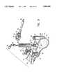
- FIG. 2is an exploded pictorial perspective view, partially schematic, of the alignment system of the present invention at the distal end of a femur;
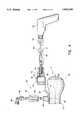
- FIG. 3is a pictorial perspective view, similar to FIG. 2, but only partially exploded;
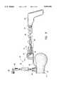
- FIGS. 4 and 5are enlarged fragmentary side elevational views, partially in cross-section, of a portion of the alignment system illustrating the method of the present invention
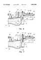
- FIG. 6is an enlarged fragmentary side elevational view similar to FIGS. 4 and 5, but showing the location of guides at the distal end of the femur;
- FIG. 7is a side elevational view similar to FIG. 6, with an alternate guide.
- the femur of a supine patientis illustrated schematically at 10 and is seen to include a femoral head 12 and a distal end 14 at the knee K of the patient.
- the femur 10is constrained for rotation about the femoral head 12 and the mechanical axis 16 of the femur 10 passes through the center of rotation 18 of the femoral head 12 and the center 20 of the knee K of the patient.
- the location of the mechanical axis 16can be determined by freely suspending the leg of the patient to permit free rotation of the femoral head 12 and then applying a tensile force at the center 20 of the knee to rotate the femur 10 until the mechanical axis 16 is aligned with the direction of the tensile force. Then, the direction of the tensile force serves as an indication of the location of the center of rotation 18 and the direction of the mechanical axis 16 relative to the center 20 of the knee, thereby locating the mechanical axis 16 and enabling that location to be used for the proper placement of cutting guides at the knee.
- the present inventioneliminates the effect of external forces in the determination of the direction of the mechanical axis 16 by eliminating the requirement for rotating the femur 10 in response to an applied tensile force and relying, rather, on the fact that the femur 10 will not rotate when a force is applied to the femur in a direction aligned with the mechanical axis 16 so as to pass through the center of rotation 18. Accordingly, in the method and apparatus of the present invention, the leg of the patient is partially suspended, at the knee K, so as to balance external forces at the knee and locate the knee at an equilibrium, or suspended, position.
- a forceillustrated in the form of a tensile force F, is applied to the distal femur 26, at the knee K, at a predetermined location relative to the mechanical axis 16.
- Force Fis moved so as to be applied in directions parallel to the coronal plane, as illustrated in phantom as well as in full lines in FIG. 1, and any deviations in the location of the knee K from the suspended position, that is, any movements of the knee K within the coronal plane to either side of the suspended position while force F is applied to the knee, are observed until force F is oriented in a direction wherein the knee is undeflected from the suspended position and remains stationary at the suspended position.
- the direction of force Fwhich produces no deflection of the knee from the suspended position, as illustrated in full lines in FIG.
- FIGS. 2 and 3distal femur 26 is shown being prepared for the determination of the direction and location of the mechanical axis of the femur 10 and the subsequent implant of a femoral knee prosthesis not shown).
- Apparatus constructed in accordance with the present inventionis illustrated generally at 30 and is seen to include securing means shown in the form of a femoral clamp 32 having clamping jaws 34 which grip the femur 10 to secure the femoral clamp 32 upon the exposed femur 10.
- An anterior reference member in the form of a bearing holder 36includes an anterior reference bar 38 having an anterior reference surface 40 which is seated against the anterior cortex 42 of distal femur 26 when the anterior reference bar 38 is engaged with the femoral clamp 32, as seen in FIG. 3.
- anterior reference bar 38includes a ramp 44 providing a wedge-shaped proximal end for facilitating insertion of the anterior reference bar 38 into a complementary channel 46 in the femoral clamp 32 and assuring direct contact between the anterior reference surface 40 and the anterior cortex 42.
- Fernoral clamp 32includes a clamping screw 48 which is tightened to clamp the anterior reference bar 38 in place, as seen in FIG. 3. Once clamped in place, with anterior reference surface 40 in intimate, fixed contact with anterior cortex 42, anterior reference bar 38 will be aligned with the sagittal component of the mechanical axis of femur 10.
- a stud 50is affixed at the distal end of the bearing holder 36 and projects in an anterior direction, normal to the coronal plane, to receive a bearing 52 placed over the stud 50 and secured to the stud 50 against rotation on the stud 50.
- stud 50includes opposite flats 54 and bearing 52 includes a central opening 56 having a complementary configuration for securing the bearing 52 on the stud 50.
- a retainer screw 58is affixed to the stud 50 to hold the bearing 52 in place on the stud 50 so that the bearing 52 provides a cylindrical bearing surface 60 extending in the anterior direction along an axis 62 normal to the coronal plane.
- An intercondylar post 64includes a clip 66 which is snapped over the bearing 52 to secure the intercondylar post 64 to the bearing holder 36 with the intercondylar post 64 depending from the bearing holder 36, normal to the coronal plane, in the posterior direction.
- bearing 52Prior to clamping the bearing holder 36 in place, as seen in FIG. 3, bearing 52 is secured on stud 50 and intercondylar post 64 is clipped to bearing 52. Then, the proximal end of the anterior reference bar 38 is engaged with the femoral clamp 32, with the intercondylar post 64 assisting in the proper positioning of the bearing holder 36, by virtue of the placement of the intercondylar post 64 between the condyles 68 of the distal femur 26 and perpendicular to the coronal plane.
- an alignment member in the form of an elongate alignment rod 70is coupled with a collar 72 by means of a threaded coupling 74 and includes a pointed tip 76 which initially is recessed with respect to a bore 78 in the collar 72.
- Bore 78is complementary to the cylindrical bearing surface 60 of bearing 52 so that alignment rod 70 can be coupled with bearing 52 by slipping collar 72 over bearing 52, with collar 72 journaled for rotation on bearing 52, to enable pivotal movement of the alignment rod 70 about axis 62.
- the leg of the patientis partially suspended by connecting the bearing holder 36 to a support arm 80 located above the femur 10, as seen in FIGS. 3 and 4.
- a vertical alignment and suspension deviceshown somewhat schematically at 82, is connected between the bearing holder 36 and the support arm 80, as by suspension couplings 84 and 86.
- Support arm 80is a part of a positioning system which may be manipulated by the surgeon to swing the support arm 80 directly over the femur 10 so as to facilitate attachment of the vertical alignment and suspension device 82 at couplings 84 and 86, and suspension of the patient's leg. Then the patient's leg is elevated until the weight of the leg is substantially supported by the support arm 80.
- FIG. 4In which suspended position the vertical alignment and suspension device 82 indicates that the line of suspension 90 is truly vertical with respect to gravity. In this equilibrium position of the knee, all external forces on the knee are balanced, and the knee remains essentially stationary.
- One positioning system currently available for use in positioning support arm 80is known as the ENDEX endoscopy positioning system sold by Andronic Devices Ltd. of Richmond, B.C., Canada.
- Vertical alignment and suspension device 82may be in the form of a simple mechanical plumb bob arrangement which provides a visual indication of plumb, that is, vertical alignment along the line of suspension 90, or may be in the form of an electronic plumb indicator.
- a powered surgical drill 92subsequently is coupled to the distal end of the alignment rod 70, through a force indicator 94, by means of a coupling arrangement shown in the form of a hook 96, affixed to the surgical drill 92 for rotation by the surgical drill 92, and passed through an eye 98 at the distal end of alignment rod 70.
- the surgeonthen pulls upon the surgical drill 92, in the direction illustrated, to apply a force along the alignment rod 70, which force is transmitted to the bearing 52 and the bearing holder 36, and observes the force indicator 94 to gage the amount of force exerted.
- a tensile forceof at least about ten pounds is applied to alignment rod 70 to establish force F.
- Force Fthus is applied to the femur 10 at the predetermined location established by the location and orientation of bearing 52 by means of the surgical drill 92 coupled to the knee K through the alignment rod 70, the force indicator 94, the hook 96 and the eye 98, and pulled upon by the surgeon to establish the tensile force.
- the angular direction of the force Fis changed by the surgeon, in directions parallel to the coronal plane, by angular pivotal movement of the alignment rod 70 about axis 62, with collar 72 journaled on bearing surface 60 of bearing 52 serving as means for directing the applied force F, to align force F so that the knee K is maintained stationary at the suspended position, and is undeflected from the suspended position, as observed by indications provided by the vertical alignment and suspension device 82, while force F is applied to the femur 10 at the knee K.
- the alignment rod 70Upon reaching the angular position of alignment rod 70 where the knee K remains undeflected from the suspension position while force F is applied to the knee K, the alignment rod 70 is locked in place by actuating the powered surgical drill 92 to rotate alignment rod 70 about the longitudinal axis of the alignment rod 70, as indicated by the arrow in FIG. 5. Such rotation of the alignment rod 70 advances the pointed tip 76 of the alignment rod 70, by means of the thread ed coupling 74, to embed the pointed tip 76 in the bearing 52, as seen in FIG.
- bearing 52preferably is constructed of a synthetic polymeric material having sufficient lubricity to facilitate the necessary angular movements of the alignment rod 70, as described above, while enabling a fixed connection through the use of pointed tip 76.
- alignment rod 70With the alignment rod 70 affixed on the bearing 52, as described above, the direction in which the alignment rod 70 extends is parallel with the mechanical axis 16 of femur 10 and the direction of the mechanical axis 16 is determined. Further, since alignment rod 70 is parallel with the mechanical axis 16, alignment rod 70 now is available for use in locating cutting guides for making the cuts necessary to prepare the distal femur 26 for the reception of the femoral knee prosthesis to be implanted. Turning now to FIG.
- the surgical drill 92 and the force indicator 94are removed from the alignment rod 70, the vertical alignment and suspension device 82 is uncoupled from the bearing holder 36 and the support arm 80, and the support arm 80 is affixed directly to the bearing holder 36 so that the femur 10 is held in place, essentially rigidly, by the support arm 80.
- the alignment rod 70now is available to receive a distal femoral condyle locator 100 which is slipped over the distal end of the alignment rod 70 and translated along the alignment rod 70 until the femoral condyle locator 100 engages the distal end of the femur 10.
- the femoral condyle locator 100includes a sleeve 102 for sliding along the alignment rod 70 and a locator surface 104 which is maintained perpendicular to alignment rod 70 by the engagement of the sleeve 102 with the alignment rod 70.
- femoral condyle locator 100is secured in place by a set screw 106.
- a femoral drill guide 110then is mounted upon the femoral condyle locator 100 by engaging pins 112 through the femoral drill guide 110 and into corresponding holes 114 in the femoral condyle locator 100 to lock the femoral drill guide 110 in place.
- Femoral drill guide 110includes a plurality of drill alignment holes 118, any matched pair of which may be selected by the surgeon for drilling corresponding locator holes 120 in the femur 10.
- locator holes 120are placed in appropriate position relative to the mechanical axis 16 of the femur 10 for the reception of standard cutting guides for the resection of the distal femur 26.
- Apparatus 30is removed from distal femur 26 by removing the femoral drill guide 110 from the femoral condyle locator 100, then removing the femoral condyle locator 100 from the alignment rod 70, then uncoupling the alignment rod 70 from the bearing 52, uncoupling the support arm 80 from the bearing holder 36, loosening the clamping screw 48 to detach the bearing holder 36 from the femoral clamp 32 and then removing the femoral clamp 32 from the femur 10. Locator holes 120 are then available for use in connection with conventional cutting guides.
- a distal femoral resection guide 130is located on the femoral condyle locator 100, as by pins 132 extending through the femoral resection guide 130 to enter a corresponding selected set of holes 114 in the femoral condyle locator 100.
- the distal femoral resection guide 130then is locked to the alignment rod 70, by virtue of pins 132 engage d with holes 114 in the femoral condyle locator 110 which is secured in place by set screw 106.
- Slots 134are provided in the distal femoral resection guide 130 in position to guide a cutting instrument, such as a saw, for executing distal femoral cuts 136.
- Apparatus 30then is removed from the femur 10, as described above, and resection of the distal femur 26 is completed in a conventional manner, utilizing the distal femoral surfaces 138 established by femoral cuts 136.
- the present inventionattains the several objects and advantages summarized above, namely: Enables accurate location of the direction of the mechanical axis of the femur interoperatively, without invading the medullary canal and without the necessity for surgical intervention beyond that already required for access to the knee being replaced; provides a relatively simple procedure capable of being performed quickly just prior to preparing the femur for distal cuts; attains a high degree of accuracy with minimal procedural steps and apparatus; enables a direct determination of the direction of the mechanical axis of the femur without reliance upon visual estimation or interpretation; provides apparatus capable of long-term reliable performance.
Landscapes
- Health & Medical Sciences (AREA)
- Surgery (AREA)
- Life Sciences & Earth Sciences (AREA)
- Biomedical Technology (AREA)
- Medical Informatics (AREA)
- Oral & Maxillofacial Surgery (AREA)
- Nuclear Medicine, Radiotherapy & Molecular Imaging (AREA)
- Transplantation (AREA)
- Physical Education & Sports Medicine (AREA)
- Engineering & Computer Science (AREA)
- Orthopedic Medicine & Surgery (AREA)
- Heart & Thoracic Surgery (AREA)
- Dentistry (AREA)
- Molecular Biology (AREA)
- Animal Behavior & Ethology (AREA)
- General Health & Medical Sciences (AREA)
- Public Health (AREA)
- Veterinary Medicine (AREA)
- Surgical Instruments (AREA)
- Prostheses (AREA)
Abstract
Description
Claims (14)
Priority Applications (7)
| Application Number | Priority Date | Filing Date | Title |
|---|---|---|---|
| US08/199,069US5601566A (en) | 1994-02-22 | 1994-02-22 | Method and apparatus for the alignment of a femoral knee prosthesis |
| CA002142083ACA2142083C (en) | 1994-02-22 | 1995-02-08 | Method and apparatus for the alignment of a femoral knee prosthesis |
| AU12280/95AAU696813B2 (en) | 1994-02-22 | 1995-02-15 | Method and apparatus for the alignment of a femoral knee prosthesis |
| DE69529361TDE69529361T2 (en) | 1994-02-22 | 1995-02-17 | Device for determining the direction of the mechanical axis of a femur |
| EP95301039AEP0677274B1 (en) | 1994-02-22 | 1995-02-17 | Apparatus for determining the direction of the mechanical axis of a femur |
| JP05677395AJP3364732B2 (en) | 1994-02-22 | 1995-02-22 | Device for orienting the mechanical axis of the femur relative to the knee |
| US08/773,193US5690638A (en) | 1994-02-22 | 1996-12-27 | Method and apparatus for the alignment of a femoral knee posthesis |
Applications Claiming Priority (1)
| Application Number | Priority Date | Filing Date | Title |
|---|---|---|---|
| US08/199,069US5601566A (en) | 1994-02-22 | 1994-02-22 | Method and apparatus for the alignment of a femoral knee prosthesis |
Related Child Applications (1)
| Application Number | Title | Priority Date | Filing Date |
|---|---|---|---|
| US08/773,193DivisionUS5690638A (en) | 1994-02-22 | 1996-12-27 | Method and apparatus for the alignment of a femoral knee posthesis |
Publications (1)
| Publication Number | Publication Date |
|---|---|
| US5601566Atrue US5601566A (en) | 1997-02-11 |
Family
ID=22736086
Family Applications (2)
| Application Number | Title | Priority Date | Filing Date |
|---|---|---|---|
| US08/199,069Expired - LifetimeUS5601566A (en) | 1994-02-22 | 1994-02-22 | Method and apparatus for the alignment of a femoral knee prosthesis |
| US08/773,193Expired - LifetimeUS5690638A (en) | 1994-02-22 | 1996-12-27 | Method and apparatus for the alignment of a femoral knee posthesis |
Family Applications After (1)
| Application Number | Title | Priority Date | Filing Date |
|---|---|---|---|
| US08/773,193Expired - LifetimeUS5690638A (en) | 1994-02-22 | 1996-12-27 | Method and apparatus for the alignment of a femoral knee posthesis |
Country Status (6)
| Country | Link |
|---|---|
| US (2) | US5601566A (en) |
| EP (1) | EP0677274B1 (en) |
| JP (1) | JP3364732B2 (en) |
| AU (1) | AU696813B2 (en) |
| CA (1) | CA2142083C (en) |
| DE (1) | DE69529361T2 (en) |
Cited By (23)
| Publication number | Priority date | Publication date | Assignee | Title |
|---|---|---|---|---|
| EP0839501A2 (en) | 1996-10-30 | 1998-05-06 | Osteonics Corp. | Apparatus and method for the alignment of a total knee prosthesis |
| US20030181920A1 (en)* | 2002-03-25 | 2003-09-25 | Hawkins J. Riley | Device for determining distance between two points in a surgical site |
| US20030216742A1 (en)* | 2002-02-13 | 2003-11-20 | Merrick Wetzler | Surgical drill guide |
| US6702824B2 (en) | 1999-09-10 | 2004-03-09 | Depuy Orthopaedics, Inc. | Prosthesis positioning apparatus |
| US20050102032A1 (en)* | 2003-11-07 | 2005-05-12 | University Of Vermont And State Agricultural College | Knee joint prosthesis with a femoral component which links the tibiofemoral axis of rotation with the patellofemoral axis of rotation |
| US20050113720A1 (en)* | 1998-11-10 | 2005-05-26 | Philippe Cinquin | Method and device for determining the center of a joint |
| US20050149040A1 (en)* | 1994-09-02 | 2005-07-07 | Haines Timothy G. | Methods and apparatus for orthopedic surgical navigation and alignment |
| US20060015116A1 (en)* | 2004-01-14 | 2006-01-19 | Haines Timothy G | Methods and apparatus for improved drilling and milling tools for resection |
| US20060015109A1 (en)* | 2004-01-14 | 2006-01-19 | Haines Timothy G | Methods and apparatus for improved cutting tools for resection |
| US20060030944A1 (en)* | 2004-01-14 | 2006-02-09 | Haines Timothy G | Methods and apparatus for enhanced retention of prosthetic implants |
| US20060155380A1 (en)* | 2002-10-23 | 2006-07-13 | Mako Surgical Corporation | Modular femoral component for a total knee joint replacement for minimally invasive implantation |
| US20060200156A1 (en)* | 2005-01-05 | 2006-09-07 | Jamal Taha | Spinal docking system, spinal docking device, and methods of spinal stabilization |
| US20060241637A1 (en)* | 2002-11-27 | 2006-10-26 | Zimmer Technology, Inc. | Method and apparatus for achieving correct limb alignment in unicondylar knee arthroplasty |
| US20080154270A1 (en)* | 2001-03-05 | 2008-06-26 | Haines Timothy G | Methods and apparatus for knee arthroplasty |
| US20080306487A1 (en)* | 2007-06-06 | 2008-12-11 | Rickey Hart | Drill Guide And Method For Placing A Fixation Device Hole |
| US20090082773A1 (en)* | 2004-01-14 | 2009-03-26 | Haines Timothy G | Method and apparatus for wireplasty bone resection |
| US8425522B2 (en) | 2000-01-14 | 2013-04-23 | Bonutti Skeletal Innovations Llc | Joint replacement method |
| US8603095B2 (en) | 1994-09-02 | 2013-12-10 | Puget Bio Ventures LLC | Apparatuses for femoral and tibial resection |
| US8623030B2 (en) | 2001-08-28 | 2014-01-07 | Bonutti Skeletal Innovations Llc | Robotic arthroplasty system including navigation |
| US20170148351A1 (en)* | 2015-11-20 | 2017-05-25 | United Arab Emirates University | Smart drill guide device for muscle training of hand drilling operations |
| US9707086B2 (en) | 2013-02-08 | 2017-07-18 | Orthopaedic International, Inc. | Total knee arthroplasty methods, systems, and instruments |
| US10828046B2 (en) | 2007-09-30 | 2020-11-10 | DePuy Synthes Products, Inc. | Apparatus and method for fabricating a customized patient-specific orthopaedic instrument |
| US11051829B2 (en) | 2018-06-26 | 2021-07-06 | DePuy Synthes Products, Inc. | Customized patient-specific orthopaedic surgical instrument |
Families Citing this family (17)
| Publication number | Priority date | Publication date | Assignee | Title |
|---|---|---|---|---|
| US7214232B2 (en)* | 1999-07-23 | 2007-05-08 | Ethicon, Inc. | Graft fixation device |
| ES2254519T3 (en)* | 2000-08-31 | 2006-06-16 | Plus Orthopedics Ag | DETERMINATION DEVICE OF A LOADING AXLE OF AN EXTREMITY. |
| US6723102B2 (en)* | 2001-06-14 | 2004-04-20 | Alexandria Research Technologies, Llc | Apparatus and method for minimally invasive total joint replacement |
| US6482209B1 (en) | 2001-06-14 | 2002-11-19 | Gerard A. Engh | Apparatus and method for sculpting the surface of a joint |
| JP2003144454A (en)* | 2001-11-16 | 2003-05-20 | Yoshio Koga | Joint operation support information computing method, joint operation support information computing program, and joint operation support information computing system |
| DE10306793A1 (en)* | 2002-05-21 | 2003-12-04 | Plus Endoprothetik Ag Rotkreuz | Arrangement and method for the intraoperative determination of the position of a joint replacement implant |
| US20050070897A1 (en)* | 2003-09-29 | 2005-03-31 | Petersen Thomas D. | Laser triangulation of the femoral head for total knee arthroplasty alignment instruments and surgical method |
| EP1561431B1 (en)* | 2004-02-03 | 2009-08-12 | BrainLAB AG | Device for determining the position of a cutting guide |
| GB0411487D0 (en)* | 2004-05-22 | 2004-06-23 | Depuy Int Ltd | Surgical jig |
| US8187279B2 (en) | 2006-10-31 | 2012-05-29 | Depuy Products, Inc. | Surgical instrument system with ball and socket support |
| US7947862B2 (en) | 2006-10-31 | 2011-05-24 | Depuy Products, Inc. | Limb stabilizing system for arthroplasty |
| US20080109085A1 (en)* | 2006-11-03 | 2008-05-08 | Howmedica Osteonics Corp. | Method and apparatus for hip femoral resurfacing tooling |
| DE102007024708B4 (en)* | 2007-05-25 | 2016-11-10 | Klaus Radermacher | Device and method for determining the mechanical leg axis of a femur |
| US8795282B2 (en)* | 2009-01-29 | 2014-08-05 | Zimmer, Inc. | Apparatus and method for the extramedullary location of the mechanical axis of a femur |
| USD646388S1 (en)* | 2010-05-28 | 2011-10-04 | Zimmer, Inc. | Extramedullary rod alignment adapter |
| JP4652481B1 (en)* | 2010-07-29 | 2011-03-16 | 浩一 金粕 | Femoral head center position identification device |
| CN114451953B (en)* | 2022-02-10 | 2024-08-09 | 纳通生物科技(北京)有限公司 | Personalized positioning bone cutter for knee joint |
Citations (17)
| Publication number | Priority date | Publication date | Assignee | Title |
|---|---|---|---|---|
| US4407277A (en)* | 1980-10-27 | 1983-10-04 | Ellison Arthur E | Surgical apparatus |
| US4467801A (en)* | 1983-03-09 | 1984-08-28 | Wright Manufacturing Company | Method and apparatus for shaping a proximal tibial surface |
| US4474177A (en)* | 1983-03-09 | 1984-10-02 | Wright Manufacturing Company | Method and apparatus for shaping a distal femoral surface |
| US4524766A (en)* | 1982-01-07 | 1985-06-25 | Petersen Thomas D | Surgical knee alignment method and system |
| US4571834A (en)* | 1984-02-17 | 1986-02-25 | Orthotronics Limited Partnership | Knee laxity evaluator and motion module/digitizer arrangement |
| US4574794A (en)* | 1984-06-01 | 1986-03-11 | Queen's University At Kingston | Orthopaedic bone cutting jig and alignment device |
| US4773407A (en)* | 1986-07-23 | 1988-09-27 | Thomas Petersen | Method and instruments for resection of the distal femur |
| US4807618A (en)* | 1987-01-23 | 1989-02-28 | Andronic Devices, Ltd. | Patient limb positioning apparatus |
| EP0326768A2 (en)* | 1988-02-01 | 1989-08-09 | Faro Medical Technologies Inc. | Computer-aided surgery apparatus |
| US4935023A (en)* | 1989-01-09 | 1990-06-19 | Dow Corning Wright | Femoral surface shaping guide for knee implants |
| US5002545A (en)* | 1989-01-30 | 1991-03-26 | Dow Corning Wright Corporation | Tibial surface shaping guide for knee implants |
| US5007912A (en)* | 1990-05-30 | 1991-04-16 | Albrektsson Bjoern | Arrangement for fixing a knee-joint in defined positions and for positional control of instruments for replacing the knee-joint with a prosthesis |
| US5154717A (en)* | 1988-04-26 | 1992-10-13 | The Board Of Regents Of The University Of Washington | Robot-aided system for surgery |
| US5201325A (en)* | 1989-09-01 | 1993-04-13 | Andronic Devices Ltd. | Advanced surgical retractor |
| US5257998A (en)* | 1989-09-20 | 1993-11-02 | Mitaka Kohki Co., Ltd. | Medical three-dimensional locating apparatus |
| USRE34762E (en)* | 1988-09-19 | 1994-10-18 | Goble; E. Marlowe | Procedure for verifying isometric ligament positioning |
| US5520694A (en)* | 1993-06-21 | 1996-05-28 | Dance; Mark N. | Apparatus and method for aligning knee prostheses |
Family Cites Families (3)
| Publication number | Priority date | Publication date | Assignee | Title |
|---|---|---|---|---|
| FR2587198A1 (en)* | 1985-09-13 | 1987-03-20 | Aubaniac Jean | METHOD FOR IMPLEMENTING KNEE PROSTHESIS AND IMPLEMENTING APPARATUS |
| US4841975A (en)* | 1987-04-15 | 1989-06-27 | Cemax, Inc. | Preoperative planning of bone cuts and joint replacement using radiant energy scan imaging |
| US4938762A (en)* | 1987-12-16 | 1990-07-03 | Protek Ag | Reference system for implantation of condylar total knee prostheses |
- 1994
- 1994-02-22USUS08/199,069patent/US5601566A/ennot_activeExpired - Lifetime
- 1995
- 1995-02-08CACA002142083Apatent/CA2142083C/ennot_activeExpired - Fee Related
- 1995-02-15AUAU12280/95Apatent/AU696813B2/ennot_activeCeased
- 1995-02-17DEDE69529361Tpatent/DE69529361T2/ennot_activeExpired - Lifetime
- 1995-02-17EPEP95301039Apatent/EP0677274B1/ennot_activeExpired - Lifetime
- 1995-02-22JPJP05677395Apatent/JP3364732B2/ennot_activeExpired - Fee Related
- 1996
- 1996-12-27USUS08/773,193patent/US5690638A/ennot_activeExpired - Lifetime
Patent Citations (19)
| Publication number | Priority date | Publication date | Assignee | Title |
|---|---|---|---|---|
| US4407277A (en)* | 1980-10-27 | 1983-10-04 | Ellison Arthur E | Surgical apparatus |
| US4524766A (en)* | 1982-01-07 | 1985-06-25 | Petersen Thomas D | Surgical knee alignment method and system |
| US4467801A (en)* | 1983-03-09 | 1984-08-28 | Wright Manufacturing Company | Method and apparatus for shaping a proximal tibial surface |
| US4474177A (en)* | 1983-03-09 | 1984-10-02 | Wright Manufacturing Company | Method and apparatus for shaping a distal femoral surface |
| US4571834A (en)* | 1984-02-17 | 1986-02-25 | Orthotronics Limited Partnership | Knee laxity evaluator and motion module/digitizer arrangement |
| US4574794A (en)* | 1984-06-01 | 1986-03-11 | Queen's University At Kingston | Orthopaedic bone cutting jig and alignment device |
| US4773407A (en)* | 1986-07-23 | 1988-09-27 | Thomas Petersen | Method and instruments for resection of the distal femur |
| CA1271102A (en)* | 1987-01-23 | 1990-07-03 | Andronic Devices Ltd. | Patient limb positioning apparatus |
| US4807618A (en)* | 1987-01-23 | 1989-02-28 | Andronic Devices, Ltd. | Patient limb positioning apparatus |
| US5104103A (en)* | 1987-01-23 | 1992-04-14 | Andronic Devices, Ltd. | Apparatus for patient limb positioning |
| EP0326768A2 (en)* | 1988-02-01 | 1989-08-09 | Faro Medical Technologies Inc. | Computer-aided surgery apparatus |
| US5154717A (en)* | 1988-04-26 | 1992-10-13 | The Board Of Regents Of The University Of Washington | Robot-aided system for surgery |
| USRE34762E (en)* | 1988-09-19 | 1994-10-18 | Goble; E. Marlowe | Procedure for verifying isometric ligament positioning |
| US4935023A (en)* | 1989-01-09 | 1990-06-19 | Dow Corning Wright | Femoral surface shaping guide for knee implants |
| US5002545A (en)* | 1989-01-30 | 1991-03-26 | Dow Corning Wright Corporation | Tibial surface shaping guide for knee implants |
| US5201325A (en)* | 1989-09-01 | 1993-04-13 | Andronic Devices Ltd. | Advanced surgical retractor |
| US5257998A (en)* | 1989-09-20 | 1993-11-02 | Mitaka Kohki Co., Ltd. | Medical three-dimensional locating apparatus |
| US5007912A (en)* | 1990-05-30 | 1991-04-16 | Albrektsson Bjoern | Arrangement for fixing a knee-joint in defined positions and for positional control of instruments for replacing the knee-joint with a prosthesis |
| US5520694A (en)* | 1993-06-21 | 1996-05-28 | Dance; Mark N. | Apparatus and method for aligning knee prostheses |
Cited By (72)
| Publication number | Priority date | Publication date | Assignee | Title |
|---|---|---|---|---|
| US7967822B2 (en) | 1994-09-02 | 2011-06-28 | Hudson Surgical Design, Inc. | Methods and apparatus for orthopedic implants |
| US9066804B2 (en) | 1994-09-02 | 2015-06-30 | Puget Bioventures Llc | Method and apparatus for femoral and tibial resection |
| US8603095B2 (en) | 1994-09-02 | 2013-12-10 | Puget Bio Ventures LLC | Apparatuses for femoral and tibial resection |
| US20050149040A1 (en)* | 1994-09-02 | 2005-07-07 | Haines Timothy G. | Methods and apparatus for orthopedic surgical navigation and alignment |
| US20050149039A1 (en)* | 1994-09-02 | 2005-07-07 | Haines Timothy G. | Methods and apparatus for orthopedic implants |
| EP0839501A2 (en) | 1996-10-30 | 1998-05-06 | Osteonics Corp. | Apparatus and method for the alignment of a total knee prosthesis |
| EP0839501B1 (en)* | 1996-10-30 | 2003-03-12 | Osteonics Corp. | Apparatus and method for the alignment of a total knee prosthesis |
| US20050113720A1 (en)* | 1998-11-10 | 2005-05-26 | Philippe Cinquin | Method and device for determining the center of a joint |
| US6702824B2 (en) | 1999-09-10 | 2004-03-09 | Depuy Orthopaedics, Inc. | Prosthesis positioning apparatus |
| US9101443B2 (en) | 2000-01-14 | 2015-08-11 | Bonutti Skeletal Innovations Llc | Methods for robotic arthroplasty |
| US8425522B2 (en) | 2000-01-14 | 2013-04-23 | Bonutti Skeletal Innovations Llc | Joint replacement method |
| US9795394B2 (en) | 2000-01-14 | 2017-10-24 | Bonutti Skeletal Innovations Llc | Method for placing implant using robotic system |
| US8632552B2 (en) | 2000-01-14 | 2014-01-21 | Bonutti Skeletal Innovations Llc | Method of preparing a femur and tibia in knee arthroplasty |
| US8784495B2 (en) | 2000-01-14 | 2014-07-22 | Bonutti Skeletal Innovations Llc | Segmental knee arthroplasty |
| US9192459B2 (en) | 2000-01-14 | 2015-11-24 | Bonutti Skeletal Innovations Llc | Method of performing total knee arthroplasty |
| US8062377B2 (en) | 2001-03-05 | 2011-11-22 | Hudson Surgical Design, Inc. | Methods and apparatus for knee arthroplasty |
| US9421022B2 (en) | 2001-03-05 | 2016-08-23 | Puget Bioventures Llc | Method and apparatus for total knee arthroplasty |
| US9192391B2 (en) | 2001-03-05 | 2015-11-24 | Puget Bioventures Llc | Method for minimally invasive total knee arthroplasty |
| US7935151B2 (en) | 2001-03-05 | 2011-05-03 | Hudson Surgical Design, Inc. | Femoral prosthetic implant |
| US8430932B2 (en) | 2001-03-05 | 2013-04-30 | Puget Bio Ventures LLC | Femoral prosthetic implant |
| US20080154270A1 (en)* | 2001-03-05 | 2008-06-26 | Haines Timothy G | Methods and apparatus for knee arthroplasty |
| US20100185203A1 (en)* | 2001-03-05 | 2010-07-22 | Hudson Surgical Design, Inc. | Femoral prosthetic implant |
| US20100100192A1 (en)* | 2001-03-05 | 2010-04-22 | Haines Timothy G | Femoral prosthetic implant |
| US8088167B2 (en) | 2001-03-05 | 2012-01-03 | Hudson Surgical Design, Inc. | Femoral prosthetic implant |
| US8840629B2 (en) | 2001-08-28 | 2014-09-23 | Bonutti Skeletal Innovations Llc | Robotic arthroplasty system including navigation |
| US8858557B2 (en) | 2001-08-28 | 2014-10-14 | Bonutti Skeletal Innovations Llc | Method of preparing a femur and tibia in knee arthroplasty |
| US9060797B2 (en) | 2001-08-28 | 2015-06-23 | Bonutti Skeletal Innovations Llc | Method of preparing a femur and tibia in knee arthroplasty |
| US8834490B2 (en) | 2001-08-28 | 2014-09-16 | Bonutti Skeletal Innovations Llc | Method for robotic arthroplasty using navigation |
| US10231739B1 (en) | 2001-08-28 | 2019-03-19 | Bonutti Skeletal Innovations Llc | System and method for robotic surgery |
| US8641726B2 (en) | 2001-08-28 | 2014-02-04 | Bonutti Skeletal Innovations Llc | Method for robotic arthroplasty using navigation |
| US9763683B2 (en) | 2001-08-28 | 2017-09-19 | Bonutti Skeletal Innovations Llc | Method for performing surgical procedures using optical cutting guides |
| US10321918B2 (en) | 2001-08-28 | 2019-06-18 | Bonutti Skeletal Innovations Llc | Methods for robotic surgery using a cannula |
| US10470780B2 (en) | 2001-08-28 | 2019-11-12 | Bonutti Skeletal Innovations Llc | Systems and methods for ligament balancing in robotic surgery |
| US8623030B2 (en) | 2001-08-28 | 2014-01-07 | Bonutti Skeletal Innovations Llc | Robotic arthroplasty system including navigation |
| US20050177171A1 (en)* | 2002-02-13 | 2005-08-11 | Merrick Wetzler | Surgical drill guide |
| US7575578B2 (en) | 2002-02-13 | 2009-08-18 | Karl Storz Gmbh & Co. Kg | Surgical drill guide |
| US7192432B2 (en) | 2002-02-13 | 2007-03-20 | Karl Storz Gmbh & Co. Kg | Surgical drill guide |
| US20030216742A1 (en)* | 2002-02-13 | 2003-11-20 | Merrick Wetzler | Surgical drill guide |
| US7166112B2 (en)* | 2002-03-25 | 2007-01-23 | Depuy Spine, Inc. | Device for determining distance between two points in a surgical site |
| US20030181920A1 (en)* | 2002-03-25 | 2003-09-25 | Hawkins J. Riley | Device for determining distance between two points in a surgical site |
| US7799084B2 (en) | 2002-10-23 | 2010-09-21 | Mako Surgical Corp. | Modular femoral component for a total knee joint replacement for minimally invasive implantation |
| US20060155380A1 (en)* | 2002-10-23 | 2006-07-13 | Mako Surgical Corporation | Modular femoral component for a total knee joint replacement for minimally invasive implantation |
| US8454616B2 (en) | 2002-11-27 | 2013-06-04 | Zimmer, Inc. | Method and apparatus for achieving correct limb alignment in unicondylar knee arthroplasty |
| US20060241637A1 (en)* | 2002-11-27 | 2006-10-26 | Zimmer Technology, Inc. | Method and apparatus for achieving correct limb alignment in unicondylar knee arthroplasty |
| US20060247647A1 (en)* | 2002-11-27 | 2006-11-02 | Zimmer Technology, Inc. | Method and apparatus for achieving correct limb alignment in unicondylar knee arthroplasty |
| US7842039B2 (en)* | 2002-11-27 | 2010-11-30 | Zimmer Technology, Inc. | Method and apparatus for achieving correct limb alignment in unicondylar knee arthroplasty |
| US7387644B2 (en) | 2003-11-07 | 2008-06-17 | University Of Vermont And State Agricultural College | Knee joint prosthesis with a femoral component which links the tibiofemoral axis of rotation with the patellofemoral axis of rotation |
| US20050102032A1 (en)* | 2003-11-07 | 2005-05-12 | University Of Vermont And State Agricultural College | Knee joint prosthesis with a femoral component which links the tibiofemoral axis of rotation with the patellofemoral axis of rotation |
| US8021368B2 (en) | 2004-01-14 | 2011-09-20 | Hudson Surgical Design, Inc. | Methods and apparatus for improved cutting tools for resection |
| US20060015116A1 (en)* | 2004-01-14 | 2006-01-19 | Haines Timothy G | Methods and apparatus for improved drilling and milling tools for resection |
| US20090082773A1 (en)* | 2004-01-14 | 2009-03-26 | Haines Timothy G | Method and apparatus for wireplasty bone resection |
| US9814539B2 (en) | 2004-01-14 | 2017-11-14 | Puget Bioventures Llc | Methods and apparatus for conformable prosthetic implants |
| US8740906B2 (en) | 2004-01-14 | 2014-06-03 | Hudson Surgical Design, Inc. | Method and apparatus for wireplasty bone resection |
| US20060030944A1 (en)* | 2004-01-14 | 2006-02-09 | Haines Timothy G | Methods and apparatus for enhanced retention of prosthetic implants |
| US8114083B2 (en) | 2004-01-14 | 2012-02-14 | Hudson Surgical Design, Inc. | Methods and apparatus for improved drilling and milling tools for resection |
| US8287545B2 (en) | 2004-01-14 | 2012-10-16 | Hudson Surgical Design, Inc. | Methods and apparatus for enhanced retention of prosthetic implants |
| US20060015109A1 (en)* | 2004-01-14 | 2006-01-19 | Haines Timothy G | Methods and apparatus for improved cutting tools for resection |
| US8353914B2 (en) | 2004-02-02 | 2013-01-15 | Hudson Surgical Design, Inc. | Methods and apparatus for improved profile based resection |
| US20060200156A1 (en)* | 2005-01-05 | 2006-09-07 | Jamal Taha | Spinal docking system, spinal docking device, and methods of spinal stabilization |
| US20080306487A1 (en)* | 2007-06-06 | 2008-12-11 | Rickey Hart | Drill Guide And Method For Placing A Fixation Device Hole |
| US20090287219A1 (en)* | 2007-06-06 | 2009-11-19 | Rickey Hart | Drill Guide And Method For Placing A Fixation Device Hole |
| US7815646B2 (en) | 2007-06-06 | 2010-10-19 | Karl Storz Gmbh & Co. Kg | Drill guide and method for placing a fixation device hole |
| US7927340B2 (en) | 2007-06-06 | 2011-04-19 | Karl Storz Gmbh & Co. Kg | Drill guide and method for placing a fixation device hole |
| US11696768B2 (en) | 2007-09-30 | 2023-07-11 | DePuy Synthes Products, Inc. | Apparatus and method for fabricating a customized patient-specific orthopaedic instrument |
| US11931049B2 (en) | 2007-09-30 | 2024-03-19 | DePuy Synthes Products, Inc. | Apparatus and method for fabricating a customized patient-specific orthopaedic instrument |
| US10828046B2 (en) | 2007-09-30 | 2020-11-10 | DePuy Synthes Products, Inc. | Apparatus and method for fabricating a customized patient-specific orthopaedic instrument |
| US9861486B2 (en) | 2013-02-08 | 2018-01-09 | Orthopaedic International, Inc. | Instruments and methods for locating a femoral mechanical axis |
| US9707086B2 (en) | 2013-02-08 | 2017-07-18 | Orthopaedic International, Inc. | Total knee arthroplasty methods, systems, and instruments |
| US10339831B2 (en)* | 2015-11-20 | 2019-07-02 | United Arab Emirates University | Smart drill guide device for muscle training of hand drilling operations |
| US20170148351A1 (en)* | 2015-11-20 | 2017-05-25 | United Arab Emirates University | Smart drill guide device for muscle training of hand drilling operations |
| US11051829B2 (en) | 2018-06-26 | 2021-07-06 | DePuy Synthes Products, Inc. | Customized patient-specific orthopaedic surgical instrument |
| US11950786B2 (en) | 2018-06-26 | 2024-04-09 | DePuy Synthes Products, Inc. | Customized patient-specific orthopaedic surgical instrument |
Also Published As
| Publication number | Publication date |
|---|---|
| US5690638A (en) | 1997-11-25 |
| CA2142083A1 (en) | 1995-08-23 |
| DE69529361T2 (en) | 2003-10-16 |
| EP0677274B1 (en) | 2003-01-15 |
| JP3364732B2 (en) | 2003-01-08 |
| AU1228095A (en) | 1995-08-31 |
| CA2142083C (en) | 2005-10-04 |
| AU696813B2 (en) | 1998-09-17 |
| JPH0833662A (en) | 1996-02-06 |
| EP0677274A2 (en) | 1995-10-18 |
| DE69529361D1 (en) | 2003-02-20 |
| EP0677274A3 (en) | 1995-11-29 |
Similar Documents
| Publication | Publication Date | Title |
|---|---|---|
| US5601566A (en) | Method and apparatus for the alignment of a femoral knee prosthesis | |
| EP0705075B1 (en) | Apparatus for aligning knee prostheses | |
| US5788700A (en) | Apparatus and method for the alignment of a total knee prosthesis | |
| US5376093A (en) | Tibiofemoral alignment guide | |
| US6554837B1 (en) | Device and method for inserting a prosthetic knee | |
| US4487203A (en) | Triplanar knee resection method | |
| US4567885A (en) | Triplanar knee resection system | |
| AU680267B2 (en) | Method and apparatus for locating functional structures of the lower leg during knee surgery | |
| US4759350A (en) | Instruments for shaping distal femoral and proximal tibial surfaces | |
| US5720752A (en) | Distal femoral cutting guide apparatus with anterior or posterior referencing for use in knee joint replacement surgery | |
| CA1211330A (en) | Method and apparatus for shaping a distal femoral surface | |
| EP3383284B1 (en) | Alignment device | |
| JP2000287983A (en) | Thigh bone extramedullary clamp guide device for artificial patella replacing technique | |
| US20080208203A1 (en) | Bone measurement device | |
| US9078668B2 (en) | Locating a bone axis | |
| Siegel et al. | Femoral instrumentation using the anterosuperior iliac spine as a landmark in total knee arthroplasty: An anatomic study | |
| WO1999038464A1 (en) | An orthopaedic apparatus | |
| HK1222108A1 (en) | Total knee arthroplasty methods, systems, and instruments |
Legal Events
| Date | Code | Title | Description |
|---|---|---|---|
| AS | Assignment | Owner name:OSTEONICS CORPORATION, NEW JERSEY Free format text:ASSIGNMENT OF ASSIGNORS INTEREST;ASSIGNORS:DANCE, MARK N.;WARD, MARK;POLLACK, DAVID T.;REEL/FRAME:007775/0381;SIGNING DATES FROM 19951219 TO 19960111 | |
| STCF | Information on status: patent grant | Free format text:PATENTED CASE | |
| AS | Assignment | Owner name:BANK OF AMERICA NATIONAL TRUST AND SAVINGS ASSOCIA Free format text:SECURITY INTEREST;ASSIGNORS:STRYKER CORPORATION;STRYKER FAR EAST, INC.;STRYKER INTERNATIONAL INC.;AND OTHERS;REEL/FRAME:009817/0001 Effective date:19981204 Owner name:BANK OF AMERICA NATIONAL TRUST AND SAVINGS ASSOCIA Free format text:SECURITY AGREEMENT;ASSIGNORS:STRYKER CORPORATION;STRYKER FAR EAST, INC.;REEL/FRAME:014137/0212 Effective date:19981204 | |
| FPAY | Fee payment | Year of fee payment:4 | |
| AS | Assignment | Owner name:STRYKER CORPORATION, MICHIGAN Free format text:RELEASE OF SECURITY INTEREST;ASSIGNOR:BANK OF AMERICA, N.A. (F/K/A BANK OF AMERICA NATIONAL TRUST AND SAVINGS ASSOCIATION);REEL/FRAME:012539/0557 Effective date:20020124 Owner name:STRYKER FAR EAST, INC., MICHIGAN Free format text:RELEASE OF SECURITY INTEREST;ASSIGNOR:BANK OF AMERICA, N.A. (F/K/A BANK OF AMERICA NATIONAL TRUST AND SAVINGS ASSOCIATION);REEL/FRAME:012539/0557 Effective date:20020124 Owner name:STRYKER INTERNATIONAL, INC., MICHIGAN Free format text:RELEASE OF SECURITY INTEREST;ASSIGNOR:BANK OF AMERICA, N.A. (F/K/A BANK OF AMERICA NATIONAL TRUST AND SAVINGS ASSOCIATION);REEL/FRAME:012539/0557 Effective date:20020124 Owner name:HOWMEDICA OSTEONICS CORPORATION, MICHIGAN Free format text:RELEASE OF SECURITY INTEREST;ASSIGNOR:BANK OF AMERICA, N.A. (F/K/A BANK OF AMERICA NATIONAL TRUST AND SAVINGS ASSOCIATION);REEL/FRAME:012539/0557 Effective date:20020124 Owner name:PHYSIOTHERAPY ASSOCIATES, INC., MICHIGAN Free format text:RELEASE OF SECURITY INTEREST;ASSIGNOR:BANK OF AMERICA, N.A. (F/K/A BANK OF AMERICA NATIONAL TRUST AND SAVINGS ASSOCIATION);REEL/FRAME:012539/0557 Effective date:20020124 Owner name:STRYKER PUERTO RICO INC., MICHIGAN Free format text:RELEASE OF SECURITY INTEREST;ASSIGNOR:BANK OF AMERICA, N.A. (F/K/A BANK OF AMERICA NATIONAL TRUST AND SAVINGS ASSOCIATION);REEL/FRAME:012539/0557 Effective date:20020124 Owner name:STRYKER SALES CORPORATION, MICHIGAN Free format text:RELEASE OF SECURITY INTEREST;ASSIGNOR:BANK OF AMERICA, N.A. (F/K/A BANK OF AMERICA NATIONAL TRUST AND SAVINGS ASSOCIATION);REEL/FRAME:012539/0557 Effective date:20020124 Owner name:STRYKER TECHNOLOGIES CORPORATION, MICHIGAN Free format text:RELEASE OF SECURITY INTEREST;ASSIGNOR:BANK OF AMERICA, N.A. (F/K/A BANK OF AMERICA NATIONAL TRUST AND SAVINGS ASSOCIATION);REEL/FRAME:012539/0557 Effective date:20020124 Owner name:STRYKER FOREIGN HOLDCO, INC., MICHIGAN Free format text:RELEASE OF SECURITY INTEREST;ASSIGNOR:BANK OF AMERICA, N.A. (F/K/A BANK OF AMERICA NATIONAL TRUST AND SAVINGS ASSOCIATION);REEL/FRAME:012539/0557 Effective date:20020124 Owner name:SMD CORPORATION, MICHIGAN Free format text:RELEASE OF SECURITY INTEREST;ASSIGNOR:BANK OF AMERICA, N.A. (F/K/A BANK OF AMERICA NATIONAL TRUST AND SAVINGS ASSOCIATION);REEL/FRAME:012539/0557 Effective date:20020124 Owner name:HOWMEDICAL LEIBINGER, INC., MICHIGAN Free format text:RELEASE OF SECURITY INTEREST;ASSIGNOR:BANK OF AMERICA, N.A. (F/K/A BANK OF AMERICA NATIONAL TRUST AND SAVINGS ASSOCIATION);REEL/FRAME:012539/0557 Effective date:20020124 | |
| FPAY | Fee payment | Year of fee payment:8 | |
| AS | Assignment | Owner name:HOWMEDICA OSTEONICS CORP., NEW JERSEY Free format text:MERGER;ASSIGNOR:OSTEONICS CORP.;REEL/FRAME:015418/0403 Effective date:19981228 | |
| FPAY | Fee payment | Year of fee payment:12 |