US5601556A - Apparatus for spondylolisthesis reduction - Google Patents
Apparatus for spondylolisthesis reductionDownload PDFInfo
- Publication number
- US5601556A US5601556AUS08/486,322US48632295AUS5601556AUS 5601556 AUS5601556 AUS 5601556AUS 48632295 AUS48632295 AUS 48632295AUS 5601556 AUS5601556 AUS 5601556A
- Authority
- US
- United States
- Prior art keywords
- members
- handle
- implant
- mandrel
- vertebrae
- Prior art date
- Legal status (The legal status is an assumption and is not a legal conclusion. Google has not performed a legal analysis and makes no representation as to the accuracy of the status listed.)
- Expired - Fee Related
Links
- 208000007103SpondylolisthesisDiseases0.000titleabstractdescription6
- 230000009467reductionEffects0.000titleabstractdescription5
- 238000003780insertionMethods0.000claimsabstractdescription4
- 230000037431insertionEffects0.000claimsabstractdescription4
- 239000007943implantSubstances0.000abstractdescription67
- 238000000034methodMethods0.000description16
- 210000000988bone and boneAnatomy0.000description9
- 230000004927fusionEffects0.000description6
- 238000001356surgical procedureMethods0.000description5
- 230000008901benefitEffects0.000description4
- 210000005036nerveAnatomy0.000description3
- 230000006641stabilisationEffects0.000description3
- 238000011105stabilizationMethods0.000description3
- 238000011282treatmentMethods0.000description3
- 230000006835compressionEffects0.000description2
- 238000007906compressionMethods0.000description2
- 238000010276constructionMethods0.000description2
- 230000006378damageEffects0.000description2
- 210000004705lumbosacral regionAnatomy0.000description2
- 230000000717retained effectEffects0.000description2
- 206010023204Joint dislocationDiseases0.000description1
- 208000031264Nerve root compressionDiseases0.000description1
- 206010037779RadiculopathyDiseases0.000description1
- 208000027418Wounds and injuryDiseases0.000description1
- 230000009471actionEffects0.000description1
- 239000000853adhesiveSubstances0.000description1
- 230000001070adhesive effectEffects0.000description1
- 230000002146bilateral effectEffects0.000description1
- 210000000845cartilageAnatomy0.000description1
- 230000001054cortical effectEffects0.000description1
- 208000037265diseases, disorders, signs and symptomsDiseases0.000description1
- 239000003814drugSubstances0.000description1
- 230000000694effectsEffects0.000description1
- 238000007499fusion processingMethods0.000description1
- 208000015181infectious diseaseDiseases0.000description1
- 208000014674injuryDiseases0.000description1
- 210000001503jointAnatomy0.000description1
- 210000004446longitudinal ligamentAnatomy0.000description1
- 239000000463materialSubstances0.000description1
- 230000013011matingEffects0.000description1
- 238000012986modificationMethods0.000description1
- 230000004048modificationEffects0.000description1
- 238000009877renderingMethods0.000description1
- 210000000278spinal cordAnatomy0.000description1
- 239000003381stabilizerSubstances0.000description1
- 238000011477surgical interventionMethods0.000description1
- 210000001519tissueAnatomy0.000description1
Images


Classifications
- A—HUMAN NECESSITIES
- A61—MEDICAL OR VETERINARY SCIENCE; HYGIENE
- A61F—FILTERS IMPLANTABLE INTO BLOOD VESSELS; PROSTHESES; DEVICES PROVIDING PATENCY TO, OR PREVENTING COLLAPSING OF, TUBULAR STRUCTURES OF THE BODY, e.g. STENTS; ORTHOPAEDIC, NURSING OR CONTRACEPTIVE DEVICES; FOMENTATION; TREATMENT OR PROTECTION OF EYES OR EARS; BANDAGES, DRESSINGS OR ABSORBENT PADS; FIRST-AID KITS
- A61F2/00—Filters implantable into blood vessels; Prostheses, i.e. artificial substitutes or replacements for parts of the body; Appliances for connecting them with the body; Devices providing patency to, or preventing collapsing of, tubular structures of the body, e.g. stents
- A61F2/02—Prostheses implantable into the body
- A61F2/30—Joints
- A61F2/44—Joints for the spine, e.g. vertebrae, spinal discs
- A61F2/4455—Joints for the spine, e.g. vertebrae, spinal discs for the fusion of spinal bodies, e.g. intervertebral fusion of adjacent spinal bodies, e.g. fusion cages
- A61F2/446—Joints for the spine, e.g. vertebrae, spinal discs for the fusion of spinal bodies, e.g. intervertebral fusion of adjacent spinal bodies, e.g. fusion cages having a circular or elliptical cross-section substantially parallel to the axis of the spine, e.g. cylinders or frustocones
- A—HUMAN NECESSITIES
- A61—MEDICAL OR VETERINARY SCIENCE; HYGIENE
- A61B—DIAGNOSIS; SURGERY; IDENTIFICATION
- A61B17/00—Surgical instruments, devices or methods
- A61B17/02—Surgical instruments, devices or methods for holding wounds open, e.g. retractors; Tractors
- A61B17/025—Joint distractors
- A—HUMAN NECESSITIES
- A61—MEDICAL OR VETERINARY SCIENCE; HYGIENE
- A61F—FILTERS IMPLANTABLE INTO BLOOD VESSELS; PROSTHESES; DEVICES PROVIDING PATENCY TO, OR PREVENTING COLLAPSING OF, TUBULAR STRUCTURES OF THE BODY, e.g. STENTS; ORTHOPAEDIC, NURSING OR CONTRACEPTIVE DEVICES; FOMENTATION; TREATMENT OR PROTECTION OF EYES OR EARS; BANDAGES, DRESSINGS OR ABSORBENT PADS; FIRST-AID KITS
- A61F2/00—Filters implantable into blood vessels; Prostheses, i.e. artificial substitutes or replacements for parts of the body; Appliances for connecting them with the body; Devices providing patency to, or preventing collapsing of, tubular structures of the body, e.g. stents
- A61F2/02—Prostheses implantable into the body
- A61F2/30—Joints
- A61F2/46—Special tools for implanting artificial joints
- A61F2/4603—Special tools for implanting artificial joints for insertion or extraction of endoprosthetic joints or of accessories thereof
- A61F2/4611—Special tools for implanting artificial joints for insertion or extraction of endoprosthetic joints or of accessories thereof of spinal prostheses
- A—HUMAN NECESSITIES
- A61—MEDICAL OR VETERINARY SCIENCE; HYGIENE
- A61B—DIAGNOSIS; SURGERY; IDENTIFICATION
- A61B17/00—Surgical instruments, devices or methods
- A61B17/02—Surgical instruments, devices or methods for holding wounds open, e.g. retractors; Tractors
- A61B17/025—Joint distractors
- A61B2017/0256—Joint distractors for the spine
- A—HUMAN NECESSITIES
- A61—MEDICAL OR VETERINARY SCIENCE; HYGIENE
- A61F—FILTERS IMPLANTABLE INTO BLOOD VESSELS; PROSTHESES; DEVICES PROVIDING PATENCY TO, OR PREVENTING COLLAPSING OF, TUBULAR STRUCTURES OF THE BODY, e.g. STENTS; ORTHOPAEDIC, NURSING OR CONTRACEPTIVE DEVICES; FOMENTATION; TREATMENT OR PROTECTION OF EYES OR EARS; BANDAGES, DRESSINGS OR ABSORBENT PADS; FIRST-AID KITS
- A61F2/00—Filters implantable into blood vessels; Prostheses, i.e. artificial substitutes or replacements for parts of the body; Appliances for connecting them with the body; Devices providing patency to, or preventing collapsing of, tubular structures of the body, e.g. stents
- A61F2/02—Prostheses implantable into the body
- A61F2/30—Joints
- A61F2/3094—Designing or manufacturing processes
- A61F2/30965—Reinforcing the prosthesis by embedding particles or fibres during moulding or dipping
- A—HUMAN NECESSITIES
- A61—MEDICAL OR VETERINARY SCIENCE; HYGIENE
- A61F—FILTERS IMPLANTABLE INTO BLOOD VESSELS; PROSTHESES; DEVICES PROVIDING PATENCY TO, OR PREVENTING COLLAPSING OF, TUBULAR STRUCTURES OF THE BODY, e.g. STENTS; ORTHOPAEDIC, NURSING OR CONTRACEPTIVE DEVICES; FOMENTATION; TREATMENT OR PROTECTION OF EYES OR EARS; BANDAGES, DRESSINGS OR ABSORBENT PADS; FIRST-AID KITS
- A61F2/00—Filters implantable into blood vessels; Prostheses, i.e. artificial substitutes or replacements for parts of the body; Appliances for connecting them with the body; Devices providing patency to, or preventing collapsing of, tubular structures of the body, e.g. stents
- A61F2/02—Prostheses implantable into the body
- A61F2/30—Joints
- A61F2/44—Joints for the spine, e.g. vertebrae, spinal discs
- A61F2/442—Intervertebral or spinal discs, e.g. resilient
- A—HUMAN NECESSITIES
- A61—MEDICAL OR VETERINARY SCIENCE; HYGIENE
- A61F—FILTERS IMPLANTABLE INTO BLOOD VESSELS; PROSTHESES; DEVICES PROVIDING PATENCY TO, OR PREVENTING COLLAPSING OF, TUBULAR STRUCTURES OF THE BODY, e.g. STENTS; ORTHOPAEDIC, NURSING OR CONTRACEPTIVE DEVICES; FOMENTATION; TREATMENT OR PROTECTION OF EYES OR EARS; BANDAGES, DRESSINGS OR ABSORBENT PADS; FIRST-AID KITS
- A61F2/00—Filters implantable into blood vessels; Prostheses, i.e. artificial substitutes or replacements for parts of the body; Appliances for connecting them with the body; Devices providing patency to, or preventing collapsing of, tubular structures of the body, e.g. stents
- A61F2/02—Prostheses implantable into the body
- A61F2/30—Joints
- A61F2/44—Joints for the spine, e.g. vertebrae, spinal discs
- A61F2/4455—Joints for the spine, e.g. vertebrae, spinal discs for the fusion of spinal bodies, e.g. intervertebral fusion of adjacent spinal bodies, e.g. fusion cages
- A—HUMAN NECESSITIES
- A61—MEDICAL OR VETERINARY SCIENCE; HYGIENE
- A61F—FILTERS IMPLANTABLE INTO BLOOD VESSELS; PROSTHESES; DEVICES PROVIDING PATENCY TO, OR PREVENTING COLLAPSING OF, TUBULAR STRUCTURES OF THE BODY, e.g. STENTS; ORTHOPAEDIC, NURSING OR CONTRACEPTIVE DEVICES; FOMENTATION; TREATMENT OR PROTECTION OF EYES OR EARS; BANDAGES, DRESSINGS OR ABSORBENT PADS; FIRST-AID KITS
- A61F2/00—Filters implantable into blood vessels; Prostheses, i.e. artificial substitutes or replacements for parts of the body; Appliances for connecting them with the body; Devices providing patency to, or preventing collapsing of, tubular structures of the body, e.g. stents
- A61F2/02—Prostheses implantable into the body
- A61F2/30—Joints
- A61F2/46—Special tools for implanting artificial joints
- A61F2/4603—Special tools for implanting artificial joints for insertion or extraction of endoprosthetic joints or of accessories thereof
- A—HUMAN NECESSITIES
- A61—MEDICAL OR VETERINARY SCIENCE; HYGIENE
- A61F—FILTERS IMPLANTABLE INTO BLOOD VESSELS; PROSTHESES; DEVICES PROVIDING PATENCY TO, OR PREVENTING COLLAPSING OF, TUBULAR STRUCTURES OF THE BODY, e.g. STENTS; ORTHOPAEDIC, NURSING OR CONTRACEPTIVE DEVICES; FOMENTATION; TREATMENT OR PROTECTION OF EYES OR EARS; BANDAGES, DRESSINGS OR ABSORBENT PADS; FIRST-AID KITS
- A61F2/00—Filters implantable into blood vessels; Prostheses, i.e. artificial substitutes or replacements for parts of the body; Appliances for connecting them with the body; Devices providing patency to, or preventing collapsing of, tubular structures of the body, e.g. stents
- A61F2/02—Prostheses implantable into the body
- A61F2/28—Bones
- A61F2002/2835—Bone graft implants for filling a bony defect or an endoprosthesis cavity, e.g. by synthetic material or biological material
- A—HUMAN NECESSITIES
- A61—MEDICAL OR VETERINARY SCIENCE; HYGIENE
- A61F—FILTERS IMPLANTABLE INTO BLOOD VESSELS; PROSTHESES; DEVICES PROVIDING PATENCY TO, OR PREVENTING COLLAPSING OF, TUBULAR STRUCTURES OF THE BODY, e.g. STENTS; ORTHOPAEDIC, NURSING OR CONTRACEPTIVE DEVICES; FOMENTATION; TREATMENT OR PROTECTION OF EYES OR EARS; BANDAGES, DRESSINGS OR ABSORBENT PADS; FIRST-AID KITS
- A61F2/00—Filters implantable into blood vessels; Prostheses, i.e. artificial substitutes or replacements for parts of the body; Appliances for connecting them with the body; Devices providing patency to, or preventing collapsing of, tubular structures of the body, e.g. stents
- A61F2/02—Prostheses implantable into the body
- A61F2/30—Joints
- A61F2002/30001—Additional features of subject-matter classified in A61F2/28, A61F2/30 and subgroups thereof
- A61F2002/30108—Shapes
- A61F2002/30199—Three-dimensional shapes
- A61F2002/30205—Three-dimensional shapes conical
- A61F2002/30214—Three-dimensional shapes conical having tapered sections of different conicities
- A—HUMAN NECESSITIES
- A61—MEDICAL OR VETERINARY SCIENCE; HYGIENE
- A61F—FILTERS IMPLANTABLE INTO BLOOD VESSELS; PROSTHESES; DEVICES PROVIDING PATENCY TO, OR PREVENTING COLLAPSING OF, TUBULAR STRUCTURES OF THE BODY, e.g. STENTS; ORTHOPAEDIC, NURSING OR CONTRACEPTIVE DEVICES; FOMENTATION; TREATMENT OR PROTECTION OF EYES OR EARS; BANDAGES, DRESSINGS OR ABSORBENT PADS; FIRST-AID KITS
- A61F2/00—Filters implantable into blood vessels; Prostheses, i.e. artificial substitutes or replacements for parts of the body; Appliances for connecting them with the body; Devices providing patency to, or preventing collapsing of, tubular structures of the body, e.g. stents
- A61F2/02—Prostheses implantable into the body
- A61F2/30—Joints
- A61F2002/30001—Additional features of subject-matter classified in A61F2/28, A61F2/30 and subgroups thereof
- A61F2002/30108—Shapes
- A61F2002/30199—Three-dimensional shapes
- A61F2002/30224—Three-dimensional shapes cylindrical
- A—HUMAN NECESSITIES
- A61—MEDICAL OR VETERINARY SCIENCE; HYGIENE
- A61F—FILTERS IMPLANTABLE INTO BLOOD VESSELS; PROSTHESES; DEVICES PROVIDING PATENCY TO, OR PREVENTING COLLAPSING OF, TUBULAR STRUCTURES OF THE BODY, e.g. STENTS; ORTHOPAEDIC, NURSING OR CONTRACEPTIVE DEVICES; FOMENTATION; TREATMENT OR PROTECTION OF EYES OR EARS; BANDAGES, DRESSINGS OR ABSORBENT PADS; FIRST-AID KITS
- A61F2/00—Filters implantable into blood vessels; Prostheses, i.e. artificial substitutes or replacements for parts of the body; Appliances for connecting them with the body; Devices providing patency to, or preventing collapsing of, tubular structures of the body, e.g. stents
- A61F2/02—Prostheses implantable into the body
- A61F2/30—Joints
- A61F2002/30001—Additional features of subject-matter classified in A61F2/28, A61F2/30 and subgroups thereof
- A61F2002/30108—Shapes
- A61F2002/30199—Three-dimensional shapes
- A61F2002/30252—Three-dimensional shapes quadric-shaped
- A61F2002/30253—Three-dimensional shapes quadric-shaped ellipsoidal or ovoid
- A—HUMAN NECESSITIES
- A61—MEDICAL OR VETERINARY SCIENCE; HYGIENE
- A61F—FILTERS IMPLANTABLE INTO BLOOD VESSELS; PROSTHESES; DEVICES PROVIDING PATENCY TO, OR PREVENTING COLLAPSING OF, TUBULAR STRUCTURES OF THE BODY, e.g. STENTS; ORTHOPAEDIC, NURSING OR CONTRACEPTIVE DEVICES; FOMENTATION; TREATMENT OR PROTECTION OF EYES OR EARS; BANDAGES, DRESSINGS OR ABSORBENT PADS; FIRST-AID KITS
- A61F2/00—Filters implantable into blood vessels; Prostheses, i.e. artificial substitutes or replacements for parts of the body; Appliances for connecting them with the body; Devices providing patency to, or preventing collapsing of, tubular structures of the body, e.g. stents
- A61F2/02—Prostheses implantable into the body
- A61F2/30—Joints
- A61F2002/30001—Additional features of subject-matter classified in A61F2/28, A61F2/30 and subgroups thereof
- A61F2002/30108—Shapes
- A61F2002/30199—Three-dimensional shapes
- A61F2002/30286—Three-dimensional shapes barrel-shaped
- A—HUMAN NECESSITIES
- A61—MEDICAL OR VETERINARY SCIENCE; HYGIENE
- A61F—FILTERS IMPLANTABLE INTO BLOOD VESSELS; PROSTHESES; DEVICES PROVIDING PATENCY TO, OR PREVENTING COLLAPSING OF, TUBULAR STRUCTURES OF THE BODY, e.g. STENTS; ORTHOPAEDIC, NURSING OR CONTRACEPTIVE DEVICES; FOMENTATION; TREATMENT OR PROTECTION OF EYES OR EARS; BANDAGES, DRESSINGS OR ABSORBENT PADS; FIRST-AID KITS
- A61F2/00—Filters implantable into blood vessels; Prostheses, i.e. artificial substitutes or replacements for parts of the body; Appliances for connecting them with the body; Devices providing patency to, or preventing collapsing of, tubular structures of the body, e.g. stents
- A61F2/02—Prostheses implantable into the body
- A61F2/30—Joints
- A61F2002/30001—Additional features of subject-matter classified in A61F2/28, A61F2/30 and subgroups thereof
- A61F2002/30316—The prosthesis having different structural features at different locations within the same prosthesis; Connections between prosthetic parts; Special structural features of bone or joint prostheses not otherwise provided for
- A61F2002/30329—Connections or couplings between prosthetic parts, e.g. between modular parts; Connecting elements
- A61F2002/30405—Connections or couplings between prosthetic parts, e.g. between modular parts; Connecting elements made by screwing complementary threads machined on the parts themselves
- A—HUMAN NECESSITIES
- A61—MEDICAL OR VETERINARY SCIENCE; HYGIENE
- A61F—FILTERS IMPLANTABLE INTO BLOOD VESSELS; PROSTHESES; DEVICES PROVIDING PATENCY TO, OR PREVENTING COLLAPSING OF, TUBULAR STRUCTURES OF THE BODY, e.g. STENTS; ORTHOPAEDIC, NURSING OR CONTRACEPTIVE DEVICES; FOMENTATION; TREATMENT OR PROTECTION OF EYES OR EARS; BANDAGES, DRESSINGS OR ABSORBENT PADS; FIRST-AID KITS
- A61F2/00—Filters implantable into blood vessels; Prostheses, i.e. artificial substitutes or replacements for parts of the body; Appliances for connecting them with the body; Devices providing patency to, or preventing collapsing of, tubular structures of the body, e.g. stents
- A61F2/02—Prostheses implantable into the body
- A61F2/30—Joints
- A61F2002/30001—Additional features of subject-matter classified in A61F2/28, A61F2/30 and subgroups thereof
- A61F2002/30316—The prosthesis having different structural features at different locations within the same prosthesis; Connections between prosthetic parts; Special structural features of bone or joint prostheses not otherwise provided for
- A61F2002/30329—Connections or couplings between prosthetic parts, e.g. between modular parts; Connecting elements
- A61F2002/30426—Bayonet coupling
- A—HUMAN NECESSITIES
- A61—MEDICAL OR VETERINARY SCIENCE; HYGIENE
- A61F—FILTERS IMPLANTABLE INTO BLOOD VESSELS; PROSTHESES; DEVICES PROVIDING PATENCY TO, OR PREVENTING COLLAPSING OF, TUBULAR STRUCTURES OF THE BODY, e.g. STENTS; ORTHOPAEDIC, NURSING OR CONTRACEPTIVE DEVICES; FOMENTATION; TREATMENT OR PROTECTION OF EYES OR EARS; BANDAGES, DRESSINGS OR ABSORBENT PADS; FIRST-AID KITS
- A61F2/00—Filters implantable into blood vessels; Prostheses, i.e. artificial substitutes or replacements for parts of the body; Appliances for connecting them with the body; Devices providing patency to, or preventing collapsing of, tubular structures of the body, e.g. stents
- A61F2/02—Prostheses implantable into the body
- A61F2/30—Joints
- A61F2002/30001—Additional features of subject-matter classified in A61F2/28, A61F2/30 and subgroups thereof
- A61F2002/30316—The prosthesis having different structural features at different locations within the same prosthesis; Connections between prosthetic parts; Special structural features of bone or joint prostheses not otherwise provided for
- A61F2002/30535—Special structural features of bone or joint prostheses not otherwise provided for
- A61F2002/30579—Special structural features of bone or joint prostheses not otherwise provided for with mechanically expandable devices, e.g. fixation devices
- A—HUMAN NECESSITIES
- A61—MEDICAL OR VETERINARY SCIENCE; HYGIENE
- A61F—FILTERS IMPLANTABLE INTO BLOOD VESSELS; PROSTHESES; DEVICES PROVIDING PATENCY TO, OR PREVENTING COLLAPSING OF, TUBULAR STRUCTURES OF THE BODY, e.g. STENTS; ORTHOPAEDIC, NURSING OR CONTRACEPTIVE DEVICES; FOMENTATION; TREATMENT OR PROTECTION OF EYES OR EARS; BANDAGES, DRESSINGS OR ABSORBENT PADS; FIRST-AID KITS
- A61F2/00—Filters implantable into blood vessels; Prostheses, i.e. artificial substitutes or replacements for parts of the body; Appliances for connecting them with the body; Devices providing patency to, or preventing collapsing of, tubular structures of the body, e.g. stents
- A61F2/02—Prostheses implantable into the body
- A61F2/30—Joints
- A61F2002/30001—Additional features of subject-matter classified in A61F2/28, A61F2/30 and subgroups thereof
- A61F2002/30316—The prosthesis having different structural features at different locations within the same prosthesis; Connections between prosthetic parts; Special structural features of bone or joint prostheses not otherwise provided for
- A61F2002/30535—Special structural features of bone or joint prostheses not otherwise provided for
- A61F2002/30593—Special structural features of bone or joint prostheses not otherwise provided for hollow
- A—HUMAN NECESSITIES
- A61—MEDICAL OR VETERINARY SCIENCE; HYGIENE
- A61F—FILTERS IMPLANTABLE INTO BLOOD VESSELS; PROSTHESES; DEVICES PROVIDING PATENCY TO, OR PREVENTING COLLAPSING OF, TUBULAR STRUCTURES OF THE BODY, e.g. STENTS; ORTHOPAEDIC, NURSING OR CONTRACEPTIVE DEVICES; FOMENTATION; TREATMENT OR PROTECTION OF EYES OR EARS; BANDAGES, DRESSINGS OR ABSORBENT PADS; FIRST-AID KITS
- A61F2/00—Filters implantable into blood vessels; Prostheses, i.e. artificial substitutes or replacements for parts of the body; Appliances for connecting them with the body; Devices providing patency to, or preventing collapsing of, tubular structures of the body, e.g. stents
- A61F2/02—Prostheses implantable into the body
- A61F2/30—Joints
- A61F2002/30001—Additional features of subject-matter classified in A61F2/28, A61F2/30 and subgroups thereof
- A61F2002/30316—The prosthesis having different structural features at different locations within the same prosthesis; Connections between prosthetic parts; Special structural features of bone or joint prostheses not otherwise provided for
- A61F2002/30535—Special structural features of bone or joint prostheses not otherwise provided for
- A61F2002/30594—Special structural features of bone or joint prostheses not otherwise provided for slotted, e.g. radial or meridian slot ending in a polar aperture, non-polar slots, horizontal or arcuate slots
- A—HUMAN NECESSITIES
- A61—MEDICAL OR VETERINARY SCIENCE; HYGIENE
- A61F—FILTERS IMPLANTABLE INTO BLOOD VESSELS; PROSTHESES; DEVICES PROVIDING PATENCY TO, OR PREVENTING COLLAPSING OF, TUBULAR STRUCTURES OF THE BODY, e.g. STENTS; ORTHOPAEDIC, NURSING OR CONTRACEPTIVE DEVICES; FOMENTATION; TREATMENT OR PROTECTION OF EYES OR EARS; BANDAGES, DRESSINGS OR ABSORBENT PADS; FIRST-AID KITS
- A61F2/00—Filters implantable into blood vessels; Prostheses, i.e. artificial substitutes or replacements for parts of the body; Appliances for connecting them with the body; Devices providing patency to, or preventing collapsing of, tubular structures of the body, e.g. stents
- A61F2/02—Prostheses implantable into the body
- A61F2/30—Joints
- A61F2/30767—Special external or bone-contacting surface, e.g. coating for improving bone ingrowth
- A61F2/30771—Special external or bone-contacting surface, e.g. coating for improving bone ingrowth applied in original prostheses, e.g. holes or grooves
- A61F2002/30772—Apertures or holes, e.g. of circular cross section
- A61F2002/30777—Oblong apertures
- A—HUMAN NECESSITIES
- A61—MEDICAL OR VETERINARY SCIENCE; HYGIENE
- A61F—FILTERS IMPLANTABLE INTO BLOOD VESSELS; PROSTHESES; DEVICES PROVIDING PATENCY TO, OR PREVENTING COLLAPSING OF, TUBULAR STRUCTURES OF THE BODY, e.g. STENTS; ORTHOPAEDIC, NURSING OR CONTRACEPTIVE DEVICES; FOMENTATION; TREATMENT OR PROTECTION OF EYES OR EARS; BANDAGES, DRESSINGS OR ABSORBENT PADS; FIRST-AID KITS
- A61F2/00—Filters implantable into blood vessels; Prostheses, i.e. artificial substitutes or replacements for parts of the body; Appliances for connecting them with the body; Devices providing patency to, or preventing collapsing of, tubular structures of the body, e.g. stents
- A61F2/02—Prostheses implantable into the body
- A61F2/30—Joints
- A61F2/30767—Special external or bone-contacting surface, e.g. coating for improving bone ingrowth
- A61F2/30771—Special external or bone-contacting surface, e.g. coating for improving bone ingrowth applied in original prostheses, e.g. holes or grooves
- A61F2002/30795—Blind bores, e.g. of circular cross-section
- A61F2002/30797—Blind bores, e.g. of circular cross-section internally-threaded
- A—HUMAN NECESSITIES
- A61—MEDICAL OR VETERINARY SCIENCE; HYGIENE
- A61F—FILTERS IMPLANTABLE INTO BLOOD VESSELS; PROSTHESES; DEVICES PROVIDING PATENCY TO, OR PREVENTING COLLAPSING OF, TUBULAR STRUCTURES OF THE BODY, e.g. STENTS; ORTHOPAEDIC, NURSING OR CONTRACEPTIVE DEVICES; FOMENTATION; TREATMENT OR PROTECTION OF EYES OR EARS; BANDAGES, DRESSINGS OR ABSORBENT PADS; FIRST-AID KITS
- A61F2/00—Filters implantable into blood vessels; Prostheses, i.e. artificial substitutes or replacements for parts of the body; Appliances for connecting them with the body; Devices providing patency to, or preventing collapsing of, tubular structures of the body, e.g. stents
- A61F2/02—Prostheses implantable into the body
- A61F2/30—Joints
- A61F2/30767—Special external or bone-contacting surface, e.g. coating for improving bone ingrowth
- A61F2/30771—Special external or bone-contacting surface, e.g. coating for improving bone ingrowth applied in original prostheses, e.g. holes or grooves
- A61F2002/3085—Special external or bone-contacting surface, e.g. coating for improving bone ingrowth applied in original prostheses, e.g. holes or grooves with a threaded, e.g. self-tapping, bone-engaging surface, e.g. external surface
- A61F2002/30873—Threadings machined on non-cylindrical external surfaces
- A—HUMAN NECESSITIES
- A61—MEDICAL OR VETERINARY SCIENCE; HYGIENE
- A61F—FILTERS IMPLANTABLE INTO BLOOD VESSELS; PROSTHESES; DEVICES PROVIDING PATENCY TO, OR PREVENTING COLLAPSING OF, TUBULAR STRUCTURES OF THE BODY, e.g. STENTS; ORTHOPAEDIC, NURSING OR CONTRACEPTIVE DEVICES; FOMENTATION; TREATMENT OR PROTECTION OF EYES OR EARS; BANDAGES, DRESSINGS OR ABSORBENT PADS; FIRST-AID KITS
- A61F2/00—Filters implantable into blood vessels; Prostheses, i.e. artificial substitutes or replacements for parts of the body; Appliances for connecting them with the body; Devices providing patency to, or preventing collapsing of, tubular structures of the body, e.g. stents
- A61F2/02—Prostheses implantable into the body
- A61F2/30—Joints
- A61F2/46—Special tools for implanting artificial joints
- A61F2/4603—Special tools for implanting artificial joints for insertion or extraction of endoprosthetic joints or of accessories thereof
- A61F2002/4625—Special tools for implanting artificial joints for insertion or extraction of endoprosthetic joints or of accessories thereof with relative movement between parts of the instrument during use
- A61F2002/4627—Special tools for implanting artificial joints for insertion or extraction of endoprosthetic joints or of accessories thereof with relative movement between parts of the instrument during use with linear motion along or rotating motion about the instrument axis or the implantation direction, e.g. telescopic, along a guiding rod, screwing inside the instrument
- A—HUMAN NECESSITIES
- A61—MEDICAL OR VETERINARY SCIENCE; HYGIENE
- A61F—FILTERS IMPLANTABLE INTO BLOOD VESSELS; PROSTHESES; DEVICES PROVIDING PATENCY TO, OR PREVENTING COLLAPSING OF, TUBULAR STRUCTURES OF THE BODY, e.g. STENTS; ORTHOPAEDIC, NURSING OR CONTRACEPTIVE DEVICES; FOMENTATION; TREATMENT OR PROTECTION OF EYES OR EARS; BANDAGES, DRESSINGS OR ABSORBENT PADS; FIRST-AID KITS
- A61F2/00—Filters implantable into blood vessels; Prostheses, i.e. artificial substitutes or replacements for parts of the body; Appliances for connecting them with the body; Devices providing patency to, or preventing collapsing of, tubular structures of the body, e.g. stents
- A61F2/02—Prostheses implantable into the body
- A61F2/30—Joints
- A61F2/46—Special tools for implanting artificial joints
- A61F2/4603—Special tools for implanting artificial joints for insertion or extraction of endoprosthetic joints or of accessories thereof
- A61F2002/4629—Special tools for implanting artificial joints for insertion or extraction of endoprosthetic joints or of accessories thereof connected to the endoprosthesis or implant via a threaded connection
- A—HUMAN NECESSITIES
- A61—MEDICAL OR VETERINARY SCIENCE; HYGIENE
- A61F—FILTERS IMPLANTABLE INTO BLOOD VESSELS; PROSTHESES; DEVICES PROVIDING PATENCY TO, OR PREVENTING COLLAPSING OF, TUBULAR STRUCTURES OF THE BODY, e.g. STENTS; ORTHOPAEDIC, NURSING OR CONTRACEPTIVE DEVICES; FOMENTATION; TREATMENT OR PROTECTION OF EYES OR EARS; BANDAGES, DRESSINGS OR ABSORBENT PADS; FIRST-AID KITS
- A61F2220/00—Fixations or connections for prostheses classified in groups A61F2/00 - A61F2/26 or A61F2/82 or A61F9/00 or A61F11/00 or subgroups thereof
- A61F2220/0025—Connections or couplings between prosthetic parts, e.g. between modular parts; Connecting elements
- A—HUMAN NECESSITIES
- A61—MEDICAL OR VETERINARY SCIENCE; HYGIENE
- A61F—FILTERS IMPLANTABLE INTO BLOOD VESSELS; PROSTHESES; DEVICES PROVIDING PATENCY TO, OR PREVENTING COLLAPSING OF, TUBULAR STRUCTURES OF THE BODY, e.g. STENTS; ORTHOPAEDIC, NURSING OR CONTRACEPTIVE DEVICES; FOMENTATION; TREATMENT OR PROTECTION OF EYES OR EARS; BANDAGES, DRESSINGS OR ABSORBENT PADS; FIRST-AID KITS
- A61F2230/00—Geometry of prostheses classified in groups A61F2/00 - A61F2/26 or A61F2/82 or A61F9/00 or A61F11/00 or subgroups thereof
- A61F2230/0063—Three-dimensional shapes
- A61F2230/0067—Three-dimensional shapes conical
- A—HUMAN NECESSITIES
- A61—MEDICAL OR VETERINARY SCIENCE; HYGIENE
- A61F—FILTERS IMPLANTABLE INTO BLOOD VESSELS; PROSTHESES; DEVICES PROVIDING PATENCY TO, OR PREVENTING COLLAPSING OF, TUBULAR STRUCTURES OF THE BODY, e.g. STENTS; ORTHOPAEDIC, NURSING OR CONTRACEPTIVE DEVICES; FOMENTATION; TREATMENT OR PROTECTION OF EYES OR EARS; BANDAGES, DRESSINGS OR ABSORBENT PADS; FIRST-AID KITS
- A61F2230/00—Geometry of prostheses classified in groups A61F2/00 - A61F2/26 or A61F2/82 or A61F9/00 or A61F11/00 or subgroups thereof
- A61F2230/0063—Three-dimensional shapes
- A61F2230/0069—Three-dimensional shapes cylindrical
- A—HUMAN NECESSITIES
- A61—MEDICAL OR VETERINARY SCIENCE; HYGIENE
- A61F—FILTERS IMPLANTABLE INTO BLOOD VESSELS; PROSTHESES; DEVICES PROVIDING PATENCY TO, OR PREVENTING COLLAPSING OF, TUBULAR STRUCTURES OF THE BODY, e.g. STENTS; ORTHOPAEDIC, NURSING OR CONTRACEPTIVE DEVICES; FOMENTATION; TREATMENT OR PROTECTION OF EYES OR EARS; BANDAGES, DRESSINGS OR ABSORBENT PADS; FIRST-AID KITS
- A61F2230/00—Geometry of prostheses classified in groups A61F2/00 - A61F2/26 or A61F2/82 or A61F9/00 or A61F11/00 or subgroups thereof
- A61F2230/0063—Three-dimensional shapes
- A61F2230/0073—Quadric-shaped
- A61F2230/0076—Quadric-shaped ellipsoidal or ovoid
- A—HUMAN NECESSITIES
- A61—MEDICAL OR VETERINARY SCIENCE; HYGIENE
- A61F—FILTERS IMPLANTABLE INTO BLOOD VESSELS; PROSTHESES; DEVICES PROVIDING PATENCY TO, OR PREVENTING COLLAPSING OF, TUBULAR STRUCTURES OF THE BODY, e.g. STENTS; ORTHOPAEDIC, NURSING OR CONTRACEPTIVE DEVICES; FOMENTATION; TREATMENT OR PROTECTION OF EYES OR EARS; BANDAGES, DRESSINGS OR ABSORBENT PADS; FIRST-AID KITS
- A61F2310/00—Prostheses classified in A61F2/28 or A61F2/30 - A61F2/44 being constructed from or coated with a particular material
- A61F2310/00005—The prosthesis being constructed from a particular material
- A61F2310/00011—Metals or alloys
- A61F2310/00023—Titanium or titanium-based alloys, e.g. Ti-Ni alloys
- Y—GENERAL TAGGING OF NEW TECHNOLOGICAL DEVELOPMENTS; GENERAL TAGGING OF CROSS-SECTIONAL TECHNOLOGIES SPANNING OVER SEVERAL SECTIONS OF THE IPC; TECHNICAL SUBJECTS COVERED BY FORMER USPC CROSS-REFERENCE ART COLLECTIONS [XRACs] AND DIGESTS
- Y10—TECHNICAL SUBJECTS COVERED BY FORMER USPC
- Y10S—TECHNICAL SUBJECTS COVERED BY FORMER USPC CROSS-REFERENCE ART COLLECTIONS [XRACs] AND DIGESTS
- Y10S606/00—Surgery
- Y10S606/914—Toolkit for installing or removing spinal positioner or stabilizer
Definitions
- the present inventionrelates to a method and apparatus for reduction of spondylolisthesis, e.g., misalignment of the vertebrae comprising the spinal column. More specifically, the present invention relates to an apparatus which is inserted into the disk space between two adjacent, misaligned vertebrae, engages the bodies of the adjacent vertebrae, and pulls the adjacent vertebrae back into alignment and a method utilizing that apparatus.
- diskectomy with fusionis not ideal because the replaced bone does not have the function of the cartilaginous tissue of the disk, i.e. no cushioning effect, and has complications because of several factors.
- conventional bone plugs used to pack the disk spacedo not conform to the space of the disk because the disk bulges maximally in the center. The disk space is wider in the middle and narrower at its anterior and posterior ends. For this reason, the various bone plugs which are currently available commercially have only four contact points, i.e. at the front and back of the disk space.
- intervertebral disk prosthesese.g., U.S. Pat. Nos. 3,867,728, 4,309,777, 4,863,477 and 4,932,969 and French Patent Application No. 8816184
- the artalso includes spinal joint prostheses such as is described in U.S. Pat. No. 4,759,769, which is again not indicated for use when fusion is the preferred surgical intervention.
- an apparatus for aligning vertebraecomprising an elongate handle having a longitudinal bore therethrough, an implant comprised of first and second side-by-side members, the first member being integrally mounted to the handle and the second member being movable relative to the first member in the direction of the longitudinal axis of the handle, and means formed on opposite sides of the implant for selectively engaging adjacent vertebrae to prevent relative movement between the respective first and second members and the adjacent vertebrae.
- a mandrelis positioned in the bore in the handle and is connected to the second member for moving the second member relative to the first member in the direction of the longitudinal axis of the handle.
- the mandrelis preferably threaded and the bore in the handle is provided with a matching set of threads such that rotation of the mandrel causes movement of the second member along the longitudinal axis of the handle.
- the present inventioninvolves a method of aligning adjacent vertebrae after removing a portion of the intervertebral disk from therebetween to form a disk space
- a method of aligning adjacent vertebraeafter removing a portion of the intervertebral disk from therebetween to form a disk space
- the implantis rotated by approximately 90° to cause the vertebrae engaging means formed thereon to engage the vertebrae and the second member is then moved relative to the first member to align the vertebrae to which it is engaged with the vertebrae to which the first member is engaged.
- the diskis removed on both sides of the center line of the spine and a second implant, identical to the first, is inserted between the adjacent vertebrae on the side of the disk space opposite the first implant and the misaligned vertebrae are then drawn back into alignment by simultaneous movement of the second members of both implants.
- One of the two implantsis then removed and replaced with a monolithic implant having roughly the same size and shape while the vertebrae are held in alignment by the other implant. After replacement of one implant with a first monolithic implant, the other implant is replaced with a second monolithic implant.
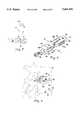
- FIG. 1is a longitudinal, partial sectional view of a preferred embodiment of the apparatus of the present invention.
- FIG. 2is an end view of the apparatus of FIG. 1.
- FIG. 3is a view similar to that of FIG. 1 but with the mandrel removed therefrom.
- FIG. 4is an end view of the apparatus of FIG. 3.
- FIG. 5is a side, elevational view of the mandrel of the present invention after removal from the apparatus of FIG. 1.
- FIG. 6is an end view of the mandrel of FIG. 5.
- FIG. 7is a partially schematic, lateral view of a portion of the lumbar spine showing the use of the apparatus of FIG. 1 to align the fourth and fifth lumbar vertebrae.
- FIG. 8is an exploded, perspective view of a monolithic implant for use in accordance with the method of the present invention.
- FIG. 9is a lateral view of the fourth and fifth lumbar vertebrae of a human spinal column having the monolithic implant of FIG. 8 inserted therebetween and having a portion of the bodies of the vertebrae shown cut away and/or in shadow lines to show the engagement of the vertebral bodies by the implant.
- FIG. 10is a top, plan view of an alternative embodiment of the apparatus of the present invention showing the two halves of the body in their first, side-by-side position.
- FIG. 11is a top, plan view of the apparatus of FIG. 10 showing the two halves of the body in the second position.
- FIG. 1a presently preferred embodiment of an apparatus for aligning adjacent vertebrae constructed in accordance with the teachings of the present invention is shown in FIG. 1.
- the apparatusindicated generally at reference numeral 10 is comprised of an elongate handle 11 and an elongate body 12.
- the body 12is comprised of first and second side-by-side members 13 and 14, respectively, the first member 13 being integrally mounted to handle 11 and the second member 14 being movable relative to the first member 13 in the direction of the longitudinal axis of the shaft 15 of handle 11.
- the shaft 15 of handle 11is provided with a longitudinal bore 16 therethrough having a mandrel 17 positioned therein, the second member 14 being mounted to mandrel 17.
- the shaft 15is provided with a tubular barrel 18 having a collar 19 positioned therein.
- Collar 19is also provided with a longitudinal bore 16', the longitudinal axis of which is aligned with the longitudinal axis of the bore 16 in mandrel 17 which is provided with a set of threads 20 for receiving the threaded end 21 of mandrel 17.
- Collar 19is retained within barrel 18 by the keeper 22 which is retained on the end of barrel 18 by screws 23.
- An adjustment knob 24is integrally mounted to collar 18 by screws 26.
- first member 13is provided with a half round hollow 27 for receiving the round mandrel 17 for retaining the two members 13 and 14 in tight, parallel, side-by-side relationship when second member 14 is moved from the first position to the second position.
- the two members 13 and 14When the first and second members 13 and 14 are in the first side-by-side position shown in FIGS. 1 and 2, e.g., when the mandrel 17 is rotated to draw the end 36 of second member 14 against the end 54 of handle 11, the two members 13 and 14 form an elongate body 12 having a shape which is similar to the shape of the monolithic implant 122 shown in FIGS. 8 and 9. Referring, however, to the body 12 for the time being, when side-by-side, the two members 13 and 14 form a body 12 that is comprised of first and second sides 32 and third and fourth sides 34 providing a substantially rectangularly-shaped cross-section.
- the height H of the rectangularly-shaped cross-sectionis defined by first and second sides 32 and the width W is defined by the third and fourth sides 34 and, as is apparent by comparison of H and W, the height H of body 12 is less than the width W.
- His minimized to facilitate insertion of the second end 36 into, and positioning of body 12 in, the disk space from which a portion of the intervertebral disk 30 was removed and W is maximized to provide the desired stabilization to adjacent vertebrae 33 and 37.
- Third and fourth sides 34are arched from one end of body 12 to the other to provide the portion of body 12 intermediate the ends 25 and 36 with a width W' which is larger than the width W" at the ends 25 and 36.
- body 12is described as being a biplanar, bi-convex body.
- the convex, or arched, sides 34 of body 12are provided with a plurality of teeth 38 for biting into the adjacent vertebrae 33 and 37 as will be explained in more detail below.
- the end 36 of body 12is formed in a blunt, or rounded shape to reduce the likelihood of injury to the nerves of the spinal cord during insertion into the disk space.
- FIG. 7the use of the apparatus 10 for reduction of spondylolisthesis is shown.
- the fourth lumbar vertebrae (L4) 33is shown as having shifted anteriorally, leaving that vertebrae out of alignment with the fifth lumbar vertebrae (L5) 37 and the first vertebrae comprising the sacrum 35.
- surgeryis performed as in a simple diskectomy and the intervertebral disk (not shown) is exposed through a small laminotomy. Disk material is removed and any nerve root compression is corrected.
- the posterior longitudinal ligament (not shown) and disk cartilageare removed until the surface of the bodies 29 and 31 of the adjacent vertebrae (L4 and L5) 33 and 37, respectively, are exposed above and below the disk space.
- the adjacent vertebrae 33 and 37are distracted to open the disk space.
- the body 12 of apparatus 10having the first and second members 13 and 14 initially in the above-described side-by-side relationship, is then inserted into the disk space with the top and bottom thereof, i.e., the first and second substantially planar sides 32, engaging the adjacent vertebrae 33 and 37 so that the teeth 38 formed on the third and fourth sides 34 of body 12 extend into the disk space without engaging the adjacent vertebrae 33 and 37.
- the implantis oriented in the disk space so that, when rotated as described below, the first member 13 is the portion of the body 12 which contacts the body 31 of L5 37 and the second member contacts the body 29 of L4 33.
- body 12is oriented so that first member 13 is positioned in close proximity to the body 31 of the vertebrae 37 which is aligned with the axis, or centerline, of the spinal column and second member 14 is positioned in close proximity to the body 29 of the vertebrae 33 which is out of alignment.
- the body 12 of apparatus 10is inserted until the middle portion of first member 13 is positioned adjacent the concavity in the upper surface of the body 31 of the L5 37.
- mandrel 17is then rotated to advance the second member 14, e.g., the portion having the wider width W", anteriorally until the middle portion, e.g., the portion having the wider width W", of second member 14 is positioned adjacent the concavity of the lower surface of the body 29 of L4 33.
- the wider middle portion W" of each of the members 13 and 14 comprising the body 12 of apparatus 10provides maximal engagement of the concave shaped surface of the body of the vertebrae when the body 12 is rotated by approximately 90° as described below.
- first and second members 13 and 14are approximately aligned with each of the adjacent vertebrae 33 and 37 by positioning the wide, middle portion of each member in the respective concavities of the vertebrae, using the barrel 18 of handle 11, the body 12 of apparatus 10 is rotated by approximately 90° to cause the teeth 38 formed on the surfaces 34 of first and second members 13 and 14 to engage the bodies 29 and 31 of the respective adjacent vertebrae 33 and 37 as shown in FIG. 7.
- mandrel 17is then rotated in the opposite direction to draw second member 14 back into the first, side-by-side, parallel relationship with first member 13, pulling the vertebrae to which it is engaged, i.e., L4 33, back into alignment with L5 37.
- the diskectomy and laminotomyare performed bilaterally.
- the above-described surgical procedureis performed to the side of the center line of the adjacent vertebrae such that the portion of the intervertebral disk which is removed is "off center" relative to the bodies 29 and 31 of the respective adjacent vertebrae 33 and 37. It is preferred that an identical surgery be performed on the other, or second, side of the center line of the adjacent vertebrae and that the body 12 of a second apparatus 10 (not shown in the figures for purposes of clarity) be inserted into the disk space after that procedure.
- the adjacent vertebrae 33 and 37are then aligned by rotation of the respective adjustment knobs 24 of both apparatus 10 until the vertebrae are aligned. In this fashion, the body 12 of one of the two apparatus 10 retains the adjacent vertebrae in alignment even after removal of the other implant.
- Removal of the body 12is accomplished by rotation by approximately 90° (preferably in the direction opposite the direction of rotation which was utilized to cause the teeth 38 to engage the respective adjacent vertebrae 33 and 37) so as to disengage the teeth 38 from L4 33 and L5 37.
- the implant 122(see FIG. 8) is inserted into the disk space from which the first body 12 was removed.
- Implant 122is constructed in essentially the same shape as the body 12 of apparatus 10 when both of the first and second members 13 and 14 are in the first, side-by-side, parallel position described above but is monolithic in its construction, i.e., is not split longitudinally in the manner in which the body 12 of apparatus 10 is split into first and second members 13 and 14.
- implant 122Because of the similarity in the shape and component parts of the body 12 and implant 122, it is not necessary to describe the component parts of monolithic implant 122 in further detail other than to note that the corresponding parts of implant 122 are numbered with the same reference numerals but preceded with a "1", e.g., the teeth 38 of body 12 are numbered as 138 on implant 122.
- Implant 122 and methods for spinal fusion utilizing implant 122are described in detail in my co-pending application, filed on the same date as the present application, entitled ROTATING, LOCKING, MIDDLE-EXPANDED INTERVERTEBRAL DISK STABILIZER AND METHOD, Ser. No. 08/475,211 which is hereby incorporated into this specification in its entirety by this specific reference thereto.
- implant 122also comprises a lock 124 which is substantially square when viewed from the end 140 along the axis of the bore 128 therethrough and U-shaped when viewed from the side.
- the inside surfaces 142 of the arms 144 of the U-shaped lock 124are flat for contacting the first and second sides 132 of monolithic implant 122 to prevent rotation of lock 124 relative to implant 122 when lock 124 is mounted to implant 122 and secured thereto by bolt 126.
- the surfaces 142are provided with a slot 146 for receiving a complementary-shaped key 148 (it will be recognized that the key 148 could be formed on the surfaces 142 and that slot 146 could be formed in the first and second sides 132 of implant 122) to facilitate assembly of lock 124 to implant 122 so that the bore 128 in lock 124 is aligned with the bore 130 in implant 122.
- the sides of the square end 140 of lock 124provide surfaces 150 for bearing against the bodies 29 and 31 of the respective adjacent vertebrae 33 and 37 as explained below, but it will be recognized by those skilled in the art who have the benefit of this disclosure that the bearing surfaces 150 need not be flat and that the end 140 of lock 124 need not necessarily be square.
- the monolithic implant 122is inserted into the disk space from which the body 12 of the first apparatus 10 is removed on the end of an elongate applicator (not shown here but shown in detail in the above-referenced and incorporated co-pending application) which is provided with threads for mating with the threads in the bore 130 in implant 122.
- the disk spaceis then packed with cancellous bone chips (not shown).
- the monolithic implant 122is then inserted into the disk space with the flat surfaces 132 adjacent the bodies 29 and 31 of adjacent vertebrae 33 and 37 and moved in an anterior-posterior direction so as to enable the implant 122 to be positioned in the disk space at a position in which the expanded, middle portion and the smaller width ends 125 and 136 of the third and fourth sides 134 of implant 122 contact the respective lower and upper surfaces of the bodies 29 and 31 of the adjacent vertebrae 33 and 37 when rotated by approximately 90° using the applicator.
- the respective lower and upper surfaces of the bodies 29 and 31 of vertebrae 33 and 37are slightly concave such that the larger width middle portion W" of implant 122 allows the implant 122 to engage substantially more of the respective surfaces of the vertebral bodies 29 and 31 than conventional prosthetic devices, thereby providing increased stability to the fusion once further rotation of implant 122 in the disk space is prevented as described below.
- the applicatoris then detached from the monolithic implant 122 by unscrewing and backed out of the incision in the patient.
- Lock 124is then inserted through that same incision and, using the slot 146 and key 148, the bore 128 in lock 124 and bore 130 in implant 122 are aligned and the bolt 126 is inserted and tightened to secure lock 124 to the implant 122. Securing the lock 124 to implant 122 in this manner prevents relative rotation between lock 24 and implant 122.
- bearing surfaces 150 of lock 124bear against the bodies 29 and 31 of the respective adjacent vertebrae 33 and 37 to prevent rotation of the lock 124 relative to the adjacent vertebrae 33 and 37 against which the bearing surfaces 150 bear, rotation of the implant 122 in the disk space is prevented.
- the bearing surfaces 150bear against the cortical end plate of the bodies 29 and 31 of the respective adjacent vertebrae 33 and 37, which is comprised of non-cancellous bone, and provides a hard, relatively smooth surface against which the bearing surfaces 150 bear.
- the end 140 of lock 124is preferably supplied in a plurality of different sizes and shapes other than the square shaped end 140 shown in the figures so as to allow the surgeon to select an appropriately sized and shaped lock which provides a close fit with the space between vertebral bodies.
- a small amount of a physiologically compatible adhesive of a type known in the artis applied over the cancellous bone chips just medial to the implants to close off the remaining portion of the openings into the disk space.
- the patientshould be able to ambulate soon after the procedure because of the stability imparted to the spinal column by the implant of the present invention. Before narrowing of the disk space occurs, the cancellous bone chips will have started the fusion process.
- FIGS. 10 and 11there is shown an alternative embodiment of the apparatus, indicated generally at reference numeral 10a, of the present invention.
- the component parts of apparatus 10aare labelled with the reference numeral (and the "a" designation) of the corresponding parts of the apparatus 10.
- Apparatus 10ais comprised of a handle 11a and body 12a, the body 12a being comprised of first (fixed) and second (movable) members 13a and 14a, respectively.
- the second member 14ais mounted to a mandrel 17a positioned in a longitudinal bore 16a in the shaft 15a by a swivel joint 40a and moves relative to first member 13a by action of the threads 21a formed on the outside surface of mandrel 17a on the threads 20a formed on the shaft 15a of handle 11a.
- the body 12a of apparatus 10ais shaped in the same substantially rectangular cross-sectional shape as the body 12 of apparatus 10 and the component parts of apparatus 10a function in the same manner as the parts of apparatus 10.
- Apparatus 10aalso includes a plurality of fine serrations 42a formed on the opposed surfaces 44a and 46a of first and second members 13a and 14a, respectively.
- the serrations 42aact to resist longitudinal movement of second member 14a relative to first member 13a.
Landscapes
- Health & Medical Sciences (AREA)
- Engineering & Computer Science (AREA)
- Biomedical Technology (AREA)
- Orthopedic Medicine & Surgery (AREA)
- Life Sciences & Earth Sciences (AREA)
- General Health & Medical Sciences (AREA)
- Neurology (AREA)
- Veterinary Medicine (AREA)
- Transplantation (AREA)
- Heart & Thoracic Surgery (AREA)
- Public Health (AREA)
- Animal Behavior & Ethology (AREA)
- Cardiology (AREA)
- Vascular Medicine (AREA)
- Oral & Maxillofacial Surgery (AREA)
- Surgery (AREA)
- Nuclear Medicine, Radiotherapy & Molecular Imaging (AREA)
- Medical Informatics (AREA)
- Molecular Biology (AREA)
- Physical Education & Sports Medicine (AREA)
- Prostheses (AREA)
Abstract
Description
The present application is a continuation-in-part of International Application No. PCT/US95/03347, entitled MIDDLE EXPANDED, REMOVABLE, INTERVERTEBRAL DISK IMPLANT AND METHOD OF LUMBAR INTERVERTEBRAL DISK STABILIZATION, filed on Mar. 17, 1995 which is a continuation-in-part of U.S. application Ser. No. 08/210,229, filed Mar. 18, 1994 and having that same title.
The present invention relates to a method and apparatus for reduction of spondylolisthesis, e.g., misalignment of the vertebrae comprising the spinal column. More specifically, the present invention relates to an apparatus which is inserted into the disk space between two adjacent, misaligned vertebrae, engages the bodies of the adjacent vertebrae, and pulls the adjacent vertebrae back into alignment and a method utilizing that apparatus.
Treatment of disorders of the spinal column, especially in the cervical and lumbar regions, continues to be a challenging field of medicine. Classical treatments for conditions involving subluxation of one vertebrae upon another, resulting in misalignment of the spinal column, involve the use of screws which extend through a plate and which are tightened to draw the misaligned vertebrae back into alignment. However, such conditions often involve damage to the intervertebral disk, e.g., rupture or herniation, which may result in compression of a nerve root. If the herniation is large, compression may be bilateral. This condition is usually not corrected by re-aligning the vertebrae with a plate and screws such that surgical removal of the disk followed by fusion is often indicated after reduction of spondylolisthesis.
However, diskectomy with fusion is not ideal because the replaced bone does not have the function of the cartilaginous tissue of the disk, i.e. no cushioning effect, and has complications because of several factors. First, conventional bone plugs used to pack the disk space do not conform to the space of the disk because the disk bulges maximally in the center. The disk space is wider in the middle and narrower at its anterior and posterior ends. For this reason, the various bone plugs which are currently available commercially have only four contact points, i.e. at the front and back of the disk space. Secondly, access to the disk is from the side of the dorsal spine of the adjacent vertebrae, leaving a space that is "off-center" relative to the bodies of the adjacent vertebrae such that the stability of the implant is even more problematical than might be apparent from the limited contact resulting from the shape of the intervertebral space. Another complication is the possibility of infection or other conditions which may require the removal of the implant. Also, if the bone pieces do not fuse, they may eventually extrude out of the disk space, causing pressure on the nerve roots.
Various prosthetic disk plugs, or implants, are disclosed in the art, but all are characterized by limitations of not conforming to the shape of the disk space, lack of stability when inserted off-center, inability to be removed, or other disadvantages. For instance, U.S. Pat. No. 4,863,476 (and its European counterpart, EP-A-0260044) describes an elongated body divided longitudinally into two portions having a cam device movable therebetween for increasing the space between the two body portions once inserted into the disk space. However, that device is generally cylindrical in shape such that the only contact points between the device and the vertebral bodies are at the front and back of the disk space, creating increased likelihood of instability and generally rendering that device unsuitable for use after partial diskectomy. The art also discloses intervertebral disk prostheses (e.g., U.S. Pat. Nos. 3,867,728, 4,309,777, 4,863,477 and 4,932,969 and French Patent Application No. 8816184) which may have more general contact with the adjacent disks, but which are not intended for use in fusion of the disks. The art also includes spinal joint prostheses such as is described in U.S. Pat. No. 4,759,769, which is again not indicated for use when fusion is the preferred surgical intervention.
There is, therefore, a need for an improved method of treatment of conditions involving misalignment of the vertebrae of the spinal column, or spondylolisthesis, and it is a principal object of the present invention to provide such a method and an apparatus for use in connection with that method.
This need is met in the present invention by providing an apparatus for aligning vertebrae comprising an elongate handle having a longitudinal bore therethrough, an implant comprised of first and second side-by-side members, the first member being integrally mounted to the handle and the second member being movable relative to the first member in the direction of the longitudinal axis of the handle, and means formed on opposite sides of the implant for selectively engaging adjacent vertebrae to prevent relative movement between the respective first and second members and the adjacent vertebrae. A mandrel is positioned in the bore in the handle and is connected to the second member for moving the second member relative to the first member in the direction of the longitudinal axis of the handle. To facilitate precise movement of the second member relative to the first, and to confer the mechanical advantage on that movement which may be required to draw the adjacent vertebrae into alignment, the mandrel is preferably threaded and the bore in the handle is provided with a matching set of threads such that rotation of the mandrel causes movement of the second member along the longitudinal axis of the handle.
In a second aspect, the present invention involves a method of aligning adjacent vertebrae after removing a portion of the intervertebral disk from therebetween to form a disk space comprising the steps of inserting an elongate implant having means formed on opposite sides thereof for selectively engaging the vertebrae adjacent the disk space into the disk space, the implant being comprised of first and second side-by-side members, with the vertebrae engaging means extending into the disk space without engaging the adjacent vertebrae and moving the second member relative to the first member until the first and second members are approximately aligned with the adjacent vertebrae. The implant is rotated by approximately 90° to cause the vertebrae engaging means formed thereon to engage the vertebrae and the second member is then moved relative to the first member to align the vertebrae to which it is engaged with the vertebrae to which the first member is engaged. In the preferred embodiment of the method of the present invention, the disk is removed on both sides of the center line of the spine and a second implant, identical to the first, is inserted between the adjacent vertebrae on the side of the disk space opposite the first implant and the misaligned vertebrae are then drawn back into alignment by simultaneous movement of the second members of both implants. One of the two implants is then removed and replaced with a monolithic implant having roughly the same size and shape while the vertebrae are held in alignment by the other implant. After replacement of one implant with a first monolithic implant, the other implant is replaced with a second monolithic implant.
FIG. 1 is a longitudinal, partial sectional view of a preferred embodiment of the apparatus of the present invention.
FIG. 2 is an end view of the apparatus of FIG. 1.
FIG. 3 is a view similar to that of FIG. 1 but with the mandrel removed therefrom.
FIG. 4 is an end view of the apparatus of FIG. 3.
FIG. 5 is a side, elevational view of the mandrel of the present invention after removal from the apparatus of FIG. 1.
FIG. 6 is an end view of the mandrel of FIG. 5.
FIG. 7 is a partially schematic, lateral view of a portion of the lumbar spine showing the use of the apparatus of FIG. 1 to align the fourth and fifth lumbar vertebrae.
FIG. 8 is an exploded, perspective view of a monolithic implant for use in accordance with the method of the present invention.
FIG. 9 is a lateral view of the fourth and fifth lumbar vertebrae of a human spinal column having the monolithic implant of FIG. 8 inserted therebetween and having a portion of the bodies of the vertebrae shown cut away and/or in shadow lines to show the engagement of the vertebral bodies by the implant.
FIG. 10 is a top, plan view of an alternative embodiment of the apparatus of the present invention showing the two halves of the body in their first, side-by-side position.
FIG. 11 is a top, plan view of the apparatus of FIG. 10 showing the two halves of the body in the second position.
Referring now to the figures, a presently preferred embodiment of an apparatus for aligning adjacent vertebrae constructed in accordance with the teachings of the present invention is shown in FIG. 1. The apparatus, indicated generally atreference numeral 10 is comprised of anelongate handle 11 and anelongate body 12. Thebody 12 is comprised of first and second side-by-side members first member 13 being integrally mounted to handle 11 and thesecond member 14 being movable relative to thefirst member 13 in the direction of the longitudinal axis of theshaft 15 ofhandle 11.
Theshaft 15 ofhandle 11 is provided with alongitudinal bore 16 therethrough having amandrel 17 positioned therein, thesecond member 14 being mounted tomandrel 17. At the end oppositefirst member 13, theshaft 15 is provided with atubular barrel 18 having acollar 19 positioned therein. Collar 19 is also provided with a longitudinal bore 16', the longitudinal axis of which is aligned with the longitudinal axis of thebore 16 inmandrel 17 which is provided with a set ofthreads 20 for receiving the threadedend 21 ofmandrel 17. Collar 19 is retained withinbarrel 18 by thekeeper 22 which is retained on the end ofbarrel 18 byscrews 23. Anadjustment knob 24 is integrally mounted tocollar 18 byscrews 26. As a result of this construction, whenmandrel 17 is rotated by turningadjustment knob 24, thesecond member 14 moves relative tofirst member 13 from a first position in which themembers shaft 15 ofhandle 11 in which the two members remain parallel to each other but are no longer side-by-side as shown in FIG. 7. Referring to FIGS. 3-6, it can be seen thatfirst member 13 is provided with a half round hollow 27 for receiving theround mandrel 17 for retaining the twomembers second member 14 is moved from the first position to the second position.
When the first andsecond members mandrel 17 is rotated to draw the end 36 ofsecond member 14 against the end 54 ofhandle 11, the twomembers elongate body 12 having a shape which is similar to the shape of themonolithic implant 122 shown in FIGS. 8 and 9. Referring, however, to thebody 12 for the time being, when side-by-side, the twomembers body 12 that is comprised of first andsecond sides 32 and third andfourth sides 34 providing a substantially rectangularly-shaped cross-section. The height H of the rectangularly-shaped cross-section is defined by first andsecond sides 32 and the width W is defined by the third andfourth sides 34 and, as is apparent by comparison of H and W, the height H ofbody 12 is less than the width W. As will be explained below, H is minimized to facilitate insertion of the second end 36 into, and positioning ofbody 12 in, the disk space from which a portion of theintervertebral disk 30 was removed and W is maximized to provide the desired stabilization toadjacent vertebrae fourth sides 34 are arched from one end ofbody 12 to the other to provide the portion ofbody 12 intermediate theends 25 and 36 with a width W' which is larger than the width W" at theends 25 and 36. Because thesides 32 ofbody 12 are substantially flat and thesides 34 are arched from oneend 25 to the other end 36,body 12 is described as being a biplanar, bi-convex body. The convex, or arched, sides 34 ofbody 12 are provided with a plurality ofteeth 38 for biting into theadjacent vertebrae body 12 is formed in a blunt, or rounded shape to reduce the likelihood of injury to the nerves of the spinal cord during insertion into the disk space.
Referring now to FIG. 7, the use of theapparatus 10 for reduction of spondylolisthesis is shown. In FIG. 7, the fourth lumbar vertebrae (L4) 33 is shown as having shifted anteriorally, leaving that vertebrae out of alignment with the fifth lumbar vertebrae (L5) 37 and the first vertebrae comprising thesacrum 35. To correct this misalignment, surgery is performed as in a simple diskectomy and the intervertebral disk (not shown) is exposed through a small laminotomy. Disk material is removed and any nerve root compression is corrected. The posterior longitudinal ligament (not shown) and disk cartilage are removed until the surface of thebodies
Using spreaders such as those disclosed in International Application No. PCT/US95/03347, which reference is hereby incorporated into this specification in its entirety by this specific reference thereto, theadjacent vertebrae body 12 ofapparatus 10, having the first andsecond members planar sides 32, engaging theadjacent vertebrae teeth 38 formed on the third andfourth sides 34 ofbody 12 extend into the disk space without engaging theadjacent vertebrae first member 13 is the portion of thebody 12 which contacts thebody 31 ofL5 37 and the second member contacts thebody 29 ofL4 33. In other words,body 12 is oriented so thatfirst member 13 is positioned in close proximity to thebody 31 of thevertebrae 37 which is aligned with the axis, or centerline, of the spinal column andsecond member 14 is positioned in close proximity to thebody 29 of thevertebrae 33 which is out of alignment. Thebody 12 ofapparatus 10 is inserted until the middle portion offirst member 13 is positioned adjacent the concavity in the upper surface of thebody 31 of theL5 37. Using theadjustment knob 24,mandrel 17 is then rotated to advance thesecond member 14, e.g., the portion having the wider width W", anteriorally until the middle portion, e.g., the portion having the wider width W", ofsecond member 14 is positioned adjacent the concavity of the lower surface of thebody 29 ofL4 33. As noted above, the wider middle portion W" of each of themembers body 12 ofapparatus 10 provides maximal engagement of the concave shaped surface of the body of the vertebrae when thebody 12 is rotated by approximately 90° as described below. Those skilled in the art who have the benefit of this disclosure will recognize that, depending upon the circumstances of each surgery, it may also be advantageous to "pre-adjust" thebody 12 by advancing thesecond member 14 to the second position by the amount of the misalignment before inserting thebody 12 ofapparatus 10 into the disk space and that the amount of slippage ofL4 33 relative toL5 37 is calculated using known methods and/or estimated from X-ray films or other images.
Once the first andsecond members adjacent vertebrae barrel 18 ofhandle 11, thebody 12 ofapparatus 10 is rotated by approximately 90° to cause theteeth 38 formed on thesurfaces 34 of first andsecond members bodies adjacent vertebrae adjustment knob 24,mandrel 17 is then rotated in the opposite direction to drawsecond member 14 back into the first, side-by-side, parallel relationship withfirst member 13, pulling the vertebrae to which it is engaged, i.e.,L4 33, back into alignment withL5 37.
For reasons which will be made clear by the following description, in a particularly preferred embodiment of the method of the present invention, the diskectomy and laminotomy are performed bilaterally. In other words, the above-described surgical procedure is performed to the side of the center line of the adjacent vertebrae such that the portion of the intervertebral disk which is removed is "off center" relative to thebodies adjacent vertebrae body 12 of a second apparatus 10 (not shown in the figures for purposes of clarity) be inserted into the disk space after that procedure. Theadjacent vertebrae apparatus 10 until the vertebrae are aligned. In this fashion, thebody 12 of one of the twoapparatus 10 retains the adjacent vertebrae in alignment even after removal of the other implant.
Removal of thebody 12 is accomplished by rotation by approximately 90° (preferably in the direction opposite the direction of rotation which was utilized to cause theteeth 38 to engage the respectiveadjacent vertebrae 33 and 37) so as to disengage theteeth 38 fromL4 33 andL5 37. While the body of the second apparatus remains in the disk space on the second side of the center line, the implant 122 (see FIG. 8) is inserted into the disk space from which thefirst body 12 was removed.Implant 122 is constructed in essentially the same shape as thebody 12 ofapparatus 10 when both of the first andsecond members body 12 ofapparatus 10 is split into first andsecond members body 12 andimplant 122, it is not necessary to describe the component parts ofmonolithic implant 122 in further detail other than to note that the corresponding parts ofimplant 122 are numbered with the same reference numerals but preceded with a "1", e.g., theteeth 38 ofbody 12 are numbered as 138 onimplant 122.Implant 122 and methods for spinalfusion utilizing implant 122 are described in detail in my co-pending application, filed on the same date as the present application, entitled ROTATING, LOCKING, MIDDLE-EXPANDED INTERVERTEBRAL DISK STABILIZER AND METHOD, Ser. No. 08/475,211 which is hereby incorporated into this specification in its entirety by this specific reference thereto.
As shown in FIGS. 8 and 9,implant 122 also comprises alock 124 which is substantially square when viewed from theend 140 along the axis of thebore 128 therethrough and U-shaped when viewed from the side. The inside surfaces 142 of thearms 144 of theU-shaped lock 124 are flat for contacting the first andsecond sides 132 ofmonolithic implant 122 to prevent rotation oflock 124 relative to implant 122 whenlock 124 is mounted to implant 122 and secured thereto bybolt 126. Thesurfaces 142 are provided with aslot 146 for receiving a complementary-shaped key 148 (it will be recognized that the key 148 could be formed on thesurfaces 142 and thatslot 146 could be formed in the first andsecond sides 132 of implant 122) to facilitate assembly oflock 124 to implant 122 so that thebore 128 inlock 124 is aligned with thebore 130 inimplant 122. The sides of thesquare end 140 oflock 124 providesurfaces 150 for bearing against thebodies adjacent vertebrae end 140 oflock 124 need not necessarily be square.
Themonolithic implant 122 is inserted into the disk space from which thebody 12 of thefirst apparatus 10 is removed on the end of an elongate applicator (not shown here but shown in detail in the above-referenced and incorporated co-pending application) which is provided with threads for mating with the threads in thebore 130 inimplant 122. The disk space is then packed with cancellous bone chips (not shown). When the threaded end of the applicator is screwed all the way into thebore 130 so as to prevent relative movement of theimplant 122 and its applicator, themonolithic implant 122 is then inserted into the disk space with theflat surfaces 132 adjacent thebodies adjacent vertebrae implant 122 to be positioned in the disk space at a position in which the expanded, middle portion and the smaller width ends 125 and 136 of the third andfourth sides 134 ofimplant 122 contact the respective lower and upper surfaces of thebodies adjacent vertebrae bodies vertebrae implant 122 allows theimplant 122 to engage substantially more of the respective surfaces of thevertebral bodies implant 122 in the disk space is prevented as described below.
Once positioned in the disk space so as to provide maximum stabilization, the applicator is then detached from themonolithic implant 122 by unscrewing and backed out of the incision in the patient.Lock 124 is then inserted through that same incision and, using theslot 146 and key 148, thebore 128 inlock 124 and bore 130 inimplant 122 are aligned and thebolt 126 is inserted and tightened to securelock 124 to theimplant 122. Securing thelock 124 to implant 122 in this manner prevents relative rotation betweenlock 24 andimplant 122. Because the bearing surfaces 150 oflock 124 bear against thebodies adjacent vertebrae lock 124 relative to theadjacent vertebrae implant 122 in the disk space is prevented. Those skilled in the art who have the benefit of this disclosure will recognize that the bearing surfaces 150 bear against the cortical end plate of thebodies adjacent vertebrae end 140 oflock 124 is preferably supplied in a plurality of different sizes and shapes other than the squareshaped end 140 shown in the figures so as to allow the surgeon to select an appropriately sized and shaped lock which provides a close fit with the space between vertebral bodies. Once themonolithic implant 122 is locked in place on the first side of the center line of theadjacent vertebrae body 12 of thesecond apparatus 10 on the second side of the center line, which has remained in place throughout the procedure, is then removed. The disk space is then packed with cancellous bone chips through this second side and a second monolithic implant 122 (also not shown) is inserted, positioned, rotated, and locked in its place in the same manner as described above.
If necessary, a small amount of a physiologically compatible adhesive of a type known in the art is applied over the cancellous bone chips just medial to the implants to close off the remaining portion of the openings into the disk space. The patient should be able to ambulate soon after the procedure because of the stability imparted to the spinal column by the implant of the present invention. Before narrowing of the disk space occurs, the cancellous bone chips will have started the fusion process.
Referring now to FIGS. 10 and 11, there is shown an alternative embodiment of the apparatus, indicated generally atreference numeral 10a, of the present invention. Where possible, the component parts ofapparatus 10a are labelled with the reference numeral (and the "a" designation) of the corresponding parts of theapparatus 10.Apparatus 10a is comprised of ahandle 11a andbody 12a, thebody 12a being comprised of first (fixed) and second (movable)members second member 14a is mounted to amandrel 17a positioned in alongitudinal bore 16a in theshaft 15a by a swivel joint 40a and moves relative tofirst member 13a by action of thethreads 21a formed on the outside surface ofmandrel 17a on thethreads 20a formed on theshaft 15a ofhandle 11a. Thebody 12a ofapparatus 10a is shaped in the same substantially rectangular cross-sectional shape as thebody 12 ofapparatus 10 and the component parts ofapparatus 10a function in the same manner as the parts ofapparatus 10.
Although described in terms of the preferred embodiment shown in the figures, this embodiment is shown to exemplify the present invention, it being recognized by those skilled in the art that certain changes can be made to the specific structure of the preferred embodiment shown and described without departing from the spirit of the present invention. All such modifications are intended to fall within the scope of the following claims.
Claims (18)
1. Apparatus for aligning adjacent vertebrae comprising:
an elongate handle having a longitudinal bore therethrough;
a mandrel positioned in-the bore in said handle and movable therein:
a body comprised of first and second side-by-side members, the first member being mounted to the end of said handle and the second member being mounted to the end of said mandrel; and
means formed on said body for selectively engaging adjacent vertebrae when said body is inserted therebetween to prevent relative movement between the respective first and second members and the respective adjacent vertebrae to which the first and second members are engaged.
2. The apparatus of claim 1 wherein said body is formed in substantially rectangularly-shaped cross-section, said vertebrae engaging means being formed on opposite sides thereof.
3. The apparatus of claim 2 wherein the height of said rectangularly-shaped body is less than the width of said body.
4. The apparatus of claim 2 wherein the sides of said rectangularly-shaped body defining the height of said body are arched from the first end of said body to the second end of said body to provide said body with a width in the portion intermediate the ends thereof which is larger than the width at the ends of said body.
5. The apparatus of claim 1 wherein said vertebrae engaging means comprises teeth formed on the surface of said body.
6. The apparatus of claim 1 wherein said mandrel and the bore of said handle are provided with matching threads whereby rotation of said mandrel causes movement of said mandrel relative to said handle in the direction of the longitudinal axis of said handle.
7. Apparatus for aligning adjacent vertebrae when inserted therebetween comprising:
an elongate mandrel;
a first member formed on the end of said mandrel;
an elongate handle having a bore therethrough, said mandrel being positioned in the bore and movable therein;
a second member formed on the end of said handle, said first and second members forming an elongate body having a substantially rectangular cross-section when said mandrel is positioned in the bore in said handle and said first and second members are side-by-side; and
a plurality of teeth formed on said first and second members for selectively engaging the adjacent vertebrae.
8. The apparatus of claim 7 wherein the body formed by said first and second members is formed in bi-planar, biconvex shape.
9. The apparatus of claim 7 wherein the ends of the elongate body formed by said first and second members are of smaller width than the middle of the body.
10. The apparatus of claim 9 wherein the teeth formed on said first and second members are located on the portion of said first and second members forming the middle portion of the body.
11. The apparatus of claim 7 wherein the side of said second member abutting said first member when said first and second members are side-by-side is provided with a half round hollow for retaining said first and second members in tight, parallel, side-by-side relationship.
12. Apparatus for insertion between and alignment of adjacent vertebrae comprising:
a body formed of first and second side-by-side elongate members:
an elongate handle having said first member mounted thereto;
an elongate mandrel having said second member mounted thereto and movable relative to and along the longitudinal axis of said handle for moving said first member relative to said second member along the longitudinal axis thereof: and
a plurality of teeth formed on said body for engaging adjacent vertebrae when said body is inserted therebetween using said handle.
13. The apparatus of claim 12 wherein said body is substantially rectangularly-shaped in cross-section, the sides of said rectangularly-shaped body forming the width of said body having a dimension larger than the sides of said body forming the height of said body.
14. The apparatus of claim 13 wherein said teeth are formed on the sides of said body forming the height of said body.
15. The apparatus of claim 13 wherein the width of said body is smaller at the ends of said body than in the middle of said body.
16. The apparatus of claim 15 wherein the teeth are formed on the sides of said body forming the height of said body and in the portion of said body forming the middle of said body.
17. The apparatus of claim 12 wherein said handle is provided with a longitudinal bore and said mandrel is positioned therein.
18. The apparatus of claim 12 wherein said second member is provided with a rounded surface for receiving a complementary-shaped surface on said first member for maintaining said first and second members in side-by-side alignment during movement of said first member relative to said second member.
Priority Applications (1)
| Application Number | Priority Date | Filing Date | Title |
|---|---|---|---|
| US08/486,322US5601556A (en) | 1994-03-18 | 1995-06-07 | Apparatus for spondylolisthesis reduction |
Applications Claiming Priority (3)
| Application Number | Priority Date | Filing Date | Title |
|---|---|---|---|
| US08/210,229US6093207A (en) | 1994-03-18 | 1994-03-18 | Middle expanded, removable intervertebral disk stabilizer disk |
| PCT/US1995/003374WO1995025487A1 (en) | 1994-03-18 | 1995-03-17 | Middle expanded, removable intervertebral disk stabilizer and method of lumbar intervertebral disk stabilization |
| US08/486,322US5601556A (en) | 1994-03-18 | 1995-06-07 | Apparatus for spondylolisthesis reduction |
Related Parent Applications (1)
| Application Number | Title | Priority Date | Filing Date |
|---|---|---|---|
| US08/210,229Continuation-In-PartUS6093207A (en) | 1994-03-18 | 1994-03-18 | Middle expanded, removable intervertebral disk stabilizer disk |
Publications (1)
| Publication Number | Publication Date |
|---|---|
| US5601556Atrue US5601556A (en) | 1997-02-11 |
Family
ID=22782081
Family Applications (3)
| Application Number | Title | Priority Date | Filing Date |
|---|---|---|---|
| US08/210,229Expired - Fee RelatedUS6093207A (en) | 1994-03-18 | 1994-03-18 | Middle expanded, removable intervertebral disk stabilizer disk |
| US08/486,322Expired - Fee RelatedUS5601556A (en) | 1994-03-18 | 1995-06-07 | Apparatus for spondylolisthesis reduction |
| US08/471,910Expired - LifetimeUS5653761A (en) | 1994-03-18 | 1995-06-07 | Method of lumbar intervertebral disk stabilization |
Family Applications Before (1)
| Application Number | Title | Priority Date | Filing Date |
|---|---|---|---|
| US08/210,229Expired - Fee RelatedUS6093207A (en) | 1994-03-18 | 1994-03-18 | Middle expanded, removable intervertebral disk stabilizer disk |
Family Applications After (1)
| Application Number | Title | Priority Date | Filing Date |
|---|---|---|---|
| US08/471,910Expired - LifetimeUS5653761A (en) | 1994-03-18 | 1995-06-07 | Method of lumbar intervertebral disk stabilization |
Country Status (6)
| Country | Link |
|---|---|
| US (3) | US6093207A (en) |
| EP (1) | EP0750482B1 (en) |
| AU (1) | AU2186795A (en) |
| CA (1) | CA2185460C (en) |
| DE (1) | DE69514337T2 (en) |
| WO (1) | WO1995025487A1 (en) |
Cited By (120)
| Publication number | Priority date | Publication date | Assignee | Title |
|---|---|---|---|---|
| US5928243A (en) | 1997-07-16 | 1999-07-27 | Spinal Concepts, Inc. | Pedicle probe and depth gage |
| US5935133A (en) | 1997-08-26 | 1999-08-10 | Spinal Concepts, Inc. | Surgical cable system and method |
| WO1999052447A1 (en)* | 1998-04-09 | 1999-10-21 | Sdgi Holdings, Inc. | Guide sleeve for offset vertebrae |
| US5989250A (en) | 1996-10-24 | 1999-11-23 | Spinal Concepts, Inc. | Method and apparatus for spinal fixation |
| US6030389A (en) | 1997-08-04 | 2000-02-29 | Spinal Concepts, Inc. | System and method for stabilizing the human spine with a bone plate |
| US6053921A (en) | 1997-08-26 | 2000-04-25 | Spinal Concepts, Inc. | Surgical cable system and method |
| US6056749A (en)* | 1999-03-15 | 2000-05-02 | Spineology, Inc. | Method and device for fixing and correcting spondylolisthesis anteriorly |
| US6080193A (en) | 1997-05-01 | 2000-06-27 | Spinal Concepts, Inc. | Adjustable height fusion device |
| US6083228A (en)* | 1998-06-09 | 2000-07-04 | Michelson; Gary K. | Device and method for preparing a space between adjacent vertebrae to receive an insert |
| US6086589A (en)* | 1999-02-02 | 2000-07-11 | Spineology, Inc. | Method and device for fixing spondylolisthesis posteriorly |
| US6159212A (en)* | 1999-08-02 | 2000-12-12 | Schoedinger, Iii; George R. | Surgical tool and method to reduce vertebral displacement |
| US6206922B1 (en) | 1995-03-27 | 2001-03-27 | Sdgi Holdings, Inc. | Methods and instruments for interbody fusion |
| US6375655B1 (en) | 1995-03-27 | 2002-04-23 | Sdgi Holdings, Inc. | Interbody fusion device and method for restoration of normal spinal anatomy |
| US20020058939A1 (en)* | 1997-08-04 | 2002-05-16 | Spinal Concepts, Inc. | System and method for stabilizing the human spine with a bone plate |
| US6416515B1 (en) | 1996-10-24 | 2002-07-09 | Spinal Concepts, Inc. | Spinal fixation system |
| US6442814B1 (en) | 1999-04-23 | 2002-09-03 | Spinal Concepts, Inc. | Apparatus for manufacturing a bone dowel |
| US6447512B1 (en) | 2000-01-06 | 2002-09-10 | Spinal Concepts, Inc. | Instrument and method for implanting an interbody fusion device |
| US6491695B1 (en) | 1999-11-05 | 2002-12-10 | Carl Roggenbuck | Apparatus and method for aligning vertebrae |
| US6517544B1 (en) | 1998-06-09 | 2003-02-11 | Gary K. Michelson | Device and method for preparing a space between adjacent vertebrae to receive an insert |
| US6557226B1 (en) | 1999-04-23 | 2003-05-06 | Michael E. Landry | Apparatus for manufacturing a bone dowel |
| US6613091B1 (en) | 1995-03-27 | 2003-09-02 | Sdgi Holdings, Inc. | Spinal fusion implants and tools for insertion and revision |
| US6692501B2 (en) | 2000-12-14 | 2004-02-17 | Gary K. Michelson | Spinal interspace shaper |
| US20040083002A1 (en)* | 2001-04-06 | 2004-04-29 | Belef William Martin | Methods for treating spinal discs |
| US6736815B2 (en) | 2001-09-06 | 2004-05-18 | Core Medical, Inc. | Apparatus and methods for treating spinal discs |
| US20040127940A1 (en)* | 2000-12-14 | 2004-07-01 | Ginn Richard S. | Apparatus and methods for sealing vascular punctures |
| US20040138750A1 (en)* | 2002-10-29 | 2004-07-15 | St. Francis Medical Technologies, Inc. | Artificial vertebral disk replacement implant with a spacer and method |
| US20040143270A1 (en)* | 2002-10-29 | 2004-07-22 | St. Francis Medical Technologies, Inc. | Tools for implanting artificial vertebral disk and method |
| US20040215197A1 (en)* | 2003-04-24 | 2004-10-28 | Smith Maurice M. | Minimally invasive instruments and methods for preparing vertebral endplates |
| US20050010296A1 (en)* | 2002-10-29 | 2005-01-13 | St. Francis Medical Technologies, Inc. | Artificial vertebral disk replacement implant with crossbar spacer and method |
| US20050015151A1 (en)* | 2001-09-14 | 2005-01-20 | Frederic Fortin | Nucleus prosthesis, the insertion device therefor and the method of fitting same |
| US20050015091A1 (en)* | 1997-10-06 | 2005-01-20 | Sdgi Holdings Inc. | Drill head for use in placing an intervertebral disc device |
| US20050033298A1 (en)* | 2001-10-31 | 2005-02-10 | Ortho Development Corporation | Cervical plate for stabilizing the human spine |
| US20050033299A1 (en)* | 2002-09-06 | 2005-02-10 | Shluzas Alan E. | Surgical instrument for moving a vertebra |
| US20050085854A1 (en)* | 2003-10-17 | 2005-04-21 | Ensure Medical, Inc. | Locator and closure device and method of use |
| US20050113926A1 (en)* | 2003-11-21 | 2005-05-26 | St. Francis Medical Technologies, Inc. | Method of laterally inserting an artificial vertebral disk replacement implant with curved spacer |
| US20050125065A1 (en)* | 2003-11-05 | 2005-06-09 | St. Francis Medical Technologies Inc. | Laterally insertable artificial vertebral disk replacement implant with crossbar spacer |
| US20050143826A1 (en)* | 2003-12-11 | 2005-06-30 | St. Francis Medical Technologies, Inc. | Disk repair structures with anchors |
| US20050154462A1 (en)* | 2003-12-02 | 2005-07-14 | St. Francis Medical Technologies, Inc. | Laterally insertable artificial vertebral disk replacement implant with translating pivot point |
| US20050177189A1 (en)* | 2000-12-14 | 2005-08-11 | Ginn Richard S. | Plug with detachable guidewire element and methods for use |
| US20050196420A1 (en)* | 2003-12-02 | 2005-09-08 | St. Francis Medical Technologies, Inc. | Bioresorbable interspinous process implant for use with intervertebral disk remediation or replacement implants and procedures |
| US6964664B2 (en) | 2000-01-06 | 2005-11-15 | Spinal Concepts Inc. | System and method for stabilizing the human spine with a bone plate |
| US20050267528A1 (en)* | 2000-12-14 | 2005-12-01 | Ensure Medical, Inc. | Vascular plug having composite construction |
| US20050273111A1 (en)* | 1999-10-08 | 2005-12-08 | Ferree Bret A | Methods and apparatus for intervertebral disc removal and endplate preparation |
| US20050283237A1 (en)* | 2003-11-24 | 2005-12-22 | St. Francis Medical Technologies, Inc. | Artificial spinal disk replacement device with staggered vertebral body attachments |
| US20060020342A1 (en)* | 2004-07-21 | 2006-01-26 | Ferree Bret A | Facet-preserving artificial disc replacements |
| US20060025778A1 (en)* | 2004-07-21 | 2006-02-02 | Ferree Bret A | Methods and apparatus for artificial disc replacement (ADR) insertion and other surgical procedures |
| US20060058882A1 (en)* | 2004-01-14 | 2006-03-16 | Haines Timothy G | Methods and apparatus for conformable prosthetic implants |
| US20060069439A1 (en)* | 2004-09-29 | 2006-03-30 | St. Francis Medical Technologies, Inc. | Artificial vertebral disk replacement implant with translating articulation contact surface and method |
| US20060069440A1 (en)* | 2004-09-29 | 2006-03-30 | Zucherman James F | Multi-piece artificial spinal disk replacement device with selectably positioning articulating element |
| US20060069438A1 (en)* | 2004-09-29 | 2006-03-30 | Zucherman James F | Multi-piece artificial spinal disk replacement device with multi-segmented support plates |
| US7083649B2 (en) | 2002-10-29 | 2006-08-01 | St. Francis Medical Technologies, Inc. | Artificial vertebral disk replacement implant with translating pivot point |
| US20060189999A1 (en)* | 2005-02-24 | 2006-08-24 | Paul Zwirkoski | Linked slideable and interlockable rotatable components |
| US20060247778A1 (en)* | 2005-01-26 | 2006-11-02 | Ferree Bret A | Intradiscal devices including spacers facilitating posterior-lateral and other insertion approaches |
| US20060253037A1 (en)* | 2005-05-04 | 2006-11-09 | Ensure Medical, Inc. | Locator and closure device and method of use |
| US20060293685A1 (en)* | 2001-04-19 | 2006-12-28 | Kevin T. Stone And Ryan Cameron Lakin | Segmented joint distractor |
| US20070123989A1 (en)* | 2005-10-21 | 2007-05-31 | Synthes (U.S.A.) | Method and instruments to treat spondylolisthesis by an anterior minimally invasive approach of the spine |
| US20070233130A1 (en)* | 2006-03-28 | 2007-10-04 | Loubert Suddaby | Disk Preparation Tool |
| US20080065151A1 (en)* | 2003-10-17 | 2008-03-13 | Ginn Richard S | Locator and delivery device and method of use |
| US20080294260A1 (en)* | 2007-05-22 | 2008-11-27 | Wayne Gray | Spinal implant system and method |
| US20080319481A1 (en)* | 2007-06-25 | 2008-12-25 | Moore Mark R | Spondylolisthesis correction apparatus and method |
| US20090177207A1 (en)* | 2005-08-16 | 2009-07-09 | Laurent Schaller | Method of interdigitating flowable material with bone tissue |
| US20090187246A1 (en)* | 2008-01-22 | 2009-07-23 | Foley Kevin T | Interbody implants for spinal alignment procedures |
| US7637952B2 (en) | 2002-03-11 | 2009-12-29 | Zimmer Spine, Inc. | Instrumentation and procedure for implanting spinal implant devices |
| US20100010525A1 (en)* | 2008-06-23 | 2010-01-14 | Microfabrica Inc. | Miniature Shredding Tool for Use in Medical Applications and Methods for Making |
| US20100016968A1 (en)* | 2007-06-25 | 2010-01-21 | Moore Mark R | Spondylolisthesis correction apparatus and method |
| US8057510B2 (en) | 2000-12-14 | 2011-11-15 | Ensure Medical, Inc. | Plug with collet and apparatus and method for delivering such plugs |
| US8075587B2 (en) | 2000-12-14 | 2011-12-13 | Ensure Medical, Inc. | Apparatus and methods for sealing vascular punctures |
| DE10255553B4 (en)* | 2002-11-28 | 2012-11-15 | Thomas Lübbers | Instrument for distraction and reduction of spondylolisthesis |
| US8366773B2 (en) | 2005-08-16 | 2013-02-05 | Benvenue Medical, Inc. | Apparatus and method for treating bone |
| US8377130B2 (en) | 2010-04-30 | 2013-02-19 | Mark R. Moore | Spondylolisthesis correction apparatus and method |
| US8414607B1 (en) | 2008-06-23 | 2013-04-09 | Microfabrica Inc. | Miniature shredding tool for use in medical applications and methods for making |
| US20130110113A1 (en)* | 2011-11-02 | 2013-05-02 | Paul Glazer | Translational instrumentation for spondylolisthesis and scoliosis reduction |
| US8454617B2 (en) | 2005-08-16 | 2013-06-04 | Benvenue Medical, Inc. | Devices for treating the spine |
| US8535327B2 (en) | 2009-03-17 | 2013-09-17 | Benvenue Medical, Inc. | Delivery apparatus for use with implantable medical devices |
| WO2013159823A1 (en) | 2012-04-27 | 2013-10-31 | Lfc Spólka Z O.O. | Intervertebral implant, instrument for use in placing it |
| US8591583B2 (en) | 2005-08-16 | 2013-11-26 | Benvenue Medical, Inc. | Devices for treating the spine |
| US8623088B1 (en) | 2005-07-15 | 2014-01-07 | Nuvasive, Inc. | Spinal fusion implant and related methods |
| US8795278B2 (en) | 2008-06-23 | 2014-08-05 | Microfabrica Inc. | Selective tissue removal tool for use in medical applications and methods for making and using |
| US20140228958A1 (en)* | 2013-02-14 | 2014-08-14 | Marcin Niemiec | Devices and Methods for Correcting Vertebral Misalignment |
| US8814873B2 (en) | 2011-06-24 | 2014-08-26 | Benvenue Medical, Inc. | Devices and methods for treating bone tissue |
| US20140277458A1 (en)* | 2013-03-14 | 2014-09-18 | Warsaw Orthopedic, Inc. | Endplate punch template and method of use |
| US8926654B2 (en) | 2005-05-04 | 2015-01-06 | Cordis Corporation | Locator and closure device and method of use |
| USD731063S1 (en) | 2009-10-13 | 2015-06-02 | Nuvasive, Inc. | Spinal fusion implant |
| USD741488S1 (en) | 2006-07-17 | 2015-10-20 | Nuvasive, Inc. | Spinal fusion implant |
| US9290854B2 (en) | 2013-07-16 | 2016-03-22 | Microfabrica Inc. | Counterfeiting deterrent and security devices, systems and methods |
| US9451977B2 (en) | 2008-06-23 | 2016-09-27 | Microfabrica Inc. | MEMS micro debrider devices and methods of tissue removal |
| US9788963B2 (en) | 2003-02-14 | 2017-10-17 | DePuy Synthes Products, Inc. | In-situ formed intervertebral fusion device and method |
| US9814484B2 (en) | 2012-11-29 | 2017-11-14 | Microfabrica Inc. | Micro debrider devices and methods of tissue removal |
| US10085783B2 (en) | 2013-03-14 | 2018-10-02 | Izi Medical Products, Llc | Devices and methods for treating bone tissue |
| US10123829B1 (en) | 2015-06-15 | 2018-11-13 | Nuvasive, Inc. | Reduction instruments and methods |
| US10166048B2 (en) | 2011-11-02 | 2019-01-01 | Tenzin Llc | Translational instrumentation for spondylolisthesis and scoliosis reduction |
| US10492822B2 (en) | 2009-08-18 | 2019-12-03 | Microfabrica Inc. | Concentric cutting devices for use in minimally invasive medical procedures |
| US10676836B2 (en) | 2003-06-27 | 2020-06-09 | Microfabrica Inc. | Electrochemical fabrication methods incorporating dielectric materials and/or using dielectric substrates |
| US10888433B2 (en) | 2016-12-14 | 2021-01-12 | DePuy Synthes Products, Inc. | Intervertebral implant inserter and related methods |
| US10940016B2 (en) | 2017-07-05 | 2021-03-09 | Medos International Sarl | Expandable intervertebral fusion cage |
| US10939934B2 (en) | 2008-06-23 | 2021-03-09 | Microfabrica Inc. | Miniature shredding tools for use in medical applications, methods for making, and procedures for using |
| US10966840B2 (en) | 2010-06-24 | 2021-04-06 | DePuy Synthes Products, Inc. | Enhanced cage insertion assembly |
| US10973652B2 (en) | 2007-06-26 | 2021-04-13 | DePuy Synthes Products, Inc. | Highly lordosed fusion cage |
| US11273050B2 (en) | 2006-12-07 | 2022-03-15 | DePuy Synthes Products, Inc. | Intervertebral implant |
| US11344424B2 (en) | 2017-06-14 | 2022-05-31 | Medos International Sarl | Expandable intervertebral implant and related methods |
| US11426286B2 (en) | 2020-03-06 | 2022-08-30 | Eit Emerging Implant Technologies Gmbh | Expandable intervertebral implant |
| US11426290B2 (en) | 2015-03-06 | 2022-08-30 | DePuy Synthes Products, Inc. | Expandable intervertebral implant, system, kit and method |
| US11446156B2 (en) | 2018-10-25 | 2022-09-20 | Medos International Sarl | Expandable intervertebral implant, inserter instrument, and related methods |
| US11446155B2 (en) | 2017-05-08 | 2022-09-20 | Medos International Sarl | Expandable cage |
| US11452607B2 (en) | 2010-10-11 | 2022-09-27 | DePuy Synthes Products, Inc. | Expandable interspinous process spacer implant |
| US20220304701A1 (en)* | 2019-07-01 | 2022-09-29 | Fusion Orthopedics, Llc | Surgical instruments including a set of cutting burrs for performing an osteotomy |
| US11497619B2 (en) | 2013-03-07 | 2022-11-15 | DePuy Synthes Products, Inc. | Intervertebral implant |
| US11510788B2 (en) | 2016-06-28 | 2022-11-29 | Eit Emerging Implant Technologies Gmbh | Expandable, angularly adjustable intervertebral cages |
| US11596523B2 (en) | 2016-06-28 | 2023-03-07 | Eit Emerging Implant Technologies Gmbh | Expandable and angularly adjustable articulating intervertebral cages |
| US11602438B2 (en) | 2008-04-05 | 2023-03-14 | DePuy Synthes Products, Inc. | Expandable intervertebral implant |
| US11607321B2 (en) | 2009-12-10 | 2023-03-21 | DePuy Synthes Products, Inc. | Bellows-like expandable interbody fusion cage |
| US11612491B2 (en) | 2009-03-30 | 2023-03-28 | DePuy Synthes Products, Inc. | Zero profile spinal fusion cage |
| US11654033B2 (en) | 2010-06-29 | 2023-05-23 | DePuy Synthes Products, Inc. | Distractible intervertebral implant |
| US11737881B2 (en) | 2008-01-17 | 2023-08-29 | DePuy Synthes Products, Inc. | Expandable intervertebral implant and associated method of manufacturing the same |
| US11752009B2 (en) | 2021-04-06 | 2023-09-12 | Medos International Sarl | Expandable intervertebral fusion cage |
| US11850160B2 (en) | 2021-03-26 | 2023-12-26 | Medos International Sarl | Expandable lordotic intervertebral fusion cage |
| US11911287B2 (en) | 2010-06-24 | 2024-02-27 | DePuy Synthes Products, Inc. | Lateral spondylolisthesis reduction cage |
| USRE49973E1 (en) | 2013-02-28 | 2024-05-21 | DePuy Synthes Products, Inc. | Expandable intervertebral implant, system, kit and method |
| US12090064B2 (en) | 2022-03-01 | 2024-09-17 | Medos International Sarl | Stabilization members for expandable intervertebral implants, and related systems and methods |
| US12440346B2 (en) | 2023-03-31 | 2025-10-14 | DePuy Synthes Products, Inc. | Expandable intervertebral implant |
Families Citing this family (261)
| Publication number | Priority date | Publication date | Assignee | Title |
|---|---|---|---|---|
| US5584831A (en)* | 1993-07-09 | 1996-12-17 | September 28, Inc. | Spinal fixation device and method |
| US7879095B2 (en)* | 1994-03-18 | 2011-02-01 | Madhavan Pisharodi | Method of inserting, rotating and releasing a spring-loaded artificial disk |
| DE69526094T2 (en)* | 1994-09-15 | 2002-11-21 | Surgical Dynamics, Inc. | CONICAL FUSION CAGE |
| US6245072B1 (en) | 1995-03-27 | 2001-06-12 | Sdgi Holdings, Inc. | Methods and instruments for interbody fusion |
| FR2742044B1 (en)* | 1995-12-11 | 1998-03-27 | Medinov Sa | INTERSOMATIC VERTEBRAL ARTHRODESIS PROSTHESIS |
| JP3819962B2 (en)* | 1996-04-01 | 2006-09-13 | ペンタックス株式会社 | Interbody fusion implant guide device |
| US5895426A (en) | 1996-09-06 | 1999-04-20 | Osteotech, Inc. | Fusion implant device and method of use |
| US6712819B2 (en) | 1998-10-20 | 2004-03-30 | St. Francis Medical Technologies, Inc. | Mating insertion instruments for spinal implants and methods of use |
| US7306628B2 (en)* | 2002-10-29 | 2007-12-11 | St. Francis Medical Technologies | Interspinous process apparatus and method with a selectably expandable spacer |
| US20080027552A1 (en)* | 1997-01-02 | 2008-01-31 | Zucherman James F | Spine distraction implant and method |
| US7101375B2 (en) | 1997-01-02 | 2006-09-05 | St. Francis Medical Technologies, Inc. | Spine distraction implant |
| US6451019B1 (en) | 1998-10-20 | 2002-09-17 | St. Francis Medical Technologies, Inc. | Supplemental spine fixation device and method |
| US20080039859A1 (en)* | 1997-01-02 | 2008-02-14 | Zucherman James F | Spine distraction implant and method |
| US6068630A (en) | 1997-01-02 | 2000-05-30 | St. Francis Medical Technologies, Inc. | Spine distraction implant |
| US6902566B2 (en)* | 1997-01-02 | 2005-06-07 | St. Francis Medical Technologies, Inc. | Spinal implants, insertion instruments, and methods of use |
| US6695842B2 (en) | 1997-10-27 | 2004-02-24 | St. Francis Medical Technologies, Inc. | Interspinous process distraction system and method with positionable wing and method |
| US20020143331A1 (en)* | 1998-10-20 | 2002-10-03 | Zucherman James F. | Inter-spinous process implant and method with deformable spacer |
| US7201751B2 (en)* | 1997-01-02 | 2007-04-10 | St. Francis Medical Technologies, Inc. | Supplemental spine fixation device |
| US6796983B1 (en) | 1997-01-02 | 2004-09-28 | St. Francis Medical Technologies, Inc. | Spine distraction implant and method |
| US7959652B2 (en) | 2005-04-18 | 2011-06-14 | Kyphon Sarl | Interspinous process implant having deployable wings and method of implantation |
| US6514256B2 (en) | 1997-01-02 | 2003-02-04 | St. Francis Medical Technologies, Inc. | Spine distraction implant and method |
| US5836948A (en) | 1997-01-02 | 1998-11-17 | Saint Francis Medical Technologies, Llc | Spine distraction implant and method |
| US5897593A (en)* | 1997-03-06 | 1999-04-27 | Sulzer Spine-Tech Inc. | Lordotic spinal implant |
| FR2760355B1 (en)* | 1997-03-07 | 2000-02-25 | Serge Schrayer | INTERSOMATIC CAGE FORMING DEVICE WITH INTERNAL PROVISIONAL SOLIDARIZATION OF A TIGHTENING TOOL |
| GB9713330D0 (en)* | 1997-06-25 | 1997-08-27 | Bridport Gundry Plc | Surgical implant |
| FR2767675B1 (en)* | 1997-08-26 | 1999-12-03 | Materiel Orthopedique En Abreg | INTERSOMATIC IMPLANT AND ANCILLARY OF PREPARATION SUITABLE FOR ALLOWING ITS POSITION |
| US6086595A (en)* | 1997-08-29 | 2000-07-11 | Sulzer Spine-Tech Inc. | Apparatus and method for spinal stabilization |
| US6004326A (en)* | 1997-09-10 | 1999-12-21 | United States Surgical | Method and instrumentation for implant insertion |
| EP1014900A1 (en)* | 1997-09-17 | 2000-07-05 | Osteotech, Inc. | Fusion implant device and method of use |
| EP1867293A2 (en) | 1997-10-27 | 2007-12-19 | St. Francis Medical Technologies, Inc. | Spine distraction implant |
| US7776046B2 (en)* | 1998-04-09 | 2010-08-17 | Warsaw Orthopedic, Inc. | Method and instrumentation for vertebral interbody fusion |
| US6264657B1 (en) | 1998-04-21 | 2001-07-24 | Depuy Acromed, Inc. | Method for removing devices from bone |
| US6368325B1 (en) | 1998-05-27 | 2002-04-09 | Nuvasive, Inc. | Bone blocks and methods for inserting bone blocks into intervertebral spaces |
| US6290724B1 (en) | 1998-05-27 | 2001-09-18 | Nuvasive, Inc. | Methods for separating and stabilizing adjacent vertebrae |
| US6251140B1 (en) | 1998-05-27 | 2001-06-26 | Nuvasive, Inc. | Interlocking spinal inserts |
| US6086593A (en) | 1998-06-30 | 2000-07-11 | Bonutti; Peter M. | Method and apparatus for use in operating on a bone |
| US6126660A (en)* | 1998-07-29 | 2000-10-03 | Sofamor Danek Holdings, Inc. | Spinal compression and distraction devices and surgical methods |
| US6099531A (en)* | 1998-08-20 | 2000-08-08 | Bonutti; Peter M. | Changing relationship between bones |
| US7189234B2 (en) | 1998-10-20 | 2007-03-13 | St. Francis Medical Technologies, Inc. | Interspinous process implant sizer and distractor with a split head and size indicator and method |
| US7029473B2 (en)* | 1998-10-20 | 2006-04-18 | St. Francis Medical Technologies, Inc. | Deflectable spacer for use as an interspinous process implant and method |
| US6652534B2 (en) | 1998-10-20 | 2003-11-25 | St. Francis Medical Technologies, Inc. | Apparatus and method for determining implant size |
| US6652527B2 (en) | 1998-10-20 | 2003-11-25 | St. Francis Medical Technologies, Inc. | Supplemental spine fixation device and method |
| DE19851370C2 (en)* | 1998-11-07 | 2000-09-21 | Aesculap Ag & Co Kg | Endoscopic insertion instruments |
| JP2994635B1 (en)* | 1998-11-25 | 1999-12-27 | 有限会社トゥエンティワン | Dental implant |
| BR9805340B1 (en) | 1998-12-14 | 2009-01-13 | variable expansion insert for spinal stabilization. | |
| US6547823B2 (en) | 1999-01-22 | 2003-04-15 | Osteotech, Inc. | Intervertebral implant |
| US6325827B1 (en) | 1999-02-01 | 2001-12-04 | Blacksheep Technologies, Inc. | Intervertebral implant |
| FR2789297B1 (en)* | 1999-02-04 | 2001-05-11 | Aesculap Ag & Co Kg | REHABITABLE CONNECTING SCREW FOR THE ARTHRODESIS OF A BONE JOINT, PARTICULARLY FOR THE STABILIZATION OF TWO VERTEBRES |
| CA2363254C (en) | 1999-03-07 | 2009-05-05 | Discure Ltd. | Method and apparatus for computerized surgery |
| US6602291B1 (en) | 1999-04-05 | 2003-08-05 | Raymedica, Inc. | Prosthetic spinal disc nucleus having a shape change characteristic |
| US6277149B1 (en) | 1999-06-08 | 2001-08-21 | Osteotech, Inc. | Ramp-shaped intervertebral implant |
| FR2794967B1 (en) | 1999-06-21 | 2001-12-14 | Medicrea | DILATORY HEAD INTRODUCED BETWEEN BONE ARTICULAR BONE SURFACES TO RESTORE THE WIDTH AND ANGULAR POSITION |
| US7972337B2 (en) | 2005-12-28 | 2011-07-05 | Intrinsic Therapeutics, Inc. | Devices and methods for bone anchoring |
| EP1624832A4 (en) | 1999-08-18 | 2008-12-24 | Intrinsic Therapeutics Inc | Devices and method for augmenting a vertebral disc nucleus |
| US8323341B2 (en) | 2007-09-07 | 2012-12-04 | Intrinsic Therapeutics, Inc. | Impaction grafting for vertebral fusion |
| US7998213B2 (en) | 1999-08-18 | 2011-08-16 | Intrinsic Therapeutics, Inc. | Intervertebral disc herniation repair |
| US7717961B2 (en) | 1999-08-18 | 2010-05-18 | Intrinsic Therapeutics, Inc. | Apparatus delivery in an intervertebral disc |
| US7094258B2 (en) | 1999-08-18 | 2006-08-22 | Intrinsic Therapeutics, Inc. | Methods of reinforcing an annulus fibrosis |
| CA2425951C (en) | 1999-08-18 | 2008-09-16 | Intrinsic Therapeutics, Inc. | Devices and method for nucleus pulposus augmentation and retention |
| US6080158A (en)* | 1999-08-23 | 2000-06-27 | Lin; Chih-I | Intervertebral fusion device |
| US6530929B1 (en)* | 1999-10-20 | 2003-03-11 | Sdgi Holdings, Inc. | Instruments for stabilization of bony structures |
| TW409568U (en) | 1999-12-10 | 2000-10-21 | Wang Chau Ran | Vertebra fixing resetting device |
| US7641657B2 (en) | 2003-06-10 | 2010-01-05 | Trans1, Inc. | Method and apparatus for providing posterior or anterior trans-sacral access to spinal vertebrae |
| US20010032017A1 (en) | 1999-12-30 | 2001-10-18 | Alfaro Arthur A. | Intervertebral implants |
| EP1645248B8 (en)* | 2000-02-04 | 2010-06-16 | Warsaw Orthopedic, Inc. | Expandable interbody spinal fusion implant having pivotally attached blocker |
| US6716247B2 (en) | 2000-02-04 | 2004-04-06 | Gary K. Michelson | Expandable push-in interbody spinal fusion implant |
| US6500205B1 (en)* | 2000-04-19 | 2002-12-31 | Gary K. Michelson | Expandable threaded arcuate interbody spinal fusion implant with cylindrical configuration during insertion |
| US6709458B2 (en)* | 2000-02-04 | 2004-03-23 | Gary Karlin Michelson | Expandable push-in arcuate interbody spinal fusion implant with tapered configuration during insertion |
| US6814756B1 (en) | 2000-02-04 | 2004-11-09 | Gary K. Michelson | Expandable threaded arcuate interbody spinal fusion implant with lordotic configuration during insertion |
| US6740090B1 (en) | 2000-02-16 | 2004-05-25 | Trans1 Inc. | Methods and apparatus for forming shaped axial bores through spinal vertebrae |
| DK1578315T3 (en) | 2000-02-16 | 2008-10-06 | Trans1 Inc | Device for vertebral column distribution and fusion |
| US7717958B2 (en) | 2000-02-16 | 2010-05-18 | Trans1, Inc. | Prosthetic nucleus apparatus |
| US6899716B2 (en) | 2000-02-16 | 2005-05-31 | Trans1, Inc. | Method and apparatus for spinal augmentation |
| US6558390B2 (en) | 2000-02-16 | 2003-05-06 | Axiamed, Inc. | Methods and apparatus for performing therapeutic procedures in the spine |
| US6558386B1 (en) | 2000-02-16 | 2003-05-06 | Trans1 Inc. | Axial spinal implant and method and apparatus for implanting an axial spinal implant within the vertebrae of the spine |
| US7744599B2 (en) | 2000-02-16 | 2010-06-29 | Trans1 Inc. | Articulating spinal implant |
| US6575979B1 (en) | 2000-02-16 | 2003-06-10 | Axiamed, Inc. | Method and apparatus for providing posterior or anterior trans-sacral access to spinal vertebrae |
| US7014633B2 (en) | 2000-02-16 | 2006-03-21 | Trans1, Inc. | Methods of performing procedures in the spine |
| US6740093B2 (en) | 2000-02-28 | 2004-05-25 | Stephen Hochschuler | Method and apparatus for treating a vertebral body |
| US7169183B2 (en)* | 2000-03-14 | 2007-01-30 | Warsaw Orthopedic, Inc. | Vertebral implant for promoting arthrodesis of the spine |
| EP1284707A4 (en) | 2000-05-30 | 2003-06-25 | Paul S Lin | Implant for placement between cervical vertebrae |
| US6808537B2 (en)* | 2000-07-07 | 2004-10-26 | Gary Karlin Michelson | Expandable implant with interlocking walls |
| US6852126B2 (en)* | 2000-07-17 | 2005-02-08 | Nuvasive, Inc. | Stackable interlocking intervertebral support system |
| US6500206B1 (en)* | 2000-09-15 | 2002-12-31 | Donald W. Bryan | Instruments for inserting spinal vertebral implant |
| US6443987B1 (en) | 2000-09-15 | 2002-09-03 | Donald W. Bryan | Spinal vertebral implant |
| EP1201207A1 (en)* | 2000-09-27 | 2002-05-02 | Chao-Jan Wang | Spinal implant |
| US20030120274A1 (en) | 2000-10-20 | 2003-06-26 | Morris John W. | Implant retaining device |
| ATE385742T1 (en) | 2000-10-24 | 2008-03-15 | Howmedica Osteonics Corp | BARRELS-SHAPED THREADED DEVICE FOR FUSING ADJACENT BONE STRUCTURES |
| WO2002034170A2 (en)* | 2000-10-24 | 2002-05-02 | Howmedica Osteonics Corp. | Barrel-shaped apparatus for fusing adjacent bone structure |
| US20020169507A1 (en) | 2000-12-14 | 2002-11-14 | David Malone | Interbody spine fusion cage |
| US6402755B1 (en) | 2000-12-21 | 2002-06-11 | Perumala Corporation | Plate system for bridging and stabilizing spaced apart bone segments |
| DE60224850T2 (en)* | 2001-02-04 | 2009-01-22 | Warsaw Orthopedic, Inc., Warsaw | Instrumentation for introducing and positioning an expandable intervertebral fusion implant |
| US8940047B2 (en)* | 2001-02-15 | 2015-01-27 | Spinecore, Inc. | Intervertebral spacer device having recessed notch pairs for manipulation using a surgical tool |
| US6673113B2 (en) | 2001-10-18 | 2004-01-06 | Spinecore, Inc. | Intervertebral spacer device having arch shaped spring elements |
| US7169182B2 (en)* | 2001-07-16 | 2007-01-30 | Spinecore, Inc. | Implanting an artificial intervertebral disc |
| US6478822B1 (en)* | 2001-03-20 | 2002-11-12 | Spineco, Inc. | Spherical spinal implant |
| US7128760B2 (en)* | 2001-03-27 | 2006-10-31 | Warsaw Orthopedic, Inc. | Radially expanding interbody spinal fusion implants, instrumentation, and methods of insertion |
| US6582433B2 (en) | 2001-04-09 | 2003-06-24 | St. Francis Medical Technologies, Inc. | Spine fixation device and method |
| EP1417000B1 (en) | 2001-07-11 | 2018-07-11 | Nuvasive, Inc. | System for determining nerve proximity during surgery |
| US6471725B1 (en)* | 2001-07-16 | 2002-10-29 | Third Millenium Engineering, Llc | Porous intervertebral distraction spacers |
| US8038717B2 (en)* | 2001-07-16 | 2011-10-18 | Spinecore, Inc. | Method of distracting vertebral bones |
| US6926728B2 (en)* | 2001-07-18 | 2005-08-09 | St. Francis Medical Technologies, Inc. | Curved dilator and method |
| ITTO20010723A1 (en)* | 2001-07-24 | 2003-01-24 | Sulzer Orthopedics Italia S P | MINI-INVASIVE APPROACH FOR INTERSOMATIC STABILIZATION. |
| JP2005503857A (en) | 2001-09-25 | 2005-02-10 | ヌバシブ, インコーポレイテッド | Systems and methods for performing surgical procedures and surgical diagnosis |
| US7713302B2 (en) | 2001-10-01 | 2010-05-11 | Spinecore, Inc. | Intervertebral spacer device utilizing a spirally slotted belleville washer having radially spaced concentric grooves |
| US7771477B2 (en) | 2001-10-01 | 2010-08-10 | Spinecore, Inc. | Intervertebral spacer device utilizing a belleville washer having radially spaced concentric grooves |
| US6648917B2 (en)* | 2001-10-17 | 2003-11-18 | Medicinelodge, Inc. | Adjustable bone fusion implant and method |
| US6923814B1 (en) | 2001-10-30 | 2005-08-02 | Nuvasive, Inc. | System and methods for cervical spinal fusion |
| US6855167B2 (en) | 2001-12-05 | 2005-02-15 | Osteotech, Inc. | Spinal intervertebral implant, interconnections for such implant and processes for making |
| KR100474747B1 (en)* | 2001-12-13 | 2005-03-08 | 주식회사 솔고 바이오메디칼 | Spinal prosthetic implant and insertion instrument |
| US7105023B2 (en)* | 2002-01-17 | 2006-09-12 | Concept Matrix, L.L.C. | Vertebral defect device |
| US8137402B2 (en)* | 2002-01-17 | 2012-03-20 | Concept Matrix Llc | Vertebral defect device |
| RU2212865C1 (en)* | 2002-03-11 | 2003-09-27 | Чертков Александр Кузьмич | Device for implanting lumbar intervertebral disk prosthesis |
| US8038713B2 (en) | 2002-04-23 | 2011-10-18 | Spinecore, Inc. | Two-component artificial disc replacements |
| US20080027548A9 (en) | 2002-04-12 | 2008-01-31 | Ferree Bret A | Spacerless artificial disc replacements |
| US6706068B2 (en)* | 2002-04-23 | 2004-03-16 | Bret A. Ferree | Artificial disc replacements with natural kinematics |
| US7001433B2 (en) | 2002-05-23 | 2006-02-21 | Pioneer Laboratories, Inc. | Artificial intervertebral disc device |
| US8388684B2 (en) | 2002-05-23 | 2013-03-05 | Pioneer Signal Technology, Inc. | Artificial disc device |
| US7618423B1 (en) | 2002-06-15 | 2009-11-17 | Nuvasive, Inc. | System and method for performing spinal fusion |
| WO2003105673A2 (en)* | 2002-06-17 | 2003-12-24 | Trimedyne, Inc. | Devices and methods for minimally invasive treatment of degenerated spinal discs |
| US7582058B1 (en) | 2002-06-26 | 2009-09-01 | Nuvasive, Inc. | Surgical access system and related methods |
| JP4164315B2 (en)* | 2002-08-20 | 2008-10-15 | 昭和医科工業株式会社 | Intervertebral spacer |
| JP2006500105A (en)* | 2002-09-20 | 2006-01-05 | エスディージーアイ・ホールディングス・インコーポレーテッド | Surgical extraction instruments and methods |
| US7776049B1 (en) | 2002-10-02 | 2010-08-17 | Nuvasive, Inc. | Spinal implant inserter, implant, and method |
| US8137284B2 (en) | 2002-10-08 | 2012-03-20 | Nuvasive, Inc. | Surgical access system and related methods |
| DE10248171A1 (en)* | 2002-10-16 | 2004-05-13 | Advanced Medical Technologies Ag | Implant for placement between vertebrae of the spine |
| US7063725B2 (en)* | 2002-10-21 | 2006-06-20 | Sdgi Holdings, Inc. | Systems and techniques for restoring and maintaining intervertebral anatomy |
| US7125425B2 (en)* | 2002-10-21 | 2006-10-24 | Sdgi Holdings, Inc. | Systems and techniques for restoring and maintaining intervertebral anatomy |
| US7549999B2 (en) | 2003-05-22 | 2009-06-23 | Kyphon Sarl | Interspinous process distraction implant and method of implantation |
| US20080021468A1 (en)* | 2002-10-29 | 2008-01-24 | Zucherman James F | Interspinous process implants and methods of use |
| US8070778B2 (en) | 2003-05-22 | 2011-12-06 | Kyphon Sarl | Interspinous process implant with slide-in distraction piece and method of implantation |
| US7909853B2 (en) | 2004-09-23 | 2011-03-22 | Kyphon Sarl | Interspinous process implant including a binder and method of implantation |
| US8147548B2 (en)* | 2005-03-21 | 2012-04-03 | Kyphon Sarl | Interspinous process implant having a thread-shaped wing and method of implantation |
| US7833246B2 (en) | 2002-10-29 | 2010-11-16 | Kyphon SÀRL | Interspinous process and sacrum implant and method |
| US7931674B2 (en) | 2005-03-21 | 2011-04-26 | Kyphon Sarl | Interspinous process implant having deployable wing and method of implantation |
| US8048117B2 (en) | 2003-05-22 | 2011-11-01 | Kyphon Sarl | Interspinous process implant and method of implantation |
| USD552734S1 (en)* | 2003-01-16 | 2007-10-09 | Concept Matrix, Llc | Vertebral defect device |
| US7691057B2 (en) | 2003-01-16 | 2010-04-06 | Nuvasive, Inc. | Surgical access system and related methods |
| US7335203B2 (en) | 2003-02-12 | 2008-02-26 | Kyphon Inc. | System and method for immobilizing adjacent spinous processes |
| US6908484B2 (en)* | 2003-03-06 | 2005-06-21 | Spinecore, Inc. | Cervical disc replacement |
| AU2004220634B2 (en)* | 2003-03-06 | 2009-09-17 | Spinecore, Inc. | Instrumentation and methods for use in implanting a cervical disc replacement device |
| US20050049590A1 (en)* | 2003-03-07 | 2005-03-03 | Neville Alleyne | Spinal implant with securement spikes |
| US7824444B2 (en)* | 2003-03-20 | 2010-11-02 | Spineco, Inc. | Expandable spherical spinal implant |
| US20040186483A1 (en)* | 2003-03-22 | 2004-09-23 | Bagby George W. | Implant driver apparatus and bone joining device |
| WO2004084742A1 (en) | 2003-03-24 | 2004-10-07 | Theken Surgical Llc | Spinal implant adjustment device |
| US20040215189A1 (en)* | 2003-04-23 | 2004-10-28 | Kung-Chia Li | Pedicle augmenter for vertebral body reconstruction |
| JP4054719B2 (en)* | 2003-05-29 | 2008-03-05 | キヤノン株式会社 | Specific address use restriction device |
| US20050033307A1 (en)* | 2003-08-05 | 2005-02-10 | Cook Michael A. | Locking surgical instrument |
| JP4463819B2 (en) | 2003-09-25 | 2010-05-19 | ヌヴァシヴ インコーポレイテッド | Surgical access system |
| US7905840B2 (en) | 2003-10-17 | 2011-03-15 | Nuvasive, Inc. | Surgical access system and related methods |
| AU2004283727A1 (en) | 2003-10-23 | 2005-05-06 | Trans1 Inc. | Tools and tool kits for performing minimally invasive procedures on the spine |
| US7837732B2 (en) | 2003-11-20 | 2010-11-23 | Warsaw Orthopedic, Inc. | Intervertebral body fusion cage with keels and implantation methods |
| US8333985B2 (en) | 2004-01-27 | 2012-12-18 | Warsaw Orthopedic, Inc. | Non-glycerol stabilized bone graft |
| CN100591305C (en)* | 2004-02-13 | 2010-02-24 | 小弗朗茨·科波夫 | Intervertebral implant and surgical method for lumbar spinal fusion |
| US7918891B1 (en)* | 2004-03-29 | 2011-04-05 | Nuvasive Inc. | Systems and methods for spinal fusion |
| US8900236B2 (en)* | 2004-04-20 | 2014-12-02 | James Chappuis | Internal pedicle insulator implants assemblies and methods of use |
| US8728132B2 (en) | 2004-04-20 | 2014-05-20 | James L. Chappuis | Internal pedicle insulator apparatus and method of use |
| US7338500B2 (en)* | 2004-04-20 | 2008-03-04 | Chappuis James L | Internal pedicle insulator apparatus and method of use |
| US7524324B2 (en) | 2004-04-28 | 2009-04-28 | Kyphon Sarl | System and method for an interspinous process implant as a supplement to a spine stabilization implant |
| US7544208B1 (en) | 2004-05-03 | 2009-06-09 | Theken Spine, Llc | Adjustable corpectomy apparatus |
| US7549993B2 (en)* | 2004-06-16 | 2009-06-23 | Warsaw Orthopedic, Inc. | Constant lift cam spreader |
| US8012209B2 (en) | 2004-09-23 | 2011-09-06 | Kyphon Sarl | Interspinous process implant including a binder, binder aligner and method of implantation |
| US20060106381A1 (en)* | 2004-11-18 | 2006-05-18 | Ferree Bret A | Methods and apparatus for treating spinal stenosis |
| US7763050B2 (en) | 2004-12-13 | 2010-07-27 | Warsaw Orthopedic, Inc. | Inter-cervical facet implant with locking screw and method |
| US7776090B2 (en) | 2004-12-13 | 2010-08-17 | Warsaw Orthopedic, Inc. | Inter-cervical facet implant and method |
| US8029540B2 (en) | 2005-05-10 | 2011-10-04 | Kyphon Sarl | Inter-cervical facet implant with implantation tool |
| USD530423S1 (en) | 2005-03-29 | 2006-10-17 | Nuvasive, Inc. | Intervertebral implant |
| US8083798B2 (en)* | 2005-04-04 | 2011-12-27 | Warsaw Orthopedic, Inc. | Non-circular stabilization sphere and method |
| US20060287728A1 (en)* | 2005-06-21 | 2006-12-21 | Mokhtar Mourad B | System and method for implanting intervertebral disk prostheses |
| US8147521B1 (en) | 2005-07-20 | 2012-04-03 | Nuvasive, Inc. | Systems and methods for treating spinal deformities |
| US8328851B2 (en) | 2005-07-28 | 2012-12-11 | Nuvasive, Inc. | Total disc replacement system and related methods |
| JP4797174B2 (en)* | 2005-08-11 | 2011-10-19 | 国立大学法人神戸大学 | A minimally invasive implant for the purpose of enlargement between spinous processes and a method for percutaneously expanding between spinous processes using the same |
| US20070050031A1 (en)* | 2005-08-23 | 2007-03-01 | Hamid Khosrowshahi | Spinal implant and implant inserter |
| US20070050028A1 (en)* | 2005-08-26 | 2007-03-01 | Conner E S | Spinal implants and methods of providing dynamic stability to the spine |
| US20070244562A1 (en)* | 2005-08-26 | 2007-10-18 | Magellan Spine Technologies, Inc. | Spinal implants and methods of providing dynamic stability to the spine |
| US8167915B2 (en) | 2005-09-28 | 2012-05-01 | Nuvasive, Inc. | Methods and apparatus for treating spinal stenosis |
| US20070093897A1 (en)* | 2005-10-21 | 2007-04-26 | Stryker Spine (In France) | System and method for fusion cage implantation |
| US7988695B2 (en)* | 2005-12-21 | 2011-08-02 | Theken Spine, Llc | Articulated delivery instrument |
| US7976549B2 (en)* | 2006-03-23 | 2011-07-12 | Theken Spine, Llc | Instruments for delivering spinal implants |
| US8353962B2 (en)* | 2006-04-28 | 2013-01-15 | Concept Matrix, Llc | Dual composition vertebral defect device |
| US8834526B2 (en)* | 2006-08-09 | 2014-09-16 | Rolando Garcia | Methods and apparatus for treating spinal stenosis |
| US8506636B2 (en) | 2006-09-08 | 2013-08-13 | Theken Spine, Llc | Offset radius lordosis |
| US8715350B2 (en) | 2006-09-15 | 2014-05-06 | Pioneer Surgical Technology, Inc. | Systems and methods for securing an implant in intervertebral space |
| WO2008034135A2 (en)* | 2006-09-15 | 2008-03-20 | Pioneer Surgical Technology, Inc. | Joint arthroplasty devices having articulating members |
| US8097037B2 (en)* | 2006-12-20 | 2012-01-17 | Depuy Spine, Inc. | Methods and devices for correcting spinal deformities |
| US20080154374A1 (en)* | 2006-12-20 | 2008-06-26 | Robert David Labrom | Joint implant and a surgical method associated therewith |
| US8974496B2 (en) | 2007-08-30 | 2015-03-10 | Jeffrey Chun Wang | Interspinous implant, tools and methods of implanting |
| US7942104B2 (en) | 2007-01-22 | 2011-05-17 | Nuvasive, Inc. | 3-dimensional embroidery structures via tension shaping |
| US7946236B2 (en) | 2007-01-31 | 2011-05-24 | Nuvasive, Inc. | Using zigzags to create three-dimensional embroidered structures |
| US8372157B2 (en) | 2007-02-12 | 2013-02-12 | Warsaw Orthopedic, Inc. | Joint revision implant |
| US8556976B2 (en) | 2007-03-01 | 2013-10-15 | The Center For Orthopedic Research And Education, Inc. | Spinal interbody spacer device |
| US8673005B1 (en) | 2007-03-07 | 2014-03-18 | Nuvasive, Inc. | System and methods for spinal fusion |
| US9545267B2 (en)* | 2007-03-26 | 2017-01-17 | Globus Medical, Inc. | Lateral spinous process spacer |
| KR100849959B1 (en)* | 2007-04-30 | 2008-08-01 | 최중섭 | Myoma fixation device used for laparoscopic myomectomy |
| EP2142146A4 (en)* | 2007-05-01 | 2010-12-01 | Spinal Simplicity Llc | Interspinous implants and methods for implanting same |
| US8142479B2 (en)* | 2007-05-01 | 2012-03-27 | Spinal Simplicity Llc | Interspinous process implants having deployable engagement arms |
| CN101854887B (en) | 2007-05-01 | 2013-09-25 | 斯百诺辛普利斯提有限责任公司 | Interspinous implants and methods for implanting same |
| US8070754B2 (en) | 2007-05-31 | 2011-12-06 | Fabian Henry F | Spine surgery method and instrumentation |
| US8282681B2 (en) | 2007-08-13 | 2012-10-09 | Nuvasive, Inc. | Bioresorbable spinal implant and related methods |
| US20110196492A1 (en) | 2007-09-07 | 2011-08-11 | Intrinsic Therapeutics, Inc. | Bone anchoring systems |
| USD671645S1 (en) | 2007-09-18 | 2012-11-27 | Nuvasive, Inc. | Intervertebral implant |
| WO2009067568A1 (en)* | 2007-11-19 | 2009-05-28 | Magellan Spine Technologies, Inc. | Spinal implants and methods |
| US9101491B2 (en) | 2007-12-28 | 2015-08-11 | Nuvasive, Inc. | Spinal surgical implant and related methods |
| US8267939B2 (en) | 2008-02-28 | 2012-09-18 | Stryker Spine | Tool for implanting expandable intervertebral implant |
| US8083796B1 (en) | 2008-02-29 | 2011-12-27 | Nuvasive, Inc. | Implants and methods for spinal fusion |
| USD599019S1 (en) | 2008-03-07 | 2009-08-25 | Nuvasive, Inc. | Spinal fusion implant |
| US8202299B2 (en) | 2008-03-19 | 2012-06-19 | Collabcom II, LLC | Interspinous implant, tools and methods of implanting |
| US8313528B1 (en) | 2008-03-27 | 2012-11-20 | Spinelogik, Inc. | Intervertebral fusion device and method of use |
| US8333804B1 (en) | 2008-03-27 | 2012-12-18 | Spinelogik, Inc. | Intervertebral fusion device and method of use |
| US8377135B1 (en) | 2008-03-31 | 2013-02-19 | Nuvasive, Inc. | Textile-based surgical implant and related methods |
| US20090270873A1 (en) | 2008-04-24 | 2009-10-29 | Fabian Henry F | Spine surgery method and inserter |
| EP2339976B1 (en) | 2008-07-09 | 2016-03-16 | Icon Orthopaedic Concepts, LLC | Ankle arthrodesis nail and outrigger assembly |
| US8414584B2 (en) | 2008-07-09 | 2013-04-09 | Icon Orthopaedic Concepts, Llc | Ankle arthrodesis nail and outrigger assembly |
| USD621509S1 (en) | 2008-10-15 | 2010-08-10 | Nuvasive, Inc. | Intervertebral implant |
| US20100217272A1 (en)* | 2009-02-20 | 2010-08-26 | Holt Development Llc | Method and apparatus for positioning implant between spinous processes |
| USD754346S1 (en) | 2009-03-02 | 2016-04-19 | Nuvasive, Inc. | Spinal fusion implant |
| US9687357B2 (en) | 2009-03-12 | 2017-06-27 | Nuvasive, Inc. | Vertebral body replacement |
| US9387090B2 (en) | 2009-03-12 | 2016-07-12 | Nuvasive, Inc. | Vertebral body replacement |
| US9861399B2 (en) | 2009-03-13 | 2018-01-09 | Spinal Simplicity, Llc | Interspinous process implant having a body with a removable end portion |
| US9757164B2 (en) | 2013-01-07 | 2017-09-12 | Spinal Simplicity Llc | Interspinous process implant having deployable anchor blades |
| US8945184B2 (en)* | 2009-03-13 | 2015-02-03 | Spinal Simplicity Llc. | Interspinous process implant and fusion cage spacer |
| US9351845B1 (en) | 2009-04-16 | 2016-05-31 | Nuvasive, Inc. | Method and apparatus for performing spine surgery |
| US8287597B1 (en) | 2009-04-16 | 2012-10-16 | Nuvasive, Inc. | Method and apparatus for performing spine surgery |
| DE102009032034A1 (en) | 2009-06-26 | 2010-12-30 | Aesculap Ag | Surgical bone anchoring device and spine fixation system |
| US8945227B2 (en)* | 2010-02-01 | 2015-02-03 | X-Spine Systems, Inc. | Spinal implant co-insertion system and method |
| US9427324B1 (en) | 2010-02-22 | 2016-08-30 | Spinelogik, Inc. | Intervertebral fusion device and method of use |
| WO2011111301A1 (en)* | 2010-03-09 | 2011-09-15 | 国立大学法人神戸大学 | Inter-spinous process implant |
| WO2012040206A1 (en) | 2010-09-20 | 2012-03-29 | Synthes Usa, Llc | Spinal access retractor |
| US9308099B2 (en) | 2011-02-14 | 2016-04-12 | Imds Llc | Expandable intervertebral implants and instruments |
| US8790406B1 (en) | 2011-04-01 | 2014-07-29 | William D. Smith | Systems and methods for performing spine surgery |
| US9095445B2 (en) | 2011-07-14 | 2015-08-04 | Warsaw Orthopedic, Inc. | Vertebral interbody spacer |
| EP2729092B1 (en) | 2011-08-16 | 2016-09-21 | Stryker European Holdings I, LLC | Expandable implant |
| US9724132B2 (en) | 2011-08-31 | 2017-08-08 | DePuy Synthes Products, Inc. | Devices and methods for cervical lateral fixation |
| US9198765B1 (en) | 2011-10-31 | 2015-12-01 | Nuvasive, Inc. | Expandable spinal fusion implants and related methods |
| USD675320S1 (en) | 2011-11-03 | 2013-01-29 | Nuvasive, Inc. | Intervertebral implant |
| USD721808S1 (en) | 2011-11-03 | 2015-01-27 | Nuvasive, Inc. | Intervertebral implant |
| US9198769B2 (en) | 2011-12-23 | 2015-12-01 | Pioneer Surgical Technology, Inc. | Bone anchor assembly, bone plate system, and method |
| US10342675B2 (en) | 2013-03-11 | 2019-07-09 | Stryker European Holdings I, Llc | Expandable implant |
| US10327910B2 (en) | 2013-03-14 | 2019-06-25 | X-Spine Systems, Inc. | Spinal implant and assembly |
| WO2014159225A2 (en) | 2013-03-14 | 2014-10-02 | Baxano Surgical, Inc. | Spinal implants and implantation system |
| USD745159S1 (en) | 2013-10-10 | 2015-12-08 | Nuvasive, Inc. | Intervertebral implant |
| US9198774B2 (en) | 2013-11-21 | 2015-12-01 | Perumala Corporation | Intervertebral disk cage and stabilizer |
| US10478313B1 (en) | 2014-01-10 | 2019-11-19 | Nuvasive, Inc. | Spinal fusion implant and related methods |
| US10166055B2 (en) | 2014-05-16 | 2019-01-01 | Biomet C.V. | Method and apparatus for bone fixation |
| EP3148458B1 (en) | 2014-05-28 | 2021-11-03 | James L. Chappuis | Internal pedicle insulator |
| USD858769S1 (en) | 2014-11-20 | 2019-09-03 | Nuvasive, Inc. | Intervertebral implant |
| US20180049754A1 (en)* | 2015-03-13 | 2018-02-22 | Redemed S.R.L. | Intervertebral prosthesis, apparatus for implanting intervertebral prostheses and surgical method for implanting intervertebral prostheses, particularly for percutaneous mini-invasive surgery procedures |
| JP6949006B2 (en) | 2015-08-25 | 2021-10-13 | アイエムディーエス リミテッド ライアビリティ カンパニー | Expandable facet implant |
| WO2018081322A1 (en) | 2016-10-25 | 2018-05-03 | Imds Llc | Methods and instrumentation for intervertebral cage expansion |
| RU181517U1 (en)* | 2017-07-10 | 2018-07-17 | Станислав Владимирович Басов | IMPACTOR FOR INTRODUCING A DEVICE WITH AN INCREASING HEIGHT FOR REPLACEMENT OF THE INTERDEPINAL DISK IN THE LUMBAR SPINE |
| US10470895B2 (en) | 2017-08-16 | 2019-11-12 | Loubert S. Suddaby | Endoscopically implantable fusion implant for endoscopic spinal surgery |
| WO2019051260A1 (en) | 2017-09-08 | 2019-03-14 | Pioneer Surgical Technology, Inc. | Intervertebral implants, instruments, and methods |
| USD907771S1 (en) | 2017-10-09 | 2021-01-12 | Pioneer Surgical Technology, Inc. | Intervertebral implant |
| US10945859B2 (en) | 2018-01-29 | 2021-03-16 | Amplify Surgical, Inc. | Expanding fusion cages |
| US10898346B1 (en) | 2019-07-19 | 2021-01-26 | Loubert S. Suddaby | Expandable intervertebral fusion implant |
| US11026805B2 (en) | 2019-07-30 | 2021-06-08 | Loubert S. Suddaby | Expandable intervertebral fusion implant |
| US11540920B2 (en) | 2019-10-17 | 2023-01-03 | Chap-Med, Inc. | Internal pedicle insulator |
| US11883303B2 (en) | 2019-12-30 | 2024-01-30 | Vertebration, Inc. | Spine surgery method and instrumentation |
| RU208101U1 (en)* | 2020-12-23 | 2021-12-02 | Федеральное государственное бюджетное учреждение "Санкт-Петербургский научно-исследовательский институт фтизиопульмонологии" Министерства здравоохранения Российской Федерации (ФГБУ "СПб НИИФ" Минздрава России) | Impactor for interbody cylindrical spine implants |
| CN112716585B (en)* | 2020-12-30 | 2022-02-18 | 北京中安泰华科技有限公司 | Anti-rotation anti-retreat double-thread hollow nail |
| US12133664B2 (en) | 2022-12-13 | 2024-11-05 | Spinal Simplicity, Llc | Medical implant |
Citations (8)
| Publication number | Priority date | Publication date | Assignee | Title |
|---|---|---|---|---|
| US4714469A (en)* | 1987-02-26 | 1987-12-22 | Pfizer Hospital Products Group, Inc. | Spinal implant |
| US4863476A (en)* | 1986-08-29 | 1989-09-05 | Shepperd John A N | Spinal implant |
| US5015247A (en)* | 1988-06-13 | 1991-05-14 | Michelson Gary K | Threaded spinal implant |
| US5059193A (en)* | 1989-11-20 | 1991-10-22 | Spine-Tech, Inc. | Expandable spinal implant and surgical method |
| US5425773A (en)* | 1992-01-06 | 1995-06-20 | Danek Medical, Inc. | Intervertebral disk arthroplasty device |
| US5431658A (en)* | 1994-02-14 | 1995-07-11 | Moskovich; Ronald | Facilitator for vertebrae grafts and prostheses |
| US5443514A (en)* | 1993-10-01 | 1995-08-22 | Acromed Corporation | Method for using spinal implants |
| US5454365A (en)* | 1990-11-05 | 1995-10-03 | Bonutti; Peter M. | Mechanically expandable arthroscopic retractors |
Family Cites Families (17)
| Publication number | Priority date | Publication date | Assignee | Title |
|---|---|---|---|---|
| CH405600A (en)* | 1963-09-26 | 1966-01-15 | Synthes Ag | Intramedullary nail and the appropriate drive-in and extraction tool |
| US3486505A (en)* | 1967-05-22 | 1969-12-30 | Gordon M Morrison | Orthopedic surgical instrument |
| SU662082A1 (en)* | 1977-12-09 | 1979-05-15 | Тартуский Ордена Трудового Красного Знамени Государственный Университет | Fixative for treating tubular bone fractures |
| CA1146301A (en)* | 1980-06-13 | 1983-05-17 | J. David Kuntz | Intervertebral disc prosthesis |
| ES283078Y (en)* | 1984-11-30 | 1985-12-16 | Otero Vich Jose M. | BONE INSERT FOR CERVICAL INTERSOMATIC ARTHRODESIS |
| FR2575059B1 (en)* | 1984-12-21 | 1988-11-10 | Daher Youssef | SHORING DEVICE FOR USE IN A VERTEBRAL PROSTHESIS |
| US4711232A (en)* | 1985-07-12 | 1987-12-08 | Artur Fischer | Bone fastener and method of installing same |
| US4834757A (en)* | 1987-01-22 | 1989-05-30 | Brantigan John W | Prosthetic implant |
| CA1283501C (en)* | 1987-02-12 | 1991-04-30 | Thomas P. Hedman | Artificial spinal disc |
| US4863477A (en)* | 1987-05-12 | 1989-09-05 | Monson Gary L | Synthetic intervertebral disc prosthesis |
| DE8711992U1 (en)* | 1987-09-04 | 1987-10-15 | Aesculap-Werke Ag Vormals Jetter & Scheerer, 7200 Tuttlingen | Implant for insertion between the vertebral bodies of the spine |
| US4932975A (en)* | 1989-10-16 | 1990-06-12 | Vanderbilt University | Vertebral prosthesis |
| DE69209494T2 (en)* | 1991-02-22 | 1996-10-31 | Pisharodi Madhavan | IMPLANT FROM AN EXPANDABLE INTERMEDIATE DISC |
| US5171278A (en)* | 1991-02-22 | 1992-12-15 | Madhavan Pisharodi | Middle expandable intervertebral disk implants |
| US5306309A (en)* | 1992-05-04 | 1994-04-26 | Calcitek, Inc. | Spinal disk implant and implantation kit |
| US5324292A (en)* | 1993-02-10 | 1994-06-28 | Zimmer, Inc. | Fracture fixation assembly with selectively removable protrusion |
| US5571189A (en)* | 1994-05-20 | 1996-11-05 | Kuslich; Stephen D. | Expandable fabric implant for stabilizing the spinal motion segment |
- 1994
- 1994-03-18USUS08/210,229patent/US6093207A/ennot_activeExpired - Fee Related
- 1995
- 1995-03-17WOPCT/US1995/003374patent/WO1995025487A1/enactiveIP Right Grant
- 1995-03-17EPEP95914747Apatent/EP0750482B1/ennot_activeExpired - Lifetime
- 1995-03-17CACA002185460Apatent/CA2185460C/ennot_activeExpired - Fee Related
- 1995-03-17AUAU21867/95Apatent/AU2186795A/ennot_activeAbandoned
- 1995-03-17DEDE69514337Tpatent/DE69514337T2/ennot_activeExpired - Fee Related
- 1995-06-07USUS08/486,322patent/US5601556A/ennot_activeExpired - Fee Related
- 1995-06-07USUS08/471,910patent/US5653761A/ennot_activeExpired - Lifetime
Patent Citations (8)
| Publication number | Priority date | Publication date | Assignee | Title |
|---|---|---|---|---|
| US4863476A (en)* | 1986-08-29 | 1989-09-05 | Shepperd John A N | Spinal implant |
| US4714469A (en)* | 1987-02-26 | 1987-12-22 | Pfizer Hospital Products Group, Inc. | Spinal implant |
| US5015247A (en)* | 1988-06-13 | 1991-05-14 | Michelson Gary K | Threaded spinal implant |
| US5059193A (en)* | 1989-11-20 | 1991-10-22 | Spine-Tech, Inc. | Expandable spinal implant and surgical method |
| US5454365A (en)* | 1990-11-05 | 1995-10-03 | Bonutti; Peter M. | Mechanically expandable arthroscopic retractors |
| US5425773A (en)* | 1992-01-06 | 1995-06-20 | Danek Medical, Inc. | Intervertebral disk arthroplasty device |
| US5443514A (en)* | 1993-10-01 | 1995-08-22 | Acromed Corporation | Method for using spinal implants |
| US5431658A (en)* | 1994-02-14 | 1995-07-11 | Moskovich; Ronald | Facilitator for vertebrae grafts and prostheses |
Cited By (292)
| Publication number | Priority date | Publication date | Assignee | Title |
|---|---|---|---|---|
| US20040097928A1 (en)* | 1995-03-27 | 2004-05-20 | Thomas Zdeblick | Interbody fusion device and method for restoration of normal spinal anatomy |
| US6375655B1 (en) | 1995-03-27 | 2002-04-23 | Sdgi Holdings, Inc. | Interbody fusion device and method for restoration of normal spinal anatomy |
| US20090043394A1 (en)* | 1995-03-27 | 2009-02-12 | Thomas Zdeblick | Spinal fusion implants and tools for insertion and revision |
| US20110238184A1 (en)* | 1995-03-27 | 2011-09-29 | Thomas Zdeblick | Methods and instruments for interbody fusion |
| US7985258B2 (en) | 1995-03-27 | 2011-07-26 | Warsaw Orthopedic Inc. | Methods and instruments for interbody fusion |
| US20040153089A1 (en)* | 1995-03-27 | 2004-08-05 | Thomas Zdeblick | Methods and instruments for interbody fusion |
| US7238186B2 (en) | 1995-03-27 | 2007-07-03 | Warsaw Orthopedic, Inc. | Interbody fusion device and method for restoration of normal spinal anatomy |
| US20050192669A1 (en)* | 1995-03-27 | 2005-09-01 | Thomas Zdeblick | Spinal fusion implants and tools for insertion and revision |
| US20100125333A1 (en)* | 1995-03-27 | 2010-05-20 | Thomas Zdeblick | Methods and instruments for interbody fusion |
| US6695851B2 (en) | 1995-03-27 | 2004-02-24 | Sdgi Holdings, Inc. | Methods and instruments for interbody fusion |
| US6645206B1 (en) | 1995-03-27 | 2003-11-11 | Sdgi Holdings, Inc. | Interbody fusion device and method for restoration of normal spinal anatomy |
| US6613091B1 (en) | 1995-03-27 | 2003-09-02 | Sdgi Holdings, Inc. | Spinal fusion implants and tools for insertion and revision |
| US7621958B2 (en)* | 1995-03-27 | 2009-11-24 | Warsaw Orthopedic, Inc. | Methods and instruments for interbody fusion |
| US6206922B1 (en) | 1995-03-27 | 2001-03-27 | Sdgi Holdings, Inc. | Methods and instruments for interbody fusion |
| US6471724B2 (en) | 1995-03-27 | 2002-10-29 | Sdgi Holdings, Inc. | Methods and instruments for interbody fusion |
| US6416515B1 (en) | 1996-10-24 | 2002-07-09 | Spinal Concepts, Inc. | Spinal fixation system |
| US5989250A (en) | 1996-10-24 | 1999-11-23 | Spinal Concepts, Inc. | Method and apparatus for spinal fixation |
| US6613050B1 (en) | 1996-10-24 | 2003-09-02 | Spinal Concepts, Inc. | Method and apparatus for spinal fixation |
| US6595992B1 (en) | 1996-10-24 | 2003-07-22 | Spinal Concepts, Inc. | Method and apparatus for spinal fixation |
| US6562040B1 (en) | 1996-10-24 | 2003-05-13 | Spinal Concepts, Inc. | Spinal fixation system |
| US6576016B1 (en) | 1997-05-01 | 2003-06-10 | Spinal Concepts, Inc. | Adjustable height fusion device |
| US6080193A (en) | 1997-05-01 | 2000-06-27 | Spinal Concepts, Inc. | Adjustable height fusion device |
| US5928243A (en) | 1997-07-16 | 1999-07-27 | Spinal Concepts, Inc. | Pedicle probe and depth gage |
| US6454769B2 (en) | 1997-08-04 | 2002-09-24 | Spinal Concepts, Inc. | System and method for stabilizing the human spine with a bone plate |
| US6030389A (en) | 1997-08-04 | 2000-02-29 | Spinal Concepts, Inc. | System and method for stabilizing the human spine with a bone plate |
| US20020058939A1 (en)* | 1997-08-04 | 2002-05-16 | Spinal Concepts, Inc. | System and method for stabilizing the human spine with a bone plate |
| US6053921A (en) | 1997-08-26 | 2000-04-25 | Spinal Concepts, Inc. | Surgical cable system and method |
| US5935133A (en) | 1997-08-26 | 1999-08-10 | Spinal Concepts, Inc. | Surgical cable system and method |
| US6682533B1 (en) | 1997-08-26 | 2004-01-27 | Spinal Concepts, Inc. | Surgical cable system and method |
| US5964769A (en) | 1997-08-26 | 1999-10-12 | Spinal Concepts, Inc. | Surgical cable system and method |
| US6391030B1 (en) | 1997-08-26 | 2002-05-21 | Spinal Concepts, Inc. | Surgical cable system and method |
| US20050015091A1 (en)* | 1997-10-06 | 2005-01-20 | Sdgi Holdings Inc. | Drill head for use in placing an intervertebral disc device |
| US7331963B2 (en) | 1997-10-06 | 2008-02-19 | Warsaw Orthopedic, Inc. | Drill head for use in placing an intervertebral disc device |
| WO1999052447A1 (en)* | 1998-04-09 | 1999-10-21 | Sdgi Holdings, Inc. | Guide sleeve for offset vertebrae |
| US6197033B1 (en) | 1998-04-09 | 2001-03-06 | Sdgi Holdings, Inc. | Guide sleeve for offset vertebrae |
| AU739027B2 (en)* | 1998-04-09 | 2001-10-04 | Warsaw Orthopedic, Inc. | Guide sleeve for offset vertebrae |
| US6537279B1 (en) | 1998-06-09 | 2003-03-25 | Gary K. Michelson | Device and method for preparing a space between adjacent vertebrae to receive an insert |
| US6517544B1 (en) | 1998-06-09 | 2003-02-11 | Gary K. Michelson | Device and method for preparing a space between adjacent vertebrae to receive an insert |
| US20030187448A1 (en)* | 1998-06-09 | 2003-10-02 | Michelson Gary K. | Method for preparing a space between adjacent vertebrae to receive an insert |
| US6083228A (en)* | 1998-06-09 | 2000-07-04 | Michelson; Gary K. | Device and method for preparing a space between adjacent vertebrae to receive an insert |
| US8317794B2 (en) | 1998-06-09 | 2012-11-27 | Warsaw Orthopedic, Inc. | Device for preparing a space in bone to receive an insert |
| US6966912B2 (en) | 1998-06-09 | 2005-11-22 | Sdgi Holdings, Inc. | Device and method for preparing a space between adjacent vertebrae to receive an insert |
| US20030130662A1 (en)* | 1998-06-09 | 2003-07-10 | Michelson Gary K. | Device and method for preparing a space between adjacent vertebrae to receive an insert |
| US7160304B2 (en) | 1998-06-09 | 2007-01-09 | Warsaw Orthopedic, Inc. | Method for preparing a space between adjacent vertebrae to receive an insert |
| US20060100633A1 (en)* | 1998-06-09 | 2006-05-11 | Michelson Gary K | Method for preparing a space in bone to receive an insert |
| US8066707B2 (en) | 1998-06-09 | 2011-11-29 | Warsaw Orthopedic, Inc. | Method for preparing a space in bone to receive an insert |
| US6086589A (en)* | 1999-02-02 | 2000-07-11 | Spineology, Inc. | Method and device for fixing spondylolisthesis posteriorly |
| US6056749A (en)* | 1999-03-15 | 2000-05-02 | Spineology, Inc. | Method and device for fixing and correcting spondylolisthesis anteriorly |
| US6442814B1 (en) | 1999-04-23 | 2002-09-03 | Spinal Concepts, Inc. | Apparatus for manufacturing a bone dowel |
| US6557226B1 (en) | 1999-04-23 | 2003-05-06 | Michael E. Landry | Apparatus for manufacturing a bone dowel |
| US6159212A (en)* | 1999-08-02 | 2000-12-12 | Schoedinger, Iii; George R. | Surgical tool and method to reduce vertebral displacement |
| US20050273111A1 (en)* | 1999-10-08 | 2005-12-08 | Ferree Bret A | Methods and apparatus for intervertebral disc removal and endplate preparation |
| US6491695B1 (en) | 1999-11-05 | 2002-12-10 | Carl Roggenbuck | Apparatus and method for aligning vertebrae |
| US8025677B2 (en) | 2000-01-06 | 2011-09-27 | Zimmer Spine, Inc. | System and method for stabilizing the human spine with a bone plate |
| US6447512B1 (en) | 2000-01-06 | 2002-09-10 | Spinal Concepts, Inc. | Instrument and method for implanting an interbody fusion device |
| US6524312B2 (en) | 2000-01-06 | 2003-02-25 | Spinal Concepts, Inc. | Instrument and method for implanting an interbody fusion device |
| US6964664B2 (en) | 2000-01-06 | 2005-11-15 | Spinal Concepts Inc. | System and method for stabilizing the human spine with a bone plate |
| US6616671B2 (en) | 2000-01-06 | 2003-09-09 | Spinal Concepts, Inc. | Instrument and method for implanting an interbody fusion device |
| US8075587B2 (en) | 2000-12-14 | 2011-12-13 | Ensure Medical, Inc. | Apparatus and methods for sealing vascular punctures |
| US8057510B2 (en) | 2000-12-14 | 2011-11-15 | Ensure Medical, Inc. | Plug with collet and apparatus and method for delivering such plugs |
| US8377063B2 (en) | 2000-12-14 | 2013-02-19 | Warsaw Orthopedic, Inc. | Method for preparing a space in the human spine |
| US20050177189A1 (en)* | 2000-12-14 | 2005-08-11 | Ginn Richard S. | Plug with detachable guidewire element and methods for use |
| US8888812B2 (en) | 2000-12-14 | 2014-11-18 | Cordis Corporation | Plug with collet and apparatus and methods for delivering such plugs |
| US9492148B2 (en) | 2000-12-14 | 2016-11-15 | CARDINAL HEALTH SWITZERLAND 515 GmbH | Apparatus and methods for sealing vascular punctures |
| US7611514B2 (en) | 2000-12-14 | 2009-11-03 | Warsaw Orthopedic, Inc. | Spinal interspace shaper |
| US9655602B2 (en) | 2000-12-14 | 2017-05-23 | CARDINAL HEALTH SWITZERLAND 515 GmbH | Vascular plug having composite construction |
| US20100094299A1 (en)* | 2000-12-14 | 2010-04-15 | Michelson Gary K | Spinal interspace shaper |
| US7753933B2 (en) | 2000-12-14 | 2010-07-13 | Ensure Medical, Inc. | Plug with detachable guidewire element and methods for use |
| US20050267528A1 (en)* | 2000-12-14 | 2005-12-01 | Ensure Medical, Inc. | Vascular plug having composite construction |
| US20100274281A1 (en)* | 2000-12-14 | 2010-10-28 | Ensure Medical, Inc. | Plug with detachable guidewire element and methods for use |
| US8083768B2 (en) | 2000-12-14 | 2011-12-27 | Ensure Medical, Inc. | Vascular plug having composite construction |
| US8409248B2 (en) | 2000-12-14 | 2013-04-02 | Core Medical, Inc. | Plug with detachable guidewire element and methods for use |
| US6692501B2 (en) | 2000-12-14 | 2004-02-17 | Gary K. Michelson | Spinal interspace shaper |
| US20040127940A1 (en)* | 2000-12-14 | 2004-07-01 | Ginn Richard S. | Apparatus and methods for sealing vascular punctures |
| US7918855B2 (en) | 2000-12-14 | 2011-04-05 | Warsaw Orthopedic, Inc. | Spinal interspace shaper |
| US20040162563A1 (en)* | 2000-12-14 | 2004-08-19 | Michelson Gary K. | Spinal interspace shaper |
| US20110172770A1 (en)* | 2000-12-14 | 2011-07-14 | Michelson Gary K | Method for preparing a space in the human spine |
| US20040083002A1 (en)* | 2001-04-06 | 2004-04-29 | Belef William Martin | Methods for treating spinal discs |
| US7819881B2 (en)* | 2001-04-19 | 2010-10-26 | Biomet Manufacturing Corp. | Segmented joint distractor |
| US20060293685A1 (en)* | 2001-04-19 | 2006-12-28 | Kevin T. Stone And Ryan Cameron Lakin | Segmented joint distractor |
| US20040158248A1 (en)* | 2001-09-06 | 2004-08-12 | Ginn Richard S. | Apparatus and methods for treating spinal discs |
| US20040172132A1 (en)* | 2001-09-06 | 2004-09-02 | Ginn Richard S. | Apparatus and methods for treating spinal discs |
| US6736815B2 (en) | 2001-09-06 | 2004-05-18 | Core Medical, Inc. | Apparatus and methods for treating spinal discs |
| US20050015151A1 (en)* | 2001-09-14 | 2005-01-20 | Frederic Fortin | Nucleus prosthesis, the insertion device therefor and the method of fitting same |
| US7267692B2 (en)* | 2001-09-14 | 2007-09-11 | Frederic Fortin | Nucleus prosthesis, the insertion device therefor and the method of fitting same |
| US20050033298A1 (en)* | 2001-10-31 | 2005-02-10 | Ortho Development Corporation | Cervical plate for stabilizing the human spine |
| US7766947B2 (en) | 2001-10-31 | 2010-08-03 | Ortho Development Corporation | Cervical plate for stabilizing the human spine |
| US7637952B2 (en) | 2002-03-11 | 2009-12-29 | Zimmer Spine, Inc. | Instrumentation and procedure for implanting spinal implant devices |
| US20050033299A1 (en)* | 2002-09-06 | 2005-02-10 | Shluzas Alan E. | Surgical instrument for moving a vertebra |
| US7618444B2 (en)* | 2002-09-06 | 2009-11-17 | Zimmer Spine, Inc. | Surgical instrument for moving a vertebra |
| US20040143270A1 (en)* | 2002-10-29 | 2004-07-22 | St. Francis Medical Technologies, Inc. | Tools for implanting artificial vertebral disk and method |
| US7273496B2 (en) | 2002-10-29 | 2007-09-25 | St. Francis Medical Technologies, Inc. | Artificial vertebral disk replacement implant with crossbar spacer and method |
| US20040138750A1 (en)* | 2002-10-29 | 2004-07-15 | St. Francis Medical Technologies, Inc. | Artificial vertebral disk replacement implant with a spacer and method |
| US7083649B2 (en) | 2002-10-29 | 2006-08-01 | St. Francis Medical Technologies, Inc. | Artificial vertebral disk replacement implant with translating pivot point |
| US7452379B2 (en) | 2002-10-29 | 2008-11-18 | Kyphon Sarl | Artificial vertebral disk replacement implant with crossbar spacer and method |
| US20050010296A1 (en)* | 2002-10-29 | 2005-01-13 | St. Francis Medical Technologies, Inc. | Artificial vertebral disk replacement implant with crossbar spacer and method |
| US6966929B2 (en) | 2002-10-29 | 2005-11-22 | St. Francis Medical Technologies, Inc. | Artificial vertebral disk replacement implant with a spacer |
| US7497859B2 (en) | 2002-10-29 | 2009-03-03 | Kyphon Sarl | Tools for implanting an artificial vertebral disk |
| DE10255553B4 (en)* | 2002-11-28 | 2012-11-15 | Thomas Lübbers | Instrument for distraction and reduction of spondylolisthesis |
| US10420651B2 (en) | 2003-02-14 | 2019-09-24 | DePuy Synthes Products, Inc. | In-situ formed intervertebral fusion device and method |
| US9788963B2 (en) | 2003-02-14 | 2017-10-17 | DePuy Synthes Products, Inc. | In-situ formed intervertebral fusion device and method |
| US11432938B2 (en) | 2003-02-14 | 2022-09-06 | DePuy Synthes Products, Inc. | In-situ intervertebral fusion device and method |
| US10492918B2 (en) | 2003-02-14 | 2019-12-03 | DePuy Synthes Products, Inc. | In-situ formed intervertebral fusion device and method |
| US10433971B2 (en) | 2003-02-14 | 2019-10-08 | DePuy Synthes Products, Inc. | In-situ formed intervertebral fusion device and method |
| US11207187B2 (en) | 2003-02-14 | 2021-12-28 | DePuy Synthes Products, Inc. | In-situ formed intervertebral fusion device and method |
| US11096794B2 (en) | 2003-02-14 | 2021-08-24 | DePuy Synthes Products, Inc. | In-situ formed intervertebral fusion device and method |
| US10786361B2 (en) | 2003-02-14 | 2020-09-29 | DePuy Synthes Products, Inc. | In-situ formed intervertebral fusion device and method |
| US10405986B2 (en) | 2003-02-14 | 2019-09-10 | DePuy Synthes Products, Inc. | In-situ formed intervertebral fusion device and method |
| US10376372B2 (en) | 2003-02-14 | 2019-08-13 | DePuy Synthes Products, Inc. | In-situ formed intervertebral fusion device and method |
| US9801729B2 (en) | 2003-02-14 | 2017-10-31 | DePuy Synthes Products, Inc. | In-situ formed intervertebral fusion device and method |
| US10555817B2 (en) | 2003-02-14 | 2020-02-11 | DePuy Synthes Products, Inc. | In-situ formed intervertebral fusion device and method |
| US10575959B2 (en) | 2003-02-14 | 2020-03-03 | DePuy Synthes Products, Inc. | In-situ formed intervertebral fusion device and method |
| US10085843B2 (en) | 2003-02-14 | 2018-10-02 | DePuy Synthes Products, Inc. | In-situ formed intervertebral fusion device and method |
| US10583013B2 (en) | 2003-02-14 | 2020-03-10 | DePuy Synthes Products, Inc. | In-situ formed intervertebral fusion device and method |
| US9925060B2 (en) | 2003-02-14 | 2018-03-27 | DePuy Synthes Products, Inc. | In-situ formed intervertebral fusion device and method |
| US10639164B2 (en) | 2003-02-14 | 2020-05-05 | DePuy Synthes Products, Inc. | In-situ formed intervertebral fusion device and method |
| US9808351B2 (en) | 2003-02-14 | 2017-11-07 | DePuy Synthes Products, Inc. | In-situ formed intervertebral fusion device and method |
| US9814589B2 (en) | 2003-02-14 | 2017-11-14 | DePuy Synthes Products, Inc. | In-situ formed intervertebral fusion device and method |
| US9814590B2 (en) | 2003-02-14 | 2017-11-14 | DePuy Synthes Products, Inc. | In-situ formed intervertebral fusion device and method |
| US20040215197A1 (en)* | 2003-04-24 | 2004-10-28 | Smith Maurice M. | Minimally invasive instruments and methods for preparing vertebral endplates |
| US8460296B2 (en) | 2003-04-24 | 2013-06-11 | Warsaw Orthopedic, Inc. | Minimally invasive instruments and methods for preparing vertebral endplates |
| US7674265B2 (en)* | 2003-04-24 | 2010-03-09 | Warsaw Orthopedic, Inc. | Minimally invasive instruments and methods for preparing vertebral endplates |
| US20100152791A1 (en)* | 2003-04-24 | 2010-06-17 | Smith Maurice M | Minimally invasive instruments and methods for preparing vertebral endplates |
| US10676836B2 (en) | 2003-06-27 | 2020-06-09 | Microfabrica Inc. | Electrochemical fabrication methods incorporating dielectric materials and/or using dielectric substrates |
| US20050085854A1 (en)* | 2003-10-17 | 2005-04-21 | Ensure Medical, Inc. | Locator and closure device and method of use |
| US8852229B2 (en) | 2003-10-17 | 2014-10-07 | Cordis Corporation | Locator and closure device and method of use |
| US8579934B2 (en) | 2003-10-17 | 2013-11-12 | Ensure Medical, Inc. | Locator and delivery device and method of use |
| US20080065151A1 (en)* | 2003-10-17 | 2008-03-13 | Ginn Richard S | Locator and delivery device and method of use |
| US7320707B2 (en) | 2003-11-05 | 2008-01-22 | St. Francis Medical Technologies, Inc. | Method of laterally inserting an artificial vertebral disk replacement implant with crossbar spacer |
| US20050283243A1 (en)* | 2003-11-05 | 2005-12-22 | St. Francis Medical Technologies, Inc. | Method of laterally inserting an artificial vertebral disk replacement implant with crossbar spacer |
| US20050125065A1 (en)* | 2003-11-05 | 2005-06-09 | St. Francis Medical Technologies Inc. | Laterally insertable artificial vertebral disk replacement implant with crossbar spacer |
| US7520899B2 (en) | 2003-11-05 | 2009-04-21 | Kyphon Sarl | Laterally insertable artificial vertebral disk replacement implant with crossbar spacer |
| US7691146B2 (en) | 2003-11-21 | 2010-04-06 | Kyphon Sarl | Method of laterally inserting an artificial vertebral disk replacement implant with curved spacer |
| US20050113926A1 (en)* | 2003-11-21 | 2005-05-26 | St. Francis Medical Technologies, Inc. | Method of laterally inserting an artificial vertebral disk replacement implant with curved spacer |
| US20050283242A1 (en)* | 2003-11-21 | 2005-12-22 | St. Francis Medical Technologies, Inc. | Laterally insertable artificial vertebral disk replacement implant with curved spacer |
| US7670377B2 (en) | 2003-11-21 | 2010-03-02 | Kyphon Sarl | Laterally insertable artifical vertebral disk replacement implant with curved spacer |
| US20050283237A1 (en)* | 2003-11-24 | 2005-12-22 | St. Francis Medical Technologies, Inc. | Artificial spinal disk replacement device with staggered vertebral body attachments |
| US20050154462A1 (en)* | 2003-12-02 | 2005-07-14 | St. Francis Medical Technologies, Inc. | Laterally insertable artificial vertebral disk replacement implant with translating pivot point |
| US20050209603A1 (en)* | 2003-12-02 | 2005-09-22 | St. Francis Medical Technologies, Inc. | Method for remediation of intervertebral disks |
| US7481839B2 (en) | 2003-12-02 | 2009-01-27 | Kyphon Sarl | Bioresorbable interspinous process implant for use with intervertebral disk remediation or replacement implants and procedures |
| US20050196420A1 (en)* | 2003-12-02 | 2005-09-08 | St. Francis Medical Technologies, Inc. | Bioresorbable interspinous process implant for use with intervertebral disk remediation or replacement implants and procedures |
| US7503935B2 (en) | 2003-12-02 | 2009-03-17 | Kyphon Sarl | Method of laterally inserting an artificial vertebral disk replacement with translating pivot point |
| US20050143826A1 (en)* | 2003-12-11 | 2005-06-30 | St. Francis Medical Technologies, Inc. | Disk repair structures with anchors |
| US20060058882A1 (en)* | 2004-01-14 | 2006-03-16 | Haines Timothy G | Methods and apparatus for conformable prosthetic implants |
| US20060020342A1 (en)* | 2004-07-21 | 2006-01-26 | Ferree Bret A | Facet-preserving artificial disc replacements |
| US20060025778A1 (en)* | 2004-07-21 | 2006-02-02 | Ferree Bret A | Methods and apparatus for artificial disc replacement (ADR) insertion and other surgical procedures |
| US20060069439A1 (en)* | 2004-09-29 | 2006-03-30 | St. Francis Medical Technologies, Inc. | Artificial vertebral disk replacement implant with translating articulation contact surface and method |
| US20060069440A1 (en)* | 2004-09-29 | 2006-03-30 | Zucherman James F | Multi-piece artificial spinal disk replacement device with selectably positioning articulating element |
| US7575600B2 (en) | 2004-09-29 | 2009-08-18 | Kyphon Sarl | Artificial vertebral disk replacement implant with translating articulation contact surface and method |
| US20060069438A1 (en)* | 2004-09-29 | 2006-03-30 | Zucherman James F | Multi-piece artificial spinal disk replacement device with multi-segmented support plates |
| US7481840B2 (en) | 2004-09-29 | 2009-01-27 | Kyphon Sarl | Multi-piece artificial spinal disk replacement device with selectably positioning articulating element |
| US20060247778A1 (en)* | 2005-01-26 | 2006-11-02 | Ferree Bret A | Intradiscal devices including spacers facilitating posterior-lateral and other insertion approaches |
| US8034109B2 (en) | 2005-02-24 | 2011-10-11 | Morphogeny, Llc | Linked slideable and interlockable rotatable components |
| US20060189999A1 (en)* | 2005-02-24 | 2006-08-24 | Paul Zwirkoski | Linked slideable and interlockable rotatable components |
| US9289198B2 (en) | 2005-05-04 | 2016-03-22 | Cordis Corporation | Locator and closure device and method of use |
| US20060253037A1 (en)* | 2005-05-04 | 2006-11-09 | Ensure Medical, Inc. | Locator and closure device and method of use |
| US8926654B2 (en) | 2005-05-04 | 2015-01-06 | Cordis Corporation | Locator and closure device and method of use |
| US8088144B2 (en) | 2005-05-04 | 2012-01-03 | Ensure Medical, Inc. | Locator and closure device and method of use |
| US8623088B1 (en) | 2005-07-15 | 2014-01-07 | Nuvasive, Inc. | Spinal fusion implant and related methods |
| US9259326B2 (en) | 2005-08-16 | 2016-02-16 | Benvenue Medical, Inc. | Spinal tissue distraction devices |
| US7967865B2 (en) | 2005-08-16 | 2011-06-28 | Benvenue Medical, Inc. | Devices for limiting the movement of material introduced between layers of spinal tissue |
| US20090177207A1 (en)* | 2005-08-16 | 2009-07-09 | Laurent Schaller | Method of interdigitating flowable material with bone tissue |
| US7666227B2 (en) | 2005-08-16 | 2010-02-23 | Benvenue Medical, Inc. | Devices for limiting the movement of material introduced between layers of spinal tissue |
| US10028840B2 (en) | 2005-08-16 | 2018-07-24 | Izi Medical Products, Llc | Spinal tissue distraction devices |
| US8556978B2 (en) | 2005-08-16 | 2013-10-15 | Benvenue Medical, Inc. | Devices and methods for treating the vertebral body |
| US7666226B2 (en) | 2005-08-16 | 2010-02-23 | Benvenue Medical, Inc. | Spinal tissue distraction devices |
| US8366773B2 (en) | 2005-08-16 | 2013-02-05 | Benvenue Medical, Inc. | Apparatus and method for treating bone |
| US8591583B2 (en) | 2005-08-16 | 2013-11-26 | Benvenue Medical, Inc. | Devices for treating the spine |
| US7670375B2 (en) | 2005-08-16 | 2010-03-02 | Benvenue Medical, Inc. | Methods for limiting the movement of material introduced between layers of spinal tissue |
| US7670374B2 (en) | 2005-08-16 | 2010-03-02 | Benvenue Medical, Inc. | Methods of distracting tissue layers of the human spine |
| US8801787B2 (en) | 2005-08-16 | 2014-08-12 | Benvenue Medical, Inc. | Methods of distracting tissue layers of the human spine |
| US7967864B2 (en) | 2005-08-16 | 2011-06-28 | Benvenue Medical, Inc. | Spinal tissue distraction devices |
| US8808376B2 (en) | 2005-08-16 | 2014-08-19 | Benvenue Medical, Inc. | Intravertebral implants |
| US20100174321A1 (en)* | 2005-08-16 | 2010-07-08 | Laurent Schaller | Methods of Distracting Tissue Layers of the Human Spine |
| US9326866B2 (en) | 2005-08-16 | 2016-05-03 | Benvenue Medical, Inc. | Devices for treating the spine |
| US20100174375A1 (en)* | 2005-08-16 | 2010-07-08 | Laurent Schaller | Spinal Tissue Distraction Devices |
| US8882836B2 (en) | 2005-08-16 | 2014-11-11 | Benvenue Medical, Inc. | Apparatus and method for treating bone |
| US8454617B2 (en) | 2005-08-16 | 2013-06-04 | Benvenue Medical, Inc. | Devices for treating the spine |
| US9788974B2 (en) | 2005-08-16 | 2017-10-17 | Benvenue Medical, Inc. | Spinal tissue distraction devices |
| US7963993B2 (en) | 2005-08-16 | 2011-06-21 | Benvenue Medical, Inc. | Methods of distracting tissue layers of the human spine |
| US8961609B2 (en) | 2005-08-16 | 2015-02-24 | Benvenue Medical, Inc. | Devices for distracting tissue layers of the human spine |
| US7785368B2 (en) | 2005-08-16 | 2010-08-31 | Benvenue Medical, Inc. | Spinal tissue distraction devices |
| US7955391B2 (en) | 2005-08-16 | 2011-06-07 | Benvenue Medical, Inc. | Methods for limiting the movement of material introduced between layers of spinal tissue |
| US8979929B2 (en) | 2005-08-16 | 2015-03-17 | Benvenue Medical, Inc. | Spinal tissue distraction devices |
| US9044338B2 (en) | 2005-08-16 | 2015-06-02 | Benvenue Medical, Inc. | Spinal tissue distraction devices |
| US8057544B2 (en) | 2005-08-16 | 2011-11-15 | Benvenue Medical, Inc. | Methods of distracting tissue layers of the human spine |
| US9066808B2 (en) | 2005-08-16 | 2015-06-30 | Benvenue Medical, Inc. | Method of interdigitating flowable material with bone tissue |
| US20070123989A1 (en)* | 2005-10-21 | 2007-05-31 | Synthes (U.S.A.) | Method and instruments to treat spondylolisthesis by an anterior minimally invasive approach of the spine |
| US20070233130A1 (en)* | 2006-03-28 | 2007-10-04 | Loubert Suddaby | Disk Preparation Tool |
| US7914534B2 (en)* | 2006-03-28 | 2011-03-29 | Loubert Suddaby | Disk preparation tool |
| US9364241B2 (en) | 2006-03-28 | 2016-06-14 | Loubert Suddaby | Disk preparation tool with flexible cutting element |
| USD741488S1 (en) | 2006-07-17 | 2015-10-20 | Nuvasive, Inc. | Spinal fusion implant |
| US11497618B2 (en) | 2006-12-07 | 2022-11-15 | DePuy Synthes Products, Inc. | Intervertebral implant |
| US11273050B2 (en) | 2006-12-07 | 2022-03-15 | DePuy Synthes Products, Inc. | Intervertebral implant |
| US11432942B2 (en) | 2006-12-07 | 2022-09-06 | DePuy Synthes Products, Inc. | Intervertebral implant |
| US11712345B2 (en) | 2006-12-07 | 2023-08-01 | DePuy Synthes Products, Inc. | Intervertebral implant |
| US11642229B2 (en) | 2006-12-07 | 2023-05-09 | DePuy Synthes Products, Inc. | Intervertebral implant |
| US11660206B2 (en) | 2006-12-07 | 2023-05-30 | DePuy Synthes Products, Inc. | Intervertebral implant |
| US8968408B2 (en) | 2007-02-21 | 2015-03-03 | Benvenue Medical, Inc. | Devices for treating the spine |
| US10426629B2 (en) | 2007-02-21 | 2019-10-01 | Benvenue Medical, Inc. | Devices for treating the spine |
| US10285821B2 (en) | 2007-02-21 | 2019-05-14 | Benvenue Medical, Inc. | Devices for treating the spine |
| US9642712B2 (en) | 2007-02-21 | 2017-05-09 | Benvenue Medical, Inc. | Methods for treating the spine |
| US10575963B2 (en) | 2007-02-21 | 2020-03-03 | Benvenue Medical, Inc. | Devices for treating the spine |
| US20080294260A1 (en)* | 2007-05-22 | 2008-11-27 | Wayne Gray | Spinal implant system and method |
| US8480715B2 (en) | 2007-05-22 | 2013-07-09 | Zimmer Spine, Inc. | Spinal implant system and method |
| US20100016968A1 (en)* | 2007-06-25 | 2010-01-21 | Moore Mark R | Spondylolisthesis correction apparatus and method |
| US7744649B2 (en) | 2007-06-25 | 2010-06-29 | Moore Mark R | Spondylolisthesis correction apparatus and method |
| US8388688B2 (en) | 2007-06-25 | 2013-03-05 | Mark R. Moore | Spondylolisthesis correction apparatus and method |
| US8216313B2 (en) | 2007-06-25 | 2012-07-10 | Moore Mark R | Spondylolisthesis correction apparatus and method |
| US20080319481A1 (en)* | 2007-06-25 | 2008-12-25 | Moore Mark R | Spondylolisthesis correction apparatus and method |
| US10973652B2 (en) | 2007-06-26 | 2021-04-13 | DePuy Synthes Products, Inc. | Highly lordosed fusion cage |
| US11622868B2 (en) | 2007-06-26 | 2023-04-11 | DePuy Synthes Products, Inc. | Highly lordosed fusion cage |
| US11737881B2 (en) | 2008-01-17 | 2023-08-29 | DePuy Synthes Products, Inc. | Expandable intervertebral implant and associated method of manufacturing the same |
| US20090187246A1 (en)* | 2008-01-22 | 2009-07-23 | Foley Kevin T | Interbody implants for spinal alignment procedures |
| US11701234B2 (en) | 2008-04-05 | 2023-07-18 | DePuy Synthes Products, Inc. | Expandable intervertebral implant |
| US12023255B2 (en) | 2008-04-05 | 2024-07-02 | DePuy Synthes Products, Inc. | Expandable inter vertebral implant |
| US12011361B2 (en) | 2008-04-05 | 2024-06-18 | DePuy Synthes Products, Inc. | Expandable intervertebral implant |
| US11602438B2 (en) | 2008-04-05 | 2023-03-14 | DePuy Synthes Products, Inc. | Expandable intervertebral implant |
| US11712342B2 (en) | 2008-04-05 | 2023-08-01 | DePuy Synthes Products, Inc. | Expandable intervertebral implant |
| US11712341B2 (en) | 2008-04-05 | 2023-08-01 | DePuy Synthes Products, Inc. | Expandable intervertebral implant |
| US11617655B2 (en) | 2008-04-05 | 2023-04-04 | DePuy Synthes Products, Inc. | Expandable intervertebral implant |
| US11707359B2 (en) | 2008-04-05 | 2023-07-25 | DePuy Synthes Products, Inc. | Expandable intervertebral implant |
| US9451977B2 (en) | 2008-06-23 | 2016-09-27 | Microfabrica Inc. | MEMS micro debrider devices and methods of tissue removal |
| US8475458B2 (en)* | 2008-06-23 | 2013-07-02 | Microfabrica Inc. | Miniature shredding tool for use in medical applications and methods for making |
| US8414607B1 (en) | 2008-06-23 | 2013-04-09 | Microfabrica Inc. | Miniature shredding tool for use in medical applications and methods for making |
| US8968346B2 (en) | 2008-06-23 | 2015-03-03 | Microfabrica Inc. | Miniature shredding tool for use in medical applications and methods for making |
| US10939934B2 (en) | 2008-06-23 | 2021-03-09 | Microfabrica Inc. | Miniature shredding tools for use in medical applications, methods for making, and procedures for using |
| US10064644B2 (en) | 2008-06-23 | 2018-09-04 | Microfabrica Inc. | Selective tissue removal tool for use in medical applications and methods for making and using |
| US9907564B2 (en) | 2008-06-23 | 2018-03-06 | Microfabrica Inc. | Miniature shredding tool for use in medical applications and methods for making |
| US8475483B2 (en) | 2008-06-23 | 2013-07-02 | Microfabrica Inc. | Selective tissue removal tool for use in medical applications and methods for making and using |
| US8795278B2 (en) | 2008-06-23 | 2014-08-05 | Microfabrica Inc. | Selective tissue removal tool for use in medical applications and methods for making and using |
| US20100010492A1 (en)* | 2008-06-23 | 2010-01-14 | Microfabrica Inc. | Miniature Shredding Tool for Use in Medical Applications and Methods for Making |
| US20100010525A1 (en)* | 2008-06-23 | 2010-01-14 | Microfabrica Inc. | Miniature Shredding Tool for Use in Medical Applications and Methods for Making |
| US8535327B2 (en) | 2009-03-17 | 2013-09-17 | Benvenue Medical, Inc. | Delivery apparatus for use with implantable medical devices |
| US12097124B2 (en) | 2009-03-30 | 2024-09-24 | DePuy Synthes Products, Inc. | Zero profile spinal fusion cage |
| US11612491B2 (en) | 2009-03-30 | 2023-03-28 | DePuy Synthes Products, Inc. | Zero profile spinal fusion cage |
| US10492822B2 (en) | 2009-08-18 | 2019-12-03 | Microfabrica Inc. | Concentric cutting devices for use in minimally invasive medical procedures |
| USD731063S1 (en) | 2009-10-13 | 2015-06-02 | Nuvasive, Inc. | Spinal fusion implant |
| US11607321B2 (en) | 2009-12-10 | 2023-03-21 | DePuy Synthes Products, Inc. | Bellows-like expandable interbody fusion cage |
| US8377130B2 (en) | 2010-04-30 | 2013-02-19 | Mark R. Moore | Spondylolisthesis correction apparatus and method |
| US11872139B2 (en) | 2010-06-24 | 2024-01-16 | DePuy Synthes Products, Inc. | Enhanced cage insertion assembly |
| US12318304B2 (en) | 2010-06-24 | 2025-06-03 | DePuy Synthes Products, Inc. | Lateral spondylolisthesis reduction cage |
| US11911287B2 (en) | 2010-06-24 | 2024-02-27 | DePuy Synthes Products, Inc. | Lateral spondylolisthesis reduction cage |
| US10966840B2 (en) | 2010-06-24 | 2021-04-06 | DePuy Synthes Products, Inc. | Enhanced cage insertion assembly |
| US11654033B2 (en) | 2010-06-29 | 2023-05-23 | DePuy Synthes Products, Inc. | Distractible intervertebral implant |
| US11452607B2 (en) | 2010-10-11 | 2022-09-27 | DePuy Synthes Products, Inc. | Expandable interspinous process spacer implant |
| US8814873B2 (en) | 2011-06-24 | 2014-08-26 | Benvenue Medical, Inc. | Devices and methods for treating bone tissue |
| US9314252B2 (en) | 2011-06-24 | 2016-04-19 | Benvenue Medical, Inc. | Devices and methods for treating bone tissue |
| US20240268870A1 (en)* | 2011-11-02 | 2024-08-15 | Alphatec Spine, Inc. | Translational instrumentation for spondylolisthesis and scoliosis reduction |
| US10898238B2 (en) | 2011-11-02 | 2021-01-26 | Tenzin Llc | Translational instrumentation for spondylolisthesis and scoliosis reduction |
| US8936599B2 (en)* | 2011-11-02 | 2015-01-20 | Tenzin Llc | Translational instrumentation for spondylolisthesis and scoliosis reduction |
| US20130110113A1 (en)* | 2011-11-02 | 2013-05-02 | Paul Glazer | Translational instrumentation for spondylolisthesis and scoliosis reduction |
| US20210220024A1 (en)* | 2011-11-02 | 2021-07-22 | Tenzin Llc | Translational instrumentation for spondylolisthesis and scoliosis reduction |
| US10166048B2 (en) | 2011-11-02 | 2019-01-01 | Tenzin Llc | Translational instrumentation for spondylolisthesis and scoliosis reduction |
| WO2013159823A1 (en) | 2012-04-27 | 2013-10-31 | Lfc Spólka Z O.O. | Intervertebral implant, instrument for use in placing it |
| US9814484B2 (en) | 2012-11-29 | 2017-11-14 | Microfabrica Inc. | Micro debrider devices and methods of tissue removal |
| US9585765B2 (en)* | 2013-02-14 | 2017-03-07 | Globus Medical, Inc | Devices and methods for correcting vertebral misalignment |
| US20140228958A1 (en)* | 2013-02-14 | 2014-08-14 | Marcin Niemiec | Devices and Methods for Correcting Vertebral Misalignment |
| USRE49973E1 (en) | 2013-02-28 | 2024-05-21 | DePuy Synthes Products, Inc. | Expandable intervertebral implant, system, kit and method |
| US11497619B2 (en) | 2013-03-07 | 2022-11-15 | DePuy Synthes Products, Inc. | Intervertebral implant |
| US11850164B2 (en) | 2013-03-07 | 2023-12-26 | DePuy Synthes Products, Inc. | Intervertebral implant |
| US20140277458A1 (en)* | 2013-03-14 | 2014-09-18 | Warsaw Orthopedic, Inc. | Endplate punch template and method of use |
| US10085783B2 (en) | 2013-03-14 | 2018-10-02 | Izi Medical Products, Llc | Devices and methods for treating bone tissue |
| US9301849B2 (en)* | 2013-03-14 | 2016-04-05 | Warsaw Orthopedic, Inc. | Endplate punch template and method of use |
| US9290854B2 (en) | 2013-07-16 | 2016-03-22 | Microfabrica Inc. | Counterfeiting deterrent and security devices, systems and methods |
| US10801119B2 (en) | 2013-07-16 | 2020-10-13 | Microfabrica Inc. | Counterfeiting deterrent and security devices, systems, and methods |
| US9567682B2 (en) | 2013-07-16 | 2017-02-14 | Microfabrica Inc. | Counterfeiting deterrent and security devices, systems, and methods |
| US11426290B2 (en) | 2015-03-06 | 2022-08-30 | DePuy Synthes Products, Inc. | Expandable intervertebral implant, system, kit and method |
| US10123829B1 (en) | 2015-06-15 | 2018-11-13 | Nuvasive, Inc. | Reduction instruments and methods |
| US12262929B2 (en) | 2015-06-15 | 2025-04-01 | Nuvasive, Inc. | Reduction instruments and methods |
| US10743921B2 (en) | 2015-06-15 | 2020-08-18 | Nuvasive, Inc. | Reduction instruments and methods |
| US11690657B2 (en) | 2015-06-15 | 2023-07-04 | Nuvasive, Inc. | Reduction instruments and methods |
| US11596522B2 (en) | 2016-06-28 | 2023-03-07 | Eit Emerging Implant Technologies Gmbh | Expandable and angularly adjustable intervertebral cages with articulating joint |
| US12433757B2 (en) | 2016-06-28 | 2025-10-07 | Eit Emerging Implant Technologies Gmbh | Expandable, angularly adjustable and articulating intervertebral cages |
| US11596523B2 (en) | 2016-06-28 | 2023-03-07 | Eit Emerging Implant Technologies Gmbh | Expandable and angularly adjustable articulating intervertebral cages |
| US12390343B2 (en) | 2016-06-28 | 2025-08-19 | Eit Emerging Implant Technologies Gmbh | Expandable, angularly adjustable intervertebral cages |
| US11510788B2 (en) | 2016-06-28 | 2022-11-29 | Eit Emerging Implant Technologies Gmbh | Expandable, angularly adjustable intervertebral cages |
| US10888433B2 (en) | 2016-12-14 | 2021-01-12 | DePuy Synthes Products, Inc. | Intervertebral implant inserter and related methods |
| US12427031B2 (en) | 2017-05-08 | 2025-09-30 | Medos International Sarl | Expandable cage |
| US11446155B2 (en) | 2017-05-08 | 2022-09-20 | Medos International Sarl | Expandable cage |
| US11344424B2 (en) | 2017-06-14 | 2022-05-31 | Medos International Sarl | Expandable intervertebral implant and related methods |
| US10940016B2 (en) | 2017-07-05 | 2021-03-09 | Medos International Sarl | Expandable intervertebral fusion cage |
| US11446156B2 (en) | 2018-10-25 | 2022-09-20 | Medos International Sarl | Expandable intervertebral implant, inserter instrument, and related methods |
| US12369922B2 (en)* | 2019-07-01 | 2025-07-29 | Fusion Orthopedics, Llc | Surgical instruments including a set of cutting burrs for performing an osteotomy |
| US20220304701A1 (en)* | 2019-07-01 | 2022-09-29 | Fusion Orthopedics, Llc | Surgical instruments including a set of cutting burrs for performing an osteotomy |
| US11806245B2 (en) | 2020-03-06 | 2023-11-07 | Eit Emerging Implant Technologies Gmbh | Expandable intervertebral implant |
| US11426286B2 (en) | 2020-03-06 | 2022-08-30 | Eit Emerging Implant Technologies Gmbh | Expandable intervertebral implant |
| US11850160B2 (en) | 2021-03-26 | 2023-12-26 | Medos International Sarl | Expandable lordotic intervertebral fusion cage |
| US12023258B2 (en) | 2021-04-06 | 2024-07-02 | Medos International Sarl | Expandable intervertebral fusion cage |
| US11752009B2 (en) | 2021-04-06 | 2023-09-12 | Medos International Sarl | Expandable intervertebral fusion cage |
| US12090064B2 (en) | 2022-03-01 | 2024-09-17 | Medos International Sarl | Stabilization members for expandable intervertebral implants, and related systems and methods |
| US12440346B2 (en) | 2023-03-31 | 2025-10-14 | DePuy Synthes Products, Inc. | Expandable intervertebral implant |
Also Published As
| Publication number | Publication date |
|---|---|
| EP0750482A1 (en) | 1997-01-02 |
| DE69514337T2 (en) | 2000-07-27 |
| US6093207A (en) | 2000-07-25 |
| WO1995025487A1 (en) | 1995-09-28 |
| US5653761A (en) | 1997-08-05 |
| DE69514337D1 (en) | 2000-02-10 |
| AU2186795A (en) | 1995-10-09 |
| EP0750482B1 (en) | 2000-01-05 |
| CA2185460C (en) | 2006-10-24 |
| CA2185460A1 (en) | 1995-09-28 |
Similar Documents
| Publication | Publication Date | Title |
|---|---|---|
| US5601556A (en) | Apparatus for spondylolisthesis reduction | |
| US5697977A (en) | Method and apparatus for spondylolisthesis reduction | |
| CA2222025C (en) | Intervertebral disk stabilizer and instrument for reduction of spondylolisthesis | |
| US5658336A (en) | Rotating, locking, middle-expanded intervertebral disk stabilizer | |
| US5893890A (en) | Rotating, locking intervertebral disk stabilizer and applicator | |
| US6309421B1 (en) | Rotating, locking intervertebral disk stabilizer and applicator | |
| US6264655B1 (en) | Cervical disk and spinal stabilizer | |
| US8979852B2 (en) | Tools for implantation of interspinous implants and methods therof | |
| US20200345507A1 (en) | Apparatus, systems, and methods for the fixation or fusion of bone | |
| US7959675B2 (en) | Spine implant insertion device and method | |
| US8002837B2 (en) | Spinal stabilization device and methods | |
| US5984922A (en) | Spinal fixation device and method | |
| US20050015097A1 (en) | Variable-axis surgical driver | |
| JP2003523263A (en) | Anterior implantable bone graft and driver device | |
| JP2004533903A (en) | Vertebral cage device with modular fixation | |
| US20080249627A1 (en) | Prosthetic Disc Device and Method for Intervertebral Disc Replacement | |
| US20220346973A1 (en) | Devices For Inserting And Expanding Spinal Implants | |
| US10588670B2 (en) | Anterior spinal implants for reducing spinal malalignment and associated systems and methods | |
| US20100256761A1 (en) | Minimally invasive total spine implant | |
| EP1278487B1 (en) | Rotating, locking intervertebral disk stabilizer | |
| MXPA97009599A (en) | Invertebral disk stabilizer and spondiloliste reduction instrument |
Legal Events
| Date | Code | Title | Description |
|---|---|---|---|
| FEPP | Fee payment procedure | Free format text:PAYOR NUMBER ASSIGNED (ORIGINAL EVENT CODE: ASPN); ENTITY STATUS OF PATENT OWNER: SMALL ENTITY | |
| FPAY | Fee payment | Year of fee payment:4 | |
| FPAY | Fee payment | Year of fee payment:8 | |
| REMI | Maintenance fee reminder mailed | ||
| LAPS | Lapse for failure to pay maintenance fees | ||
| STCH | Information on status: patent discontinuation | Free format text:PATENT EXPIRED DUE TO NONPAYMENT OF MAINTENANCE FEES UNDER 37 CFR 1.362 | |
| FP | Lapsed due to failure to pay maintenance fee | Effective date:20090211 |