US5601532A - Locking safety cover for sharp instruments - Google Patents
Locking safety cover for sharp instrumentsDownload PDFInfo
- Publication number
- US5601532A US5601532AUS08/583,989US58398996AUS5601532AUS 5601532 AUS5601532 AUS 5601532AUS 58398996 AUS58398996 AUS 58398996AUS 5601532 AUS5601532 AUS 5601532A
- Authority
- US
- United States
- Prior art keywords
- needle
- housing
- cover
- safety device
- chassis
- Prior art date
- Legal status (The legal status is an assumption and is not a legal conclusion. Google has not performed a legal analysis and makes no representation as to the accuracy of the status listed.)
- Expired - Lifetime
Links
- 230000001154acute effectEffects0.000claims1
- 238000007789sealingMethods0.000description16
- 238000003780insertionMethods0.000description11
- 230000037431insertionEffects0.000description11
- 239000004033plasticSubstances0.000description6
- 239000000463materialSubstances0.000description5
- 238000000034methodMethods0.000description5
- 239000002184metalSubstances0.000description4
- 239000008280bloodSubstances0.000description3
- 210000004369bloodAnatomy0.000description3
- 210000001124body fluidAnatomy0.000description3
- 230000000694effectsEffects0.000description3
- 229920001971elastomerPolymers0.000description3
- 230000003993interactionEffects0.000description3
- 208000012266Needlestick injuryDiseases0.000description2
- 208000027418Wounds and injuryDiseases0.000description2
- 230000009471actionEffects0.000description2
- 230000006378damageEffects0.000description2
- 210000003811fingerAnatomy0.000description2
- 208000014674injuryDiseases0.000description2
- 238000012986modificationMethods0.000description2
- 230000004048modificationEffects0.000description2
- 230000004044responseEffects0.000description2
- 210000003813thumbAnatomy0.000description2
- 206010069803Injury associated with deviceDiseases0.000description1
- 229910000831SteelInorganic materials0.000description1
- 238000009825accumulationMethods0.000description1
- 230000006978adaptationEffects0.000description1
- 239000000853adhesiveSubstances0.000description1
- 230000001070adhesive effectEffects0.000description1
- 235000019504cigarettesNutrition0.000description1
- 230000000295complement effectEffects0.000description1
- 238000007796conventional methodMethods0.000description1
- 238000013461designMethods0.000description1
- 239000000806elastomerSubstances0.000description1
- 239000011888foilSubstances0.000description1
- 210000005224forefingerAnatomy0.000description1
- 210000004247handAnatomy0.000description1
- 231100001261hazardousToxicity0.000description1
- 239000007924injectionSubstances0.000description1
- 238000002347injectionMethods0.000description1
- 229940127554medical productDrugs0.000description1
- 239000000203mixtureSubstances0.000description1
- 230000035515penetrationEffects0.000description1
- 238000005070samplingMethods0.000description1
- 238000000926separation methodMethods0.000description1
- 239000010959steelSubstances0.000description1
Images


Classifications
- A—HUMAN NECESSITIES
- A61—MEDICAL OR VETERINARY SCIENCE; HYGIENE
- A61M—DEVICES FOR INTRODUCING MEDIA INTO, OR ONTO, THE BODY; DEVICES FOR TRANSDUCING BODY MEDIA OR FOR TAKING MEDIA FROM THE BODY; DEVICES FOR PRODUCING OR ENDING SLEEP OR STUPOR
- A61M25/00—Catheters; Hollow probes
- A61M25/01—Introducing, guiding, advancing, emplacing or holding catheters
- A61M25/06—Body-piercing guide needles or the like
- A61M25/0612—Devices for protecting the needle; Devices to help insertion of the needle, e.g. wings or holders
- A61M25/0618—Devices for protecting the needle; Devices to help insertion of the needle, e.g. wings or holders having means for protecting only the distal tip of the needle, e.g. a needle guard
- A—HUMAN NECESSITIES
- A61—MEDICAL OR VETERINARY SCIENCE; HYGIENE
- A61M—DEVICES FOR INTRODUCING MEDIA INTO, OR ONTO, THE BODY; DEVICES FOR TRANSDUCING BODY MEDIA OR FOR TAKING MEDIA FROM THE BODY; DEVICES FOR PRODUCING OR ENDING SLEEP OR STUPOR
- A61M5/00—Devices for bringing media into the body in a subcutaneous, intra-vascular or intramuscular way; Accessories therefor, e.g. filling or cleaning devices, arm-rests
- A61M5/178—Syringes
- A61M5/31—Details
- A61M5/32—Needles; Details of needles pertaining to their connection with syringe or hub; Accessories for bringing the needle into, or holding the needle on, the body; Devices for protection of needles
- A61M5/3205—Apparatus for removing or disposing of used needles or syringes, e.g. containers; Means for protection against accidental injuries from used needles
- A61M5/321—Means for protection against accidental injuries by used needles
- A61M5/3213—Caps placed axially onto the needle, e.g. equipped with finger protection guards
- A—HUMAN NECESSITIES
- A61—MEDICAL OR VETERINARY SCIENCE; HYGIENE
- A61M—DEVICES FOR INTRODUCING MEDIA INTO, OR ONTO, THE BODY; DEVICES FOR TRANSDUCING BODY MEDIA OR FOR TAKING MEDIA FROM THE BODY; DEVICES FOR PRODUCING OR ENDING SLEEP OR STUPOR
- A61M5/00—Devices for bringing media into the body in a subcutaneous, intra-vascular or intramuscular way; Accessories therefor, e.g. filling or cleaning devices, arm-rests
- A61M5/178—Syringes
- A61M5/31—Details
- A61M5/32—Needles; Details of needles pertaining to their connection with syringe or hub; Accessories for bringing the needle into, or holding the needle on, the body; Devices for protection of needles
- A61M5/3205—Apparatus for removing or disposing of used needles or syringes, e.g. containers; Means for protection against accidental injuries from used needles
- A61M5/321—Means for protection against accidental injuries by used needles
- A61M5/3243—Means for protection against accidental injuries by used needles being axially-extensible, e.g. protective sleeves coaxially slidable on the syringe barrel
- A61M5/3273—Means for protection against accidental injuries by used needles being axially-extensible, e.g. protective sleeves coaxially slidable on the syringe barrel freely sliding on needle shaft without connection to syringe or needle
- A—HUMAN NECESSITIES
- A61—MEDICAL OR VETERINARY SCIENCE; HYGIENE
- A61B—DIAGNOSIS; SURGERY; IDENTIFICATION
- A61B17/00—Surgical instruments, devices or methods
- A61B17/34—Trocars; Puncturing needles
- A61B2017/347—Locking means, e.g. for locking instrument in cannula
- A—HUMAN NECESSITIES
- A61—MEDICAL OR VETERINARY SCIENCE; HYGIENE
- A61M—DEVICES FOR INTRODUCING MEDIA INTO, OR ONTO, THE BODY; DEVICES FOR TRANSDUCING BODY MEDIA OR FOR TAKING MEDIA FROM THE BODY; DEVICES FOR PRODUCING OR ENDING SLEEP OR STUPOR
- A61M5/00—Devices for bringing media into the body in a subcutaneous, intra-vascular or intramuscular way; Accessories therefor, e.g. filling or cleaning devices, arm-rests
- A61M5/178—Syringes
- A61M5/31—Details
- A61M2005/3103—Leak prevention means for distal end of syringes, i.e. syringe end for mounting a needle
- A61M2005/3107—Leak prevention means for distal end of syringes, i.e. syringe end for mounting a needle for needles
- A61M2005/3109—Caps sealing the needle bore by use of, e.g. air-hardening adhesive, elastomer or epoxy resin
- A—HUMAN NECESSITIES
- A61—MEDICAL OR VETERINARY SCIENCE; HYGIENE
- A61M—DEVICES FOR INTRODUCING MEDIA INTO, OR ONTO, THE BODY; DEVICES FOR TRANSDUCING BODY MEDIA OR FOR TAKING MEDIA FROM THE BODY; DEVICES FOR PRODUCING OR ENDING SLEEP OR STUPOR
- A61M5/00—Devices for bringing media into the body in a subcutaneous, intra-vascular or intramuscular way; Accessories therefor, e.g. filling or cleaning devices, arm-rests
- A61M5/178—Syringes
- A61M5/31—Details
- A61M5/32—Needles; Details of needles pertaining to their connection with syringe or hub; Accessories for bringing the needle into, or holding the needle on, the body; Devices for protection of needles
- A61M5/3205—Apparatus for removing or disposing of used needles or syringes, e.g. containers; Means for protection against accidental injuries from used needles
- A61M5/321—Means for protection against accidental injuries by used needles
- A61M5/3243—Means for protection against accidental injuries by used needles being axially-extensible, e.g. protective sleeves coaxially slidable on the syringe barrel
- A61M5/3245—Constructional features thereof, e.g. to improve manipulation or functioning
- A61M2005/3247—Means to impede repositioning of protection sleeve from needle covering to needle uncovering position
- A61M2005/325—Means obstructing the needle passage at distal end of a needle protection sleeve
- A—HUMAN NECESSITIES
- A61—MEDICAL OR VETERINARY SCIENCE; HYGIENE
- A61M—DEVICES FOR INTRODUCING MEDIA INTO, OR ONTO, THE BODY; DEVICES FOR TRANSDUCING BODY MEDIA OR FOR TAKING MEDIA FROM THE BODY; DEVICES FOR PRODUCING OR ENDING SLEEP OR STUPOR
- A61M5/00—Devices for bringing media into the body in a subcutaneous, intra-vascular or intramuscular way; Accessories therefor, e.g. filling or cleaning devices, arm-rests
- A61M5/178—Syringes
- A61M5/31—Details
- A61M5/32—Needles; Details of needles pertaining to their connection with syringe or hub; Accessories for bringing the needle into, or holding the needle on, the body; Devices for protection of needles
- A61M5/3205—Apparatus for removing or disposing of used needles or syringes, e.g. containers; Means for protection against accidental injuries from used needles
- A61M5/321—Means for protection against accidental injuries by used needles
- A61M5/3243—Means for protection against accidental injuries by used needles being axially-extensible, e.g. protective sleeves coaxially slidable on the syringe barrel
- A61M5/3257—Semi-automatic sleeve extension, i.e. in which triggering of the sleeve extension requires a deliberate action by the user, e.g. manual release of spring-biased extension means
Definitions
- the inventionrelates to medical product disposal devices used in hospitals and medical offices, and more particularly to a device for permanently capping the end of disposable surgical sharps such as needles, scalpels, etc. Once used, such sharp instruments pose hazards to nurses, doctors, and to patients, as they are typically contaminated with blood or other bodily fluid.
- a cap or cover for a surgical instrumentpreferably includes a housing, a gripper for engaging the free end of the sharp or needle, a wedge for engaging the gripper, and a biasing element or spring for urging the wedge and the gripper into engagement.
- the wedgeadvantageously cooperates with the gripper such that, upon insertion of the free end of the sharp into the housing, the gripper exerts a force against the free end. A component of that force is perpendicular to the longitudinal axis of the sharp. Thus, a longitudinal movement of the sharp tending to withdraw the free end of the sharp from the housing causes the component of force perpendicular to the longitudinal axis of the sharp to increase. The sharp is therefore locked against withdrawal from the housing.
- the housingpreferably has a sliding outer cover with forward internal splines.
- the splinesadvantageously engage splines on the free end of a hypodermic needle that is captive in the housing, thus allowing the syringe to be separated from the needle by rotating the cover in relation to the syringe.
- the captive needletherefore, may be safely removed from a syringe as required by certain medical procedures.
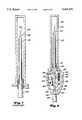
- FIG. 1is an exploded perspective view of a preferred embodiment of the present sharp cover
- FIG. 2is a perspective view of the cover or cap of FIG. 1, positioned to receive the free end of a hypodermic needle through a funnel-shaped sharps guide;
- FIG. 3is a view taken along line 3--3 of FIG. 2;
- FIG. 4is a section view taken along line 4--4 of FIG. 3;
- FIG. 5is a section view similar to FIG. 3, but showing the free end of a needle inserted into the cover;
- FIG. 6is an enlarged partial section view of the cover of FIG. 5 showing a preferred gripper in engagement with a the needle after attempted withdrawal of the needle;
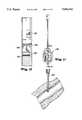
- FIG. 7is a partial section view of a conventional IV catheter kit including a catheter, needle, and needle cover;
- FIG. 8is a partial section view of a new IV catheter having a needle lock or cap according to the present invention.
- FIG. 9is a partial section view of the present IV catheter and needle inserted into a patient.
- FIG. 10is a partial section view thereof with the needle point retracted into the needle lock
- FIG. 11is a partial section view thereof showing the IV catheter remaining in the patient and with the needle locked into the needle lock and detached from the IV catheter;
- FIG. 12is a section view of the needle lock taken along line 12--12 of FIG. 11;
- FIG. 13is a perspective view of another embodiment used in applications where it is desirable to separate the needle from the syringe, after a procedure;
- FIG. 14is an exploded perspective view thereof
- FIG. 15is an enlarged partial section view of a needle inserted into the sliding outer cover, with the splines of the needle hub engaged with the splines of the sliding outer cover of the present safety device;
- FIG. 16is a top view of the sliding outer cover shown in FIGS. 13-15;
- FIG. 17is a section view of the sliding outer cover taken along line 17--17 of FIG. 16;
- FIG. 18is a section view of the sliding outer cover taken along line 18--18 of FIG. 17;
- FIG. 19is a side elevation view of the housing.
- FIG. 20is a side elevation view of an alternative embodiment having a combined spring and seal block.
- a hypodermic syringe and needle assembly 20includes a needle 22 having a free end 24, a restrained end 25, an outer surface 26, and a longitudinal axis 27. Free end 24 has a sharp tip 28 to pierce the skin and/or tissue.
- the cover 10includes a housing 30, a gripping element 70, a biasing element 80, and preferably a sealing element 90.
- the housing 30is advantageously provided as a two-part plastic assembly having a first section 32 and a second section 34.
- the housing 30includes top and bottom ends 36 and 38.
- a sharps receiving portion 100is provided at the top end 36.
- a conical metal liner 101is attached (bonded, snapped or molded-in, etc.) to the receiving portion 100 to prevent sharp instrument tips from sticking into the plastic receiving portion surface.
- the housing 30is also provided with a first set of substantially opposed lateral interior surfaces 40 and 42, an upper interior surface 44 and lower interior surface 46. As best shown in FIG. 4, the housing 30 also includes a second set of substantially opposed lateral interior sidewalls 48 and 50. Lateral interior surfaces 40 and 42 and interior sidewalls 48 and 50 each extend between upper and lower interior surfaces 44 and 46 to define an interior cavity 60. The gripping element 70, biasing element 80 and sealing element 90 are contained within the cavity 60.
- the lateral interior surface 40includes an upper planar portion 52 and lower portion 54. As best shown in FIG. 5 upper planar portion 52 is configured to engage the free end 24 of the needle along tangent 26A upon insertion of free end 24 into the cover 10.
- the lower portion 54defines a recess 62 provided to position the sealing element 90 adjacent the lower interior surface 46. Upon insertion of a needle, the needle tip 28 embeds into the sealing element 90.
- the lateral interior surface 42includes an upper angled portion 56 and a lower planar portion 58.
- the upper angled portion 56 together with upper planar portion 52form a wedging element 64 configured to cooperate with the gripping element 70 before and after insertion of free end 24 of the needle into the cover 10.
- the upper angled portion 56inclines towards the lateral interior surface 40 as the upper angled portion 56 extends from the lower planar portion 58 towards the first end 36 to define an area of convergence or a wedge zone 66.
- the lower planar portion 58is substantially parallel to the upper planar portion 52.
- the gripping element 70is substantially cylindrical in shape, having two flat ends 72 and 74 and a substantially arcuate gripping surface 76. Referring to FIG. 4, the gripping element 70 is positioned within interior cavity 60 with the flat ends 72 and 74 closely adjacent to the interior sidewalls 48 and 50. The distance between sidewalls 72 and 74 is sufficient to permit the gripping element 70 to slide within cavity 60 between the upper and lower interior surfaces 44 and 46, while substantially maintaining its alignment.
- gripping surface 76(vis-a-vis wedging element 64 and the needle) are shown proportionally in the drawings and are selected to ensure that gripping surface 76 (in response to the biasing action of biasing element 80) remains in simultaneous engagement with the upper planar portion 52 and the angled portion 56 before insertion of free end 24 of the needle into the housing 30, and to ensure that gripping surface 76 (in response to the biasing action of biasing element 80) remains in simultaneous engagement with the outer surface 26 of the needle along tangent 26B and angled portion 56 after insertion of the needle into the housing 30.
- the substantially arcuate gripping surface 76facilitates the foregoing described purposes while at the same time ensuring that gripping element 70 does not engage the free end 24 of the needle in such a manner as to prevent free end 24 from being fully inserted into the interior cavity 60 as best shown in FIG. 5. It will be understood by those skilled in the art that other configurations of gripping element 70 may also facilitate these purposes.
- the biasing element 80is an annular shaped elastomer, having two flat ends 82 and 84, a substantially round outer surface 86, with a hole 88 extending between the ends 82 and 84.
- the biasing element 80is positioned within the interior cavity 60, between the gripping element 70 and the sealing element 90, such that its ends 82 and 84 are adjacent the sidewalls 48 and 50 and outer surface 86 engages gripping element 70.
- the outer diameter (uncompressed) of the biasing element 80is sufficiently large to ensure that it constantly acts upon the gripping element 70, urging the gripping element 70 towards the first end 36. This causes the gripping surface 76 to engage the upper planar portion 52 and the angled portion 56 as described above.
- first and second sections 32 and 34 of housing 30are joined together using any conventional methods.
- the interaction between the biasing element 80, the gripping element 70 and the wedging element 64 prior to insertion of free end 24 into interior cavity 60is shown in FIG. 3.
- the biasing element 80exerts an upward force on the gripping element 70. This upward force drives the gripping element 70 into engagement with the upper planar portion 52 and the angled portion 56, effectively wedging the gripping element 70 therebetween.
- the pressure exerted against gripping element 70 at the interface between gripping element 70 and angled portion 56includes a component of force which is perpendicular to the upper planar portion 52. This component of force is offset by an opposing force at the interface between the gripping element 70 and the upper planar portion 52.
- the free end 24 of the needleis inserted into interior cavity 60, it is wedged between the upper planar portion 52 and the gripping element 70 thereby displacing gripping element 70 and causing the gripping element 70 to move downwardly towards the bottom end 38.
- the free end 24is engaged by the upper planar portion 52 along tangent 26A and engaged by the gripping element 70 along tangent 26B.
- the downward motion of gripping element 70causes biasing element 80 to further compress thereby increasing the amount of pressure exerted by the biasing element 80 against the gripping element 70.
- any attempt to withdraw needle 22 from the interior cavity 60 after insertionwill generate opposing frictional forces at the interface between the upper planar portion 52 and free end 24 and at the interface between gripping element 70 and free end 24.
- the frictional force exerted by free end 24 upon gripping element 70will tend to drive gripping element 70 upwardly towards the first end 36 thereby increasing the pressure exerted against the gripping element 70 at the interface between the gripping element 70 and the angled portion 56 which, in turn, will increase the pressure exerted both at the interface between the upper planar portion 52 and free end 24 along tangent 26A and at the interface between the gripping element 70 and free end 24 along tangent 26B, thereby increasing the needle retaining effect of the cover 10.
- the greater the force applied to needle 22 tending to withdraw the free end 24 from the interior cavity 60the greater the frictional forces exerted upon the free end 24 resisting such movement.
- the needletherefore becomes permanently locked within the housing.
- the biasing element 80is selected to allow surgical sharps to be manually inserted into the interior cavity 60 without difficulty while at the same time ensuring that any attempt to withdraw such sharp will be opposed by sufficient frictional forces as described above. While, in the preferred embodiment, the biasing element 80 must be sufficiently large to render the cover 10 operable, the biasing element 80 must not be so large or stiff as to prevent the needle 22 from being inserted into interior cavity sufficiently to ensure that tip 28 fully engages sealing element 90.
- the outer diameter 87 (compressed) of the biasing element 80 as measured in a plane transverse to upper planar portion 52must be less than the distance between the tangent 26B to outer surface 26 and lower planar portion 54.
- the biasing element 80may be positioned within the interior cavity 60 vis-a-vis the gripping element 70 such that the pressure at the interface between gripping element 70 and the biasing element 80 urges the biasing element 80 away from the upper planar portion 52, as shown in FIG. 5.
- biasing element 80may be positioned within the interior cavity 60 vis-a-vis the gripping element 70 such that the pressure at the interface between gripping element 70 and the biasing element 80 urges the biasing element 80 away from the upper planar portion 52, as shown in FIG. 5.
- biasing element 80may be positioned within the interior cavity 60 vis-a-vis the gripping element 70 such that the pressure at the interface between gripping element 70 and the biasing element 80 urges the biasing element 80 away from the upper planar portion 52, as shown in FIG. 5.
- alternative configurations, compositions and placements of biasing element 80are possible and that alternative means may be employed to ensure that biasing element 80 does not unduly impede insertion of free end 24 into foil 10.
- the needle retaining effect of the foregoing describe designis enhanced by the provision, on the gripping surface 76, of a plurality of evenly-spaced teeth 78, each of which extends between ends 72 and 74.
- the teeth 78provide sharp edges 79 and are backwardly curving, as best shown in FIG. 6, to improve the gripping characteristics of the gripping surface 76.
- the teeth 78 (and the rest of gripping element 70)are preferably composed of a material which is hard enough to gouge the outer surface 26 of free end 24. As a result, attempts to withdraw the needle 22 from interior cavity 60 drive the teeth 78 into the outer surface 26 thereby creating a mechanical interference which precludes withdrawal of the needle 24. The free end 24 of the needle 22 is thus permanently locked into the cover 10.
- the gripping surface 76 and upper planar portion 52may, alternatively, be roughened or scored to improve the needle retaining effect.
- the cover 10is also provided with sealing element 90.
- the sealing element 90is a slab of material which is sufficiently soft to allow penetration of tip 28 into the sealing element 90 while at the same time providing a proper seal of the needle tip.
- the sealing element 90is sized to complement the lower interior surface 40 and to reside with the recess 62.
- the needle port 108is positioned over the sealing element 90, so that the needle tip will project into the sealing element.
- the housing 30is provided with a sharps receiving portion 100 at its first end 36.
- the sharps receiving portion 100includes sharps guide 102 having a funnel-shaped recess with a maximum diameter 104 on the top end 36 and a minimum diameter 106 at the bottom of the funnel-shaped recess.
- the minimum diameter 106defines an eccentric needle port 108 which is sized to receive the free end 24 of a needle 22.
- the needle port 108is positioned such that upper planar surface 52 is tangent to the outer diameter of needle port 108.
- the free end 24 of the needlecan accordingly be placed through the needle port 108 without difficulty while simultaneously being properly positioned within the interior cavity 60 between the upper planar portion 52 and the gripping element 70.
- a plurality of covers 10may be mounted in an array on a flat bottom container which can be placed on a surgical table, cart, etc.
- the bottom end 38 of each cover 10may be attached to the container, using any suitable means, so that the sharps receiving portion 100 of each cover 10 is directed substantially upward.
- the containermay present the sharps receiving portions 100 at an angle to the horizontal.
- the bottom of the covers containermay be provided with an adhesive or other suitable means to resist unwanted movement during use.
- a safety catheterhaving similar advantages. As shown in FIG. 7, a needle 122 is surrounded by a conventional IV catheter 120, and covered by a removable needle cap 124. A male fitting 126 on the needle 122 typically engages a female fitting 128 (e.g. a Luer fitting) on the catheter 120, as is well known in the art.
- a female fitting 128e.g. a Luer fitting
- the cap 124is first removed to expose the point 125 of the needle 122.
- the needle point 125is used to puncture the patient's skin, and the needle 122 and catheter 120 are then slowly pushed into the puncture site.
- the catheter 120is then held in place within the puncture site while the needle is withdrawn.
- the catheterremains in the patient, and is connected to an IV tube.
- the needleposes a needle stick hazard until it is properly disposed of.
- the present safety cathetergreatly reduces the needle stick hazard associated with IV catheters.
- the present safety catheterincludes an IV catheter 130 and needle cap 134, which may be the same as the conventional catheter and needle cover shown in FIG. 7.
- the IV catheter 130is fitted onto a needle lock 138 having a housing 140.
- the outer surface of the housing 140may be smooth or knurled.
- the housing 140has a polygonal shape which includes two tapered surfaces 142. These tapered surfaces 142 provide thumb and finger surfaces for grabbing and holding the housing 140 in place.
- the housing 140includes a fitting 144 similar to the fitting 126 of the conventional catheter needle shown in FIG. 7, for joining the housing 140 and IV catheter 130.
- a stay 160projects from the housing wall and contacts a needle 132 which extends entirely through the housing 140 and IV catheter 130.
- An inner wall 147slants toward the needle 132 at the top of the housing (The safety catheter in FIG. 8 is shown inverted).
- the needle 132may be similar to, but is longer than the needle 122 shown in FIG. 7.
- a cam 148 within the housing 140includes a lower leg 156 and an upper leg 158, and pivots on a pin 154.
- the width of lower leg 156is approximately the same as the interior space 146 within the housing 140.
- the upper leg 158is about one half as wide or thick as the lower leg, so that the needle 132 may extend underneath the upper leg 158.
- the full width of the lower leg 156prevents the needle 132 from extending into the opening 151, unless the cam is positioned out of the way, as shown in FIG. 8.
- a gripping wheel 150is positioned within the housing 140 between the upper leg 158 of the cam 148, the housing wall, and a spring 152.
- the gripping wheel 150is formed of metal, hard plastic, or other substantially non-compressible material.
- the perimeter of the wheel 150is knurled, roughened or serrated.
- the wheel 150is too wide to pass underneath the upper leg 158 of the cam 148.
- the spring 152positioned within a spring bore in the housing, pushes the wheel 150 against the upper leg 158.
- the gripping wheel 150itself is not attached to any portion of the housing 140. Rather, it is held in place by the spring 152, the upper leg 158 and the housing wall, and can shift position.
- the spring 152pushes against the gripping wheel 150.
- the spring forcepresses the gripping wheel against the upper leg 158 of the cam 148, causing the cam 148 to rotate about pivot 154 in a clockwise direction, until the lower arm 156 contacts the needle 132 and presses against it.
- a slight frictional forceis thus created between the cam 148, the stay 160, and the needle 132, which helps to prevent the needle 132 from prematurely backing out of the needle lock.
- the needle cover 134is first removed to expose the needle 132.
- the needle and catheterare then inserted into a patient's arm 155 or other body area, as with conventional IV catheter kits, as shown in FIG. 9.
- the needle lock housing 140is held preferably by clasping the tapered surfaces 142 of the housing between the thumb and forefinger of one hand. With the housing held in place, the needle 132 is withdrawn from the catheter 130.
- the cathetermay optionally be taped down onto the skin.
- the knurled perimeter of the wheel 150grips the shaft of the needle 132 and the slanted wall 147, preventing the wheel from turning counter clockwise. As the wheel is engaged to both the needle shaft and the wall 147 and cannot turn, the needle 132 cannot be pulled any farther out of the housing. (The geometry allows the wheel to turn or roll clockwise, allowing the needle to be pushed further through the housing, but not counter clockwise, which would allow the needle to be withdrawn.) After the wheel 150 wedges into position as shown in FIG. 10, the cam 148 is prevented from pivoting in a counter-clockwise direction, to release the needle point 135, as the wedged wheel 150 blocks movement of the upper leg 158.
- the lower leg 156is locked in a position which blocks the opening 151 preventing the needle 132 from being pushed out of the housing 140, and the wedged wheel prevents the needle from being pulled out of the housing.
- the needleis therefore locked in position.
- the upper leg 158prevents the wheel from shifting up into the wedged position, as shown in FIG. 8.
- the point of the needleis safely contained within the housing 140.
- the cam 148 and gripping wheel 150prevent the needle from either being pulled out of or pushed through the housing 140.
- the point of the needleis securely and permanently held within the housing reducing the possibility of injury caused by contact with the used needle.
- the fitting on the housing 140may be disengaged from the catheter 130 and an IV connected.
- the disengaged needle 132 and needle lock 138may then be safely disposed of, without replacing the needle cap 134.
- the present embodimenttherefore provides a safe, efficient and self-contained catheter for protecting the points of used IV needles.
- the needle lock 138works automatically with the withdrawal of the needle from the IV puncture site. Even if the needle is pulled out of the puncture site very quickly or forcefully, the point 135 will still become locked within the housing 140.
- the needle lock 138permits medical personnel to simply insert the needle and catheter, withdraw the needle, and immediately dispose of the used needle without substantial risk of injury, and without the taking of time and risks of recapping or other steps.
- the needle lock 138can be used with standard existing catheters. Standard needles may also be used, if they are long enough to extend through both the catheter 130 and needle lock 138.
- the needle lock 138is also highly tamper resistant. Once the needle 132 becomes locked within the housing 140, it is exceptionally difficult or impossible to remove the needle.
- the housing 140is made with a thin, flat profile, so that the housing 140 may be laid flat against the patient's skin while the catheter is inserted.
- the housing 140should be compact and made of a tough material, preferably metal or a hard plastic.
- the openings in the housing 140 through which the needle 132 passesshould be made to approximate the diameter of the needle itself, to insure that the needle is securely held within the housing 140.
- a hypodermic syringe and needle assembly 200in certain procedures, such as blood gas sampling, blood is withdrawn with a hypodermic syringe and needle assembly 200.
- the needle 204rather than discarding the entire needle assembly 200 (as is often the case in giving injections), the needle 204 must be removed from the syringe 202.
- the shaft 206 of the needle 204is often very short, there may be little space for the medical technician's fingers to grasp, turn and remove the needle 204 after the shaft 206 of the needle 204 is fully inserted into a safety device, such as the housing 30 shown in FIG. 2.
- a safety device 220has an outer cover 222 slidably positioned over a housing 240.
- the cover 222has longitudinal ribs 224 around its outside circumference.
- An opening 226 at the top or front of the cover 222has splines 228 which taper inwardly along a conically tapering inner surface 232.
- the cover 222has a housing slot 230, to provide clearance for a ridge section 278 on the housing 240, when the cover is positioned fully over the housing 240, as shown in FIG. 13.
- the housing 240has a conical dish surface 242 having a metal liner 244 attached (e.g., bonded shaped or molded in) to the dish surface 242.
- a needle opening 246extends through the center of the dish surface 242 and liner 244.
- the housing 240has a chassis slot 250 on one side, with a tab slot 252 above the chassis slot 250.
- a chassis 260(preferably molded as a single plastic unit) has a tab 262, a straight wall 274 and an inclined wall 272, in part forming a wheel recess 268.
- a gripping wheel 264is positioned within the wheel recess 268.
- a spring 266is supported within a spring slot 270 formed by internal chassis walls.
- the gripper wheel 264is preferably a steel wheel having a knurled or roughened surface around its circumference (e.g., a cigarette lighter wheel).
- the spring 266is advantageously a soft rubber block.
- a seal block 276is contained within the chassis 260 and held in place by chassis walls.
- the seal blockis preferably a soft rubber or plastic material.
- the spring 266 and seal block 276are combined as a single integral piece, with the spring 266 formed as a protrusion on the block 276, as shown in FIG. 20.
- the chassis 260has a top wall 263 having a needle entry opening 265 adjacent to the straight wall 274. With the chassis 260, housing 240 and cover 222 assembled and ready for use, as shown in FIG.
- the opening 226 in the cover 222; the opening 246 in the housing 240; and the opening 265 in the chassis,are aligned, so the needle point 210 can pass freely through them, in between the straight wall 274 and the gripping wheel 264, and into the sealing block 276.
- the substantially impenetrable lower wall 267 of the chassis 260prevents the point 210 from piercing through the chassis.
- a recess 234is formed on the inside of the cover 222 above the housing slot 230, and is adapted to receive the tab 262 on the chassis 260.
- the cover 222is provided with splines 228 preferably matching the number of splines 212 on the hub 208 of the needle 204 (FIG. 13).
- the splines 228, as shown in FIGS. 13, 16, 17 and 18,are spaced apart and oriented to properly intermesh with the splines 212 on the needle hub 208.
- Typical needles 204have 4 splines 212.
- the cover 222is also provided with 4 splines 228, although other numbers and configurations may be provided to work with different needles.
- the point 210 of the needle 204is inserted through the opening 226 in the cover 222, through the needle opening 246, and into the chassis 260 wherein it is engaged and locked by the interaction of the wheel 264, spring 266, straight wall 274 and inclined wall 272, as described above in connection with e.g., FIGS. 3, 4 and 5.
- the device 220is preferably held in a tray or other fixture during needle insertion, to keep hands away from the needle point. Referring to FIG. 13, with the needle 204 fully inserted, there is little or no clearance between the hub 208 of the needle 204 and the front or top surface 223 of the cover 222.
- the cover 222can be moved upwardly along the shaft 206 of the needle 204, while the housing 240 remains around and captivates the point 210 of the needle 204 towards the hub 212.
- the splines 228 and tapered surface or inlet 232 on the cover 222are configured to match and engage the hub 208 and its splines 212.
- the cover 222With the cover 222 engaged onto the hub 208, the cover may be turned (counterclockwise) to unwind the hub 208 from the syringe threads 214 at the lower end of the syringe 202. Accordingly, the needle 204 (i.e., the hub 208 and shaft 206) may be separated from the syringe 202 while the point 210 of the needle 204 is captive within the housing 240, to avoid accidental needle sticks.
- the cover 222may engage the needle hub 208, even before the point 210 bottoms out in the seal block 276. In this instance, the cover 222 need not (and cannot) be slid towards the syringe 202 to engage the hub 208. Rather, the needle 204 is unwound simply by holding the syringe 202 and turning the cover 222 (with the housing 240 containing the chassis 260 turning with the cover 222). On the other hand, if the shaft 206 of the needle 204 is longer, the point 210 will bottom out within the seal block 276 while the hub 208 is spaced away from the cover 222.
- the cover 222is pushed up the along the needle shaft to engage the hub 208. If the needle shaft 206 is exceptionally long, the cover 222 will be moved far enough that it comes completely off of the housing 240, which remains around the point 210. Whether this occurs or not does not affect the operation of the device 220, as the needle 204 is still readily unwound from the syringe 202 while the point 210 is captive in the housing 240. In addition, as the cover 222 cannot fit over the hub 208, after the syringe 202 is separated from the needle 204, the needle 204, cover 222 and housing 240 necessarily remain together.
- the tab 262 on the chassis 260fits within the recess 234 on the cover 222, to act as an additional anti-rotation device between the cover 222 and the housing 240 (in addition to the interaction of the bridge 278 against the side walls of the housing slot 230 on the cover 222) although whether the housing 240 turns with the cover 222 when the needle 204 is unwound, does not affect performance of the device 220.
- Embodiments having pairs of gripping elements, separated by a spring or biasing elementcan also be used. With minor modifications, various sharps can be accommodated, such as flat blades, angled or curved blades or needles, etc., as equivalents to the described embodiments. Accordingly, the scope of the present invention should not be limited to the specific embodiments illustrated, but is limited only by the following claims and their equivalents.
Landscapes
- Health & Medical Sciences (AREA)
- Engineering & Computer Science (AREA)
- Life Sciences & Earth Sciences (AREA)
- Anesthesiology (AREA)
- General Health & Medical Sciences (AREA)
- Biomedical Technology (AREA)
- Heart & Thoracic Surgery (AREA)
- Hematology (AREA)
- Veterinary Medicine (AREA)
- Animal Behavior & Ethology (AREA)
- Public Health (AREA)
- Vascular Medicine (AREA)
- Environmental & Geological Engineering (AREA)
- Biophysics (AREA)
- Pulmonology (AREA)
- Infusion, Injection, And Reservoir Apparatuses (AREA)
- Media Introduction/Drainage Providing Device (AREA)
- Materials For Medical Uses (AREA)
Abstract
Description
Claims (17)
Priority Applications (7)
| Application Number | Priority Date | Filing Date | Title |
|---|---|---|---|
| US08/583,989US5601532A (en) | 1993-07-20 | 1996-01-11 | Locking safety cover for sharp instruments |
| EP96902736AEP0806971A1 (en) | 1995-01-23 | 1996-01-22 | Safety catheter |
| CA002210716ACA2210716A1 (en) | 1995-01-23 | 1996-01-22 | Safety catheter |
| PCT/US1996/000750WO1996022800A1 (en) | 1995-01-23 | 1996-01-22 | Safety catheter |
| AU47030/96AAU4703096A (en) | 1995-01-23 | 1996-01-22 | Safety catheter |
| IL11790496AIL117904A0 (en) | 1995-06-07 | 1996-04-15 | Safety device |
| MXPA/A/1997/005560AMXPA97005560A (en) | 1995-01-23 | 1997-07-22 | Catheter of seguri |
Applications Claiming Priority (4)
| Application Number | Priority Date | Filing Date | Title |
|---|---|---|---|
| US08/094,842US5417659A (en) | 1993-07-20 | 1993-07-20 | Surgical instrument sharp end foil |
| US08/376,399US5533974A (en) | 1993-07-20 | 1995-01-23 | Locking safety cover for sharp instruments |
| US08/472,553US5584809A (en) | 1993-07-20 | 1995-06-07 | Safety catheter |
| US08/583,989US5601532A (en) | 1993-07-20 | 1996-01-11 | Locking safety cover for sharp instruments |
Related Parent Applications (1)
| Application Number | Title | Priority Date | Filing Date |
|---|---|---|---|
| US08/472,553Continuation-In-PartUS5584809A (en) | 1993-07-20 | 1995-06-07 | Safety catheter |
Publications (1)
| Publication Number | Publication Date |
|---|---|
| US5601532Atrue US5601532A (en) | 1997-02-11 |
Family
ID=27409298
Family Applications (1)
| Application Number | Title | Priority Date | Filing Date |
|---|---|---|---|
| US08/583,989Expired - LifetimeUS5601532A (en) | 1993-07-20 | 1996-01-11 | Locking safety cover for sharp instruments |
Country Status (5)
| Country | Link |
|---|---|
| US (1) | US5601532A (en) |
| EP (1) | EP0806971A1 (en) |
| AU (1) | AU4703096A (en) |
| CA (1) | CA2210716A1 (en) |
| WO (1) | WO1996022800A1 (en) |
Cited By (41)
| Publication number | Priority date | Publication date | Assignee | Title |
|---|---|---|---|---|
| USD392014S (en) | 1997-04-04 | 1998-03-10 | Bore Tech, Inc. | Gun cleaning patch and solvent collector |
| US5810167A (en)* | 1996-07-31 | 1998-09-22 | Nissho Corporation | Infectious waste container for blood collection needles |
| US20020099383A1 (en)* | 2001-01-25 | 2002-07-25 | Linvatec Corporation | Storage package for coring reamer assembly |
| US20020115987A1 (en)* | 2001-02-16 | 2002-08-22 | Path | Needle cannula removal by extraction |
| US20030100868A1 (en)* | 2001-03-15 | 2003-05-29 | Ferguson F. Mark | Safety shield for medical needles |
| USD476742S1 (en) | 2002-07-22 | 2003-07-01 | Becton, Dickinson And Company | Needle holder |
| US20030195475A1 (en)* | 2001-03-15 | 2003-10-16 | Ferguson F. Mark | Safety shield for medical needles |
| US20040078003A1 (en)* | 2001-03-15 | 2004-04-22 | Smith Daniel K. | Resettable safety shield for medical needles |
| US20040092888A1 (en)* | 2001-03-15 | 2004-05-13 | Ferguson F. Mark | Safety shield for medical needles |
| US20040092889A1 (en)* | 2002-11-07 | 2004-05-13 | Ferguson F. Mark | Safety shield for medical needles |
| US20040171989A1 (en)* | 2001-03-15 | 2004-09-02 | Horner Shawn K. | Biopsy needle device |
| US6811547B2 (en) | 2002-07-22 | 2004-11-02 | Becton, Dickinson & Company | Needle shielding assembly |
| US20050043691A1 (en)* | 2001-03-15 | 2005-02-24 | Ferguson F. Mark | Safety shield for medical needles |
| US20050182362A1 (en)* | 2004-02-17 | 2005-08-18 | Medex, Inc. | Needle guards |
| US7144360B2 (en)* | 2004-12-22 | 2006-12-05 | Knelson Patents Inc. | Centrifugal separator with a separate strip insert mounted in the bowl |
| US20070038183A1 (en)* | 2005-08-08 | 2007-02-15 | Bialecki Dennis M | Needle guard clip with stylus |
| US20070038188A1 (en)* | 2005-08-08 | 2007-02-15 | Bialecki Dennis M | Duckbill catheter release mechanism |
| US20070038184A1 (en)* | 2005-08-08 | 2007-02-15 | Bialecki Dennis M | Needle guard clip with lip |
| US20070073222A1 (en)* | 2005-08-08 | 2007-03-29 | Lilley Thomas F Jr | Needle guard mechanism with angled strut wall |
| US20070106231A1 (en)* | 2003-11-25 | 2007-05-10 | Snow Jeremy K | Resettable safety shield for medical needles |
| US20070191776A1 (en)* | 2006-02-16 | 2007-08-16 | Medex, Inc. | Enclosed Needle Device with Duckbill Release Mechanism |
| US20080011640A1 (en)* | 2004-02-12 | 2008-01-17 | Medtronic Vascular, Inc. | Packaged System Including a Protective Housing for a Treatment Device Carried on a Catheter |
| US20080021387A1 (en)* | 2005-08-31 | 2008-01-24 | Rodolfo Gaba | Medical Sharps Retardation Apparatus and a Method of Retarding Medical Sharps from Future Use |
| US7413562B2 (en) | 2001-03-15 | 2008-08-19 | Specialized Health Products, Inc. | Safety shield for medical needles |
| US20090157013A1 (en)* | 2007-11-21 | 2009-06-18 | Becton, Dickinson And Company | Needle safety device |
| US20090216201A1 (en)* | 2007-11-21 | 2009-08-27 | Becton, Dickinson And Company | Safety Needle Guard |
| US7624864B1 (en) | 2005-04-08 | 2009-12-01 | Medvision, Inc. | Permanent sharps capture devices, systems and methods of use |
| US20100122925A1 (en)* | 2008-11-18 | 2010-05-20 | Joan Charbonneau | Syringe disposal unit |
| US7985216B2 (en) | 2004-03-16 | 2011-07-26 | Dali Medical Devices Ltd. | Medicinal container engagement and automatic needle device |
| US8376998B2 (en) | 2003-09-17 | 2013-02-19 | Elcam Medical Agricultural Cooperative Association Ltd. | Automatic injection device |
| US8486024B2 (en) | 2011-04-27 | 2013-07-16 | Covidien Lp | Safety IV catheter assemblies |
| US8591467B2 (en) | 2011-07-25 | 2013-11-26 | Covidien Lp | Vascular access assembly and safety device |
| US8628497B2 (en) | 2011-09-26 | 2014-01-14 | Covidien Lp | Safety catheter |
| US8715250B2 (en) | 2011-09-26 | 2014-05-06 | Covidien Lp | Safety catheter and needle assembly |
| US8834422B2 (en) | 2011-10-14 | 2014-09-16 | Covidien Lp | Vascular access assembly and safety device |
| US8939938B2 (en) | 2006-10-12 | 2015-01-27 | Covidien Lp | Needle tip protector |
| US9555221B2 (en) | 2014-04-10 | 2017-01-31 | Smiths Medical Asd, Inc. | Constant force hold tip protector for a safety catheter |
| US10457578B1 (en) | 2018-06-22 | 2019-10-29 | Gary McInnis | Automated sulfur burner for agricultural irrigation |
| US12017011B2 (en) | 2019-09-10 | 2024-06-25 | Medsource International Llc | Intravenous catheter device |
| US12186497B2 (en) | 2022-01-14 | 2025-01-07 | Medsource International Llc | Intravenous cannula |
| US12337123B2 (en) | 2021-05-06 | 2025-06-24 | Medsource Labs, Llc | Safety intravenous cannula |
Families Citing this family (14)
| Publication number | Priority date | Publication date | Assignee | Title |
|---|---|---|---|---|
| US5853393A (en)* | 1995-06-07 | 1998-12-29 | Johnson & Johnson Medical, Inc. | Catheter needle locking and catheter hub unlocking mechanism |
| US5882337A (en)* | 1995-06-07 | 1999-03-16 | Johnson & Johnson Medical, Inc. | Tip protection device |
| WO1999015222A1 (en)* | 1997-09-23 | 1999-04-01 | Becton Dickinson And Company | Eccentric rotary high pressure seal |
| EP1344544A4 (en)* | 2000-12-18 | 2008-09-03 | Terumo Corp | Protector and storage needle assembly |
| US7226434B2 (en) | 2003-10-31 | 2007-06-05 | Tyco Healthcare Group Lp | Safety shield |
| US7988664B2 (en) | 2004-11-01 | 2011-08-02 | Tyco Healthcare Group Lp | Locking clip with trigger bushing |
| FR2867081B1 (en)* | 2004-03-02 | 2006-05-26 | Vygon | SLIDING SAFETY DEVICE FOR PLACING A CANNULA INTO A VEIN |
| US7905857B2 (en) | 2005-07-11 | 2011-03-15 | Covidien Ag | Needle assembly including obturator with safety reset |
| US7850650B2 (en) | 2005-07-11 | 2010-12-14 | Covidien Ag | Needle safety shield with reset |
| US7828773B2 (en) | 2005-07-11 | 2010-11-09 | Covidien Ag | Safety reset key and needle assembly |
| US20060276747A1 (en) | 2005-06-06 | 2006-12-07 | Sherwood Services Ag | Needle assembly with removable depth stop |
| WO2009042874A1 (en) | 2007-09-27 | 2009-04-02 | Tyco Healthcare Group Lp | I.v. catheter assembly and needle safety device |
| US8357104B2 (en) | 2007-11-01 | 2013-01-22 | Coviden Lp | Active stylet safety shield |
| US20210187250A1 (en)* | 2019-12-18 | 2021-06-24 | Becton, Dickinson And Company | Inhibiting fluid leakage and splatter in catheter devices and systems |
Citations (3)
| Publication number | Priority date | Publication date | Assignee | Title |
|---|---|---|---|---|
| US4995871A (en)* | 1988-02-04 | 1991-02-26 | Snow Brand Milk Products Co., Ltd. | Needle detacher for syringe |
| US5187850A (en)* | 1987-04-22 | 1993-02-23 | Mccammon John W | Needle disposal system |
| US5417659A (en)* | 1993-07-20 | 1995-05-23 | Devon Industries, Inc. | Surgical instrument sharp end foil |
Family Cites Families (4)
| Publication number | Priority date | Publication date | Assignee | Title |
|---|---|---|---|---|
| US4747831A (en) | 1987-04-29 | 1988-05-31 | Phase Medical, Inc. | Cannula insertion set with safety retracting needle |
| ES2081973T3 (en) | 1989-02-01 | 1996-03-16 | Sero Guard Corp | AUTOMATIC DISPOSABLE HYPODERMIC NEEDLE PROTECTOR. |
| US5195983A (en)* | 1991-08-27 | 1993-03-23 | Penta Associates | Syringe guard and disposal system |
| US5334158A (en)* | 1993-12-20 | 1994-08-02 | Mclees Donald J | Automatic needle tip guard for standard hypodermic needles |
- 1996
- 1996-01-11USUS08/583,989patent/US5601532A/ennot_activeExpired - Lifetime
- 1996-01-22WOPCT/US1996/000750patent/WO1996022800A1/ennot_activeApplication Discontinuation
- 1996-01-22CACA002210716Apatent/CA2210716A1/ennot_activeAbandoned
- 1996-01-22EPEP96902736Apatent/EP0806971A1/ennot_activeWithdrawn
- 1996-01-22AUAU47030/96Apatent/AU4703096A/ennot_activeAbandoned
Patent Citations (3)
| Publication number | Priority date | Publication date | Assignee | Title |
|---|---|---|---|---|
| US5187850A (en)* | 1987-04-22 | 1993-02-23 | Mccammon John W | Needle disposal system |
| US4995871A (en)* | 1988-02-04 | 1991-02-26 | Snow Brand Milk Products Co., Ltd. | Needle detacher for syringe |
| US5417659A (en)* | 1993-07-20 | 1995-05-23 | Devon Industries, Inc. | Surgical instrument sharp end foil |
Cited By (79)
| Publication number | Priority date | Publication date | Assignee | Title |
|---|---|---|---|---|
| US5810167A (en)* | 1996-07-31 | 1998-09-22 | Nissho Corporation | Infectious waste container for blood collection needles |
| USD392014S (en) | 1997-04-04 | 1998-03-10 | Bore Tech, Inc. | Gun cleaning patch and solvent collector |
| US6857520B2 (en)* | 2001-01-25 | 2005-02-22 | Linvatec Corporation | Storage package for coring reamer assembly |
| US20020099383A1 (en)* | 2001-01-25 | 2002-07-25 | Linvatec Corporation | Storage package for coring reamer assembly |
| US7537597B2 (en)* | 2001-01-25 | 2009-05-26 | Linvatec Corporation | Storage package for coring reamer assembly |
| US20050090830A1 (en)* | 2001-01-25 | 2005-04-28 | Linvatec Corporation | Storage package for coring reamer assembly |
| US20020115987A1 (en)* | 2001-02-16 | 2002-08-22 | Path | Needle cannula removal by extraction |
| US7357784B2 (en) | 2001-03-15 | 2008-04-15 | Specialized Health Products Inc. | Safety shield for medical needles |
| US9539398B2 (en) | 2001-03-15 | 2017-01-10 | Specialized Health Products, Inc. | Safety shield for medical needles |
| US20030100868A1 (en)* | 2001-03-15 | 2003-05-29 | Ferguson F. Mark | Safety shield for medical needles |
| US20040171989A1 (en)* | 2001-03-15 | 2004-09-02 | Horner Shawn K. | Biopsy needle device |
| US6796962B2 (en) | 2001-03-15 | 2004-09-28 | Specialized Health Products, Inc. | Safety shield for medical needles |
| US20040092888A1 (en)* | 2001-03-15 | 2004-05-13 | Ferguson F. Mark | Safety shield for medical needles |
| US20040236289A1 (en)* | 2001-03-15 | 2004-11-25 | Ferguson F. Mark | Safety shield for medical needles |
| US20040078003A1 (en)* | 2001-03-15 | 2004-04-22 | Smith Daniel K. | Resettable safety shield for medical needles |
| US7618395B2 (en) | 2001-03-15 | 2009-11-17 | Specialized Health Products, Inc. | Methods for shielding medical needles |
| US20050059937A1 (en)* | 2001-03-15 | 2005-03-17 | Ferguson F. Mark | Safety shield for medical needles |
| US20050070855A1 (en)* | 2001-03-15 | 2005-03-31 | Ferguson F Mark | Safety shield for medical needles |
| US20030195475A1 (en)* | 2001-03-15 | 2003-10-16 | Ferguson F. Mark | Safety shield for medical needles |
| US6902546B2 (en) | 2001-03-15 | 2005-06-07 | Specialized Health Products, Inc. | Safety shield for medical needles |
| US20050043691A1 (en)* | 2001-03-15 | 2005-02-24 | Ferguson F. Mark | Safety shield for medical needles |
| US6984213B2 (en) | 2001-03-15 | 2006-01-10 | Specialized Health Products, Inc. | Biopsy needle device |
| US7004927B2 (en) | 2001-03-15 | 2006-02-28 | Specialized Health Products, Inc. | Safety shield for medical needles |
| US7008402B2 (en) | 2001-03-15 | 2006-03-07 | Specialized Health Products, Inc. | Safety shield for medical needles |
| US7413562B2 (en) | 2001-03-15 | 2008-08-19 | Specialized Health Products, Inc. | Safety shield for medical needles |
| US7341573B2 (en) | 2001-03-15 | 2008-03-11 | Specialized Health Products Inc. | Safety shield for medical needles |
| US7611485B2 (en) | 2001-03-15 | 2009-11-03 | C. R. Bard, Inc. | Safety shield for medical needles |
| US8845584B2 (en) | 2001-03-15 | 2014-09-30 | Specialized Health Products, Inc. | Safety shield for medical needles |
| US7179244B2 (en) | 2001-03-15 | 2007-02-20 | Specialized Health Products, Inc. | Resettable safety shield for medical needles |
| US6811547B2 (en) | 2002-07-22 | 2004-11-02 | Becton, Dickinson & Company | Needle shielding assembly |
| USD476742S1 (en) | 2002-07-22 | 2003-07-01 | Becton, Dickinson And Company | Needle holder |
| US20040092889A1 (en)* | 2002-11-07 | 2004-05-13 | Ferguson F. Mark | Safety shield for medical needles |
| US7458954B2 (en) | 2002-11-07 | 2008-12-02 | Specialized Health Products, Inc. | Safety shield for medical needles |
| US11623051B2 (en) | 2003-09-17 | 2023-04-11 | E3D Agricultural Cooperative Association Ltd. | Automatic injection device |
| US8376998B2 (en) | 2003-09-17 | 2013-02-19 | Elcam Medical Agricultural Cooperative Association Ltd. | Automatic injection device |
| EP2650033A2 (en) | 2003-09-17 | 2013-10-16 | Elcam Medical Agricultural Cooperative Association Ltd. | Automatic injection device |
| US20070106231A1 (en)* | 2003-11-25 | 2007-05-10 | Snow Jeremy K | Resettable safety shield for medical needles |
| US8096973B2 (en) | 2003-11-25 | 2012-01-17 | Specialized Health Products, Inc. | Resettable safety shield for medical needles |
| US20080011640A1 (en)* | 2004-02-12 | 2008-01-17 | Medtronic Vascular, Inc. | Packaged System Including a Protective Housing for a Treatment Device Carried on a Catheter |
| US8794437B2 (en)* | 2004-02-12 | 2014-08-05 | Medtronic Vascular, Inc. | Packaged system including a protective housing for a treatment device carried on a catheter |
| US20050182362A1 (en)* | 2004-02-17 | 2005-08-18 | Medex, Inc. | Needle guards |
| US7513888B2 (en) | 2004-02-17 | 2009-04-07 | Smiths Medical Asd, Inc. | Needle guards |
| US7985216B2 (en) | 2004-03-16 | 2011-07-26 | Dali Medical Devices Ltd. | Medicinal container engagement and automatic needle device |
| US7144360B2 (en)* | 2004-12-22 | 2006-12-05 | Knelson Patents Inc. | Centrifugal separator with a separate strip insert mounted in the bowl |
| US7624864B1 (en) | 2005-04-08 | 2009-12-01 | Medvision, Inc. | Permanent sharps capture devices, systems and methods of use |
| US20070073222A1 (en)* | 2005-08-08 | 2007-03-29 | Lilley Thomas F Jr | Needle guard mechanism with angled strut wall |
| US20070038182A1 (en)* | 2005-08-08 | 2007-02-15 | Bialecki Dennis M | Needle guard mechanism with needle support |
| US20070038184A1 (en)* | 2005-08-08 | 2007-02-15 | Bialecki Dennis M | Needle guard clip with lip |
| US7632243B2 (en) | 2005-08-08 | 2009-12-15 | Smiths Medical Asd, Inc. | Duckbill catheter release mechanism |
| US20070038179A1 (en)* | 2005-08-08 | 2007-02-15 | Bialecki Dennis M | Needle guard strut wall clip |
| US20070038183A1 (en)* | 2005-08-08 | 2007-02-15 | Bialecki Dennis M | Needle guard clip with stylus |
| US7753877B2 (en) | 2005-08-08 | 2010-07-13 | Smiths Medical Asd, Inc. | Needle guard strut wall clip |
| US20070038188A1 (en)* | 2005-08-08 | 2007-02-15 | Bialecki Dennis M | Duckbill catheter release mechanism |
| US8403886B2 (en) | 2005-08-08 | 2013-03-26 | Smiths Medical Asd, Inc. | Needle guard clip with lip |
| US8647301B2 (en) | 2005-08-08 | 2014-02-11 | Smiths Medical Asd, Inc. | Safety catheter device with removably attached housing |
| US8162881B2 (en) | 2005-08-08 | 2012-04-24 | Smiths Medical Asd, Inc. | Needle guard mechanism with angled strut wall |
| US20070073221A1 (en)* | 2005-08-08 | 2007-03-29 | Bialecki Dennis M | Needle guard mechanism with leaf spring |
| US7984805B2 (en)* | 2005-08-31 | 2011-07-26 | Griff Industries Inc | Medical sharps retardation apparatus and a method of retarding medical sharps from future use |
| US20080021387A1 (en)* | 2005-08-31 | 2008-01-24 | Rodolfo Gaba | Medical Sharps Retardation Apparatus and a Method of Retarding Medical Sharps from Future Use |
| US20070191776A1 (en)* | 2006-02-16 | 2007-08-16 | Medex, Inc. | Enclosed Needle Device with Duckbill Release Mechanism |
| US7658725B2 (en) | 2006-02-16 | 2010-02-09 | Smiths Medical Asd, Inc. | Enclosed needle device with duckbill release mechanism |
| US8939938B2 (en) | 2006-10-12 | 2015-01-27 | Covidien Lp | Needle tip protector |
| US9278180B2 (en) | 2007-11-21 | 2016-03-08 | Becton, Dickinson And Company | Needle safety device |
| US8298180B2 (en) | 2007-11-21 | 2012-10-30 | Becton, Dickinson And Company | Safety needle guard |
| US20090157013A1 (en)* | 2007-11-21 | 2009-06-18 | Becton, Dickinson And Company | Needle safety device |
| US20090216201A1 (en)* | 2007-11-21 | 2009-08-27 | Becton, Dickinson And Company | Safety Needle Guard |
| US20100122925A1 (en)* | 2008-11-18 | 2010-05-20 | Joan Charbonneau | Syringe disposal unit |
| US8486024B2 (en) | 2011-04-27 | 2013-07-16 | Covidien Lp | Safety IV catheter assemblies |
| US8926563B2 (en) | 2011-04-27 | 2015-01-06 | Covidien Lp | Safety IV catheter assemblies |
| US8591467B2 (en) | 2011-07-25 | 2013-11-26 | Covidien Lp | Vascular access assembly and safety device |
| US8628497B2 (en) | 2011-09-26 | 2014-01-14 | Covidien Lp | Safety catheter |
| US9375552B2 (en) | 2011-09-26 | 2016-06-28 | Covidien Lp | Safety needle assembly |
| US8715250B2 (en) | 2011-09-26 | 2014-05-06 | Covidien Lp | Safety catheter and needle assembly |
| US8834422B2 (en) | 2011-10-14 | 2014-09-16 | Covidien Lp | Vascular access assembly and safety device |
| US9555221B2 (en) | 2014-04-10 | 2017-01-31 | Smiths Medical Asd, Inc. | Constant force hold tip protector for a safety catheter |
| US10457578B1 (en) | 2018-06-22 | 2019-10-29 | Gary McInnis | Automated sulfur burner for agricultural irrigation |
| US12017011B2 (en) | 2019-09-10 | 2024-06-25 | Medsource International Llc | Intravenous catheter device |
| US12337123B2 (en) | 2021-05-06 | 2025-06-24 | Medsource Labs, Llc | Safety intravenous cannula |
| US12186497B2 (en) | 2022-01-14 | 2025-01-07 | Medsource International Llc | Intravenous cannula |
Also Published As
| Publication number | Publication date |
|---|---|
| MX9705560A (en) | 1997-10-31 |
| AU4703096A (en) | 1996-08-14 |
| CA2210716A1 (en) | 1996-08-01 |
| WO1996022800A1 (en) | 1996-08-01 |
| EP0806971A1 (en) | 1997-11-19 |
Similar Documents
| Publication | Publication Date | Title |
|---|---|---|
| US5601532A (en) | Locking safety cover for sharp instruments | |
| US5533974A (en) | Locking safety cover for sharp instruments | |
| EP1210137B1 (en) | Hypodermic needle guard | |
| US5188597A (en) | Safety needle syringe | |
| FI106536B (en) | Injection syringe | |
| US4929237A (en) | Hypodermic needle protection device | |
| KR960005816B1 (en) | Anti-needle strike and anti-drug abuse syringe | |
| EP1453561B1 (en) | Needle closure system removal device | |
| US5195985A (en) | Syringe having a retractable needle | |
| US5628764A (en) | Collar lancet device | |
| US8226617B2 (en) | Safety shield apparatus and mounting structure for use with medical needle devices | |
| US7632252B2 (en) | Medical needle assemblies | |
| US5156431A (en) | Needle cap clamp | |
| EP0469736A1 (en) | Safety needle container | |
| JPH08732A (en) | Needle assembly with needle barrier which can be operated byone hand | |
| CA2411347A1 (en) | Cannula for use with a medical syringe | |
| EP0551421A1 (en) | Safety syringe with retractable needle. | |
| JPH10127767A (en) | Needle assembly provided with needle barrier which can be operated by one hand | |
| US4950253A (en) | Needle ejector structure for a syringe | |
| AU2003204634A1 (en) | Needle shield assembly | |
| EP0962230B1 (en) | Needle device, particularly hypodermic needle | |
| MXPA00002067A (en) | Medical needle safety apparatus and methods |
Legal Events
| Date | Code | Title | Description |
|---|---|---|---|
| AS | Assignment | Owner name:DEVON INDUSTRIES, INC., CALIFORNIA Free format text:ASSIGNMENT OF ASSIGNORS INTEREST;ASSIGNOR:GABA, RODOLFO;REEL/FRAME:007857/0299 Effective date:19960104 | |
| AS | Assignment | Owner name:GRAPHIC CONTROLS CORPORATION, NEW YORK Free format text:ASSIGNMENT OF ASSIGNORS INTEREST;ASSIGNOR:DEVON INDUSTRIES, INC.;REEL/FRAME:008108/0955 Effective date:19960805 | |
| STCF | Information on status: patent grant | Free format text:PATENTED CASE | |
| AS | Assignment | Owner name:GRIFFIN, MICHAEL, CALIFORNIA Free format text:ASSIGNMENT OF ASSIGNORS INTEREST;ASSIGNOR:GRAPHIC CONTROLS CORPORATION;REEL/FRAME:010609/0273 Effective date:19981202 | |
| FPAY | Fee payment | Year of fee payment:4 | |
| AS | Assignment | Owner name:SIMS PORTEX INC., NEW HAMPSHIRE Free format text:ASSIGNMENT OF EXCLUSIVE LICENSE OF PATENTS;ASSIGNOR:GRIFFIN, MICHAEL D.;REEL/FRAME:012287/0990 Effective date:20010730 | |
| FPAY | Fee payment | Year of fee payment:8 | |
| AS | Assignment | Owner name:TYCO HEALTHCARE GROUP LP, MASSACHUSETTS Free format text:CHANGE OF NAME;ASSIGNOR:THE KENDALL COMPANY LP;REEL/FRAME:017388/0986 Effective date:19990326 Owner name:THE KENDALL COMPANY LP, MASSACHUSETTS Free format text:CONTRIBUTION AGREEMENT;ASSIGNOR:GRAPHIC CONTROLS CORPORATION;REEL/FRAME:017388/0928 Effective date:19990401 | |
| FPAY | Fee payment | Year of fee payment:12 | |
| REMI | Maintenance fee reminder mailed |