US5601420A - Interlock, latching, and retaining mechanism for an infusion pump - Google Patents
Interlock, latching, and retaining mechanism for an infusion pumpDownload PDFInfo
- Publication number
- US5601420A US5601420AUS08/305,468US30546894AUS5601420AUS 5601420 AUS5601420 AUS 5601420AUS 30546894 AUS30546894 AUS 30546894AUS 5601420 AUS5601420 AUS 5601420A
- Authority
- US
- United States
- Prior art keywords
- latch arm
- faceplate
- infusion set
- operating position
- infusion
- Prior art date
- Legal status (The legal status is an assumption and is not a legal conclusion. Google has not performed a legal analysis and makes no representation as to the accuracy of the status listed.)
- Expired - Lifetime
Links
Images


Classifications
- A—HUMAN NECESSITIES
- A61—MEDICAL OR VETERINARY SCIENCE; HYGIENE
- A61M—DEVICES FOR INTRODUCING MEDIA INTO, OR ONTO, THE BODY; DEVICES FOR TRANSDUCING BODY MEDIA OR FOR TAKING MEDIA FROM THE BODY; DEVICES FOR PRODUCING OR ENDING SLEEP OR STUPOR
- A61M5/00—Devices for bringing media into the body in a subcutaneous, intra-vascular or intramuscular way; Accessories therefor, e.g. filling or cleaning devices, arm-rests
- A61M5/14—Infusion devices, e.g. infusing by gravity; Blood infusion; Accessories therefor
- A61M5/142—Pressure infusion, e.g. using pumps
- A61M5/14212—Pumping with an aspiration and an expulsion action
- A61M5/14228—Pumping with an aspiration and an expulsion action with linear peristaltic action, i.e. comprising at least three pressurising members or a helical member
- F—MECHANICAL ENGINEERING; LIGHTING; HEATING; WEAPONS; BLASTING
- F04—POSITIVE - DISPLACEMENT MACHINES FOR LIQUIDS; PUMPS FOR LIQUIDS OR ELASTIC FLUIDS
- F04B—POSITIVE-DISPLACEMENT MACHINES FOR LIQUIDS; PUMPS
- F04B43/00—Machines, pumps, or pumping installations having flexible working members
- F04B43/02—Machines, pumps, or pumping installations having flexible working members having plate-like flexible members, e.g. diaphragms
- F04B43/021—Machines, pumps, or pumping installations having flexible working members having plate-like flexible members, e.g. diaphragms the plate-like flexible member is pressed against a wall by a number of elements, each having an alternating movement in a direction perpendicular to the plane of the plate-like flexible member and each having its own driving mechanism
- F—MECHANICAL ENGINEERING; LIGHTING; HEATING; WEAPONS; BLASTING
- F04—POSITIVE - DISPLACEMENT MACHINES FOR LIQUIDS; PUMPS FOR LIQUIDS OR ELASTIC FLUIDS
- F04B—POSITIVE-DISPLACEMENT MACHINES FOR LIQUIDS; PUMPS
- F04B43/00—Machines, pumps, or pumping installations having flexible working members
- F04B43/12—Machines, pumps, or pumping installations having flexible working members having peristaltic action
- F04B43/14—Machines, pumps, or pumping installations having flexible working members having peristaltic action having plate-like flexible members
- Y—GENERAL TAGGING OF NEW TECHNOLOGICAL DEVELOPMENTS; GENERAL TAGGING OF CROSS-SECTIONAL TECHNOLOGIES SPANNING OVER SEVERAL SECTIONS OF THE IPC; TECHNICAL SUBJECTS COVERED BY FORMER USPC CROSS-REFERENCE ART COLLECTIONS [XRACs] AND DIGESTS
- Y10—TECHNICAL SUBJECTS COVERED BY FORMER USPC
- Y10S—TECHNICAL SUBJECTS COVERED BY FORMER USPC CROSS-REFERENCE ART COLLECTIONS [XRACs] AND DIGESTS
- Y10S128/00—Surgery
- Y10S128/12—Pressure infusion
Definitions
- This inventionrelates generally to fluid infusion systems and, more particularly, to a new and improved novel latching and retaining mechanism for use in such systems which, upon manipulation of a single latch arm, operates to load a pumping segment into the infusion system and to place pumping, flow control and fluid line monitoring structures of the infusion system into engagement with the pumping segment.
- the infusion of fluids into a patientis usually accomplished by means of an infusion administration set in conjunction with controlling apparatus that meters the rate of flow of fluid through the set.
- Peristaltic type pumpswhich function by repetitively occluding successively adjacent sections of tubing in a wave-like motion, have proven particularly attractive for use in controlling fluid flow. They operate externally on the fluid conduits to pump the fluids to the patient and therefore, do not introduce contamination into the system. Additionally, they provide increased precision of control over the fluid flow through the system.
- a pressure platetypically provides a rigid surface against which the fluid conduit is pressed while the peristaltic fingers progressively occlude the conduit.
- the rigid surfaceis located in a predetermined position for consistency in the pumping operation and may be either spring loaded or fixed in relation to the front of the pump. Should the surface move from the expected position or move outside the expected range of movement, the quantity of fluid pumped may be altered from that desired. It is thus important to provide an accurate mounting structure for holding the pressure plate in a known position.
- infusion systemsDue to the environment in which infusion systems may be used, it is often desirable to control or at least limit the pressure within the fluid delivery conduit providing fluid to the patient. When the pressure in the conduit exceeds a predetermined limit, some pumping systems will stop the operation of the pump. Accordingly, some infusion systems incorporate a pressure sensor for monitoring the fluid pressure in the fluid delivery conduit. These pressure sensors rely on correct positioning in relation to the conduit to be sensed, to insure accuracy. Thus, it is desirable to provide a mounting system so that the pressure sensor correctly interfaces with the fluid conduit.
- Some infusion systemsemploy structures and associated control systems to monitor a part of the administration set conduit for the presence and quantity of air. Proper positioning of the conduit in the sensor is essential for accuracy in the air-in-line measurement process. Positioning the conduit in the sensor prior to the beginning of the pumping operation is important and providing a mechanism that assists the pump operator in doing so is desirable.
- a fluid conduit segmenthas a manual flow control device for manual flow control of fluid flow through the conduit (such as for priming) and has a device for peristaltic pump flow control
- some interaction with these mechanisms and the peristaltic pump systemmust occur.
- free flow through the conduit from the reservoir to the patientis avoided with peristaltic pumps in that at least one peristaltic finger is always occluding the conduit at all times.
- a manual flow control deviceusually termed a "flow stop" is used to prevent free flow. If the manual flow stop is made a part of the conduit pumping segment, it is desirable to have the peristaltic fingers occlude the conduit before the manual flow stop is moved to the flow position, so that free flow does not occur inadvertently.
- a pumping segmentthat includes a flow control valve, such as a slide mechanism for manual control over the fluid flow, a pumping section which peristaltic fingers massage to move fluid, a pressure sensing section for engagement with a pressure sensor, and a tubing section that mounts in an air-in-line sensor
- a flow control valvesuch as a slide mechanism for manual control over the fluid flow
- a pumping sectionwhich peristaltic fingers massage to move fluid
- a pressure sensing sectionfor engagement with a pressure sensor
- a tubing sectionthat mounts in an air-in-line sensor
- the present inventionprovides a new and improved interlock, latching, and retaining mechanism for an infusion system that functions to quickly, reliably and simply load into the infusion system a pumping segment for fluid flow. Further, the interlock, latching and retaining mechanism functions to similarly load pumping, flow control and fluid line monitoring structure of the infusion system into engagement with the pumping segment. Additionally, certain features of the infusion system and pumping segment maybe interlocked together for correct operation during loading.
- the interlock, latching, and retaining mechanism of the present inventionaccomplishes expeditious loading by employing structure cooperating with the pumping, flow control and fluid line monitoring structure of the infusion system and the pumping segment, for placing the infusion system structure and the pumping segment into desirable operating positions. Generally, this is accomplished, in accordance with the invention, by manipulation of a single latch arm embodied in the interlock, latching and retaining mechanism.
- the interlock, latching and retaining mechanismincludes a latch arm, a clamp and a shaft, each of which are rotatably attached to a faceplate.
- the faceplateprovides structure for receiving the pumping segment, as well as provides apertures through which the various functions of the infusion system can be performed.
- the shaftis adapted to respond to the manipulation of the latch arm and has gears and cams attached thereto which cooperate with the clamp and flow control and fluid line monitoring structures of the infusion system to place them into proper operating position.
- the clampfunctions to releasably retain the pumping segment against the faceplate.
- the latching and retaining mechanism of the present inventionfunctions to ensure proper sequencing of operation and avoidance of undesired free flow conditions.
- the interlock, latching and retaining mechanismis constrained to receiving the pumping segment with its flow control structure in a "flow stop" position.
- the clampUpon placement of the pumping segment within the interlock, latching and retaining mechanism and upon manipulation of the latch arm, the clamp is configured to hold the pumping segment.
- the interlock, latching and retaining mechanismfunctions to place pumping structure of the infusion system into operating position, wherein the pumping structure occludes fluid flow through the pumping segment, prior to causing the flow control structure of the pumping segment to be placed into its final position for allowing normal operational flow.
- the interlock, latching and retaining mechanismoperates to place the fluid monitoring structure of the infusion system in operating position as well as communicates to the infusion system that a pumping segment has been received by the interlock, latching and retaining mechanism.
- the interlock, latching and retaining mechanismfunctions to cause rotation of an air-in-line sensor into operating position.
- the present inventionsatisfies the needs for a new and improved interlock, retaining and latching mechanism which, upon manipulation of the single latch arm, enables an infusion system to be quickly, reliably and simply initialized for pumping, flow control and monitoring of fluid passing through a pumping segment.
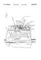
- FIG. 1is a front perspective view of a pumping apparatus constructed in accordance with the present invention, and illustrates an interlock, latching and retaining mechanism attached to an infusion system adapted to receive a pumping segment;
- FIG. 2is a front perspective view illustrating the interlock, latching and retaining mechanism of FIG. 1 in a closed configuration and detached from the infusion system;
- FIG. 3is a perspective view of the rear surface of the apparatus shown in FIG. 2;
- FIG. 4is an exploded, perspective view of the interlock, latching and retaining mechanism shown in FIG. 2;
- FIG. 5is a perspective view of the faceplate included in FIG. 4, showing the rear structure of the faceplate;
- FIG. 6is a perspective view of the pumping segment shown in FIG. 1 that is releasably retained by the interlock, latching and retaining mechanism of FIG. 3;
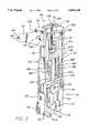
- FIG. 7is a cross-sectional view of the pumping segment of FIG. 5, taken along the line 7--7 in FIG. 5;
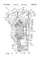
- FIG. 8is an exploded perspective view of components of the infusion system which are attached to the interlock, latching and retaining mechanism;
- FIG. 9is an enlarged perspective view of one of the components shown in FIG. 8;
- FIG. 10is a perspective view of the interlock, latching and retaining mechanism of FIG. 3 in a closed configuration and incorporating the components of FIG. 8;
- FIG. 11is a perspective view of the interlock, latching and retaining mechanism of FIG. 10 in an open configuration and the pumping segment of FIG. 6;
- FIG. 12is a partial, cross-sectional side view of the interlock, latching and retaining mechanism of FIG. 11, shown without the pumping segment.
- the inventionis embodied in an interlock, latching and retaining mechanism which functions to correctly load a unique pumping segment for fluid flow into an infusion system as well as load pumping, flow control and fluid line monitoring structure of the infusion system into appropriate operating positions.
- FIG. 1there is shown an interlock, latching and retaining mechanism 10 constructed in accordance with the present invention.
- the interlock, latching and retaining mechanism 10is incorporated into an infusion system 12 and is adapted to receive an associated pumping segment 14.
- the pumping segment 14is configured for fluid flow and connects a reservoir (not shown) containing infusate to a patient.
- the pumping segment 14includes flow control structure 16 that must be placed in a "flow stop" position prior to placing the segment 14 into the infusion system 12.
- the infusion system 12controls the delivery of the infusate to the patient and includes a pumping structure 18, a flow control structure 20, an air-in-line sensing structure 22 and a pressure sensing structure 24, each of which cooperate with associated structure of the pumping segment 14.
- the interlock, latching and retaining mechanism 10in turn, cooperates with the pumping structure 18 and the air-in-line sensing structure 22 of the infusion system 12, as well as receives the pressure sensing structure 24 of the infusion system 12, each of which are placed into operating position before pumping of fluid through the pumping segment 14 (that has been received by the interlock, latching and retaining mechanism 10) is attempted.
- the interlock, latching and retaining mechanism 10cooperates with the flow control structure 20 of the infusion system 12 to thereby cause the flow control structure 16 of the pumping segment 14 to be placed in a position to allow fluid flow. It is to be noted that the flow control structure 16 of the pumping segment 14 is placed in a position for allowing flow subsequent to placing pumping structures 18 of the infusion system 12 into operating position. This avoids free flow conditions.
- the interlock, latching and retaining mechanism 10includes a shaft 26, a latch arm 28, a rectangular faceplate 30 and a clamp 32.
- the shaft 26 and latch arm 28are each rotatably mounted to the faceplate 30 and are mechanically linked to each other so that by manipulating the latch arm 28, the shaft 26 rotates.
- the clamp 32is pivotably mounted to the faceplate 30 and configured to cooperate with the shaft 26 so that, upon rotation of the shaft 26 the clamp 32 is allowed to open and close so as to releasably engage the pumping segment 14.
- the faceplate 30includes structure for attaching the interlock, latching and retaining mechanism 10 to the infusion system 12 so that the pumping 18, air-in-line 22, flow control 20 and pressure sensing 24 structure of the infusion system 12 may be placed in proper engagement with the interlock, latching and retaining mechanism 10.
- the faceplate 16is generally rectangular in shape and has two long sides 34, two short sides 36 and a perimeter 38.
- the faceplate 30includes two spaced apart arms 40 extending substantially perpendicularly from a rear surface 42 near a top 44 of the faceplate 30. Further, the arms 40 are spaced apart so that they each individually extend from the rear surface 42 near the portion of the perimeter 38 defining the long sides 34 of the faceplate 30.
- Each arm 40includes a through hole 46 near their terminal ends 48 which is adapted to receive associated structure of the infusion system 12.
- An axis 50 extending through the through holes 46is parallel to the faceplate 30 and perpendicular to a long axis 52 of the faceplate 30.
- bosses 54projecting laterally outward from the arms 40 and perpendicularly to the long axis 52 of the faceplate 30 are bosses 54. There is one boss 54 to each arm 40 and each are similarly positioned upon the arms 40. That is, each boss 54 is positioned near the connection of the arm 40 to the faceplate 30.
- a hollow semicircular projection 56Extending laterally across the rear surface 42 near the top 44 of the faceplate 30 and between the spaced apart arms 40 is a hollow semicircular projection 56.
- a lateral rectangular latch aperture 58 formed in a front side 60 of the faceplate 30defines an opening to the hollow semicircular projection 56.
- This hollow semicircular projection 56provides the latch arm 38 with a cavity for rotation,
- latch rod holes 66Formed in upper and lower walls 62 and 64 of the semicircular projection 56 are latch rod holes 66 (FIG. 4 only shows the latch rod hole formed in the upper wall 62).
- An axis 68 extending through the latch rod holes 66is parallel to the long axis 52 of the faceplate 30. It is to be noted that the latch rod holes 66 are adapted to receive a latch rod 70 (also shown in FIG. 4), upon which the latch arm 28 rotates.
- a receiving member 74 for the shaft 26Formed in the shaft receiving member 74 is a through hole 76 that has an axis 78 extending therethrough that is parallel to the long axis 52 of the faceplate 30.
- Projecting from a midsection 80 of the rear surface 42 and along the long axis of the faceplate 30are three spaced apart members 82, 84, 86 for supporting the shaft 26 when it is affixed to the faceplate 30.
- the midsection member 82 positioned closest to the top 44 of the faceplate 30includes a notch 88 formed therein for receiving and engaging the shaft 26.
- the midsection member 84 positioned closest to the bottom 72 of the faceplate 30 and the midsection member 86 formed between the other midsection members 82, 84include a notch 88 for engaging and supporting the shaft 26.
- first 94 and second 96 pairs of clamp supporting membersare also projecting perpendicularly from the rear surface 42 of the faceplate 30, projecting perpendicularly from the rear surface 42 of the faceplate 30,.
- the pairs of supporting members 94, 96form a rectangular pattern on the rear surface 42 of the faceplate 30, wherein the pairs 94, 96 of supporting members form the corners of the rectangular pattern.
- the individual members of the first pair 94are spaced longitudinally apart.
- the individual members of the second pair 96are spaced longitudinally apart.
- the first and second pairs 94, 96are spaced equal lateral distances from the center or long axis 52 of the faceplate 30.
- Formed in each pair of the supporting members 94, 96are through holes 98 adapted to receive structure of a clamp 32.
- an axis 100 extending through the holes 98 formed in the first pair of supporting members 94 and an axis 102 extending through the holes 98 formed in the second pair of supporting members 96are each parallel to the long axis of the faceplate 30.
- the faceplate 30also includes various apertures formed therein (see FIG. 4).
- the rectangular latch aperture 58which is positioned near the top 44 of the faceplate 30 has already been described.
- a circular fluid regulation aperture 104centered in the width of the faceplate 30 is positioned just below the rectangular latch aperture 58.
- Centered in the face plate 30 below the circular fluid regulation aperture 104 and extending longitudinally along the long axis 52 of the faceplate 30is a rectangular pump finger aperture 106.
- On either side of the pump follower aperture 106are a pair of longitudinally extending rectangular clamping finger apertures 108.
- a square pressure sensor aperture 110Directly below the pumping follower aperture 106 and also centered in the width of the faceplate 30 is a square pressure sensor aperture 110.
- a longitudinally elongate and irregularly-shaped aperture 112is formed in the faceplate 30 substantially along the long axis 52 of the faceplate 30.
- Formed within the irregularly shaped aperture 112is a vertical backwall 114 and a horizontal bottom wall 116.
- the vertical backwall 114is attached at its upper end 118 to a bottomside of the midsection member 84 positioned closest to the bottom 72 of the faceplate 30 and at its bottom end 120 to the horizontal bottom wall 116.
- formed in the vertical backwall 114is an oval-shaped hole 122.
- a circular air sensing aperture 124Located at approximately the same longitudinal location along the faceplate 30 and next to the irregularly shaped aperture 112 is a circular air sensing aperture 124. Extending from the circular air sensing aperture 124 and projecting perpendicularly from the rear surface 42 of the faceplate 30 is a cylindrical sidewall 126.
- the shaft 26is cylindrical in shape and has various gearing and camming surfaces affixed to its exterior 128.
- a top end 130 of the shaft 26is a conventional straight tooth gear 132.
- a bevel gear 134is attached to the shaft 26 immediately adjacent to and just below the straight tooth gear 132.
- the bevel gear 134has teeth 136 about approximately 50% of its circumference. The rest of the circumference is without teeth 136.
- the bevel gear 134is configured upon the shaft 26 with its smallest diameter positioned closest to the top end 118 of the shaft 26.
- Located near a bottom end 137 of the shaft 26is a third gear 138.
- the third gear 138is a crossed helical gear and has curved and inclined teeth 112.
- a first cam 142is positioned proximal to and below the bevel gear 134.
- a second cam 144is below and spaced apart from the first cam 144.
- a third cam 146is proximate and below the second cam 144.
- the latch arm 28is generally shaped like a "g” with an additional latch projection 150 extending away from the "head” and approximately at a right angle to the "tail” of the g-shaped latch arm.
- the latch projectionincludes a downwardly extending extension 151 which is directed substantially perpendicularly to upper and lower surfaces 152, 154 of the latch arm 28.
- a hole 156is formed in the "head” of the g-shaped latch arm 28 and is adapted to fixedly receive the latch rod 70.
- the latch rod 70is cylindrical in shape and has a top end 158 and a bottom end 160.
- the latch rod 70is configured to be received in the shaft holes 66 formed in the upper and lower walls 62, 64 of the latch aperture 56.
- the top end of 158 of the latch rod 70may be threaded or otherwise conventionally configured for fastening it to the faceplate 30.
- a midsection 162is adapted to fixably retain the latch arm 28.
- the bottom end 160 of the latch rod 70is adapted to be attached to an approximately a one quarter portion of a gear ring 166.
- the gear ring 166includes a receiving hole 164 into which the latch rod 70 is placed with an interference fit.
- About an outer circumference 168 of the gear ring 166is formed a wall 170 which extends substantially perpendicularly to the outer circumference 168.
- the clamp 32includes two opposing members 172, each of which are substantially identical in shape.
- Each opposing member 72includes a first portion 174 lying substantially perpendicular to a second portion 176.
- the first portion 174includes inside and outside surfaces 178, 180 and terminal end 186 that is perpendicular to the upper and lower perimeters 182, 184.
- Extending from the terminal end 186 and parallel to the upper and lower perimeters 182, 184 of the first portion 174are three spaced apart clamping fingers 188.
- Extending perpendicularly outward from each of the upper and lower perimeters 182, 184is a peg 190 about which the members 172 pivot.
- the second portion 176 of the opposing members 172includes two parallel spaced apart arms 192 each extending substantially perpendicularly from the first portion 174.
- the spaced apart arms 192are adapted to engage and cooperate with the first and second cams 142, 144 respectively.
- FIGS. 2 and 3wherein the components of the interlock, latching and retaining mechanism 10 are shown in their assembled form.
- an assembled interlock, latching and retaining mechanism 10to mount the latch arm 28 to the latch rod 70 the bottom end 160 of the latch rod 70 is inserted through the latch rod hole 66 formed in the upper wall 62 of the semicircular projection 56.
- the head of the g-shaped latch arm 28is then placed within the semicircular projection 56 with its downwardly pointing extension 151 directed towards the bottom 72 of the faceplate 30 and the bottom end 160 of the latch rod 70 is inserted through the hole 156 formed in the latch arm 28.
- the bottom end 160is inserted through the latch rod hole 66 formed in the lower wall 64 of the semicircular projection 56. Thereafter, the bottom end 160 of the latch rod 70 is then fixedly placed into the receiving hole 164 of the gear ring 166. Finally, using conventional means, the latch rod 70 is rotatably mounted within the latch rod hole 66 formed in the upper wall 62.
- the latch arm 28is attached to the latch rod 70 so that the latch arm 28 of the assembled interlock, latching and retaining mechanism 10 is positioned in its fully closed position when a terminal end of the wall 170 formed on the outer circumference 168 of the gear ring 166 engages the rear surface 42 of a right side 196 of the front 60 of the faceplate 30. That is, the latch arm 28 and latch rod 70 are properly oriented where the latch arm 28 is completely swung to a left side 198 of the faceplate 30 when the gear ring 166 is completely swung to the right side 196.
- the clamp 32is attached to the faceplate 30 so that each of the terminal ends 186 of the pair of opposing members 172 of the clamp 32 project through one of the pair of pump finger apertures 108 respectively and so that each of the spaced apart arms 192 point toward the faceplate long axis 52 or towards that center of the faceplate 30.
- the pegs 188 formed on each of the opposing numbers 172 of the clamp 32are placed into the through holes 98 formed in the supporting members 94, 96 extending from the rear surface 42 of the faceplate 30.
- the shaft 26is rotatably mounted to the rear surface 42 of the faceplate 30 by inserting the bottom end 137 of the shaft 26 into the through hole 76 formed in the receiving member 74 extending from the bottom 72 of the rear surface 42 of the faceplate 30.
- the shaft 26is mounted to the rear surface 42 of the faceplate 30 so that it cooperates with the clamp 32, the rear surface 42 of the faceplate 30 and the gear ring 166 attached to the latch rod 70.
- the straight tooth gear 132 affixed to the top end 130 of the shaft 26is placed within the gear ring 166 so that the portion of the bevel gear 134 that lacks teeth 136 faces away from the rear surface 42 of the faceplate 30.
- the raised portions 200 of the first, second and third cams 142, 144, 146point away from the rear surface 42 of the faceplate 30.
- the shaft 26engages mid-section members 182, 184, 186 extending from the rear surface 42 of the faceplate 30.
- the pumping segment 14may be releasably retained by the interlock, latching and retaining mechanism 10. That is, the clamp 32 operates to retain the pumping segment 14 against the faceplates 30 when the latch arm 28 is closed, but is releasably retained in that as the latch arm 28 is rotated to its open position, the shaft 26 cooperates with the clamp 32 to allow it to pivot and thereby release the pumping segment 14. Further, the pumping segment 14 is to cooperate with an infusion system 12 which functions to control the transfer of fluid from a reservoir to a delivery site. The infusion system 12 delivers fluid from the reservoir to a proximal end 202 (see FIG. 6) of the pumping segment 14 by way of conventional tubing.
- the fluidpasses through the pumping segment 14 and exits a distal end 204 (see FIG. 6) of the pumping segment 14.
- Attached to the distal end 204may be additional conventional tubing of the infusion system that transports the fluid away from the pumping segment 14 and towards a delivery site.
- the engineered pumping segment 14is generally elongate in shape. Extending from the proximal end 202 of the elongate pumping segment 14 is a cylindrical tubing fitting 206 that is adapted to attach to conventional tubing (not shown) of the infusion system and that defines an entrance for the passage of fluid into the pumping segment 14. Similarly, extending from the distal end 204 is another cylindrical tubing fitting 208 that also is adapted to attach to conventional tubing of a pumping system and that defines an exit port for fluid passing through the pumping segment 14. The pumping segment 14 also includes a flange 210 extending substantially perpendicularly from the top of a sidewall 214 of the pumping segment 14.
- the flange 210is formed about the distal end 204 and on either side of the midsection of the pumping segment 14 and terminates at parallel longitudinal locations on either side of the pumping segment 14.
- the engineered pumping segment 14also includes a slider 216.
- the slider 216is adapted to fit around and travel longitudinally along a portion of the pumping segment 14 near its proximal end 202.
- the slider 216has a first long side 218 and a second long side 219 and a pair of short sides 220 completing its generally rectangular cross-sectional shape.
- Formed in substantially the center of the first long side 218is a groove 220.
- Formed within the groove 220,is a socket 222 which is adapted to receive and retain a ball bearing 226.
- formed into the short sides 220 and extending the length of the slider 216 and substantially perpendicularly therefrom,are rounded low-profile projections or ears 228.
- the engineered pumping segment 14includes an elastomeric membrane 230 that is sandwiched between a base 232 and a cover 234.
- the path that fluid takes through the pumping segment 14is defined by the membrane 230 and base 232.
- the cover 234generally functions to sealingly retain the membrane 230 against the base 232 as well as against itself.
- the pumping segment 14In cooperation with the interlock, latching and retaining mechanism 10 and the infusion system 12, the pumping segment 14 performs three different functions. Referring again to FIG. 6, near the proximal end 202 of the engineered pumping segment 14 there is structure functioning to regulate flow rates through the pumping segment 14 In an intermediate section 236 of the pumping segment 14 there is structure adapted to cooperate with the infusion system 12 to peristaltically pump fluids through the pumping segment 14 Near its distal end 204, the pumping segment 14 has structure adapted to cooperate with the infusion system 12 to sense the pressure of fluid passing through the pumping segment 14.
- Fluid flow regulationis generally accomplished in the pumping segment 14 through the use of the slider 216 which cooperates with associated structure of the infusion system.
- the cover 234Near the proximal end 202 of the pumping segment 14 the cover 234 provides access to the elastomeric membrane 230.
- the ballbearing 226functions to depress the membrane 234 into the fluid flow path, whereby the cross-sectional area through which fluid may flow is altered.
- the slider 216travels along the base 232 it depresses the membrane 230 into the flow path to varying degrees. By altering the fluid flow path and by doing so to varying degrees, the slider 216 regulates the flow of fluid through the pumping segment 14.
- peristaltic pumpingis facilitated primarily through the cooperation of the membrane 230 and cover 234 of the pumping segment 14.
- the cover 234provides further access to the membrane 230, through which a peristaltic pumping mechanism (not shown) of the infusion system 12 operates.
- the peristaltic pumping mechanismoperates to sequentially depress adjacent portions of the membrane 230 into the fluid flow path to thereby advance fluid through the pumping segment 14.
- Pressure sensing of fluids flowing through the pumping segment 14is facilitated primarily through the cooperation of the membrane 230 and cover 234 of the pumping segment 14. Near the distal end 204 of the pumping segment 14, the cover 234 again provides access to the membrane 230.
- the membrane 230is formed into a generally hollow and flexible dome-shaped pressure vessel 238 with a cylindrical sidewall 240 which acts as a pressure diaphragm for transferring pressure information regarding fluid flowing through the pumping segment 14.
- the infusion system 12includes a frame 242 to which the interlock, latching and retaining mechanism 10 is attached.
- the frame 242includes a first vertical portion 244 and a second vertical portion 246 which are connected at their bottoms 248, 250 (respectively) by a horizontal portion 252.
- the first vertical portion 246is adapted to be mounted proximal to the rear surface 42 of the faceplate 30.
- the second vertical portion 246is adapted to be mounted to the arms 40 extending from the rear surface 42 of the faceplate 30.
- the second vertical portion 246is also adapted to include structure to which a photo-detector 254 is mounted.
- the photo-detector 254is configured to transmit light energy between two spaced apart members 256 embodying the detector 254 and to receive the wall 170 extending from the outer circumference 168 of the gear ring 166.
- the horizontal portion 252includes an upwardly extending vertical frame 258.
- the vertical frame 258is adapted to retain a peristaltic pumping mechanism 260.
- the peristaltic pumping mechanism 260includes a motor 262 that extends below the horizontal portion 252.
- Extending upwardly and within the vertical frame 258is a motor shaft 264 that is driven by the motor 262 and that cooperates with a plurality of fingers 266.
- the fingers 266are mounted side by side within the vertical frame 258 substantially perpendicularly to the motor shaft 264 and are slidably retained by their first end 268 within the vertical frame 258.
- a second end 270 of the fingers 266is adapted to project through the finger aperture 108 formed in the faceplate 30. It is to be noted that as the motor shaft 264 is caused to rotate, the fingers 266 alternatively rise and fall in a perpendicular motion to the motor shaft 264.
- the interlock, latching and retaining mechanism 10also interacts with a flow control actuator 272 (see FIG. 8) of the infusion system 12 that is adapted to be retained by the faceplate 30.
- the flow control actuator 272has a front surface 274 that has a circular perimeter 276. Extending from the front surface 274 is a cylindrical projection 278 and an irregularly shaped projection 279.
- a back surface 280 of the flow control actuator 272includes a bevel gear 282 over 80% of the circumference projecting away from and perpendicularly to the front surface 274.
- the interlock, latching and retaining mechanism 10receives a pressure sensor 284 of the infusion system 12 (see FIG. 8).
- the pressure sensor 284is adapted to be retained within the square pressure aperture 110 and to sense pressure existing within the pumping segment 14.
- the interlock, latching and retaining mechanism 10receives a curtain 286 that is adapted to assure that the slider 216 is placed in its flow stop position prior to the placement of the pumping segment 14 within the clamp 32.
- the curtain 286includes a horizontal portion 288 connecting two spaced apart downwardly directed portions 290. Formed into the downwardly directed portions 290 are cut-outs 292 which receive the ears 228 formed into the slider 216. Extending from a rear side 294 of the curtain 286 are projections 296 which aid in attaching the curtain 286 to the faceplate 30.
- the air-in-line sensor 298includes a first housing 300 which cooperates with a spring 302 and a second housing 304.
- the second housing 304includes an elongate portion 306 having first 308 and second 310 ends. Attached to the first end 308 is a sideways extending projection 312 the underside 314 of which is adapted to engage conventional tubing.
- the second end 310includes a helical gear 316 comprising a segment of a circle and having curved and inclined teeth 318.
- the first housing 300includes a front surface 320 for engaging conventional tubing and a back surface 322 that is adapted to receive forces applied by the spring 302.
- Contained within each of the first and second housings 300, 304are transducers (not shown), one for transmitting ultrasonic energy and the other for receiving ultrasonic energy.
- FIG. 9there is shown an enlarged view of the helical gear 316 detached from the second housing 304.
- the helical gear 316has curved and inclined teeth 318. It is to be noted that the helical gear 316 cooperates with the third gear 138 attached to the bottom end 137 of the shaft 26 so that upon rotation of the shaft 26 the second housing 304 rotates to thereby place the sideways extending projection 312 into and out of operating position.
- the interlocking, latching and retaining mechanism 10may be attached to the frame 242 and may incorporate the previously described components of the infusion system 12.
- the through holes 46 formed near the terminal ends 48 of the pair of arms 40 extending from the rear surface 42 of the faceplate 30each receive a laterally extending projection 324 formed on the first vertical portion 244 of the infusion system frame 242.
- the bosses 54 extending from each arm 40are received in holes 326 formed in the second vertical portion 246 of the frame 242.
- the fingers 266 of the peristaltic pumping mechanism 260 mounted to the frame 242extend through the pump fingers aperture 108.
- the pump fingers 266provide direct visual display of the pumping operating of the pumping mechanism 260.
- the pumping segment 14be comprised of clear material so that the pumping operation of the pumping mechanism 260 can be observed when the pumping segment 14 is placed in the interlock, latching and retaining mechanism 10.
- the sliding flow control actuator 272is to be inserted into the circular fluid regulation aperture 104 formed into the faceplate 30.
- the flow control actuator 272is oriented so that the projections 278 extending therefrom project through the front side 60 of the faceplate 30 and so that the projections 278 are substantially vertically aligned when the latch arm 28 is in its closed position.
- the bevel gear 282 (not shown) of the flow control actuator 272is oriented so that its teeth are interspaced between the teeth of the bevel gear 138 (not shown) affixed to the shaft 26.
- the curtain 286is received in the faceplates 30 just below the latch arm 28 with its downwardly directed portions 290 substantially straddling the flow control actuator 272.
- the projections 296 extending from the rear side 294 (not shown) of the curtain 286snap into associated receptacles (not shown) of the faceplate 30.
- the first housing 300 of the air-in-line sensor 298is fixedly placed within the irregularly shaped aperture 112.
- the spring 302(not shown)is first placed within the irregularly shaped aperture 112 and is placed between the vertical backwall 114 (not shown) of the irregularly shaped aperture 112 and a back surface 322 (not shown) of the first housing 300.
- the front surface 320 of the first housing 300is accessible through the irregularly shaped aperture 112.
- the second housing 304is placed within the circular air sensing aperture 124.
- the raised portions 200 of the first and second cams 142, 144lose contact with the second portion 176 of the clamp 32.
- the opposing members 172 of the clamp 32are permitted to pivot about their pegs 190.
- the shaft 26cooperates with the flow control actuator 272 to orient the projections 278, 279 extending therefrom so that they may be received by the groove 222 formed in the slider 216 of the pumping segment 14.
- the irregularly shaped projection 279is adapted to prohibit improper placement of the pumping segment 14 into the clamp 32. Should the pumping segment 14 be placed in the clamp 32 with only a portion of its flange 210 received in the clamping fingers 188 and with the projections 278, 279 not received by the groove 222, upon placing the interlock, latching and retaining mechanism 10 in its closed configuration, the slider 216 will not be moved from its "flow stop" position.
- the intermediate section 236 of the pumping segment 14, where the cover 234 provides access to the membrane 230is placed in alignment with the pump fingers aperture 106.
- the dome shaped pressure vessel 238 of the pumping segment 14is placed in alignment with the pressure sensor 284.
- the conventional tubing 334which is attached to the cylindrical tubing fitting 208 formed on the distal end 204 of the pumping segment 14 is placed adjacent the front surface 320 of the first housing 300.
- the latch arm 28can be rotated to its closed position.
- the latch arm 28is rotated to its closed position, the previously described interactions between the interlock, latching and retaining mechanism 10 and the other components of the infusion system 12 occur in reverse.
- the latch arm 28is rotated to its closed position (not shown)
- the frame 242moves back towards the faceplate 30 and, by way of its engagement with the first and second cams 142, 146 of the shaft 26, the clamp 32 is prevented from pivoting and thereby securely holds the pumping segment 14 in place.
- the flow control actuator 272is rotated, thereby moving the slider 216 to the proximal end 202 of the pumping segment 14, a position where maximum flow through the pumping segment 14 is permitted. As the slider 216 so moves, the ears 228 slide behind the downwardly directed portions 290 of the curtain 286. Finally, when the latch arm 28 is closed, a proper interface between the domed-shaped pressure vessel 238 and the pressure sensor 284 is created and the wall 170 extending from the outer circumference 168 of the gear ring 166 travels within the photodetector 254, thereby interrupting the light energy transmitted by the detector 254 and indicating to the infusion system 12 that the latch arm 28 is closed.
- the interlock, latching and retaining mechanism 10functions to place at least one finger 266 of the peristaltic pumping mechanism 260 in a position to occlude fluid flow prior to causing the slider 216 of the pumping segment 14 to move to a position for allowing fluid flow. In this way, undesired free flow conditions are avoided.
- interlock, latching and retaining mechanism 10operates to ensure proper sequencing of operation by placing fluid line monitoring structure 22, i.e., air-in-line sensing, as well as the pumping structure 18 of the infusion system 12 into operating position contemporaneously with the clamp 32 securely holding the pumping segment 14 and the gear ring 266 causing the photodetector 254 to communicate to the infusion system 12 that the latch arm 28 is being closed.
- fluid line monitoring structure 22i.e., air-in-line sensing
- the pumping structure 18 of the infusion system 12into operating position contemporaneously with the clamp 32 securely holding the pumping segment 14 and the gear ring 266 causing the photodetector 254 to communicate to the infusion system 12 that the latch arm 28 is being closed.
- the interlock, latching and retaining mechanismmay be appropriately configured to cooperate with other pumping segment designs and may be adapted to cooperate with a wide range of segments for fluid flow. Additionally, the present invention is contemplated to be incorporated into an infusion system lacking one or more of pumping, flow control and fluid monitoring structures.
- the interlock, latching and retaining mechanism 10functions, through the manipulation of the single latch arm 26, to quickly, reliably and simply load the pumping segment 14 for fluid flow into the infusion system 12 as well as load pumping 18, flow control 16 and fluid line monitoring structures 22 into engagement with the pumping segment 14.
Landscapes
- Engineering & Computer Science (AREA)
- Health & Medical Sciences (AREA)
- General Engineering & Computer Science (AREA)
- Mechanical Engineering (AREA)
- Biomedical Technology (AREA)
- Heart & Thoracic Surgery (AREA)
- Hematology (AREA)
- Life Sciences & Earth Sciences (AREA)
- Animal Behavior & Ethology (AREA)
- General Health & Medical Sciences (AREA)
- Public Health (AREA)
- Veterinary Medicine (AREA)
- Anesthesiology (AREA)
- Vascular Medicine (AREA)
- Infusion, Injection, And Reservoir Apparatuses (AREA)
- Reciprocating Pumps (AREA)
- Materials For Medical Uses (AREA)
Abstract
Description
Claims (42)
Priority Applications (11)
| Application Number | Priority Date | Filing Date | Title |
|---|---|---|---|
| US08/305,468US5601420A (en) | 1994-09-12 | 1994-09-12 | Interlock, latching, and retaining mechanism for an infusion pump |
| DE69533451TDE69533451T2 (en) | 1994-09-12 | 1995-09-11 | MECHANISM FOR CONNECTING, LOCKING AND HOLDING FOR INFUSION PUMP |
| CA002199629ACA2199629C (en) | 1994-09-12 | 1995-09-11 | Interlock, latching and retaining mechanism for an infusion pump |
| PT95935037TPT839062E (en) | 1994-09-12 | 1995-09-11 | RIGID, IMMOBILIZATION AND RETAINING INTERFACE MECHANISM FOR A INFUSA PUMP |
| ES95935037TES2123472T3 (en) | 1994-09-12 | 1995-09-11 | MECHANISM OF INTERLOCK, HITCH AND RETENTION FOR AN INFUSION PUMP. |
| JP51041896AJP3382622B2 (en) | 1994-09-12 | 1995-09-11 | Interlocking latch holding mechanism for infusion pump |
| EP95935037AEP0839062B1 (en) | 1994-09-12 | 1995-09-11 | Interlock, latching and retaining mechanism for an infusion pump |
| DE0839062TDE839062T1 (en) | 1994-09-12 | 1995-09-11 | MECHANISM TO CONNECT, LOCK AND HOLD FOR AN INFUSION PUMP |
| AT95935037TATE274937T1 (en) | 1994-09-12 | 1995-09-11 | MECHANISM FOR CONNECTING, LOCKING AND HOLDING AN INFUSION PUMP |
| DK95935037TDK0839062T3 (en) | 1994-09-12 | 1995-09-11 | Connection, locking and retaining mechanism for an infusion pump |
| PCT/US1995/012034WO1996008278A2 (en) | 1994-09-12 | 1995-09-11 | Interlock, latching and retaining mechanism for an infusion pump |
Applications Claiming Priority (1)
| Application Number | Priority Date | Filing Date | Title |
|---|---|---|---|
| US08/305,468US5601420A (en) | 1994-09-12 | 1994-09-12 | Interlock, latching, and retaining mechanism for an infusion pump |
Publications (1)
| Publication Number | Publication Date |
|---|---|
| US5601420Atrue US5601420A (en) | 1997-02-11 |
Family
ID=23180929
Family Applications (1)
| Application Number | Title | Priority Date | Filing Date |
|---|---|---|---|
| US08/305,468Expired - LifetimeUS5601420A (en) | 1994-09-12 | 1994-09-12 | Interlock, latching, and retaining mechanism for an infusion pump |
Country Status (10)
| Country | Link |
|---|---|
| US (1) | US5601420A (en) |
| EP (1) | EP0839062B1 (en) |
| JP (1) | JP3382622B2 (en) |
| AT (1) | ATE274937T1 (en) |
| CA (1) | CA2199629C (en) |
| DE (2) | DE839062T1 (en) |
| DK (1) | DK0839062T3 (en) |
| ES (1) | ES2123472T3 (en) |
| PT (1) | PT839062E (en) |
| WO (1) | WO1996008278A2 (en) |
Cited By (94)
| Publication number | Priority date | Publication date | Assignee | Title |
|---|---|---|---|---|
| US5823746A (en)* | 1996-08-14 | 1998-10-20 | Sims Deltec, Inc. | Reusable pressure plates and methods |
| US5842841A (en)* | 1996-04-10 | 1998-12-01 | Baxter International, Inc. | Volumetric infusion pump with transverse tube loader |
| USD427305S (en)* | 1998-03-09 | 2000-06-27 | Cole Mark S | Vertex chamber cassette |
| US6106249A (en)* | 1997-04-18 | 2000-08-22 | Nestec S.A. | Peristaltic pump |
| US6213723B1 (en)* | 1996-06-24 | 2001-04-10 | Baxter International Inc. | Volumetric infusion pump |
| US6231320B1 (en)* | 1998-06-12 | 2001-05-15 | Abbott Laboratories | Drug infusion pumping cassette latching mechanism |
| US20030220609A1 (en)* | 2002-05-24 | 2003-11-27 | Robert Childers | Medical fluid pump |
| US20030220598A1 (en)* | 2002-05-24 | 2003-11-27 | Don Busby | Automated dialysis system |
| US20030217957A1 (en)* | 2002-05-24 | 2003-11-27 | Bowman Joseph H. | Heat seal interface for a disposable medical fluid unit |
| US20030220605A1 (en)* | 2002-05-24 | 2003-11-27 | Bowman Joseph H. | Disposable medical fluid unit having rigid frame |
| US20030220607A1 (en)* | 2002-05-24 | 2003-11-27 | Don Busby | Peritoneal dialysis apparatus |
| US20030217964A1 (en)* | 2002-05-24 | 2003-11-27 | Eu Bruce Ming-Da | Membrane material for automated dialysis system |
| US20030233069A1 (en)* | 2002-06-14 | 2003-12-18 | John Gillespie | Infusion pump |
| USD504507S1 (en)* | 2003-09-19 | 2005-04-26 | Hospira, Inc. | Pump cassette |
| US20050182355A1 (en)* | 2002-01-03 | 2005-08-18 | Tuan Bui | Method and apparatus for providing medical treatment therapy based on calculated demand |
| US20050209563A1 (en)* | 2004-03-19 | 2005-09-22 | Peter Hopping | Cassette-based dialysis medical fluid therapy systems, apparatuses and methods |
| US20050267401A1 (en)* | 2004-05-25 | 2005-12-01 | Sherwood Services, Ag. | Safety interlock system for an enteral feeding pump |
| US20060004327A1 (en)* | 2002-09-26 | 2006-01-05 | Sherwood Services Ag | Safety interlock system for an enteral feeding pump |
| US6985870B2 (en) | 2002-01-11 | 2006-01-10 | Baxter International Inc. | Medication delivery system |
| US6997905B2 (en) | 2002-06-14 | 2006-02-14 | Baxter International Inc. | Dual orientation display for a medical device |
| US20070135758A1 (en)* | 2000-02-10 | 2007-06-14 | Baxter International Inc. | Method and apparatus for monitoring and controlling peritoneal dialysis therapy |
| US7238164B2 (en) | 2002-07-19 | 2007-07-03 | Baxter International Inc. | Systems, methods and apparatuses for pumping cassette-based therapies |
| US20080039824A1 (en)* | 2003-09-22 | 2008-02-14 | Hospira, Inc. | Fluid delivery device identification and loading system |
| US20080154177A1 (en)* | 2006-11-21 | 2008-06-26 | Baxter International Inc. | System and method for remote monitoring and/or management of infusion therapies |
| US20080200869A1 (en)* | 2007-02-15 | 2008-08-21 | Baxter International Inc. | Dialysis system with efficient battery back-up |
| US20080200868A1 (en)* | 2007-02-15 | 2008-08-21 | One Baxter Parkway | Dialysis system having video display with ambient light adjustment |
| US20080200865A1 (en)* | 2007-02-15 | 2008-08-21 | Baxter International Inc. | Dialysis system having optical flowrate detection |
| US20090053085A1 (en)* | 2007-08-24 | 2009-02-26 | Thompson Loren M | Peristalitic pump assembly and method for attaching a cassette thereto |
| US20090087327A1 (en)* | 2007-09-27 | 2009-04-02 | Voltenburg Jr Robert R | Peristaltic pump and removable cassette therefor |
| US20090087326A1 (en)* | 2007-09-27 | 2009-04-02 | Voltenburg Jr Robert R | Peristaltic pump assembly |
| US20090087325A1 (en)* | 2007-09-27 | 2009-04-02 | Voltenburg Jr Robert R | Peristaltic pump assembly and regulator therefor |
| US20100106082A1 (en)* | 2008-10-24 | 2010-04-29 | Baxter International Inc. | In situ tubing measurements for infusion pumps |
| US20100130934A1 (en)* | 2007-03-12 | 2010-05-27 | Jean-Denis Rochat | Pumping unit for enteral or parenteral nutrition or perfusion |
| US7731689B2 (en) | 2007-02-15 | 2010-06-08 | Baxter International Inc. | Dialysis system having inductive heating |
| US20110158823A1 (en)* | 2009-12-31 | 2011-06-30 | Baxter International Inc. | Shuttle pump with controlled geometry |
| US20110313358A1 (en)* | 2009-01-30 | 2011-12-22 | Nestec S.A. | Infusion pump cassette with anti-free-flow valve mechanism |
| US8137083B2 (en) | 2009-03-11 | 2012-03-20 | Baxter International Inc. | Infusion pump actuators, system and method for controlling medical fluid flowrate |
| WO2012088401A1 (en) | 2010-12-22 | 2012-06-28 | Hospira, Inc. | Fluid delivery device identification and loading system |
| US20130071272A1 (en)* | 2011-09-19 | 2013-03-21 | Jeffery T. Juretich | Peristaltic pump cassette and method of installing same |
| US20130142670A1 (en)* | 2006-11-13 | 2013-06-06 | Q-Core Medical Ltd. | Finger-type peristaltic pump comprising a ribbed anvil |
| US8558964B2 (en) | 2007-02-15 | 2013-10-15 | Baxter International Inc. | Dialysis system having display with electromagnetic compliance (“EMC”) seal |
| US8567235B2 (en) | 2010-06-29 | 2013-10-29 | Baxter International Inc. | Tube measurement technique using linear actuator and pressure sensor |
| US20140121601A1 (en)* | 2012-10-30 | 2014-05-01 | John C. Hoenninger, III | Apparatus and method of mitigating free flow in a fluid administration set |
| CN104548268A (en)* | 2014-10-08 | 2015-04-29 | 河南忱诺科技有限公司 | Spherical full-automatic gravitational venous transfusion monitor |
| US9056160B2 (en) | 2006-11-13 | 2015-06-16 | Q-Core Medical Ltd | Magnetically balanced finger-type peristaltic pump |
| US9333290B2 (en) | 2006-11-13 | 2016-05-10 | Q-Core Medical Ltd. | Anti-free flow mechanism |
| US9381288B2 (en) | 2013-03-13 | 2016-07-05 | Thoratec Corporation | Fluid handling system |
| US9404490B2 (en) | 2004-11-24 | 2016-08-02 | Q-Core Medical Ltd. | Finger-type peristaltic pump |
| US9457158B2 (en) | 2010-04-12 | 2016-10-04 | Q-Core Medical Ltd. | Air trap for intravenous pump |
| US9514283B2 (en) | 2008-07-09 | 2016-12-06 | Baxter International Inc. | Dialysis system having inventory management including online dextrose mixing |
| US9582645B2 (en) | 2008-07-09 | 2017-02-28 | Baxter International Inc. | Networked dialysis system |
| US9657902B2 (en) | 2004-11-24 | 2017-05-23 | Q-Core Medical Ltd. | Peristaltic infusion pump with locking mechanism |
| US9674811B2 (en) | 2011-01-16 | 2017-06-06 | Q-Core Medical Ltd. | Methods, apparatus and systems for medical device communication, control and localization |
| US9675745B2 (en) | 2003-11-05 | 2017-06-13 | Baxter International Inc. | Dialysis systems including therapy prescription entries |
| US9713660B2 (en) | 2012-12-21 | 2017-07-25 | Alcon Research, Ltd. | Cassette clamp mechanism |
| US9726167B2 (en) | 2011-06-27 | 2017-08-08 | Q-Core Medical Ltd. | Methods, circuits, devices, apparatuses, encasements and systems for identifying if a medical infusion system is decalibrated |
| US9855110B2 (en) | 2013-02-05 | 2018-01-02 | Q-Core Medical Ltd. | Methods, apparatus and systems for operating a medical device including an accelerometer |
| US9995611B2 (en) | 2012-03-30 | 2018-06-12 | Icu Medical, Inc. | Air detection system and method for detecting air in a pump of an infusion system |
| US10022498B2 (en) | 2011-12-16 | 2018-07-17 | Icu Medical, Inc. | System for monitoring and delivering medication to a patient and method of using the same to minimize the risks associated with automated therapy |
| US10046112B2 (en) | 2013-05-24 | 2018-08-14 | Icu Medical, Inc. | Multi-sensor infusion system for detecting air or an occlusion in the infusion system |
| US10143795B2 (en) | 2014-08-18 | 2018-12-04 | Icu Medical, Inc. | Intravenous pole integrated power, control, and communication system and method for an infusion pump |
| US10166328B2 (en) | 2013-05-29 | 2019-01-01 | Icu Medical, Inc. | Infusion system which utilizes one or more sensors and additional information to make an air determination regarding the infusion system |
| US10342917B2 (en) | 2014-02-28 | 2019-07-09 | Icu Medical, Inc. | Infusion system and method which utilizes dual wavelength optical air-in-line detection |
| US10430761B2 (en) | 2011-08-19 | 2019-10-01 | Icu Medical, Inc. | Systems and methods for a graphical interface including a graphical representation of medical data |
| US10463788B2 (en) | 2012-07-31 | 2019-11-05 | Icu Medical, Inc. | Patient care system for critical medications |
| US10578098B2 (en) | 2005-07-13 | 2020-03-03 | Baxter International Inc. | Medical fluid delivery device actuated via motive fluid |
| US10596316B2 (en) | 2013-05-29 | 2020-03-24 | Icu Medical, Inc. | Infusion system and method of use which prevents over-saturation of an analog-to-digital converter |
| US10635784B2 (en) | 2007-12-18 | 2020-04-28 | Icu Medical, Inc. | User interface improvements for medical devices |
| US10656894B2 (en) | 2017-12-27 | 2020-05-19 | Icu Medical, Inc. | Synchronized display of screen content on networked devices |
| US10850024B2 (en) | 2015-03-02 | 2020-12-01 | Icu Medical, Inc. | Infusion system, device, and method having advanced infusion features |
| US10918787B2 (en) | 2015-05-26 | 2021-02-16 | Icu Medical, Inc. | Disposable infusion fluid delivery device for programmable large volume drug delivery |
| US11135360B1 (en) | 2020-12-07 | 2021-10-05 | Icu Medical, Inc. | Concurrent infusion with common line auto flush |
| US11167081B2 (en) | 2016-06-16 | 2021-11-09 | Smiths Medical Asd, Inc. | Assemblies and methods for infusion pump system administration sets |
| US11179516B2 (en) | 2017-06-22 | 2021-11-23 | Baxter International Inc. | Systems and methods for incorporating patient pressure into medical fluid delivery |
| USD939079S1 (en) | 2019-08-22 | 2021-12-21 | Icu Medical, Inc. | Infusion pump |
| US11213619B2 (en) | 2013-11-11 | 2022-01-04 | Icu Medical, Inc. | Thermal management system and method for medical devices |
| US11246985B2 (en) | 2016-05-13 | 2022-02-15 | Icu Medical, Inc. | Infusion pump system and method with common line auto flush |
| US11278671B2 (en) | 2019-12-04 | 2022-03-22 | Icu Medical, Inc. | Infusion pump with safety sequence keypad |
| WO2022076337A1 (en) | 2020-10-09 | 2022-04-14 | Becton, Dickinson And Company | Delivery device with cam driven peristaltic pump |
| US11324888B2 (en) | 2016-06-10 | 2022-05-10 | Icu Medical, Inc. | Acoustic flow sensor for continuous medication flow measurements and feedback control of infusion |
| US11344668B2 (en) | 2014-12-19 | 2022-05-31 | Icu Medical, Inc. | Infusion system with concurrent TPN/insulin infusion |
| US11344673B2 (en) | 2014-05-29 | 2022-05-31 | Icu Medical, Inc. | Infusion system and pump with configurable closed loop delivery rate catch-up |
| US11478578B2 (en) | 2012-06-08 | 2022-10-25 | Fresenius Medical Care Holdings, Inc. | Medical fluid cassettes and related systems and methods |
| USD975835S1 (en) | 2017-07-26 | 2023-01-17 | Smiths Medical Asd, Inc. | Infusion set |
| US11679189B2 (en) | 2019-11-18 | 2023-06-20 | Eitan Medical Ltd. | Fast test for medical pump |
| US11801342B2 (en) | 2017-07-19 | 2023-10-31 | Smiths Medical Asd, Inc. | Housing arrangements for infusion pumps |
| US11850414B2 (en) | 2013-03-13 | 2023-12-26 | Tc1 Llc | Fluid handling system |
| US11883361B2 (en) | 2020-07-21 | 2024-01-30 | Icu Medical, Inc. | Fluid transfer devices and methods of use |
| USD1052728S1 (en) | 2021-11-12 | 2024-11-26 | Icu Medical, Inc. | Medical fluid infusion pump |
| US12337165B2 (en) | 2012-07-03 | 2025-06-24 | Tc1 Llc | Catheter pump |
| US12350233B2 (en) | 2021-12-10 | 2025-07-08 | Icu Medical, Inc. | Medical fluid compounding systems with coordinated flow control |
| US12350483B2 (en) | 2016-07-21 | 2025-07-08 | Tc1 Llc | Fluid seals for catheter pump motor assembly |
| US12404858B2 (en) | 2006-03-23 | 2025-09-02 | The Penn State Research Foundation | Catheter blood pump heart assist device |
| USD1091564S1 (en) | 2021-10-13 | 2025-09-02 | Icu Medical, Inc. | Display screen or portion thereof with graphical user interface for a medical device |
Families Citing this family (2)
| Publication number | Priority date | Publication date | Assignee | Title |
|---|---|---|---|---|
| GB2338992B (en)* | 1996-04-10 | 2000-09-06 | Baxter Int | Volumetric infusion pump |
| EP2620173A1 (en)* | 2012-01-30 | 2013-07-31 | Heartware BVBA | Intravenous infusion pump system |
Citations (17)
| Publication number | Priority date | Publication date | Assignee | Title |
|---|---|---|---|---|
| US4199307A (en)* | 1977-07-05 | 1980-04-22 | Andros Incorporated | Medical infusion system |
| US4236880A (en)* | 1979-03-09 | 1980-12-02 | Archibald Development Labs, Inc. | Nonpulsating IV pump and disposable pump chamber |
| US4273121A (en)* | 1978-02-17 | 1981-06-16 | Andros Incorporated | Medical infusion system |
| US4276004A (en)* | 1978-06-14 | 1981-06-30 | Messerschmitt-Boelkow-Biochm Gesellschaft Mit Beschrankter Haftung | Infusion pump |
| US4303376A (en)* | 1979-07-09 | 1981-12-01 | Baxter Travenol Laboratories, Inc. | Flow metering cassette and controller |
| US4493706A (en)* | 1982-08-12 | 1985-01-15 | American Hospital Supply Corporation | Linear peristaltic pumping apparatus and disposable casette therefor |
| US4519792A (en)* | 1982-12-06 | 1985-05-28 | Abbott Laboratories | Infusion pump system |
| US4657490A (en)* | 1985-03-27 | 1987-04-14 | Quest Medical, Inc. | Infusion pump with disposable cassette |
| US4696671A (en)* | 1984-02-08 | 1987-09-29 | Omni-Flow, Inc. | Infusion system having plural fluid input ports and at least one patient output port |
| US4735558A (en)* | 1986-04-08 | 1988-04-05 | Staar Surgical Company | Peristaltic pump latching mechanism |
| US4842584A (en)* | 1987-05-01 | 1989-06-27 | Abbott Laboratories | Disposable fluid infusion pumping chamber cassette and drive mechanism thereof |
| US4857048A (en)* | 1987-05-29 | 1989-08-15 | Hewlett-Packard Company | IV pump and disposable flow chamber with flow control |
| US5056992A (en)* | 1987-05-29 | 1991-10-15 | Hewlett-Packard Company | IV pump and disposable flow chamber with flow control |
| US5074756A (en)* | 1988-05-17 | 1991-12-24 | Patient Solutions, Inc. | Infusion device with disposable elements |
| US5290239A (en)* | 1991-09-26 | 1994-03-01 | Baxter International, Inc. | Intravenous tube safety apparatus |
| US5302093A (en)* | 1992-05-01 | 1994-04-12 | Mcgaw, Inc. | Disposable cassette with negative head height fluid supply and method |
| US5322422A (en)* | 1990-03-15 | 1994-06-21 | Abbott Laboratories | Volumetric pump tube reshaper and method |
- 1994
- 1994-09-12USUS08/305,468patent/US5601420A/ennot_activeExpired - Lifetime
- 1995
- 1995-09-11PTPT95935037Tpatent/PT839062E/enunknown
- 1995-09-11WOPCT/US1995/012034patent/WO1996008278A2/enactiveIP Right Grant
- 1995-09-11JPJP51041896Apatent/JP3382622B2/ennot_activeExpired - Fee Related
- 1995-09-11CACA002199629Apatent/CA2199629C/ennot_activeExpired - Fee Related
- 1995-09-11EPEP95935037Apatent/EP0839062B1/ennot_activeExpired - Lifetime
- 1995-09-11ATAT95935037Tpatent/ATE274937T1/enactive
- 1995-09-11DEDE0839062Tpatent/DE839062T1/enactivePending
- 1995-09-11DEDE69533451Tpatent/DE69533451T2/ennot_activeExpired - Lifetime
- 1995-09-11ESES95935037Tpatent/ES2123472T3/ennot_activeExpired - Lifetime
- 1995-09-11DKDK95935037Tpatent/DK0839062T3/enactive
Patent Citations (17)
| Publication number | Priority date | Publication date | Assignee | Title |
|---|---|---|---|---|
| US4199307A (en)* | 1977-07-05 | 1980-04-22 | Andros Incorporated | Medical infusion system |
| US4273121A (en)* | 1978-02-17 | 1981-06-16 | Andros Incorporated | Medical infusion system |
| US4276004A (en)* | 1978-06-14 | 1981-06-30 | Messerschmitt-Boelkow-Biochm Gesellschaft Mit Beschrankter Haftung | Infusion pump |
| US4236880A (en)* | 1979-03-09 | 1980-12-02 | Archibald Development Labs, Inc. | Nonpulsating IV pump and disposable pump chamber |
| US4303376A (en)* | 1979-07-09 | 1981-12-01 | Baxter Travenol Laboratories, Inc. | Flow metering cassette and controller |
| US4493706A (en)* | 1982-08-12 | 1985-01-15 | American Hospital Supply Corporation | Linear peristaltic pumping apparatus and disposable casette therefor |
| US4519792A (en)* | 1982-12-06 | 1985-05-28 | Abbott Laboratories | Infusion pump system |
| US4696671A (en)* | 1984-02-08 | 1987-09-29 | Omni-Flow, Inc. | Infusion system having plural fluid input ports and at least one patient output port |
| US4657490A (en)* | 1985-03-27 | 1987-04-14 | Quest Medical, Inc. | Infusion pump with disposable cassette |
| US4735558A (en)* | 1986-04-08 | 1988-04-05 | Staar Surgical Company | Peristaltic pump latching mechanism |
| US4842584A (en)* | 1987-05-01 | 1989-06-27 | Abbott Laboratories | Disposable fluid infusion pumping chamber cassette and drive mechanism thereof |
| US4857048A (en)* | 1987-05-29 | 1989-08-15 | Hewlett-Packard Company | IV pump and disposable flow chamber with flow control |
| US5056992A (en)* | 1987-05-29 | 1991-10-15 | Hewlett-Packard Company | IV pump and disposable flow chamber with flow control |
| US5074756A (en)* | 1988-05-17 | 1991-12-24 | Patient Solutions, Inc. | Infusion device with disposable elements |
| US5322422A (en)* | 1990-03-15 | 1994-06-21 | Abbott Laboratories | Volumetric pump tube reshaper and method |
| US5290239A (en)* | 1991-09-26 | 1994-03-01 | Baxter International, Inc. | Intravenous tube safety apparatus |
| US5302093A (en)* | 1992-05-01 | 1994-04-12 | Mcgaw, Inc. | Disposable cassette with negative head height fluid supply and method |
Non-Patent Citations (2)
| Title |
|---|
| Brochure The AVI 200 and Micro 210 Infusion Pumps with the Unique AVI Cassette.* |
| Brochure-The AVI 200 and Micro 210 Infusion Pumps with the Unique AVI Cassette. |
Cited By (200)
| Publication number | Priority date | Publication date | Assignee | Title |
|---|---|---|---|---|
| US5842841A (en)* | 1996-04-10 | 1998-12-01 | Baxter International, Inc. | Volumetric infusion pump with transverse tube loader |
| US6195887B1 (en)* | 1996-04-10 | 2001-03-06 | Baxter International Inc | Volumetric infusion pump |
| US6213723B1 (en)* | 1996-06-24 | 2001-04-10 | Baxter International Inc. | Volumetric infusion pump |
| US5823746A (en)* | 1996-08-14 | 1998-10-20 | Sims Deltec, Inc. | Reusable pressure plates and methods |
| US6106249A (en)* | 1997-04-18 | 2000-08-22 | Nestec S.A. | Peristaltic pump |
| USD427305S (en)* | 1998-03-09 | 2000-06-27 | Cole Mark S | Vertex chamber cassette |
| US6231320B1 (en)* | 1998-06-12 | 2001-05-15 | Abbott Laboratories | Drug infusion pumping cassette latching mechanism |
| US8323231B2 (en) | 2000-02-10 | 2012-12-04 | Baxter International, Inc. | Method and apparatus for monitoring and controlling peritoneal dialysis therapy |
| US10322224B2 (en) | 2000-02-10 | 2019-06-18 | Baxter International Inc. | Apparatus and method for monitoring and controlling a peritoneal dialysis therapy |
| US9474842B2 (en) | 2000-02-10 | 2016-10-25 | Baxter International Inc. | Method and apparatus for monitoring and controlling peritoneal dialysis therapy |
| US20070135758A1 (en)* | 2000-02-10 | 2007-06-14 | Baxter International Inc. | Method and apparatus for monitoring and controlling peritoneal dialysis therapy |
| US8545435B2 (en) | 2002-01-03 | 2013-10-01 | Baxter International, Inc. | Method and apparatus for providing medical treatment therapy based on calculated demand |
| US20050182355A1 (en)* | 2002-01-03 | 2005-08-18 | Tuan Bui | Method and apparatus for providing medical treatment therapy based on calculated demand |
| US7668731B2 (en) | 2002-01-11 | 2010-02-23 | Baxter International Inc. | Medication delivery system |
| US6985870B2 (en) | 2002-01-11 | 2006-01-10 | Baxter International Inc. | Medication delivery system |
| US7087036B2 (en) | 2002-05-24 | 2006-08-08 | Baxter International Inc. | Fail safe system for operating medical fluid valves |
| US10751457B2 (en) | 2002-05-24 | 2020-08-25 | Baxter International Inc. | Systems with disposable pumping unit |
| US6764761B2 (en) | 2002-05-24 | 2004-07-20 | Baxter International Inc. | Membrane material for automated dialysis system |
| US6814547B2 (en) | 2002-05-24 | 2004-11-09 | Baxter International Inc. | Medical fluid pump |
| US7789849B2 (en) | 2002-05-24 | 2010-09-07 | Baxter International Inc. | Automated dialysis pumping system using stepper motor |
| US7815595B2 (en) | 2002-05-24 | 2010-10-19 | Baxter International Inc. | Automated dialysis pumping system |
| US6939111B2 (en) | 2002-05-24 | 2005-09-06 | Baxter International Inc. | Method and apparatus for controlling medical fluid pressure |
| US9775939B2 (en) | 2002-05-24 | 2017-10-03 | Baxter International Inc. | Peritoneal dialysis systems and methods having graphical user interface |
| US6953323B2 (en) | 2002-05-24 | 2005-10-11 | Baxter International Inc. | Medical fluid pump |
| US10137235B2 (en) | 2002-05-24 | 2018-11-27 | Baxter International Inc. | Automated peritoneal dialysis system using stepper motor |
| US20110144569A1 (en)* | 2002-05-24 | 2011-06-16 | Baxter International Inc. | Peritoneal dialysis machine touch screen user interface |
| US20030220608A1 (en)* | 2002-05-24 | 2003-11-27 | Bruce Huitt | Method and apparatus for controlling medical fluid pressure |
| US20030220609A1 (en)* | 2002-05-24 | 2003-11-27 | Robert Childers | Medical fluid pump |
| US8403880B2 (en) | 2002-05-24 | 2013-03-26 | Baxter International Inc. | Peritoneal dialysis machine with variable voltage input control scheme |
| US20060113249A1 (en)* | 2002-05-24 | 2006-06-01 | Robert Childers | Medical fluid machine with air purging pump |
| US20100087777A1 (en)* | 2002-05-24 | 2010-04-08 | Baxter International Inc. | Peritoneal dialysis machine with variable voltage input control scheme |
| US20030220598A1 (en)* | 2002-05-24 | 2003-11-27 | Don Busby | Automated dialysis system |
| US7153286B2 (en) | 2002-05-24 | 2006-12-26 | Baxter International Inc. | Automated dialysis system |
| US7175606B2 (en) | 2002-05-24 | 2007-02-13 | Baxter International Inc. | Disposable medical fluid unit having rigid frame |
| US20030217964A1 (en)* | 2002-05-24 | 2003-11-27 | Eu Bruce Ming-Da | Membrane material for automated dialysis system |
| US20070149913A1 (en)* | 2002-05-24 | 2007-06-28 | Don Busby | Automated dialysis pumping system |
| US20040010223A1 (en)* | 2002-05-24 | 2004-01-15 | Don Busby | Fail safe system for operating medical fluid valves |
| US20070213651A1 (en)* | 2002-05-24 | 2007-09-13 | Don Busby | Automated dialysis pumping system using stepper motor |
| US9675744B2 (en) | 2002-05-24 | 2017-06-13 | Baxter International Inc. | Method of operating a disposable pumping unit |
| US8529496B2 (en) | 2002-05-24 | 2013-09-10 | Baxter International Inc. | Peritoneal dialysis machine touch screen user interface |
| US9504778B2 (en) | 2002-05-24 | 2016-11-29 | Baxter International Inc. | Dialysis machine with electrical insulation for variable voltage input |
| US20030220607A1 (en)* | 2002-05-24 | 2003-11-27 | Don Busby | Peritoneal dialysis apparatus |
| US20030220605A1 (en)* | 2002-05-24 | 2003-11-27 | Bowman Joseph H. | Disposable medical fluid unit having rigid frame |
| US20030217962A1 (en)* | 2002-05-24 | 2003-11-27 | Robert Childers | Medical fluid pump |
| US20030217957A1 (en)* | 2002-05-24 | 2003-11-27 | Bowman Joseph H. | Heat seal interface for a disposable medical fluid unit |
| US7500962B2 (en) | 2002-05-24 | 2009-03-10 | Baxter International Inc. | Medical fluid machine with air purging pump |
| US6997905B2 (en) | 2002-06-14 | 2006-02-14 | Baxter International Inc. | Dual orientation display for a medical device |
| US20100256561A1 (en)* | 2002-06-14 | 2010-10-07 | Baxter International Inc. | Infusion pump with battery operation capability |
| US9514518B2 (en) | 2002-06-14 | 2016-12-06 | Baxter International Inc. | Infusion pump including syringe plunger position sensor |
| US20060184123A1 (en)* | 2002-06-14 | 2006-08-17 | Gillespie John Jr | Infusion pump |
| US7608060B2 (en) | 2002-06-14 | 2009-10-27 | Baxter International Inc. | Infusion pump |
| US7018361B2 (en) | 2002-06-14 | 2006-03-28 | Baxter International Inc. | Infusion pump |
| US9937289B2 (en) | 2002-06-14 | 2018-04-10 | Baxter International Inc. | Method of operating an infusion pump with a multiple orientation display |
| US8888738B2 (en) | 2002-06-14 | 2014-11-18 | Baxter International Inc. | Infusion pump with multiple orientation display |
| US8696632B2 (en) | 2002-06-14 | 2014-04-15 | Baxter International Inc. | Infusion pump with battery operation capability |
| US10092690B2 (en) | 2002-06-14 | 2018-10-09 | Baxter International Inc. | Infusion pump including syringe sensing |
| US20030233069A1 (en)* | 2002-06-14 | 2003-12-18 | John Gillespie | Infusion pump |
| US7238164B2 (en) | 2002-07-19 | 2007-07-03 | Baxter International Inc. | Systems, methods and apparatuses for pumping cassette-based therapies |
| US7537579B2 (en) | 2002-09-26 | 2009-05-26 | Covidien Ag | Safety interlock system for an enteral feeding pump |
| US20060004327A1 (en)* | 2002-09-26 | 2006-01-05 | Sherwood Services Ag | Safety interlock system for an enteral feeding pump |
| US7744554B2 (en) | 2002-12-31 | 2010-06-29 | Baxter International Inc. | Cassette alignment and integrity testing for dialysis systems |
| US20080132828A1 (en)* | 2002-12-31 | 2008-06-05 | Baxter International Inc. | Cassette alignment and integrity testing for dialysis systems |
| US20080103429A1 (en)* | 2002-12-31 | 2008-05-01 | Baxter International Inc. | Pumping material for cassette based dialysis and pumping mechanism using same |
| US20110218487A1 (en)* | 2002-12-31 | 2011-09-08 | Baxter International Inc. | Pumping material for cassette based dialysis and pumping mechanism using same |
| US8206338B2 (en) | 2002-12-31 | 2012-06-26 | Baxter International Inc. | Pumping systems for cassette-based dialysis |
| USD504507S1 (en)* | 2003-09-19 | 2005-04-26 | Hospira, Inc. | Pump cassette |
| US8152486B2 (en)* | 2003-09-22 | 2012-04-10 | Hospira, Inc. | Fluid delivery device identification and loading system |
| US20100094224A1 (en)* | 2003-09-22 | 2010-04-15 | Hospira, Inc. | Fluid delivery device identification and loading system |
| US20080039824A1 (en)* | 2003-09-22 | 2008-02-14 | Hospira, Inc. | Fluid delivery device identification and loading system |
| US9675745B2 (en) | 2003-11-05 | 2017-06-13 | Baxter International Inc. | Dialysis systems including therapy prescription entries |
| US20050209563A1 (en)* | 2004-03-19 | 2005-09-22 | Peter Hopping | Cassette-based dialysis medical fluid therapy systems, apparatuses and methods |
| US20050267401A1 (en)* | 2004-05-25 | 2005-12-01 | Sherwood Services, Ag. | Safety interlock system for an enteral feeding pump |
| US10184615B2 (en) | 2004-11-24 | 2019-01-22 | Q-Core Medical Ltd. | Peristaltic infusion pump with locking mechanism |
| US9657902B2 (en) | 2004-11-24 | 2017-05-23 | Q-Core Medical Ltd. | Peristaltic infusion pump with locking mechanism |
| US9404490B2 (en) | 2004-11-24 | 2016-08-02 | Q-Core Medical Ltd. | Finger-type peristaltic pump |
| US11384748B2 (en) | 2005-07-13 | 2022-07-12 | Baxter International Inc. | Blood treatment system having pulsatile blood intake |
| US10590924B2 (en) | 2005-07-13 | 2020-03-17 | Baxter International Inc. | Medical fluid pumping system including pump and machine chassis mounting regime |
| US10670005B2 (en) | 2005-07-13 | 2020-06-02 | Baxter International Inc. | Diaphragm pumps and pumping systems |
| US12392335B2 (en) | 2005-07-13 | 2025-08-19 | Baxter International Inc. | Medical fluid pumping system having backflow prevention |
| US10578098B2 (en) | 2005-07-13 | 2020-03-03 | Baxter International Inc. | Medical fluid delivery device actuated via motive fluid |
| US12404858B2 (en) | 2006-03-23 | 2025-09-02 | The Penn State Research Foundation | Catheter blood pump heart assist device |
| US9333290B2 (en) | 2006-11-13 | 2016-05-10 | Q-Core Medical Ltd. | Anti-free flow mechanism |
| US20130142670A1 (en)* | 2006-11-13 | 2013-06-06 | Q-Core Medical Ltd. | Finger-type peristaltic pump comprising a ribbed anvil |
| US9056160B2 (en) | 2006-11-13 | 2015-06-16 | Q-Core Medical Ltd | Magnetically balanced finger-type peristaltic pump |
| US10113543B2 (en)* | 2006-11-13 | 2018-10-30 | Q-Core Medical Ltd. | Finger type peristaltic pump comprising a ribbed anvil |
| US9581152B2 (en) | 2006-11-13 | 2017-02-28 | Q-Core Medical Ltd. | Magnetically balanced finger-type peristaltic pump |
| US20080154177A1 (en)* | 2006-11-21 | 2008-06-26 | Baxter International Inc. | System and method for remote monitoring and/or management of infusion therapies |
| US8361023B2 (en) | 2007-02-15 | 2013-01-29 | Baxter International Inc. | Dialysis system with efficient battery back-up |
| US9799274B2 (en) | 2007-02-15 | 2017-10-24 | Baxter International Inc. | Method of controlling medical fluid therapy machine brightness |
| US7998115B2 (en) | 2007-02-15 | 2011-08-16 | Baxter International Inc. | Dialysis system having optical flowrate detection |
| US8870812B2 (en) | 2007-02-15 | 2014-10-28 | Baxter International Inc. | Dialysis system having video display with ambient light adjustment |
| US20080200865A1 (en)* | 2007-02-15 | 2008-08-21 | Baxter International Inc. | Dialysis system having optical flowrate detection |
| US8558964B2 (en) | 2007-02-15 | 2013-10-15 | Baxter International Inc. | Dialysis system having display with electromagnetic compliance (“EMC”) seal |
| US7731689B2 (en) | 2007-02-15 | 2010-06-08 | Baxter International Inc. | Dialysis system having inductive heating |
| US20080200869A1 (en)* | 2007-02-15 | 2008-08-21 | Baxter International Inc. | Dialysis system with efficient battery back-up |
| US20080200868A1 (en)* | 2007-02-15 | 2008-08-21 | One Baxter Parkway | Dialysis system having video display with ambient light adjustment |
| US20100130934A1 (en)* | 2007-03-12 | 2010-05-27 | Jean-Denis Rochat | Pumping unit for enteral or parenteral nutrition or perfusion |
| US8328537B2 (en)* | 2007-03-12 | 2012-12-11 | Jean-Denis Rochat | Pumping unit for enteral or parenteral nutrition or perfusion |
| US20090053085A1 (en)* | 2007-08-24 | 2009-02-26 | Thompson Loren M | Peristalitic pump assembly and method for attaching a cassette thereto |
| US20090087325A1 (en)* | 2007-09-27 | 2009-04-02 | Voltenburg Jr Robert R | Peristaltic pump assembly and regulator therefor |
| US8083503B2 (en) | 2007-09-27 | 2011-12-27 | Curlin Medical Inc. | Peristaltic pump assembly and regulator therefor |
| US7934912B2 (en) | 2007-09-27 | 2011-05-03 | Curlin Medical Inc | Peristaltic pump assembly with cassette and mounting pin arrangement |
| US20090087327A1 (en)* | 2007-09-27 | 2009-04-02 | Voltenburg Jr Robert R | Peristaltic pump and removable cassette therefor |
| US20090087326A1 (en)* | 2007-09-27 | 2009-04-02 | Voltenburg Jr Robert R | Peristaltic pump assembly |
| US8062008B2 (en) | 2007-09-27 | 2011-11-22 | Curlin Medical Inc. | Peristaltic pump and removable cassette therefor |
| US10635784B2 (en) | 2007-12-18 | 2020-04-28 | Icu Medical, Inc. | User interface improvements for medical devices |
| US9690905B2 (en) | 2008-07-09 | 2017-06-27 | Baxter International Inc. | Dialysis treatment prescription system and method |
| US9582645B2 (en) | 2008-07-09 | 2017-02-28 | Baxter International Inc. | Networked dialysis system |
| US10561780B2 (en) | 2008-07-09 | 2020-02-18 | Baxter International Inc. | Dialysis system having inventory management including online dextrose mixing |
| US9697334B2 (en) | 2008-07-09 | 2017-07-04 | Baxter International Inc. | Dialysis system having approved therapy prescriptions presented for selection |
| US9514283B2 (en) | 2008-07-09 | 2016-12-06 | Baxter International Inc. | Dialysis system having inventory management including online dextrose mixing |
| US8105269B2 (en) | 2008-10-24 | 2012-01-31 | Baxter International Inc. | In situ tubing measurements for infusion pumps |
| US20100106082A1 (en)* | 2008-10-24 | 2010-04-29 | Baxter International Inc. | In situ tubing measurements for infusion pumps |
| US8496613B2 (en) | 2008-10-24 | 2013-07-30 | Baxter International Inc. | In situ tubing measurements for infusion pumps |
| US20110313358A1 (en)* | 2009-01-30 | 2011-12-22 | Nestec S.A. | Infusion pump cassette with anti-free-flow valve mechanism |
| US9238101B2 (en)* | 2009-01-30 | 2016-01-19 | Nestec S.A. | Infusion pump cassette with anti-free-flow valve mechanism |
| US8137083B2 (en) | 2009-03-11 | 2012-03-20 | Baxter International Inc. | Infusion pump actuators, system and method for controlling medical fluid flowrate |
| US20110158823A1 (en)* | 2009-12-31 | 2011-06-30 | Baxter International Inc. | Shuttle pump with controlled geometry |
| US8382447B2 (en) | 2009-12-31 | 2013-02-26 | Baxter International, Inc. | Shuttle pump with controlled geometry |
| US9457158B2 (en) | 2010-04-12 | 2016-10-04 | Q-Core Medical Ltd. | Air trap for intravenous pump |
| US8567235B2 (en) | 2010-06-29 | 2013-10-29 | Baxter International Inc. | Tube measurement technique using linear actuator and pressure sensor |
| US20120164006A1 (en)* | 2010-12-22 | 2012-06-28 | Hospira, Inc. | Fluid delivery device identification and loading system |
| EP2655885A4 (en)* | 2010-12-22 | 2018-02-07 | ICU Medical, Inc. | Fluid delivery device identification and loading system |
| US8777590B2 (en)* | 2010-12-22 | 2014-07-15 | Hospira, Inc. | Fluid delivery device identification and loading system |
| WO2012088401A1 (en) | 2010-12-22 | 2012-06-28 | Hospira, Inc. | Fluid delivery device identification and loading system |
| US9674811B2 (en) | 2011-01-16 | 2017-06-06 | Q-Core Medical Ltd. | Methods, apparatus and systems for medical device communication, control and localization |
| US9726167B2 (en) | 2011-06-27 | 2017-08-08 | Q-Core Medical Ltd. | Methods, circuits, devices, apparatuses, encasements and systems for identifying if a medical infusion system is decalibrated |
| US11972395B2 (en) | 2011-08-19 | 2024-04-30 | Icu Medical, Inc. | Systems and methods for a graphical interface including a graphical representation of medical data |
| US11004035B2 (en) | 2011-08-19 | 2021-05-11 | Icu Medical, Inc. | Systems and methods for a graphical interface including a graphical representation of medical data |
| US12346879B2 (en) | 2011-08-19 | 2025-07-01 | Icu Medical, Inc. | Systems and methods for a graphical interface including a graphical representation of medical data |
| US10430761B2 (en) | 2011-08-19 | 2019-10-01 | Icu Medical, Inc. | Systems and methods for a graphical interface including a graphical representation of medical data |
| US11599854B2 (en) | 2011-08-19 | 2023-03-07 | Icu Medical, Inc. | Systems and methods for a graphical interface including a graphical representation of medical data |
| US20130071272A1 (en)* | 2011-09-19 | 2013-03-21 | Jeffery T. Juretich | Peristaltic pump cassette and method of installing same |
| US8459968B2 (en)* | 2011-09-19 | 2013-06-11 | Curlin Medical Inc. | Peristaltic pump cassette and method of installing same |
| US10022498B2 (en) | 2011-12-16 | 2018-07-17 | Icu Medical, Inc. | System for monitoring and delivering medication to a patient and method of using the same to minimize the risks associated with automated therapy |
| US11376361B2 (en) | 2011-12-16 | 2022-07-05 | Icu Medical, Inc. | System for monitoring and delivering medication to a patient and method of using the same to minimize the risks associated with automated therapy |
| US10578474B2 (en) | 2012-03-30 | 2020-03-03 | Icu Medical, Inc. | Air detection system and method for detecting air in a pump of an infusion system |
| US11933650B2 (en) | 2012-03-30 | 2024-03-19 | Icu Medical, Inc. | Air detection system and method for detecting air in a pump of an infusion system |
| US9995611B2 (en) | 2012-03-30 | 2018-06-12 | Icu Medical, Inc. | Air detection system and method for detecting air in a pump of an infusion system |
| US11478578B2 (en) | 2012-06-08 | 2022-10-25 | Fresenius Medical Care Holdings, Inc. | Medical fluid cassettes and related systems and methods |
| US12337165B2 (en) | 2012-07-03 | 2025-06-24 | Tc1 Llc | Catheter pump |
| US12280239B2 (en) | 2012-07-31 | 2025-04-22 | Icu Medical, Inc. | Patient care system for critical medications |
| US11623042B2 (en) | 2012-07-31 | 2023-04-11 | Icu Medical, Inc. | Patient care system for critical medications |
| US10463788B2 (en) | 2012-07-31 | 2019-11-05 | Icu Medical, Inc. | Patient care system for critical medications |
| US20140121601A1 (en)* | 2012-10-30 | 2014-05-01 | John C. Hoenninger, III | Apparatus and method of mitigating free flow in a fluid administration set |
| US9468713B2 (en)* | 2012-10-30 | 2016-10-18 | Hospira, Inc. | Apparatus and method of mitigating free flow in a fluid administration set |
| US9713660B2 (en) | 2012-12-21 | 2017-07-25 | Alcon Research, Ltd. | Cassette clamp mechanism |
| US9855110B2 (en) | 2013-02-05 | 2018-01-02 | Q-Core Medical Ltd. | Methods, apparatus and systems for operating a medical device including an accelerometer |
| US10632241B2 (en) | 2013-03-13 | 2020-04-28 | Tc1 Llc | Fluid handling system |
| US9381288B2 (en) | 2013-03-13 | 2016-07-05 | Thoratec Corporation | Fluid handling system |
| US11850414B2 (en) | 2013-03-13 | 2023-12-26 | Tc1 Llc | Fluid handling system |
| US11547845B2 (en) | 2013-03-13 | 2023-01-10 | Tc1 Llc | Fluid handling system |
| US12048831B2 (en) | 2013-05-24 | 2024-07-30 | Icu Medical, Inc. | Multi-sensor infusion system for detecting air or an occlusion in the infusion system |
| US10046112B2 (en) | 2013-05-24 | 2018-08-14 | Icu Medical, Inc. | Multi-sensor infusion system for detecting air or an occlusion in the infusion system |
| US10874793B2 (en) | 2013-05-24 | 2020-12-29 | Icu Medical, Inc. | Multi-sensor infusion system for detecting air or an occlusion in the infusion system |
| US10596316B2 (en) | 2013-05-29 | 2020-03-24 | Icu Medical, Inc. | Infusion system and method of use which prevents over-saturation of an analog-to-digital converter |
| US10166328B2 (en) | 2013-05-29 | 2019-01-01 | Icu Medical, Inc. | Infusion system which utilizes one or more sensors and additional information to make an air determination regarding the infusion system |
| US12059551B2 (en) | 2013-05-29 | 2024-08-13 | Icu Medical, Inc. | Infusion system and method of use which prevents over-saturation of an analog-to-digital converter |
| US11596737B2 (en) | 2013-05-29 | 2023-03-07 | Icu Medical, Inc. | Infusion system and method of use which prevents over-saturation of an analog-to-digital converter |
| US11433177B2 (en) | 2013-05-29 | 2022-09-06 | Icu Medical, Inc. | Infusion system which utilizes one or more sensors and additional information to make an air determination regarding the infusion system |
| US11213619B2 (en) | 2013-11-11 | 2022-01-04 | Icu Medical, Inc. | Thermal management system and method for medical devices |
| US12076525B2 (en) | 2013-11-11 | 2024-09-03 | Icu Medical, Inc. | Thermal management system and method for medical devices |
| US12083310B2 (en) | 2014-02-28 | 2024-09-10 | Icu Medical, Inc. | Infusion system and method which utilizes dual wavelength optical air-in-line detection |
| US10342917B2 (en) | 2014-02-28 | 2019-07-09 | Icu Medical, Inc. | Infusion system and method which utilizes dual wavelength optical air-in-line detection |
| US11344673B2 (en) | 2014-05-29 | 2022-05-31 | Icu Medical, Inc. | Infusion system and pump with configurable closed loop delivery rate catch-up |
| US10143795B2 (en) | 2014-08-18 | 2018-12-04 | Icu Medical, Inc. | Intravenous pole integrated power, control, and communication system and method for an infusion pump |
| CN104548268A (en)* | 2014-10-08 | 2015-04-29 | 河南忱诺科技有限公司 | Spherical full-automatic gravitational venous transfusion monitor |
| US11344668B2 (en) | 2014-12-19 | 2022-05-31 | Icu Medical, Inc. | Infusion system with concurrent TPN/insulin infusion |
| US10850024B2 (en) | 2015-03-02 | 2020-12-01 | Icu Medical, Inc. | Infusion system, device, and method having advanced infusion features |
| US12115337B2 (en) | 2015-03-02 | 2024-10-15 | Icu Medical, Inc. | Infusion system, device, and method having advanced infusion features |
| US11660386B2 (en) | 2015-05-26 | 2023-05-30 | Icu Medical, Inc. | Disposable infusion fluid delivery device for programmable large volume drug delivery |
| US10918787B2 (en) | 2015-05-26 | 2021-02-16 | Icu Medical, Inc. | Disposable infusion fluid delivery device for programmable large volume drug delivery |
| US12156986B2 (en) | 2015-05-26 | 2024-12-03 | Icu Medical, Inc. | Disposable infusion fluid delivery device for programmable large volume drug delivery |
| US12201811B2 (en) | 2016-05-13 | 2025-01-21 | Icu Medical, Inc. | Infusion pump system and method with common line auto flush |
| US11246985B2 (en) | 2016-05-13 | 2022-02-15 | Icu Medical, Inc. | Infusion pump system and method with common line auto flush |
| US12076531B2 (en) | 2016-06-10 | 2024-09-03 | Icu Medical, Inc. | Acoustic flow sensor for continuous medication flow measurements and feedback control of infusion |
| US11324888B2 (en) | 2016-06-10 | 2022-05-10 | Icu Medical, Inc. | Acoustic flow sensor for continuous medication flow measurements and feedback control of infusion |
| US11167081B2 (en) | 2016-06-16 | 2021-11-09 | Smiths Medical Asd, Inc. | Assemblies and methods for infusion pump system administration sets |
| US12350483B2 (en) | 2016-07-21 | 2025-07-08 | Tc1 Llc | Fluid seals for catheter pump motor assembly |
| US11179516B2 (en) | 2017-06-22 | 2021-11-23 | Baxter International Inc. | Systems and methods for incorporating patient pressure into medical fluid delivery |
| US11801342B2 (en) | 2017-07-19 | 2023-10-31 | Smiths Medical Asd, Inc. | Housing arrangements for infusion pumps |
| USD975835S1 (en) | 2017-07-26 | 2023-01-17 | Smiths Medical Asd, Inc. | Infusion set |
| US12333201B2 (en) | 2017-12-27 | 2025-06-17 | Icu Medical, Inc. | Synchronized display of screen content on networked devices |
| US11029911B2 (en) | 2017-12-27 | 2021-06-08 | Icu Medical, Inc. | Synchronized display of screen content on networked devices |
| US10656894B2 (en) | 2017-12-27 | 2020-05-19 | Icu Medical, Inc. | Synchronized display of screen content on networked devices |
| US11868161B2 (en) | 2017-12-27 | 2024-01-09 | Icu Medical, Inc. | Synchronized display of screen content on networked devices |
| USD939079S1 (en) | 2019-08-22 | 2021-12-21 | Icu Medical, Inc. | Infusion pump |
| USD1076062S1 (en) | 2019-08-22 | 2025-05-20 | Icu Medical, Inc. | Infusion pump |
| US11679189B2 (en) | 2019-11-18 | 2023-06-20 | Eitan Medical Ltd. | Fast test for medical pump |
| US11278671B2 (en) | 2019-12-04 | 2022-03-22 | Icu Medical, Inc. | Infusion pump with safety sequence keypad |
| US12268843B2 (en) | 2019-12-04 | 2025-04-08 | Icu Medical, Inc. | Infusion pump with safety sequence keypad |
| US12310921B2 (en) | 2020-07-21 | 2025-05-27 | Icu Medical, Inc. | Fluid transfer devices and methods of use |
| US11883361B2 (en) | 2020-07-21 | 2024-01-30 | Icu Medical, Inc. | Fluid transfer devices and methods of use |
| WO2022076337A1 (en) | 2020-10-09 | 2022-04-14 | Becton, Dickinson And Company | Delivery device with cam driven peristaltic pump |
| EP4225400A4 (en)* | 2020-10-09 | 2024-10-23 | Becton, Dickinson and Company | CONVEYING DEVICE WITH CAM-DRIVEN PERISTALTIC PUMP |
| US11135360B1 (en) | 2020-12-07 | 2021-10-05 | Icu Medical, Inc. | Concurrent infusion with common line auto flush |
| US12390586B2 (en) | 2020-12-07 | 2025-08-19 | Icu Medical, Inc. | Concurrent infusion with common line auto flush |
| USD1091564S1 (en) | 2021-10-13 | 2025-09-02 | Icu Medical, Inc. | Display screen or portion thereof with graphical user interface for a medical device |
| USD1052728S1 (en) | 2021-11-12 | 2024-11-26 | Icu Medical, Inc. | Medical fluid infusion pump |
| US12350233B2 (en) | 2021-12-10 | 2025-07-08 | Icu Medical, Inc. | Medical fluid compounding systems with coordinated flow control |
Also Published As
| Publication number | Publication date |
|---|---|
| JP3382622B2 (en) | 2003-03-04 |
| DE69533451T2 (en) | 2005-09-01 |
| ATE274937T1 (en) | 2004-09-15 |
| DK0839062T3 (en) | 2005-01-10 |
| DE839062T1 (en) | 1999-03-04 |
| CA2199629A1 (en) | 1996-03-21 |
| JPH10502432A (en) | 1998-03-03 |
| PT839062E (en) | 2005-01-31 |
| WO1996008278A3 (en) | 1996-05-09 |
| EP0839062B1 (en) | 2004-09-01 |
| EP0839062A4 (en) | 1999-04-14 |
| ES2123472T1 (en) | 1999-01-16 |
| EP0839062A2 (en) | 1998-05-06 |
| WO1996008278A2 (en) | 1996-03-21 |
| DE69533451D1 (en) | 2004-10-07 |
| CA2199629C (en) | 2001-08-28 |
| ES2123472T3 (en) | 2005-05-16 |
Similar Documents
| Publication | Publication Date | Title |
|---|---|---|
| US5601420A (en) | Interlock, latching, and retaining mechanism for an infusion pump | |
| US4842584A (en) | Disposable fluid infusion pumping chamber cassette and drive mechanism thereof | |
| US4927411A (en) | Drive mechanism for disposable fluid infusion pumping cassette | |
| JP2763005B2 (en) | Pump cassette for liquid injection and fluid pump cassette device using the same | |
| US5634907A (en) | System for detection of fluid infusion | |
| AU2010273694B2 (en) | Infusion cassette and set for enteral feeding pump | |
| US7273359B2 (en) | Peristaltic irrigation pump system | |
| US4714463A (en) | Sequence valve for piggyback IV administration with tube reversal prevention | |
| EP0184391B1 (en) | Sequence valve for piggyback iv administration | |
| EP2655885B1 (en) | Fluid delivery device identification and loading system | |
| EP0686405B1 (en) | Two step IV fluid flow stop | |
| JPH05507869A (en) | peristaltic infusion device | |
| US4673390A (en) | Multiple solution IV system | |
| JPH0233390B2 (en) | ||
| US6231545B1 (en) | Variable rate infusion apparatus with indicator and adjustable rate control | |
| CA1265974A (en) | Sequence valve for piggyback iv administration with occlusion failure sensing | |
| CA1324047C (en) | Driver for driving a disposable fluid-pumping cassette | |
| HK1169061B (en) | Infusion pump with infusion cassettes | |
| HK1169061A (en) | Infusion pump with infusion cassettes |
Legal Events
| Date | Code | Title | Description |
|---|---|---|---|
| AS | Assignment | Owner name:IVAC CORPORATION, CALIFORNIA Free format text:ASSIGNMENT OF ASSIGNORS INTEREST;ASSIGNOR:IDEO PRODUCT DEVELOPMENT CORPORATION;REEL/FRAME:007463/0991 Effective date:19950328 | |
| AS | Assignment | Owner name:IDEO PRODUCT DEVELOPMENT, CALIFORNIA Free format text:ASSIGNMENT OF ASSIGNORS INTEREST;ASSIGNORS:MINAMI, DON S.;HOWARD, PAUL L.;HOBSON, PHILLIP M.;REEL/FRAME:007539/0150;SIGNING DATES FROM 19941206 TO 19941208 Owner name:IVAC CORPORATION, CALIFORNIA Free format text:ASSIGNMENT OF ASSIGNORS INTEREST;ASSIGNOR:WARNER, ERIC A.;REEL/FRAME:007539/0172 Effective date:19941027 | |
| AS | Assignment | Owner name:IVAC MEDICAL SYSTEMS, INC., CALIFORNIA Free format text:CHANGE OF NAME;ASSIGNOR:IVAC CORPORATION;REEL/FRAME:007986/0971 Effective date:19960125 | |
| STCF | Information on status: patent grant | Free format text:PATENTED CASE | |
| AS | Assignment | Owner name:BANKERS TRUST COMPANY, NEW YORK Free format text:SECURITY INTEREST;ASSIGNOR:IVAC HOLDINGS, INC.;REEL/FRAME:008568/0540 Effective date:19961126 | |
| AS | Assignment | Owner name:ALARIS MEDICAL SYSTEMS, INC., CALIFORNIA Free format text:CHANGE OF NAME;ASSIGNOR:IVAC HOLDINGS, INC.;REEL/FRAME:008621/0107 Effective date:19970429 Owner name:IVAC HOLDINGS, INC., CALIFORNIA Free format text:MERGER;ASSIGNOR:IVAC MEDICAL SYSTEMS, INC.;REEL/FRAME:008621/0113 Effective date:19961126 | |
| FEPP | Fee payment procedure | Free format text:PAYOR NUMBER ASSIGNED (ORIGINAL EVENT CODE: ASPN); ENTITY STATUS OF PATENT OWNER: LARGE ENTITY | |
| FPAY | Fee payment | Year of fee payment:4 | |
| AS | Assignment | Owner name:IISBC BANK USA, NEW YORK Free format text:SECURITY INTEREST;ASSIGNOR:ALARIS MEDICAL SYSTEMS, INC.;REEL/FRAME:013403/0338 Effective date:20011016 | |
| AS | Assignment | Owner name:ALARIS MEDICAL SYSTEMS, INC., CALIFORNIA Free format text:CHANGE OF NAME;ASSIGNOR:ALARIS MEDICAL, INC.;REEL/FRAME:014201/0592 Effective date:20030630 Owner name:ALARIS MEDICAL SYSTEMS, INC., CALIFORNIA Free format text:SECURITY AGREEMENT;ASSIGNOR:HSBC BANK USA;REEL/FRAME:014220/0171 Effective date:20030630 Owner name:ALARIS MEDICAL, INC., CALIFORNIA Free format text:MERGER;ASSIGNOR:ALARIS MEDICAL SYSTEMS, INC.;REEL/FRAME:014220/0417 Effective date:20030630 Owner name:CITICORP NORTH AMERICA, INC., NEW YORK Free format text:SECURITY AGREEMENT;ASSIGNOR:ALARIS MEDICAL SYSTEMS, INC.;REEL/FRAME:014220/0315 Effective date:20030630 | |
| FEPP | Fee payment procedure | Free format text:PAYER NUMBER DE-ASSIGNED (ORIGINAL EVENT CODE: RMPN); ENTITY STATUS OF PATENT OWNER: LARGE ENTITY | |
| FPAY | Fee payment | Year of fee payment:8 | |
| AS | Assignment | Owner name:ALARIS MEDICAL SYSTEMS, INC., CALIFORNIA Free format text:RELEASE OF SECURITY AGREEMENT;ASSIGNOR:CITICORP NORTH AMERICA, INC.;REEL/FRAME:015703/0127 Effective date:20040707 | |
| AS | Assignment | Owner name:CARDINAL HEALTH 303, INC., CALIFORNIA Free format text:CHANGE OF NAME;ASSIGNOR:ALARIS MEDICAL SYSTEMS, INC.;REEL/FRAME:016987/0263 Effective date:20041013 | |
| FPAY | Fee payment | Year of fee payment:12 | |
| REMI | Maintenance fee reminder mailed | ||
| AS | Assignment | Owner name:CAREFUSION 303, INC.,CALIFORNIA Free format text:CHANGE OF NAME;ASSIGNOR:CARDINAL HEALTH 303, INC.;REEL/FRAME:023800/0598 Effective date:20090801 Owner name:CAREFUSION 303, INC., CALIFORNIA Free format text:CHANGE OF NAME;ASSIGNOR:CARDINAL HEALTH 303, INC.;REEL/FRAME:023800/0598 Effective date:20090801 |