US5600243A - Magnetically shielded magnetic sensor with squid and ground plane - Google Patents
Magnetically shielded magnetic sensor with squid and ground planeDownload PDFInfo
- Publication number
- US5600243A US5600243AUS08/403,728US40372895AUS5600243AUS 5600243 AUS5600243 AUS 5600243AUS 40372895 AUS40372895 AUS 40372895AUS 5600243 AUS5600243 AUS 5600243A
- Authority
- US
- United States
- Prior art keywords
- squid
- loop
- ground plane
- superconducting ground
- feedback loop
- Prior art date
- Legal status (The legal status is an assumption and is not a legal conclusion. Google has not performed a legal analysis and makes no representation as to the accuracy of the status listed.)
- Expired - Fee Related
Links
Images


Classifications
- G—PHYSICS
- G01—MEASURING; TESTING
- G01R—MEASURING ELECTRIC VARIABLES; MEASURING MAGNETIC VARIABLES
- G01R33/00—Arrangements or instruments for measuring magnetic variables
- G01R33/02—Measuring direction or magnitude of magnetic fields or magnetic flux
- G01R33/035—Measuring direction or magnitude of magnetic fields or magnetic flux using superconductive devices
- G01R33/0354—SQUIDS
- G01R33/0356—SQUIDS with flux feedback
- Y—GENERAL TAGGING OF NEW TECHNOLOGICAL DEVELOPMENTS; GENERAL TAGGING OF CROSS-SECTIONAL TECHNOLOGIES SPANNING OVER SEVERAL SECTIONS OF THE IPC; TECHNICAL SUBJECTS COVERED BY FORMER USPC CROSS-REFERENCE ART COLLECTIONS [XRACs] AND DIGESTS
- Y10—TECHNICAL SUBJECTS COVERED BY FORMER USPC
- Y10S—TECHNICAL SUBJECTS COVERED BY FORMER USPC CROSS-REFERENCE ART COLLECTIONS [XRACs] AND DIGESTS
- Y10S505/00—Superconductor technology: apparatus, material, process
- Y10S505/825—Apparatus per se, device per se, or process of making or operating same
- Y10S505/842—Measuring and testing
- Y10S505/843—Electrical
- Y10S505/845—Magnetometer
- Y10S505/846—Magnetometer using superconductive quantum interference device, i.e. squid
Definitions
- This inventionrelates to an improved coupling structure for a superconducting quantum interference device (SQUID) incorporating a flux pick-up loop. More particularly, it relates to a nearly planar arrangement of coupling structure, SQUID, and ground plane which is self-shielding.
- SQUIDsuperconducting quantum interference device
- SQUIDsSuperconducting quantum interference devices
- ⁇ 0a flux quantum
- SQUIDscan be used in applications where light does not penetrate and sound is distorted. SQUIDs can be used to detect underwater objects such as mines and submarines, or to determine probable locations of oil and mineral deposits. They can detect magnetic signals produced by the body as well, detecting the firing of neurons in the is brain in magnetoencephalography (MEG), or disease in soft tissues in magnetic resonance imaging (MRI).
- MEGmagnetoencephalography
- MRImagnetic resonance imaging
- this extreme sensitivity to magnetic fieldscan be detrimental to a SQUID's performance in an application.
- a large background fieldcan mask a smaller field that is of interest.
- the SQUIDmust be very sensitive to see the small target signal.
- the large background fieldpenetrates even a small portion of the SQUID's field of view it can swamp the signal.
- both the SQUID and the object under studyare located within a magnetic shield.
- Thiscan be a "shielded room” which is available commercially and which is simply a room built to reject any external magnetic or s electromagnetic signals.
- Another optionis to completely enclose the object and sensor in a superconducting enclosure. Since superconductors are perfect diamagnets, no magnetic field can penetrate a superconducting plate or box. (Under certain conditions, magnetic flux can penetrate a superconductor. However, it is easy to predict the magnetic field strength which will be shielded by any superconducting shield, and to design the shield to accomplish this task.) Unfortunately, this shielding is not possible in all situations.
- SQUIDsfor magnetic microscopy and non-destructive testing (NDT), or evaluation (NDE).
- NDTnon-destructive testing
- NDEevaluation
- spatial resolutionis very important.
- the change in a magnetic signature over regions a few micrometers in diametercan be important for pathologists looking at a biopsy sample or for aircraft maintenance engineers looking for an incipient crack in a corroded weld.
- the small field of view and the typically small changes in magnetic field that must be detectedrequire the use of extremely sensitive SQUIDs.
- the small field of view or the fineness of the arrayprecludes the use of external shields to block background magnetic fields from equipment like computers or from the earth itself.
- the combination of very sensitive detectors and an unshielded environmentplaces stringent requirements on the magnetic sensing system.
- the thin-film structures that are generally used for the SQUID and feedback coilshave a disadvantage in applications like a magnetic microscope, where it is desirable to prevent the SQUID loop from coupling to an external magnetic field except at a specially defined location.
- the usual structuresexpose some of the area of the SQUID loop to external fields, which makes the microscope sensitive to field at places other than where sensitivity is desired.
- FIG. 1shows an example of a prior art integrated SQUID/feedback coil structure used for magnetic microscopy.
- the feedback coilis very close to the SQUID loop for maximum coupling and reduced area.
- the geometry of this coupling schememakes the sensor extremely vulnerable to external magnetic fields.
- the present inventionprovides a solution to this dilemma.
- a new SQUID designis proposed wherein the feedback coil and SQUID loop are essentially planar and shielded from external magnetic fields by a superconducting ground plane.
- the SQUID loopis a ground-planed stripline or microstripline structure which is shielded from external fields applied perpendicular to the thin film, and which is balanced against external fields in the plane of the film.
- FIGS. 1, 2, and 3are not to scale.
- FIG. 1shows a perspective view of a prior art SQUID sensor.
- FIG. 2shows a perspective view of the improved SQUID sensor of the invention.
- FIG. 3ashows a cross-section taken through the SQUID loop
- FIG. 3bshows a cross-section taken through the pick-up loop.
- FIG. 4shows an equivalent circuit of the SQUID sensor.
- FIGS. 5a and 5bshow a comparison of the current-voltage (I-V) characteristics of the prior art and improved SQUID sensors.
- FIG. 5ashows the I-V characteristic of the prior art SQUID sensor of FIG. 1.
- FIG. 5bshows the I-V characteristic of the improved SQUID sensor of FIG. 2.
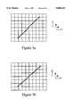
- FIGS. 6a and 6bshow a comparison of the voltage-flux (V- ⁇ ) characteristics of the prior art and improved SQUID sensors.
- FIG. 6ashows the V- ⁇ characteristic of the prior art SQUID sensor of FIG. 1.
- FIG. 6bshows the V- ⁇ characteristic of the improved SQUID sensor of FIG. 2.
- a SQUIDdetects magnetic fields by counting the number of flux quanta that are applied to the SQUID loop.
- magnetic fields and currentsare related.
- a current flowing in a diamagnetic conductorproduces a magnetic field, and a magnetic field induces a current in a nearby diamagnetic conductor.
- the induced currentflows in a direction which produces a magnetic field opposed to the original magnetic field, so that the resulting magnetic field is lowered.
- the response of the materialis imperfect, that is, the induced current decays and the resulting magnetic field regains its full value a short time after the initial current is applied.
- Superconductorsare perfect diamagnets, so a perfect ring of superconductor will not allow the magnetic flux inside the ring to change at all. This is a thermodynamic property of superconductors. When exposed to a magnetic field, a supercurrent is induced in the ring, and the supercurrent exactly counters the magnetic field to which it is exposed. Thus, in principle, measuring the current flowing in the superconducting ring gives the magnetic field strength near the superconductor.
- Superconductorshave limits, as do all physical things. Superconductors only superconduct below a critical, or transition, temperature T c . They also "go normal” or lose their superconducting properties when the current flowing through them exceeds a critical current, I c ; this is often expressed at the critical current density (J c ) of the material. Finally, superconductors can repel only so much magnetic flux before undergoing the transition back to normal materials. The maximum magnetic field a superconductor can take before this transition is called the critical field, H c . These three properties of a superconductor are related. At temperatures close to T c or in a high magnetic field a superconductor can carry less current than its theoretical maximum, and so forth.
- SQUIDstake advantage of these limits. They incorporate one or two weak-link junctions (labeled “E” in FIGS. 1 and 2) into the SQUID loop (A). These junctions (E) may be any kind of weak link, and their nature and number will depend on the particular circuit design. If fabricated using niobium technology, they would be tunneling Josephson junctions or superconductor-normal-superconductor (SNS) junctions. The Nb tunnel junctions also require a pair of shunt resistors. For high-temperature superconductive (HTS) applications, the junctions may be SNS, step-edge, grain boundary, or thinned weak links. Such junctions are referred to as "weak links" because they are the locations most likely to go normal.
- SSLsuperconductor-normal-superconductor
- the SQUIDsmay be fabricated from any superconductor, as long as the operating temperature of the sensor is kept below the superconducting transition temperature of the material chosen.
- Appropriate materialsinclude both conventional superconductors and high-temperature superconductors.
- Conventional superconductorsare usually metallic and have superconducting transition temperatures below about 23K. They include all of the elemental superconductors, the Chevrel phases, NbN, Nb 3 Ge, Nb 3 Sn, and other A15 compounds.
- High-temperature superconductorshave superconducting transition temperatures above about 23K and as high as about 133K. They are also known as oxide superconductors, cuprate superconductors, and perovskite superconductors because of their compositions and crystal structures.
- the current in the SQUID loopWhen exposed to a magnetic field, the current in the SQUID loop increases and decreases periodically as the field increases, with a period of one flux quantum. When this happens, there is a periodic rise and fall in the voltage that develops across the SQUID in response to the constant bias current applied by the control electronics. By measuring the size of the current that has to be applied to the feedback coil in order to keep the voltage developed across the SQUID constant, or alternatively by counting the oscillations of the voltage, the magnetic field strength can be calculated.
- the coupling between the feedback coil (D) and the SQUID loop (A)must be well defined.
- the feedback coil (D)is normally coupled inductively to the SQUID loop (A). As seen in FIG. 1, this is often accomplished by using a multi-turn coil over a secondary hole in the SQUID.
- a magnetic sensor for non-destructive testing/evaluation (NDT/NDE) or microscopyconsists of a SQUID (J) and a feedback coil (D).
- the SQUID (J)has a SQUID loop (A), part of which is called a pick-up loop (C), and one or two weak-link or Josephson junctions (E).
- ASQUID loop
- Cpick-up loop
- Eweak-link or Josephson junctions
- the pan of the SQUID loop (A) coupled to the feedback coil (D)can act as a secondary pick-up loop, coupling external magnetic fields into the SQUID.
- This secondary couplingcauses two problems.
- the firstis a loss of resolution.
- the position of the origin of a magnetic signalis determined by the position of the SQUID pick-up loop (C).
- a magnetic signal coupled to the SQUID (J) by the feedback structuremay have a different origin, in which case the mapping of magnetic signal to physical location will be distorted.
- a second problemis a reduction in signal to noise ratio (SNR).
- SNRsignal to noise ratio
- the desired signalcomes from a small area to increase spatial resolution, the SQUID must be very sensitive. If the feedback structure is much larger than the pick-up loop it may couple more strongly to an extraneous background signal, such as the earth's magnetic field. This spurious signal may be of the same order as the desired signal, or may be even stronger. In this case, the SQUID may be overloaded by the spurious signal.
- FIG. 2The improved SQUID coupling structure of the instant invention is shown schematically in FIG. 2.
- a superconducting Found planeB
- FIG. 3ais a cross-section taken through the body of the SQUID along line 1--1 of FIG. 2.
- the ground plane (B)excludes the magnetic fields (H) from the SQUID loop (A) and the feedback loop (D).
- FIG. 3bshows a cross-section taken along line 2--2 of FIG. 2, through the pick-up loop (C).
- the magnetic field (H)penetrates the opening in the pick-up loop (C) where it is detected by the SQUID.
- magnetic fields (H) perpendicular to the ground plane and to the plane of the SQUIDcan penetrate only in the area of the pick-up loop. This limits the field of view to the desired area of the plane.
- the SQUID loopis entirely planar, magnetic fields in the plane of the ground plane do not introduce any flux into the SQUID. Electrical connections are made to the SQUID loop at the counterelectrode of junctions (E) and via its connection to the ground plane (F).
- a further advantage of the improved coupling structureis that the sample being measured is less disturbed by the magnetic field produced by the feedback loop (D) than it is by the field of feedback coils of conventional SQUIDs.
- This advantageresults from the bifilar geometry of the feedback coil and from the proximity of the ground plane, which give rise to a smaller leakage of field than does the conventional spiral coil.
- the improved sensoris shielded by the superconducting ground plane from external magnetic fields perpendicular to its plane there are no components of magnetic field that can couple to the SQUID except in the region of the pick-up loop, that is, the region of interest.
- a second ground plane (G)shown lifted off the structure in FIG. 2, can be added to improve the shielding of the SQUID loop (A) and the feedback coil (D).
- the resulting structureis an example of a stripline, rather than a microstripline, configuration.
- Another optional addition to the basic schemeis a bias connection (F) between the ground plane (B) in FIG. 2, and the SQUID loop (A).
- FIG. 4shows an equivalent circuit of the improved SQUID sensor.
- the pick-up loop (C)lies partially outside the region shielded by the ground plane (B) and is exposed to a magnetic flux.
- the SQUID junctions (E)are shielded from all other fields.
- a feedback loop (D)is inductively coupled to the SQUID loop (A) to allow for flux-locked loop operation. During operation, a field is applied to the SQUID using the feedback coil to counteract the effect of the detected magnetic flux.
- the feedback electronicsmonitors the amount of current applied and converts the current to a magnetic field measurement.
- FIGS. 5a, 5b, 6a and 6bshow performance data of the prior art and improved SQUID sensors.
- An ideal SQUIDhas an I-V characteristic (compare FIGS. 5a and 5b) that is vertical at zero voltage, bends smoothly at the critical current I c , and then has a linear I-V relationship (constant resistance).
- the V- ⁇ characteristic of an ideal SQUIDis smooth and approximately sinusoidal, with each period of the sinusoid corresponding to the application of a single flux quantum to the SQUID.
- the I-V characteristic of the prior art SQUID sensor of FIG. 1, seen in FIG. 5ashows substantial deviations from ideality. Its complex structure induces radio frequency resonances that show up as steps in the nominally linear portion of the I-V curve. In contrast, the I-V characteristic of the improved SQUID sensor of FIG. 2 (FIG. 5b) is much more ideal.
- FIG. 6ashows the V- ⁇ characteristic of the prior art SQUID sensor of FIG. 1.
- FIG. 6bshows the V- ⁇ characteristic of the improved SQUID sensor of FIG. 2.
- the characteristicis substantially sinusoidal over a wide range of SQUID bias currents.
- the improved coupling scheme for SQUID sensorsallows coupling of the feedback loop to the SQUID loop by mutual inductance while restricting the coupling of the SQUID to external magnetic fields and confining the effect of the feedback loop to the SQUID.
Landscapes
- Physics & Mathematics (AREA)
- Condensed Matter Physics & Semiconductors (AREA)
- General Physics & Mathematics (AREA)
- Superconductor Devices And Manufacturing Methods Thereof (AREA)
- Measuring Magnetic Variables (AREA)
Abstract
Description
Claims (9)
Priority Applications (1)
| Application Number | Priority Date | Filing Date | Title |
|---|---|---|---|
| US08/403,728US5600243A (en) | 1993-09-07 | 1993-09-07 | Magnetically shielded magnetic sensor with squid and ground plane |
Applications Claiming Priority (2)
| Application Number | Priority Date | Filing Date | Title |
|---|---|---|---|
| US08/403,728US5600243A (en) | 1993-09-07 | 1993-09-07 | Magnetically shielded magnetic sensor with squid and ground plane |
| PCT/US1993/008496WO1995007470A2 (en) | 1993-09-07 | 1993-09-07 | Improved squid coupling structure |
Publications (1)
| Publication Number | Publication Date |
|---|---|
| US5600243Atrue US5600243A (en) | 1997-02-04 |
Family
ID=34810736
Family Applications (1)
| Application Number | Title | Priority Date | Filing Date |
|---|---|---|---|
| US08/403,728Expired - Fee RelatedUS5600243A (en) | 1993-09-07 | 1993-09-07 | Magnetically shielded magnetic sensor with squid and ground plane |
Country Status (1)
| Country | Link |
|---|---|
| US (1) | US5600243A (en) |
Cited By (19)
| Publication number | Priority date | Publication date | Assignee | Title |
|---|---|---|---|---|
| WO1999001779A3 (en)* | 1997-06-30 | 1999-04-01 | Forschungszentrum Juelich Gmbh | Magnetic flux sensor with annular probe |
| US6072383A (en)* | 1998-11-04 | 2000-06-06 | Checkpoint Systems, Inc. | RFID tag having parallel resonant circuit for magnetically decoupling tag from its environment |
| US6208235B1 (en) | 1997-03-24 | 2001-03-27 | Checkpoint Systems, Inc. | Apparatus for magnetically decoupling an RFID tag |
| US6483304B1 (en)* | 1997-03-13 | 2002-11-19 | Ricoh Company, Ltd. | Magnetic field probe having a shielding and isolating layers to protect lead wires extending between a coil and pads |
| WO2003048797A1 (en)* | 2001-11-27 | 2003-06-12 | Forschungszentrum Jülich GmbH | Squid microscope for room temperature samples |
| US20040027125A1 (en)* | 2002-02-06 | 2004-02-12 | John Clarke | SQUID detected NMR and MRI at ultralow fields |
| US20040135734A1 (en)* | 2002-10-30 | 2004-07-15 | Kouichi Uesaka | Narrow-directivity electromagnetic-field antenna probe, and electromagnetic-field measurement apparatus, electric-current distribution search-for apparatus or electrical-wiring diagnosis apparatus using this antenna probe |
| US20040160815A1 (en)* | 2002-01-24 | 2004-08-19 | Kazuto Hirata | High-sensitivity magnetic field sensor |
| US20080221430A1 (en)* | 2007-03-07 | 2008-09-11 | Hisaaki Ochi | Apparatus for magnetic resonance imaging |
| US8970217B1 (en) | 2010-04-14 | 2015-03-03 | Hypres, Inc. | System and method for noise reduction in magnetic resonance imaging |
| US9136457B2 (en) | 2006-09-20 | 2015-09-15 | Hypres, Inc. | Double-masking technique for increasing fabrication yield in superconducting electronics |
| US9618591B1 (en) | 2009-11-24 | 2017-04-11 | Hypres, Inc. | Magnetic resonance system and method employing a digital squid |
| US11273283B2 (en) | 2017-12-31 | 2022-03-15 | Neuroenhancement Lab, LLC | Method and apparatus for neuroenhancement to enhance emotional response |
| US11364361B2 (en) | 2018-04-20 | 2022-06-21 | Neuroenhancement Lab, LLC | System and method for inducing sleep by transplanting mental states |
| US11452839B2 (en) | 2018-09-14 | 2022-09-27 | Neuroenhancement Lab, LLC | System and method of improving sleep |
| US11717686B2 (en) | 2017-12-04 | 2023-08-08 | Neuroenhancement Lab, LLC | Method and apparatus for neuroenhancement to facilitate learning and performance |
| US11723579B2 (en) | 2017-09-19 | 2023-08-15 | Neuroenhancement Lab, LLC | Method and apparatus for neuroenhancement |
| US11786694B2 (en) | 2019-05-24 | 2023-10-17 | NeuroLight, Inc. | Device, method, and app for facilitating sleep |
| US12280219B2 (en) | 2017-12-31 | 2025-04-22 | NeuroLight, Inc. | Method and apparatus for neuroenhancement to enhance emotional response |
Citations (6)
| Publication number | Priority date | Publication date | Assignee | Title |
|---|---|---|---|---|
| EP0313132A2 (en)* | 1987-10-22 | 1989-04-26 | Philips Patentverwaltung GmbH | Device for multichannel measuring of weak magnetic fields |
| EP0327123A2 (en)* | 1988-02-05 | 1989-08-09 | Hitachi, Ltd. | Superconducting quantum interference device |
| US5185527A (en)* | 1990-12-10 | 1993-02-09 | Westinghouse Electric Corp. | Multispectral superconductive quantum detector |
| EP0567386A2 (en)* | 1992-04-20 | 1993-10-27 | Sumitomo Electric Industries, Ltd. | Planar magnetism sensor utilizing a squid of oxide superconductor |
| US5287057A (en)* | 1991-03-19 | 1994-02-15 | Fujitsu Limited | Superconducting circuit having a rectifier for converting a bipolar signal to a unipolar signal |
| US5319307A (en)* | 1990-08-31 | 1994-06-07 | Quantum Magnetics, Inc. | Geometrically and electrically balanaced dc SQUID system having a pair of intersecting slits |
- 1993
- 1993-09-07USUS08/403,728patent/US5600243A/ennot_activeExpired - Fee Related
Patent Citations (7)
| Publication number | Priority date | Publication date | Assignee | Title |
|---|---|---|---|---|
| EP0313132A2 (en)* | 1987-10-22 | 1989-04-26 | Philips Patentverwaltung GmbH | Device for multichannel measuring of weak magnetic fields |
| US5012190A (en)* | 1987-10-22 | 1991-04-30 | U.S. Philips Corporation | Apparatus for multi-channel measurement of weak magnetic fields with squids and superconducting gradiometers on individual detachable assemblies, and method of manufacture |
| EP0327123A2 (en)* | 1988-02-05 | 1989-08-09 | Hitachi, Ltd. | Superconducting quantum interference device |
| US5319307A (en)* | 1990-08-31 | 1994-06-07 | Quantum Magnetics, Inc. | Geometrically and electrically balanaced dc SQUID system having a pair of intersecting slits |
| US5185527A (en)* | 1990-12-10 | 1993-02-09 | Westinghouse Electric Corp. | Multispectral superconductive quantum detector |
| US5287057A (en)* | 1991-03-19 | 1994-02-15 | Fujitsu Limited | Superconducting circuit having a rectifier for converting a bipolar signal to a unipolar signal |
| EP0567386A2 (en)* | 1992-04-20 | 1993-10-27 | Sumitomo Electric Industries, Ltd. | Planar magnetism sensor utilizing a squid of oxide superconductor |
Cited By (36)
| Publication number | Priority date | Publication date | Assignee | Title |
|---|---|---|---|---|
| US6483304B1 (en)* | 1997-03-13 | 2002-11-19 | Ricoh Company, Ltd. | Magnetic field probe having a shielding and isolating layers to protect lead wires extending between a coil and pads |
| US6696834B2 (en) | 1997-03-13 | 2004-02-24 | Ricoh Company, Ltd. | Magnetic field probe having a shielding layer to protect lead wires with an isolating layer |
| US6208235B1 (en) | 1997-03-24 | 2001-03-27 | Checkpoint Systems, Inc. | Apparatus for magnetically decoupling an RFID tag |
| WO1999001779A3 (en)* | 1997-06-30 | 1999-04-01 | Forschungszentrum Juelich Gmbh | Magnetic flux sensor with annular probe |
| US6072383A (en)* | 1998-11-04 | 2000-06-06 | Checkpoint Systems, Inc. | RFID tag having parallel resonant circuit for magnetically decoupling tag from its environment |
| WO2003048797A1 (en)* | 2001-11-27 | 2003-06-12 | Forschungszentrum Jülich GmbH | Squid microscope for room temperature samples |
| US20050116719A1 (en)* | 2001-11-27 | 2005-06-02 | Mehdi Fardmanesh | Squid microscope for room temperature samples |
| US6847546B2 (en)* | 2002-01-24 | 2005-01-25 | National Institute For Materials Science | High-sensitivity magnetic field sensor |
| US20040160815A1 (en)* | 2002-01-24 | 2004-08-19 | Kazuto Hirata | High-sensitivity magnetic field sensor |
| US6885192B2 (en) | 2002-02-06 | 2005-04-26 | The Regents Of The University Of California | SQUID detected NMR and MRI at ultralow fields |
| US7466132B2 (en) | 2002-02-06 | 2008-12-16 | The Regents Of The University Of California | Squid detected NMR and MRI at ultralow fields |
| US20050134262A1 (en)* | 2002-02-06 | 2005-06-23 | John Clarke | Squid detected NMR and MRI at ultralow fields |
| US7053610B2 (en) | 2002-02-06 | 2006-05-30 | The Regents Of Th University Of California | Squid detected NMR and MRI at ultralow fields |
| US20080074113A1 (en)* | 2002-02-06 | 2008-03-27 | John Clarke | Squid detected nmr and mri at ultralow fields |
| US20040027125A1 (en)* | 2002-02-06 | 2004-02-12 | John Clarke | SQUID detected NMR and MRI at ultralow fields |
| US20040135734A1 (en)* | 2002-10-30 | 2004-07-15 | Kouichi Uesaka | Narrow-directivity electromagnetic-field antenna probe, and electromagnetic-field measurement apparatus, electric-current distribution search-for apparatus or electrical-wiring diagnosis apparatus using this antenna probe |
| US7132997B2 (en)* | 2002-10-30 | 2006-11-07 | Hitachi, Ltd. | Narrow-directivity electromagnetic-field antenna probe, and electromagnetic-field measurement apparatus, electric-current distribution search-for apparatus or electrical-wiring diagnosis apparatus using this antenna probe |
| US9136457B2 (en) | 2006-09-20 | 2015-09-15 | Hypres, Inc. | Double-masking technique for increasing fabrication yield in superconducting electronics |
| US9595656B2 (en) | 2006-09-20 | 2017-03-14 | Hypres, Inc. | Double-masking technique for increasing fabrication yield in superconducting electronics |
| US10109673B2 (en) | 2006-09-20 | 2018-10-23 | Hypres, Inc. | Double-masking technique for increasing fabrication yield in superconducting electronics |
| US20080221430A1 (en)* | 2007-03-07 | 2008-09-11 | Hisaaki Ochi | Apparatus for magnetic resonance imaging |
| US10509084B1 (en) | 2009-11-24 | 2019-12-17 | Hypres, Inc. | Magnetic resonance system and method employing a digital SQUID |
| US9618591B1 (en) | 2009-11-24 | 2017-04-11 | Hypres, Inc. | Magnetic resonance system and method employing a digital squid |
| US8970217B1 (en) | 2010-04-14 | 2015-03-03 | Hypres, Inc. | System and method for noise reduction in magnetic resonance imaging |
| US10502802B1 (en) | 2010-04-14 | 2019-12-10 | Hypres, Inc. | System and method for noise reduction in magnetic resonance imaging |
| US11723579B2 (en) | 2017-09-19 | 2023-08-15 | Neuroenhancement Lab, LLC | Method and apparatus for neuroenhancement |
| US11717686B2 (en) | 2017-12-04 | 2023-08-08 | Neuroenhancement Lab, LLC | Method and apparatus for neuroenhancement to facilitate learning and performance |
| US11273283B2 (en) | 2017-12-31 | 2022-03-15 | Neuroenhancement Lab, LLC | Method and apparatus for neuroenhancement to enhance emotional response |
| US11318277B2 (en) | 2017-12-31 | 2022-05-03 | Neuroenhancement Lab, LLC | Method and apparatus for neuroenhancement to enhance emotional response |
| US11478603B2 (en) | 2017-12-31 | 2022-10-25 | Neuroenhancement Lab, LLC | Method and apparatus for neuroenhancement to enhance emotional response |
| US12280219B2 (en) | 2017-12-31 | 2025-04-22 | NeuroLight, Inc. | Method and apparatus for neuroenhancement to enhance emotional response |
| US12383696B2 (en) | 2017-12-31 | 2025-08-12 | NeuroLight, Inc. | Method and apparatus for neuroenhancement to enhance emotional response |
| US12397128B2 (en) | 2017-12-31 | 2025-08-26 | NeuroLight, Inc. | Method and apparatus for neuroenhancement to enhance emotional response |
| US11364361B2 (en) | 2018-04-20 | 2022-06-21 | Neuroenhancement Lab, LLC | System and method for inducing sleep by transplanting mental states |
| US11452839B2 (en) | 2018-09-14 | 2022-09-27 | Neuroenhancement Lab, LLC | System and method of improving sleep |
| US11786694B2 (en) | 2019-05-24 | 2023-10-17 | NeuroLight, Inc. | Device, method, and app for facilitating sleep |
Similar Documents
| Publication | Publication Date | Title |
|---|---|---|
| US5600243A (en) | Magnetically shielded magnetic sensor with squid and ground plane | |
| Mahdi et al. | Some new horizons in magnetic sensing: high-Tc SQUIDs, GMR and GMI materials | |
| CA2829934C (en) | Superconducting quantum interference device | |
| US5173660A (en) | Packaged squid system with integral superconducting shielding layer | |
| Stolz et al. | Long baseline LTS SQUID gradiometers with sub-μm sized Josephson junctions | |
| US11249148B2 (en) | Magnetic flux pickup and electronic device for sensing magnetic fields | |
| Sochnikov et al. | dc SQUID design with femtotesla sensitivity for quantum-ready readouts | |
| US7521708B1 (en) | High sensitivity ring-SQUID magnetic sensor | |
| Faley et al. | DC-SQUID magnetometers and gradiometers on the basis of quasiplanar ramp-type Josephson junctions | |
| US11255929B2 (en) | Electronic device for sensing magnetic fields | |
| WO1995007470A2 (en) | Improved squid coupling structure | |
| Ho et al. | SQUID microscopy for mapping vector magnetic fields | |
| Shanehsazzadeh et al. | High Tc SQUID based magnetocardiography system in unshielded environment | |
| Flokstra et al. | SQUIDs | |
| Bick et al. | Highly balanced long-baseline axial gradiometer based on high-T/sub c/superconducting tape | |
| Granata et al. | Low critical temperature dc-SQUIDs for high spatial resolution applications | |
| Wellstood et al. | Thin-film flux transformers of YBa/sub 2/Cu/sub 3/O/sub 7-x | |
| Kawano et al. | Development of non-destructive evaluation system using an HTS-SQUID gradiometer for magnetized materials | |
| Donaldson et al. | Progress in high Tc magnetic sensors and their applications | |
| AU2003250576B2 (en) | Superconducting quantum interference device | |
| Lee et al. | Magnetocardiographic performance of single-layer second-order YBCO SQUID gradiometers | |
| Carr et al. | HTS dc SQUIDs for eddy current NDE in an unshielded environment | |
| Carr et al. | Advances in the Use of LTS and HTS SQUIDS in Electromagnetic NDE | |
| Claycomb et al. | Superconducting and high-permeability shields modeled for biomagnetism and nondestructive testing | |
| Faley et al. | Superconducting quantum interference devices based on YBa2Cu3O7–x films for nondestructive testing |
Legal Events
| Date | Code | Title | Description |
|---|---|---|---|
| AS | Assignment | Owner name:CONDUCTUS, INC., CALIFORNIA Free format text:ASSIGNMENT OF ASSIGNORS INTEREST;ASSIGNOR:COLCLOUGH, MARK S.;REEL/FRAME:007404/0694 Effective date:19950324 | |
| AS | Assignment | Owner name:SILICON VALLEY BANK, CALIFORNIA Free format text:ASSIGNMENT OF ASSIGNORS INTEREST;ASSIGNOR:CONDUCTUS, INC.;REEL/FRAME:009257/0846 Effective date:19980423 | |
| AS | Assignment | Owner name:TRANSAMERICA BUSINESS CREDIT CORP., CONNECTICUT Free format text:SECURITY INTEREST;ASSIGNOR:CONDUCTUS, INC.;REEL/FRAME:009375/0683 Effective date:19980529 | |
| FEPP | Fee payment procedure | Free format text:PAT HLDR NO LONGER CLAIMS SMALL ENT STAT AS SMALL BUSINESS (ORIGINAL EVENT CODE: LSM2); ENTITY STATUS OF PATENT OWNER: LARGE ENTITY | |
| FPAY | Fee payment | Year of fee payment:4 | |
| AS | Assignment | Owner name:AGILITY CAPITAL, LLC, CALIFORNIA Free format text:SECURITY AGREEMENT;ASSIGNOR:CONDUCTUS, INC.;REEL/FRAME:015271/0198 Effective date:20040426 | |
| REMI | Maintenance fee reminder mailed | ||
| AS | Assignment | Owner name:CONDUCTUS, INC., CALIFORNIA Free format text:RELEASE OF SECURITY AGREEMENT;ASSIGNOR:AGILITY CAPITAL, LLC;REEL/FRAME:015851/0193 Effective date:20040526 | |
| FEPP | Fee payment procedure | Free format text:PETITION RELATED TO MAINTENANCE FEES FILED (ORIGINAL EVENT CODE: PMFP); ENTITY STATUS OF PATENT OWNER: LARGE ENTITY | |
| FEPP | Fee payment procedure | Free format text:PETITION RELATED TO MAINTENANCE FEES FILED (ORIGINAL EVENT CODE: PMFP); ENTITY STATUS OF PATENT OWNER: LARGE ENTITY | |
| REIN | Reinstatement after maintenance fee payment confirmed | ||
| FP | Lapsed due to failure to pay maintenance fee | Effective date:20050204 | |
| FPAY | Fee payment | Year of fee payment:8 | |
| SULP | Surcharge for late payment | ||
| FEPP | Fee payment procedure | Free format text:PETITION RELATED TO MAINTENANCE FEES GRANTED (ORIGINAL EVENT CODE: PMFG); ENTITY STATUS OF PATENT OWNER: LARGE ENTITY | |
| PRDP | Patent reinstated due to the acceptance of a late maintenance fee | Effective date:20060110 | |
| REMI | Maintenance fee reminder mailed | ||
| LAPS | Lapse for failure to pay maintenance fees | ||
| STCH | Information on status: patent discontinuation | Free format text:PATENT EXPIRED DUE TO NONPAYMENT OF MAINTENANCE FEES UNDER 37 CFR 1.362 | |
| FP | Lapsed due to failure to pay maintenance fee | Effective date:20090204 |