US5599300A - Method for electrosurgically obtaining access to the biliary tree with an adjustably positionable needle-knife - Google Patents
Method for electrosurgically obtaining access to the biliary tree with an adjustably positionable needle-knifeDownload PDFInfo
- Publication number
- US5599300A US5599300AUS08/440,562US44056295AUS5599300AUS 5599300 AUS5599300 AUS 5599300AUS 44056295 AUS44056295 AUS 44056295AUS 5599300 AUS5599300 AUS 5599300A
- Authority
- US
- United States
- Prior art keywords
- catheter
- lumen
- knife
- needle
- distal end
- Prior art date
- Legal status (The legal status is an assumption and is not a legal conclusion. Google has not performed a legal analysis and makes no representation as to the accuracy of the status listed.)
- Expired - Lifetime
Links
- 238000000034methodMethods0.000titleclaimsabstractdescription84
- 210000003445biliary tractAnatomy0.000titleclaimsabstractdescription17
- 239000002872contrast mediaSubstances0.000claimsabstractdescription50
- 210000001953common bile ductAnatomy0.000claimsdescription18
- 210000001198duodenumAnatomy0.000claimsdescription5
- 230000007246mechanismEffects0.000abstractdescription14
- 238000001802infusionMethods0.000abstractdescription8
- 238000007459endoscopic retrograde cholangiopancreatographyMethods0.000description31
- 238000000576coating methodMethods0.000description26
- 239000011248coating agentSubstances0.000description23
- 239000000975dyeSubstances0.000description23
- 238000002347injectionMethods0.000description20
- 239000007924injectionSubstances0.000description20
- 239000004575stoneSubstances0.000description20
- 238000012800visualizationMethods0.000description20
- 239000000463materialSubstances0.000description11
- 210000001519tissueAnatomy0.000description11
- 210000000277pancreatic ductAnatomy0.000description10
- 239000012530fluidSubstances0.000description9
- 238000003780insertionMethods0.000description8
- 230000037431insertionEffects0.000description8
- 239000000700radioactive tracerSubstances0.000description8
- 208000037062PolypsDiseases0.000description7
- 239000000203mixtureSubstances0.000description7
- YMWUJEATGCHHMB-UHFFFAOYSA-NDichloromethaneChemical compoundClCClYMWUJEATGCHHMB-UHFFFAOYSA-N0.000description6
- 239000004809TeflonSubstances0.000description6
- 229920006362Teflon®Polymers0.000description6
- TZCXTZWJZNENPQ-UHFFFAOYSA-Lbarium sulfateChemical compound[Ba+2].[O-]S([O-])(=O)=OTZCXTZWJZNENPQ-UHFFFAOYSA-L0.000description6
- 239000000994contrast dyeSubstances0.000description6
- 230000008569processEffects0.000description6
- 229920002614Polyether block amidePolymers0.000description5
- 230000008901benefitEffects0.000description5
- 210000001096cystic ductAnatomy0.000description5
- 230000009977dual effectEffects0.000description5
- 229910052741iridiumInorganic materials0.000description5
- GKOZUEZYRPOHIO-UHFFFAOYSA-Niridium atomChemical compound[Ir]GKOZUEZYRPOHIO-UHFFFAOYSA-N0.000description5
- 239000000243solutionSubstances0.000description5
- 238000003756stirringMethods0.000description5
- 229920000571Nylon 11Polymers0.000description4
- 229920003171Poly (ethylene oxide)Polymers0.000description4
- 229910001566austeniteInorganic materials0.000description4
- 210000000941bileAnatomy0.000description4
- 238000001574biopsyMethods0.000description4
- 230000010339dilationEffects0.000description4
- 210000003811fingerAnatomy0.000description4
- 238000002594fluoroscopyMethods0.000description4
- 230000006870functionEffects0.000description4
- 210000005095gastrointestinal systemAnatomy0.000description4
- 229910000734martensiteInorganic materials0.000description4
- VPRUMANMDWQMNF-UHFFFAOYSA-Nphenylethane boronic acidChemical compoundOB(O)CCC1=CC=CC=C1VPRUMANMDWQMNF-UHFFFAOYSA-N0.000description4
- 238000001356surgical procedureMethods0.000description4
- 210000003813thumbAnatomy0.000description4
- 208000031481Pathologic ConstrictionDiseases0.000description3
- FAPWRFPIFSIZLT-UHFFFAOYSA-MSodium chlorideChemical compound[Na+].[Cl-]FAPWRFPIFSIZLT-UHFFFAOYSA-M0.000description3
- 230000008859changeEffects0.000description3
- 201000001883cholelithiasisDiseases0.000description3
- 230000001112coagulating effectEffects0.000description3
- 238000002405diagnostic procedureMethods0.000description3
- 239000000835fiberSubstances0.000description3
- 230000003287optical effectEffects0.000description3
- 229920005989resinPolymers0.000description3
- 239000011347resinSubstances0.000description3
- 239000010935stainless steelSubstances0.000description3
- 229910001220stainless steelInorganic materials0.000description3
- 238000002560therapeutic procedureMethods0.000description3
- 229910001369BrassInorganic materials0.000description2
- 239000004677NylonSubstances0.000description2
- 239000004642PolyimideSubstances0.000description2
- 239000000853adhesiveSubstances0.000description2
- 230000001070adhesive effectEffects0.000description2
- 239000010951brassSubstances0.000description2
- 210000003459common hepatic ductAnatomy0.000description2
- 238000010276constructionMethods0.000description2
- 239000013078crystalSubstances0.000description2
- 238000000605extractionMethods0.000description2
- 208000001130gallstonesDiseases0.000description2
- 230000002496gastric effectEffects0.000description2
- 229910001092metal group alloyInorganic materials0.000description2
- 210000003205muscleAnatomy0.000description2
- 229920001778nylonPolymers0.000description2
- 229920001721polyimidePolymers0.000description2
- 229920000642polymerPolymers0.000description2
- 229920002635polyurethanePolymers0.000description2
- 239000004814polyurethaneSubstances0.000description2
- 238000005070samplingMethods0.000description2
- 230000000472traumatic effectEffects0.000description2
- 229930003347AtropineNatural products0.000description1
- 102000051325GlucagonHuman genes0.000description1
- 108060003199GlucagonProteins0.000description1
- RKUNBYITZUJHSG-UHFFFAOYSA-NHyosciamin-hydrochloridNatural productsCN1C(C2)CCC1CC2OC(=O)C(CO)C1=CC=CC=C1RKUNBYITZUJHSG-UHFFFAOYSA-N0.000description1
- NNJVILVZKWQKPM-UHFFFAOYSA-NLidocaineChemical compoundCCN(CC)CC(=O)NC1=C(C)C=CC=C1CNNJVILVZKWQKPM-UHFFFAOYSA-N0.000description1
- 206010033645PancreatitisDiseases0.000description1
- 239000004952PolyamideSubstances0.000description1
- 206010039897SedationDiseases0.000description1
- 239000002390adhesive tapeSubstances0.000description1
- 230000000712assemblyEffects0.000description1
- 238000000429assemblyMethods0.000description1
- RKUNBYITZUJHSG-SPUOUPEWSA-NatropineChemical compoundO([C@H]1C[C@H]2CC[C@@H](C1)N2C)C(=O)C(CO)C1=CC=CC=C1RKUNBYITZUJHSG-SPUOUPEWSA-N0.000description1
- 229960000396atropineDrugs0.000description1
- 230000006399behaviorEffects0.000description1
- 238000005452bendingMethods0.000description1
- 210000000013bile ductAnatomy0.000description1
- 210000001124body fluidAnatomy0.000description1
- 239000010839body fluidSubstances0.000description1
- 230000036760body temperatureEffects0.000description1
- 238000002192cholecystectomyMethods0.000description1
- 230000003749cleanlinessEffects0.000description1
- 229920001688coating polymerPolymers0.000description1
- 238000001816coolingMethods0.000description1
- 238000003745diagnosisMethods0.000description1
- 238000012631diagnostic techniqueMethods0.000description1
- AAOVKJBEBIDNHE-UHFFFAOYSA-NdiazepamChemical compoundN=1CC(=O)N(C)C2=CC=C(Cl)C=C2C=1C1=CC=CC=C1AAOVKJBEBIDNHE-UHFFFAOYSA-N0.000description1
- 229960003529diazepamDrugs0.000description1
- 230000000916dilatatory effectEffects0.000description1
- 230000002183duodenal effectEffects0.000description1
- 230000000694effectsEffects0.000description1
- 238000011846endoscopic investigationMethods0.000description1
- 150000002148estersChemical class0.000description1
- 238000001125extrusionMethods0.000description1
- 229920002457flexible plasticPolymers0.000description1
- 210000005224forefingerAnatomy0.000description1
- 238000002695general anesthesiaMethods0.000description1
- MASNOZXLGMXCHN-ZLPAWPGGSA-NglucagonChemical compoundC([C@@H](C(=O)N[C@H](C(=O)N[C@@H](CCC(N)=O)C(=O)N[C@@H](CC=1C2=CC=CC=C2NC=1)C(=O)N[C@@H](CC(C)C)C(=O)N[C@@H](CCSC)C(=O)N[C@@H](CC(N)=O)C(=O)N[C@@H]([C@@H](C)O)C(O)=O)C(C)C)NC(=O)[C@H](CC(O)=O)NC(=O)[C@H](CCC(N)=O)NC(=O)[C@H](C)NC(=O)[C@H](CCCNC(N)=N)NC(=O)[C@H](CCCNC(N)=N)NC(=O)[C@H](CO)NC(=O)[C@H](CC(O)=O)NC(=O)[C@H](CC(C)C)NC(=O)[C@H](CC=1C=CC(O)=CC=1)NC(=O)[C@H](CCCCN)NC(=O)[C@H](CO)NC(=O)[C@H](CC=1C=CC(O)=CC=1)NC(=O)[C@H](CC(O)=O)NC(=O)[C@H](CO)NC(=O)[C@@H](NC(=O)[C@H](CC=1C=CC=CC=1)NC(=O)[C@@H](NC(=O)CNC(=O)[C@H](CCC(N)=O)NC(=O)[C@H](CO)NC(=O)[C@@H](N)CC=1NC=NC=1)[C@@H](C)O)[C@@H](C)O)C1=CC=CC=C1MASNOZXLGMXCHN-ZLPAWPGGSA-N0.000description1
- 229960004666glucagonDrugs0.000description1
- 238000010348incorporationMethods0.000description1
- 230000036512infertilityEffects0.000description1
- 210000000936intestineAnatomy0.000description1
- 238000012977invasive surgical procedureMethods0.000description1
- 210000002429large intestineAnatomy0.000description1
- 229960004194lidocaineDrugs0.000description1
- 238000002686lithotriptorMethods0.000description1
- 238000004519manufacturing processMethods0.000description1
- 229910052751metalInorganic materials0.000description1
- 239000002184metalSubstances0.000description1
- 150000002739metalsChemical class0.000description1
- 231100000252nontoxicToxicity0.000description1
- 230000003000nontoxic effectEffects0.000description1
- 210000003300oropharynxAnatomy0.000description1
- 238000012856packingMethods0.000description1
- 210000000496pancreasAnatomy0.000description1
- 230000000737periodic effectEffects0.000description1
- 229920002647polyamidePolymers0.000description1
- 229940071643prefilled syringeDrugs0.000description1
- 238000009877renderingMethods0.000description1
- 230000036280sedationEffects0.000description1
- 210000005070sphincterAnatomy0.000description1
- 230000000699topical effectEffects0.000description1
- 230000009466transformationEffects0.000description1
- 230000000007visual effectEffects0.000description1
Images


Classifications
- A—HUMAN NECESSITIES
- A61—MEDICAL OR VETERINARY SCIENCE; HYGIENE
- A61M—DEVICES FOR INTRODUCING MEDIA INTO, OR ONTO, THE BODY; DEVICES FOR TRANSDUCING BODY MEDIA OR FOR TAKING MEDIA FROM THE BODY; DEVICES FOR PRODUCING OR ENDING SLEEP OR STUPOR
- A61M25/00—Catheters; Hollow probes
- A61M25/0021—Catheters; Hollow probes characterised by the form of the tubing
- A61M25/0023—Catheters; Hollow probes characterised by the form of the tubing by the form of the lumen, e.g. cross-section, variable diameter
- A61M25/0026—Multi-lumen catheters with stationary elements
- A—HUMAN NECESSITIES
- A61—MEDICAL OR VETERINARY SCIENCE; HYGIENE
- A61B—DIAGNOSIS; SURGERY; IDENTIFICATION
- A61B18/00—Surgical instruments, devices or methods for transferring non-mechanical forms of energy to or from the body
- A61B18/04—Surgical instruments, devices or methods for transferring non-mechanical forms of energy to or from the body by heating
- A61B18/12—Surgical instruments, devices or methods for transferring non-mechanical forms of energy to or from the body by heating by passing a current through the tissue to be heated, e.g. high-frequency current
- A61B18/14—Probes or electrodes therefor
- A61B18/1492—Probes or electrodes therefor having a flexible, catheter-like structure, e.g. for heart ablation
- A—HUMAN NECESSITIES
- A61—MEDICAL OR VETERINARY SCIENCE; HYGIENE
- A61B—DIAGNOSIS; SURGERY; IDENTIFICATION
- A61B18/00—Surgical instruments, devices or methods for transferring non-mechanical forms of energy to or from the body
- A61B18/04—Surgical instruments, devices or methods for transferring non-mechanical forms of energy to or from the body by heating
- A61B18/12—Surgical instruments, devices or methods for transferring non-mechanical forms of energy to or from the body by heating by passing a current through the tissue to be heated, e.g. high-frequency current
- A61B18/14—Probes or electrodes therefor
- A61B18/1477—Needle-like probes
- A—HUMAN NECESSITIES
- A61—MEDICAL OR VETERINARY SCIENCE; HYGIENE
- A61B—DIAGNOSIS; SURGERY; IDENTIFICATION
- A61B10/00—Instruments for taking body samples for diagnostic purposes; Other methods or instruments for diagnosis, e.g. for vaccination diagnosis, sex determination or ovulation-period determination; Throat striking implements
- A61B10/02—Instruments for taking cell samples or for biopsy
- A61B10/04—Endoscopic instruments, e.g. catheter-type instruments
- A61B2010/045—Needles
- A—HUMAN NECESSITIES
- A61—MEDICAL OR VETERINARY SCIENCE; HYGIENE
- A61B—DIAGNOSIS; SURGERY; IDENTIFICATION
- A61B17/00—Surgical instruments, devices or methods
- A61B17/22—Implements for squeezing-off ulcers or the like on inner organs of the body; Implements for scraping-out cavities of body organs, e.g. bones; for invasive removal or destruction of calculus using mechanical vibrations; for removing obstructions in blood vessels, not otherwise provided for
- A61B2017/22072—Implements for squeezing-off ulcers or the like on inner organs of the body; Implements for scraping-out cavities of body organs, e.g. bones; for invasive removal or destruction of calculus using mechanical vibrations; for removing obstructions in blood vessels, not otherwise provided for with an instrument channel, e.g. for replacing one instrument by the other
- A61B2017/22074—Implements for squeezing-off ulcers or the like on inner organs of the body; Implements for scraping-out cavities of body organs, e.g. bones; for invasive removal or destruction of calculus using mechanical vibrations; for removing obstructions in blood vessels, not otherwise provided for with an instrument channel, e.g. for replacing one instrument by the other the instrument being only slidable in a channel, e.g. advancing optical fibre through a channel
- A61B2017/22077—Implements for squeezing-off ulcers or the like on inner organs of the body; Implements for scraping-out cavities of body organs, e.g. bones; for invasive removal or destruction of calculus using mechanical vibrations; for removing obstructions in blood vessels, not otherwise provided for with an instrument channel, e.g. for replacing one instrument by the other the instrument being only slidable in a channel, e.g. advancing optical fibre through a channel with a part piercing the tissue
- A—HUMAN NECESSITIES
- A61—MEDICAL OR VETERINARY SCIENCE; HYGIENE
- A61B—DIAGNOSIS; SURGERY; IDENTIFICATION
- A61B18/00—Surgical instruments, devices or methods for transferring non-mechanical forms of energy to or from the body
- A61B2018/00053—Mechanical features of the instrument of device
- A61B2018/00184—Moving parts
- A61B2018/00196—Moving parts reciprocating lengthwise
- A—HUMAN NECESSITIES
- A61—MEDICAL OR VETERINARY SCIENCE; HYGIENE
- A61B—DIAGNOSIS; SURGERY; IDENTIFICATION
- A61B18/00—Surgical instruments, devices or methods for transferring non-mechanical forms of energy to or from the body
- A61B2018/00315—Surgical instruments, devices or methods for transferring non-mechanical forms of energy to or from the body for treatment of particular body parts
- A61B2018/00529—Liver
- A61B2018/00535—Biliary tract
- A—HUMAN NECESSITIES
- A61—MEDICAL OR VETERINARY SCIENCE; HYGIENE
- A61B—DIAGNOSIS; SURGERY; IDENTIFICATION
- A61B18/00—Surgical instruments, devices or methods for transferring non-mechanical forms of energy to or from the body
- A61B2018/0091—Handpieces of the surgical instrument or device
- A—HUMAN NECESSITIES
- A61—MEDICAL OR VETERINARY SCIENCE; HYGIENE
- A61B—DIAGNOSIS; SURGERY; IDENTIFICATION
- A61B18/00—Surgical instruments, devices or methods for transferring non-mechanical forms of energy to or from the body
- A61B2018/0091—Handpieces of the surgical instrument or device
- A61B2018/00916—Handpieces of the surgical instrument or device with means for switching or controlling the main function of the instrument or device
- A—HUMAN NECESSITIES
- A61—MEDICAL OR VETERINARY SCIENCE; HYGIENE
- A61B—DIAGNOSIS; SURGERY; IDENTIFICATION
- A61B18/00—Surgical instruments, devices or methods for transferring non-mechanical forms of energy to or from the body
- A61B18/04—Surgical instruments, devices or methods for transferring non-mechanical forms of energy to or from the body by heating
- A61B18/12—Surgical instruments, devices or methods for transferring non-mechanical forms of energy to or from the body by heating by passing a current through the tissue to be heated, e.g. high-frequency current
- A61B18/14—Probes or electrodes therefor
- A61B2018/1405—Electrodes having a specific shape
- A61B2018/1425—Needle
- A—HUMAN NECESSITIES
- A61—MEDICAL OR VETERINARY SCIENCE; HYGIENE
- A61B—DIAGNOSIS; SURGERY; IDENTIFICATION
- A61B90/00—Instruments, implements or accessories specially adapted for surgery or diagnosis and not covered by any of the groups A61B1/00 - A61B50/00, e.g. for luxation treatment or for protecting wound edges
- A61B90/03—Automatic limiting or abutting means, e.g. for safety
- A—HUMAN NECESSITIES
- A61—MEDICAL OR VETERINARY SCIENCE; HYGIENE
- A61B—DIAGNOSIS; SURGERY; IDENTIFICATION
- A61B90/00—Instruments, implements or accessories specially adapted for surgery or diagnosis and not covered by any of the groups A61B1/00 - A61B50/00, e.g. for luxation treatment or for protecting wound edges
- A61B90/39—Markers, e.g. radio-opaque or breast lesions markers
- A—HUMAN NECESSITIES
- A61—MEDICAL OR VETERINARY SCIENCE; HYGIENE
- A61F—FILTERS IMPLANTABLE INTO BLOOD VESSELS; PROSTHESES; DEVICES PROVIDING PATENCY TO, OR PREVENTING COLLAPSING OF, TUBULAR STRUCTURES OF THE BODY, e.g. STENTS; ORTHOPAEDIC, NURSING OR CONTRACEPTIVE DEVICES; FOMENTATION; TREATMENT OR PROTECTION OF EYES OR EARS; BANDAGES, DRESSINGS OR ABSORBENT PADS; FIRST-AID KITS
- A61F2/00—Filters implantable into blood vessels; Prostheses, i.e. artificial substitutes or replacements for parts of the body; Appliances for connecting them with the body; Devices providing patency to, or preventing collapsing of, tubular structures of the body, e.g. stents
- A61F2/95—Instruments specially adapted for placement or removal of stents or stent-grafts
- A61F2/958—Inflatable balloons for placing stents or stent-grafts
- A—HUMAN NECESSITIES
- A61—MEDICAL OR VETERINARY SCIENCE; HYGIENE
- A61M—DEVICES FOR INTRODUCING MEDIA INTO, OR ONTO, THE BODY; DEVICES FOR TRANSDUCING BODY MEDIA OR FOR TAKING MEDIA FROM THE BODY; DEVICES FOR PRODUCING OR ENDING SLEEP OR STUPOR
- A61M25/00—Catheters; Hollow probes
- A61M2025/0008—Catheters; Hollow probes having visible markings on its surface, i.e. visible to the naked eye, for any purpose, e.g. insertion depth markers, rotational markers or identification of type
- A—HUMAN NECESSITIES
- A61—MEDICAL OR VETERINARY SCIENCE; HYGIENE
- A61M—DEVICES FOR INTRODUCING MEDIA INTO, OR ONTO, THE BODY; DEVICES FOR TRANSDUCING BODY MEDIA OR FOR TAKING MEDIA FROM THE BODY; DEVICES FOR PRODUCING OR ENDING SLEEP OR STUPOR
- A61M25/00—Catheters; Hollow probes
- A61M25/0043—Catheters; Hollow probes characterised by structural features
- A61M25/0045—Catheters; Hollow probes characterised by structural features multi-layered, e.g. coated
- A61M2025/0046—Coatings for improving slidability
- A—HUMAN NECESSITIES
- A61—MEDICAL OR VETERINARY SCIENCE; HYGIENE
- A61M—DEVICES FOR INTRODUCING MEDIA INTO, OR ONTO, THE BODY; DEVICES FOR TRANSDUCING BODY MEDIA OR FOR TAKING MEDIA FROM THE BODY; DEVICES FOR PRODUCING OR ENDING SLEEP OR STUPOR
- A61M25/00—Catheters; Hollow probes
- A61M25/0067—Catheters; Hollow probes characterised by the distal end, e.g. tips
- A61M25/0082—Catheter tip comprising a tool
- A61M25/0084—Catheter tip comprising a tool being one or more injection needles
- A61M2025/0089—Single injection needle protruding axially, i.e. along the longitudinal axis of the catheter, from the distal tip
- A61M2025/009—Single injection needle protruding axially, i.e. along the longitudinal axis of the catheter, from the distal tip the needle having a bent tip, i.e. the needle distal tip is angled in relation to the longitudinal axis of the catheter
- A—HUMAN NECESSITIES
- A61—MEDICAL OR VETERINARY SCIENCE; HYGIENE
- A61M—DEVICES FOR INTRODUCING MEDIA INTO, OR ONTO, THE BODY; DEVICES FOR TRANSDUCING BODY MEDIA OR FOR TAKING MEDIA FROM THE BODY; DEVICES FOR PRODUCING OR ENDING SLEEP OR STUPOR
- A61M25/00—Catheters; Hollow probes
- A61M25/01—Introducing, guiding, advancing, emplacing or holding catheters
- A61M2025/018—Catheters having a lateral opening for guiding elongated means lateral to the catheter
- A—HUMAN NECESSITIES
- A61—MEDICAL OR VETERINARY SCIENCE; HYGIENE
- A61M—DEVICES FOR INTRODUCING MEDIA INTO, OR ONTO, THE BODY; DEVICES FOR TRANSDUCING BODY MEDIA OR FOR TAKING MEDIA FROM THE BODY; DEVICES FOR PRODUCING OR ENDING SLEEP OR STUPOR
- A61M25/00—Catheters; Hollow probes
- A61M25/0021—Catheters; Hollow probes characterised by the form of the tubing
- A61M25/0023—Catheters; Hollow probes characterised by the form of the tubing by the form of the lumen, e.g. cross-section, variable diameter
- A61M25/0026—Multi-lumen catheters with stationary elements
- A61M25/0032—Multi-lumen catheters with stationary elements characterized by at least one unconventionally shaped lumen, e.g. polygons, ellipsoids, wedges or shapes comprising concave and convex parts
- A—HUMAN NECESSITIES
- A61—MEDICAL OR VETERINARY SCIENCE; HYGIENE
- A61M—DEVICES FOR INTRODUCING MEDIA INTO, OR ONTO, THE BODY; DEVICES FOR TRANSDUCING BODY MEDIA OR FOR TAKING MEDIA FROM THE BODY; DEVICES FOR PRODUCING OR ENDING SLEEP OR STUPOR
- A61M25/00—Catheters; Hollow probes
- A61M25/01—Introducing, guiding, advancing, emplacing or holding catheters
- A61M25/09—Guide wires
- A61M25/09041—Mechanisms for insertion of guide wires
Definitions
- the present inventionis directed to catheters adapted for passage through the accessory channel of an endoscope into a duct or passageway within the gastrointestinal system of the body.
- the inventionhas particular applicability to procedures which involve the advancement of the catheter to positions within the biliary tract and especially to the practice of Endoscopic Retrograde Cholangiopancreatography.
- ERCPEndoscopic Retrograde Cholangiopancreatography
- the ERCP techniqueis an endoscopic technique which involves the placement of a side-viewing instrument within the descending duodenum. The procedure eliminates the need for invasive surgical procedures for identifying biliary stones and other obstructions of the biliary and pancreatic ducts.
- the ERCP techniqueexemplified the problems and difficulties which the present invention addresses.
- the Papilla of Vater and common biliary ductare cannulated, contrast medium injected and pancreatic ducts and the hepatobiliary tree visualized radiographically or examined with a duodeno fiberscope. Skilled medical practitioners can visualize approximately 90-95% of the biliary and pancreatic ducts using this technique.
- ERCPis typically performed on an X-ray table. During the procedure, the patient's oropharynx is anesthetized with topical lidocaine, and the patient is sedated intravenously with diazepam. Atropine and glucagon are given intravenously to relax the duodenal muscles.
- the ERCP procedurehas heretofore typically been performed by the endoscopic introduction of a single lumen catheter into the pancreatic and common biliary ducts of a patient.
- ERCP cathetershave typically been constructed from Teflon.
- a spring wire guidemay be placed in the lumen of the catheter to assist in cannulation of the ducts.
- a stylet, used to stiffen the catheter,must first be removed prior to spring wire guide insertion.
- the introduction of the spring wire guideeliminates the ability to inject contrast medium or makes it highly cumbersome.
- an ERCP catheteris initially inserted through the endoscope and into the biliary or pancreatic ducts. If difficulty is encountered or if the operator so desires, a spring wire guide is threaded into the catheter to assist in the cannulation. After the catheter is inserted into the duct and threaded over the spring wire guide, the spring wire guide is removed. A radio-opaque contrast medium is then injected through the single lumen of the catheter in order to identify obstructions such as bile stones. Once located and identified, such stones can then be eliminated or destroyed by methods such as mechanical lithotripsy utilizing a device such as an Olympus BML-10/20 Mechanical Lithotriptor.
- This method of performing ERCPhas several disadvantages. Most notably, the process of withdrawing the stylet or spring wire guide in order to clear the single lumen for contrast medium or dye infusion frequently repositions the catheter. Thus, when the radio-opaque or contrast medium is injected into the catheter, the catheter is often improperly positioned for proper fluoroscopy or X-ray visualization. Moreover, this method presents the further problem of having to repeatedly remove the stylet or an approximately six foot long spring wire guide, maintain its cleanliness and then reinsert it into the catheter. In addition, the dye is sticky and reintroduction of the guide wire is made difficult due to the frictional resistance offered by it. Finally, single lumen catheters frequently experience the problem of back-flow in which the radio-opaque dye is squirted back out the side port of the catheter and onto the administering medical professional.
- the inventionhas particular applicability in the performing of ERCP procedures, other diagnostic and surgical procedures performed within the biliary system, as well as other parts of the gastrointestinal system in general, by the use in such procedures of catheters having at least two lumens, and preferably three or four lumens.
- the multi-lumen catheter assemblies of the inventionare specially designed to be inserted into a duct or body passage through the accessory channel of an endoscopic instrument.
- a catheter assembly for use in carrying out the inventioncomprises, in its broadest aspects, a catheter body of substantially cylindrical shape and substantially uniform diameter having a plurality of independent lumens extending lengthwise thereof. At least two lumens exit at the distal tip of the catheter body with each exit port facing generally distally along the passage being explored axially and forwardly.
- the catheters of the present inventionare sized to be passed through the accessory port of a conventional endoscopic instrument.
- the cathetershave a combined length sufficient to extend the length of the standard accessory channel and into the more remote portions of the duct or passage and further have a proximal section extending proximally of the endoscope channel for a sufficient distance to allow for manipulation of the catheter by the user into the most extreme position.
- the inventionallows for substantially complete exploration and visualization without the need to remove the spring wire guide.
- a further advantageous embodiment of the inventioninvolves a multi-lumen catheter with a reduced diameter distal tip portion on which a dilatation balloon is secured.
- a reduced diameter distal end portionserves as a platform for a stent.
- a stentmay be advanced over a catheter after performing the ERCP procedure by severing the ERCP catheter with a catheter cutter and then advancing the stent over the ERCP catheter with a second catheter.
- a needle-knife assemblywhich may be used in an ERCP procedure to facilitate easier access to the common bile duct.
- multi-lumen cathetersfor procedures such as described above offers many advantages over the prior art practice of using single-lumen catheters.
- one important advantageis the facility for injection of contrast medium so as to attain complete visualization of a system of passages, such as the biliary tract, without the need to remove the spring wire guide.
- a catheter for use in ERCP proceduresmust be approximately 200 cm in length and the spring wire guide must be an additional 200 cm or so in length, the very act of removal of the spring wire guide to allow for injection of contrast medium through a single-lumen catheter can be seen to be both awkward and time consuming.
- the spring wide guideis needed again for repositioning the catheter, its extreme length and resilient nature makes it very difficult to avoid loss of sterility when it is temporarily removed from the catheter.
- the spring wire guideis reinserted after injection of the contrast medium through the single lumen, it has been found that because the contrast medium tends to be sticky, the resistance offered within the lumen impedes reintroduction. This condition is aggravated due to the relatively small diameter and the length of the lumen through which the spring wire guide must be passed. Since the catheters can be properly placed much more easily with less trial and error, the provision of separate lumens for dye injection and guide wire placement has been found to dramatically reduce the use of tracer dye.
- a separate lumen for guide wire placementeliminates the risk that air will enter the biliary tract as may occur when a single lumen is used for dye and guide wire.
- further lumens within the catheterto allow for other procedures, such as the introduction and removal of stents, the use of instruments, such as papillotomes, biopsy cutters, stone extractors, forceps, knives and the like.
- a multi-lumen catheter of small enough diameter to pass through the accessory channel of the endoscopic instrumenthaving the following characteristics: to provide for additional lumens sized to permit the aforementioned procedures within the limited cross-section available; to retain the requisite flexibility so as to facilitate passage to a final position within an extended tortuous passageway; and to maintain the patency of the lumens without bunching up or kinking as the catheter is advanced over the spring wire guide and into a final position.
- One aspect of the inventionis the provision of a catheter constructed from a blend of resins producing a catheter body having peak stress of at least 8000 psi and a torqueability of at least 0.3 inch ounce at body temperature, wherein torqueability is measured as resistance to twisting through 360° with one end of the catheter fixed.
- An important feature of the present inventioninvolves the treatment of at least the distal end section of the catheter with a hydrophilic coating.
- the hydrophilic coating of the present inventionprovides a highly lubricated surface which is activated by the presence of moisture. In the case of a biliary catheter, the biliary fluids activate the coating as it enters the biliary passage of the patient.
- the hydrophilic coatingserves the further function of softening the catheter body so as to increase its suppleness and kink resistance and lubricity. Further, the softened distal portion is less traumatic to the tissue within the body passage.
- the lubricous hydrophilic coatingis confined to that portion of the catheter liable to be inserted within the endoscope and the body passage. This facilitates initial passage of the catheter to the desired position within the passageway, since the catheter remains in a firmer state until it contacts the body fluid. Since the coating is quite slippery, its absence from the proximal end of the catheter allows the medical professional to retain a firm grip on the catheter as it is manipulated to the desired position.
- the lubricous hydrophilic coatingmay optionally also be applied within the spring wire guide lumen and other lumens provided for the insertion of instruments.
- catheters formed according to the inventionare extruded, utilizing a blend of polymers comprised of nylon, especially nylon 11, and an ester linked polyether-polyamide copolymer (PEBA).
- PEBAester linked polyether-polyamide copolymer
- catheters having two or more lumens, one of which is of sufficient diameter to allow passage of a guide wire and to allow passage of another device and the other for a dye or other injectable fluid and having an external diameter of between about 1.8 mm and about 3.8 mmcan be formed by an extrusion process.
- These catheters, when coated with the lubricous hydrophilic coatings of the type herein referred,are extremely supple and offer a kink resistance not obtainable with prior art catheters formed of Teflon.
- the catheter materialWhen formed from the resin blends of the present invention, the catheter material does not exhibit the tendency to bunch up on the wire guide as the catheter is pushed through the passageway.
- the cathetershave good "torqueability", that is to say, the tip follows the proximal end without undue twisting when the medical professional rotates the catheter during placement.
- the catheterhas a central section substantially equivalent in length to the length of the accessory channel of a standard video duodenoscope, a distal section substantially equal in length to the portion of the body passage to be negotiated and a proximal section of a length sufficient to allow for manual manipulation when the distal section is in an extreme position within the body passage. At least the distal section but not the proximal section is coated with a hydrophilic coating which provides lubricity within the passage.
- Catheters according to the inventionmay be provided with a dilatation balloon or a supporting surface on the distal tip portion for support of a stent. Desirably, additional lumens are reserved for the injection of a tracer dye and aspiration of biliary fluid.
- the ERCP procedure described hereincan be made easier by using a pre-loaded needle-knife in a dual-lumen catheter in accordance with the present invention, to obtain easier access to the biliary tree. Because the entrance to the biliary tree is guarded by the sphincter muscle, it is often difficult for the physician to place the catheter into the common bile duct. Typically, an electrosurgical sphincteratome is used in this application. Sometimes, it is not possible to obtain access without exploratory surgery. The incorporation of a needle-knife into a multi-lumen catheter enables several diagnostic and therapeutic procedures to be performed with only one cannulation of the bile duct.
- the needle-knifeis disposed in an elongated sheath which is removably installed in one lumen of a dual lumen catheter.
- the needle-knifeis operably coupled to a hand-held deployment mechanism, preferably having an adjustable stop to provide for adjustably positioning a distal end of the needle-knife relative to a distal end of the sheath. This enables the physician to fine-tune the desired position of the needle knife during the procedure, even before the needle-knife is deployed from the distal end of the sheath.
- the physiciancan use the needle-knife to incise tissue proximal to the papillary orifice and then immediate cannulate and visualize the common bile duct with the catheter by introducing a contrast medium through the other lumen of the catheter.
- the needle-knife sheath and internally disposed needle-knifecan be left in the catheter to function as a stiffening element to assist in the cannulation, or the sheath and needle-knife can be removed and a wire guide inserted in the lumen. This procedure does not require the catheter to be withdrawn from the patient and considerably reduces the time and effort necessary when compared with the prior art methods.
- Another aspect of the inventionrelates to the use of a catheter cutter to separate the catheter from a catheter connector to facilitate placement of a stent in the biliary tree.
- the catheteris severed from the catheter connector and a stent is then advanced over the catheter with a second catheter having at least one lumen of a sufficient diameter.
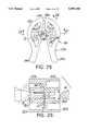
- the catheter cutteris generally comprised of a pair of members, each having a pair of hingedly connected tines, which members are clamped together about a pair of centrally disposed cutting blades.
- the catheter cutteris positioned at a proximal end of the catheter near the catheter connector and, in a manner similar to a wire cutter, hand pressure is applied to the tines of the catheter cutter to sever the catheter from the catheter hub without severing the wire guide.
- FIG. 1is an overall view of a dual-lumen biliary catheter of the present invention
- FIG. 2is a partially broken away, partial section view on an enlarged scale as compared to FIG. 1 of a dual-lumen biliary catheter of the present invention
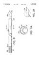
- FIG. 3is a side view, partly in section, of a dual-lumen biliary catheter body formed according to the present invention illustrating the distal tip illustrating the contrast stripes at the distal end of the catheter;
- FIG. 3Ais a section view illustrating the dual lumens of the biliary catheter of FIGS. 1-3 taken along line 3A--3A of FIG. 3;
- FIG. 3Bis a fragmentary side view of a dual lumen catheter having a balloon at the distal tip and having the cross-sectional configuration of FIG. 3A;
- FIG. 4illustrates a biliary catheter of the present invention through an endoscope accessory channel at the point of introduction into the common biliary duct;
- FIG. 5is an enlarged detailed view of a catheter of the present invention illustrating its exit from the distal tip of the accessory channel of the endoscope
- FIG. 6is a side elevational view of an alternative distal tip configuration for the biliary catheter of the present invention.
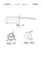
- FIG. 7illustrates the catheter and including a wire guide feed apparatus utilized with the present invention
- FIGS. 8 and 8Aillustrate views illustrating the unlocked and locked position of a wire guide locking mechanism used with the invention
- FIGS. 9A and 9Bare side and top views, respectively, of a catheter of the invention having a beveled tip and digitized markings;
- FIG. 10is an end view of the catheter of FIGS. 9A and 9B;
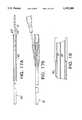
- FIGS. 11 and 12are side and end views of the distal tip section of a triple-lumen polypectomy catheter formed according to the invention.
- FIG. 12Ais a cross-sectional view of a modified form of the polypectomy catheter illustrated in FIGS. 11 and 12;
- FIGS. 13A and 13Billustrate the distal and proximal end sections, respectively, of a triple-lumen dilatation balloon catheter formed according to the invention
- FIG. 14is a detail view on an enlarged scale, in section, of a portion of the catheter of FIGS. 13A and 13B;
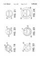
- FIG. 15is a sectional view on an enlarged scale taken on line 15--15 of FIG. 13A;
- FIG. 16is a sectional view on an enlarged scale taken on line 16--16 of FIG. 13A;
- FIGS. 17A and 17Billustrate the distal and proximal end sections of a multi-lumen catheter for placing a stent
- FIG. 18is a sectional view enlarged with respect to FIGS. 17A and 17B illustrating the distal portion of the catheter with the stent in position;
- FIG. 19is a cross-sectional view of a four-lumen catheter used for the purposes of cannulating the common bile duct and the pancreatic duct;
- FIG. 20is a cross-sectional view of a triple-lumen catheter in which a papillotome is accommodated for the purpose of tissue cutting as an aid to catheter insertion;
- FIG. 21illustrates a modified form of dual-lumen catheter useful for stone removal
- FIG. 22is a cross-sectional view of a triple-lumen catheter used for stone visualization and removal
- FIG. 23is a cross-sectional view of an alternative embodiment of a catheter used for the purposes explained with respect to FIGS. 13A-16;
- FIG. 25is a side elevational view of a catheter cutter in accordance with the present invention.
- FIG. 26is a sectional view depicting the catheter cutter assembly comprised of top and bottom components and centrally disposed cutting elements;
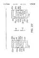
- FIG. 27is an exploded sectional view depicting the cutter top and bottom components and cutting blades prior to assembly
- FIG. 28is a side elevational view of the inside 35 of the top cutter component
- FIG. 29is a side elevational view of the inside of the bottom cutter component
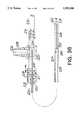
- FIG. 30is a side elevational view of a catheter and catheter connector of the type shown in FIG. 1;
- FIG. 31is a side elevational view of the catheter and catheter connector shown in FIG. 30 with the catheter cutter disposed so as to sever a portion of the catheter to remove the catheter connector from the catheter;
- FIG. 32is a side elevational view of the catheter being separated from the catheter connector
- FIG. 33is a side elevational view of a stent being threaded over the catheter with a guiding catheter placed behind the stent to advance the stent into position;
- FIG. 34is a top plan view of a needle-knife assembly where the needle-knife sheath, connecting tube and needle-knife are disposed within a multi-lumen catheter in accordance with the present invention and the needle-knife is retracted in a sheathed position;
- FIG. 35Ais a top plan view thereof with the needle-knife in a deployed position
- FIG. 35Bis a sectional detail view of the distal end of the catheter, catheter sheath and needle-knife in the deployed position.
- FIG. 36is a sectional view depicting details of the needle-knife actuator assembly, sheath and connecting tube.
- FIGS. 1-18Preferred embodiments of the improved catheters of the present invention are described with reference to FIGS. 1-18, wherein unless otherwise indicated, the same numbers are utilized to denote the same or equivalent parts.
- the present inventionwill be described in the context of its use in the cannulation and visualizing of the common biliary duct of a patient pursuant to an ERCP procedure.
- the present inventionis applicable to all ERCP procedures involving the cannulation and radiological visualization of the common biliary, pancreatic, common hepatic and cystic ducts and to related procedures, including those involving cholecystectomy, papillotomy, polypectomy and sphincteratomy, as well as biopsies, placement of stents and the use of cytology brushes.
- the catheter of the present inventioncomprises a cannula or tubular catheter body 12 having a proximal end 12a for connection to a branching connector 14 and a distal end 12b for insertion into the biliary duct of a patient.
- Tubular body 12has a substantially circular cross-sectional shape and a uniform outer diameter.
- Two independent lumensextend lengthwise thereof and exit through separate ports at the distal tip.
- the catheteris provided with a tip having a relatively sharp bevel, although unbevelled blunt tips and conically formed tips may sometimes be employed.
- the two lumen ports within the tipare oriented so that they face forwardly and substantially along the path of advance of the catheter.
- Tubular body 12in a preferred embodiment of a biliary catheter, has a length of approximately 200 cm. This length is sufficient to allow the catheter 10 to be inserted endotracheally into a patient via an endoscope and to reach within the biliary and pancreatic ducts located adjacent the patient's duodenum via an attached fiberscope during an ERCP procedure.
- branching means 14which couples the body 12 to wire guide feeding means 16 and contrast medium infusion means 18.
- branching means 14comprises a polymeric branching connector 15 which joins the wire guide feeding means 16 and contrast medium infusion means 18.
- the branching connector 15may include a connector 19 having an affixed apertured wing 20.
- the wire guide feeding means 16in a preferred embodiment, comprises a port having an eighteen gauge luer lock hub 17 which is affixed to the branching connector means 14.
- the wire guide feeding means 16is utilized to feed a wire guide 24 into and out of one lumen of the catheter 10.
- the wire guide 24may be threaded in one lumen of the catheter 10 prior to introduction of the catheter and wire guide into the endoscope.
- a wire guide utilized in the embodiment of FIGS. 1-3Apreferably has a diameter of about 0.035 inches. The use of a wire guide having this diameter permits the wire guide to be used for placing an indwelling stent, to be discussed below.
- the wire guide 24may optionally be coated with Teflon in order to add to its lubricity.
- the wire guide of the present inventionis preferably fed and withdrawn with the assistance of an auxiliary apparatus, such as the wire guide feed apparatus disclosed in U.S. Ser. No. 07/608,234 entitled "Hand Held Device For Feeding A Spring Wire Guide", filed Nov. 2, 1990, and now U.S Pat. No. 5,125,906 assigned to Arrow International Investment Corp., assignee of the present invention, and which is incorporated herein by reference.
- An overall view of such a device 27is illustrated in FIG. 7.
- Device 27includes an elongated coiled conduit 27a within which the wire guide 24 resides when not in use and a feed device 27b which allows for hand feed of the wire.
- the wire guide feed device 27is preferably affixed to the inlet hub of a wire clamping means, such as snap lock adapter 29 for locking the position of the wire.
- Snap lock adapter 29basically comprises a knob 29a which cams a tubular portion 29b radially inwardly to grip the wire guide upon relative movement of the parts toward one another.
- FIGS. 8 and 8Aillustrate the respective unlocked and locked positions of the adapter.
- the contrast medium infusion means 18in a preferred embodiment, preferably comprises a polymeric tube 26 which includes a twenty-gauge connector 28 secured to tube 26 at one end.
- the connector 28has a threaded outer surface 30 onto which a cap or stopper (not shown) may be affixed.
- the interior 28a of the connector 28is typically luer shaped and is designed to be coupled to a syringe containing radio-opaque contrast medium or dye.
- the contrast medium or dyeis injected down tube 26 and into a contrast medium lumen 34 of the catheter, as discussed below.
- the distal end 12b of the tube 12is shown in detail.
- the distal end of the catheterincludes a bevelled tip portion 12b and means 25 extending proximally of the tip portion for rendering sections of contrasting the outer distal surface of catheter radio-opaque.
- Contrast means 25facilitates the visual identification of the distal end of catheter 10 by the endoscope.
- means 25comprises a plurality of non-toxic ink stripes 25a, formed using an ink such as is sold under the specification 2920 by Gem Gravure of West Hanover, Mass. It is to be appreciated that contrast stripes 25a comprising other materials may be utilized in the catheter of the present invention.
- the entire catheter 10, or portions thereofmay be or applied with any acceptable contrast medium.
- the tip 12b of the cathetermay be calibrated as at 25a at predetermined intervals, such as 5 mm.
- the preferred catheter tip 12bis beveled to facilitate ease of insertion and passage.
- a relatively steep bevelhas been found to be an optimal configuration in that it is relatively easy and non-traumatic to position the catheter and affords reasonable resistance to bending and buckling.
- the lumens 32, 34 of a preferred form of dual-lumen catheter 10 of the present inventionare shown so as to detail their cross-sectional shape.
- the catheter 10includes wire guide lumen means 32 and contrast medium lumen means 34.
- the lumen means 32, 34extend the entire length of the catheter body, along parallel paths between the proximal end 12a and distal end 12b.
- distal end 12bis shown bevelled with the contrast medium lumen means 34 terminating just distally of the wire guide lumen means 32.
- lumens 32 and 34exit through ports in the distal tip which are oriented so that they face generally lengthwise or axially of the catheter. As illustrated in FIGS.
- the contrast lumen port 34is located in the perpendicular portion of the tip, whereas the major portion of the wire guide lumen port is in the beveled position.
- the port for lumen 32be within about one-quarter inch of the distal tip.
- the dye lumenis at the tip so as to eliminate interference with dye flow by the side walls of a narrow passageway and/or by the guide wire.
- wire guide lumen means 32is circular in cross-section and has a diameter of about 0.05 mm to allow passage of a 0.035 mm wire guide, a stent or other device of similar size.
- the top of wire guide lumen 32is defined by an arcuate septum 32a which defines the interior sidewall of the contrast medium lumen 34.
- contrast medium lumen 34is crescent shaped. While certain preferred embodiments of the present invention are described in the context of a biliary catheter having dual lumens, the present invention such catheters having more than two lumens.
- contrast medium lumen 34having a crescent shape as a means of maximizing lumen size within a relatively small diameter catheter body
- certain of the objectives of the inventionmay be achieved when the contrast medium lumen assumes one of a plurality of other geometric shapes.
- Catheters of the present inventionmay be constructed from extrudible polymers. Preferable proportions are about 18-22 wt. % barium sulfate, about 40 wt. % to about 60 wt % nylon 11 and about 20 wt. % to about 40 wt. % PEBA. A blend of 60 wt. % nylon 11, 20 wt. % PEBA and 20 wt. % barium sulfate is especially preferred. Nylon 11 sold under the trademark BESVOA and PEBA sold under the trademark Pebax are available from Elf Atochem, Philadelphia, Pa. The barium sulphate allows for easy visualization and catheter location under fluoroscopy and has been observed to increase stiffness. This blend is readily extruded into multi-lumen catheters having an o.d. ranging from 3.8 mm down to about 1.8 mm. Catheters formed from this blend have the requisite balance of torqueability, resistance to bunching and stretching and good flexibility.
- a further important feature of the present inventionis the addition of a hydrophilic coating on the outer surface of the catheter 10 and optionally within the wire guide lumen 32.
- the hydrophilic coatingwhen applied to the catheter, imparts suppleness and kink resistance to the catheter.
- the hydrophilic coatingfurther apparently reduces the hardness of the polyurethane or nylon.
- the hydrophilic coating of the preferred embodimentcomprises Methylene Chloride (MeCl), Polyethylene Oxide (PEO) and Tyrite 7617 Adhesive.
- the hydrophilic coatingis preferably applied to the catheter pursuant to the following process. Initially, 1400 ml of MeCl1 is poured into a container which is placed on stirrer plate. A stirring magnet is then dropped into the beaker, and the stirring plate is activated. Stirring is adjusted until a vortex forms. Next, 14.91 g. ⁇ 0.02 g. of PEO are slowly added to the stirring solution. The solution is stirred continuously for about 10 minutes in order to break up any lumps of PEO. Using a syringe, about 15.75 ml Tyrite 7617 adhesive is added to the stirring solution which is stirred for an additional five minutes. The stirred solution is then poured into a treatment tank.
- the catheter 10, with its end sealed offsis then dipped into the tank until the portion to be coated is immersed.
- the catheter 10is left in the tank for about 1 second, quickly retrieved and the excess solution allowed to drip into the tank.
- the catheteris then air dried for about 8 hours.
- the catheter 10 with hydrophilic coatingprovides a highly lubricated surface which is activated by the biliary fluids of the patient.
- the hydrophilic coatingmay also be activated by the gastric fluids which enter the endoscope.
- the hydrophilic coatingreduces the durometer of the catheter and imparts kink resistance and suppleness to the catheter.
- the coatinghas been found to yield a lower coefficient of friction than that of comparable Teflon catheters. While the present invention is being described in the context of a preferred hydrophilic coating, it is to be appreciated that other hydrophilic coatings may be utilized in the present invention. Examples of such hydrophilic coatings are found and described in U.S. Pat. No.
- hydrophilic coatingis Hydromer "Slippery When Wet” coating manufactured by Hydromer, Inc. of Whitehouse, N.J.
- the slippery coatingis not applied to the proximal end section of the catheter so as to facilitate manual manipulation thereof during catheter placement.
- the operation and use of the biliary catheter 10 as so far describedis now explained with reference to the Figures.
- the patientis sedated or, in rare situations, placed under general anesthesia.
- the wire guide advancer 27 of the type shown in FIG. 7the wire guide 24 is inserted through an endoscope and exits through the side of an attached fiberscope 36, the end of which is shown in FIG. 5 is situated in the patient's duodenum 38 as shown in FIG. 4.
- the catheter 10is then threaded over the spring wire guide 24 via spring wire guide lumen 32 or the catheter 10 having the wire guide 24 threaded therethrough is fed through the accessory channel 36 and both the catheter and wire guide are advanced into the common bile duct 40.
- a pre-filled syringe of radio-opaque dye or contrast mediumis attached to a connector 28.
- a sufficient amount of dye to fill the catheteris then injected into tube 26.
- a clamp or adhesive tapemay be used to lock the relative positions of the catheter and wire guide.
- An example of a clamp which achieves the functionis a clamp of the Series 340 clamps marketed by Halkey Medical of St. Russia, Fla.
- Contrast mediumis then injected into the contrast medium lumen 34 as shown in FIG. 3A which exits at distal end 12b and into the common biliary duct 40, thereby permitting X-ray or fluoroscopic visualization of the duct 40. Markings 25a facilitate precise adjustment of the catheter. If the position of the catheter needs to be adjusted, the wire guide 24 is advanced and the catheter 10 advanced accordingly. The catheter can be rapidly adjusted and contrast medium or dye can be repeatedly infused without the need for repeated insertion and removal of the wire guide 24.
- the present inventionthus provides for probing with the wire guide 24 via lumen 32 and the injection of contrast medium or dye via contrast medium lumen 34, and further probing and further injection of dye until a proper catheter position is achieved.
- the present inventioneliminates the time consuming step of removing the wire guide 24 prior to each change in catheter position and contrast medium infusion.
- the use of the catheter of the present inventioncan save over 20 minutes of time during a typical ERCP procedure.
- a laser fiber for biliary lithotripsycan be placed through one lumen with ongoing injection of contrast medium or fluid in the second lumen. Further, selective cannulation of the right and left hepatic ducts, cystic ducts or pancreas becomes more directed, safe and efficient.
- a particular feature of the present inventionis its adaptability for use in placing a stent around a biliary calculus 42 or cystic or pancreatic obstruction.
- surgeryis mandated.
- surgeryis often not always possible at the time of the ERCP procedure.
- a stentis typically placed within the common biliary or pancreatic duct around the calculus.
- the catheter 10is utilized in association with a wire guide 24 having a length greater than twice the length of the catheter 10, or over 400 cm in length.
- the wire guidemay be threaded with the catheter into the endoscope, as described above.
- the wire guide utilized in this embodimentshould preferably have a diameter of about 0.035 inches.
- the stentis tubular with a longitudinally extending slit which permits it to be fitted over the wire guide.
- the wire guideis advanced to a desired position within the common biliary duct and the catheter then advanced relative to the wire into a final position. Contrast medium or dye is infused, and the calculus 42 is located, as shown in FIG. 6. The catheter 10 is then removed from the endoscope.
- the catheter 10can be completely removed from the endoscope over the wire guide 24 without the need for withdrawing the wire guide.
- a stentmay be placed forward of the catheter over the wire guide. The catheter is utilized to push the stent into the endoscope, over the wire guide, into the common biliary duct and around the biliary calculus 42. When the stent is in position, the wire guide 24 is then removed along with the catheter.
- FIGS. 25-33there is depicted an illustrative embodiment of a catheter cutter 100 for severing a catheter 12 from a connector 14 of the type described above and illustrated in detail in FIG. 1, 9A, 9B and 10 to enable a second catheter 106 to be threaded over catheter 12 to advance a stent 108 into a desired position in a duct of a patient.
- catheter cutter 100is comprised of a top half 110a and a bottom half 110b which retain a pair of cutting blades 112 as described in more detail below.
- Top half 110aincludes a pair of tines 114a which are hingedly connected at area 116a to enable them to flex inwardly towards one another upon the application of hand pressure.
- the tines 114aeach define a semi-circular inner bore 118a bounded by projections 120a which engage corresponding shelves 121a to limit inward flex.
- the semi-circular inner bore 118a of each tinecommunicates with a second larger semi-circular bore 124a from which a plurality of projections 126a project radially inwards to engage the flanged hub portion 19 of the connector hub 14 as illustrated in FIGS. 26 and 31.
- a pair of outer bosses 130 and inner bosses 132project for engaging the cutting blades 112 as described below.
- a plurality of guideways 138are defined inwardly from inner end 128a to facilitate assembly as shown in FIG. 26 and described below.
- the bottom half 110bis of similar construction to top half 110a, and is principally comprised of a pair of tines 114b which are hingedly connected at area 116b.
- the tines 114aeach define a semi-circular inner bore 118b bounded by projections 120b which engage corresponding shelves 121b.
- the semi-circular inner bore 118b of each tinecommunicates with a second larger semi-circular bore 124b from which a plurality of projections 126b project radially inwards as described above.
- a pair of recesses 134are formed, in which cutting blades 112 are disposed.
- the cutting blades 112are fabricated from stainless steel and are preferably about 0.006 inches thick. The cutting blades are held in place by pressure between the top half 110a and the bottom half 110b when the components shown in the exploded view of FIG. 27 are assembled as depicted in FIG. 26.
- the bottom half 110bincludes a plurality of flexible fingers 136 which are received in guideways 138 of top half 110a in locking relation (FIG. 26).
- the catheter cutter 100may be used to sever a catheter 12 from a connector 14 to enable a stent 108 to be advanced over catheter 12 without having to remove the catheter 12.
- the use of this procedure for stent placement as described above with respect to placing a stent around the biliary calculus, cystic obstruction or pancreatic obstructionobviates the requirement for a wire guide having a length greater than twice the length of the catheter and the need to subsequently unthread the catheter over the wire guide 24.
- the methodentails the steps of placing the catheter cutter 12 over the flanged hub portion 19 of the connector 14 near the proximal end 12a of the catheter 12, applying hand pressure to the tines 114a and 114b until the catheter 12 is severed from the connector 14, stripping the connector 14 from the catheter 12, and then placing a stent 108 over the outer surface of the catheter and advancing the stent with a second catheter 106.
- a catheteras shown in FIGS. 3 and 3A, having a balloon adjacent its distal tip, as shown in FIG. 3B, may be used with a wire guide (not shown) having an iridium charge placed in its distal tip so as to dispose iridium for treatment in the biliary tract.
- the wire employedis preferably 0.035 inches in thickness and is passed through a nasal passage using an endoscope.
- the endoscopeis removed and the catheter is advanced over the wire guide using lumen 32 as the wire guide lumen adapted to be passed through round lumen 32 having a diameter of 0.040 inches.
- Lumen 34serves as the inflation lumen and exits in a radial port for inflation of the balloon.
- the overall diameter of the catheteris 2.8 mm.
- Catheters having the cross-section of FIG. 3are also useful for tissue sampling with a brush.
- lumen 32preferably has a diameter of about 0.040 inches.
- Lumen 34is utilized for a saline solution for the purpose of cleansing the tissue to be sampled prior to obtaining the sample with the brush.
- a triple-lumen catheter used in the practice of polypectomyis disclosed in FIGS. 11 and 12.
- the catheter illustrated in FIGS. 11 and 12has a first lumen 48 dimensioned to pass a polypectomy snare, a second lumen 49 through which an injection medium will be passed and a retrieval lumen 50 for passage of a basket or other retrieval device.
- Lumen 49 or lumen 50may be used to pass a flexible plastic or stainless steel needle for injecting a polyp once it is visualized to further assist the physician in excising the polyp with a snare.
- the snareis a device which uses radio frequency energy to cauterize the root of the polyp and the energy so used exits through a plate in which the patient is seated.
- a net, basket or other retrieval device of known constructionis passed through lumen 49 for grasping and retrieval of the polyp through the lumen. If a large polyp is to be removed, the catheter itself is removed at this point.
- the snare lumenhas a diameter of 0.5 mm, whereas the lumens 49 and 50 have diameters of 0.4 mm.
- Lumen 48exits through the bevelled portion of the distal tip, whereas lumens 49 and 50 exit through the portion disposed perpendicular to the long axis of the catheter.
- the dual-lumen catheter configuration of FIG. 12Amay be satisfactory for the practice of polypectomy.
- the catheter configuration of FIG. 12Ais provided with a lumen 48a of about 0.050 inches in diameter for passage of the snare and a lumen 49a of about 0.040 inches in diameter for the injection needle device. Retrieval is effected by withdrawal of the catheter with the embodiment of FIG. 12A.
- the catheter illustrated in FIG. 12Apreferably has an outside diameter of about 2.8 mm.
- FIGS. 13A-16Still another embodiment of the invention, as illustrated in FIGS. 13A-16, is a triple-lumen catheter having a dilatation balloon 52 which may be used, for example, to facilitate removal of gall stones by the dilation of a restricted portion of the biliary tract.
- the catheter of FIGS. 13A-16has a main body portion 53 of a first uniform outer diameter and a distal tip portion 54 of a smaller uniform outer diameter.
- the distal tiphas a bevelled configuration similar to the tip of the embodiment of FIGS. 1-3.
- the catheter of FIGS. 13A-16has a first lumen 55 which extends lengthwise thereof from a connector 56 to an exit port at the distal tip in the manner illustrated in FIG. 10.
- Lumen 55is preferably sized to permit the passage of a 0.035 inch guide wire.
- a second crescent shaped lumen 57, as illustrated in FIGS. 15 and 16,also exits in a port at the distal tip and provides for the injection of tracer dye.
- the catheteris also provided with a third lumen 58 which exits in a shoulder 59 separating the larger diameter main body portion 53 from the smaller diameter tip portion 54.
- Lumen 58is provided for the delivery of an inflation medium for inflating the balloon 52.
- the inflation medium employedis desirably an incompressible fluid and is typically a saline solution.
- the fluidmay include a tracer dye to permit visualization of the balloon by fluoroscopy.
- the catheter of FIGS. 13A-16has a maximum diameter of 2.8 mm to allow for passage through the accessory channel of an endoscope and a diameter of approximately 1.8 mm in the distal tip portion. The use of a smaller diameter distal tip portion facilitates passage into more remote portions of the biliary tract and also provides room for packing the uninflated balloon so that it does not project appreciably beyond the surface of the large diameter catheter body portion.
- Another catheter configuration for use with a dilation balloon 52is shown in FIG. 23 and described below.
- the catheter of FIGS. 13A-16is advanced utilizing the wire guide, as described above, until the desired position is reached, utilizing a tracer dye and fluoroscopy to assist in the guidance of the catheter to the desired location.
- Balloon 52is inflated when the event a stricture in the biliary duct is encountered. Once the duct is dilated, stones encountered may, in many cases, dislodge and begin to remove themselves naturally, but if need be, a stent may be inserted to maintain patency of the duct to encourage the passage of the stone or the guide wire may be removed and an extractor device may be employed utilizing lumen 55.
- FIGS. 17A-18illustrate a catheter having utility for the placement of a stent in the biliary tract.
- the catheter of FIGS. 17A-18is similar in structure to the catheter of FIGS. 13A-16 in that it has a main body portion 60 of a first diameter and a distal tip portion 61 of a second similar diameter on which a stent 62 is supported.
- the distal portion 61has an outer diameter of 1.8 mm which is suitable for supporting a 10 French tubular stent formed of a biologically inert material, such as polyurethane. As seen in FIG.
- main body portion 60has an outer diameter of 2.8 mm for passage through a 3.2 mm endoscope accessory channel.
- the outer diameter of stent 62is approximately 3 mm.
- the catheter of FIGS. 17A-18is provided with two independent and continuous lumens 55 and 57 preferably having the configurations of the lumens in FIG. 16.
- Lumen 55is dimensioned to accept a 0.035 wire guide which exits at the distal tip.
- the crescent shaped lumen 57provides for the injection of tracer dye for use in visualization of the passage and location of the stricture where the stent is intended to be placed.
- the catheteris advanced over the wire guide using the tracer dye to assist in placing it.
- the catheter and wire guideare withdrawn leaving the stent in place.
- stent 62is provided with barbs 63 which hold the stent in position as the catheter is withdrawn. The barbs are yieldable upon application of a predetermined force by a retrieval device when it is desired to remove the stent.
- An advantage of the embodiment of FIGS. 17A-18is that the relatively small diameter distal portion relatively easily negotiates restricted portions of the duct. The procedure is facilitated by maintaining the wire guide within the catheter to impart stiffness to the catheter and resistance to kinking.
- Catheters having three or more lumensallow for the performance of other procedures in conjunction with ERCP or the use of a lighting device while allowing the wire guide to remain in place.
- Triple-lumen catheters having outside diameters ranging from 3.8 mm down to about 1.8 mmmay be extruded utilizing the resin blends described above with three lumens having inside diameters of 0.5 mm with a minimal wall thickness of 0.005 inches.
- One such lumenwill accommodate a 0.018 mm wire guide, while the second lumen is reserved for infusion of contrast medium, and a third such lumen is reserved for additional instruments, such as a papillotome or sphincteratome, a snare, a basket and other accessories, such as forceps, stone extractor, biopsy cutters or direct visualization lighting devices. Additionally, a lumen may be provided which exits radially at a location spaced adjacent the distal tip for inflation of a dilation balloon used for dilating the tract for removing bile stones or a previously introduced stent. Catheters formed in accordance with the invention are useful for the endoscopic examination and treatment of other parts of the gastrointestinal system as well. Multi-lumen catheters can be provided with outer diameters of 3.8, 2.8 and 1.8 mm which allow for use with standard endoscopes having channels with internal diameters of 4.2, 3.2 and 2.2 mm, respectively.
- a catheter having three or more lumensmay be maintained within its lumen while performing a procedure involving advancement of a device, such as a cytology brush, papillotome or an optical visualizer, allowing a third lumen to be reserved for the injection of dye.
- a devicesuch as a cytology brush, papillotome or an optical visualizer.
- the presence of the wire guideserves to prevent kinking and collapse of all lumens, thus allowing for unimpeded advancement of the device employed, dye injection and/or aspiration of bile for laboratory analysis through a lumen not contaminated with dye.
- the wire guidealso facilitates switching from one device to another.
- a fourth lumenmay be advantageously reserved for injection of saline solution to clear the area being visualized prior to use of the device.
- FIG. 19is a cross-section of a multi-lumen catheter utilized for disposing two 0.035 inch wire guides simultaneously, one within the pancreatic duct and one through the cystic duct through lumens 70 and 71, utilizing contrast medium injected through lumens 72 and 73.
- the catheter of FIG. 19is withdrawn and individual catheters advanced over the selected guide wire for catheterization of either the pancreatic or cystic duct.
- the catheter of FIG. 19preferably has an outer diameter of about 2.8 mm.
- the catheter of FIG. 19is of advantage when an uncertainty exists as to the extent and location of patient stress.
- FIG. 20illustrates a cross-section of a catheter with which a papillotome is used for tissue cutting as an aid for catheter insertion.
- circular lumen 74is reserved for a papillotome which is preferably permanently mounted in the lumen.
- Placement of the catheter of FIG. 20involves use of additional lumen 75 for a wire guide and additional lumen 76 for contrast medium in the manner described above with respect to FIGS. 1-12.
- the catheter of FIG. 20preferably has an outside diameter of about 2.8 mm.
- FIG. 21is a cross-section of a catheter useful in procedures for stone removal.
- Lumen 78(upper) is used for the passage alternatively of a guide wire or a fiber optic device for visualization of stones.
- Lumen 79is reserved for passage of a stone basket.
- the catheter of FIG. 21may be equipped with a dilatation balloon adjacent its distal tip which is inflated with an incompressible medium. After placement of the distal tip, the balloon is inflated to dilate the duct to effect dislodgment of the stone.
- a catheter so constructedwill have an outside diameter of approximately 2.8 mm.
- the guide wiremay be removed and replaced with the optical device for visualization of the stone removed by the basket or by dislodgment with the balloon.
- An alternative use of a catheter having the configuration of FIG. 21includes use of a vacuum assist for stone removal by application of a vacuum to one of the lumens while reserving the other either for a stone retrieval basket or as the inflation lumen for the balloon.
- the catheterpreferably has an outside diameter of about 3.8 mm.
- FIG. 22depicts an alternative form of catheter used for visualization and removal of gall stones.
- lumens 82, 83are used for injection of contrast medium and for a guide wire respectively.
- Lumen 84is reserved for a basket for the removal of stones.
- FIG. 23is an end view of triple-lumen catheter having an alternative configuration to the one illustrated in FIG. 15, for use with the dilation balloon 52 in which the inflation lumen, shown at 86, is an annular lumen.
- the annular inflation lumen 86facilitates more rapid inflation and deflation of the balloon 52 because of the greater volume of air which may be passed therethrough as compared to the catheter configuration depicted in FIG. 15.
- the catheteris provided with a circular lumen 87 for a 0.035 inch wire guide and a crescent-shaped lumen 88 for injection of contrast medium.
- the catheter of FIG. 23preferably has a 2.8 mm outside diameter and is in other respects substantially the same as the embodiment illustrated in FIGS. 13A-16.
- FIG. 24illustrates an end view of a modified version of the catheter of FIGS. 17 and 18.
- the catheter depictedhas a wire guide lumen 90, a retrieval lumen 92 for a basket or snare and a dye lumen 94, all extending through the reduced diameter distal tip portion. Except for the inflation lumens, the lumens in FIGS. 19-24 extend continuously and independently and exit through axially facing ports.
- the catheter of FIG. 24has a maximum outside diameter of about 3.8 mm.
- the reduced diameter distal portionhas a diameter of about 2.8 mm which allows for support of a 7 French stent 95 having its circumference flush with the circumference of the remainder of the catheter.
- the snareis utilized to grasp its proximal end.
- the stentis withdrawn by withdrawing the snare and, if necessary, the catheter until the stent is within the large intestine where it may be released.
- the guide wireis used to locate the tip of the catheter at the desired location with the biliary or cystic duct.
- the catheteris withdrawn with the stent remaining in place and the catheter then removed further until it is within the intestine.
- the snare or basketis then used to pick up the old stent and the endoscope and catheter are then withdrawn from the body.
- FIGS. 34-36there is depicted a needle-knife assembly 200 adapted for use with the multi-lumen catheter 12 shown in FIGS. 1, 9A, 9B and 10.
- the needle-knife assembly 200is principally comprised of a deployment mechanism 202, and an elongated sheath 204 having an elongated connecting tube 205 and needle-knife 206 disposed therein.
- the deployment mechanism 202includes a body 208 having a pair of rails 210 which define a centrally disposed slot 212.
- Body 208includes a first end 214 in which a thumb ring 216 is disposed, and a second end 218 having an end portion 211 at which a fitting 220 is located for receiving the sheath 204 and connecting tube 205 as described below.
- a sliding member 222is slidably connected to the body 208.
- the sliding member 222includes a pair of opposed finger rings 224 which enable a user to grasp the same with the forefinger and index finger.
- the sliding member 222may be advanced towards the second end 218 of the body 208 to deploy the needle-knife 206, and retracted towards the first end 214 and against stops 221 to withdraw the needle-knife 206 into the sheath 204 as described below.
- a slidable stop 209is disposed over the end portion 211 as shown. The sliding stop 209 may be moved towards and away from the second end 218 to limit the travel of the sliding member 222 to enable adjustable positioning of a distal end 213 of the needle-knife 206 relative to a distal end 215 of the sheath 204 by a variable distance V d between a fully deployed position (FIG.
- the sliding member 222has an internally disposed brass insert 224 which electrically communicates with a brass binding post 226 for making an electrical connection to a power source (not shown) to provide a cutting/coagulating current as is well known in the art.
- the binding post 226is situated within a connector cap 228 integral with sliding member 222.
- the elongated connecting tube 205is attached to and electrically communicates with the insert 224.
- the connecting tube 205is fabricated from stainless steel and extends through the fitting 220 in the second end 218 of the mechanism body 208 and terminates in a distal end 230.
- the connecting tube 205has a hollow bore (not shown) into which the needle-knife 206 is partially disposed near distal end 230.
- the connecting tube 205is then crimped over the needle-knife 206 at location 234 as shown in FIG. 36.
- the fitting 220tightly receives the elongated tubular sheath 204 and provides strain relief therefor.
- the sheath 204is made from polyimide material with a Teflon coating. This enables fabrication of a sheath 204 with an outer diameter as small as approximately 0.035 inches, to enable advancing the same through one lumen of the dual lumen catheter 12 used in an ERCP procedure in accordance with the present invention.
- the use of polyimide materialprovides good kink resistance, even if the sheath is fabricated with a very thin wall thickness, and the Teflon coating provides a smooth surface to enable the sheath 204 to be easily inserted and removed from the catheter 12.
- FIG. 35Bshows the orientation of the connecting tube 204 disposed within the catheter 12, where the distal end 232 of the sheath 204 extends a nominal distance from the distal end 12b of the catheter 12.
- the needle-knife 206has a diameter of approximately 0.006 inches, and is fabricated from a "memory" metal alloy such as Nitonil.
- a "memory" metal alloysuch as Nitonil.
- memory metalsundergo a crystalline phase change and thermoelastically deform when heated and cooled. These crystal phase changes between what are known as high temperature Austenite and low temperature Martensite, enable a component made from such material to contract when heated, and to return to its original configuration when cooled.
- the stress-strain behavior of a memory metal alloymakes the material much easier to deform when cooled (Martensite) than when at an elevated temperature (Austenite).
- the use of this materialis advantageous since the needle-knife 206 is very thin and susceptible to deformation during the cutting procedure.
- the memory materialhelps it return to its original orientation if deformed by stress during the cutting procedure.
- the needle-knife 204is heated by applying the cutting/coagulating current, the crystalline transformation to Austenite makes it much more difficult to deform. If a sufficient force is then applied to the needle-knife 206 during the procedure, the material can strain to relieve the applied stress as it transforms back to Martensite, and once the stress is reduced, it will unstrain and revert back to Austenite. Finally, after the applied current is removed, the resulting cooling of the needle-knife material and associated crystal phase change to Martensite makes it more flexible.
- the needle-knife 206is disposed so as to remain in a sheathed position within sheath 204 with respect to the distal end 232 thereof.
- the sheath 204is inserted through lumen 32 of catheter 12 so that the distal end 232 of the sheath protrudes slightly beyond the distal end 12b of the catheter 12.
- the catheter assembly(of the type shown in FIG. 1) is attached to the deployment mechanism 202 by threading the luer lock hub 17 of the connector 14 into the insert 220 at the second end 218 of the deployment mechanism 202.
- the needle-knife assembly 200is pre-loaded in the catheter 12. This facilitates the use of the needle-knife assembly in a typical ERCP procedure using a multi-lumen catheter.
- the physicianadvances the catheter 12 through an endoscope (as shown in FIG. 4) and into the patient's duodenum proximal to the entrance to the common bile duct 40, typically into or just above the papillary orifice.
- the physicianadvances the sliding member 222 towards the second end 218 of the deployment mechanism 202 to cause the needle-knife 206 to extend from the distal end of the sheath 204 as shown in FIGS.
- the slidable stop 209may be moved over the end portion 211 to custom position the needle-knife 206 with the distal end 213 thereof at a desired distance V d relative to the distal end 215 of the sheath 204 prior to moving the sliding member 222 towards the second end 218.
- the physicianapplies an appropriate amount of cutting/coagulating current to the needle-knife 206 through the binding post 226, and manipulates the needle-knife by using the elevator and/or positioning controls of the endoscope to incise tissue. Typically, a 3-5 millimeter across by 2-4 millimeter deep incision into the papilla is sufficient.
- the needle-knife 206is then retracted into the distal end 232 of the sheath 204 by moving the sliding member 222 rearwardly towards the first end 214 and against the stops 221 of the deployment mechanism 202. This enables the physician to insert the catheter 12 into the common bile duct with less effort. Once access is gained to the common bile duct, the physician can then cannulate and visualize the same in accordance with the ERCP procedure described in the foregoing.
- the sheath 204 and needle-knife 206can be left within the first lumen 32 of the catheter 12 to function as a stiffening element to enable advancing the catheter into the common bile duct 40 (see FIG.
- the sheath 204 and needle-knife 206may be withdrawn from the catheter 12, and a wire guide 24 then inserted in its place by simply unthreading the luer lock hub 17 from deployment mechanism 202 and attaching a wire guide feeding apparatus 27 as shown in FIG. 7 and described above.
- the common bile duct 40can then be visualized by infusing a contrast medium through lumen 34.
- the wire guide 24may be advanced along the duct and the catheter 12 then repositioned by advancing the catheter 12 over the wire guide to the appropriate location, and the infusion procedure may be repeated.
- This methodsaves a considerable amount of time over prior art procedures where cutting instruments had to be removed prior to infusing the contrast medium.
- the physiciancan perform several diagnostic and therapeutic procedures with only one cannulation of the common bile duct.
Landscapes
- Health & Medical Sciences (AREA)
- Life Sciences & Earth Sciences (AREA)
- Engineering & Computer Science (AREA)
- Veterinary Medicine (AREA)
- General Health & Medical Sciences (AREA)
- Surgery (AREA)
- Biomedical Technology (AREA)
- Heart & Thoracic Surgery (AREA)
- Public Health (AREA)
- Animal Behavior & Ethology (AREA)
- Physics & Mathematics (AREA)
- Otolaryngology (AREA)
- Biophysics (AREA)
- Cardiology (AREA)
- Pulmonology (AREA)
- Plasma & Fusion (AREA)
- Nuclear Medicine, Radiotherapy & Molecular Imaging (AREA)
- Hematology (AREA)
- Anesthesiology (AREA)
- Medical Informatics (AREA)
- Molecular Biology (AREA)
- Media Introduction/Drainage Providing Device (AREA)
- Surgical Instruments (AREA)
- Laser Surgery Devices (AREA)
Abstract
Description
Claims (7)
Priority Applications (7)
| Application Number | Priority Date | Filing Date | Title |
|---|---|---|---|
| US08/440,562US5599300A (en) | 1992-05-11 | 1995-05-12 | Method for electrosurgically obtaining access to the biliary tree with an adjustably positionable needle-knife |
| PCT/US1996/006778WO1996035470A1 (en) | 1995-05-12 | 1996-05-13 | Method and apparatus for electrosurgically obtaining access to the biliary tree with an adjustably positionable needle-knife |
| CA002220683ACA2220683C (en) | 1995-05-12 | 1996-05-13 | Method and apparatus for electrosurgically obtaining access to the biliary tree with an adjustably positionable needle-knife |
| JP53431896AJP3753738B2 (en) | 1995-05-12 | 1996-05-13 | Device for electrosurgical access to the dendritic branch of the gallbladder with an adjustable needle scalpel |
| BR9608135-0ABR9608135A (en) | 1995-05-12 | 1996-05-13 | Method and apparatus for electrosurgically obtaining access to a biliary tree with an adjustable needle knife. |
| AU58576/96AAU5857696A (en) | 1995-05-12 | 1996-05-13 | Method and apparatus for electrosurgically obtaining access to the biliary tree with an adjustably positionable needle-k nife |
| US08/794,162US5843091A (en) | 1995-05-12 | 1997-02-03 | Extension regulator for catheter carried medical instruments |
Applications Claiming Priority (5)
| Application Number | Priority Date | Filing Date | Title |
|---|---|---|---|
| US88084092A | 1992-05-11 | 1992-05-11 | |
| US08/060,434US5397302A (en) | 1992-05-11 | 1993-05-11 | Method of using a dual lumen biliary catheter |
| US08/189,317US5599299A (en) | 1992-05-11 | 1994-01-31 | Multi-lumen endoscopic catheter |
| US08/332,836US5536248A (en) | 1992-05-11 | 1994-11-01 | Method and apparatus for electrosurgically obtaining access to the biliary tree and placing a stent therein |
| US08/440,562US5599300A (en) | 1992-05-11 | 1995-05-12 | Method for electrosurgically obtaining access to the biliary tree with an adjustably positionable needle-knife |
Related Parent Applications (1)
| Application Number | Title | Priority Date | Filing Date |
|---|---|---|---|
| US08/332,836Continuation-In-PartUS5536248A (en) | 1992-05-11 | 1994-11-01 | Method and apparatus for electrosurgically obtaining access to the biliary tree and placing a stent therein |
Related Child Applications (1)
| Application Number | Title | Priority Date | Filing Date |
|---|---|---|---|
| US08/794,162Continuation-In-PartUS5843091A (en) | 1995-05-12 | 1997-02-03 | Extension regulator for catheter carried medical instruments |
Publications (1)
| Publication Number | Publication Date |
|---|---|
| US5599300Atrue US5599300A (en) | 1997-02-04 |
Family
ID=23749254
Family Applications (2)
| Application Number | Title | Priority Date | Filing Date |
|---|---|---|---|
| US08/440,562Expired - LifetimeUS5599300A (en) | 1992-05-11 | 1995-05-12 | Method for electrosurgically obtaining access to the biliary tree with an adjustably positionable needle-knife |
| US08/794,162Expired - LifetimeUS5843091A (en) | 1995-05-12 | 1997-02-03 | Extension regulator for catheter carried medical instruments |
Family Applications After (1)
| Application Number | Title | Priority Date | Filing Date |
|---|---|---|---|
| US08/794,162Expired - LifetimeUS5843091A (en) | 1995-05-12 | 1997-02-03 | Extension regulator for catheter carried medical instruments |
Country Status (6)
| Country | Link |
|---|---|
| US (2) | US5599300A (en) |
| JP (1) | JP3753738B2 (en) |
| AU (1) | AU5857696A (en) |
| BR (1) | BR9608135A (en) |
| CA (1) | CA2220683C (en) |
| WO (1) | WO1996035470A1 (en) |
Cited By (106)
| Publication number | Priority date | Publication date | Assignee | Title |
|---|---|---|---|---|
| WO1999017669A1 (en) | 1997-10-03 | 1999-04-15 | Boston Scientific Corporation | Device and method for facilitating access to a duct within the human body |
| US5921971A (en)* | 1996-09-13 | 1999-07-13 | Boston Scientific Corporation | Single operator exchange biliary catheter |
| US6007522A (en)* | 1996-09-13 | 1999-12-28 | Boston Scientific Corporation | Single operator exchange biliary catheter |
| US6096009A (en)* | 1996-09-13 | 2000-08-01 | Boston Scientific Corporation | Guidewire and catheter locking device and method |
| WO2000062845A1 (en)* | 1999-04-16 | 2000-10-26 | Heartport, Inc. | Device and methods for cannulating a blood vessel |
| US6159225A (en)* | 1995-10-13 | 2000-12-12 | Transvascular, Inc. | Device for interstitial transvascular intervention and revascularization |
| US6190353B1 (en) | 1995-10-13 | 2001-02-20 | Transvascular, Inc. | Methods and apparatus for bypassing arterial obstructions and/or performing other transvascular procedures |
| US6283951B1 (en) | 1996-10-11 | 2001-09-04 | Transvascular, Inc. | Systems and methods for delivering drugs to selected locations within the body |
| US6302875B1 (en) | 1996-10-11 | 2001-10-16 | Transvascular, Inc. | Catheters and related devices for forming passageways between blood vessels or other anatomical structures |
| US20010049497A1 (en)* | 2000-03-24 | 2001-12-06 | Kalloo Anthony Nicolas | Methods and devices for diagnostic and therapeutic interventions in the peritoneal cavity |
| US6346093B1 (en) | 1996-09-13 | 2002-02-12 | Scimed Life Systems, Inc. | Single operator exchange biliary catheter with common distal lumen |
| US6379319B1 (en) | 1996-10-11 | 2002-04-30 | Transvascular, Inc. | Systems and methods for directing and snaring guidewires |
| US6443924B1 (en) | 1994-05-13 | 2002-09-03 | Scimed Life Systems, Inc. | Apparatus for performing diagnostic and therapeutic modalities in the biliary tree |
| US20020193873A1 (en)* | 2001-02-26 | 2002-12-19 | Brucker Gregory G. | Bifurcated stent and delivery system |
| US6520951B1 (en) | 1996-09-13 | 2003-02-18 | Scimed Life Systems, Inc. | Rapid exchange catheter with detachable hood |
| US6533782B2 (en) | 2000-05-18 | 2003-03-18 | Wilson-Cook Medical Incorporated | Medical device with improved wire guide access |
| US20030060842A1 (en)* | 2001-09-27 | 2003-03-27 | Yem Chin | Method and apparatus for measuring and controlling blade depth of a tissue cutting apparatus in an endoscopic catheter |
| US20030097169A1 (en)* | 2001-02-26 | 2003-05-22 | Brucker Gregory G. | Bifurcated stent and delivery system |
| US6572629B2 (en) | 2000-08-17 | 2003-06-03 | Johns Hopkins University | Gastric reduction endoscopy |
| US6579300B2 (en) | 2001-01-18 | 2003-06-17 | Scimed Life Systems, Inc. | Steerable sphincterotome and methods for cannulation, papillotomy and sphincterotomy |
| US6582401B1 (en) | 1996-09-13 | 2003-06-24 | Scimed Life Sytems, Inc. | Multi-size convertible catheter |
| US6602250B2 (en) | 2000-01-31 | 2003-08-05 | Wilson-Cook Medical Incorporated | Echogenic wire knife |
| US6606515B1 (en) | 1996-09-13 | 2003-08-12 | Scimed Life Systems, Inc. | Guide wire insertion and re-insertion tools and methods of use |
| US6613002B1 (en) | 1999-06-05 | 2003-09-02 | Wilson-Cook Medical Incorporated | System of indicia for a medical device |
| US6669643B1 (en) | 1998-04-13 | 2003-12-30 | Theodore J. Dubinsky | Method and apparatus for sonographic examination, biopsy, and excision |
| US6676659B2 (en)* | 2000-08-14 | 2004-01-13 | Scimed Life Systems, Inc. | Steerable sphincterotome and methods for cannulation, papillotomy and sphincterotomy |
| US6695877B2 (en) | 2001-02-26 | 2004-02-24 | Scimed Life Systems | Bifurcated stent |
| US20040092956A1 (en)* | 2000-11-03 | 2004-05-13 | John Liddicoat | Catheter for removal of solids from surgical drains |
| US6764484B2 (en) | 2001-03-30 | 2004-07-20 | Scimed Life Systems, Inc. | C-channel to o-channel converter for a single operator exchange biliary catheter |
| US6770066B1 (en) | 1992-05-11 | 2004-08-03 | Ballard Medical Products | Multi-lumen endoscopic catheter |
| US6827718B2 (en) | 2001-08-14 | 2004-12-07 | Scimed Life Systems, Inc. | Method of and apparatus for positioning and maintaining the position of endoscopic instruments |
| US20050059890A1 (en)* | 2003-07-31 | 2005-03-17 | Wislon-Cook Medical Inc. | System and method for introducing multiple medical devices |
| US20050143770A1 (en)* | 2003-07-31 | 2005-06-30 | Carter Matthew P. | Distal wire stop |
| US20050148820A1 (en)* | 2003-02-19 | 2005-07-07 | Boston Scientific Scimed, Inc. | Guidewire locking device and method |
| US20050165412A1 (en)* | 2001-05-18 | 2005-07-28 | U.S. Endoscopy Group. Inc. | Retrieval device |
| US20060015040A1 (en)* | 2003-03-25 | 2006-01-19 | Olympus Corporation | Guide wire |
| US20060030864A1 (en)* | 2003-07-31 | 2006-02-09 | Wilson-Cook Medical Inc. | Catheter with splittable wall shaft and peel tool |
| US20060111704A1 (en)* | 2004-11-22 | 2006-05-25 | Rox Medical, Inc. | Devices, systems, and methods for energy assisted arterio-venous fistula creation |
| US20060149165A1 (en)* | 2004-12-15 | 2006-07-06 | Wilson-Cook Medical Inc. | Minimally invasive medical device with helical pattern for indicating distance of movement |
| US20060173438A1 (en)* | 2005-01-28 | 2006-08-03 | Boston Scientific Scimed, Inc. | Universal utility board for use with medical devices and methods of use |
| US20060241661A1 (en)* | 2002-08-29 | 2006-10-26 | Boston Scientific Scimed | Devices and methods for fastening tissue layers |
| US20060264988A1 (en)* | 2003-05-02 | 2006-11-23 | Metolius Biomedical, Llc | Body-space drainage-tube debris removal |
| US20070005122A1 (en)* | 2004-09-24 | 2007-01-04 | Olympus Corporation | Treatment instrument installation member, stent delivery catheter and conduit system |
| US20070014945A1 (en)* | 2005-07-12 | 2007-01-18 | Boston Scientific Scimed, Inc. | Guidewire with varied lubricity |
| US7214229B2 (en) | 1999-03-18 | 2007-05-08 | Fossa Medical, Inc. | Radially expanding stents |
| US20070135904A1 (en)* | 2005-12-14 | 2007-06-14 | Tracee Eidenschink | Telescoping bifurcated stent |
| US20070135903A1 (en)* | 2005-12-14 | 2007-06-14 | Daniel Gregorich | Connectors for bifurcated stent |
| US20070208414A1 (en)* | 2006-03-06 | 2007-09-06 | Shawn Sorenson | Tapered strength rings on a bifurcated stent petal |
| US20070233233A1 (en)* | 2006-03-31 | 2007-10-04 | Boston Scientific Scimed, Inc | Tethered expansion columns for controlled stent expansion |
| EP1854500A1 (en)* | 2006-05-09 | 2007-11-14 | Olympus Medical Systems Corp. | Treatment tool inserting/withdrawing auxiliary device |
| US20080058789A1 (en)* | 2006-09-06 | 2008-03-06 | Cardiofirst | Guidance system used in treating chronic occlusion |
| US20080103481A1 (en)* | 2006-09-29 | 2008-05-01 | Pluromed, Inc. | Methods for Preventing Retropulsion of Concretions and Fragments During Lithotripsy |
| US20080109022A1 (en)* | 2006-11-08 | 2008-05-08 | Boston Scientific Scimed, Inc. | Sphincterotome with stiffening member |
| US20080167628A1 (en)* | 2007-01-05 | 2008-07-10 | Boston Scientific Scimed, Inc. | Stent delivery system |
| US20090005754A1 (en)* | 2007-06-29 | 2009-01-01 | Wilson-Cook Medical Inc. | Distal wire stop having adjustable handle |
| US20090018604A1 (en)* | 2007-07-11 | 2009-01-15 | Vladimir Mitelberg | Methods And Systems for Submucosal Implantation of a Device For Diagnosis and Treatment with a Therapeutic Agent |
| US20090018603A1 (en)* | 2007-07-11 | 2009-01-15 | Vladimir Mitelberg | Methods and Systems for Submucosal Implantation of a Device for Diagnosis and Treatment of a Body |
| US20090018602A1 (en)* | 2007-07-11 | 2009-01-15 | Vladimir Mitelberg | Methods And Systems For Performing Submucosal Medical Procedures |
| US20090062769A1 (en)* | 2007-04-13 | 2009-03-05 | Boston Scientific Scimed, Inc. | Rapid exchange catheter converter |
| US20090264833A1 (en)* | 2008-01-25 | 2009-10-22 | Clear Catheter Systems, Llc | Methods and Devices to Clear Obstructions from Medical Tubes |
| US7645254B2 (en) | 1994-05-13 | 2010-01-12 | Boston Scientific Scimed, Inc. | Apparatus for performing diagnostic and therapeutic modalities in the biliary tree |
| US7674283B2 (en) | 1999-03-18 | 2010-03-09 | Fossa Medical, Inc. | Radially expandable stents |
| US20100081878A1 (en)* | 2008-05-19 | 2010-04-01 | Boston Scientific Scimed, Inc. | Integrated Locking Device With Active Sealing |
| US20100121357A1 (en)* | 1995-10-13 | 2010-05-13 | Medtronic Vascular, Inc. | Tissue Penetrating Catheters having Integral Imaging Transducers and Their Methods of Use |
| US20100130835A1 (en)* | 2008-09-30 | 2010-05-27 | Rox Medical, Inc. | Methods for screening and treating patients with compromised cardiopulmonary function |
| US20100217151A1 (en)* | 2007-07-11 | 2010-08-26 | Zach Gostout | Methods and Systems for Performing Submucosal Medical Procedures |
| US7811250B1 (en) | 2000-02-04 | 2010-10-12 | Boston Scientific Scimed, Inc. | Fluid injectable single operator exchange catheters and methods of use |
| US20100300449A1 (en)* | 2009-05-28 | 2010-12-02 | Chan Sam C | Position Indicator for Tracheostomy Tube |
| US20110040286A1 (en)* | 2008-01-25 | 2011-02-17 | Clear Catheter Systems, Inc. | Methods and devices to clear obstructions from medical tubes |
| EP2286864A3 (en)* | 2004-01-09 | 2011-03-30 | Corazon Technologies, Inc. | Multilumen catheters and methods for their use |
| US20110082453A1 (en)* | 2008-03-12 | 2011-04-07 | Gerald Fischer | Handle for an ablation device |
| US20110208181A1 (en)* | 2010-02-05 | 2011-08-25 | Emcision Limited | Methods and systems for restoring patency |
| US8317771B2 (en) | 2007-07-11 | 2012-11-27 | Apollo Endosurgery, Inc. | Methods and systems for performing submucosal medical procedures |
| US8343041B2 (en) | 2008-05-19 | 2013-01-01 | Boston Scientific Scimed, Inc. | Integrated locking device with passive sealing |
| US8372000B2 (en) | 2007-01-03 | 2013-02-12 | Boston Scientific Scimed, Inc. | Method and apparatus for biliary access and stone retrieval |
| US8480570B2 (en) | 2007-02-12 | 2013-07-09 | Boston Scientific Scimed, Inc. | Endoscope cap |
| WO2014062784A1 (en)* | 2012-10-19 | 2014-04-24 | Cook Medical Technologies Llc | Self-coiling stylet needle device |
| US8998928B2 (en) | 2003-10-14 | 2015-04-07 | Genzyme Corporation | Confinement of kidney stone fragments during lithotripsy |
| US9161767B2 (en) | 2005-05-02 | 2015-10-20 | Genzyme Corporation | Non-lithotripsic kidney-stone therapy |
| US9204888B2 (en) | 2007-06-08 | 2015-12-08 | United States Endoscopy Group, Inc. | Retrieval device |
| CN105828736A (en)* | 2013-12-12 | 2016-08-03 | 赫莱拉公司 | Catheter and handle assemblies, systems and methods |
| USD767127S1 (en)* | 2013-10-14 | 2016-09-20 | Tsk Laboratory Europe B.V. | Needle with dome shaped tip |
| US9572591B2 (en) | 2013-09-03 | 2017-02-21 | United States Endoscopy Group, Inc. | Endoscopic snare device |
| WO2017037124A1 (en)* | 2015-08-31 | 2017-03-09 | Eberhard Karls Universitaet Tuebingen Medizinische Fakultaet | Multi-lumen catheter for carrying out endoscopic interventions |
| US9848763B2 (en) | 2008-05-15 | 2017-12-26 | Apollo Endosurgery Us, Inc. | Access systems and methods of intra-abdominal surgery |
| US9872700B2 (en) | 2013-09-03 | 2018-01-23 | United States Endoscopy Group, Inc. | Endoscopic snare device |
| USD809136S1 (en)* | 2014-09-17 | 2018-01-30 | Kirwan Surgical Products Llc | Electrical connector and irrigation connector for irrigation cord assembly |
| US10471189B2 (en) | 2014-02-17 | 2019-11-12 | Clearflow, Inc. | Medical tube clearance device |
| US10667838B2 (en) | 2017-01-09 | 2020-06-02 | United States Endoscopy Group, Inc. | Endoscopic snare device |
| US10849771B2 (en) | 2011-06-27 | 2020-12-01 | Boston Scientific Scimed, Inc. | Stent delivery systems and methods for making and using stent delivery systems |
| US10974023B2 (en) | 2014-02-17 | 2021-04-13 | Clearflow, Inc. | Medical tube clearance |
| US11064870B2 (en) | 2017-08-11 | 2021-07-20 | Boston Scientific Limited | Biopsy cap for use with endoscope |
| EP3841995A4 (en)* | 2018-12-14 | 2021-11-17 | Micro-Tech (Nanjing) Co., Ltd. | LIMITATION DEVICE AND METHOD OF USING THEREOF |
| EP3909517A1 (en)* | 2015-09-01 | 2021-11-17 | Boston Scientific Scimed, Inc. | Scope-mounted inod handle |
| US11337753B2 (en)* | 2020-07-03 | 2022-05-24 | Telltale Llc | Tissue cutting systems and methods |
| US20220288357A1 (en)* | 2020-07-03 | 2022-09-15 | Telltale Llc | Tissue cutting systems and methods |
| US11491303B2 (en) | 2020-11-17 | 2022-11-08 | Clearflow, Inc. | Medical tube clearance device |
| AU2020278580B2 (en)* | 2019-05-17 | 2023-03-09 | Boston Scientific Scimed, Inc. | Devices to access peripheral regions of the lung for direct visualization with tool attachment |
| IT202100024116A1 (en)* | 2021-09-20 | 2023-03-20 | Enki Srl | DEVICE AND METHOD OF RELEASING A WIRE FROM A PIPE |
| US11950827B2 (en) | 2019-10-09 | 2024-04-09 | Transmural Systems Llc | Tissue excision, cutting, and removal systems and methods |
| US12082873B2 (en)* | 2017-06-13 | 2024-09-10 | Fine Medix Co., Ltd | Endoscope hybrid knife |
| US12133962B2 (en) | 2017-08-25 | 2024-11-05 | Transmural Systems Llc | Catheters and manipulators with articulable ends |
| WO2025064859A1 (en)* | 2023-09-22 | 2025-03-27 | JMT Medical, Inc. | Devices and methods for bile duct surgery |
| US12402835B2 (en) | 2022-12-27 | 2025-09-02 | Transmural Systems Llc | Catheter and actuator systems and methods |
| US12408907B1 (en) | 2019-11-14 | 2025-09-09 | Edwards Lifesciences Corporation | Method of reducing left atrial pressure |
| US12414797B2 (en) | 2019-08-22 | 2025-09-16 | Edwards Lifesciences Corporation | Puncture needles |
Families Citing this family (45)
| Publication number | Priority date | Publication date | Assignee | Title |
|---|---|---|---|---|
| US5882346A (en)* | 1996-07-15 | 1999-03-16 | Cardiac Pathways Corporation | Shapable catheter using exchangeable core and method of use |
| JP3370601B2 (en)* | 1998-05-28 | 2003-01-27 | ペンタックス株式会社 | Operation unit of endoscope treatment tool |
| US6162209A (en)* | 1998-11-17 | 2000-12-19 | Scimed Life Systems, Inc. | Multi-function surgical instrument tool actuator assembly |
| US7520877B2 (en)* | 2000-06-07 | 2009-04-21 | Wisconsin Alumni Research Foundation | Radiofrequency ablation system using multiple prong probes |
| EP1434530A2 (en) | 2001-10-12 | 2004-07-07 | AMS Research Corporation | Surgical instrument and method |
| US7625346B2 (en) | 2003-05-30 | 2009-12-01 | Boston Scientific Scimed, Inc. | Transbronchial needle aspiration device |
| US7468041B2 (en)* | 2003-06-26 | 2008-12-23 | Depuy Products, Inc. | Modular surgical instrument with reciprocable implement |
| US20050125050A1 (en)* | 2003-12-04 | 2005-06-09 | Wilson Cook Medical Incorporated | Biliary stent introducer system |
| US20050273150A1 (en)* | 2004-03-31 | 2005-12-08 | Howell Douglas D | Stent introducer system |
| US8177760B2 (en) | 2004-05-12 | 2012-05-15 | C. R. Bard, Inc. | Valved connector |
| BRPI0406012A (en)* | 2004-12-31 | 2006-08-22 | Everson Luiz De Almeid Artifon | constructive disposition introduced in artifon catheter applied in suprapapillary puncture procedures in fistulopapilotomy |
| US7892282B2 (en)* | 2005-04-08 | 2011-02-22 | Abbott Medical Optics Inc. | Methods and apparatus for inserting an intraocular lens into an eye |
| US7892283B2 (en)* | 2005-04-08 | 2011-02-22 | Abbott Medical Optics Inc. | Methods and apparatus for inserting an intraocular lens into an eye |
| JP4772386B2 (en)* | 2005-06-07 | 2011-09-14 | オリンパスメディカルシステムズ株式会社 | Submucosal layer peeling treatment tool set and submucosal layer peeling treatment tool system |
| WO2006129726A1 (en) | 2005-05-31 | 2006-12-07 | Olympus Medical Systems Corp. | Device and method for mucosal detachment |
| JP4731274B2 (en)* | 2005-10-19 | 2011-07-20 | Hoya株式会社 | Endoscopic high-frequency incision tool |
| US8167892B2 (en)* | 2005-12-29 | 2012-05-01 | Cordis Corporation | Adjustable and detached stent deployment device |
| JP5491870B2 (en) | 2007-02-02 | 2014-05-14 | ボストン サイエンティフィック リミテッド | Medical system |
| CA2676787A1 (en)* | 2007-02-05 | 2008-08-14 | Boston Scientific Limited | System with catheter system and an adaptor comprising a friction reducing sleeve, and methods of use |
| JP2008264253A (en)* | 2007-04-20 | 2008-11-06 | Olympus Medical Systems Corp | Medical treatment tool and endoscope treatment system |
| JP5111931B2 (en) | 2007-05-07 | 2013-01-09 | オリンパスメディカルシステムズ株式会社 | Endoscopic treatment tool |
| JP4970335B2 (en)* | 2008-04-23 | 2012-07-04 | 株式会社東芝 | Interventional treatment system |
| WO2011094255A1 (en)* | 2010-01-27 | 2011-08-04 | Danbury Hospital | Surgical device |
| US8784468B2 (en) | 2010-11-17 | 2014-07-22 | Boston Scientific Scimed, Inc. | Stent delivery systems and locking members for use with stent delivery systems |
| EP3375413B1 (en) | 2010-11-17 | 2025-03-26 | Boston Scientific Scimed, Inc. | Stent delivery system |
| EP2640324B1 (en) | 2010-11-17 | 2015-02-18 | Boston Scientific Scimed, Inc. | Stent delivery system |
| ITTO20110309A1 (en)* | 2011-04-05 | 2012-10-06 | Igea S P A | ADJUSTABLE HANDPIECE |
| WO2013067168A1 (en) | 2011-11-02 | 2013-05-10 | Boston Scientific Scimed, Inc. | Stent delivery systems and methods for use |
| USD746442S1 (en)* | 2012-05-03 | 2015-12-29 | Sofic | Safety syringe |
| US9408610B2 (en)* | 2012-05-04 | 2016-08-09 | Covidien Lp | Surgical clip applier with dissector |
| US9877854B2 (en) | 2014-05-21 | 2018-01-30 | Boston Scientific Scimed, Inc. | Stent delivery system |
| US10159587B2 (en) | 2015-01-16 | 2018-12-25 | Boston Scientific Scimed, Inc. | Medical device delivery system with force reduction member |
| US11351048B2 (en) | 2015-11-16 | 2022-06-07 | Boston Scientific Scimed, Inc. | Stent delivery systems with a reinforced deployment sheath |
| JP6686156B2 (en) | 2016-02-26 | 2020-04-22 | ボストン サイエンティフィック サイムド,インコーポレイテッドBoston Scientific Scimed,Inc. | Methods of manufacturing medical devices and stent delivery systems |
| CA3021313A1 (en) | 2016-04-17 | 2017-10-26 | Acantha Medical, Inc. | Device and method for single-handed access and insertion of an article |
| US11413433B2 (en) | 2016-04-17 | 2022-08-16 | Acantha Medical, LLC | Device and method for single-handed access and insertion of an article |
| US10667858B2 (en)* | 2016-05-17 | 2020-06-02 | Alan Ellman | Depth control for electrosurgical electrode |
| WO2018040061A1 (en)* | 2016-09-02 | 2018-03-08 | 杭州安杰思医学科技有限公司 | Tissue incision device for endoscope |
| US10792062B2 (en) | 2016-12-16 | 2020-10-06 | Boston Scientific Scimed, Inc. | Medical device handles and related methods |
| WO2019017082A1 (en)* | 2017-07-19 | 2019-01-24 | 株式会社カネカ | High-frequency treatment tool for endoscopes |
| US10939805B2 (en) | 2017-09-25 | 2021-03-09 | Broncus Medical Inc. | Medical appliance for controlling medical device through catheter sheath based on pneumatic action |
| US11013627B2 (en) | 2018-01-10 | 2021-05-25 | Boston Scientific Scimed, Inc. | Stent delivery system with displaceable deployment mechanism |
| JP7399971B2 (en) | 2019-02-13 | 2023-12-18 | ボストン サイエンティフィック サイムド,インコーポレイテッド | stent delivery system |
| US11738174B2 (en)* | 2019-10-15 | 2023-08-29 | Sofregen Medical, Inc. | Delivery devices for delivering and methods of delivering compositions |
| US12048818B2 (en) | 2020-07-05 | 2024-07-30 | New Wave Endo-Surgical Corp. | Handheld elongate medical device advancer and related systems, devices and methods |
Citations (5)
| Publication number | Priority date | Publication date | Assignee | Title |
|---|---|---|---|---|
| US5167239A (en)* | 1991-05-30 | 1992-12-01 | Endomedix Corporation | Anchorable guidewire |
| US5224931A (en)* | 1991-04-23 | 1993-07-06 | Kumar Sarbjeet S | Method and device for performing cholangiography |
| US5336176A (en)* | 1991-12-06 | 1994-08-09 | Inbae Yoon | Automatic retractable safety penetrating instrument |
| US5423809A (en)* | 1992-01-21 | 1995-06-13 | Valleylab Inc. | Electrosurgical control for a trocar |
| US5425705A (en)* | 1993-02-22 | 1995-06-20 | Stanford Surgical Technologies, Inc. | Thoracoscopic devices and methods for arresting the heart |
Family Cites Families (28)
| Publication number | Priority date | Publication date | Assignee | Title |
|---|---|---|---|---|
| US1978495A (en)* | 1927-10-08 | 1934-10-30 | Firm Elek Citatsgesellschaft S | Medical instrument |
| US2487502A (en)* | 1945-09-26 | 1949-11-08 | American Cystoscope Makers Inc | Instrument for electrosurgical resection |
| US2532043A (en)* | 1946-06-18 | 1950-11-28 | American Cystoscope Makers Inc | Instrument for retrograde electrosurgical resection |
| US2545865A (en)* | 1948-05-11 | 1951-03-20 | American Cystoscope Makers Inc | Electrosurgical instrument |
| US3704711A (en)* | 1971-06-30 | 1972-12-05 | Sang C Park | Catheter |
| SE411703B (en)* | 1977-11-29 | 1980-02-04 | Mo Och Domsjoe Ab | INSTRUMENTS FOR SURGICAL INTERVENTIONS IN A LED |
| US4473076A (en)* | 1982-04-07 | 1984-09-25 | Vxtra Development Limited 700 Division | Surgical knife |
| US4516575A (en)* | 1982-06-03 | 1985-05-14 | Coopervision, Inc. | Surgical scalpel |
| US4499898A (en)* | 1982-08-23 | 1985-02-19 | Koi Associates | Surgical knife with controllably extendable blade and gauge therefor |
| US4569133A (en)* | 1983-01-06 | 1986-02-11 | Sharpoint, Inc. | Depth limited cutter |
| US4630378A (en)* | 1985-06-13 | 1986-12-23 | Pilling Co. | Gauge for extensible-blade surgical knife |
| US4759363A (en)* | 1985-09-17 | 1988-07-26 | Jensen Ronald P | Scalpel with removable depth guard |
| US5431673A (en)* | 1989-02-17 | 1995-07-11 | American Biomed, Inc. | Distal atherectomy catheter |
| US5035696A (en)* | 1990-02-02 | 1991-07-30 | Everest Medical Corporation | Electrosurgical instrument for conducting endoscopic retrograde sphincterotomy |
| US5250065A (en)* | 1990-09-11 | 1993-10-05 | Mectra Labs, Inc. | Disposable lavage tip assembly |
| IL96352A (en)* | 1990-11-14 | 1994-11-11 | Du Kedem Tech Ltd | Hard tissue biopsy instrument |
| US5071412A (en)* | 1991-03-01 | 1991-12-10 | Laparomed Corporation | Device and method for performing cholangiography |
| US5241970A (en)* | 1991-05-17 | 1993-09-07 | Wilson-Cook Medical, Inc. | Papillotome/sphincterotome procedures and a wire guide specially |
| US5591172A (en)* | 1991-06-14 | 1997-01-07 | Ams Medinvent S.A. | Transluminal implantation device |
| US5152772A (en)* | 1991-07-10 | 1992-10-06 | Sewell Jr Frank | Sphincterotomy catheter and method |
| US5201740A (en)* | 1991-11-05 | 1993-04-13 | Nakao Naomi L | Surgical retrieval assembly and related method |
| US5389100A (en)* | 1991-11-06 | 1995-02-14 | Imagyn Medical, Inc. | Controller for manipulation of instruments within a catheter |
| US5139508A (en)* | 1991-11-20 | 1992-08-18 | L-Vad Technology, Inc. | Surgical tool |
| US5201732A (en)* | 1992-04-09 | 1993-04-13 | Everest Medical Corporation | Bipolar sphincterotomy utilizing side-by-side parallel wires |
| US5478348A (en)* | 1993-09-03 | 1995-12-26 | Bajada; Serge | Medical sharp apparatus with means for rendering it safe after use |
| US5342371A (en)* | 1993-11-24 | 1994-08-30 | Cook Incorporated | Helical surgical snare |
| US5454828A (en)* | 1994-03-16 | 1995-10-03 | Schraga; Steven | Lancet unit with safety sleeve |
| US5531701A (en)* | 1994-06-06 | 1996-07-02 | Luther Medical Products, Inc. | Over-the-needle catheter |
- 1995
- 1995-05-12USUS08/440,562patent/US5599300A/ennot_activeExpired - Lifetime
- 1996
- 1996-05-13AUAU58576/96Apatent/AU5857696A/ennot_activeAbandoned
- 1996-05-13BRBR9608135-0Apatent/BR9608135A/ennot_activeIP Right Cessation
- 1996-05-13JPJP53431896Apatent/JP3753738B2/ennot_activeExpired - Lifetime
- 1996-05-13WOPCT/US1996/006778patent/WO1996035470A1/enactiveApplication Filing
- 1996-05-13CACA002220683Apatent/CA2220683C/ennot_activeExpired - Lifetime
- 1997
- 1997-02-03USUS08/794,162patent/US5843091A/ennot_activeExpired - Lifetime
Patent Citations (5)
| Publication number | Priority date | Publication date | Assignee | Title |
|---|---|---|---|---|
| US5224931A (en)* | 1991-04-23 | 1993-07-06 | Kumar Sarbjeet S | Method and device for performing cholangiography |
| US5167239A (en)* | 1991-05-30 | 1992-12-01 | Endomedix Corporation | Anchorable guidewire |
| US5336176A (en)* | 1991-12-06 | 1994-08-09 | Inbae Yoon | Automatic retractable safety penetrating instrument |
| US5423809A (en)* | 1992-01-21 | 1995-06-13 | Valleylab Inc. | Electrosurgical control for a trocar |
| US5425705A (en)* | 1993-02-22 | 1995-06-20 | Stanford Surgical Technologies, Inc. | Thoracoscopic devices and methods for arresting the heart |
Cited By (252)
| Publication number | Priority date | Publication date | Assignee | Title |
|---|---|---|---|---|
| US6770066B1 (en) | 1992-05-11 | 2004-08-03 | Ballard Medical Products | Multi-lumen endoscopic catheter |
| US7645254B2 (en) | 1994-05-13 | 2010-01-12 | Boston Scientific Scimed, Inc. | Apparatus for performing diagnostic and therapeutic modalities in the biliary tree |
| US6547758B1 (en) | 1994-05-13 | 2003-04-15 | Scimed Life Systems, Inc. | Apparatus for performing diagnostic and therapeutic modalities in the biliary tree |
| US6443924B1 (en) | 1994-05-13 | 2002-09-03 | Scimed Life Systems, Inc. | Apparatus for performing diagnostic and therapeutic modalities in the biliary tree |
| US8753366B2 (en) | 1995-10-13 | 2014-06-17 | Medtronic Vascular, Inc. | Catheters and related devices for forming passageways between blood vessels or other anatomical structures |
| US20070021730A1 (en)* | 1995-10-13 | 2007-01-25 | Medtronic Vascular, Inc. | Systems and Methods for Delivering Drugs to Selected Locations Within the Body |
| US6159225A (en)* | 1995-10-13 | 2000-12-12 | Transvascular, Inc. | Device for interstitial transvascular intervention and revascularization |
| US6190353B1 (en) | 1995-10-13 | 2001-02-20 | Transvascular, Inc. | Methods and apparatus for bypassing arterial obstructions and/or performing other transvascular procedures |
| US20100121357A1 (en)* | 1995-10-13 | 2010-05-13 | Medtronic Vascular, Inc. | Tissue Penetrating Catheters having Integral Imaging Transducers and Their Methods of Use |
| US20100094259A1 (en)* | 1995-10-13 | 2010-04-15 | Medtronic Vascular, Inc. | Catheters and Related Devices for Forming Passageways Between Blood Vessels or Other Anatomical Structures |
| US7670329B2 (en) | 1995-10-13 | 2010-03-02 | Medtronic Vascular, Inc. | Systems and methods for delivering drugs to selected locations within the body |
| US8727988B2 (en) | 1995-10-13 | 2014-05-20 | Medtronic Vascular, Inc. | Tissue penetrating catheters having integral imaging transducers and their methods of use |
| US7407506B2 (en) | 1995-10-13 | 2008-08-05 | Medtronic Vascular, Inc. | Device, system and method for interstitial transvascular intervention |
| US6655386B1 (en) | 1995-10-13 | 2003-12-02 | Transvascular, Inc. | Transluminal method for bypassing arterial obstructions |
| US7134438B2 (en) | 1995-10-13 | 2006-11-14 | Medtronic Vascular, Inc. | Methods and apparatus for bypassing arterial obstructions and/or performing other transvascular procedures |
| US7846172B2 (en) | 1995-10-13 | 2010-12-07 | Medtronic Vascular, Inc. | Device, system and method for interstitial transvascular intervention |
| US7059330B1 (en) | 1995-10-13 | 2006-06-13 | Medtronic Vascular, Inc. | Methods and apparatus for bypassing arterial obstructions and/or performing other transvascular procedures |
| US20100324471A1 (en)* | 1995-10-13 | 2010-12-23 | Medtronic Vascular, Inc. | Systems and Methods for Delivering Drugs to Selected Locations Within the Body |
| US20040133225A1 (en)* | 1995-10-13 | 2004-07-08 | Transvascular, Inc. | Device, system and method for interstitial transvascular intervention |
| US6746464B1 (en) | 1995-10-13 | 2004-06-08 | Transvascular, Inc. | Device, system and method for interstitial transvascular intervention |
| US8083708B2 (en) | 1995-10-13 | 2011-12-27 | Medtronic Vascular, Inc. | Systems and methods for delivering drugs to selected locations within the body |
| US20040059280A1 (en)* | 1995-10-13 | 2004-03-25 | Trans Vascular, Inc. | Methods and apparatus for bypassing arterial obstructions and/or performing other transvascular procedures |
| US20040106852A1 (en)* | 1996-09-13 | 2004-06-03 | Boston Scientific Corporation | Guidewire and catheter locking device and method |
| US7846133B2 (en) | 1996-09-13 | 2010-12-07 | Boston Scientific Scimed, Inc. | Multi-size convertible catheter |
| US8343105B2 (en) | 1996-09-13 | 2013-01-01 | Boston Scientific Scimed, Inc. | Multi-size convertible catheter |
| US6582401B1 (en) | 1996-09-13 | 2003-06-24 | Scimed Life Sytems, Inc. | Multi-size convertible catheter |
| US20060229496A1 (en)* | 1996-09-13 | 2006-10-12 | Boston Scientific Corporation | Guidewire and catheter locking device and method |
| US6606515B1 (en) | 1996-09-13 | 2003-08-12 | Scimed Life Systems, Inc. | Guide wire insertion and re-insertion tools and methods of use |
| US6346093B1 (en) | 1996-09-13 | 2002-02-12 | Scimed Life Systems, Inc. | Single operator exchange biliary catheter with common distal lumen |
| US20030199826A1 (en)* | 1996-09-13 | 2003-10-23 | Scimed Life Systems, Inc. | Multi-size convertible catheter |
| US7076285B2 (en) | 1996-09-13 | 2006-07-11 | Scimed Life Systems, Inc. | Guide wire insertion and re-insertion tools and methods of use |
| US6663597B1 (en) | 1996-09-13 | 2003-12-16 | Boston Scientific Corporation | Guidewire and catheter locking device and method |
| US20030233043A1 (en)* | 1996-09-13 | 2003-12-18 | Scimed Life Systems, Inc. | Guide wire insertion and re-insertion tools and methods of use |
| US7179252B2 (en) | 1996-09-13 | 2007-02-20 | Boston Scientific Corporation | Single operator exchange biliary catheter |
| US8206283B2 (en) | 1996-09-13 | 2012-06-26 | Boston Scientific Corporation | Guidewire and catheter locking device and method |
| US7060052B2 (en) | 1996-09-13 | 2006-06-13 | Boston Scientific Corporation | Guidewire and catheter locking device and method |
| US5921971A (en)* | 1996-09-13 | 1999-07-13 | Boston Scientific Corporation | Single operator exchange biliary catheter |
| US20030088153A1 (en)* | 1996-09-13 | 2003-05-08 | Scimed Life Systems, Inc. | Rapid exchange catheter with detachable hood |
| US8579881B2 (en) | 1996-09-13 | 2013-11-12 | Boston Scientific Corporation | Single operator exchange biliary catheter |
| US20070149948A1 (en)* | 1996-09-13 | 2007-06-28 | Boston Scientific Corporation | Single operator exchange biliary catheter |
| US8043208B2 (en) | 1996-09-13 | 2011-10-25 | Boston Scientific Scimed, Inc. | Guide wire insertion and re-insertion tools and methods of use |
| US6746442B2 (en) | 1996-09-13 | 2004-06-08 | Boston Scientific Corporation | Single operator exchange biliary catheter |
| US6997908B2 (en) | 1996-09-13 | 2006-02-14 | Scimed Life Systems, Inc. | Rapid exchange catheter with detachable hood |
| US7909811B2 (en) | 1996-09-13 | 2011-03-22 | Boston Scientific Corporation | Single operator exchange biliary catheter |
| US7544193B2 (en) | 1996-09-13 | 2009-06-09 | Boston Scientific Corporation | Single operator exchange biliary catheter |
| US6520951B1 (en) | 1996-09-13 | 2003-02-18 | Scimed Life Systems, Inc. | Rapid exchange catheter with detachable hood |
| US6007522A (en)* | 1996-09-13 | 1999-12-28 | Boston Scientific Corporation | Single operator exchange biliary catheter |
| US20040193142A1 (en)* | 1996-09-13 | 2004-09-30 | Boston Scientific Corporation | Single operator exchange biliary catheter |
| US6096009A (en)* | 1996-09-13 | 2000-08-01 | Boston Scientific Corporation | Guidewire and catheter locking device and method |
| US6312404B1 (en) | 1996-09-13 | 2001-11-06 | Boston Scientific Corporation | Single operator exchange billiary catheter |
| US20050177043A1 (en)* | 1996-09-13 | 2005-08-11 | Scimed Life Systems, Inc. | Guide wire insertion and re-insertion tools and methods of use |
| US6869416B2 (en) | 1996-09-13 | 2005-03-22 | Scimed Life Systems, Inc. | Multi-size convertible catheter |
| US7670316B2 (en)* | 1996-09-13 | 2010-03-02 | Boston Scientific Corporation | Guidewire and catheter locking device and method |
| US20050148950A1 (en)* | 1996-09-13 | 2005-07-07 | Scimed Life Systems, Inc. | Multi-size convertible catheter |
| US6879854B2 (en) | 1996-09-13 | 2005-04-12 | Scimed Life Systems, Inc. | Guide wire insertion and re-insertion tools and methods of use |
| US6152910A (en)* | 1996-09-13 | 2000-11-28 | Boston Scientific Corporation | Single operator exchange biliary catheter |
| US7706861B2 (en) | 1996-09-13 | 2010-04-27 | Boston Scientific Scimed, Inc. | Guide wire insertion and re-insertion tools and methods of use |
| US6685648B2 (en) | 1996-10-11 | 2004-02-03 | Transvascular, Inc. | Systems and methods for delivering drugs to selected locations within the body |
| US6283951B1 (en) | 1996-10-11 | 2001-09-04 | Transvascular, Inc. | Systems and methods for delivering drugs to selected locations within the body |
| US6302875B1 (en) | 1996-10-11 | 2001-10-16 | Transvascular, Inc. | Catheters and related devices for forming passageways between blood vessels or other anatomical structures |
| US7094230B2 (en) | 1996-10-11 | 2006-08-22 | Medtronic Vascular, Inc. | Systems and methods for delivering drugs to selected locations within the body |
| US6379319B1 (en) | 1996-10-11 | 2002-04-30 | Transvascular, Inc. | Systems and methods for directing and snaring guidewires |
| US7316655B2 (en) | 1996-10-11 | 2008-01-08 | Medtronic Vascular, Inc. | Systems and methods for directing and snaring guidewires |
| US20040133154A1 (en)* | 1996-10-11 | 2004-07-08 | Flaherty J. Christopher | Systems and methods for delivering drugs to selected locations within the body |
| WO1999017669A1 (en) | 1997-10-03 | 1999-04-15 | Boston Scientific Corporation | Device and method for facilitating access to a duct within the human body |
| US8540694B2 (en) | 1998-03-25 | 2013-09-24 | Medtronic Vascular, Inc. | Systems and methods for delivering drugs to selected locations within the body |
| US6669643B1 (en) | 1998-04-13 | 2003-12-30 | Theodore J. Dubinsky | Method and apparatus for sonographic examination, biopsy, and excision |
| US7674283B2 (en) | 1999-03-18 | 2010-03-09 | Fossa Medical, Inc. | Radially expandable stents |
| US7214229B2 (en) | 1999-03-18 | 2007-05-08 | Fossa Medical, Inc. | Radially expanding stents |
| WO2000062845A1 (en)* | 1999-04-16 | 2000-10-26 | Heartport, Inc. | Device and methods for cannulating a blood vessel |
| US6228071B1 (en)* | 1999-04-16 | 2001-05-08 | Heartport, Inc. | Devices and methods for cannulating a blood vessel |
| US6613002B1 (en) | 1999-06-05 | 2003-09-02 | Wilson-Cook Medical Incorporated | System of indicia for a medical device |
| US6602250B2 (en) | 2000-01-31 | 2003-08-05 | Wilson-Cook Medical Incorporated | Echogenic wire knife |
| US8425458B2 (en) | 2000-02-04 | 2013-04-23 | Boston Scientific Scimed, Inc. | Fluid injectable single operator exchange catheters and methods of use |
| US20110028895A1 (en)* | 2000-02-04 | 2011-02-03 | Boston Scientific Scimed, Inc. | Fluid Injectable Single Operator Exchange Catheters and Methods of Use |
| US7811250B1 (en) | 2000-02-04 | 2010-10-12 | Boston Scientific Scimed, Inc. | Fluid injectable single operator exchange catheters and methods of use |
| US20050107664A1 (en)* | 2000-03-24 | 2005-05-19 | Kalloo Anthony N. | Methods and devices for diagnostic and therapeutic interventions in the peritoneal cavity |
| US20010049497A1 (en)* | 2000-03-24 | 2001-12-06 | Kalloo Anthony Nicolas | Methods and devices for diagnostic and therapeutic interventions in the peritoneal cavity |
| US20050101837A1 (en)* | 2000-03-24 | 2005-05-12 | Johns Hopkins University | Methods and devices for diagnostic and therapeutic interventions in the peritoneal cavity |
| US7721742B2 (en) | 2000-03-24 | 2010-05-25 | Johns Hopkins University | Methods for diagnostic and therapeutic interventions in the peritoneal cavity |
| US6533782B2 (en) | 2000-05-18 | 2003-03-18 | Wilson-Cook Medical Incorporated | Medical device with improved wire guide access |
| US20050192607A1 (en)* | 2000-08-14 | 2005-09-01 | Hutchins John E | Steerable sphincterotome and methods for cannulation, papillotomy and sphincterotomy |
| US6676659B2 (en)* | 2000-08-14 | 2004-01-13 | Scimed Life Systems, Inc. | Steerable sphincterotome and methods for cannulation, papillotomy and sphincterotomy |
| US7371237B2 (en) | 2000-08-14 | 2008-05-13 | Scimed Life Systems, Inc. | Steerable sphincterotome and methods for cannulation, papillotomy and sphincterotomy |
| US6572629B2 (en) | 2000-08-17 | 2003-06-03 | Johns Hopkins University | Gastric reduction endoscopy |
| US20040092956A1 (en)* | 2000-11-03 | 2004-05-13 | John Liddicoat | Catheter for removal of solids from surgical drains |
| US7947056B2 (en) | 2001-01-18 | 2011-05-24 | Boston Scientific Scimed, Inc. | Steerable sphincterotome and methods for cannulation, papillotomy and sphincterotomy |
| US6579300B2 (en) | 2001-01-18 | 2003-06-17 | Scimed Life Systems, Inc. | Steerable sphincterotome and methods for cannulation, papillotomy and sphincterotomy |
| US20020193873A1 (en)* | 2001-02-26 | 2002-12-19 | Brucker Gregory G. | Bifurcated stent and delivery system |
| US8632579B2 (en) | 2001-02-26 | 2014-01-21 | Boston Scientific Scimed, Inc. | Bifurcated stent and delivery system |
| US20050119731A1 (en)* | 2001-02-26 | 2005-06-02 | Brucker Gregory G. | Bifurcated stent and delivery system |
| US20030097169A1 (en)* | 2001-02-26 | 2003-05-22 | Brucker Gregory G. | Bifurcated stent and delivery system |
| US6695877B2 (en) | 2001-02-26 | 2004-02-24 | Scimed Life Systems | Bifurcated stent |
| US7799064B2 (en) | 2001-02-26 | 2010-09-21 | Boston Scientific Scimed, Inc. | Bifurcated stent and delivery system |
| US8721623B2 (en) | 2001-03-30 | 2014-05-13 | Boston Scientific Scimed, Inc. | C-channel to O-channel converter for a single operator exchange biliary catheter |
| US20040186460A1 (en)* | 2001-03-30 | 2004-09-23 | Scimed Life Systems, Inc. | C-channel to O-channel converter for a single operator exchange biliary catheter |
| US7160283B2 (en) | 2001-03-30 | 2007-01-09 | Boston Scientific Scimed, Inc. | C-channel to O-channel converter for a single operator exchange biliary catheter |
| US6764484B2 (en) | 2001-03-30 | 2004-07-20 | Scimed Life Systems, Inc. | C-channel to o-channel converter for a single operator exchange biliary catheter |
| US20110137292A1 (en)* | 2001-03-30 | 2011-06-09 | Boston Scientific Scimed, Inc. | C-Channel to O-Channel Converter for a Single Operator Exchange Biliary Catheter |
| US7905876B2 (en) | 2001-03-30 | 2011-03-15 | Boston Scientific Scimed, Inc. | C-channel to O-channel converter for a single operator exchange biliary catheter |
| US9486188B2 (en) | 2001-05-18 | 2016-11-08 | United States Endoscopy Group, Inc. | Retrieval device |
| US10772648B2 (en) | 2001-05-18 | 2020-09-15 | United States Endoscopy Group, Inc. | Retrieval device |
| US20050165412A1 (en)* | 2001-05-18 | 2005-07-28 | U.S. Endoscopy Group. Inc. | Retrieval device |
| US9730716B2 (en) | 2001-05-18 | 2017-08-15 | United States Endoscopy Group, Inc. | Retrieval device |
| US20050090847A1 (en)* | 2001-08-14 | 2005-04-28 | Scimed Life Systems, Inc. | Method of and apparatus for positioning and maintaining the position of endoscopic instruments |
| US8579895B2 (en) | 2001-08-14 | 2013-11-12 | Boston Scientific Scimed, Inc. | Method of and apparatus for positioning and maintaining the position of endoscopic instruments |
| US6827718B2 (en) | 2001-08-14 | 2004-12-07 | Scimed Life Systems, Inc. | Method of and apparatus for positioning and maintaining the position of endoscopic instruments |
| US8231621B2 (en) | 2001-08-14 | 2012-07-31 | Boston Scientific Scimed, Inc. | Method of and apparatus for positioning and maintaining the position of endoscopic instruments |
| US9352124B2 (en) | 2001-08-14 | 2016-05-31 | Boston Scientific Scimed, Inc. | Method of and apparatus for positioning and maintaining the position of endoscopic instruments |
| US7635363B2 (en)* | 2001-08-14 | 2009-12-22 | Boston Scientific Scimed, Inc. | Method of and apparatus for positioning and maintaining the position of endoscopic instruments |
| US20090005637A1 (en)* | 2001-09-27 | 2009-01-01 | Scimed Life Systems, Inc. | Method and Apparatus for Measuring and Controlling Blade Depth of a Tissue Cutting Apparatus in an Endoscopic Catheter |
| US20030060842A1 (en)* | 2001-09-27 | 2003-03-27 | Yem Chin | Method and apparatus for measuring and controlling blade depth of a tissue cutting apparatus in an endoscopic catheter |
| US20060241661A1 (en)* | 2002-08-29 | 2006-10-26 | Boston Scientific Scimed | Devices and methods for fastening tissue layers |
| US7837698B2 (en)* | 2002-08-29 | 2010-11-23 | Boston Scientific Scimed, Inc. | Devices and methods for fastening tissue layers |
| US9675352B2 (en) | 2002-08-29 | 2017-06-13 | Boston Scientific Scimed, Inc. | Devices and methods for fastening tissue layers |
| US20110124963A1 (en)* | 2002-08-29 | 2011-05-26 | Boston Scientific Scimed, Inc. (formerly, Scimed Life Systems, Inc.) | Devices and methods for fastening tissue layers |
| US8728104B2 (en) | 2002-08-29 | 2014-05-20 | Boston Scientific Scimed, Inc. | Devices and methods for fastening tissue layers |
| US8647256B2 (en) | 2003-02-19 | 2014-02-11 | Boston Scientific Scimed, Inc. | Guidewire locking device and method |
| US7803107B2 (en) | 2003-02-19 | 2010-09-28 | Boston Scientific Scimed, Inc. | Guidewire locking device and method |
| US20050148820A1 (en)* | 2003-02-19 | 2005-07-07 | Boston Scientific Scimed, Inc. | Guidewire locking device and method |
| US20060015040A1 (en)* | 2003-03-25 | 2006-01-19 | Olympus Corporation | Guide wire |
| EP1607035A4 (en)* | 2003-03-25 | 2009-03-11 | Olympus Corp | Guide wire |
| US8303519B2 (en) | 2003-03-25 | 2012-11-06 | Olympus Corporation | Guide wire having markings to indicate changes in structural features |
| US20060264988A1 (en)* | 2003-05-02 | 2006-11-23 | Metolius Biomedical, Llc | Body-space drainage-tube debris removal |
| US9597159B2 (en) | 2003-05-02 | 2017-03-21 | Clearflow, Inc. | Body-space drainage-tube debris removal |
| US8702662B2 (en) | 2003-05-02 | 2014-04-22 | Clearflow, Inc. | Body-space drainage-tube debris removal |
| US10667884B2 (en) | 2003-05-02 | 2020-06-02 | Clearflow, Inc. | Body-space drainage-tube debris removal |
| US20110040285A1 (en)* | 2003-05-02 | 2011-02-17 | Medical Device Innovations, LLC | Body-space drainage-tube debris removal |
| US7854728B2 (en) | 2003-05-02 | 2010-12-21 | Medical Device Innovations, LLC | Body-space drainage-tube debris removal |
| US20050059890A1 (en)* | 2003-07-31 | 2005-03-17 | Wislon-Cook Medical Inc. | System and method for introducing multiple medical devices |
| US20050070821A1 (en)* | 2003-07-31 | 2005-03-31 | Deal Stephen E. | System and method for introducing a prosthesis |
| US8211087B2 (en) | 2003-07-31 | 2012-07-03 | Cook Medical Technologies Llc | Distal wire stop |
| US8206320B2 (en) | 2003-07-31 | 2012-06-26 | Cook Medical Technologies Llc | System and method for introducing multiple medical devices |
| US8512389B2 (en) | 2003-07-31 | 2013-08-20 | Cook Medical Technologies, LLC | System and method for introducing multiple medical devices |
| US20050070794A1 (en)* | 2003-07-31 | 2005-03-31 | Deal Stephen E. | System for introducing multiple medical devices |
| US8591563B2 (en) | 2003-07-31 | 2013-11-26 | Cook Medical Technologies Llc | Catheter with splittable wall shaft and peel tool |
| US20060030864A1 (en)* | 2003-07-31 | 2006-02-09 | Wilson-Cook Medical Inc. | Catheter with splittable wall shaft and peel tool |
| US7967830B2 (en) | 2003-07-31 | 2011-06-28 | Cook Medical Technologies Llc | System and method for introducing multiple medical devices |
| US20050059990A1 (en)* | 2003-07-31 | 2005-03-17 | Ayala Juan Carlos | System and method for introducing multiple medical devices |
| US20110087234A1 (en)* | 2003-07-31 | 2011-04-14 | Wilson-Cook Medical Inc. | System and method for introducing multiple medical devices |
| US20050143770A1 (en)* | 2003-07-31 | 2005-06-30 | Carter Matthew P. | Distal wire stop |
| US8998928B2 (en) | 2003-10-14 | 2015-04-07 | Genzyme Corporation | Confinement of kidney stone fragments during lithotripsy |
| EP2286864A3 (en)* | 2004-01-09 | 2011-03-30 | Corazon Technologies, Inc. | Multilumen catheters and methods for their use |
| US20070005122A1 (en)* | 2004-09-24 | 2007-01-04 | Olympus Corporation | Treatment instrument installation member, stent delivery catheter and conduit system |
| US20060111704A1 (en)* | 2004-11-22 | 2006-05-25 | Rox Medical, Inc. | Devices, systems, and methods for energy assisted arterio-venous fistula creation |
| US20060149165A1 (en)* | 2004-12-15 | 2006-07-06 | Wilson-Cook Medical Inc. | Minimally invasive medical device with helical pattern for indicating distance of movement |
| US8480629B2 (en) | 2005-01-28 | 2013-07-09 | Boston Scientific Scimed, Inc. | Universal utility board for use with medical devices and methods of use |
| US20060173438A1 (en)* | 2005-01-28 | 2006-08-03 | Boston Scientific Scimed, Inc. | Universal utility board for use with medical devices and methods of use |
| US9161767B2 (en) | 2005-05-02 | 2015-10-20 | Genzyme Corporation | Non-lithotripsic kidney-stone therapy |
| US9968369B2 (en) | 2005-05-02 | 2018-05-15 | Genzyme Corporation | Non-lithotripsic kidney-stone therapy |
| US20070014945A1 (en)* | 2005-07-12 | 2007-01-18 | Boston Scientific Scimed, Inc. | Guidewire with varied lubricity |
| WO2007067210A3 (en)* | 2005-07-12 | 2007-07-26 | Boston Scient Scimed Ltd | Guidewire with varied lubricity |
| US20070135904A1 (en)* | 2005-12-14 | 2007-06-14 | Tracee Eidenschink | Telescoping bifurcated stent |
| US20070135903A1 (en)* | 2005-12-14 | 2007-06-14 | Daniel Gregorich | Connectors for bifurcated stent |
| US8343211B2 (en) | 2005-12-14 | 2013-01-01 | Boston Scientific Scimed, Inc. | Connectors for bifurcated stent |
| US8435284B2 (en) | 2005-12-14 | 2013-05-07 | Boston Scientific Scimed, Inc. | Telescoping bifurcated stent |
| US20070208414A1 (en)* | 2006-03-06 | 2007-09-06 | Shawn Sorenson | Tapered strength rings on a bifurcated stent petal |
| US20070233233A1 (en)* | 2006-03-31 | 2007-10-04 | Boston Scientific Scimed, Inc | Tethered expansion columns for controlled stent expansion |
| EP1854500A1 (en)* | 2006-05-09 | 2007-11-14 | Olympus Medical Systems Corp. | Treatment tool inserting/withdrawing auxiliary device |
| US20070265595A1 (en)* | 2006-05-09 | 2007-11-15 | Olympus Medical Systems Corp. | Treatment tool inserting/withdrawing auxiliary device and medical procedure through endoscope |
| US20080058789A1 (en)* | 2006-09-06 | 2008-03-06 | Cardiofirst | Guidance system used in treating chronic occlusion |
| US20080103481A1 (en)* | 2006-09-29 | 2008-05-01 | Pluromed, Inc. | Methods for Preventing Retropulsion of Concretions and Fragments During Lithotripsy |
| US20100292692A1 (en)* | 2006-11-08 | 2010-11-18 | Boston Scientific Scimed, Inc. | Sphincterotome With Stiffening Member |
| US7766909B2 (en) | 2006-11-08 | 2010-08-03 | Boston Scientific Scimed, Inc. | Sphincterotome with stiffening member |
| US8556894B2 (en) | 2006-11-08 | 2013-10-15 | Boston Scientific Scimed, Inc. | Sphincterotome with stiffening member |
| US20080109022A1 (en)* | 2006-11-08 | 2008-05-08 | Boston Scientific Scimed, Inc. | Sphincterotome with stiffening member |
| US8888681B2 (en) | 2007-01-03 | 2014-11-18 | Boston Scientific Scimed, Inc. | Method and apparatus for biliary access and stone retrieval |
| US8372000B2 (en) | 2007-01-03 | 2013-02-12 | Boston Scientific Scimed, Inc. | Method and apparatus for biliary access and stone retrieval |
| US20080167628A1 (en)* | 2007-01-05 | 2008-07-10 | Boston Scientific Scimed, Inc. | Stent delivery system |
| US8480570B2 (en) | 2007-02-12 | 2013-07-09 | Boston Scientific Scimed, Inc. | Endoscope cap |
| US20090062769A1 (en)* | 2007-04-13 | 2009-03-05 | Boston Scientific Scimed, Inc. | Rapid exchange catheter converter |
| US11166735B2 (en) | 2007-06-08 | 2021-11-09 | United States Endoscopy Group, Inc. | Retrieval device |
| US9204888B2 (en) | 2007-06-08 | 2015-12-08 | United States Endoscopy Group, Inc. | Retrieval device |
| US9826997B2 (en) | 2007-06-08 | 2017-11-28 | U.S. Endoscopy Group, Inc. | Retrieval device |
| US8292872B2 (en) | 2007-06-29 | 2012-10-23 | Cook Medical Technologies Llc | Distal wire stop having adjustable handle |
| US20090005754A1 (en)* | 2007-06-29 | 2009-01-01 | Wilson-Cook Medical Inc. | Distal wire stop having adjustable handle |
| US20090018604A1 (en)* | 2007-07-11 | 2009-01-15 | Vladimir Mitelberg | Methods And Systems for Submucosal Implantation of a Device For Diagnosis and Treatment with a Therapeutic Agent |
| US8929988B2 (en) | 2007-07-11 | 2015-01-06 | Apollo Endosurgery, Inc. | Methods and systems for submucosal implantation of a device for diagnosis and treatment of a body |
| US8066689B2 (en) | 2007-07-11 | 2011-11-29 | Apollo Endosurgery, Inc. | Methods and systems for submucosal implantation of a device for diagnosis and treatment with a therapeutic agent |
| US8128592B2 (en) | 2007-07-11 | 2012-03-06 | Apollo Endosurgery, Inc. | Methods and systems for performing submucosal medical procedures |
| US20090018603A1 (en)* | 2007-07-11 | 2009-01-15 | Vladimir Mitelberg | Methods and Systems for Submucosal Implantation of a Device for Diagnosis and Treatment of a Body |
| US20090018602A1 (en)* | 2007-07-11 | 2009-01-15 | Vladimir Mitelberg | Methods And Systems For Performing Submucosal Medical Procedures |
| US8491472B2 (en) | 2007-07-11 | 2013-07-23 | Apollo Endosurgery, Inc. | Methods and systems for submucosal implantation of a device for diagnosis and treatment with a therapeutic agent |
| US20100217151A1 (en)* | 2007-07-11 | 2010-08-26 | Zach Gostout | Methods and Systems for Performing Submucosal Medical Procedures |
| US8317771B2 (en) | 2007-07-11 | 2012-11-27 | Apollo Endosurgery, Inc. | Methods and systems for performing submucosal medical procedures |
| US12426917B2 (en) | 2007-07-11 | 2025-09-30 | Boston Scientific Scimed, Inc. | Methods and systems for performing submucosal medical procedures |
| US8906051B2 (en) | 2007-07-11 | 2014-12-09 | Apollo Endosurgery, Inc. | Methods and systems for performing submucosal medical procedures |
| US8911467B2 (en) | 2007-07-11 | 2014-12-16 | Mayo Foundation For Medical Education And Research | Methods and systems for performing submucosal medical procedures |
| US20110040286A1 (en)* | 2008-01-25 | 2011-02-17 | Clear Catheter Systems, Inc. | Methods and devices to clear obstructions from medical tubes |
| US8951355B2 (en) | 2008-01-25 | 2015-02-10 | Clearflow, Inc. | Methods and devices to clear obstructions from medical tubes |
| US10149960B2 (en) | 2008-01-25 | 2018-12-11 | Clearflow, Inc. | Methods and devices to clear obstructions from medical tubes |
| US10898674B2 (en) | 2008-01-25 | 2021-01-26 | Clearflow, Inc. | Methods and devices to clear obstructions from medical tubes |
| US20090264833A1 (en)* | 2008-01-25 | 2009-10-22 | Clear Catheter Systems, Llc | Methods and Devices to Clear Obstructions from Medical Tubes |
| US7951243B2 (en) | 2008-01-25 | 2011-05-31 | Clear Catheter Systems, Inc. | Methods and devices to clear obstructions from medical tubes |
| US8048233B2 (en) | 2008-01-25 | 2011-11-01 | Clear Catheter Systems, Inc. | Methods and devices to clear obstructions from medical tubes |
| US8246752B2 (en) | 2008-01-25 | 2012-08-21 | Clear Catheter Systems, Inc. | Methods and devices to clear obstructions from medical tubes |
| US8388759B2 (en) | 2008-01-25 | 2013-03-05 | Clear Catheter Systems, Inc. | Methods and devices to clear obstructions from medical tubes |
| US9131831B2 (en) | 2008-02-11 | 2015-09-15 | Boston Scientific Scimed, Inc. | Integrated locking device with passive sealing |
| US20110082453A1 (en)* | 2008-03-12 | 2011-04-07 | Gerald Fischer | Handle for an ablation device |
| EP2252228B1 (en)* | 2008-03-12 | 2016-11-02 | AFreeze GmbH | Handle for an ablation device |
| US9492216B2 (en) | 2008-03-12 | 2016-11-15 | Afreeze Gmbh | Handle for an ablation device |
| US9848763B2 (en) | 2008-05-15 | 2017-12-26 | Apollo Endosurgery Us, Inc. | Access systems and methods of intra-abdominal surgery |
| US20100081878A1 (en)* | 2008-05-19 | 2010-04-01 | Boston Scientific Scimed, Inc. | Integrated Locking Device With Active Sealing |
| US8343041B2 (en) | 2008-05-19 | 2013-01-01 | Boston Scientific Scimed, Inc. | Integrated locking device with passive sealing |
| US8388521B2 (en) | 2008-05-19 | 2013-03-05 | Boston Scientific Scimed, Inc. | Integrated locking device with active sealing |
| US20100130835A1 (en)* | 2008-09-30 | 2010-05-27 | Rox Medical, Inc. | Methods for screening and treating patients with compromised cardiopulmonary function |
| US20100300449A1 (en)* | 2009-05-28 | 2010-12-02 | Chan Sam C | Position Indicator for Tracheostomy Tube |
| US20110208181A1 (en)* | 2010-02-05 | 2011-08-25 | Emcision Limited | Methods and systems for restoring patency |
| US10849771B2 (en) | 2011-06-27 | 2020-12-01 | Boston Scientific Scimed, Inc. | Stent delivery systems and methods for making and using stent delivery systems |
| US9855403B2 (en)* | 2012-10-19 | 2018-01-02 | Cook Medical Technologies Llc | Self-coiling stylet needle device |
| US20140114254A1 (en)* | 2012-10-19 | 2014-04-24 | Cook Medical Technologies Llc | Self-coiling stylet needle device |
| WO2014062784A1 (en)* | 2012-10-19 | 2014-04-24 | Cook Medical Technologies Llc | Self-coiling stylet needle device |
| US9572591B2 (en) | 2013-09-03 | 2017-02-21 | United States Endoscopy Group, Inc. | Endoscopic snare device |
| US11648027B2 (en) | 2013-09-03 | 2023-05-16 | United States Endoscopy Group, Inc. | Endoscopic snare device |
| US12207837B2 (en) | 2013-09-03 | 2025-01-28 | United States Endoscopy Group, Inc. | Endoscopic snare device |
| US9872700B2 (en) | 2013-09-03 | 2018-01-23 | United States Endoscopy Group, Inc. | Endoscopic snare device |
| US10675053B2 (en) | 2013-09-03 | 2020-06-09 | United States Endoscopy Group, Inc. | Endoscopic snare device |
| USD767127S1 (en)* | 2013-10-14 | 2016-09-20 | Tsk Laboratory Europe B.V. | Needle with dome shaped tip |
| US20160310210A1 (en)* | 2013-12-12 | 2016-10-27 | Holaira, Inc. | Catheter and handle assembly, systems, and methods |
| US12114916B2 (en)* | 2013-12-12 | 2024-10-15 | Nuvaira, Inc. | Catheter and handle assembly, systems, and methods |
| EP3079621A4 (en)* | 2013-12-12 | 2017-08-23 | Holaira, Inc. | Catheter and handle assembly, systems, and methods |
| CN115227387A (en)* | 2013-12-12 | 2022-10-25 | 努瓦拉公司 | Catheter and handle assemblies, systems, and methods |
| EP4324380A3 (en)* | 2013-12-12 | 2024-05-15 | Nuvaira, Inc. | Catheter and handle assembly and systems |
| CN105828736A (en)* | 2013-12-12 | 2016-08-03 | 赫莱拉公司 | Catheter and handle assemblies, systems and methods |
| CN105828736B (en)* | 2013-12-12 | 2022-08-19 | 努瓦拉公司 | Catheter and handle assemblies, systems, and methods |
| US10974023B2 (en) | 2014-02-17 | 2021-04-13 | Clearflow, Inc. | Medical tube clearance |
| US12171952B2 (en) | 2014-02-17 | 2024-12-24 | Clearflow, Inc. | Medical tube clearance device |
| US10471189B2 (en) | 2014-02-17 | 2019-11-12 | Clearflow, Inc. | Medical tube clearance device |
| USD809136S1 (en)* | 2014-09-17 | 2018-01-30 | Kirwan Surgical Products Llc | Electrical connector and irrigation connector for irrigation cord assembly |
| WO2017037124A1 (en)* | 2015-08-31 | 2017-03-09 | Eberhard Karls Universitaet Tuebingen Medizinische Fakultaet | Multi-lumen catheter for carrying out endoscopic interventions |
| EP3909517A1 (en)* | 2015-09-01 | 2021-11-17 | Boston Scientific Scimed, Inc. | Scope-mounted inod handle |
| US12349879B2 (en) | 2015-09-01 | 2025-07-08 | Boston Scientific Scimed, Inc. | Scope-mounted inod handle |
| US11871957B2 (en) | 2017-01-09 | 2024-01-16 | United States Endoscopy Group, Inc. | Retrieval device |
| US10667838B2 (en) | 2017-01-09 | 2020-06-02 | United States Endoscopy Group, Inc. | Endoscopic snare device |
| US11596434B2 (en) | 2017-01-09 | 2023-03-07 | United States Endoscopy Group, Inc. | Endoscopic snare device |
| US10786277B2 (en) | 2017-01-09 | 2020-09-29 | United State Endoscopy Group, Inc. | Retrieval device |
| US12082873B2 (en)* | 2017-06-13 | 2024-09-10 | Fine Medix Co., Ltd | Endoscope hybrid knife |
| US11064870B2 (en) | 2017-08-11 | 2021-07-20 | Boston Scientific Limited | Biopsy cap for use with endoscope |
| US12133962B2 (en) | 2017-08-25 | 2024-11-05 | Transmural Systems Llc | Catheters and manipulators with articulable ends |
| EP3841995A4 (en)* | 2018-12-14 | 2021-11-17 | Micro-Tech (Nanjing) Co., Ltd. | LIMITATION DEVICE AND METHOD OF USING THEREOF |
| AU2020278580B2 (en)* | 2019-05-17 | 2023-03-09 | Boston Scientific Scimed, Inc. | Devices to access peripheral regions of the lung for direct visualization with tool attachment |
| US12414797B2 (en) | 2019-08-22 | 2025-09-16 | Edwards Lifesciences Corporation | Puncture needles |
| US11950827B2 (en) | 2019-10-09 | 2024-04-09 | Transmural Systems Llc | Tissue excision, cutting, and removal systems and methods |
| US12150691B2 (en) | 2019-10-09 | 2024-11-26 | Transmural Systems Llc | Tissue excision, cutting, and removal systems and methods |
| US12408907B1 (en) | 2019-11-14 | 2025-09-09 | Edwards Lifesciences Corporation | Method of reducing left atrial pressure |
| US11337753B2 (en)* | 2020-07-03 | 2022-05-24 | Telltale Llc | Tissue cutting systems and methods |
| US20220288357A1 (en)* | 2020-07-03 | 2022-09-15 | Telltale Llc | Tissue cutting systems and methods |
| US11491303B2 (en) | 2020-11-17 | 2022-11-08 | Clearflow, Inc. | Medical tube clearance device |
| US11724062B2 (en) | 2020-11-17 | 2023-08-15 | Clearflow, Inc. | Medical tube clearance device |
| IT202100024116A1 (en)* | 2021-09-20 | 2023-03-20 | Enki Srl | DEVICE AND METHOD OF RELEASING A WIRE FROM A PIPE |
| US12402835B2 (en) | 2022-12-27 | 2025-09-02 | Transmural Systems Llc | Catheter and actuator systems and methods |
| WO2025064859A1 (en)* | 2023-09-22 | 2025-03-27 | JMT Medical, Inc. | Devices and methods for bile duct surgery |
Also Published As
| Publication number | Publication date |
|---|---|
| AU5857696A (en) | 1996-11-29 |
| CA2220683A1 (en) | 1996-11-14 |
| JP3753738B2 (en) | 2006-03-08 |
| JPH11505141A (en) | 1999-05-18 |
| WO1996035470A1 (en) | 1996-11-14 |
| BR9608135A (en) | 1999-12-07 |
| CA2220683C (en) | 2008-09-23 |
| US5843091A (en) | 1998-12-01 |
Similar Documents
| Publication | Publication Date | Title |
|---|---|---|
| US5599300A (en) | Method for electrosurgically obtaining access to the biliary tree with an adjustably positionable needle-knife | |
| US5536248A (en) | Method and apparatus for electrosurgically obtaining access to the biliary tree and placing a stent therein | |
| US5599299A (en) | Multi-lumen endoscopic catheter | |
| US5788681A (en) | Multi-lumen endoscopic catheter | |
| US6770066B1 (en) | Multi-lumen endoscopic catheter | |
| US10549069B2 (en) | Catheter with formed guide wire ramp | |
| US7909811B2 (en) | Single operator exchange biliary catheter | |
| US8298178B2 (en) | Rapid exchange catheter with depressable channel | |
| US6582401B1 (en) | Multi-size convertible catheter | |
| US20020143251A1 (en) | C-channel to o-channel converter for a single operator exchange biliary catheter | |
| CA2203126C (en) | Method and apparatus for electrosurgically obtaining access to the biliary tree and placing a stent therein | |
| CA2112589C (en) | Improved biliary catheter |
Legal Events
| Date | Code | Title | Description |
|---|---|---|---|
| AS | Assignment | Owner name:ARROW PRECISION PRODUCTS, INC., PENNSYLVANIA Free format text:ASSIGNMENT OF ASSIGNORS INTEREST;ASSIGNORS:WEAVER, GEORGE W.;HOLSINGER, DAMOND C.;LEIGHTON, DAVID F.;REEL/FRAME:007565/0383 Effective date:19950711 | |
| AS | Assignment | Owner name:MEDICAL INNOVATIONS CORPORATION, UTAH Free format text:ASSIGNMENT OF ASSIGNORS INTEREST;ASSIGNOR:ARROW PRECISION PRODUCTS, INC.;REEL/FRAME:007946/0345 Effective date:19960419 | |
| STCF | Information on status: patent grant | Free format text:PATENTED CASE | |
| FPAY | Fee payment | Year of fee payment:4 | |
| AS | Assignment | Owner name:BALLARD MEDICAL PRODUCTS, UTAH Free format text:ASSIGNMENT OF ASSIGNORS INTEREST;ASSIGNOR:MEDICAL INNOVATIONS CORPORATION;REEL/FRAME:013101/0627 Effective date:20020531 | |
| FPAY | Fee payment | Year of fee payment:8 | |
| AS | Assignment | Owner name:JACOB, HAROLD, MD, NEW YORK Free format text:ASSIGNMENT OF PARTIAL INTEREST;ASSIGNOR:BALLARD MEDICAL PRODUCTS, INC.;REEL/FRAME:020309/0022 Effective date:20071031 | |
| AS | Assignment | Owner name:JACOB, HAROLD, NEW YORK Free format text:ASSIGNMENT OF ASSIGNORS INTEREST;ASSIGNOR:BALLARD MEDICAL PRODUCTS, INC.;REEL/FRAME:020362/0509 Effective date:20071031 | |
| AS | Assignment | Owner name:KIMBERLY-CLARK WORLDWIDE, INC., WISCONSIN Free format text:PARTIAL ASSIGNMENT;ASSIGNOR:BALLARD MEDICAL PRODUCTS, INC.;REEL/FRAME:020431/0020 Effective date:20080110 | |
| FPAY | Fee payment | Year of fee payment:12 | |
| AS | Assignment | Owner name:MEDICAL INSTRUMENTS DEVELOPMENT, INC., NEW YORK Free format text:ASSIGNMENT OF ASSIGNORS INTEREST;ASSIGNOR:JACOB, HAROLD;REEL/FRAME:022343/0556 Effective date:20090227 |