US5599209A - Method of reducing electrical crosstalk and common mode electromagnetic interference and modular jack for use therein - Google Patents
Method of reducing electrical crosstalk and common mode electromagnetic interference and modular jack for use thereinDownload PDFInfo
- Publication number
- US5599209A US5599209AUS08/346,640US34664094AUS5599209AUS 5599209 AUS5599209 AUS 5599209AUS 34664094 AUS34664094 AUS 34664094AUS 5599209 AUS5599209 AUS 5599209A
- Authority
- US
- United States
- Prior art keywords
- inch
- plane
- modular jack
- section
- jack assembly
- Prior art date
- Legal status (The legal status is an assumption and is not a legal conclusion. Google has not performed a legal analysis and makes no representation as to the accuracy of the status listed.)
- Expired - Lifetime
Links
- 238000000034methodMethods0.000titleabstractdescription5
- 230000008054signal transmissionEffects0.000claimsdescription3
- 238000012360testing methodMethods0.000description12
- 239000004020conductorSubstances0.000description8
- 230000005540biological transmissionEffects0.000description6
- 230000000052comparative effectEffects0.000description2
- 238000013461designMethods0.000description2
- 238000005259measurementMethods0.000description2
- 238000012986modificationMethods0.000description2
- 230000004048modificationEffects0.000description2
- 238000000926separation methodMethods0.000description2
- 238000012546transferMethods0.000description2
- 238000007792additionMethods0.000description1
- 238000011161developmentMethods0.000description1
- 230000018109developmental processEffects0.000description1
- 230000008030eliminationEffects0.000description1
- 238000003379elimination reactionMethods0.000description1
- 230000001939inductive effectEffects0.000description1
- 238000009434installationMethods0.000description1
- 230000009545invasionEffects0.000description1
- 238000004519manufacturing processMethods0.000description1
- 239000000463materialSubstances0.000description1
- 230000003071parasitic effectEffects0.000description1
- 229920001225polyester resinPolymers0.000description1
- 239000004645polyester resinSubstances0.000description1
- 239000004065semiconductorSubstances0.000description1
- 229920001169thermoplasticPolymers0.000description1
Images


Classifications
- H—ELECTRICITY
- H01—ELECTRIC ELEMENTS
- H01R—ELECTRICALLY-CONDUCTIVE CONNECTIONS; STRUCTURAL ASSOCIATIONS OF A PLURALITY OF MUTUALLY-INSULATED ELECTRICAL CONNECTING ELEMENTS; COUPLING DEVICES; CURRENT COLLECTORS
- H01R13/00—Details of coupling devices of the kinds covered by groups H01R12/70 or H01R24/00 - H01R33/00
- H01R13/646—Details of coupling devices of the kinds covered by groups H01R12/70 or H01R24/00 - H01R33/00 specially adapted for high-frequency, e.g. structures providing an impedance match or phase match
- H01R13/6461—Means for preventing cross-talk
- H01R13/6467—Means for preventing cross-talk by cross-over of signal conductors
- H—ELECTRICITY
- H01—ELECTRIC ELEMENTS
- H01R—ELECTRICALLY-CONDUCTIVE CONNECTIONS; STRUCTURAL ASSOCIATIONS OF A PLURALITY OF MUTUALLY-INSULATED ELECTRICAL CONNECTING ELEMENTS; COUPLING DEVICES; CURRENT COLLECTORS
- H01R13/00—Details of coupling devices of the kinds covered by groups H01R12/70 or H01R24/00 - H01R33/00
- H01R13/646—Details of coupling devices of the kinds covered by groups H01R12/70 or H01R24/00 - H01R33/00 specially adapted for high-frequency, e.g. structures providing an impedance match or phase match
- H01R13/6473—Impedance matching
- H01R13/6474—Impedance matching by variation of conductive properties, e.g. by dimension variations
- H—ELECTRICITY
- H01—ELECTRIC ELEMENTS
- H01R—ELECTRICALLY-CONDUCTIVE CONNECTIONS; STRUCTURAL ASSOCIATIONS OF A PLURALITY OF MUTUALLY-INSULATED ELECTRICAL CONNECTING ELEMENTS; COUPLING DEVICES; CURRENT COLLECTORS
- H01R43/00—Apparatus or processes specially adapted for manufacturing, assembling, maintaining, or repairing of line connectors or current collectors or for joining electric conductors
- H—ELECTRICITY
- H01—ELECTRIC ELEMENTS
- H01R—ELECTRICALLY-CONDUCTIVE CONNECTIONS; STRUCTURAL ASSOCIATIONS OF A PLURALITY OF MUTUALLY-INSULATED ELECTRICAL CONNECTING ELEMENTS; COUPLING DEVICES; CURRENT COLLECTORS
- H01R24/00—Two-part coupling devices, or either of their cooperating parts, characterised by their overall structure
- H01R24/60—Contacts spaced along planar side wall transverse to longitudinal axis of engagement
- H01R24/62—Sliding engagements with one side only, e.g. modular jack coupling devices
- H01R24/64—Sliding engagements with one side only, e.g. modular jack coupling devices for high frequency, e.g. RJ 45
- Y—GENERAL TAGGING OF NEW TECHNOLOGICAL DEVELOPMENTS; GENERAL TAGGING OF CROSS-SECTIONAL TECHNOLOGIES SPANNING OVER SEVERAL SECTIONS OF THE IPC; TECHNICAL SUBJECTS COVERED BY FORMER USPC CROSS-REFERENCE ART COLLECTIONS [XRACs] AND DIGESTS
- Y10—TECHNICAL SUBJECTS COVERED BY FORMER USPC
- Y10S—TECHNICAL SUBJECTS COVERED BY FORMER USPC CROSS-REFERENCE ART COLLECTIONS [XRACs] AND DIGESTS
- Y10S439/00—Electrical connectors
- Y10S439/941—Crosstalk suppression
- Y—GENERAL TAGGING OF NEW TECHNOLOGICAL DEVELOPMENTS; GENERAL TAGGING OF CROSS-SECTIONAL TECHNOLOGIES SPANNING OVER SEVERAL SECTIONS OF THE IPC; TECHNICAL SUBJECTS COVERED BY FORMER USPC CROSS-REFERENCE ART COLLECTIONS [XRACs] AND DIGESTS
- Y10—TECHNICAL SUBJECTS COVERED BY FORMER USPC
- Y10T—TECHNICAL SUBJECTS COVERED BY FORMER US CLASSIFICATION
- Y10T29/00—Metal working
- Y10T29/49—Method of mechanical manufacture
- Y10T29/49002—Electrical device making
- Y10T29/49117—Conductor or circuit manufacturing
- Y10T29/49204—Contact or terminal manufacturing
- Y10T29/49208—Contact or terminal manufacturing by assembling plural parts
- Y10T29/49222—Contact or terminal manufacturing by assembling plural parts forming array of contacts or terminals
Definitions
- the present inventionrelates to electrical connectors and more particularly to modular jacks for use in telecommunications equipment.
- Modular jacksare used in two broad categories of signal transmission: analog (voice) and digital (data) transmission. These categories can overlap somewhat since digital systems are used for voice transmission as well. Nevertheless, there is a significant difference in the amount of data transmitted by a system per second. A low speed system would ordinarily transmit from about 10 to 16 megabites per second (Mbps), while a high speed system should be able to handle 155 Mbps or even higher data transfer speeds. Often, high speed installations are based on asynchronous transfer mode transmission and utilize shielded and unshielded twisted pair cables.
- Crosstalkis a phenomena in which a part of the electromagnetic energy transmitted through one of multiple conductors in a connector causes electrical currents in the other conductors.
- crosstalk and common mode electromagnetic interferenceis reduced or eliminated by means of the following factors:
- the modular jackwhich may be used to practice the method of this invention has an outer insulated housing having top and bottom walls and opposed lateral walls and front and rear open ends.
- a first plurality of wiresextend in a common vertical plane from the bottom wall of the housing across the open rear end to the top wall and then extend horizontally forward and then angularly downwardly and rearwardly back toward the rear open end.
- a second plurality of wiresextends first in a common vertical plane from the bottom wall across only a part of the rear open end and then extends obliquely, horizontally and upwardly toward the open front end.
- the downwardly extending oblique plane of the first plurality of wires and upwardly extending oblique plane of the second plurality of wireshave a common length but that common length is small preferably being between 0.8 inch to 1.0 inch while the length of the horizontal section of the first group of wires is relatively much longer being preferably 0.6 inch to 2.0 inch.
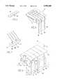
- FIG. 1is a front end view of the preferred embodiment of the modular jack assembly of the present invention
- FIG. 2is a rear end view of the modular jack assembly shown in FIG. 1;
- FIG. 3is a cross sectional view taken through line III--III in FIG. 5;
- FIG. 4is a top plan view of the modular jack assembly shown in FIG. 1;
- FIG. 5is a bottom plan view of the modular jack assembly shown in FIG. 1;
- FIG. 6is a perspective view of part of the insulated insert element of the modular jack assembly shown in FIG. 1;
- FIG. 7is a perspective view of the wire retaining element of the modular jack assembly shown in FIG. 1;
- FIG. 8is a perspective view of the grounding strip element of the modular jack assembly shown in FIG. 1;
- FIG. 9is the schematic view of the modular jack assembly similar to FIG. 3 in which common planes of the groups are illustrated.
- the outer insulative housingis shown generally at numeral 10.
- This housingincludes a top wall 12, a bottom wall 14 and a pair of opposed lateral walls 16 and 18.
- the material from which the housing is constructedis a thermoplastic polymer having suitable insulative properties.
- Within these wallsis an interior section 20 which has a rear open end 22 and a forward open end 24.
- Projecting upwardly from the bottom wall in this interior sectionthere is a medial wall generally shown at numeral 26 which has a rear side 28, a front side and an inclined top side 32 which slopes upwardly and forwardly from its rear side toward its front side.
- Adjacent to the lateral walls, the medial lateral extensions 34 and 36Adjacent to the lateral walls, the medial lateral extensions 34 and 36 which serve as projections to retain other elements as will be hereafter explained.
- Interposed between these lateral extensionsthere are a plurality of wire separation extensions as at 38, 40 and 42 and between these wire separation extensions there are plurality of slots at 44 and 46.
- the lateral wall 16includes a lower shoulder 54, another shoulder 56, a lower main wall 58, an upper main wall 60 and a recessed wall 62 interposed between the lower and upper main wall. It will be seen that the lateral wall 18 has substantially identical features as lateral wall 16. Referring particularly to FIGS. 3 and 6, the insulative insert shown generally at numeral 64 may be considered to be comprised of an upper section 66 and a lower section 68. Although in the embodiment illustrated in FIG.
- the insertmay comprise two separate upper and lower sections or only an upper section may be used as is shown in FIG. 6.
- the upper sectionincludes a base side 70, an upper side 72, a rear end 74 and a terminal end 76.
- On the upper sidethere are a plurality of upper side grooves as at 78 and at the terminal end there are terminal end grooves as at 80.
- the lower sectionincludes a bottom end 82 a top end 84 a front side 86 and a rear side 88.
- On this rear sidethere are a plurality of vertical grooves as at 90 which adjoin the grooves on the upper side of the upper section.
- the insulated insertis superimposed over a conductive wire retaining element 92 which engages one group of wires as is explained hereafter. Another group of wires is engaged by a grounding strip 94 having a grounding tab 96 as is also explained hereafter.
- first common planethere is a first group of wires 98, 100, 102 and 104.
- second group of wiresin a common plane which is made up of wires 106, 108, 110 and 112. It will be seen that the first group of wires are in a common first plane shown generally at 114.
- this first planethere is a vertical section 116 in which the wires extend upwardly from a point beneath the bottom wall of the insulated housing and from that bottom wall to the top wall of the insulated housing from where they extend horizontally toward the front end of the housing in horizontal section 118 of the plane and then extend rearwardly and downwardly toward the rear end of the housing in angular oblique section of the plane 120.
- the second group of wiresis in a second plane shown generally at numeral 124. In this plane the wires extend first upwardly from below the bottom wall of the housing in a common vertical section of the plane 126. Before reaching the top wall of the housing and preferably at a point medially between the bottom and top wall, the wires in the second plane extend forwardly and upwardly into the interior of the housing in angular oblique section 128 of the second plane. This oblique section ends in a terminal edge 130.
- This common planeincludes wires 106, 108, 110 and 112. It will be noted that there is an angle a 2 between the vertical section and the oblique section of the second plane. It will also be noted that there is a distance g which is the longitudinal distance between the terminal edges of the first plane and the second plane. It will also be noted that in both the first plane and the second plane there is uniform distance between adjacent wires in the first group and the second group of wires which is shown, for example, as d 1 in the first group of wires and d 2 in the second group of wires. The distance between the vertical sections of the first and second planes is shown as d 3 . The distance between the oblique sections of the first and second planes is shown as d 4 .
- the distance 1is from 0.2 inch to 2.0 inch and the distance g is from 0.2 inch to 1.0 inch while the distances d 1 and d 2 are from 0.040 inch to 0.250 inch.
- d 3is from 0.040 inch to 0.200 inch, and d 4 is from 0.0 inch to 0.3 inch.
- Angle a 1will preferably be from 15° to 70°, and angle a 2 will preferably be 105° to 160°.
- the wireswill preferably be from 0.01 inch to 0.05 inch in diameter.
- the overall lengths of the wires in the first planewill be from 1.0 inch to 3.0 inch, and the overall lengths of the wires in the second plane will be from 0.5 inch to 1.5 inch.
- the overall lengths of the wires in the first groupwas 1.75 inch.
- the overall lengths of the wires in the second groupwas 0.75 inch.
- Eight wireswere arranged in substantially the same pattern as is shown in FIG. 5. For the purpose of this description the positions shown in FIG. 5 will be referred to as shown in the following Table I.
- JACK 1One jack (JACK 1) was manufactured in the conventional manner so that all the wires extended vertically from the bottom wall of the housing then horizontally forward then downwardly and rearwardly back toward the rear open end.
- two to four wireswere positioned generally as described above in the second plane as at numeral 124 in FIG. 9.
- the other wiresextended upwardly, horizontally then downwardly and rearwardly generally as in the first plane 114 in FIG. 9 or in a plane parallel to such a plane.
- Table 2The specific positioning of the wires is shown according to the following Table 2.
- the length 1was 0.6 inch, and angle a 1 was 30°.
- the length gwas 0.4 inch and angle a 2 was 120°.
- the distances between wires in each row (d 1 and d 2 )was 0.100 inch in all the jacks.
- the distance between the rows (d 3 )was 0.100 inch in all the jacks.
- the transverse distance between the oblique planes of wires (d 4 ) in JACK 2, JACK 3 and JACK 4was 0.020 inch.
- the wireswere 0.020 inch in diameter and had an overall length of about 1.75 inch for wires positioned in the first plane and about 0.75 inch for wires positioned in the insulative housing.
- the insulative housing and insulative insertwere a polyester resin. The following test was performed on these modular jacks.
- Transmission performance of connecting hardware for UTP cablingwas determined by evaluating its impact upon measurements of attenuation, NEXT less and return loss for a pair of 100 ⁇ balanced 24 AWG (0.02 inch) test leads. After calibration, reference sweeps were performed the test leads and impedance matching terminations were connected to the test sample and connector transmission performance data was collected for each parameter. With the network analyzer calibrated to factor out the combined attenuation of the baluns and test leads; 100 ⁇ resistors were connected across each of the two balanced outputs of the test baluns. In order to minimize inductive effects, the resistor leads were kept as shod as possible (0.2 inch or less per side).
- the cable pairswere positioned such that they are sequenced 1& 2, 3& 6, 4 & 5 and 7 & 8 respectively.
- the side-by-side orientation of the test leadsextended into the jacket a distance of at least 0.3 inch, creating a flat portion.
- the flat, jacketed portion of the test leadsappeared to be oblong in cross-section.
- the plugwas then mated with the test jack and NEXT loss measurements were performed. Results of this test were shown in the attached Table 3.
- a jack of the present inventionso that at least one wire may extend vertically through the lower vertical section of the second plane and continue to extend vertically to the top wall and then extend horizontally adjacent the top wall and then downwardly and rearwardly toward the rear open end.
- Examples of such wireswould be wires 1 and 7 in JACK 3 and wire 1 in JACK 4.
Landscapes
- Engineering & Computer Science (AREA)
- Manufacturing & Machinery (AREA)
- Details Of Connecting Devices For Male And Female Coupling (AREA)
- Shielding Devices Or Components To Electric Or Magnetic Fields (AREA)
- Manufacturing Of Electrical Connectors (AREA)
- Coupling Device And Connection With Printed Circuit (AREA)
- Cable Transmission Systems, Equalization Of Radio And Reduction Of Echo (AREA)
Abstract
Description
TABLE 2 ______________________________________ WIRES IN FIRST PLANE OR WIRES IN SECOND JACK PARALLEL TO PLANE ______________________________________ 1 1-8NONE 2 1, 3, 5, 7 2, 4, 6, 8 3 1, 2, 4, 6, 7, 8 3, 5 4 1, 2, 4, 6, 8 3, 5, 7 ______________________________________
TABLE 3 ______________________________________ CROSSTALK BETWEEN WIRES (dB)JACK 1 & 2 1 & 3 1 & 4 2 & 3 2 & 4 3 & 4 ______________________________________ 1 -32.9 -43.0 -47.0 -42.0 -41.7 -52.0 2 -40.5 -41.7 -41.2 -50.4 -44.6 -52.3 3 -40.8 -41.7 -50.8 -52.0 -42.5 -80.4 4 -40.6 -48.4 -46.6 -44.6 -54.0 -80.6 ______________________________________
Claims (20)
Priority Applications (14)
| Application Number | Priority Date | Filing Date | Title |
|---|---|---|---|
| US08/346,640US5599209A (en) | 1994-11-30 | 1994-11-30 | Method of reducing electrical crosstalk and common mode electromagnetic interference and modular jack for use therein |
| TW084100133ATW307931B (en) | 1994-11-30 | 1995-01-09 | |
| DE69529687TDE69529687T2 (en) | 1994-11-30 | 1995-11-30 | MODULAR PLUG AND METHOD FOR REDUCING CROSS-OVERVIEW AND ELECTROMAGNETIC INTERFERENCES |
| CN95196524ACN1095225C (en) | 1994-11-30 | 1995-11-30 | Modular jack and method of reducing crosstalk and electromagnetic interference |
| JP8519333AJPH10510666A (en) | 1994-11-30 | 1995-11-30 | Modular jack and method for reducing crosstalk and electromagnetic interference |
| PCT/US1995/017116WO1996017411A1 (en) | 1994-11-30 | 1995-11-30 | Modular jack and method of reducing crosstalk and electromagnetic interference |
| KR1019970703604AKR980700711A (en) | 1994-11-30 | 1995-11-30 | Modular Jack and Method of Reducing Crosstalk and Electromagnetic Interference |
| EP95943991AEP0795215B1 (en) | 1994-11-30 | 1995-11-30 | Modular jack and method of reducing crosstalk and electromagnetic interference |
| US08/597,072US5687478A (en) | 1994-11-30 | 1996-04-19 | Method of reducing electrical crosstalk and common mode electromagnetic interference |
| US08/643,241US5759070A (en) | 1994-11-30 | 1996-05-02 | Modular jack insert |
| US08/846,699US6113422A (en) | 1994-11-30 | 1997-04-30 | Connector with circuit devices and indicators |
| US09/610,433US6276971B1 (en) | 1994-11-30 | 2000-07-05 | Electrical connector with reduced cross-talk and electromagnetic interference |
| US09/770,755US20010024893A1 (en) | 1994-11-30 | 2001-01-25 | Electrical connector with reduced cross-talk and electromagnetic interference |
| US10/038,043US20020123270A1 (en) | 1994-11-30 | 2002-01-04 | Electrical connector with reduced cross-talk and electromagnetic interference |
Applications Claiming Priority (1)
| Application Number | Priority Date | Filing Date | Title |
|---|---|---|---|
| US08/346,640US5599209A (en) | 1994-11-30 | 1994-11-30 | Method of reducing electrical crosstalk and common mode electromagnetic interference and modular jack for use therein |
Related Child Applications (2)
| Application Number | Title | Priority Date | Filing Date |
|---|---|---|---|
| US08/597,072DivisionUS5687478A (en) | 1994-11-30 | 1996-04-19 | Method of reducing electrical crosstalk and common mode electromagnetic interference |
| US08/643,241Continuation-In-PartUS5759070A (en) | 1994-11-30 | 1996-05-02 | Modular jack insert |
Publications (1)
| Publication Number | Publication Date |
|---|---|
| US5599209Atrue US5599209A (en) | 1997-02-04 |
Family
ID=23360351
Family Applications (6)
| Application Number | Title | Priority Date | Filing Date |
|---|---|---|---|
| US08/346,640Expired - LifetimeUS5599209A (en) | 1994-11-30 | 1994-11-30 | Method of reducing electrical crosstalk and common mode electromagnetic interference and modular jack for use therein |
| US08/597,072Expired - LifetimeUS5687478A (en) | 1994-11-30 | 1996-04-19 | Method of reducing electrical crosstalk and common mode electromagnetic interference |
| US08/643,241Expired - LifetimeUS5759070A (en) | 1994-11-30 | 1996-05-02 | Modular jack insert |
| US09/610,433Expired - LifetimeUS6276971B1 (en) | 1994-11-30 | 2000-07-05 | Electrical connector with reduced cross-talk and electromagnetic interference |
| US09/770,755AbandonedUS20010024893A1 (en) | 1994-11-30 | 2001-01-25 | Electrical connector with reduced cross-talk and electromagnetic interference |
| US10/038,043AbandonedUS20020123270A1 (en) | 1994-11-30 | 2002-01-04 | Electrical connector with reduced cross-talk and electromagnetic interference |
Family Applications After (5)
| Application Number | Title | Priority Date | Filing Date |
|---|---|---|---|
| US08/597,072Expired - LifetimeUS5687478A (en) | 1994-11-30 | 1996-04-19 | Method of reducing electrical crosstalk and common mode electromagnetic interference |
| US08/643,241Expired - LifetimeUS5759070A (en) | 1994-11-30 | 1996-05-02 | Modular jack insert |
| US09/610,433Expired - LifetimeUS6276971B1 (en) | 1994-11-30 | 2000-07-05 | Electrical connector with reduced cross-talk and electromagnetic interference |
| US09/770,755AbandonedUS20010024893A1 (en) | 1994-11-30 | 2001-01-25 | Electrical connector with reduced cross-talk and electromagnetic interference |
| US10/038,043AbandonedUS20020123270A1 (en) | 1994-11-30 | 2002-01-04 | Electrical connector with reduced cross-talk and electromagnetic interference |
Country Status (8)
| Country | Link |
|---|---|
| US (6) | US5599209A (en) |
| EP (1) | EP0795215B1 (en) |
| JP (1) | JPH10510666A (en) |
| KR (1) | KR980700711A (en) |
| CN (1) | CN1095225C (en) |
| DE (1) | DE69529687T2 (en) |
| TW (1) | TW307931B (en) |
| WO (1) | WO1996017411A1 (en) |
Cited By (49)
| Publication number | Priority date | Publication date | Assignee | Title |
|---|---|---|---|---|
| WO1998006152A1 (en)* | 1996-08-02 | 1998-02-12 | Berg Technology, Inc. | Connector with circuit devices and indicators |
| US5791942A (en)* | 1994-01-11 | 1998-08-11 | Stewart Connector Systems, Inc. | High frequency electrical connector |
| GB2332786A (en)* | 1997-11-04 | 1999-06-30 | Richard Weatherley | Plug and mating socket for data transmission systems |
| US6036547A (en)* | 1998-03-05 | 2000-03-14 | Berg Technology, Inc. | Double deck gang jack exhibiting suppressed mutual crosstalk |
| US6042393A (en)* | 1998-05-29 | 2000-03-28 | The Whitaker Corporation | Support for compliant pin terminals |
| EP0992085A4 (en)* | 1997-06-23 | 2000-09-27 | Berg Electronics Mfg | HIGH SPEED MODULAR JACK WITH SELF-SWINGING CONTACT |
| US6135819A (en)* | 1999-05-19 | 2000-10-24 | Lin; Chang-Liang | Telecommunication socket capable of directly inserting or connecting with a modularized circuit |
| JP2000299164A (en)* | 1999-04-01 | 2000-10-24 | Berg Technol Inc | Electric connector reducing electric cross talk and common mode electromagnetic interference |
| US6171153B1 (en)* | 1996-02-29 | 2001-01-09 | Berg Technology, Inc. | Modular jack assembly and universal housing for use therein |
| US6176742B1 (en)* | 1999-06-25 | 2001-01-23 | Avaya Inc. | Capacitive crosstalk compensation arrangement for communication connectors |
| US6179667B1 (en)* | 1998-06-16 | 2001-01-30 | Stewart Connector Systems, Inc. | High frequency electrical connector assembly with forward facing contact/terminal member securing insert |
| US6183306B1 (en) | 1997-11-21 | 2001-02-06 | Panduit Corp. | Staggered interface contacts |
| US6244906B1 (en) | 1999-12-21 | 2001-06-12 | Avaya Technology Corp. | Low cross talk plug and jack |
| US6267628B1 (en) | 1998-06-02 | 2001-07-31 | Stewart Connector Systems, Inc. | High frequency electrical connector assembly such as a multi-port multi-level connector assembly |
| US6276971B1 (en) | 1994-11-30 | 2001-08-21 | Berg Technology, Inc. | Electrical connector with reduced cross-talk and electromagnetic interference |
| US6305950B1 (en) | 2000-01-14 | 2001-10-23 | Panduit Corp. | Low crosstalk modular communication connector |
| US6325672B1 (en) | 1999-10-16 | 2001-12-04 | Berg Technology, Inc. | Electrical connector with internal shield and filter |
| US6331126B1 (en) | 2000-09-07 | 2001-12-18 | Sentinel Holding, Inc. | High speed modular jack |
| US6346010B1 (en) | 2000-08-10 | 2002-02-12 | The Wiremold Company | Modular connector |
| US6361354B1 (en)* | 1998-03-23 | 2002-03-26 | The Siemon Company | Vertical and right angle modular outlets |
| US6383029B1 (en)* | 1997-07-10 | 2002-05-07 | Lk A/S | Method of reducing signal coupling in a connector, a connector and a cable including such a connector |
| US6390851B1 (en) | 1999-10-16 | 2002-05-21 | Berg Technology, Inc. | Electrical connector with internal shield |
| US20020061684A1 (en)* | 2000-09-29 | 2002-05-23 | Aekins Robert A. | Low noise communication modular connnector insert |
| EP0971460A3 (en)* | 1998-06-30 | 2002-07-31 | Berg Electronics Manufacturing B.V. | Vertical modular connector having low electrical crosstalk |
| US6435918B1 (en)* | 2000-09-18 | 2002-08-20 | Surtec Industries Inc. | Reduced return loss electrical connector |
| US6533618B1 (en) | 2000-03-31 | 2003-03-18 | Ortronics, Inc. | Bi-directional balance low noise communication interface |
| US6554638B1 (en)* | 1998-10-14 | 2003-04-29 | Stewart Connector Systems, Inc. | Modular electrical connector assemblies with magnetic filter and/or visual indicator |
| US6579116B2 (en) | 2001-03-12 | 2003-06-17 | Sentinel Holding, Inc. | High speed modular connector |
| US20030128838A1 (en)* | 2002-01-07 | 2003-07-10 | Lenz Vernon C. | Releaseable hardhat mount for speaker/mike |
| US6602097B1 (en) | 1994-01-11 | 2003-08-05 | Stewart Connector Systems, Inc. | High frequency electrical connector |
| US20040033728A1 (en)* | 2000-09-15 | 2004-02-19 | Richard Weatherley | Jack for data transmission |
| US6729901B2 (en) | 2000-09-29 | 2004-05-04 | Ortronics, Inc. | Wire guide sled hardware for communication plug |
| US20050064747A1 (en)* | 2003-09-19 | 2005-03-24 | Yalei Xue | Modular jack connector |
| US20050095920A1 (en)* | 2001-03-28 | 2005-05-05 | Aekins Robert A. | Dual reactance low noise modular connector insert |
| US20050095919A1 (en)* | 2001-04-05 | 2005-05-05 | Aekins Robert A. | Dual reactance low noise modular connector insert |
| US20050181705A1 (en)* | 2004-02-13 | 2005-08-18 | Kathy Maupin | Post surgical binder |
| US6962503B2 (en) | 2000-01-10 | 2005-11-08 | Ortronics, Inc. | Unshielded twisted pair (UTP) wire stabilizer for communication plug |
| US7288001B1 (en) | 2006-09-20 | 2007-10-30 | Ortronics, Inc. | Electrically isolated shielded multiport connector assembly |
| US20070293094A1 (en)* | 2006-06-15 | 2007-12-20 | Aekins Robert A | Low noise multiport connector |
| US20080081492A1 (en)* | 2006-09-29 | 2008-04-03 | Nellcor Puritan Bennett Incorporated | Device and method for reducing crosstalk |
| US7384300B1 (en)* | 1999-12-22 | 2008-06-10 | Xerox Corporation | Method and apparatus for a connection sensing apparatus |
| US20080311778A1 (en)* | 2007-06-14 | 2008-12-18 | Aekins Robert A | Modular insert and jack including bi-sectional lead frames |
| US20080311797A1 (en)* | 2007-06-14 | 2008-12-18 | Ortronics, Inc. | Modular connector exhibiting quad reactance balance functionality |
| USD612856S1 (en) | 2008-02-20 | 2010-03-30 | Vocollect Healthcare Systems, Inc. | Connector for a peripheral device |
| USD615040S1 (en) | 2009-09-09 | 2010-05-04 | Vocollect, Inc. | Electrical connector |
| US20110059642A1 (en)* | 2009-09-10 | 2011-03-10 | Gordon Slippy | Break-away electrical connector |
| US20110056723A1 (en)* | 2009-09-10 | 2011-03-10 | Vocollect, Inc. | Electrical cable with strength member |
| US20130017730A1 (en)* | 2011-07-14 | 2013-01-17 | Hon Hai Precision Industry Co., Ltd. | Electrical connector having contact module |
| CN113517611A (en)* | 2020-04-09 | 2021-10-19 | 财团法人工业技术研究院 | High-speed connectors with reduced crosstalk |
Families Citing this family (26)
| Publication number | Priority date | Publication date | Assignee | Title |
|---|---|---|---|---|
| US5911602A (en)* | 1996-07-23 | 1999-06-15 | Superior Modular Products Incorporated | Reduced cross talk electrical connector |
| US6633550B1 (en) | 1997-02-20 | 2003-10-14 | Telefonaktiebolaget Lm Ericsson (Publ) | Radio transceiver on a chip |
| TW362823U (en)* | 1998-03-13 | 1999-06-21 | Hon Hai Prec Ind Co Ltd | Electric connector |
| US6083052A (en)* | 1998-03-23 | 2000-07-04 | The Siemon Company | Enhanced performance connector |
| US6368144B2 (en) | 1998-03-23 | 2002-04-09 | The Siemon Company | Enhanced performance modular outlet |
| US6120329A (en)* | 1998-05-08 | 2000-09-19 | The Whitaker Corporation | Modular jack with anti-cross-talk contacts and method of making same |
| US6334792B1 (en) | 1999-01-15 | 2002-01-01 | Adc Telecommunications, Inc. | Connector including reduced crosstalk spring insert |
| JP2002535809A (en)* | 1999-01-15 | 2002-10-22 | エーデーシー・テレコミュニケーションズ・インコーポレーテッド | Communication Jack Assembly |
| TW531945B (en) | 1999-01-28 | 2003-05-11 | Bel Fuse Inc | RJ jack with integrated interface magnetics |
| TW444959U (en)* | 1999-02-19 | 2001-07-01 | Berg Electronics Mfg | Modular jack with lead frame insert |
| US6190210B1 (en)* | 1999-03-10 | 2001-02-20 | Berg Technology, Inc. | Low profile modular jack |
| US6089923A (en) | 1999-08-20 | 2000-07-18 | Adc Telecommunications, Inc. | Jack including crosstalk compensation for printed circuit board |
| US6520806B2 (en)* | 1999-08-20 | 2003-02-18 | Adc Telecommunications, Inc. | Telecommunications connector for high frequency transmissions |
| TW479861U (en)* | 2000-01-25 | 2002-03-11 | Hon Hai Prec Ind Co Ltd | Electrical connector |
| TW464091U (en)* | 2000-12-20 | 2001-11-11 | Hon Hai Prec Ind Co Ltd | Electrical connector |
| JP2003242873A (en)* | 2002-02-19 | 2003-08-29 | Fujitsu Component Ltd | Micro-relay |
| US6814624B2 (en)* | 2002-11-22 | 2004-11-09 | Adc Telecommunications, Inc. | Telecommunications jack assembly |
| US8056224B2 (en)* | 2006-05-19 | 2011-11-15 | John Peng | Method of manufacturing a network jack |
| US7371118B2 (en)* | 2006-08-25 | 2008-05-13 | Hon Hai Precision Ind. Co., Ltd | Electrical connector assembly with reduced crosstalk and electromaganetic interference |
| TWM337173U (en)* | 2007-12-17 | 2008-07-21 | Hipro Electronics Taiwan Co Ltd | Pin fixing base and electronic device containing the same |
| JP4795444B2 (en)* | 2009-02-09 | 2011-10-19 | ホシデン株式会社 | connector |
| US8602801B2 (en)* | 2012-02-23 | 2013-12-10 | Hewlett-Packard Development Company, L.P. | Electrical jack |
| CN105408747A (en) | 2013-05-23 | 2016-03-16 | 快速诊断技术公司 | Resonator sensor module system and method |
| EP3000177A4 (en) | 2013-05-23 | 2016-12-28 | Rapid Diagnostek Inc | Interconnect device and module using same |
| JP6149753B2 (en)* | 2014-02-17 | 2017-06-21 | 日立金属株式会社 | connector |
| DE102016003535A1 (en)* | 2016-03-22 | 2017-09-28 | Yamaichi Electronics Deutschland Gmbh | Network socket and method for picking up and electrically contacting a network plug |
Citations (11)
| Publication number | Priority date | Publication date | Assignee | Title |
|---|---|---|---|---|
| US4457570A (en)* | 1980-02-12 | 1984-07-03 | Virginia Patent Development Corporation | Connector for mating modular plug with printed circuit board |
| US4703991A (en)* | 1986-01-10 | 1987-11-03 | Stewart Stamping Corporation | Low profile jack |
| US5030123A (en)* | 1989-03-24 | 1991-07-09 | Adc Telecommunications, Inc. | Connector and patch panel for digital video and data |
| US5123854A (en)* | 1991-03-13 | 1992-06-23 | Molex Incorporated | Shunted electrical connector |
| US5299956A (en)* | 1992-03-23 | 1994-04-05 | Superior Modular Products, Inc. | Low cross talk electrical connector system |
| US5312273A (en)* | 1992-08-11 | 1994-05-17 | Molex Incorporated | Shielded modular jack |
| US5346405A (en)* | 1993-05-04 | 1994-09-13 | The Whitaker Corporation | Shunted connector assembly and shunt assembly therefor |
| US5364294A (en)* | 1991-12-24 | 1994-11-15 | Stewart Connector Systems, Inc. | Electrical device for surface mounting on a circuit board and mounting component thereof |
| WO1995019056A1 (en)* | 1994-01-11 | 1995-07-13 | Stewart Connector Systems, Inc. | Improved high frequency electrical connector |
| US5456619A (en)* | 1994-08-31 | 1995-10-10 | Berg Technology, Inc. | Filtered modular jack assembly and method of use |
| US5470244A (en)* | 1993-10-05 | 1995-11-28 | Thomas & Betts Corporation | Electrical connector having reduced cross-talk |
Family Cites Families (11)
| Publication number | Priority date | Publication date | Assignee | Title |
|---|---|---|---|---|
| US5478261A (en)* | 1978-06-14 | 1995-12-26 | Virginia Patent Development Corp. | Modular jack for directly coupling modular plug with printed circuit board |
| US4292736A (en)* | 1978-09-08 | 1981-10-06 | Amp Incorporated | Method for making jack type receptacles |
| US4296550A (en)* | 1978-09-20 | 1981-10-27 | Amp Incorporated | Method of manufacturing electrical connector receptacle |
| US4231628A (en)* | 1978-12-14 | 1980-11-04 | Amp Incorporated | Electrical connector receptacles |
| US4786259A (en)* | 1984-02-27 | 1988-11-22 | Hayes Microcomputer Products, Inc. | Low profile modular receptacle and method of making same |
| US4541174A (en)* | 1984-06-04 | 1985-09-17 | Allied Corporation | Process of making a jack-type electrical connector |
| JPS61227380A (en)* | 1985-04-01 | 1986-10-09 | ヒロセ電機株式会社 | Electrical connector receptacle and its manufacturing method |
| US4618207A (en)* | 1985-06-05 | 1986-10-21 | Molex Incorporated | Two piece modular receptacle |
| JPH0538547Y2 (en)* | 1988-12-09 | 1993-09-29 | ||
| US5310360A (en)* | 1993-05-18 | 1994-05-10 | Molex Incorporated | Circuit board mounted modular phone jack |
| US5599209A (en) | 1994-11-30 | 1997-02-04 | Berg Technology, Inc. | Method of reducing electrical crosstalk and common mode electromagnetic interference and modular jack for use therein |
- 1994
- 1994-11-30USUS08/346,640patent/US5599209A/ennot_activeExpired - Lifetime
- 1995
- 1995-01-09TWTW084100133Apatent/TW307931B/zhactive
- 1995-11-30EPEP95943991Apatent/EP0795215B1/ennot_activeExpired - Lifetime
- 1995-11-30JPJP8519333Apatent/JPH10510666A/enactivePending
- 1995-11-30KRKR1019970703604Apatent/KR980700711A/ennot_activeCeased
- 1995-11-30WOPCT/US1995/017116patent/WO1996017411A1/ennot_activeApplication Discontinuation
- 1995-11-30CNCN95196524Apatent/CN1095225C/ennot_activeExpired - Fee Related
- 1995-11-30DEDE69529687Tpatent/DE69529687T2/ennot_activeExpired - Fee Related
- 1996
- 1996-04-19USUS08/597,072patent/US5687478A/ennot_activeExpired - Lifetime
- 1996-05-02USUS08/643,241patent/US5759070A/ennot_activeExpired - Lifetime
- 2000
- 2000-07-05USUS09/610,433patent/US6276971B1/ennot_activeExpired - Lifetime
- 2001
- 2001-01-25USUS09/770,755patent/US20010024893A1/ennot_activeAbandoned
- 2002
- 2002-01-04USUS10/038,043patent/US20020123270A1/ennot_activeAbandoned
Patent Citations (14)
| Publication number | Priority date | Publication date | Assignee | Title |
|---|---|---|---|---|
| US4457570A (en)* | 1980-02-12 | 1984-07-03 | Virginia Patent Development Corporation | Connector for mating modular plug with printed circuit board |
| US4703991A (en)* | 1986-01-10 | 1987-11-03 | Stewart Stamping Corporation | Low profile jack |
| US4703991B1 (en)* | 1986-01-10 | 1997-05-13 | Stewart Connector Systems Inc | Low profile jack |
| US5030123A (en)* | 1989-03-24 | 1991-07-09 | Adc Telecommunications, Inc. | Connector and patch panel for digital video and data |
| US5123854A (en)* | 1991-03-13 | 1992-06-23 | Molex Incorporated | Shunted electrical connector |
| US5364294A (en)* | 1991-12-24 | 1994-11-15 | Stewart Connector Systems, Inc. | Electrical device for surface mounting on a circuit board and mounting component thereof |
| US5299956B1 (en)* | 1992-03-23 | 1995-10-24 | Superior Modular Prod Inc | Low cross talk electrical connector system |
| US5299956A (en)* | 1992-03-23 | 1994-04-05 | Superior Modular Products, Inc. | Low cross talk electrical connector system |
| US5310363A (en)* | 1992-03-23 | 1994-05-10 | Superior Modular Products Incorporated | Impedance matched reduced cross talk electrical connector system |
| US5312273A (en)* | 1992-08-11 | 1994-05-17 | Molex Incorporated | Shielded modular jack |
| US5346405A (en)* | 1993-05-04 | 1994-09-13 | The Whitaker Corporation | Shunted connector assembly and shunt assembly therefor |
| US5470244A (en)* | 1993-10-05 | 1995-11-28 | Thomas & Betts Corporation | Electrical connector having reduced cross-talk |
| WO1995019056A1 (en)* | 1994-01-11 | 1995-07-13 | Stewart Connector Systems, Inc. | Improved high frequency electrical connector |
| US5456619A (en)* | 1994-08-31 | 1995-10-10 | Berg Technology, Inc. | Filtered modular jack assembly and method of use |
Non-Patent Citations (2)
| Title |
|---|
| Bob Strich, "Developments in LAN Cabling & Connectors" Interconnection Technology, Dec. 1993. |
| Bob Strich, Developments in LAN Cabling & Connectors Interconnection Technology , Dec. 1993.* |
Cited By (81)
| Publication number | Priority date | Publication date | Assignee | Title |
|---|---|---|---|---|
| US5791942A (en)* | 1994-01-11 | 1998-08-11 | Stewart Connector Systems, Inc. | High frequency electrical connector |
| US6602097B1 (en) | 1994-01-11 | 2003-08-05 | Stewart Connector Systems, Inc. | High frequency electrical connector |
| US6113422A (en)* | 1994-11-30 | 2000-09-05 | Berg Technology, Inc. | Connector with circuit devices and indicators |
| US6276971B1 (en) | 1994-11-30 | 2001-08-21 | Berg Technology, Inc. | Electrical connector with reduced cross-talk and electromagnetic interference |
| US6171153B1 (en)* | 1996-02-29 | 2001-01-09 | Berg Technology, Inc. | Modular jack assembly and universal housing for use therein |
| WO1998006152A1 (en)* | 1996-08-02 | 1998-02-12 | Berg Technology, Inc. | Connector with circuit devices and indicators |
| US6312290B1 (en) | 1997-06-23 | 2001-11-06 | Fci Americas Technology, Inc. | High speed IDC modular jack |
| EP0992085A4 (en)* | 1997-06-23 | 2000-09-27 | Berg Electronics Mfg | HIGH SPEED MODULAR JACK WITH SELF-SWINGING CONTACT |
| US6383029B1 (en)* | 1997-07-10 | 2002-05-07 | Lk A/S | Method of reducing signal coupling in a connector, a connector and a cable including such a connector |
| GB2332786A (en)* | 1997-11-04 | 1999-06-30 | Richard Weatherley | Plug and mating socket for data transmission systems |
| GB2332786B (en)* | 1997-11-04 | 2001-10-10 | Richard Weatherley | Plug and mating socket for data transmission systems |
| US6183306B1 (en) | 1997-11-21 | 2001-02-06 | Panduit Corp. | Staggered interface contacts |
| US6036547A (en)* | 1998-03-05 | 2000-03-14 | Berg Technology, Inc. | Double deck gang jack exhibiting suppressed mutual crosstalk |
| US6361354B1 (en)* | 1998-03-23 | 2002-03-26 | The Siemon Company | Vertical and right angle modular outlets |
| US6042393A (en)* | 1998-05-29 | 2000-03-28 | The Whitaker Corporation | Support for compliant pin terminals |
| US6267628B1 (en) | 1998-06-02 | 2001-07-31 | Stewart Connector Systems, Inc. | High frequency electrical connector assembly such as a multi-port multi-level connector assembly |
| US6179667B1 (en)* | 1998-06-16 | 2001-01-30 | Stewart Connector Systems, Inc. | High frequency electrical connector assembly with forward facing contact/terminal member securing insert |
| EP0971460A3 (en)* | 1998-06-30 | 2002-07-31 | Berg Electronics Manufacturing B.V. | Vertical modular connector having low electrical crosstalk |
| US6554638B1 (en)* | 1998-10-14 | 2003-04-29 | Stewart Connector Systems, Inc. | Modular electrical connector assemblies with magnetic filter and/or visual indicator |
| US6394854B1 (en) | 1999-04-01 | 2002-05-28 | Fci Americas Technology, Inc. | Electrical connector for reducing electrical crosstalk and common mode electromagnetic interference |
| JP2000299164A (en)* | 1999-04-01 | 2000-10-24 | Berg Technol Inc | Electric connector reducing electric cross talk and common mode electromagnetic interference |
| US6280256B1 (en) | 1999-04-01 | 2001-08-28 | Bergtechnology, Inc. | Electrical connector for reducing electrical crosstalk and common mode electromagnetic interference |
| US6135819A (en)* | 1999-05-19 | 2000-10-24 | Lin; Chang-Liang | Telecommunication socket capable of directly inserting or connecting with a modularized circuit |
| AU778434B2 (en)* | 1999-06-25 | 2004-12-02 | Avaya Technology Corp. | Capacitive crosstalk compensation arrangement for communication connectors |
| US6176742B1 (en)* | 1999-06-25 | 2001-01-23 | Avaya Inc. | Capacitive crosstalk compensation arrangement for communication connectors |
| US6390851B1 (en) | 1999-10-16 | 2002-05-21 | Berg Technology, Inc. | Electrical connector with internal shield |
| US6325672B1 (en) | 1999-10-16 | 2001-12-04 | Berg Technology, Inc. | Electrical connector with internal shield and filter |
| US6244906B1 (en) | 1999-12-21 | 2001-06-12 | Avaya Technology Corp. | Low cross talk plug and jack |
| US7814240B2 (en) | 1999-12-22 | 2010-10-12 | Xerox Corporation | Method and apparatus for a connection sensing apparatus |
| US20080196519A1 (en)* | 1999-12-22 | 2008-08-21 | Xerox Corporation | Method and apparatus for a connection sensing apparatus |
| US7384300B1 (en)* | 1999-12-22 | 2008-06-10 | Xerox Corporation | Method and apparatus for a connection sensing apparatus |
| US6962503B2 (en) | 2000-01-10 | 2005-11-08 | Ortronics, Inc. | Unshielded twisted pair (UTP) wire stabilizer for communication plug |
| US6305950B1 (en) | 2000-01-14 | 2001-10-23 | Panduit Corp. | Low crosstalk modular communication connector |
| US6533618B1 (en) | 2000-03-31 | 2003-03-18 | Ortronics, Inc. | Bi-directional balance low noise communication interface |
| US6346010B1 (en) | 2000-08-10 | 2002-02-12 | The Wiremold Company | Modular connector |
| US6331126B1 (en) | 2000-09-07 | 2001-12-18 | Sentinel Holding, Inc. | High speed modular jack |
| US6869317B2 (en)* | 2000-09-15 | 2005-03-22 | Hellermanntyton Data Limited | Jack for data transmission |
| US20040033728A1 (en)* | 2000-09-15 | 2004-02-19 | Richard Weatherley | Jack for data transmission |
| US6435918B1 (en)* | 2000-09-18 | 2002-08-20 | Surtec Industries Inc. | Reduced return loss electrical connector |
| US20020061684A1 (en)* | 2000-09-29 | 2002-05-23 | Aekins Robert A. | Low noise communication modular connnector insert |
| US6802743B2 (en) | 2000-09-29 | 2004-10-12 | Ortronics, Inc. | Low noise communication modular connector insert |
| US20040235359A1 (en)* | 2000-09-29 | 2004-11-25 | Aekins Robert A. | Low noise communication modular connector insert |
| US6893296B2 (en) | 2000-09-29 | 2005-05-17 | Ortronics, Inc. | Low noise communication modular connector insert |
| US20050118881A1 (en)* | 2000-09-29 | 2005-06-02 | Aekins Robert A. | Low noise communication modular connector insert |
| US6729901B2 (en) | 2000-09-29 | 2004-05-04 | Ortronics, Inc. | Wire guide sled hardware for communication plug |
| US6579116B2 (en) | 2001-03-12 | 2003-06-17 | Sentinel Holding, Inc. | High speed modular connector |
| US20050095920A1 (en)* | 2001-03-28 | 2005-05-05 | Aekins Robert A. | Dual reactance low noise modular connector insert |
| US6896557B2 (en) | 2001-03-28 | 2005-05-24 | Ortronics, Inc. | Dual reactance low noise modular connector insert |
| US7037140B2 (en) | 2001-03-28 | 2006-05-02 | Ortronics, Inc. | Dual reactance low noise modular connector insert |
| US20050095919A1 (en)* | 2001-04-05 | 2005-05-05 | Aekins Robert A. | Dual reactance low noise modular connector insert |
| US7172466B2 (en) | 2001-04-05 | 2007-02-06 | Ortronics, Inc. | Dual reactance low noise modular connector insert |
| US20030128838A1 (en)* | 2002-01-07 | 2003-07-10 | Lenz Vernon C. | Releaseable hardhat mount for speaker/mike |
| US6923689B2 (en)* | 2003-09-19 | 2005-08-02 | Hon Hai Precision Ind. Co., Ltd. | Modular jack connector |
| US20050064747A1 (en)* | 2003-09-19 | 2005-03-24 | Yalei Xue | Modular jack connector |
| US20050181705A1 (en)* | 2004-02-13 | 2005-08-18 | Kathy Maupin | Post surgical binder |
| US7530854B2 (en) | 2006-06-15 | 2009-05-12 | Ortronics, Inc. | Low noise multiport connector |
| US20070293094A1 (en)* | 2006-06-15 | 2007-12-20 | Aekins Robert A | Low noise multiport connector |
| US7677931B2 (en) | 2006-06-15 | 2010-03-16 | Ortronics, Inc. | Method for multiport noise compensation |
| US20090191758A1 (en)* | 2006-06-15 | 2009-07-30 | Ortronics, Inc. | Method For Multiport Noise Compensation |
| US7288001B1 (en) | 2006-09-20 | 2007-10-30 | Ortronics, Inc. | Electrically isolated shielded multiport connector assembly |
| US20080081508A1 (en)* | 2006-09-29 | 2008-04-03 | Ken Sawatari | Device and method for reducing crosstalk |
| US20080081492A1 (en)* | 2006-09-29 | 2008-04-03 | Nellcor Puritan Bennett Incorporated | Device and method for reducing crosstalk |
| US7658652B2 (en) | 2006-09-29 | 2010-02-09 | Nellcor Puritan Bennett Llc | Device and method for reducing crosstalk |
| US7476131B2 (en) | 2006-09-29 | 2009-01-13 | Nellcor Puritan Bennett Llc | Device for reducing crosstalk |
| US7794266B2 (en) | 2006-09-29 | 2010-09-14 | Nellcor Puritan Bennett Llc | Device and method for reducing crosstalk |
| US20090163083A1 (en)* | 2006-09-29 | 2009-06-25 | Nellcor Puritan Bennett Llc | Device and method for reducing crosstalk |
| US20080311797A1 (en)* | 2007-06-14 | 2008-12-18 | Ortronics, Inc. | Modular connector exhibiting quad reactance balance functionality |
| US7481678B2 (en) | 2007-06-14 | 2009-01-27 | Ortronics, Inc. | Modular insert and jack including bi-sectional lead frames |
| US7658648B2 (en) | 2007-06-14 | 2010-02-09 | Ortronics, Inc. | Method for accommodating plugs with different contact layout geometries |
| US7485010B2 (en) | 2007-06-14 | 2009-02-03 | Ortronics, Inc. | Modular connector exhibiting quad reactance balance functionality |
| US20090191740A1 (en)* | 2007-06-14 | 2009-07-30 | Ortronics, Inc. | Method For Accommodating Plugs With Different Contact Layout Geometries |
| US20080311778A1 (en)* | 2007-06-14 | 2008-12-18 | Aekins Robert A | Modular insert and jack including bi-sectional lead frames |
| USD612856S1 (en) | 2008-02-20 | 2010-03-30 | Vocollect Healthcare Systems, Inc. | Connector for a peripheral device |
| USD615040S1 (en) | 2009-09-09 | 2010-05-04 | Vocollect, Inc. | Electrical connector |
| US20110059642A1 (en)* | 2009-09-10 | 2011-03-10 | Gordon Slippy | Break-away electrical connector |
| US20110056723A1 (en)* | 2009-09-10 | 2011-03-10 | Vocollect, Inc. | Electrical cable with strength member |
| US8241053B2 (en) | 2009-09-10 | 2012-08-14 | Vocollect, Inc. | Electrical cable with strength member |
| US8262403B2 (en) | 2009-09-10 | 2012-09-11 | Vocollect, Inc. | Break-away electrical connector |
| US20130017730A1 (en)* | 2011-07-14 | 2013-01-17 | Hon Hai Precision Industry Co., Ltd. | Electrical connector having contact module |
| US8758063B2 (en)* | 2011-07-14 | 2014-06-24 | Hon Hai Precision Industry Co., Ltd. | Electrical connector having a contact module with one set of terminals insert molded and a second set separately mounted |
| CN113517611A (en)* | 2020-04-09 | 2021-10-19 | 财团法人工业技术研究院 | High-speed connectors with reduced crosstalk |
Also Published As
| Publication number | Publication date |
|---|---|
| WO1996017411A1 (en) | 1996-06-06 |
| US20020123270A1 (en) | 2002-09-05 |
| US20010024893A1 (en) | 2001-09-27 |
| EP0795215B1 (en) | 2003-02-19 |
| US5687478A (en) | 1997-11-18 |
| CN1171860A (en) | 1998-01-28 |
| JPH10510666A (en) | 1998-10-13 |
| US6276971B1 (en) | 2001-08-21 |
| DE69529687D1 (en) | 2003-03-27 |
| EP0795215A4 (en) | 1998-02-11 |
| US5759070A (en) | 1998-06-02 |
| TW307931B (en) | 1997-06-11 |
| KR980700711A (en) | 1998-03-30 |
| DE69529687T2 (en) | 2003-10-23 |
| CN1095225C (en) | 2002-11-27 |
| EP0795215A1 (en) | 1997-09-17 |
Similar Documents
| Publication | Publication Date | Title |
|---|---|---|
| US5599209A (en) | Method of reducing electrical crosstalk and common mode electromagnetic interference and modular jack for use therein | |
| US6325672B1 (en) | Electrical connector with internal shield and filter | |
| EP0811258B1 (en) | High frequency modular plug and cable assembly | |
| US5431584A (en) | Electrical connector with reduced crosstalk | |
| US6402559B1 (en) | Modular electrical plug, plug-cable assemblies including the same, and load bar and terminal blade for same | |
| US7651380B2 (en) | Modular plugs and outlets having enhanced performance contacts | |
| EP0914695A1 (en) | Insert for a modular jack useful for reducing electrical crosstalk | |
| US6663419B2 (en) | Reduced crosstalk modular plug and patch cord incorporating the same | |
| GB2331873A (en) | Modular plug having compensating insert | |
| US6280256B1 (en) | Electrical connector for reducing electrical crosstalk and common mode electromagnetic interference | |
| US6312290B1 (en) | High speed IDC modular jack | |
| US6193542B1 (en) | Modular electrical plug and plug-cable assembly including the same | |
| EP0993081B1 (en) | Modular connector with capacitive plates | |
| US5593314A (en) | Staggered terminal array for mod plug | |
| US6409535B1 (en) | Modular electrical plug and plug-cable assembly including the same | |
| US6066005A (en) | Vertical modular connector having low electrical crosstalk | |
| CA2987615C (en) | Rj45 connector | |
| US7980883B2 (en) | Connecting block improved in crosstalk-characteristics | |
| US9583890B2 (en) | RJ45 connector |
Legal Events
| Date | Code | Title | Description |
|---|---|---|---|
| AS | Assignment | Owner name:BERG TECHNOLOGY, INC., NEVADA Free format text:ASSIGNMENT OF ASSIGNORS INTEREST;ASSIGNOR:BELOPOLSKY, YAKOV;REEL/FRAME:007431/0218 Effective date:19950227 | |
| STCF | Information on status: patent grant | Free format text:PATENTED CASE | |
| FPAY | Fee payment | Year of fee payment:4 | |
| FPAY | Fee payment | Year of fee payment:8 | |
| AS | Assignment | Owner name:BANC OF AMERICA SECURITIES LIMITED, AS SECURITY AG Free format text:SECURITY AGREEMENT;ASSIGNOR:FCI AMERICAS TECHNOLOGY, INC.;REEL/FRAME:017400/0192 Effective date:20060331 | |
| AS | Assignment | Owner name:FCI AMERICAS TECHNOLOGY, INC., NEVADA Free format text:CHANGE OF NAME;ASSIGNOR:BERG TECHNOLOGY, INC.;REEL/FRAME:017422/0729 Effective date:20000808 | |
| FPAY | Fee payment | Year of fee payment:12 | |
| AS | Assignment | Owner name:FCI AMERICAS TECHNOLOGY LLC, NEVADA Free format text:CONVERSION TO LLC;ASSIGNOR:FCI AMERICAS TECHNOLOGY, INC.;REEL/FRAME:025957/0432 Effective date:20090930 | |
| AS | Assignment | Owner name:FCI AMERICAS TECHNOLOGY LLC (F/K/A FCI AMERICAS TE Free format text:RELEASE OF PATENT SECURITY INTEREST AT REEL/FRAME NO. 17400/0192;ASSIGNOR:BANC OF AMERICA SECURITIES LIMITED;REEL/FRAME:029377/0632 Effective date:20121026 |