US5598487A - Hand-held data entry system removable signature pad - Google Patents
Hand-held data entry system removable signature padDownload PDFInfo
- Publication number
- US5598487A US5598487AUS08/306,073US30607394AUS5598487AUS 5598487 AUS5598487 AUS 5598487AUS 30607394 AUS30607394 AUS 30607394AUS 5598487 AUS5598487 AUS 5598487A
- Authority
- US
- United States
- Prior art keywords
- data
- module
- handwritten
- hand
- held
- Prior art date
- Legal status (The legal status is an assumption and is not a legal conclusion. Google has not performed a legal analysis and makes no representation as to the accuracy of the status listed.)
- Expired - Lifetime
Links
Images


Classifications
- H—ELECTRICITY
- H01—ELECTRIC ELEMENTS
- H01Q—ANTENNAS, i.e. RADIO AERIALS
- H01Q1/00—Details of, or arrangements associated with, antennas
- H01Q1/12—Supports; Mounting means
- H01Q1/22—Supports; Mounting means by structural association with other equipment or articles
- H01Q1/24—Supports; Mounting means by structural association with other equipment or articles with receiving set
- H01Q1/241—Supports; Mounting means by structural association with other equipment or articles with receiving set used in mobile communications, e.g. GSM
- H01Q1/242—Supports; Mounting means by structural association with other equipment or articles with receiving set used in mobile communications, e.g. GSM specially adapted for hand-held use
- G—PHYSICS
- G06—COMPUTING OR CALCULATING; COUNTING
- G06F—ELECTRIC DIGITAL DATA PROCESSING
- G06F1/00—Details not covered by groups G06F3/00 - G06F13/00 and G06F21/00
- G06F1/16—Constructional details or arrangements
- G06F1/1613—Constructional details or arrangements for portable computers
- G06F1/1626—Constructional details or arrangements for portable computers with a single-body enclosure integrating a flat display, e.g. Personal Digital Assistants [PDAs]
- G—PHYSICS
- G06—COMPUTING OR CALCULATING; COUNTING
- G06K—GRAPHICAL DATA READING; PRESENTATION OF DATA; RECORD CARRIERS; HANDLING RECORD CARRIERS
- G06K17/00—Methods or arrangements for effecting co-operative working between equipments covered by two or more of main groups G06K1/00 - G06K15/00, e.g. automatic card files incorporating conveying and reading operations
- G06K17/0022—Methods or arrangements for effecting co-operative working between equipments covered by two or more of main groups G06K1/00 - G06K15/00, e.g. automatic card files incorporating conveying and reading operations arrangements or provisions for transferring data to distant stations, e.g. from a sensing device
- G—PHYSICS
- G06—COMPUTING OR CALCULATING; COUNTING
- G06K—GRAPHICAL DATA READING; PRESENTATION OF DATA; RECORD CARRIERS; HANDLING RECORD CARRIERS
- G06K7/00—Methods or arrangements for sensing record carriers, e.g. for reading patterns
- G06K7/10—Methods or arrangements for sensing record carriers, e.g. for reading patterns by electromagnetic radiation, e.g. optical sensing; by corpuscular radiation
- G06K7/10544—Methods or arrangements for sensing record carriers, e.g. for reading patterns by electromagnetic radiation, e.g. optical sensing; by corpuscular radiation by scanning of the records by radiation in the optical part of the electromagnetic spectrum
- G06K7/10554—Moving beam scanning
- G06K7/10564—Light sources
- G06K7/10584—Source control
- G—PHYSICS
- G06—COMPUTING OR CALCULATING; COUNTING
- G06K—GRAPHICAL DATA READING; PRESENTATION OF DATA; RECORD CARRIERS; HANDLING RECORD CARRIERS
- G06K7/00—Methods or arrangements for sensing record carriers, e.g. for reading patterns
- G06K7/10—Methods or arrangements for sensing record carriers, e.g. for reading patterns by electromagnetic radiation, e.g. optical sensing; by corpuscular radiation
- G06K7/10544—Methods or arrangements for sensing record carriers, e.g. for reading patterns by electromagnetic radiation, e.g. optical sensing; by corpuscular radiation by scanning of the records by radiation in the optical part of the electromagnetic spectrum
- G06K7/10712—Fixed beam scanning
- G06K7/10722—Photodetector array or CCD scanning
- G—PHYSICS
- G06—COMPUTING OR CALCULATING; COUNTING
- G06K—GRAPHICAL DATA READING; PRESENTATION OF DATA; RECORD CARRIERS; HANDLING RECORD CARRIERS
- G06K7/00—Methods or arrangements for sensing record carriers, e.g. for reading patterns
- G06K7/10—Methods or arrangements for sensing record carriers, e.g. for reading patterns by electromagnetic radiation, e.g. optical sensing; by corpuscular radiation
- G06K7/10544—Methods or arrangements for sensing record carriers, e.g. for reading patterns by electromagnetic radiation, e.g. optical sensing; by corpuscular radiation by scanning of the records by radiation in the optical part of the electromagnetic spectrum
- G06K7/10821—Methods or arrangements for sensing record carriers, e.g. for reading patterns by electromagnetic radiation, e.g. optical sensing; by corpuscular radiation by scanning of the records by radiation in the optical part of the electromagnetic spectrum further details of bar or optical code scanning devices
- G06K7/10881—Methods or arrangements for sensing record carriers, e.g. for reading patterns by electromagnetic radiation, e.g. optical sensing; by corpuscular radiation by scanning of the records by radiation in the optical part of the electromagnetic spectrum further details of bar or optical code scanning devices constructional details of hand-held scanners
- G—PHYSICS
- G06—COMPUTING OR CALCULATING; COUNTING
- G06K—GRAPHICAL DATA READING; PRESENTATION OF DATA; RECORD CARRIERS; HANDLING RECORD CARRIERS
- G06K7/00—Methods or arrangements for sensing record carriers, e.g. for reading patterns
- G06K7/10—Methods or arrangements for sensing record carriers, e.g. for reading patterns by electromagnetic radiation, e.g. optical sensing; by corpuscular radiation
- G06K7/10544—Methods or arrangements for sensing record carriers, e.g. for reading patterns by electromagnetic radiation, e.g. optical sensing; by corpuscular radiation by scanning of the records by radiation in the optical part of the electromagnetic spectrum
- G06K7/10821—Methods or arrangements for sensing record carriers, e.g. for reading patterns by electromagnetic radiation, e.g. optical sensing; by corpuscular radiation by scanning of the records by radiation in the optical part of the electromagnetic spectrum further details of bar or optical code scanning devices
- G06K7/1093—Methods or arrangements for sensing record carriers, e.g. for reading patterns by electromagnetic radiation, e.g. optical sensing; by corpuscular radiation by scanning of the records by radiation in the optical part of the electromagnetic spectrum further details of bar or optical code scanning devices sensing, after transfer of the image of the data-field to an intermediate store, e.g. storage with cathode ray tube
- G—PHYSICS
- G06—COMPUTING OR CALCULATING; COUNTING
- G06K—GRAPHICAL DATA READING; PRESENTATION OF DATA; RECORD CARRIERS; HANDLING RECORD CARRIERS
- G06K7/00—Methods or arrangements for sensing record carriers, e.g. for reading patterns
- G06K7/10—Methods or arrangements for sensing record carriers, e.g. for reading patterns by electromagnetic radiation, e.g. optical sensing; by corpuscular radiation
- G06K7/10544—Methods or arrangements for sensing record carriers, e.g. for reading patterns by electromagnetic radiation, e.g. optical sensing; by corpuscular radiation by scanning of the records by radiation in the optical part of the electromagnetic spectrum
- G06K7/10821—Methods or arrangements for sensing record carriers, e.g. for reading patterns by electromagnetic radiation, e.g. optical sensing; by corpuscular radiation by scanning of the records by radiation in the optical part of the electromagnetic spectrum further details of bar or optical code scanning devices
- G06K7/1098—Methods or arrangements for sensing record carriers, e.g. for reading patterns by electromagnetic radiation, e.g. optical sensing; by corpuscular radiation by scanning of the records by radiation in the optical part of the electromagnetic spectrum further details of bar or optical code scanning devices the scanning arrangement having a modular construction
- F—MECHANICAL ENGINEERING; LIGHTING; HEATING; WEAPONS; BLASTING
- F02—COMBUSTION ENGINES; HOT-GAS OR COMBUSTION-PRODUCT ENGINE PLANTS
- F02B—INTERNAL-COMBUSTION PISTON ENGINES; COMBUSTION ENGINES IN GENERAL
- F02B75/00—Other engines
- F02B75/02—Engines characterised by their cycles, e.g. six-stroke
- F02B2075/022—Engines characterised by their cycles, e.g. six-stroke having less than six strokes per cycle
- F02B2075/027—Engines characterised by their cycles, e.g. six-stroke having less than six strokes per cycle four
- H—ELECTRICITY
- H04—ELECTRIC COMMUNICATION TECHNIQUE
- H04B—TRANSMISSION
- H04B1/00—Details of transmission systems, not covered by a single one of groups H04B3/00 - H04B13/00; Details of transmission systems not characterised by the medium used for transmission
- H04B1/38—Transceivers, i.e. devices in which transmitter and receiver form a structural unit and in which at least one part is used for functions of transmitting and receiving
- H04B2001/3894—Waterproofing of transmission device
Definitions
- Hand-held data terminals or computersare commercially available for use in a variety of applications, including the distribution and control of products distributed by a route sales person. These hand-held data terminals provide the route sales person with the latest product and customer information as well as information regarding the inventory of the products being distributed. As products are distributed to the customer and other products picked up for return, this information is entered into the terminal together with payment or pricing information. Thus, these hand-held data terminals are useful in many application for order entry, inventory control and route accounting in any industry where a product is being distributed.
- hand-held data terminalsas a part of a distribution system have greatly increased the accuracy and efficiency of product distribution, there are situations where it is desirable to allow the capture and recording of handwritten data rather than data that is entered by keystrokes.
- One such usewould be to provide for the recording of signatures and for verification of the signatures recorded.
- digitized padsare available to permit the entry of handwritten data, usually in situations where the data is entered by marking a predetermined location on a form that overlies the pad.
- the inventionprovides a means for recording and entering handwritten data in combination with a portable hand-held data terminal.
- the inventionprovides a module that is removably attachable to a hand-held computer terminal, which module allows the capture of handwritten data.
- the moduleprovides a means for capturing handwritten data which is then read by an optical scanner and entered into the system.
- the modulecontains a digitized pad which can capture and enter the handwritten data immediately as it is entered on the pad.
- the preferred module of the inventionis easily and quickly attached to a hand-held computer terminal by a hook-hinge arrangement, using the existing connector on the computer terminal and a connector on the module.
- the module and hand-held terminalprovide an integrated system while allowing normal hand-held portable operation with the module in place.
- FIG. 1is a perspective view of a hand-held data terminal with the module of the invention in place;
- FIG. 2is a front elevational view of the module
- FIG. 4is a top view of the module, partly in section
- FIG. 5is a bottom view of the module
- FIG. 6is a perspective view of another hand-held data terminal with a signature pad module in place
- FIG. 7is a front elevational view of the module
- FIG. 8is a sectional view of the module
- FIG. 9is a top view of the module, partly in section.
- FIGS. 9A and 9Bare somewhat diagrammatic illustrations of hand-held shell modules of the present invention.
- FIG. 10is a bottom view of the module
- FIG. 17is a partial plan view showing a computerized processor module assembled in a receiving module and operating in signature input mode.
- FIG. 18shows the computerized processor module displaying the results of a signature verification operation for the case where the processor module functions as a separate self-contained unit using its own battery power.
- FIG. 1 of the drawingthere is illustrated a hand-held data terminal or computer terminal 10 of a type suitable for use with the module of the invention.
- a computer terminalsuch as the Model NT141GL hand-held computer terminal of Norand Corporation, Cedar Rapids, Iowa, has the necessary power and flexibility for this application.
- the computer terminal 10has a keyboard 12 and a display 14. In addition to keyboard entry, data can be downloaded to the computer terminal 10 from a host computer or entered from a peripheral device such as a scanner.
- the module providing for the entry of handwritten datais indicated generally by the reference numeral 16 and is shown in more detail in FIGS. 2 through 5.
- the module 16consists of a suitable case 18 that houses a pad 20 for recording data in the manner described hereinafter.
- the case 18has formed along the lower edge near the front a depending hinge 22 having a lug 24 extending along its entire length.
- a cable plug 28that will engage with a standard receptacle (not shown) on the top surface of the hand-held computer terminal 10.
- Plug 28 and the receptacleprovide a standard 15-pin connection between these components.
- Near the rear of top surface 32 of module 16there is provided a suitable 15-pin receptacle 34 that provides for connection of other external devices.
- the receptacle 34 and plug 28are suitably interconnected by cable 36 inside of the case 18.
- the hinge 22 with its locking lug 24provided for easy, quick and removable connection of the module 16 to the computer terminal 10.
- the module 16is quickly and solidly affixed to the computer terminal 10 and all necessary connections made between plug 28 and receptacle.
- the force applied by a user to the module 16 by entering handwritten data on the pad 20will bias the module 16 further into a locked position on the computer terminal 10.
- the module 16is grasped and rotated forwardly in the direction opposite to the force that is applied during use.
- connection between the module 16 and computer terminal 10is a solid, positive connection that is quickly and easily made.
- the pad 20can be of any suitable type for recording handwritten data. If a suitable optical scanner (not shown) is to be used as a part of the system, the pad 20 can very simply be any suitable means in which handwritten data can be visibly recorded so that it can be scanned and entered into the system by the scanner. Suitable optical scanners are available for reading handwritten data of all types and processing the information read digitally and entering the digitalized data into the computer terminal 10. A suitable optical scanner for this purpose is described in the U.S. patent application Ser. No. 07/238,701, filed Aug. 31, 1988, by Steven E. Koenck, (Attorney Docket No. 6240), which application has been assigned to Norand Corporation, the same assignee of this application.
- the pad 20also may be a digitized pad of any suitable type containing resistive sheets 40 (FIG. 4) responsive to operating pressures in a suitable range normally applied by a user using a ballpoint pen.
- the digitized pad 20 using resistive sheets 40preferably has sufficiently high resolution to provide an accurate representation of handwritten data including signatures.
- the resistive sheets 40are preferably covered with an abrasion resistive cover 42 of a suitable polyester material.
- the module of the inventionprovides the capability of capturing and recording handwritten data of all types, which data can be entered either directly using a digitizing pad on the module or the handwritten data can be entered into the data terminal by a suitable optical scanner for further processing. All types of handwritten data, including both texts and graphics, can be captured using the module of the invention in connection with a portable hand-held data terminal.
- One example that has been describedis the verification of signatures, but any handwritten data can be entered directly or scanned into the terminal, the amount of data being limited by the available memory.
- the module of the inventionthus provides a vehicle for significant data entry means not presently available with hand-held type computer terminals.
- FIGS. 6 to 10show a signature pad module with dimensions of 2.870 inches (length), 1.5000 inches (width) and 2.27 inches (height). Accordingly such a module may be adapted to fit in a pocket size shell configuration to form a self contained portable battery operated system.
- the following descriptionis considered relevant in explaining further the significance of the graphical input capability of the pocket size systems.
- hand-held data terminalshave greatly increased the accuracy and efficiency of product distribution, there are situations where it is desirable to allow the capture and recording of handwritten data rather than data that is entered by keystrokes.
- One such usewould be to provide for the recording of signatures and for verification of the signatures recorded.
- digitized padsare available to permit the entry of handwritten data, usually in situations where the data is entered by marking a predetermined location on a form that overlies the pad.
- the modulecontains a digitized pad which can capture and enter the handwritten data immediately as it is entered on the pad.
- the illustrated moduleis easily and quickly attached to a hand-held computer terminal by a hook-hinge arrangement, using the existing connector on the computer terminal and a connector on the module.
- the module and hand-held terminalprovide an integrated system while allowing normal hand-held portable operation with the module in place.
- FIG. 6 of the drawingsthere is illustrated a hand-held data terminal or computer terminal 510 of a type suitable for use with the signature pad module.
- a computer terminalsuch as the Model NT141GL hand-held computer terminal of Norand Corporation, Cedar Rapids, Iowa, has the necessary power and flexibility for this application.
- the computer terminalhas a keyboard 512 and a display 514. In addition to keyboard entry, data can be downloaded to the computer terminal 510 from a host computer or entered from a peripheral device such as a scanner.
- the module providing for the entry of handwritten datais indicated generally by the reference numeral 516 and is shown in more detail in FIGS. 7 through 10.
- the module 516comprises a suitable case 518 that houses a pad 520 for recording data in the manner described hereinafter.
- the case 518has formed along the lower edge near the front a depending hinge 522 having a lug 524 extending along its entire length.
- a cable plug 528that will engage a standard receptacle (not shown) the top surface of the hand-held computer terminal 510. Plug 528 and the receptacle provide a standard 15-pin connection between these components.
- a suitable 15-pin receptacle 534that provides for connection of other external devices.
- the receptacle 534 and plug 528are suitably interconnected by means including ground cable 536 inside of the case 518.
- the hinge 522 with its locking lug 524provides for easy, quick and removable connection of the module 516 to the computer terminal 510.
- the module 516is quickly and solidly affixed to the computer terminal 510 and all necessary connections made between plug 528 and its mating receptacle.
- the force applied by a user to the module 516 in entering handwritten data on the pad 520will bias the module further into a locked position on the computer terminal 510.
- connection between the module 516 and computer terminal 510is a solid, positive connection that is quickly and easily made.
- the pad 520can be of any suitable type for recording handwritten data. If a suitable optical scanner (not shown) is to be used as a part of the system, the pad 520 can very simply be any suitable means in which handwritten data can be visibly recorded so that it can be scanned and entered into the system by the scanner. Suitable optical scanners are available for reading handwritten data of all types and processing the information read digitally and entering the digitized data into the computer terminal 510. A suitable optical scanner for this purpose is described in the U.S. patent application Ser. No. 07/238,701, filed Aug. 31, 1988, by Steven E. Koenck, (Attorney Docket No. 6240), which application has been assigned to Norand Corporation, the same assignee of this application.
- the data capture moduleprovides the capability of capturing and recording handwritten data of all types, which data can be entered either directly using a digitizing pad on the module, or the handwritten data can be entered into the data terminal by a suitable optical scanner for further processing. All types of handwritten data, including both text and graphics, can be captured using the module in connection with a portable hand-held data terminal.
- One example that has been describedis the verification of signatures, but any handwritten data can be entered directly or scanned into the terminal, the amount of data being limited by the available memory.
- the modulethus provides a vehicle for significant data entry means not presently available with hand-held type computer terminals.
- the actual volume occupied by the signature pad 520 and the printed circuit boards 562 and 570is about 1 3/4 inch (wide) by 3 1/4 inch (long) by about 1 3/8 inch (deep). This is consistent with use with a pocket-size receiving module.
- the pad active areamay be 2.375 inches by 0.875 inch by 0.055 inch.
- the covering 542may be 0.007 inch polyester.
- the padmay utilize a silicone elastomer pad sensor, and may provide a pad resolution of 175 points per inch giving a resolution of 415 points across and at least 150 points in height.
- the signature padmay comprise upper and lower resistive sheets of silicone elastomer which have resistive ink applied to the confronting faces so as to present uniform resistivity over the surfaces.
- Application of point pressure to the cover sheet 542causes the resistive layers to contact at a corresponding point.
- alignment pegs 563, 564 on the bezel part 518Bare used to engage in the form feed holes to hold the form in position during the signature capture process. Should the sensor pad 520 be damaged, the bezel part 518B including the sensor pad can be replaced without replacing the entire unit. This is accomplished by removing screws 553, 554 and pivoting parts 518A, 518B away from each other. The connector 560 can then be unplugged from the input/output printed circuit board 562.
- the ground cable 536may be separable at 568.
- Printed circuit board 570may carry components such as a CPU chip (e.g. type 80C31), CMOS static RAM (e.g. 32K ⁇ 8), and an EPROM component (e.g. type 27C256) as indicated at 571, FIG. 9.
- a CPU chipe.g. type 80C31
- CMOS static RAMe.g. 32K ⁇ 8
- EPROM componente.g. type 27C256
- the printed circuit boards 562 and 570are 1 3/8 inch by 3 inch by less than 1/16 inch and are separated from each other by about one-half inch. Coupling between the digitizer pad 540 and the circuitry of board 562 may be by means of two twin conductor ribbons such as that indicated at 572, FIG. 9.
- case 518is formed of a base assembly 518A and a bezel assembly 518B.
- the base assemblyincludes an outwardly facing hook plate 550 which interlocks with a receiving recess of the bezel assembly.
- the parts 518A, 518Bare pivotal at the hook plate-recess into a snug interfitting relationship, with edge 551 fitting into a receiving channel of part 518B.
- the partsare then secured together by means of screws 553, 554, FIG. 23.
- the channelmay have a sealing strip seated therein, e.g. a 0.052 inch diameter elastomer 12.5 inches long.
- Ribbon connectors 557, 558 from the 15-pin plug 528 and 15-pin receptacle 534are provided with internal 16 position receptacles 559, 560 which connect with headers on the input/output printed circuit board 562. When the pad is disabled, communications will pass between connectors 528 and 534 unmodified.
- the resistive sheetsmay be of Mylar of five mils (0.005 inch) thickness.
- conductive x-axis conductive stripsmay extend along the long edges of the upper resistive layer, and Y-axis conductive strips may extend along the short edges of the lower resistive layer, the pairs of conductive strips being connected with conductors of respective ribbons such as 572, FIG. 9.
- the outer sheetis somewhat longer in the length and width dimensions so as to overlie a metal frame 573, FIG. 9, while the inner sheet is seated in a recess within the confines of the frame 573.
- the outer resistive sheetis then fastened at its margins to the frame so that there is normally a clearance air space of approximately ten to thirty mils (one mil equals 0.001 inch) between the two resistive layers.
- the confronting resistive surfacesmay comprise graphite ink resistive surfaces as is well understood in the art.
- flexible shirt pocket size plural module configurationswhich enable data input independently of a conventional keyboard. For example, a digitizer tablet such as described with reference to FIGS. 7-12 of U.S. Pat. No. 5,227,614 issued Jul.
- Various optical type scannersarea also of substantial utility for quick, easy and highly accurate input of existing printed data, e.g., bar codes, text, and graphical information.
- Instant type optical readerswhich may be integrated into a hand-held shell module according to the present invention are disclosed in a pending application of the present inventors U.S. Ser. No. 894,689 filed Aug. 8, 1986, now U.S. Pat. No. 4,877,949 issued Oct. 31, 1989, and the disclosure including the drawings of said Pat. No. 4,877,949 are incorporated herein by reference in their entirety as illustrating arrangements which may be embodied in a peripheral shell as indicated at 260 in FIG.
- the optical output meansmay be at opposite ends of battery compartment 282-1, while reflected light optics and processing components may occupy the region below compartment 282-1 and a region replacing card slot 262, FIG. 10 of Pat. No. 5,227,614.
- the control and processing means of said copending applicationcould be embodied in the basic core module such as represented at 200, or the display and manual data input means could be provided by a separate module in receptacle 261-1, while a basic processing module occupied a greatly reduced space such as represented at 300-1, the processing module being inverted into a receiving well via a removable cover as is commonly the case with battery compartments such as 282.
- a covercould incorporate resilient means so that when the cover was latched, a core processing module at location 300-1 would have its eight metal contacts pressed against cooperating contacts of the receiving shell module such as 260-1.
- a module such as shown in FIGS. 7, 8 and 9 of Pat. No. 5,227,614may have a non-contact essentially instantaneous bar code scanner, e.g., at a long edge such as 311, FIG. 9B.
- Flash illuminationwhere needed for the instantaneous bar code reader could be provided by a receiving shell 260-2 of FIG. 9B such as shown in FIG. 10 of Pat. No. 5,227,614.
- the shellcould contain the battery power 282-2 for the flash illumination means in the shell and also for any LED marker light sources associated with the photodiode array of the processor module.
- a series of light emitting diodescould be used for each of the flash illumination sources, and LEDs could all be energized with simultaneous electric pulses, or the pulses could be supplied in quick successions to essentially simulate an instantaneous flash.
- the long edge 311. FIG. 9Bcontains the scanner window for receiving a reflected bar code image
- the receptacle 261-2could be shaped so that edge 311 would face frontally, and a frontal face such as 312-2 of a greater dimension would contain the flashable light source means, for example.
- the processor module 200-2 and shell 260-2 when assembledwould be hand held in operation, and could be of overall size to fit in a shirt pocket.
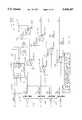
- FIGS. 11 and 12illustrate exemplary circuitry for the input/output printed circuit board 562.
- FIG. 11shows the circuitry connected to the X and Y axis conductive strips of the signature pad 520.
- transistors 24-Q2, 24-Q5 and 24-Q6are turned on to apply a potential of five volts analog, (+5A), through transistor 24-Q2 to the Y+ conductor 2410 which leads to the Y axis strip at one end of the inner resistive surface.
- the return path from the other end of the inner resistive stripis via Y--conductor 2411 and transistor 24-Q6, creating a potential distribution along the long X-axis dimension of the pad.
- the X-axis potential value at the point contacting the outer resistive sheetis coupled via conductors 2412 and 2413 to the channel one input of analog to digital converter 24-U1 (e.g. type LTC1091).
- transistors 24-Q3, 24-Q4 and 24-Q1are turned on, and the Y-axis potential at the contact point is read out via the inner resistive sheet and conductors 2410 and 2414 leading to the channel zero input of the analog to digital converter 24-U1.
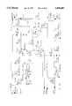
- line 2511receives battery voltage MBATS from the terminal 10.
- Line 2511is coupled with pin 15 of connector 528, via position 15 of receptacle 559, FIG. 21.
- the I/O printed circuit board 562connects position 15 of the header receiving receptacle 559 with position 15 of the header for receptacle 560.
- Line 2511connects with line 2416, FIG. 11, and connects to the CPU printed circuit board 570 via mating interboard connectors such as 573, 574, FIG. 8, a capacitor (not shown, 0.01 microfarad, 50 volts), being connected between MBATS and ground in parallel with 25-TZ1.
- Applying EXT EN to conductor 2512serves to transmit a reset signal to the processor of board 570 via 25-Q7, 25-Q10, 25-Q9 and 2513 (RESET).
- the interboard connectors on board 562such as 573, FIG. 8, are designated J3 and J4 carry the following signals.
- TXDPin 13 (TXD) of CPU 26-U5 connects via line 2610 (RXD3) with the circuit of FIG. 14, which in turn drives line 2611 (RXD4).
- MBATS line 2612also connects with FIG. 14.
- Line 2614connects with the circuit of FIG. 15.
- Pins of CPU 26-U5designated AD7-AD0, respectively connect with data bus 2910, FIG. 16.
- the pin of 26-U5 designated ALEconnects with latch 29-U2 and EPROM 29-U3 via line 2620.
- Pin 32 of 26-U5(PSEN) connects via line 2621 with 29-U3.
- Address bus 2630 from pins designated A8-A15 of 26-U5connects with components 29-U3 and 29-U4 (a CMOS static random access memory, e.g., 128K ⁇ 8).
- Pin RD of CPU 26-U5connects via line 2631, pin RAMEN connects via line 2632; and pin WR connects via line 2633, with 29-U4.
- a signature padmay have the configuration for interfitting in a receptacle.
- the printed circuit boards 562 and 570could be consolidated into a single printed circuit board underlying the signature pad and having comparable dimensions, e.g. about two inches by three inches.
- the inputs and Outputs from the consolidated circuit boardcould comprise MBATS, GND, EXT EN, and the communication lines for two-way alternate point-to-point communication. These inputs and outputs could couple with a module at a region using mating surface contacts.
- signatures as digitized by means of the signature pad modulecould be transferred under the control of a processor module to a data storage card inserted in a slot.
- Alignment pegssuch as 563, 564, FIG. 7, could form part of the signature pad module, such that a touch screen would be accessible to activate the signature pad module by transmitting EXT EN to the pad module in response to actuation of a region of the touch screen in signature capture mode.
- touch screenwould then signal when a signature had been properly digitized and stored.
- the touch screen associated with the modulecan accommodate the entire data capture command set.
- the receiving module 3010may perform the functions of data entry terminal 510, FIG. 6, and may provide battery means 3002 capable of providing for battery operation of the circuitry of FIGS. 11-16.
- receiving module 3010would have coupling means for automatically engaging with the connection means 3001 as module 3000 is inserted into a receptacle 3011 of module 3010.
- the coupling means and connection means 3001could also provide automatically completed signal communication paths such as provided by the terminal connector automatically mating with connector 528, FIG. 10, during assembly of parts 510 and 516, FIG. 6.
- the module 3010may have ledges such as 3012 for overlying the side edges of the module 3000, and may include segmental spherical detents such as 3014 which are spring urged into receptacle 3011 to retain the module 3000 therein.
- a notch 3015may facilitate removal of the complete module 3000 as a unit from the receptacle 3011.
- Module 3000may include a digitizer input screen 3025 over substantially its entire length and width as viewed in FIG. 17, and a graphic display e.g. of the dot matrix type may underlie the digitizer screen and have a resolution sufficient to accurately display handwritten data such as signatures and the like, as well as indicia such as 3022, 3023, and 3024.
- a digitizer input screen 3025over substantially its entire length and width as viewed in FIG. 17, and a graphic display e.g. of the dot matrix type may underlie the digitizer screen and have a resolution sufficient to accurately display handwritten data such as signatures and the like, as well as indicia such as 3022, 3023, and 3024.
- the display means of module 3000may display the mode at 3028 and suitable instructions at 3029.
- the formmay have printed thereon indicia such as 3022, 3023, 3024, "start", and 3029
- indiciasuch as 3022, 3023, 3024, "start", and 3029
- a conventional ball point penmay be used to enter the signature on the form, and to apply a corresponding impression to the digitizer input screen 3025 of FIG. 17.
- the processor of module 3000 or a processor 3042 of module 3010may carry out a comparison of the signature impression 3041 with the stored authorized signatures. If there is a sufficient match with an authorized signature the graphical display may indicate that the signature was a valid authorized signature as at 3044, FIG. 18.
- the matching authorized signature of recordmay be displayed in space 3045, FIG. 18, or the name represented by the signature may be simply printed in space 3045.
- a transaction numbermay be assigned as indicated at 3046.
- the signature 3047 corresponding to impression 3041, as stored by module 3000, module 3010 or storage card 3040may be displayed at a region 3049 adjacent region 3045 so that the operator can confirm the matching condition, or actually make the decision as to whether the signature is to be accepted.
- the signature as enteredmay be stored in fully digitized form or in a suitably compacted form in module 3000, module 3010 or storage card 3049.
- Example VIIIcould be applied to the embodiment of FIGS. 6-16 as a further example, in which case the resistive type digitizer screen 520 could be used for the direct entry of a signature e.g. using a passive wooden stylus, and display 514 could provide a resultant display such as indicated in FIG. 18, and could display indicia such as 3028 and 3029, prior to entry of the signature impression 3041.
- the signature comparison program, and the set of authorized signaturescould then be downloaded into the data terminal 510, e.g. via connectors 534 and 528 from a data storage system within a delivery vehicle or the like.
- U.S. Pat. No. 4,798,919which teaches using the sensing of pressure applied across the signature as a further parameter for use in signature verification.
- computerized processing module 3000provides for the computerized processing and storage of data as described in detail in reference to FIGS. 6-16.
- the stored datae.g. complete digitized information concerning a signature impression 3041 may be transmitted from random access storage such as indicated at 29-U4 via connection means 3001 to an external receiving module such as 3010 or 510, FIG. 6.
- the computerized processing module 3000could be of size to fit in a shirt pocket as with module 516, FIG. 6, e.g. a cross sectional perimeter of not more than about eight inches and a length dimension of not more than about five inches.
- connection means 3001 of module 3000automatically engages with the coupling means in receptacle 3011 as the module 3000 is inserted over detents 3014 and under ledges 3012 to assemble the module 3000 with the receiving module 3010.
- the connection means 3001is automatically disengaged from the coupling means as the module 3000 is removed as a unit from receptacle 3011 (e.g. with the use of one finger inserted into notch 3015).
- the digitizer input screen 3025is transparent so that the matrix type display there beneath is visible to the user through the digitizer screen. Any of the digitizer technologies currently available such as those referred to herein may be utilized. Both the digitizer input and the graphical display of module 3000 have a resolution to accurately record and display handwritten characters such as represented by signatures 3041, 3045 and 3047.
- the datasuch as signatures stored in module 3000 in complete digitized form or in compacted form may be transmitted to the coupling means of receiving module 3010 for utilization externally of module 3000.
- receiving module 3010may have a programmed processor at 3042 for comparing a signature impression data relating to a signature impression 3041 with a set of authorized signatures stored on a data storage card 3040.
- the display of module 3000may display indicia such as 3022, 3023, and 3024 for facilitating input of a signature impression such as 3041 directly on the digitizer input screen 3025, or a form may be located e.g. by pegs 3030, 3031 and itself have indicia printed thereon.
- a conventional display screen at 514, FIG. 6, of a receiving module 510may display instructions adjacent a digitizer screen at 520, and may provide a display such as indicated in FIG. 18, once a signature impression at 520 has been compared with a set of authorized signatures stored by the receiving module 510, FIG. 6.
Landscapes
- Engineering & Computer Science (AREA)
- Physics & Mathematics (AREA)
- Electromagnetism (AREA)
- Theoretical Computer Science (AREA)
- General Physics & Mathematics (AREA)
- General Health & Medical Sciences (AREA)
- Toxicology (AREA)
- Artificial Intelligence (AREA)
- Computer Vision & Pattern Recognition (AREA)
- Health & Medical Sciences (AREA)
- General Engineering & Computer Science (AREA)
- Computer Networks & Wireless Communication (AREA)
- Computer Hardware Design (AREA)
- Human Computer Interaction (AREA)
- Calculators And Similar Devices (AREA)
Abstract
Description
______________________________________Connector 528Connector 534______________________________________J1 1TXD J2 1TXD OutJ1 2DTR J2 2DTRJ1 3RTS J2 3RTSJ1 4RCT J2 4RCTJ1 5RXD J2 5 RXD INJ1 6CTS J2 6CTSJ1 7DSR J2 7DSRJ1 8 CHG InJ2 8 CHG InJ1 9GND J2 9GNDJ1 10 XOVER/TXL J2 10 XOVER/TXLJ1 11 PROX/RXC J2 11 PROX/RXCJ1 12 SCAN/PWR J2 12 SCAN/PWRJ1 13EXT EN J2 13 N.U.J1 14 RCR/CD J2 14 RCR/CDJ1 15MBATS J2 15MBATSJ1 16 N.U.J2 16 N.U.______________________________________
______________________________________J3 1 N.U.J4 1ADCSJ3 2 DI/O J4 2RDX4J3 3ADCLK J4 3TXD3J3 4 JY-J4 4RESETJ3 5JY+ J4 5GNDJ3 6 JX-J4 6 +5VJ3 7JX+ J4 7 MBATS______________________________________
______________________________________CPU (Type 80C31) CPU Pin PinDesignation______________________________________P3 1 N.U.P3 2 DI/9 9 P 1.7P3 3 ADCLK 6 P 1.4P3 4 JY- 5 P 1.3P3 5 JY+ 4 P 1.2P3 6 JX- 3 P 1.1P3 7 JX+ 2 P 1.0P4 1 ADCS 8 P 1.6P4 3TXD3 11RXDP4 4RESET 10RSTP4 522,35 VSS, GND EAPR 6 +5V 44 VCC______________________________________
Claims (13)
Priority Applications (6)
| Application Number | Priority Date | Filing Date | Title |
|---|---|---|---|
| US08/306,073US5598487A (en) | 1986-08-15 | 1994-09-14 | Hand-held data entry system removable signature pad |
| US09/135,771US6621942B1 (en) | 1989-09-29 | 1998-08-18 | Data capture apparatus with handwritten data receiving component |
| US10/085,468US7120319B2 (en) | 1986-08-15 | 2002-02-28 | Data capture apparatus with handwritten data receiving component |
| US10/663,453US20040165793A1 (en) | 1989-09-29 | 2003-09-16 | Apparatus and method for collection of handwritten data |
| US11/352,440US7336853B2 (en) | 1989-09-29 | 2006-02-08 | Apparatus and method for collection of handwritten data |
| US11/475,472US7646941B2 (en) | 1986-08-15 | 2006-06-27 | Data capture apparatus with handwritten data receiving component |
Applications Claiming Priority (7)
| Application Number | Priority Date | Filing Date | Title |
|---|---|---|---|
| US89754786A | 1986-08-15 | 1986-08-15 | |
| US14392188A | 1988-01-14 | 1988-01-14 | |
| US07/415,169US5123064A (en) | 1989-09-29 | 1989-09-29 | Hand-held data entry system and removable signature pad module therefor |
| US07/451,322US5227614A (en) | 1986-08-15 | 1989-12-15 | Core computer processor module, and peripheral shell module assembled to form a pocket size data capture unit |
| US85248092A | 1992-03-17 | 1992-03-17 | |
| US27509694A | 1994-07-14 | 1994-07-14 | |
| US08/306,073US5598487A (en) | 1986-08-15 | 1994-09-14 | Hand-held data entry system removable signature pad |
Related Parent Applications (1)
| Application Number | Title | Priority Date | Filing Date |
|---|---|---|---|
| US27509694AContinuation | 1986-08-15 | 1994-07-14 |
Related Child Applications (1)
| Application Number | Title | Priority Date | Filing Date |
|---|---|---|---|
| US79032897AContinuation | 1986-08-15 | 1997-01-28 |
Publications (1)
| Publication Number | Publication Date |
|---|---|
| US5598487Atrue US5598487A (en) | 1997-01-28 |
Family
ID=27558285
Family Applications (1)
| Application Number | Title | Priority Date | Filing Date |
|---|---|---|---|
| US08/306,073Expired - LifetimeUS5598487A (en) | 1986-08-15 | 1994-09-14 | Hand-held data entry system removable signature pad |
Country Status (1)
| Country | Link |
|---|---|
| US (1) | US5598487A (en) |
Cited By (44)
| Publication number | Priority date | Publication date | Assignee | Title |
|---|---|---|---|---|
| US5826240A (en)* | 1996-01-18 | 1998-10-20 | Rosefaire Development, Ltd. | Sales presentation system for coaching sellers to describe specific features and benefits of a product or service based on input from a prospect |
| USD402572S (en) | 1997-10-24 | 1998-12-15 | Daewoo Telecom Ltd. | Portable navigation assistant |
| US5889506A (en)* | 1996-10-25 | 1999-03-30 | Matsushita Electric Industrial Co., Ltd. | Video user's environment |
| US5974161A (en)* | 1996-03-01 | 1999-10-26 | Hewlett-Packard Company | Detachable card for capturing graphics |
| EP0947909A3 (en)* | 1998-03-27 | 2000-01-12 | International Business Machines Corporation | Flexibly interfaceable portable computing device |
| US6031524A (en)* | 1995-06-07 | 2000-02-29 | Intermec Ip Corp. | Hand-held portable data terminal having removably interchangeable, washable, user-replaceable components with liquid-impervious seal |
| US6046732A (en)* | 1997-12-18 | 2000-04-04 | Mitsubishi Denki Kabushiki Kaisha | Method of allowing users to enter characters into electronic equipment by using cursor key and displaying user-entered characters |
| US6101087A (en)* | 1997-06-19 | 2000-08-08 | Xplore Technologies, Inc. | Portable pen-based computer and auxiliary unit for use with a vehicular docking station |
| US6125356A (en)* | 1996-01-18 | 2000-09-26 | Rosefaire Development, Ltd. | Portable sales presentation system with selective scripted seller prompts |
| WO2000070565A1 (en)* | 1999-05-14 | 2000-11-23 | Identcom Gmbh | Mobile data acquisition device for processing deliveries |
| EP1061433A3 (en)* | 1998-03-27 | 2001-04-04 | International Business Machines Corporation | Flexibly interfaceable portable computing device |
| US20020152386A1 (en)* | 2000-02-11 | 2002-10-17 | De La Puente Arrate Fernando | External signature device for a pc with optical data input via the monitor |
| US6469689B1 (en)* | 1998-08-07 | 2002-10-22 | Hewlett-Packard Company | Appliance and method of using same having a capability to graphically associate and disassociate data with and from one another |
| US6550683B1 (en) | 2000-02-24 | 2003-04-22 | Telxon Corporation | Hand held portable device with multiple functions |
| US20040160442A1 (en)* | 1990-01-19 | 2004-08-19 | Tomoshi Hirayama | Information processing apparatus |
| US20050152340A1 (en)* | 1997-09-16 | 2005-07-14 | Voit Eric A. | Network session management |
| USD508902S1 (en)* | 2004-02-18 | 2005-08-30 | Asia Optical Co., Ltd. | Mobile phone having rotatable camera |
| US20060085250A1 (en)* | 1999-05-11 | 2006-04-20 | Christopher Kantarjiev | Techniques for processing customer service transactions at customer site using mobile computing device |
| US20060095217A1 (en)* | 2004-11-01 | 2006-05-04 | Rosemount Inc. | Magnetic flowmeter with built-in simulator |
| US20060097985A1 (en)* | 2004-11-08 | 2006-05-11 | Samsung Electronics Co., Ltd. | Portable terminal and data input method therefor |
| US20060214284A1 (en)* | 2005-03-24 | 2006-09-28 | Stuart Haden | Apparatus and method for data capture |
| US7120319B2 (en) | 1986-08-15 | 2006-10-10 | Broadcom Corporation | Data capture apparatus with handwritten data receiving component |
| US20070016463A1 (en)* | 2000-11-09 | 2007-01-18 | Borders Louis H | Scheduling delivery of products via the Internet |
| US20070055580A1 (en)* | 2001-03-19 | 2007-03-08 | Woodward Franklin G | Method and apparatus for facilitating online purchase of regulated products over a data network |
| US20070112647A1 (en)* | 1999-05-11 | 2007-05-17 | Borders Louis H | Webstore supporting multiple merchants |
| US20080298875A1 (en)* | 2007-06-01 | 2008-12-04 | Intermec Technologies Corporation | Modular workboard thermal printer system |
| US20090022147A1 (en)* | 1996-04-18 | 2009-01-22 | Farris Robert D | Telephony communication via varied redundant networks |
| US20090094085A1 (en)* | 1999-05-11 | 2009-04-09 | Christopher Angel Kantarjiev | Scheduling delivery of products via the internet |
| US20090164570A1 (en)* | 2000-11-10 | 2009-06-25 | Narasimha Rao Paila | Data transmission and rendering techniques implemented over a client-server system |
| US7664097B2 (en) | 1996-04-18 | 2010-02-16 | Verizon Services Corp. | Telephone service via networking |
| US20100241269A1 (en)* | 1999-05-11 | 2010-09-23 | Peter Ham | Inventory replication based upon order fulfillment rates |
| US7813332B1 (en) | 1997-03-19 | 2010-10-12 | Verizon Services Corp. | Voice call alternative routing through PSTN and internet networks |
| US7817619B1 (en) | 1996-12-18 | 2010-10-19 | Verizon Services Corp. | Internet long distance telephone service |
| US7830860B2 (en) | 1997-03-11 | 2010-11-09 | Verizon Services Corp. | Packet data network voice call quality monitoring |
| US7835344B1 (en) | 1997-03-19 | 2010-11-16 | Verizon Services Corp. | Transport of caller identification information through diverse communication networks |
| US8090626B1 (en) | 2000-12-27 | 2012-01-03 | Ipventure, Inc. | Item substitution for unavailable items relating to a customer order |
| US8938062B2 (en) | 1995-12-11 | 2015-01-20 | Comcast Ip Holdings I, Llc | Method for accessing service resource items that are for use in a telecommunications system |
| US9191505B2 (en) | 2009-05-28 | 2015-11-17 | Comcast Cable Communications, Llc | Stateful home phone service |
| US20160321214A1 (en)* | 2015-04-28 | 2016-11-03 | Adobe Systems Incorporated | Capturing electronic signatures using an expanded interface area |
| US9621229B2 (en) | 2014-04-07 | 2017-04-11 | Google, Inc. | Systems for enabling chassis-coupled modular mobile electronic devices |
| US9717045B2 (en) | 2014-04-07 | 2017-07-25 | Google Inc. | Systems for enabling modular mobile electronic devices |
| US10083163B2 (en) | 2016-08-10 | 2018-09-25 | Adobe Systems Incorporated | Completing fields in electronic documents by automatically assigning drawing input |
| US10084896B1 (en) | 2015-11-05 | 2018-09-25 | Google Llc | Modular electronic devices |
| US10209817B1 (en) | 2015-11-05 | 2019-02-19 | Google Llc | Modular electronic devices |
Citations (10)
| Publication number | Priority date | Publication date | Assignee | Title |
|---|---|---|---|---|
| US4005400A (en)* | 1974-04-30 | 1977-01-25 | Societe Suisse Pour L'industrie Horologere Management Services S.A. | Data entry and decoding system for scripted data |
| US4158194A (en)* | 1976-12-27 | 1979-06-12 | Recognition Equipment Incorporated | Optical recognition system |
| US4718103A (en)* | 1985-10-08 | 1988-01-05 | Hitachi, Ltd. | Method and apparatus for on-line recognizing handwritten patterns |
| US4752965A (en)* | 1984-02-24 | 1988-06-21 | The De La Rue Company Plc | Sign verification |
| US4866646A (en)* | 1986-05-26 | 1989-09-12 | Kabushiki Kaisha Toshiba | Handheld data input apparatus |
| US5012349A (en)* | 1986-10-06 | 1991-04-30 | Fay Stefan G De | Method and portable device for detection, storage and for eventual processing and reproduction of graphic symbols appearing on any type of carrier |
| US5049862A (en)* | 1989-10-06 | 1991-09-17 | Communication Intelligence Corporation ("Cic") | Keyless flat panel portable computer--computer aided notebook |
| US5123064A (en)* | 1989-09-29 | 1992-06-16 | Norand Corporation | Hand-held data entry system and removable signature pad module therefor |
| US5194852A (en)* | 1986-12-01 | 1993-03-16 | More Edward S | Electro-optic slate for direct entry and display and/or storage of hand-entered textual and graphic information |
| US5227614A (en)* | 1986-08-15 | 1993-07-13 | Norand Corporation | Core computer processor module, and peripheral shell module assembled to form a pocket size data capture unit |
- 1994
- 1994-09-14USUS08/306,073patent/US5598487A/ennot_activeExpired - Lifetime
Patent Citations (10)
| Publication number | Priority date | Publication date | Assignee | Title |
|---|---|---|---|---|
| US4005400A (en)* | 1974-04-30 | 1977-01-25 | Societe Suisse Pour L'industrie Horologere Management Services S.A. | Data entry and decoding system for scripted data |
| US4158194A (en)* | 1976-12-27 | 1979-06-12 | Recognition Equipment Incorporated | Optical recognition system |
| US4752965A (en)* | 1984-02-24 | 1988-06-21 | The De La Rue Company Plc | Sign verification |
| US4718103A (en)* | 1985-10-08 | 1988-01-05 | Hitachi, Ltd. | Method and apparatus for on-line recognizing handwritten patterns |
| US4866646A (en)* | 1986-05-26 | 1989-09-12 | Kabushiki Kaisha Toshiba | Handheld data input apparatus |
| US5227614A (en)* | 1986-08-15 | 1993-07-13 | Norand Corporation | Core computer processor module, and peripheral shell module assembled to form a pocket size data capture unit |
| US5012349A (en)* | 1986-10-06 | 1991-04-30 | Fay Stefan G De | Method and portable device for detection, storage and for eventual processing and reproduction of graphic symbols appearing on any type of carrier |
| US5194852A (en)* | 1986-12-01 | 1993-03-16 | More Edward S | Electro-optic slate for direct entry and display and/or storage of hand-entered textual and graphic information |
| US5123064A (en)* | 1989-09-29 | 1992-06-16 | Norand Corporation | Hand-held data entry system and removable signature pad module therefor |
| US5049862A (en)* | 1989-10-06 | 1991-09-17 | Communication Intelligence Corporation ("Cic") | Keyless flat panel portable computer--computer aided notebook |
Cited By (93)
| Publication number | Priority date | Publication date | Assignee | Title |
|---|---|---|---|---|
| US7646941B2 (en) | 1986-08-15 | 2010-01-12 | Broadcom Corporation | Data capture apparatus with handwritten data receiving component |
| US20070065046A1 (en)* | 1986-08-15 | 2007-03-22 | Hacker David C | Data capture apparatus with handwritten data receiving component |
| US7120319B2 (en) | 1986-08-15 | 2006-10-10 | Broadcom Corporation | Data capture apparatus with handwritten data receiving component |
| US7742039B2 (en)* | 1990-01-19 | 2010-06-22 | Sony Corporation | Information processing apparatus |
| US20070089046A1 (en)* | 1990-01-19 | 2007-04-19 | Tomoshi Hirayama | Information processing apparatus |
| US7176922B2 (en)* | 1990-01-19 | 2007-02-13 | Sony Corporation | Information processing apparatus |
| US20040160442A1 (en)* | 1990-01-19 | 2004-08-19 | Tomoshi Hirayama | Information processing apparatus |
| US6031524A (en)* | 1995-06-07 | 2000-02-29 | Intermec Ip Corp. | Hand-held portable data terminal having removably interchangeable, washable, user-replaceable components with liquid-impervious seal |
| US8938062B2 (en) | 1995-12-11 | 2015-01-20 | Comcast Ip Holdings I, Llc | Method for accessing service resource items that are for use in a telecommunications system |
| US6125356A (en)* | 1996-01-18 | 2000-09-26 | Rosefaire Development, Ltd. | Portable sales presentation system with selective scripted seller prompts |
| US5826240A (en)* | 1996-01-18 | 1998-10-20 | Rosefaire Development, Ltd. | Sales presentation system for coaching sellers to describe specific features and benefits of a product or service based on input from a prospect |
| US5974161A (en)* | 1996-03-01 | 1999-10-26 | Hewlett-Packard Company | Detachable card for capturing graphics |
| US20090022147A1 (en)* | 1996-04-18 | 2009-01-22 | Farris Robert D | Telephony communication via varied redundant networks |
| US7483417B2 (en) | 1996-04-18 | 2009-01-27 | Verizon Services Corp. | Telephony communication via varied redundant networks |
| US8379531B2 (en) | 1996-04-18 | 2013-02-19 | Verizon Services Corp. | Telephony communication via varied redundant networks |
| US7664097B2 (en) | 1996-04-18 | 2010-02-16 | Verizon Services Corp. | Telephone service via networking |
| US8553681B2 (en) | 1996-06-26 | 2013-10-08 | Verizon Services Corp. | Telephone service via packet-switched networking |
| US5889506A (en)* | 1996-10-25 | 1999-03-30 | Matsushita Electric Industrial Co., Ltd. | Video user's environment |
| US7817619B1 (en) | 1996-12-18 | 2010-10-19 | Verizon Services Corp. | Internet long distance telephone service |
| US7830860B2 (en) | 1997-03-11 | 2010-11-09 | Verizon Services Corp. | Packet data network voice call quality monitoring |
| US7835344B1 (en) | 1997-03-19 | 2010-11-16 | Verizon Services Corp. | Transport of caller identification information through diverse communication networks |
| US7813332B1 (en) | 1997-03-19 | 2010-10-12 | Verizon Services Corp. | Voice call alternative routing through PSTN and internet networks |
| US6101087A (en)* | 1997-06-19 | 2000-08-08 | Xplore Technologies, Inc. | Portable pen-based computer and auxiliary unit for use with a vehicular docking station |
| US20050152340A1 (en)* | 1997-09-16 | 2005-07-14 | Voit Eric A. | Network session management |
| US7948968B2 (en) | 1997-09-16 | 2011-05-24 | Verizon Communications Inc. | Network session management |
| US9215254B1 (en) | 1997-09-16 | 2015-12-15 | Verizon Patent And Licensing Inc. | Network session management for telephony over hybrid networks |
| US8976782B1 (en) | 1997-09-16 | 2015-03-10 | Verizon Patent And Licensing Inc. | Network session management for telephony over hybrid networks |
| USD402572S (en) | 1997-10-24 | 1998-12-15 | Daewoo Telecom Ltd. | Portable navigation assistant |
| US6046732A (en)* | 1997-12-18 | 2000-04-04 | Mitsubishi Denki Kabushiki Kaisha | Method of allowing users to enter characters into electronic equipment by using cursor key and displaying user-entered characters |
| US6727894B1 (en) | 1998-03-27 | 2004-04-27 | International Business Machines Corporation | Flexibly interfaceable portable computing device |
| EP0947909A3 (en)* | 1998-03-27 | 2000-01-12 | International Business Machines Corporation | Flexibly interfaceable portable computing device |
| EP1061433A3 (en)* | 1998-03-27 | 2001-04-04 | International Business Machines Corporation | Flexibly interfaceable portable computing device |
| US6628267B2 (en) | 1998-03-27 | 2003-09-30 | International Business Machines Corporation | Flexibly interfaceable portable computing device |
| US6362440B1 (en) | 1998-03-27 | 2002-03-26 | International Business Machines Corporation | Flexibly interfaceable portable computing device |
| US6469689B1 (en)* | 1998-08-07 | 2002-10-22 | Hewlett-Packard Company | Appliance and method of using same having a capability to graphically associate and disassociate data with and from one another |
| US8626333B2 (en) | 1999-05-11 | 2014-01-07 | Ipventure, Inc. | Method and system for order fulfillment in a distribution center |
| US9396451B2 (en) | 1999-05-11 | 2016-07-19 | June Ray Limited | Method and system for order fulfillment in a distribution center |
| US20080015959A1 (en)* | 1999-05-11 | 2008-01-17 | Andre Kruglikov | Real-time display of available products over the Internet |
| US20090094085A1 (en)* | 1999-05-11 | 2009-04-09 | Christopher Angel Kantarjiev | Scheduling delivery of products via the internet |
| US20090150534A1 (en)* | 1999-05-11 | 2009-06-11 | Andrew Karl Miller | Load balancing technique implemented in a data network device utilizing a data cache |
| US8635113B2 (en) | 1999-05-11 | 2014-01-21 | Ipventure, Inc. | Integrated online store |
| US20090222129A1 (en)* | 1999-05-11 | 2009-09-03 | William Henry Waddington | Mothod and system for order fulfullment in a distribution center |
| US20070174144A1 (en)* | 1999-05-11 | 2007-07-26 | Borders Louis H | Online store product availability |
| US20070162353A1 (en)* | 1999-05-11 | 2007-07-12 | Borders Louis H | Online store using common carrier |
| US8326708B2 (en) | 1999-05-11 | 2012-12-04 | Ipventure, Inc. | Techniques for processing customer service transactions at customer site using mobile computing device |
| US7792712B2 (en) | 1999-05-11 | 2010-09-07 | Ipventure, Inc. | Techniques for processing customer service transactions at customer site using mobile computing device |
| US9865010B2 (en) | 1999-05-11 | 2018-01-09 | June Ray Limited | Online store product availability |
| US20100241269A1 (en)* | 1999-05-11 | 2010-09-23 | Peter Ham | Inventory replication based upon order fulfillment rates |
| US20070112647A1 (en)* | 1999-05-11 | 2007-05-17 | Borders Louis H | Webstore supporting multiple merchants |
| US9697547B2 (en) | 1999-05-11 | 2017-07-04 | June Ray Limited | Integrated online store |
| US8170915B2 (en) | 1999-05-11 | 2012-05-01 | Ipventure, Inc. | Online store product availability |
| US8140183B2 (en) | 1999-05-11 | 2012-03-20 | Ipventure, Inc. | Method and system for order fulfillment in a distribution center |
| US20060085250A1 (en)* | 1999-05-11 | 2006-04-20 | Christopher Kantarjiev | Techniques for processing customer service transactions at customer site using mobile computing device |
| US20100332402A1 (en)* | 1999-05-11 | 2010-12-30 | Christopher Kantarjiev | Techniques for processing customer service transactions at customer site using mobile computing device |
| US8600821B2 (en) | 1999-05-11 | 2013-12-03 | Ipventure, Inc. | Webstore supporting multiple merchants |
| US7904975B2 (en) | 1999-05-11 | 2011-03-15 | Ipventure, Inc. | Real-time display of available products over the internet |
| US7930416B2 (en) | 1999-05-11 | 2011-04-19 | Ipventure, Inc. | Load balancing technique implemented in a data network device utilizing a data cache |
| US9342808B2 (en) | 1999-05-11 | 2016-05-17 | June Ray Limited | Load balancing technique implemented in a data network device utilizing a data cache |
| US20110173090A1 (en)* | 1999-05-11 | 2011-07-14 | Andrew Karl Miller | Load balancing technique implemented in a data network device utilizing a data cache |
| WO2000070565A1 (en)* | 1999-05-14 | 2000-11-23 | Identcom Gmbh | Mobile data acquisition device for processing deliveries |
| US20020152386A1 (en)* | 2000-02-11 | 2002-10-17 | De La Puente Arrate Fernando | External signature device for a pc with optical data input via the monitor |
| US6550683B1 (en) | 2000-02-24 | 2003-04-22 | Telxon Corporation | Hand held portable device with multiple functions |
| US9413808B2 (en) | 2000-05-10 | 2016-08-09 | June Ray Limited | Data transmission and rendering techniques by a device via a network |
| US10091335B2 (en) | 2000-05-10 | 2018-10-02 | June Ray Limited | Data transmission and rendering techniques by a device via a network |
| US20070016463A1 (en)* | 2000-11-09 | 2007-01-18 | Borders Louis H | Scheduling delivery of products via the Internet |
| US7853870B2 (en) | 2000-11-10 | 2010-12-14 | Narasimha Rao Paila | Data transmission and rendering techniques implemented over a client-server system |
| US8601365B2 (en) | 2000-11-10 | 2013-12-03 | Ipventure, Inc. | Data transmission and rendering techniques implemented over a client-server system |
| US20110047210A1 (en)* | 2000-11-10 | 2011-02-24 | Narasimha Rao Paila | Data transmission and rendering techniques implemented over a client-server system |
| US20090164570A1 (en)* | 2000-11-10 | 2009-06-25 | Narasimha Rao Paila | Data transmission and rendering techniques implemented over a client-server system |
| US8090626B1 (en) | 2000-12-27 | 2012-01-03 | Ipventure, Inc. | Item substitution for unavailable items relating to a customer order |
| US8751334B2 (en) | 2000-12-27 | 2014-06-10 | Ipventure, Inc. | Item substitution for unavailable items relating to a customer order |
| US20070055580A1 (en)* | 2001-03-19 | 2007-03-08 | Woodward Franklin G | Method and apparatus for facilitating online purchase of regulated products over a data network |
| US8880428B2 (en) | 2001-03-19 | 2014-11-04 | Ipventure, Inc. | Restricted purchase of regulated items over a network |
| US20070136149A1 (en)* | 2001-03-19 | 2007-06-14 | Woodward Franklin G | Restricted purchase of regulated items over a network |
| US8010411B2 (en) | 2001-03-19 | 2011-08-30 | Ipventure, Inc. | Restricted purchase of regulated items over a network |
| US7801772B2 (en) | 2001-03-19 | 2010-09-21 | Ip Venture, Inc. | Method and apparatus for facilitating online purchase of regulated products over a data network |
| USD508902S1 (en)* | 2004-02-18 | 2005-08-30 | Asia Optical Co., Ltd. | Mobile phone having rotatable camera |
| US20060095217A1 (en)* | 2004-11-01 | 2006-05-04 | Rosemount Inc. | Magnetic flowmeter with built-in simulator |
| US8311370B2 (en)* | 2004-11-08 | 2012-11-13 | Samsung Electronics Co., Ltd | Portable terminal and data input method therefor |
| US20060097985A1 (en)* | 2004-11-08 | 2006-05-11 | Samsung Electronics Co., Ltd. | Portable terminal and data input method therefor |
| US20060214284A1 (en)* | 2005-03-24 | 2006-09-28 | Stuart Haden | Apparatus and method for data capture |
| US20080298875A1 (en)* | 2007-06-01 | 2008-12-04 | Intermec Technologies Corporation | Modular workboard thermal printer system |
| US9191505B2 (en) | 2009-05-28 | 2015-11-17 | Comcast Cable Communications, Llc | Stateful home phone service |
| US9621229B2 (en) | 2014-04-07 | 2017-04-11 | Google, Inc. | Systems for enabling chassis-coupled modular mobile electronic devices |
| US9717045B2 (en) | 2014-04-07 | 2017-07-25 | Google Inc. | Systems for enabling modular mobile electronic devices |
| US9867125B2 (en) | 2014-04-07 | 2018-01-09 | Google Llc | Systems for enabling modular mobile electronic devices |
| US9929778B2 (en) | 2014-04-07 | 2018-03-27 | Google Llc | Systems for enabling chassis-coupled modular mobile electronic devices |
| US20160321214A1 (en)* | 2015-04-28 | 2016-11-03 | Adobe Systems Incorporated | Capturing electronic signatures using an expanded interface area |
| US11132105B2 (en)* | 2015-04-28 | 2021-09-28 | Adobe Inc. | Capturing electronic signatures using an expanded interface area |
| US10084896B1 (en) | 2015-11-05 | 2018-09-25 | Google Llc | Modular electronic devices |
| US10209817B1 (en) | 2015-11-05 | 2019-02-19 | Google Llc | Modular electronic devices |
| US10673996B2 (en) | 2015-11-05 | 2020-06-02 | Google Llc | Modular electronic device |
| US10083163B2 (en) | 2016-08-10 | 2018-09-25 | Adobe Systems Incorporated | Completing fields in electronic documents by automatically assigning drawing input |
Similar Documents
| Publication | Publication Date | Title |
|---|---|---|
| US5598487A (en) | Hand-held data entry system removable signature pad | |
| US7336853B2 (en) | Apparatus and method for collection of handwritten data | |
| US5123064A (en) | Hand-held data entry system and removable signature pad module therefor | |
| US5468947A (en) | Pocket size data capture unit with processor and shell modules | |
| US5227614A (en) | Core computer processor module, and peripheral shell module assembled to form a pocket size data capture unit | |
| US6032866A (en) | Foldable apparatus having an interface | |
| US4377741A (en) | Apparatus for producing updated information on a tangible medium | |
| US5744789A (en) | Bar-code reader | |
| US7121470B2 (en) | Transaction terminal having elongated finger recess | |
| US9734493B2 (en) | Terminal including imaging assembly | |
| US7023692B2 (en) | Multifunctional electronic palmtop computer | |
| US6312175B1 (en) | Integrated keyboard input device | |
| US5579487A (en) | Portable work slate computer with multiple docking positions for interchangeably receiving removable modules | |
| JP5738008B2 (en) | Portable payment terminal | |
| US5019697A (en) | Data collection system using memory card | |
| CN103456110B (en) | There is the check out devices of multi-touch input device | |
| US20030132293A1 (en) | Transaction terminal including raised surface peripheral to touch screen | |
| US20060119577A1 (en) | Electronic book with a built-in card scanner | |
| US20030132294A1 (en) | Transaction terminal including signature entry feedback | |
| JP2001344658A (en) | Bar code reader | |
| TW457446B (en) | Integrated keyboard input device | |
| EP1076879B1 (en) | A unit comprising a card read/write device | |
| TW464823B (en) | Integrated POS input device | |
| JPH03273458A (en) | portable data processing device | |
| JPS6243798A (en) | Product sales data processing device |
Legal Events
| Date | Code | Title | Description |
|---|---|---|---|
| AS | Assignment | Owner name:NORAND CORPORATION, IOWA Free format text:ASSIGNMENT OF ASSIGNORS INTEREST;ASSIGNORS:DANIELSON, ARVIN D.;WALTER, JERRY L.;DURBIN, DENNIS A.;AND OTHERS;REEL/FRAME:008182/0339;SIGNING DATES FROM 19920507 TO 19920608 | |
| STCF | Information on status: patent grant | Free format text:PATENTED CASE | |
| FEPP | Fee payment procedure | Free format text:PAYOR NUMBER ASSIGNED (ORIGINAL EVENT CODE: ASPN); ENTITY STATUS OF PATENT OWNER: LARGE ENTITY | |
| FPAY | Fee payment | Year of fee payment:4 | |
| FPAY | Fee payment | Year of fee payment:8 | |
| AS | Assignment | Owner name:INTERMEC TECHNOLOGIES CORPORATION, WASHINGTON Free format text:MERGER;ASSIGNOR:NORAND CORPORATION;REEL/FRAME:015766/0590 Effective date:19971216 Owner name:INTERMEC IP CORP., WASHINGTON Free format text:ASSIGNMENT OF ASSIGNORS INTEREST;ASSIGNOR:INTERMEC TECHNOLOGIES CORPORATION;REEL/FRAME:015766/0619 Effective date:19990721 | |
| AS | Assignment | Owner name:INTERMEC TECHNOLOGIES CORPORATION, WASHINGTON Free format text:ASSIGNMENT OF ASSIGNORS INTEREST;ASSIGNOR:INTERMEC IP CORP.;REEL/FRAME:015819/0423 Effective date:20050322 | |
| FPAY | Fee payment | Year of fee payment:12 |