US5598086A - Peak voltage and peak slope detector for a battery charger circuit - Google Patents
Peak voltage and peak slope detector for a battery charger circuitDownload PDFInfo
- Publication number
- US5598086A US5598086AUS08/510,999US51099995AUS5598086AUS 5598086 AUS5598086 AUS 5598086AUS 51099995 AUS51099995 AUS 51099995AUS 5598086 AUS5598086 AUS 5598086A
- Authority
- US
- United States
- Prior art keywords
- voltage
- peak
- counter
- battery
- count
- Prior art date
- Legal status (The legal status is an assumption and is not a legal conclusion. Google has not performed a legal analysis and makes no representation as to the accuracy of the status listed.)
- Expired - Lifetime
Links
- 230000008859changeEffects0.000claimsabstractdescription32
- 238000000034methodMethods0.000claimsdescription17
- 238000005070samplingMethods0.000claimsdescription14
- 230000008569processEffects0.000claimsdescription7
- 230000001360synchronised effectEffects0.000claimsdescription2
- 230000008878couplingEffects0.000claims2
- 238000010168coupling processMethods0.000claims2
- 238000005859coupling reactionMethods0.000claims2
- 238000001514detection methodMethods0.000description29
- 238000010586diagramMethods0.000description14
- 230000007423decreaseEffects0.000description4
- 238000004519manufacturing processMethods0.000description4
- -1Nickel Metal HydrideChemical class0.000description3
- 229910052987metal hydrideInorganic materials0.000description3
- 229910052759nickelInorganic materials0.000description3
- PXHVJJICTQNCMI-UHFFFAOYSA-NnickelSubstances[Ni]PXHVJJICTQNCMI-UHFFFAOYSA-N0.000description3
- OJIJEKBXJYRIBZ-UHFFFAOYSA-Ncadmium nickelChemical compound[Ni].[Cd]OJIJEKBXJYRIBZ-UHFFFAOYSA-N0.000description2
- 230000001413cellular effectEffects0.000description2
- 230000003111delayed effectEffects0.000description2
- 238000012986modificationMethods0.000description2
- 230000004048modificationEffects0.000description2
- 230000009467reductionEffects0.000description2
- 230000008901benefitEffects0.000description1
- 238000006243chemical reactionMethods0.000description1
- 230000000295complement effectEffects0.000description1
- 238000005259measurementMethods0.000description1
- 230000000717retained effectEffects0.000description1
- 230000000630rising effectEffects0.000description1
- 230000035945sensitivityEffects0.000description1
Images


Classifications
- H—ELECTRICITY
- H02—GENERATION; CONVERSION OR DISTRIBUTION OF ELECTRIC POWER
- H02J—CIRCUIT ARRANGEMENTS OR SYSTEMS FOR SUPPLYING OR DISTRIBUTING ELECTRIC POWER; SYSTEMS FOR STORING ELECTRIC ENERGY
- H02J7/00—Circuit arrangements for charging or depolarising batteries or for supplying loads from batteries
- H02J7/007—Regulation of charging or discharging current or voltage
- H02J7/00712—Regulation of charging or discharging current or voltage the cycle being controlled or terminated in response to electric parameters
- H02J7/007182—Regulation of charging or discharging current or voltage the cycle being controlled or terminated in response to electric parameters in response to battery voltage
- H02J7/007184—Regulation of charging or discharging current or voltage the cycle being controlled or terminated in response to electric parameters in response to battery voltage in response to battery voltage gradient
Definitions
- This inventionrelates, in general, to battery charger circuits, and more particularly, to peak voltage and peak slope detector circuits for a battery charger circuit.
- Non-rechargeable batteriesare not cost efficient for electronic systems that are in constant use.
- Rechargeable batteriesare a popular and cost effective alternative to power most types of electronics.
- Many different types of rechargeable batteriesare currently offered such as Alkaline, Nickel-Cadmium (NiCd), and Nickel Metal Hydride (NiMH).
- rechargeable batteriesare recharged by applying a voltage and current for a predetermined time period.
- Different battery typeshave different charging requirements but most can be damaged or have a reduced life when charged improperly.
- a correct charging procedurerequires sensitive circuitry that monitors both battery voltage and current.
- a battery charger circuitis designed to automatically shut off when the batteries being charged are fully charged which maximizes the power delivered by the batteries and the number of times they can be recharged.
- FIG. 1is a prior art peak voltage detector circuit for a battery charger
- FIG. 2is a prior art peak voltage and peak slope detector circuit for a battery charger
- FIG. 3is a graph of two common rechargeable batteries illustrating a charge profile during a battery charging sequence
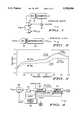
- FIG. 4is a block diagram of a peak voltage and peak slope detection circuit in accordance with the present invention.
- FIG. 5is a timing diagram illustrating the output signals provided by the sample timer of FIG. 4 in accordance with the present invention.
- FIG. 6is a schematic diagram of a sample timer for producing output signals corresponding to FIG. 5;
- FIG. 7is a schematic diagram of a counter comparator for peak voltage detection corresponding to the counter comparator of FIG. 4 in accordance with the present invention.
- FIG. 8is a schematic diagram of a counter comparator for peak slope detection corresponding to the counter comparator of FIG. 4 in accordance with the present invention.
- Charging a rechargeable battery for maximum battery life and power outputrequires a circuit that detects either a peak voltage or a peak slope during a battery charging sequence.
- a charging batteryhas a voltage that increases monotonically until a peak voltage or maximum voltage is attained. Further charging after the peak voltage actually reduces the output voltage of the battery.
- a peak slope of a battery charge profileis an area of the curve where the battery voltage has the greatest rate of voltage change.
- a peak slopeoccurs before a peak voltage during a battery charging sequence.
- Two different schools of thoughtapply when selecting a recharging technique. Charging a battery to a peak voltage insures the battery will deliver maximum power to a load for the longest time period. A peak voltage is detected when a previous sampled voltage is greater than the immediate battery voltage thus a battery charger using peak voltage detection slightly overcharges the battery. Longevity, or the number times a battery can be recharged may be reduced using this technique.
- Peak slope detectioninsures that a battery is not overcharged since it occurs before a peak voltage.
- the rate of change in battery voltage during rechargingis monitored and a peak rate of change detected.
- Peak slope detectionis preferred for lightly loaded batteries that require maximum battery life.
- Original Equipment Manufacturers (OEM) of battery charger circuitsrequire that an integrated circuit be provided that is configurable for either peak voltage or peak slope detection.
- OEMOriginal Equipment Manufacturers
- the sensitivity of a peak voltage or peak slope detector circuitis critical to performance. A detector circuit having high resolution for detecting voltage changes will enhance the power output, the time between recharges, and the recharge life of a battery.
- Another factor in the design of a detector circuitis cost, a detector circuit that is cheaper to manufacture yet provides better performance is very attractive to an OEM of battery chargers.
- FIG. 1is a schematic diagram of a prior art "ratchet” Digital to Analog Converter (DAC) peak voltage detector circuit 11 used in battery charger circuits. Peak voltage detector circuit 11 is limited to peak voltage detection and is not used to detect peak slope. Peak voltage detector circuit 11 comprises a DAC 12, a counter 13, a comparator 14, a comparator 15, and logic circuitry 16.
- DACDigital to Analog Converter
- An input Vinis coupled to a non-inverting input of comparator 14 and an inverting input of offset comparator 15.
- the input Vin of peak voltage detector circuit 11is coupled to a battery or batteries being charged for sensing battery voltage during a battery charging sequence.
- Logic circuitry 16has an input coupled to an output of comparator 14, a clock input coupled for receiving a clock signal, and an output.
- Counter 13has an input coupled to the output of logic circuitry 16 and a plurality of outputs. Counter 13 provides a digital output that incrementally increases DAC 12 via the clock signal.
- DAC 12has a plurality of inputs coupled to the plurality of outputs of counter 13 and an output coupled to an inverting input of comparator 14 and a non-inverting input of offset comparator 15.
- a logic one level provided at an output Vout of offset comparator 15indicates a peak voltage is detected and disables the battery charging sequence.
- a battery charging sequencemonotonically increases a battery voltage until a peak voltage occurs, after which the battery voltage decreases in voltage.
- Peak voltage detector circuit 11compares the battery voltage against a previous sampled battery voltage (provided by DAC 12). A peak voltage is detected when the battery voltage is less than an output voltage of DAC 12. For example, prior to a battery charging sequence counter 13 is reset to a zero count.
- DAC 12outputs zero volts with a zero count digital input from counter 13.
- Comparator 14compares the battery voltage applied to input Vin against the output voltage of DAC 12. If the battery voltage is greater than the output voltage of DAC 12 comparator 14 outputs a logic one level that enables logic circuitry 16 to provide a clock signal to counter 13.
- Counter 13is incremented which increases the output voltage of DAC 12 by a LSB voltage. Comparator 14 and logic circuitry 16 continues to allow clock pulses to increment counter 13 until the output voltage of DAC 12 is greater than the battery voltage. Each clock pulse increases the output voltage of DAC 12 by an LSB voltage. A difference voltage between the battery voltage and the output voltage of DAC 12 is less than or equal to a LSB voltage of DAC 12 when the output voltage of DAC 12 is greater than the battery voltage. If the battery voltage is less than the output voltage of DAC 12, comparator 14 outputs a logic zero level. A logic zero level output by comparator 14 disables logic circuitry 16 from providing a clock signal to counter 13. The output voltage of DAC 12 stays constant until the battery voltage increases greater than the output voltage of DAC 12 due to battery charging.
- Offset comparator 15outputs a logic zero level as the battery voltage rises during the battery charging sequence.
- Offset comparator 15has a built in voltage offset that is greater than an LSB voltage of DAC 12. The offset voltage allows offset comparator 15 to maintain a logic zero level output when the output voltage of DAC 12 is greater than the battery voltage but within a LSB voltage of the battery voltage. During the battery charging sequence the battery voltage will peak at some point and start to fall as the battery is overcharged.
- Offset comparator 15outputs a logic one level when the voltage difference between the output voltage of DAC 12 is greater than the voltage offset of offset comparator 15. The logic one level signifies the battery charging sequence is over.
- peak voltage detect circuit 11is limited by the resolution of DAC 12 and the offset voltage of comparator 15. Utilizing a DAC with a smaller LSB voltage will reduce the amount of overcharging after the peak voltage if the offset voltage of comparator 15 is also reduced. Peak voltage detect circuit 11 is also susceptible to noise coupled to input Vin. A battery charging sequence produces both current and voltage spikes on the battery that can produce false triggering of comparator 14 and offset comparator 15. A filter is sometimes employed at the input Vin to reduce noise problems.
- FIG. 2is a schematic diagram of a prior art microprocessor or microcontroller based peak voltage and peak slope detection circuit 21 for a battery charger.
- Peak voltage and peak slope detection circuit 21comprises an Analog to Digital Converter (ADC) 22 and a microprocessor 23.
- ADC 22converts the analog voltage to a corresponding digital number that is coupled to microprocessor 23.
- a battery voltageis sampled at predetermined time intervals. The sampled voltage values are stored in memory of the microprocessor for analysis.
- Microprocessor 23includes a software program for analyzing the sampled battery voltages to determine either peak voltage or peak slope.
- ADC 22Accuracy of peak voltage and peak slope detection circuit 21 is limited by ADC 22.
- an 8 bit ADCis used which has a resolution of approximately 8 millivolts with a 2 volt full scale voltage.
- An 8 bit ADCis not accurate enough for a rechargeable battery such as a Nickel Metal Hydride battery since it produces smaller voltage changes during a charging sequence when compared to other battery types.
- Increasing the resolution of ADC 22will improve performance of peak voltage and peak slope detection circuit 21 but at a higher cost.
- a 10 bit monotonic (highly linear) ADCwould greatly increase the cost of peak voltage and peak slope detection circuit 21.
- a microprocessor based peak voltage and peak slope detection circuitis inherently more expensive than other corresponding circuits (for example the circuit shown in FIG.
- peak voltage and peak slope detection circuit 21is sensitive to noise introduced during a battery charging sequence. Any noise introduced during a sampling process at input Vin is added to the output of ADC 22.
- a filter(not shown) is typically employed at the input to ADC 22 to remove noise.
- FIG. 3is a graph of a charge profile of two battery types, Nickel Cadmium (Ni--Cd) and Nickel Metal Hydride (Ni--Mh) during a battery charging sequence.
- the graphillustrates battery voltage versus percent charge capacity. Note that a battery can be charged greater than 100 percent capacity. In general, batteries are rated in ampere/hours which is the amount of current the battery can deliver in a defined time period. One hundred percent capacity corresponds to the battery rating listed by the manufacturer. A battery capacity is typically underrated by the manufacturer which allows a battery to be charged to greater than its rating. In other words a battery charged to more than 100 percent capacity will deliver more current than the manufacturers ampere/hour rating.
- Ni--Cd batteriescharge to a higher voltage than Ni--Mh.
- a problem with Ni--Mh batteriesis the smaller rate of change that occurs at a peak voltage and a peak slope.
- a higher resolution circuitis required to detect the voltage changes of a Ni--Mh battery to insure correct charging. Overshooting a peak voltage which may substantially charge a battery greater than 100 percent capacity will produce excess power dissipation within the battery which reduces battery life (the number of times the battery can be recharged).
- the peak voltage of the Ni--Mh batteryoccurs in a relatively flat portion of the curve which could produce a significant overcharging if a peak voltage and peak slope detect circuit cannot resolve small changes in battery voltage.
- a similar casecan be made for a peak slope measurement where the rate of voltage change is small during a battery charging sequence.
- a peak voltage and peak slope detector circuitis disclosed herein that has increased resolution to prevent battery overcharging.
- a resolution of two millivoltsis achieved which greatly reduces overcharging when compared to other systems with less resolution charging Ni--Mh batteries. Higher resolution is easily achieved using the same circuitry if required.
- the peak voltage and peak slope detector circuitalso reduces manufacturing costs by eliminating costly components such as a microprocessor, DAC, or ADC.
- a VFCreceives an input voltage and produces a signal having a frequency that corresponds to the magnitude of the input voltage.
- a battery voltageis sampled for a predetermined time period and the number of pulses from a VFC are counted and compared with a previous sampled battery voltage. Both the peak voltage and the peak slope is accurately detected via this comparison. Resolution is increased by changing the frequency or the sample time period.
- FIG. 4is a block diagram of a peak voltage and peak slope detector circuit 41 for a battery charger circuit that has higher resolution and significantly reduces manufacturing costs.
- a charging process for a batteryfor example a Ni--Cd or Ni--Mh battery increases monotonically until a peak voltage is reached at which point further charging reduces the battery voltage.
- FIG. 3it can be seen that the slope or rate of change of the battery voltage varies at different points on the curve.
- a peak slopeoccurs when a battery is first charged, but this is not a peak slope that is detected by peak voltage and peak slope detector circuit 41.
- the peak slope to be detectedis the portion of the curve having the greatest rate of change which occurs before the peak voltage of the charging profile.
- the initial charging period of a battery charging sequenceis ignored for peak slope detection. Peak slope occurs in a battery charge profile somewhere between 80 and 100 percent charge capacity. Peak slope detection does not overcharge a battery significantly, thus the battery life is extended.
- Peak voltage and peak slope detector 41comprises a Voltage To Frequency Converter (VFC) 42, an AND gate 43, a counter comparator 44, a sample timer 46, and a counter comparator 47.
- VFC 42has a first input coupled to an input Vin, a second input, and an output.
- AND gate 43has a first input coupled to the output of VFC 42, a second input, and an output.
- Counter comparator 44has a first input coupled to the output of AND gate 43, a second input, an Overvoltage output, a Peak Voltage output, and a Carry output.
- Counter comparator 47has a first input coupled to the Carry output of counter comparator 44, a second input, a third input, and a Peak Slope output.
- Sample timer 46has a Power Down output, a Clock output coupled to the second input of VFC 42, an Enable output, and a Preset output.
- a battery voltageis applied to the input Vin of VFC 42 for sampling the voltage.
- sample timer 46Prior to sampling a battery voltage, sample timer 46 provides a Power Down signal at the Power Down output that turns off the battery charging circuitry. The battery charger is turned off to reduce noise induced during a charging process thereby yielding a more accurate voltage sample.
- a battery charging sequenceoccurs over a long period of time.
- a Ni--Mh battery for a cellular phonetypically charges in one to two hours. Referring back to FIG. 3 the battery voltage changes approximately 200 millivolts in an hour time period which on average yields a change of 3.33 millivolts per minute.
- a voltage sample of a charging batteryis taken at 10 second intervals.
- sample timer 46provides a Preset pulse at the Preset output during a voltage sampling sequence to counter comparators 44 and 47 for down loading a count from a previous voltage sample to a down counter within each counter comparator.
- Counter comparators 44 and 47compare data from a previous voltage sample against the immediate battery voltage for determining peak slope or peak voltage.
- sample timer 46provides an Enable pulse at the Enable output for starting a voltage sampling sequence. An Enable pulse is delayed from the Power Down pulse to insure the battery voltage is stabilized at the Vin input of VFC 42.
- VFC 42is a synchronous Voltage to Frequency Converter.
- Sample Timer 46provides a Clock signal at the Clock output to VFC 42 to synchronize the timing within peak voltage and peak slope detector 41 to insure accurate counts by counter comparators 44 and 47.
- VFC 42outputs a VFC signal having a frequency that corresponds to the battery voltage applied to the Vin input.
- the VFC signalis coupled to an input of AND gate 43 and is gated through AND gate 43 during the Enable pulse from sample timer 46.
- a time period of the Enable pulse from sample timer 46is chosen such that a maximum voltage corresponding to a maximum number of pulses from VFC 42 is countable by counter comparator 44.
- VFC 42has a maximum input voltage of 2 volts which corresponds to a maximum frequency of 52 kilohertz.
- counter comparator 44is capable of counting a maximum of 1024 pulses (2 10 ) a period of approximately 20 milliseconds (pulse width of the pulse at the Enable output) is required to capture the maximum input voltage.
- Each pulse counted during a voltage samplecorresponds to a voltage of (2 volts/1024 pulses) approximately 1.953 millivolts.
- the accuracy or resolution of peak voltage and peak slope detector 41is increased by increasing the number of pulses corresponding to the maximum voltage.
- Counter comparator 44counts a number of pulses during a voltage sampling sequence which corresponds to a battery voltage at input Vin. The number of pulses is compared against a previous count. Three events are possible during a voltage sampling sequence. First, the number of pulses remains the same between voltage samples which corresponds to a case when the battery voltage has stayed approximately the same. This typically occurs during flat portions or slow charging areas of the charge profiles shown in FIG. 3. Second, the number of pulses increases between voltage samples which corresponds to a case when the voltage increases. This occurs during areas of the charge profile having high rates of change.
- the number of pulsesdecreases between voltage samples which corresponds to a case that a peak voltage is detected and counter comparator 44 outputs a Peak Voltage signal at the Peak Voltage output for stopping a battery charge sequence.
- a voltage decreaseimplies that the monotonically increasing charge profile of a battery has stopped and overcharging has begun.
- An overvoltage conditioncorresponds to a battery voltage that exceeds the maximum input voltage of VFC 42.
- An overvoltage conditionis flagged when the counter of counter comparator 44 exceeds a predetermined number.
- An Overvoltage signalis output at the Overvoltage output of counter comparator 44 for stopping a battery charging sequence.
- Peak slopeis detected by counter comparator 47 which monitors the rate of change of voltage via a Carry output of counter comparator 44. Peak slope detection identifies the area of the fastest rate of voltage change which occurs before a voltage peak.
- the initial charge period of the charge profileis ignored in peak slope detection due to the high rate of change in voltage as a depleted battery is first charged. The initial charge period can be ignored by several methods.
- a first methodis to delay peak slope detection for a time period that extends past the initial charging period of a depleted battery.
- a second methodis to detect the flat or slow rate of voltage change portion of a battery charge profile and begin peak slope detection.
- a third methodis to start peak slope detection after the battery exceeds a predetermined voltage.
- Peak slopeis detected using counter comparator 47 in a similar fashion as counter comparator 44 detects peak voltage.
- the slope or rate of voltage changeshould continue to increase during a battery charging process until a point prior to the peak voltage.
- Counter comparator 47compares the rate of voltage increase against the previous rate of voltage increase. An increase or same rate of change should be detected until slightly prior to the peak voltage.
- a Carry signal at the Carry output of comparator 44indicates an increase in battery voltage over a previous voltage sample. As mentioned previously, the rate of voltage change in a charging battery is small. In the preferred embodiment, a larger, more detectable, voltage change is produced by increasing the time period between comparisons by counter comparator 47.
- the number of Carry signalsare counted over a predetermined number of battery voltage samples and compared against a previous count of Carry signals
- a larger number of Carry signals in the immediate countindicates an increase in the battery rate of change.
- a same number of Carry signals as a previous count of Carry signalsindicates the rate of change is approximately the same.
- a smaller number of Carry signals than the previous Carry signal countindicates a peak slope has been detected.
- Counter comparator 47outputs a Peak slope signal at the Peak Slope output indicating peak slope has occurred when the decrease in the rate of change in voltage is detected.
- FIG. 5is a timing diagram of the signals provided by sample timer 46 of FIG. 4 at the Preset output, Power Down output, and the Enable output.
- the signals at the Power Down, Preset, and Enable outputsoccur at 10 second intervals.
- the actual peak voltage and peak slope detection periodis only a small fraction of a charge cycle. Peak voltage and peak slope detection occur during Pulses 51 at the Power Down output. In particular, pulses 51 disable the battery charging circuitry.
- Pulses 52 at the Preset outputallow the previous count in either counter comparators 44 and 47 of FIG. 4 to be down loaded to a counter prior to a battery voltage sample. A comparison of the immediate battery voltage and the previous battery voltage occurs during Pulses 53.
- Pulses 53are delayed from the rising edge of pulses 51 to allow for the battery charging circuitry to be turned off and the battery voltage to stabilize.
- the period of pulses 53must be of sufficient length for the counter of counter comparator 44 of FIG. 4 to count a number of pulses corresponding to a maximum voltage applied to the input Vin of VFC 42 of FIG. 4.
- FIG. 6is a schematic diagram of a sample timer 61 corresponding to sample timer 46 of FIG. 4 for generating a timing sequence as shown in FIG. 5.
- Timing circuitsare well known by one skilled in the art, it should be obvious that other timing circuits having different circuit configurations are easily generated that produce similar timings.
- An oscillator 62produces a constant frequency signal. In the preferred embodiment, oscillator 62 provides a 104 kilohertz signal that is provided at a Clock output.
- Divider circuits 63 and 64reduce the frequency of the signal. A signal having a 20 millisecond period is provided at an output of divider circuit 63. A signal having a 10 second period is provided at an output of divider circuit 64.
- Circuitry 66generates signals corresponding to the timing diagram of FIG. 5 at a Preset output, an Enable output, and a Power Down output. A reset input to circuitry 66 is used to reset D-flip flops contained therein.
- FIG. 7is a schematic diagram of a counter comparator 71 corresponding to counter comparator 44 of FIG. 4.
- Counter comparator 71comprises an up counter 72, a down counter 73, load logic 74, AND gates 75, 76, and 80, an OR gate 77, a D-flip flop 78, and an inverter 79.
- Counter comparator 71has a Clock input, a Power Down Bar input, a Preset input, a Peak Voltage output, an Overvoltage output, and a Carry output.
- AND gate 75has a first input coupled to the Clock input, a second input, and an output.
- Up counter 72has a clock input coupled to the output of AND gate 75, and an output coupled to the Overflow output.
- up counter 72is capable of counting a predetermined number of pulses corresponding to a maximum input voltage during a voltage sampling period.
- An additional overvoltage flip flopis added to up counter 72 that provides an Overvoltage signal at the Overvoltage output for turning off the battery charging circuit when the maximum input voltage is exceeded.
- Load logic 74is circuitry for loading a count from up counter 72 to down counter 73.
- down counter 73includes set and reset inputs for setting it to a predetermined count.
- Load logic 74includes logic circuitry for setting or resetting each output of down counter 73 to a logic state of a corresponding output of up counter 72.
- a Preset signal applied to the Preset inputenables load logic 74 for loading (or setting) the count stored in up counter 72 to down counter 73.
- both up counter 72 and down counter 73are a string of serial coupled flip flops that respectively increment and decrement a count.
- Down counter 73has a clock input and a QB output from each flip flop.
- AND gate 76has an input coupled to each QB output of down counter 73 and an output.
- OR gate 77has a first input coupled to the output of AND gate 76, a second input, and an output.
- D-flip flop 78has a D-input coupled to the output of OR gate 77, a CK input coupled to the Clock input, a R(reset) input coupled to the Preset input, and a Q output coupled to the Carry output, the second input of AND gate 75 and the second input of OR gate 77.
- Inverter 79has an input coupled to the output of OR gate 77 and an output.
- AND gate 80has a first input coupled to the output of inverter 79, a second input coupled to the Power Down Bar input, and an output coupled to the Peak
- Counter comparator 71operates using the timing generated by sample timer 46 of FIG. 4 as shown in the timing diagram of FIG. 5.
- a Power Down Bar signal coupled to the Power Down Bar inputis a complement of the Power Down signal shown in FIG. 5.
- AND gate 80is disabled from providing a Peak Voltage output signal until the end of a voltage sampling sequence.
- a Preset signal applied to the Preset inputdown loads a count from up counter 72 to down counter 73.
- the Preset signalalso resets D-flip flop 78.
- a count stored in up counter 72 prior to the voltage sampling sequencecorresponds to a previous sampled battery voltage. The only exception is on an initial voltage sample of a battery charging process where up counter 72 is reset to all zeros (zeros are then down loaded to down counter 73). The previous count is retained in up counter 72 after it is down loaded to down counter 73.
- Down counter 73is decremented by a Voltage to Frequency Converter (VFC) signal applied to the Clock input.
- VFCVoltage to Frequency Converter
- the Clock inputreceives pulses from a VFC that corresponds to the present battery voltage.
- the present battery voltageis identical to the previous battery voltage if down counter 73 decrements to a zero count.
- the QB outputs of each flip flop of down counter 73outputs a logic one level at the zero count which produces a logic one level at the outputs of AND gate 76 and OR gate 77. All other counts of down counter 73 produce at least one logic zero level at a QB output that generates a logic zero level at the output of AND gate 76.
- Additional VFC pulsesare applied to the Clock input if the battery voltage being sampled is larger than the previous sampled battery voltage.
- the next pulse applied to the Clock input after a zero count has occurredcauses D-flip flop 78 to output a logic one level which is coupled to the Carry output and AND gate 75.
- AND gate 75is then enabled to increment up counter 72 via the pulse applied to the Clock input. Each pulse after the zero count increments up counter 72 thereby updating up counter 72 to a pulse count corresponding to the battery voltage being sampled.
- the Q output of D-flip flop 78is fedback to OR gate 77 to maintain the logic one level at the Q output during the voltage sampling sequence.
- AND gate 80outputs a logic zero level after the voltage sampling sequence if the present battery voltage is larger or the same as the previous battery voltage.
- a peak voltageis detected when the battery voltage being sampled is less than the previous sampled battery voltage.
- down counter 73does not decrement to a zero count and the Carry output remains at a logic zero level.
- the output of OR gate 77is at a logic zero level (both inputs are at a logic zero level) and inverter 79 outputs a logic one level.
- the Power Down Bar signal and the output of inverter 79are at a logic one level producing a logic one level at the output of AND gate 80.
- the logic one level at the output of AND gate 80indicates a peak voltage is detected.
- the high resolution of the voltage to frequency conversionminimizes overcharging of the battery after the peak voltage.
- the counter comparatoraccurately determines when a peak voltage occurs thereby eliminating the need for a costly microprocessor and software programming used in other detector systems.
- FIG. 8is a schematic diagram of a counter comparator 81 for peak slope detection.
- Counter comparator 81operates and has circuitry similar to counter comparator 71 of FIG. 7 with some minor exceptions. The differences of counter comparator 81 and counter comparator 71 are described in detail.
- Counter comparator 81compares a number of voltage changes (battery voltage) over a predetermined time period against a previous number of voltage changes of a previous time period. As mentioned previously the rate of voltage change during a battery charging sequence can be quite small. For example, if a voltage is being sampled every 10 seconds for peak voltage detection, the change in voltage between samples can be less than the resolution of the detection circuitry.
- the time between comparisons of voltage changeis increased from the speed at which the voltage is sampled in the peak voltage detection process to insure a measurable voltage change occurs.
- a number of voltage changesis compared over eight times voltage sample periods of counter comparator 71.
- Divider 82(divide by eight) couples to a Preset input of counter comparator 81 for increasing a period of a Preset signal.
- the Preset signalis provided at the output of divider 82 which down loads a count from an up counter to a down counter prior to a peak slope detection sequence.
- the rate of voltage change of a battery voltageis measured using the Carry output of the peak voltage detect counter comparator to increment and decrement the up and down counters.
- a Carry signal from a peak voltage detect counter comparatorindicates that a larger voltage was sensed during a voltage sample.
- eight voltage samples and comparisonsoccur during a peak slope detect sequence of counter comparator 81. Initially, a previous count of the number of Carry signals of a previous peak slope detect sequence in the up counter is down loaded to the down counter. The down counter is decremented with each Carry signal received from the peak voltage detect counter comparator. The rate of voltage change is the same if the down counter decrements to a zero count. The rate of voltage change has increased if the count is higher than the previous count. The up counter is enabled for increasing the count on the next Carry signal after the down counter has decremented to the zero count.
- Peak slopeis detected when the count of Carry signals is less than a previous count of Carry signals.
- a reduction in the number of Carry signalsindicates a reduction in the amount of voltage change during the predetermined time period.
- the down counterdoes not decrement to a zero count under this condition which results in a logic one level being output at a Peak Slope output of counter comparator 81 indicating peak slope has been detected.
- the peak voltage and peak slope detector circuitreduces overcharging of a battery by detecting smaller changes in battery voltage. Manufacturing complexity and cost is reduced by eliminating costly microprocessors, ADC circuits, and DAC circuits used in other detector systems.
Landscapes
- Engineering & Computer Science (AREA)
- Power Engineering (AREA)
- Charge And Discharge Circuits For Batteries Or The Like (AREA)
- Tests Of Electric Status Of Batteries (AREA)
- Secondary Cells (AREA)
Abstract
Description
Claims (19)
Priority Applications (5)
| Application Number | Priority Date | Filing Date | Title |
|---|---|---|---|
| US08/510,999US5598086A (en) | 1995-08-03 | 1995-08-03 | Peak voltage and peak slope detector for a battery charger circuit |
| TW085106132ATW479144B (en) | 1995-08-03 | 1996-05-23 | Peak voltage and peak slope detector for a battery charger circuit |
| JP8213040AJPH0956083A (en) | 1995-08-03 | 1996-07-23 | Peak voltage and peak slope detectors for battery charging circuits |
| EP96112227AEP0757422A3 (en) | 1995-08-03 | 1996-07-29 | Peak voltage and peak slope detector for a battery charge circuit |
| CN96109359ACN1076100C (en) | 1995-08-03 | 1996-07-30 | Peak voltage and peak slope detector for battery charger circuit |
Applications Claiming Priority (1)
| Application Number | Priority Date | Filing Date | Title |
|---|---|---|---|
| US08/510,999US5598086A (en) | 1995-08-03 | 1995-08-03 | Peak voltage and peak slope detector for a battery charger circuit |
Publications (1)
| Publication Number | Publication Date |
|---|---|
| US5598086Atrue US5598086A (en) | 1997-01-28 |
Family
ID=24033059
Family Applications (1)
| Application Number | Title | Priority Date | Filing Date |
|---|---|---|---|
| US08/510,999Expired - LifetimeUS5598086A (en) | 1995-08-03 | 1995-08-03 | Peak voltage and peak slope detector for a battery charger circuit |
Country Status (5)
| Country | Link |
|---|---|
| US (1) | US5598086A (en) |
| EP (1) | EP0757422A3 (en) |
| JP (1) | JPH0956083A (en) |
| CN (1) | CN1076100C (en) |
| TW (1) | TW479144B (en) |
Cited By (101)
| Publication number | Priority date | Publication date | Assignee | Title |
|---|---|---|---|---|
| US5939753A (en)* | 1997-04-02 | 1999-08-17 | Motorola, Inc. | Monolithic RF mixed signal IC with power amplification |
| US6137844A (en)* | 1998-02-02 | 2000-10-24 | Oki Telecom, Inc. | Digital filter for noise and error removal in transmitted analog signals |
| US6311080B1 (en)* | 1998-01-29 | 2001-10-30 | Oki Electric Industry Co., Ltd. | Method for detecting full charge state of battery |
| US6441584B1 (en) | 1999-12-02 | 2002-08-27 | Snap-On Technologies, Inc. | Charge maintenance system for lead-acid battery |
| US20080211544A1 (en)* | 2006-07-06 | 2008-09-04 | Denso Corporation | Peak voltage detector circuit and binarizing circuit including the same circuit |
| US7432720B1 (en)* | 2006-08-04 | 2008-10-07 | Cisco Technology, Inc. | Method and system for isolated current and voltage monitoring |
| US20090295589A1 (en)* | 2008-05-30 | 2009-12-03 | Shenzhen Futaihong Precision Industry Co., Ltd. | Connector apparatus |
| US20120153960A1 (en)* | 2010-12-15 | 2012-06-21 | Maxim Integrated Products, Inc. | Negative Peak Voltage Detection for Enhanced FuelGauge Empty Voltage Prediction |
| US8237447B2 (en) | 2007-05-11 | 2012-08-07 | Panasonic Ev Energy Co., Ltd. | Apparatus for detecting state of storage device |
| CN102981123A (en)* | 2012-11-05 | 2013-03-20 | 浙江吉利汽车研究院有限公司杭州分公司 | Estimation system and estimation method of power battery surplus capacity |
| US20140278168A1 (en)* | 2013-03-14 | 2014-09-18 | Medtronic, Inc. | Elective replacement indication generation |
| US9287727B1 (en)* | 2013-03-15 | 2016-03-15 | Icontrol Networks, Inc. | Temporal voltage adaptive lithium battery charger |
| US20160274759A1 (en) | 2008-08-25 | 2016-09-22 | Paul J. Dawes | Security system with networked touchscreen and gateway |
| US10051078B2 (en) | 2007-06-12 | 2018-08-14 | Icontrol Networks, Inc. | WiFi-to-serial encapsulation in systems |
| US10062245B2 (en) | 2005-03-16 | 2018-08-28 | Icontrol Networks, Inc. | Cross-client sensor user interface in an integrated security network |
| US10062273B2 (en) | 2010-09-28 | 2018-08-28 | Icontrol Networks, Inc. | Integrated security system with parallel processing architecture |
| US10078958B2 (en) | 2010-12-17 | 2018-09-18 | Icontrol Networks, Inc. | Method and system for logging security event data |
| US10079839B1 (en) | 2007-06-12 | 2018-09-18 | Icontrol Networks, Inc. | Activation of gateway device |
| US10091014B2 (en) | 2005-03-16 | 2018-10-02 | Icontrol Networks, Inc. | Integrated security network with security alarm signaling system |
| US10127801B2 (en) | 2005-03-16 | 2018-11-13 | Icontrol Networks, Inc. | Integrated security system with parallel processing architecture |
| US10142394B2 (en) | 2007-06-12 | 2018-11-27 | Icontrol Networks, Inc. | Generating risk profile using data of home monitoring and security system |
| US10142392B2 (en) | 2007-01-24 | 2018-11-27 | Icontrol Networks, Inc. | Methods and systems for improved system performance |
| US10142166B2 (en) | 2004-03-16 | 2018-11-27 | Icontrol Networks, Inc. | Takeover of security network |
| US10140840B2 (en) | 2007-04-23 | 2018-11-27 | Icontrol Networks, Inc. | Method and system for providing alternate network access |
| US10156831B2 (en) | 2004-03-16 | 2018-12-18 | Icontrol Networks, Inc. | Automation system with mobile interface |
| US10200504B2 (en) | 2007-06-12 | 2019-02-05 | Icontrol Networks, Inc. | Communication protocols over internet protocol (IP) networks |
| US10237806B2 (en) | 2009-04-30 | 2019-03-19 | Icontrol Networks, Inc. | Activation of a home automation controller |
| US10237237B2 (en) | 2007-06-12 | 2019-03-19 | Icontrol Networks, Inc. | Communication protocols in integrated systems |
| US10313303B2 (en) | 2007-06-12 | 2019-06-04 | Icontrol Networks, Inc. | Forming a security network including integrated security system components and network devices |
| US10339791B2 (en) | 2007-06-12 | 2019-07-02 | Icontrol Networks, Inc. | Security network integrated with premise security system |
| US10348575B2 (en) | 2013-06-27 | 2019-07-09 | Icontrol Networks, Inc. | Control system user interface |
| US10365810B2 (en) | 2007-06-12 | 2019-07-30 | Icontrol Networks, Inc. | Control system user interface |
| US10382452B1 (en) | 2007-06-12 | 2019-08-13 | Icontrol Networks, Inc. | Communication protocols in integrated systems |
| US10380871B2 (en) | 2005-03-16 | 2019-08-13 | Icontrol Networks, Inc. | Control system user interface |
| US10389736B2 (en) | 2007-06-12 | 2019-08-20 | Icontrol Networks, Inc. | Communication protocols in integrated systems |
| US10423309B2 (en) | 2007-06-12 | 2019-09-24 | Icontrol Networks, Inc. | Device integration framework |
| US10498830B2 (en) | 2007-06-12 | 2019-12-03 | Icontrol Networks, Inc. | Wi-Fi-to-serial encapsulation in systems |
| US10522026B2 (en) | 2008-08-11 | 2019-12-31 | Icontrol Networks, Inc. | Automation system user interface with three-dimensional display |
| US10523689B2 (en) | 2007-06-12 | 2019-12-31 | Icontrol Networks, Inc. | Communication protocols over internet protocol (IP) networks |
| US10530839B2 (en) | 2008-08-11 | 2020-01-07 | Icontrol Networks, Inc. | Integrated cloud system with lightweight gateway for premises automation |
| US10559193B2 (en) | 2002-02-01 | 2020-02-11 | Comcast Cable Communications, Llc | Premises management systems |
| US10616075B2 (en) | 2007-06-12 | 2020-04-07 | Icontrol Networks, Inc. | Communication protocols in integrated systems |
| US10666523B2 (en) | 2007-06-12 | 2020-05-26 | Icontrol Networks, Inc. | Communication protocols in integrated systems |
| US10691295B2 (en) | 2004-03-16 | 2020-06-23 | Icontrol Networks, Inc. | User interface in a premises network |
| US10721087B2 (en) | 2005-03-16 | 2020-07-21 | Icontrol Networks, Inc. | Method for networked touchscreen with integrated interfaces |
| US10747216B2 (en) | 2007-02-28 | 2020-08-18 | Icontrol Networks, Inc. | Method and system for communicating with and controlling an alarm system from a remote server |
| US10785319B2 (en) | 2006-06-12 | 2020-09-22 | Icontrol Networks, Inc. | IP device discovery systems and methods |
| US10841381B2 (en) | 2005-03-16 | 2020-11-17 | Icontrol Networks, Inc. | Security system with networked touchscreen |
| US10979389B2 (en) | 2004-03-16 | 2021-04-13 | Icontrol Networks, Inc. | Premises management configuration and control |
| US10999254B2 (en) | 2005-03-16 | 2021-05-04 | Icontrol Networks, Inc. | System for data routing in networks |
| US11089122B2 (en) | 2007-06-12 | 2021-08-10 | Icontrol Networks, Inc. | Controlling data routing among networks |
| US11113950B2 (en) | 2005-03-16 | 2021-09-07 | Icontrol Networks, Inc. | Gateway integrated with premises security system |
| US11146637B2 (en) | 2014-03-03 | 2021-10-12 | Icontrol Networks, Inc. | Media content management |
| US11153266B2 (en) | 2004-03-16 | 2021-10-19 | Icontrol Networks, Inc. | Gateway registry methods and systems |
| US11182060B2 (en) | 2004-03-16 | 2021-11-23 | Icontrol Networks, Inc. | Networked touchscreen with integrated interfaces |
| US11201755B2 (en) | 2004-03-16 | 2021-12-14 | Icontrol Networks, Inc. | Premises system management using status signal |
| US11212192B2 (en) | 2007-06-12 | 2021-12-28 | Icontrol Networks, Inc. | Communication protocols in integrated systems |
| US11218878B2 (en) | 2007-06-12 | 2022-01-04 | Icontrol Networks, Inc. | Communication protocols in integrated systems |
| US11237714B2 (en) | 2007-06-12 | 2022-02-01 | Control Networks, Inc. | Control system user interface |
| US11240059B2 (en) | 2010-12-20 | 2022-02-01 | Icontrol Networks, Inc. | Defining and implementing sensor triggered response rules |
| US11244545B2 (en) | 2004-03-16 | 2022-02-08 | Icontrol Networks, Inc. | Cross-client sensor user interface in an integrated security network |
| US11258625B2 (en) | 2008-08-11 | 2022-02-22 | Icontrol Networks, Inc. | Mobile premises automation platform |
| CN114094998A (en)* | 2022-01-18 | 2022-02-25 | 长芯盛(武汉)科技有限公司 | Device and method for detecting electrical state of electrical signal |
| US11277465B2 (en) | 2004-03-16 | 2022-03-15 | Icontrol Networks, Inc. | Generating risk profile using data of home monitoring and security system |
| US11310199B2 (en) | 2004-03-16 | 2022-04-19 | Icontrol Networks, Inc. | Premises management configuration and control |
| US11316958B2 (en) | 2008-08-11 | 2022-04-26 | Icontrol Networks, Inc. | Virtual device systems and methods |
| US11316753B2 (en) | 2007-06-12 | 2022-04-26 | Icontrol Networks, Inc. | Communication protocols in integrated systems |
| US11343380B2 (en) | 2004-03-16 | 2022-05-24 | Icontrol Networks, Inc. | Premises system automation |
| US11368327B2 (en) | 2008-08-11 | 2022-06-21 | Icontrol Networks, Inc. | Integrated cloud system for premises automation |
| US11398147B2 (en) | 2010-09-28 | 2022-07-26 | Icontrol Networks, Inc. | Method, system and apparatus for automated reporting of account and sensor zone information to a central station |
| US11405463B2 (en) | 2014-03-03 | 2022-08-02 | Icontrol Networks, Inc. | Media content management |
| US11424980B2 (en) | 2005-03-16 | 2022-08-23 | Icontrol Networks, Inc. | Forming a security network including integrated security system components |
| US11423756B2 (en) | 2007-06-12 | 2022-08-23 | Icontrol Networks, Inc. | Communication protocols in integrated systems |
| US11451409B2 (en) | 2005-03-16 | 2022-09-20 | Icontrol Networks, Inc. | Security network integrating security system and network devices |
| US20220321114A1 (en)* | 2021-03-31 | 2022-10-06 | Analog Devices International Unlimited Company | Fast overcurrent detection in battery management system |
| US11489812B2 (en) | 2004-03-16 | 2022-11-01 | Icontrol Networks, Inc. | Forming a security network including integrated security system components and network devices |
| US11496568B2 (en) | 2005-03-16 | 2022-11-08 | Icontrol Networks, Inc. | Security system with networked touchscreen |
| US11582065B2 (en) | 2007-06-12 | 2023-02-14 | Icontrol Networks, Inc. | Systems and methods for device communication |
| US11601810B2 (en) | 2007-06-12 | 2023-03-07 | Icontrol Networks, Inc. | Communication protocols in integrated systems |
| US11615697B2 (en) | 2005-03-16 | 2023-03-28 | Icontrol Networks, Inc. | Premise management systems and methods |
| US11646907B2 (en) | 2007-06-12 | 2023-05-09 | Icontrol Networks, Inc. | Communication protocols in integrated systems |
| US11677577B2 (en) | 2004-03-16 | 2023-06-13 | Icontrol Networks, Inc. | Premises system management using status signal |
| US11700142B2 (en) | 2005-03-16 | 2023-07-11 | Icontrol Networks, Inc. | Security network integrating security system and network devices |
| US11706045B2 (en) | 2005-03-16 | 2023-07-18 | Icontrol Networks, Inc. | Modular electronic display platform |
| US11706279B2 (en) | 2007-01-24 | 2023-07-18 | Icontrol Networks, Inc. | Methods and systems for data communication |
| US11729255B2 (en) | 2008-08-11 | 2023-08-15 | Icontrol Networks, Inc. | Integrated cloud system with lightweight gateway for premises automation |
| US11750414B2 (en) | 2010-12-16 | 2023-09-05 | Icontrol Networks, Inc. | Bidirectional security sensor communication for a premises security system |
| US11758026B2 (en) | 2008-08-11 | 2023-09-12 | Icontrol Networks, Inc. | Virtual device systems and methods |
| US11792330B2 (en) | 2005-03-16 | 2023-10-17 | Icontrol Networks, Inc. | Communication and automation in a premises management system |
| US11792036B2 (en) | 2008-08-11 | 2023-10-17 | Icontrol Networks, Inc. | Mobile premises automation platform |
| US11811845B2 (en) | 2004-03-16 | 2023-11-07 | Icontrol Networks, Inc. | Communication protocols over internet protocol (IP) networks |
| US11816323B2 (en) | 2008-06-25 | 2023-11-14 | Icontrol Networks, Inc. | Automation system user interface |
| US11831462B2 (en) | 2007-08-24 | 2023-11-28 | Icontrol Networks, Inc. | Controlling data routing in premises management systems |
| US11916928B2 (en) | 2008-01-24 | 2024-02-27 | Icontrol Networks, Inc. | Communication protocols over internet protocol (IP) networks |
| US11916870B2 (en) | 2004-03-16 | 2024-02-27 | Icontrol Networks, Inc. | Gateway registry methods and systems |
| US12003387B2 (en) | 2012-06-27 | 2024-06-04 | Comcast Cable Communications, Llc | Control system user interface |
| US12063220B2 (en) | 2004-03-16 | 2024-08-13 | Icontrol Networks, Inc. | Communication protocols in integrated systems |
| US12063221B2 (en) | 2006-06-12 | 2024-08-13 | Icontrol Networks, Inc. | Activation of gateway device |
| US12184443B2 (en) | 2007-06-12 | 2024-12-31 | Icontrol Networks, Inc. | Controlling data routing among networks |
| US12267002B2 (en) | 2021-08-02 | 2025-04-01 | Analog Devices International Unlimited Company | Shunt voltage to digital power sequence conversion with auto-calibrated transconductor, error cancelling reference and current to power converter |
| US12283172B2 (en) | 2007-06-12 | 2025-04-22 | Icontrol Networks, Inc. | Communication protocols in integrated systems |
Families Citing this family (6)
| Publication number | Priority date | Publication date | Assignee | Title |
|---|---|---|---|---|
| DE10059523A1 (en)* | 2000-11-30 | 2002-06-27 | Infineon Technologies Ag | Circuit for charging accumulators |
| CN100445757C (en)* | 2005-07-28 | 2008-12-24 | 崇贸科技股份有限公司 | Valley bottom voltage detection device |
| JP4989303B2 (en)* | 2007-05-11 | 2012-08-01 | プライムアースEvエナジー株式会社 | Storage device state detection device |
| WO2012123789A1 (en)* | 2011-03-17 | 2012-09-20 | Sony Ericsson Mobile Communications Ab | Battery capacity estimation |
| CN102364880A (en)* | 2011-06-30 | 2012-02-29 | 成都芯源系统有限公司 | Sample-and-hold circuit and method thereof |
| DE102016122048A1 (en)* | 2016-11-16 | 2018-05-17 | Endress+Hauser SE+Co. KG | Method for determining a remaining operating time duration of a detector unit |
Citations (11)
| Publication number | Priority date | Publication date | Assignee | Title |
|---|---|---|---|---|
| US4091320A (en)* | 1975-02-25 | 1978-05-23 | Chloride Group Limited | Automatic electric battery charging apparatus |
| US4213081A (en)* | 1978-02-27 | 1980-07-15 | Taylor Earnest R | Method and apparatus for charging sealed Ni-Cad batteries |
| US4309644A (en)* | 1980-05-05 | 1982-01-05 | Eberhart Reimers | Electric vehicle controller adapted for charge station connection |
| US4746854A (en)* | 1986-10-29 | 1988-05-24 | Span, Inc. | Battery charging system with microprocessor control of voltage and current monitoring and control operations |
| US4918368A (en)* | 1986-10-29 | 1990-04-17 | Span, Inc. | System for charging batteries and measuring capacities and efficiencies thereof |
| US5013992A (en)* | 1988-10-12 | 1991-05-07 | E-Z-Go Division Of Textron | Microprocessor controlled battery charger |
| US5111131A (en)* | 1990-11-30 | 1992-05-05 | Burr-Brown Corporation | Compact low noise low power dual mode battery charging circuit |
| US5146395A (en)* | 1991-08-09 | 1992-09-08 | Mckie Richard L | Power supply including two tank circuits |
| US5157320A (en)* | 1991-08-08 | 1992-10-20 | Tyco Industries, Inc. | Computerized battery charger |
| US5304917A (en)* | 1990-11-30 | 1994-04-19 | Burr-Brown Corporation | Compact low noise low power dual mode battery charging circuit |
| US5432429A (en)* | 1990-10-23 | 1995-07-11 | Benchmarq Microelectronics, Inc. | System for charging/monitoring batteries for a microprocessor based system |
Family Cites Families (4)
| Publication number | Priority date | Publication date | Assignee | Title |
|---|---|---|---|---|
| DE2948251A1 (en)* | 1979-11-30 | 1981-06-04 | Neuhierl, Hermann, Dipl.-Chem. Dr., 8510 Fürth | Termination of nickel-cadmium battery charging process - by detecting terminal voltage peak which occurs when fully charged |
| JPH02188135A (en)* | 1989-01-13 | 1990-07-24 | Sanyo Electric Co Ltd | Charging controller |
| JPH03289331A (en)* | 1990-04-05 | 1991-12-19 | Sanyo Electric Co Ltd | Charger |
| US5198743A (en)* | 1990-12-11 | 1993-03-30 | Span, Inc. | Battery charger with microprocessor control |
- 1995
- 1995-08-03USUS08/510,999patent/US5598086A/ennot_activeExpired - Lifetime
- 1996
- 1996-05-23TWTW085106132Apatent/TW479144B/ennot_activeIP Right Cessation
- 1996-07-23JPJP8213040Apatent/JPH0956083A/enactivePending
- 1996-07-29EPEP96112227Apatent/EP0757422A3/ennot_activeWithdrawn
- 1996-07-30CNCN96109359Apatent/CN1076100C/ennot_activeExpired - Lifetime
Patent Citations (11)
| Publication number | Priority date | Publication date | Assignee | Title |
|---|---|---|---|---|
| US4091320A (en)* | 1975-02-25 | 1978-05-23 | Chloride Group Limited | Automatic electric battery charging apparatus |
| US4213081A (en)* | 1978-02-27 | 1980-07-15 | Taylor Earnest R | Method and apparatus for charging sealed Ni-Cad batteries |
| US4309644A (en)* | 1980-05-05 | 1982-01-05 | Eberhart Reimers | Electric vehicle controller adapted for charge station connection |
| US4746854A (en)* | 1986-10-29 | 1988-05-24 | Span, Inc. | Battery charging system with microprocessor control of voltage and current monitoring and control operations |
| US4918368A (en)* | 1986-10-29 | 1990-04-17 | Span, Inc. | System for charging batteries and measuring capacities and efficiencies thereof |
| US5013992A (en)* | 1988-10-12 | 1991-05-07 | E-Z-Go Division Of Textron | Microprocessor controlled battery charger |
| US5432429A (en)* | 1990-10-23 | 1995-07-11 | Benchmarq Microelectronics, Inc. | System for charging/monitoring batteries for a microprocessor based system |
| US5111131A (en)* | 1990-11-30 | 1992-05-05 | Burr-Brown Corporation | Compact low noise low power dual mode battery charging circuit |
| US5304917A (en)* | 1990-11-30 | 1994-04-19 | Burr-Brown Corporation | Compact low noise low power dual mode battery charging circuit |
| US5157320A (en)* | 1991-08-08 | 1992-10-20 | Tyco Industries, Inc. | Computerized battery charger |
| US5146395A (en)* | 1991-08-09 | 1992-09-08 | Mckie Richard L | Power supply including two tank circuits |
Cited By (195)
| Publication number | Priority date | Publication date | Assignee | Title |
|---|---|---|---|---|
| US5939753A (en)* | 1997-04-02 | 1999-08-17 | Motorola, Inc. | Monolithic RF mixed signal IC with power amplification |
| US6311080B1 (en)* | 1998-01-29 | 2001-10-30 | Oki Electric Industry Co., Ltd. | Method for detecting full charge state of battery |
| US6137844A (en)* | 1998-02-02 | 2000-10-24 | Oki Telecom, Inc. | Digital filter for noise and error removal in transmitted analog signals |
| US6441584B1 (en) | 1999-12-02 | 2002-08-27 | Snap-On Technologies, Inc. | Charge maintenance system for lead-acid battery |
| US10559193B2 (en) | 2002-02-01 | 2020-02-11 | Comcast Cable Communications, Llc | Premises management systems |
| US11625008B2 (en) | 2004-03-16 | 2023-04-11 | Icontrol Networks, Inc. | Premises management networking |
| US11601397B2 (en) | 2004-03-16 | 2023-03-07 | Icontrol Networks, Inc. | Premises management configuration and control |
| US11588787B2 (en) | 2004-03-16 | 2023-02-21 | Icontrol Networks, Inc. | Premises management configuration and control |
| US11626006B2 (en) | 2004-03-16 | 2023-04-11 | Icontrol Networks, Inc. | Management of a security system at a premises |
| US11537186B2 (en) | 2004-03-16 | 2022-12-27 | Icontrol Networks, Inc. | Integrated security system with parallel processing architecture |
| US11489812B2 (en) | 2004-03-16 | 2022-11-01 | Icontrol Networks, Inc. | Forming a security network including integrated security system components and network devices |
| US11449012B2 (en) | 2004-03-16 | 2022-09-20 | Icontrol Networks, Inc. | Premises management networking |
| US11410531B2 (en) | 2004-03-16 | 2022-08-09 | Icontrol Networks, Inc. | Automation system user interface with three-dimensional display |
| US11378922B2 (en) | 2004-03-16 | 2022-07-05 | Icontrol Networks, Inc. | Automation system with mobile interface |
| US12253833B2 (en) | 2004-03-16 | 2025-03-18 | Icontrol Networks, Inc. | Automation system with mobile interface |
| US11656667B2 (en) | 2004-03-16 | 2023-05-23 | Icontrol Networks, Inc. | Integrated security system with parallel processing architecture |
| US11368429B2 (en) | 2004-03-16 | 2022-06-21 | Icontrol Networks, Inc. | Premises management configuration and control |
| US11343380B2 (en) | 2004-03-16 | 2022-05-24 | Icontrol Networks, Inc. | Premises system automation |
| US11677577B2 (en) | 2004-03-16 | 2023-06-13 | Icontrol Networks, Inc. | Premises system management using status signal |
| US11310199B2 (en) | 2004-03-16 | 2022-04-19 | Icontrol Networks, Inc. | Premises management configuration and control |
| US11277465B2 (en) | 2004-03-16 | 2022-03-15 | Icontrol Networks, Inc. | Generating risk profile using data of home monitoring and security system |
| US11757834B2 (en) | 2004-03-16 | 2023-09-12 | Icontrol Networks, Inc. | Communication protocols in integrated systems |
| US11244545B2 (en) | 2004-03-16 | 2022-02-08 | Icontrol Networks, Inc. | Cross-client sensor user interface in an integrated security network |
| US11782394B2 (en) | 2004-03-16 | 2023-10-10 | Icontrol Networks, Inc. | Automation system with mobile interface |
| US11201755B2 (en) | 2004-03-16 | 2021-12-14 | Icontrol Networks, Inc. | Premises system management using status signal |
| US11184322B2 (en) | 2004-03-16 | 2021-11-23 | Icontrol Networks, Inc. | Communication protocols in integrated systems |
| US10142166B2 (en) | 2004-03-16 | 2018-11-27 | Icontrol Networks, Inc. | Takeover of security network |
| US11182060B2 (en) | 2004-03-16 | 2021-11-23 | Icontrol Networks, Inc. | Networked touchscreen with integrated interfaces |
| US10156831B2 (en) | 2004-03-16 | 2018-12-18 | Icontrol Networks, Inc. | Automation system with mobile interface |
| US11175793B2 (en) | 2004-03-16 | 2021-11-16 | Icontrol Networks, Inc. | User interface in a premises network |
| US11159484B2 (en) | 2004-03-16 | 2021-10-26 | Icontrol Networks, Inc. | Forming a security network including integrated security system components and network devices |
| US12063220B2 (en) | 2004-03-16 | 2024-08-13 | Icontrol Networks, Inc. | Communication protocols in integrated systems |
| US11991306B2 (en) | 2004-03-16 | 2024-05-21 | Icontrol Networks, Inc. | Premises system automation |
| US11153266B2 (en) | 2004-03-16 | 2021-10-19 | Icontrol Networks, Inc. | Gateway registry methods and systems |
| US11916870B2 (en) | 2004-03-16 | 2024-02-27 | Icontrol Networks, Inc. | Gateway registry methods and systems |
| US11810445B2 (en) | 2004-03-16 | 2023-11-07 | Icontrol Networks, Inc. | Cross-client sensor user interface in an integrated security network |
| US11811845B2 (en) | 2004-03-16 | 2023-11-07 | Icontrol Networks, Inc. | Communication protocols over internet protocol (IP) networks |
| US11082395B2 (en) | 2004-03-16 | 2021-08-03 | Icontrol Networks, Inc. | Premises management configuration and control |
| US11893874B2 (en) | 2004-03-16 | 2024-02-06 | Icontrol Networks, Inc. | Networked touchscreen with integrated interfaces |
| US11043112B2 (en) | 2004-03-16 | 2021-06-22 | Icontrol Networks, Inc. | Integrated security system with parallel processing architecture |
| US11037433B2 (en) | 2004-03-16 | 2021-06-15 | Icontrol Networks, Inc. | Management of a security system at a premises |
| US10992784B2 (en) | 2004-03-16 | 2021-04-27 | Control Networks, Inc. | Communication protocols over internet protocol (IP) networks |
| US10979389B2 (en) | 2004-03-16 | 2021-04-13 | Icontrol Networks, Inc. | Premises management configuration and control |
| US10890881B2 (en) | 2004-03-16 | 2021-01-12 | Icontrol Networks, Inc. | Premises management networking |
| US10796557B2 (en) | 2004-03-16 | 2020-10-06 | Icontrol Networks, Inc. | Automation system user interface with three-dimensional display |
| US10447491B2 (en) | 2004-03-16 | 2019-10-15 | Icontrol Networks, Inc. | Premises system management using status signal |
| US10754304B2 (en) | 2004-03-16 | 2020-08-25 | Icontrol Networks, Inc. | Automation system with mobile interface |
| US10735249B2 (en) | 2004-03-16 | 2020-08-04 | Icontrol Networks, Inc. | Management of a security system at a premises |
| US10691295B2 (en) | 2004-03-16 | 2020-06-23 | Icontrol Networks, Inc. | User interface in a premises network |
| US10692356B2 (en) | 2004-03-16 | 2020-06-23 | Icontrol Networks, Inc. | Control system user interface |
| US11706045B2 (en) | 2005-03-16 | 2023-07-18 | Icontrol Networks, Inc. | Modular electronic display platform |
| US11451409B2 (en) | 2005-03-16 | 2022-09-20 | Icontrol Networks, Inc. | Security network integrating security system and network devices |
| US10062245B2 (en) | 2005-03-16 | 2018-08-28 | Icontrol Networks, Inc. | Cross-client sensor user interface in an integrated security network |
| US11792330B2 (en) | 2005-03-16 | 2023-10-17 | Icontrol Networks, Inc. | Communication and automation in a premises management system |
| US11700142B2 (en) | 2005-03-16 | 2023-07-11 | Icontrol Networks, Inc. | Security network integrating security system and network devices |
| US11824675B2 (en) | 2005-03-16 | 2023-11-21 | Icontrol Networks, Inc. | Networked touchscreen with integrated interfaces |
| US11367340B2 (en) | 2005-03-16 | 2022-06-21 | Icontrol Networks, Inc. | Premise management systems and methods |
| US11595364B2 (en) | 2005-03-16 | 2023-02-28 | Icontrol Networks, Inc. | System for data routing in networks |
| US12277853B2 (en) | 2005-03-16 | 2025-04-15 | Icontrol Networks, Inc. | Gateway integrated with premises security system |
| US10721087B2 (en) | 2005-03-16 | 2020-07-21 | Icontrol Networks, Inc. | Method for networked touchscreen with integrated interfaces |
| US11496568B2 (en) | 2005-03-16 | 2022-11-08 | Icontrol Networks, Inc. | Security system with networked touchscreen |
| US10127801B2 (en) | 2005-03-16 | 2018-11-13 | Icontrol Networks, Inc. | Integrated security system with parallel processing architecture |
| US10091014B2 (en) | 2005-03-16 | 2018-10-02 | Icontrol Networks, Inc. | Integrated security network with security alarm signaling system |
| US11113950B2 (en) | 2005-03-16 | 2021-09-07 | Icontrol Networks, Inc. | Gateway integrated with premises security system |
| US10999254B2 (en) | 2005-03-16 | 2021-05-04 | Icontrol Networks, Inc. | System for data routing in networks |
| US11424980B2 (en) | 2005-03-16 | 2022-08-23 | Icontrol Networks, Inc. | Forming a security network including integrated security system components |
| US10380871B2 (en) | 2005-03-16 | 2019-08-13 | Icontrol Networks, Inc. | Control system user interface |
| US10841381B2 (en) | 2005-03-16 | 2020-11-17 | Icontrol Networks, Inc. | Security system with networked touchscreen |
| US11615697B2 (en) | 2005-03-16 | 2023-03-28 | Icontrol Networks, Inc. | Premise management systems and methods |
| US10930136B2 (en) | 2005-03-16 | 2021-02-23 | Icontrol Networks, Inc. | Premise management systems and methods |
| US11418518B2 (en) | 2006-06-12 | 2022-08-16 | Icontrol Networks, Inc. | Activation of gateway device |
| US12063221B2 (en) | 2006-06-12 | 2024-08-13 | Icontrol Networks, Inc. | Activation of gateway device |
| US10785319B2 (en) | 2006-06-12 | 2020-09-22 | Icontrol Networks, Inc. | IP device discovery systems and methods |
| US10616244B2 (en) | 2006-06-12 | 2020-04-07 | Icontrol Networks, Inc. | Activation of gateway device |
| US8008948B2 (en)* | 2006-07-06 | 2011-08-30 | Denso Corporation | Peak voltage detector circuit and binarizing circuit including the same circuit |
| US20080211544A1 (en)* | 2006-07-06 | 2008-09-04 | Denso Corporation | Peak voltage detector circuit and binarizing circuit including the same circuit |
| US7432720B1 (en)* | 2006-08-04 | 2008-10-07 | Cisco Technology, Inc. | Method and system for isolated current and voltage monitoring |
| US11412027B2 (en) | 2007-01-24 | 2022-08-09 | Icontrol Networks, Inc. | Methods and systems for data communication |
| US11706279B2 (en) | 2007-01-24 | 2023-07-18 | Icontrol Networks, Inc. | Methods and systems for data communication |
| US10142392B2 (en) | 2007-01-24 | 2018-11-27 | Icontrol Networks, Inc. | Methods and systems for improved system performance |
| US12120171B2 (en) | 2007-01-24 | 2024-10-15 | Icontrol Networks, Inc. | Methods and systems for data communication |
| US11418572B2 (en) | 2007-01-24 | 2022-08-16 | Icontrol Networks, Inc. | Methods and systems for improved system performance |
| US10225314B2 (en) | 2007-01-24 | 2019-03-05 | Icontrol Networks, Inc. | Methods and systems for improved system performance |
| US11194320B2 (en) | 2007-02-28 | 2021-12-07 | Icontrol Networks, Inc. | Method and system for managing communication connectivity |
| US11809174B2 (en) | 2007-02-28 | 2023-11-07 | Icontrol Networks, Inc. | Method and system for managing communication connectivity |
| US10747216B2 (en) | 2007-02-28 | 2020-08-18 | Icontrol Networks, Inc. | Method and system for communicating with and controlling an alarm system from a remote server |
| US10657794B1 (en) | 2007-02-28 | 2020-05-19 | Icontrol Networks, Inc. | Security, monitoring and automation controller access and use of legacy security control panel information |
| US10140840B2 (en) | 2007-04-23 | 2018-11-27 | Icontrol Networks, Inc. | Method and system for providing alternate network access |
| US11132888B2 (en) | 2007-04-23 | 2021-09-28 | Icontrol Networks, Inc. | Method and system for providing alternate network access |
| US11663902B2 (en) | 2007-04-23 | 2023-05-30 | Icontrol Networks, Inc. | Method and system for providing alternate network access |
| US10672254B2 (en) | 2007-04-23 | 2020-06-02 | Icontrol Networks, Inc. | Method and system for providing alternate network access |
| US8237447B2 (en) | 2007-05-11 | 2012-08-07 | Panasonic Ev Energy Co., Ltd. | Apparatus for detecting state of storage device |
| US11218878B2 (en) | 2007-06-12 | 2022-01-04 | Icontrol Networks, Inc. | Communication protocols in integrated systems |
| US11632308B2 (en) | 2007-06-12 | 2023-04-18 | Icontrol Networks, Inc. | Communication protocols in integrated systems |
| US11212192B2 (en) | 2007-06-12 | 2021-12-28 | Icontrol Networks, Inc. | Communication protocols in integrated systems |
| US10142394B2 (en) | 2007-06-12 | 2018-11-27 | Icontrol Networks, Inc. | Generating risk profile using data of home monitoring and security system |
| US11722896B2 (en) | 2007-06-12 | 2023-08-08 | Icontrol Networks, Inc. | Communication protocols in integrated systems |
| US10079839B1 (en) | 2007-06-12 | 2018-09-18 | Icontrol Networks, Inc. | Activation of gateway device |
| US10200504B2 (en) | 2007-06-12 | 2019-02-05 | Icontrol Networks, Inc. | Communication protocols over internet protocol (IP) networks |
| US10237237B2 (en) | 2007-06-12 | 2019-03-19 | Icontrol Networks, Inc. | Communication protocols in integrated systems |
| US10313303B2 (en) | 2007-06-12 | 2019-06-04 | Icontrol Networks, Inc. | Forming a security network including integrated security system components and network devices |
| US11611568B2 (en) | 2007-06-12 | 2023-03-21 | Icontrol Networks, Inc. | Communication protocols over internet protocol (IP) networks |
| US11316753B2 (en) | 2007-06-12 | 2022-04-26 | Icontrol Networks, Inc. | Communication protocols in integrated systems |
| US12184443B2 (en) | 2007-06-12 | 2024-12-31 | Icontrol Networks, Inc. | Controlling data routing among networks |
| US11089122B2 (en) | 2007-06-12 | 2021-08-10 | Icontrol Networks, Inc. | Controlling data routing among networks |
| US10339791B2 (en) | 2007-06-12 | 2019-07-02 | Icontrol Networks, Inc. | Security network integrated with premise security system |
| US10051078B2 (en) | 2007-06-12 | 2018-08-14 | Icontrol Networks, Inc. | WiFi-to-serial encapsulation in systems |
| US10365810B2 (en) | 2007-06-12 | 2019-07-30 | Icontrol Networks, Inc. | Control system user interface |
| US12250547B2 (en) | 2007-06-12 | 2025-03-11 | Icontrol Networks, Inc. | Communication protocols in integrated systems |
| US11894986B2 (en) | 2007-06-12 | 2024-02-06 | Icontrol Networks, Inc. | Communication protocols in integrated systems |
| US11646907B2 (en) | 2007-06-12 | 2023-05-09 | Icontrol Networks, Inc. | Communication protocols in integrated systems |
| US11237714B2 (en) | 2007-06-12 | 2022-02-01 | Control Networks, Inc. | Control system user interface |
| US10382452B1 (en) | 2007-06-12 | 2019-08-13 | Icontrol Networks, Inc. | Communication protocols in integrated systems |
| US12284057B2 (en) | 2007-06-12 | 2025-04-22 | Icontrol Networks, Inc. | Systems and methods for device communication |
| US10389736B2 (en) | 2007-06-12 | 2019-08-20 | Icontrol Networks, Inc. | Communication protocols in integrated systems |
| US10616075B2 (en) | 2007-06-12 | 2020-04-07 | Icontrol Networks, Inc. | Communication protocols in integrated systems |
| US10423309B2 (en) | 2007-06-12 | 2019-09-24 | Icontrol Networks, Inc. | Device integration framework |
| US11423756B2 (en) | 2007-06-12 | 2022-08-23 | Icontrol Networks, Inc. | Communication protocols in integrated systems |
| US12283172B2 (en) | 2007-06-12 | 2025-04-22 | Icontrol Networks, Inc. | Communication protocols in integrated systems |
| US10444964B2 (en) | 2007-06-12 | 2019-10-15 | Icontrol Networks, Inc. | Control system user interface |
| US11625161B2 (en) | 2007-06-12 | 2023-04-11 | Icontrol Networks, Inc. | Control system user interface |
| US10666523B2 (en) | 2007-06-12 | 2020-05-26 | Icontrol Networks, Inc. | Communication protocols in integrated systems |
| US10498830B2 (en) | 2007-06-12 | 2019-12-03 | Icontrol Networks, Inc. | Wi-Fi-to-serial encapsulation in systems |
| US11601810B2 (en) | 2007-06-12 | 2023-03-07 | Icontrol Networks, Inc. | Communication protocols in integrated systems |
| US10523689B2 (en) | 2007-06-12 | 2019-12-31 | Icontrol Networks, Inc. | Communication protocols over internet protocol (IP) networks |
| US11582065B2 (en) | 2007-06-12 | 2023-02-14 | Icontrol Networks, Inc. | Systems and methods for device communication |
| US11815969B2 (en) | 2007-08-10 | 2023-11-14 | Icontrol Networks, Inc. | Integrated security system with parallel processing architecture |
| US11831462B2 (en) | 2007-08-24 | 2023-11-28 | Icontrol Networks, Inc. | Controlling data routing in premises management systems |
| US12301379B2 (en) | 2007-08-24 | 2025-05-13 | Icontrol Networks, Inc. | Controlling data routing in premises management systems |
| US11916928B2 (en) | 2008-01-24 | 2024-02-27 | Icontrol Networks, Inc. | Communication protocols over internet protocol (IP) networks |
| US20090295589A1 (en)* | 2008-05-30 | 2009-12-03 | Shenzhen Futaihong Precision Industry Co., Ltd. | Connector apparatus |
| US11816323B2 (en) | 2008-06-25 | 2023-11-14 | Icontrol Networks, Inc. | Automation system user interface |
| US10522026B2 (en) | 2008-08-11 | 2019-12-31 | Icontrol Networks, Inc. | Automation system user interface with three-dimensional display |
| US11368327B2 (en) | 2008-08-11 | 2022-06-21 | Icontrol Networks, Inc. | Integrated cloud system for premises automation |
| US12341865B2 (en) | 2008-08-11 | 2025-06-24 | Icontrol Networks, Inc. | Virtual device systems and methods |
| US12267385B2 (en) | 2008-08-11 | 2025-04-01 | Icontrol Networks, Inc. | Integrated cloud system with lightweight gateway for premises automation |
| US11758026B2 (en) | 2008-08-11 | 2023-09-12 | Icontrol Networks, Inc. | Virtual device systems and methods |
| US12244663B2 (en) | 2008-08-11 | 2025-03-04 | Icontrol Networks, Inc. | Integrated cloud system with lightweight gateway for premises automation |
| US11962672B2 (en) | 2008-08-11 | 2024-04-16 | Icontrol Networks, Inc. | Virtual device systems and methods |
| US11641391B2 (en) | 2008-08-11 | 2023-05-02 | Icontrol Networks Inc. | Integrated cloud system with lightweight gateway for premises automation |
| US11711234B2 (en) | 2008-08-11 | 2023-07-25 | Icontrol Networks, Inc. | Integrated cloud system for premises automation |
| US11729255B2 (en) | 2008-08-11 | 2023-08-15 | Icontrol Networks, Inc. | Integrated cloud system with lightweight gateway for premises automation |
| US10530839B2 (en) | 2008-08-11 | 2020-01-07 | Icontrol Networks, Inc. | Integrated cloud system with lightweight gateway for premises automation |
| US11616659B2 (en) | 2008-08-11 | 2023-03-28 | Icontrol Networks, Inc. | Integrated cloud system for premises automation |
| US11190578B2 (en) | 2008-08-11 | 2021-11-30 | Icontrol Networks, Inc. | Integrated cloud system with lightweight gateway for premises automation |
| US11316958B2 (en) | 2008-08-11 | 2022-04-26 | Icontrol Networks, Inc. | Virtual device systems and methods |
| US11792036B2 (en) | 2008-08-11 | 2023-10-17 | Icontrol Networks, Inc. | Mobile premises automation platform |
| US11258625B2 (en) | 2008-08-11 | 2022-02-22 | Icontrol Networks, Inc. | Mobile premises automation platform |
| US10375253B2 (en) | 2008-08-25 | 2019-08-06 | Icontrol Networks, Inc. | Security system with networked touchscreen and gateway |
| US20160274759A1 (en) | 2008-08-25 | 2016-09-22 | Paul J. Dawes | Security system with networked touchscreen and gateway |
| US10674428B2 (en) | 2009-04-30 | 2020-06-02 | Icontrol Networks, Inc. | Hardware configurable security, monitoring and automation controller having modular communication protocol interfaces |
| US12245131B2 (en) | 2009-04-30 | 2025-03-04 | Icontrol Networks, Inc. | Security, monitoring and automation controller access and use of legacy security control panel information |
| US11601865B2 (en) | 2009-04-30 | 2023-03-07 | Icontrol Networks, Inc. | Server-based notification of alarm event subsequent to communication failure with armed security system |
| US11284331B2 (en) | 2009-04-30 | 2022-03-22 | Icontrol Networks, Inc. | Server-based notification of alarm event subsequent to communication failure with armed security system |
| US11778534B2 (en) | 2009-04-30 | 2023-10-03 | Icontrol Networks, Inc. | Hardware configurable security, monitoring and automation controller having modular communication protocol interfaces |
| US11553399B2 (en) | 2009-04-30 | 2023-01-10 | Icontrol Networks, Inc. | Custom content for premises management |
| US11223998B2 (en) | 2009-04-30 | 2022-01-11 | Icontrol Networks, Inc. | Security, monitoring and automation controller access and use of legacy security control panel information |
| US12127095B2 (en) | 2009-04-30 | 2024-10-22 | Icontrol Networks, Inc. | Custom content for premises management |
| US11997584B2 (en) | 2009-04-30 | 2024-05-28 | Icontrol Networks, Inc. | Activation of a home automation controller |
| US10237806B2 (en) | 2009-04-30 | 2019-03-19 | Icontrol Networks, Inc. | Activation of a home automation controller |
| US11129084B2 (en) | 2009-04-30 | 2021-09-21 | Icontrol Networks, Inc. | Notification of event subsequent to communication failure with security system |
| US10813034B2 (en) | 2009-04-30 | 2020-10-20 | Icontrol Networks, Inc. | Method, system and apparatus for management of applications for an SMA controller |
| US10275999B2 (en) | 2009-04-30 | 2019-04-30 | Icontrol Networks, Inc. | Server-based notification of alarm event subsequent to communication failure with armed security system |
| US11665617B2 (en) | 2009-04-30 | 2023-05-30 | Icontrol Networks, Inc. | Server-based notification of alarm event subsequent to communication failure with armed security system |
| US11356926B2 (en) | 2009-04-30 | 2022-06-07 | Icontrol Networks, Inc. | Hardware configurable security, monitoring and automation controller having modular communication protocol interfaces |
| US11856502B2 (en) | 2009-04-30 | 2023-12-26 | Icontrol Networks, Inc. | Method, system and apparatus for automated inventory reporting of security, monitoring and automation hardware and software at customer premises |
| US10332363B2 (en) | 2009-04-30 | 2019-06-25 | Icontrol Networks, Inc. | Controller and interface for home security, monitoring and automation having customizable audio alerts for SMA events |
| US10223903B2 (en) | 2010-09-28 | 2019-03-05 | Icontrol Networks, Inc. | Integrated security system with parallel processing architecture |
| US11900790B2 (en) | 2010-09-28 | 2024-02-13 | Icontrol Networks, Inc. | Method, system and apparatus for automated reporting of account and sensor zone information to a central station |
| US11398147B2 (en) | 2010-09-28 | 2022-07-26 | Icontrol Networks, Inc. | Method, system and apparatus for automated reporting of account and sensor zone information to a central station |
| US10062273B2 (en) | 2010-09-28 | 2018-08-28 | Icontrol Networks, Inc. | Integrated security system with parallel processing architecture |
| US10127802B2 (en) | 2010-09-28 | 2018-11-13 | Icontrol Networks, Inc. | Integrated security system with parallel processing architecture |
| US20120153960A1 (en)* | 2010-12-15 | 2012-06-21 | Maxim Integrated Products, Inc. | Negative Peak Voltage Detection for Enhanced FuelGauge Empty Voltage Prediction |
| US9052368B2 (en)* | 2010-12-15 | 2015-06-09 | Maxim Integrated Products, Inc. | Negative peak voltage detection for enhanced FuelGauge empty voltage prediction |
| US11750414B2 (en) | 2010-12-16 | 2023-09-05 | Icontrol Networks, Inc. | Bidirectional security sensor communication for a premises security system |
| US12088425B2 (en) | 2010-12-16 | 2024-09-10 | Icontrol Networks, Inc. | Bidirectional security sensor communication for a premises security system |
| US10078958B2 (en) | 2010-12-17 | 2018-09-18 | Icontrol Networks, Inc. | Method and system for logging security event data |
| US11341840B2 (en) | 2010-12-17 | 2022-05-24 | Icontrol Networks, Inc. | Method and system for processing security event data |
| US12100287B2 (en) | 2010-12-17 | 2024-09-24 | Icontrol Networks, Inc. | Method and system for processing security event data |
| US10741057B2 (en) | 2010-12-17 | 2020-08-11 | Icontrol Networks, Inc. | Method and system for processing security event data |
| US11240059B2 (en) | 2010-12-20 | 2022-02-01 | Icontrol Networks, Inc. | Defining and implementing sensor triggered response rules |
| US12021649B2 (en) | 2010-12-20 | 2024-06-25 | Icontrol Networks, Inc. | Defining and implementing sensor triggered response rules |
| US12003387B2 (en) | 2012-06-27 | 2024-06-04 | Comcast Cable Communications, Llc | Control system user interface |
| CN102981123A (en)* | 2012-11-05 | 2013-03-20 | 浙江吉利汽车研究院有限公司杭州分公司 | Estimation system and estimation method of power battery surplus capacity |
| US20140278168A1 (en)* | 2013-03-14 | 2014-09-18 | Medtronic, Inc. | Elective replacement indication generation |
| US9287727B1 (en)* | 2013-03-15 | 2016-03-15 | Icontrol Networks, Inc. | Temporal voltage adaptive lithium battery charger |
| US10348575B2 (en) | 2013-06-27 | 2019-07-09 | Icontrol Networks, Inc. | Control system user interface |
| US11296950B2 (en) | 2013-06-27 | 2022-04-05 | Icontrol Networks, Inc. | Control system user interface |
| US11405463B2 (en) | 2014-03-03 | 2022-08-02 | Icontrol Networks, Inc. | Media content management |
| US11943301B2 (en) | 2014-03-03 | 2024-03-26 | Icontrol Networks, Inc. | Media content management |
| US11146637B2 (en) | 2014-03-03 | 2021-10-12 | Icontrol Networks, Inc. | Media content management |
| US20220321114A1 (en)* | 2021-03-31 | 2022-10-06 | Analog Devices International Unlimited Company | Fast overcurrent detection in battery management system |
| US11632105B2 (en)* | 2021-03-31 | 2023-04-18 | Analog Devices International Unlimited Company | Fast overcurrent detection in battery management system |
| US12267002B2 (en) | 2021-08-02 | 2025-04-01 | Analog Devices International Unlimited Company | Shunt voltage to digital power sequence conversion with auto-calibrated transconductor, error cancelling reference and current to power converter |
| CN114094998A (en)* | 2022-01-18 | 2022-02-25 | 长芯盛(武汉)科技有限公司 | Device and method for detecting electrical state of electrical signal |
Also Published As
| Publication number | Publication date |
|---|---|
| CN1076100C (en) | 2001-12-12 |
| TW479144B (en) | 2002-03-11 |
| CN1142614A (en) | 1997-02-12 |
| JPH0956083A (en) | 1997-02-25 |
| EP0757422A3 (en) | 1997-07-02 |
| EP0757422A2 (en) | 1997-02-05 |
Similar Documents
| Publication | Publication Date | Title |
|---|---|---|
| US5598086A (en) | Peak voltage and peak slope detector for a battery charger circuit | |
| KR100286882B1 (en) | Battery Charging System with Algebraic Analog Digital Converter to Automatically Convert Analog Signals | |
| US5557190A (en) | Battery recharging system with signal-to-noise responsive falling voltage slope charge termination | |
| US5352967A (en) | Method and apparatus for charging storage batteries to full capacity | |
| US7750612B2 (en) | Voltage-pulse converting circuit and charge control system | |
| US20030193318A1 (en) | Method for predicting remaining charge of portable electronics battery | |
| US6208148B1 (en) | Battery charger | |
| US5304916A (en) | Battery charger | |
| US5798933A (en) | High precision relative digital voltage measurement | |
| US6693577B2 (en) | Integration type A/D conversion method, integration type A/D converter, and battery charger utilizing such converter | |
| JP2001204141A (en) | Detector for cell voltage of set battery and detecting method therefor | |
| JPH03289331A (en) | Charger | |
| JP3242985B2 (en) | Rechargeable battery charging circuit | |
| US5691624A (en) | Method and apparatus for detecting a full-charge condition while charging a battery | |
| US5770938A (en) | Real time charging control of a fast battery charger | |
| JP3223539B2 (en) | Quick charger | |
| JPH09238431A (en) | Storage battery charging method and device | |
| KR100445595B1 (en) | Method and system for controlling the charging of a battery in capable of diminishing the effect of noise | |
| US20030016151A1 (en) | Integration type A/D converter, and battery charger utilizing such converter | |
| US6392399B1 (en) | Device for measurement of the electrical consumption of a portable data- or signal-processing terminal | |
| JPH11250940A (en) | Full charged time detecting method in battery charging | |
| US6218808B1 (en) | Micro-peak detection quick charger | |
| JP2679392B2 (en) | Secondary battery charge control circuit | |
| JPH07110109B2 (en) | Charger | |
| JP3188553B2 (en) | Charging device |
Legal Events
| Date | Code | Title | Description |
|---|---|---|---|
| STCF | Information on status: patent grant | Free format text:PATENTED CASE | |
| AS | Assignment | Owner name:CHASE MANHATTAN BANK, THE, AS COLLATERAL AGENT, NE Free format text:SECURITY AGREEMENT;ASSIGNOR:SEMICONDUCTOR COMPONENTS INDUSTRIES, LLC;REEL/FRAME:010281/0057 Effective date:19990804 | |
| FEPP | Fee payment procedure | Free format text:PAYOR NUMBER ASSIGNED (ORIGINAL EVENT CODE: ASPN); ENTITY STATUS OF PATENT OWNER: LARGE ENTITY | |
| AS | Assignment | Owner name:SEMICONDUCTOR COMPONENTS INDUSTRIES, LLC, ARIZONA Free format text:ASSIGNMENT OF ASSIGNORS INTEREST;ASSIGNOR:MOTOROLA, INC.;REEL/FRAME:010776/0122 Effective date:20000414 | |
| FPAY | Fee payment | Year of fee payment:4 | |
| AS | Assignment | Owner name:JPMORGAN CHASE BANK, AS COLLATERAL AGENT, NEW YORK Free format text:SUPPLEMENT TO SECURITY AGREEMENT;ASSIGNORS:SEMICONDUCTOR COMPONENTS INDUSTRIES, LLC;SEMICONDUCTOR COMPONENTS OF RHODE ISLAND, INC.;REEL/FRAME:012991/0180 Effective date:20020505 | |
| AS | Assignment | Owner name:WELLS FARGO BANK MINNESOTA, NATIONAL ASSOCIATION, Free format text:SECURITY AGREEMENT;ASSIGNORS:SEMICONDUCTOR COMPONENTS INDUSTRIES, LLC;SEMICONDUCTOR COMPONENTS INDUSTRIES OF RHODE ISLAND, INC.;REEL/FRAME:012958/0638 Effective date:20020506 | |
| AS | Assignment | Owner name:JPMORGAN CHASE BANK, NEW YORK Free format text:SECURITY INTEREST;ASSIGNOR:SEMICONDUCTOR COMPONENTS INDUSTRIES, LLC;REEL/FRAME:014007/0239 Effective date:20030303 | |
| FEPP | Fee payment procedure | Free format text:PAYER NUMBER DE-ASSIGNED (ORIGINAL EVENT CODE: RMPN); ENTITY STATUS OF PATENT OWNER: LARGE ENTITY Free format text:PAYOR NUMBER ASSIGNED (ORIGINAL EVENT CODE: ASPN); ENTITY STATUS OF PATENT OWNER: LARGE ENTITY | |
| FPAY | Fee payment | Year of fee payment:8 | |
| FPAY | Fee payment | Year of fee payment:12 | |
| AS | Assignment | Owner name:SEMICONDUCTOR COMPONENTS INDUSTRIES, LLC, ARIZONA Free format text:RELEASE BY SECURED PARTY;ASSIGNOR:WELLS FARGO BANK MINNESOTA, NATIONAL ASSOCIATION, AS COLLATERAL AGENT;REEL/FRAME:038543/0039 Effective date:20050217 |