US5597095A - Dual arm aerosol actuator having a movable and stationary arm - Google Patents
Dual arm aerosol actuator having a movable and stationary armDownload PDFInfo
- Publication number
- US5597095A US5597095AUS08/071,769US7176993AUS5597095AUS 5597095 AUS5597095 AUS 5597095AUS 7176993 AUS7176993 AUS 7176993AUS 5597095 AUS5597095 AUS 5597095A
- Authority
- US
- United States
- Prior art keywords
- dispensing
- arm
- valve
- container
- dispensing actuator
- Prior art date
- Legal status (The legal status is an assumption and is not a legal conclusion. Google has not performed a legal analysis and makes no representation as to the accuracy of the status listed.)
- Expired - Lifetime
Links
- 239000000443aerosolSubstances0.000titleclaimsdescription6
- 230000009977dual effectEffects0.000titledescription2
- 239000000463materialSubstances0.000claimsabstractdescription60
- 210000003813thumbAnatomy0.000claimsabstractdescription32
- 210000003811fingerAnatomy0.000claimsabstractdescription31
- 230000008901benefitEffects0.000claimsabstractdescription10
- 238000007789sealingMethods0.000claimsdescription3
- NJPPVKZQTLUDBO-UHFFFAOYSA-NnovaluronChemical compoundC1=C(Cl)C(OC(F)(F)C(OC(F)(F)F)F)=CC=C1NC(=O)NC(=O)C1=C(F)C=CC=C1FNJPPVKZQTLUDBO-UHFFFAOYSA-N0.000claims3
- 239000008257shaving creamSubstances0.000description11
- 239000000344soapSubstances0.000description9
- 239000011324beadSubstances0.000description8
- 238000006073displacement reactionMethods0.000description7
- -1and the likeSubstances0.000description6
- 238000000034methodMethods0.000description6
- 238000000465mouldingMethods0.000description6
- 239000002386air freshenerSubstances0.000description5
- 239000000606toothpasteSubstances0.000description5
- 229940034610toothpasteDrugs0.000description5
- 230000009471actionEffects0.000description4
- 239000002537cosmeticSubstances0.000description4
- 230000004048modificationEffects0.000description4
- 238000012986modificationMethods0.000description4
- 239000007921spraySubstances0.000description4
- 239000004743PolypropyleneSubstances0.000description3
- 238000001035dryingMethods0.000description3
- 239000002917insecticideSubstances0.000description3
- 239000006210lotionSubstances0.000description3
- 229940127554medical productDrugs0.000description3
- 239000004033plasticSubstances0.000description3
- 229920003023plasticPolymers0.000description3
- 229920001155polypropylenePolymers0.000description3
- 239000011345viscous materialSubstances0.000description3
- 238000005520cutting processMethods0.000description2
- 239000000645desinfectantSubstances0.000description2
- 238000007599dischargingMethods0.000description2
- 238000003780insertionMethods0.000description2
- 230000037431insertionEffects0.000description2
- 230000007246mechanismEffects0.000description2
- 239000003973paintSubstances0.000description2
- 239000011347resinSubstances0.000description2
- 229920005989resinPolymers0.000description2
- 239000012056semi-solid materialSubstances0.000description2
- 239000007787solidSubstances0.000description2
- 238000011282treatmentMethods0.000description2
- 108700028490CAP protocol 2Proteins0.000description1
- 239000004677NylonSubstances0.000description1
- 239000004952PolyamideSubstances0.000description1
- 239000004698PolyethyleneSubstances0.000description1
- 239000004676acrylonitrile butadiene styreneSubstances0.000description1
- 229920000122acrylonitrile butadiene styrenePolymers0.000description1
- XECAHXYUAAWDEL-UHFFFAOYSA-Nacrylonitrile butadiene styreneChemical compoundC=CC=C.C=CC#N.C=CC1=CC=CC=C1XECAHXYUAAWDEL-UHFFFAOYSA-N0.000description1
- 150000001336alkenesChemical class0.000description1
- 230000004888barrier functionEffects0.000description1
- 239000013590bulk materialSubstances0.000description1
- 238000004140cleaningMethods0.000description1
- 238000011109contaminationMethods0.000description1
- 230000003247decreasing effectEffects0.000description1
- 230000000994depressogenic effectEffects0.000description1
- 238000005516engineering processMethods0.000description1
- 238000005187foamingMethods0.000description1
- 239000011521glassSubstances0.000description1
- 239000003292glueSubstances0.000description1
- 210000004247handAnatomy0.000description1
- 229920001519homopolymerPolymers0.000description1
- 238000001746injection mouldingMethods0.000description1
- 238000004519manufacturing processMethods0.000description1
- 230000013011matingEffects0.000description1
- 229920001778nylonPolymers0.000description1
- JRZJOMJEPLMPRA-UHFFFAOYSA-NolefinNatural productsCCCCCCCC=CJRZJOMJEPLMPRA-UHFFFAOYSA-N0.000description1
- 230000037361pathwayEffects0.000description1
- 229920002647polyamidePolymers0.000description1
- 239000004417polycarbonateSubstances0.000description1
- 229920000515polycarbonatePolymers0.000description1
- 229920000573polyethylenePolymers0.000description1
- 230000008569processEffects0.000description1
- 230000002035prolonged effectEffects0.000description1
- 230000001681protective effectEffects0.000description1
- 230000002787reinforcementEffects0.000description1
- 230000000284resting effectEffects0.000description1
- 239000000126substanceSubstances0.000description1
- 239000000454talcSubstances0.000description1
- 229910052623talcInorganic materials0.000description1
Images


Classifications
- B—PERFORMING OPERATIONS; TRANSPORTING
- B65—CONVEYING; PACKING; STORING; HANDLING THIN OR FILAMENTARY MATERIAL
- B65D—CONTAINERS FOR STORAGE OR TRANSPORT OF ARTICLES OR MATERIALS, e.g. BAGS, BARRELS, BOTTLES, BOXES, CANS, CARTONS, CRATES, DRUMS, JARS, TANKS, HOPPERS, FORWARDING CONTAINERS; ACCESSORIES, CLOSURES, OR FITTINGS THEREFOR; PACKAGING ELEMENTS; PACKAGES
- B65D83/00—Containers or packages with special means for dispensing contents
- B65D83/14—Containers for dispensing liquid or semi-liquid contents by internal gaseous pressure, i.e. aerosol containers comprising propellant
- B65D83/16—Actuating means
- B65D83/20—Actuator caps
- B65D83/206—Actuator caps comprising cantilevered actuating elements, e.g. levers pivoting about living hinges
- B—PERFORMING OPERATIONS; TRANSPORTING
- B65—CONVEYING; PACKING; STORING; HANDLING THIN OR FILAMENTARY MATERIAL
- B65D—CONTAINERS FOR STORAGE OR TRANSPORT OF ARTICLES OR MATERIALS, e.g. BAGS, BARRELS, BOTTLES, BOXES, CANS, CARTONS, CRATES, DRUMS, JARS, TANKS, HOPPERS, FORWARDING CONTAINERS; ACCESSORIES, CLOSURES, OR FITTINGS THEREFOR; PACKAGING ELEMENTS; PACKAGES
- B65D83/00—Containers or packages with special means for dispensing contents
- B65D83/14—Containers for dispensing liquid or semi-liquid contents by internal gaseous pressure, i.e. aerosol containers comprising propellant
- B65D83/16—Actuating means
- B65D83/18—Hand lever actuators
- B65D83/182—Hand lever actuators combined with hand grips
Definitions
- a dispensing actuator for dispensing materials from a container and, more particularly, a dispensing actuator cap with improved mechanical leverage for opening a valve or other such outlet means of a containerThe dispensing actuator provides a lever portion, preferably for engagement by a user's thumb, and a supporting arm, preferably for engagement by the index finger of the same hand.
- the arms and discharge duct of the actuatorcan be positioned to align a user's hand such that the material will be dispensed into the proper location in the same hand which actuates the cap, enabling the user to dispense material without lifting the container.
- the dispensing actuatorcan be used for traditional dispensing of material in a direction away from the user, as well.
- containers for discharging cosmetic productsrequire two hands for use.
- One handholds, positions and actuates the container so that material is dispensed into the proper location in the other hand. It is often desirable, however, to dispense products with one hand, directly into the same hand. This leaves the second hand free, if desired or necessary. It is also often desirable to dispense products while the container is standing in position on a sink or counter, without lifting the container.
- Such one-hand actuationcan be easier and neater in dispensing shaving cream, soap, cosmetics, tanning lotion, toothpaste, and many other products.
- the ability to dispense certain products with only one hand, freeing the second handcould be particularly useful in a hospital emergency room, operating rooms or in other medical applications.
- a dispensing actuatorfor dispensing material stored within a container having an outlet means through a "pinching" type action preferably involving a user's thumb and index finger.
- the dispensing actuatorcomprises a means for engaging the outlet means of the container, a discharge duct for allowing product to exit the dispensing actuator, and a product passage means for conveying material from the outlet means of the container to the discharge duct of the dispensing actuator.
- Two proximate armsextend from the dispensing actuator in the same direction, one arm being moveable towards the other arm and being associated with the outlet means of the container such that by moving the moveable arm towards the other arm, the outlet means is actuated to dispense material.
- the moveable armhas a terminus portion for engagement by a user's digit and the distance from the axis to the terminus portion is greater than the distance from the axis to the means for engaging the outlet means.
- the discharge ductcan be located in the moveable arm or the other arm, for dispensing of material towards the user, such as into the user's hand.
- the discharge ductcan also be located in another portion of the cap for dispensing of material away from the user, such as onto a surface, into the air, into the user's second hand or onto a spoon or toothbrush held in the user's second hand.
- Such a dispensing actuatorcan be used to dispense a wide variety of material, including shaving cream, soap, cosmetics, tanning lotion, toothpaste, medical products or air fresheners.
- the dispensing actuator of the present inventionis easier to actuate in a controlled manner than traditional actuators.
- a dispensing actuator capfor dispensing material stored within a pressurized container having a valve with a valve stem.
- the capcomprises a lever portion capable of rotating about an axis when sufficient pressure is exerted upon it.
- the lever portionhas a terminus portion extending from the cap, for engagement by a user's thumb.
- a supporting armextends from the cap in the same direction as the terminus portion of the lever portion for providing support for a user's index finger.
- the supporting armis positioned proximate and below the lever portion.
- a product conveying ductis also provided having a first and second end. The first end of the duct is adapted to receive the valve stem. The second end is a discharge duct portion for allowing the discharge of material out of the cap.
- the lever portionis associated with the product conveying duct. Pressure exerted by the user's thumb causes sufficient rotation of the lever portion to displace the product conveying duct, actuating the valve of the container, causing the dispensing of material through the product discharge duct, out the discharge duct portion.
- the discharge duct portioncan be associated with the terminus portion of the lever arm, the supporting arm, or some other portion of the cap. Preferably, the distance from the axis of rotation of the lever portion to the terminus portion of the lever portion is greater than the distance from the axis of rotation of the lever portion to the valve stem.
- a dispensing actuator capfor dispensing material stored within a pressurized container having a valve with a valve stem for dispensing into the same hand which operates the cap.
- the capcomprises a lever portion capable of rotating about an axis when sufficient pressure is exerted upon it.
- the lever portionhas a terminus portion extending from the cap and an upper surface for engagement by a user's thumb.
- a supporting armextends from the cap in the same direction as the terminus portion of the lever portion, positioned proximate and below the lever portion.
- the supporting armis essentially stationary and has a lower surface for engagement by a user's index finger.
- a product conveying ducthas a first and second end, the first end being adapted to receive the valve stem and the second end being a discharge duct portion for allowing the discharge of material out of the cap.
- the lever portionis associated with the product conveying duct. The distance from the axis to the terminus portion is greater than the distance from the axis to the valve stem.
- the discharge duct portioncan be in the terminus portion of the lever portion or the supporting arm. This embodiment is particularly suited for dispensing materials such as shaving cream, soap, or certain medical products, where single handed use is advantageous.
- the above embodimentcan be modified to dispense material in a direction away from the user by changing the position of the discharge duct portion.
- Such an embodimentis particularly useful for dispensing air fresheners and household treatments such as window cleaners, disinfectants, insecticides, spray paint, and the like, as well as shaving cream, soap or other such materials.
- a dispensing actuator capfor dispensing material stored within a container having an outlet means.
- the capcomprises a lever arm, a means for engaging the outlet means of the container, a discharge duct integral with the lever arm for allowing product to exit the dispensing actuator, and a product passage means for conveying material from the outlet means of the container to the discharge duct of the dispensing actuator.
- the lever armis associated with the outlet means of the container such that sufficient rotation of the lever arm actuates the outlet means, causing dispensing of material.
- Any of the embodiments describedcan include a product shutoff valve, preferably a self-closing valve, in the discharge duct to prevent the drying of material left within the product conveying duct between uses.
- a product shutoff valvepreferably a self-closing valve
- a method of actuating a container with a dispensing actuator having a first and second arm, the container having an outlet meansis also disclosed.
- the methodcomprises engaging a first arm of the actuator cap with a thumb, the first arm being associated with a means for actuating the outlet means of the container; engaging a second arm of the actuator cap with a finger of the same hand as the thumb; and moving the first arm toward the second arm sufficiently to actuate the outlet means of the container.
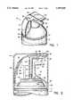
- FIG. 1is a perspective view of a dispensing actuator cap of the first embodiment of the present invention positioned on a container;
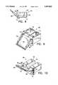
- FIG. 2is a cross-sectional view of the dispensing actuator cap of FIG. 1 positioned on the container, with an overcap;
- FIG. 3is a top view of the dispensing actuator cap of FIG. 1;
- FIG. 4is a rear view of the dispensing actuator cap of FIG. 1;
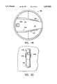
- FIG. 5is a bottom view of the dispensing actuator cap of FIG. 1;
- FIG. 6is a lower perspective view of the terminus portion of the lever portion of the dispensing actuator cap of FIG. 1, with the valve removed;
- FIG. 7is a rear perspective view of the valve
- FIG. 8is a side view of the valve of FIG. 7;
- FIG. 9is a bottom perspective view of the valve of FIG. 7;
- FIG. 10is a front perspective view of the valve of FIG. 7;
- FIG. 11is a cross-sectional view of the dispensing actuator cap of FIG. 1 in use
- FIG. 12is a perspective view of a dispensing actuator cap of the second embodiment of the present invention.
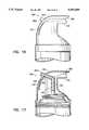
- FIG. 13is a cross-sectional view of the dispensing actuator cap of FIG. 12;
- FIG. 14is a perspective view of a dispensing actuator cap of the third embodiment of the present invention.
- FIG. 15is a cross-sectional view of the dispensing actuator cap of FIG. 14;
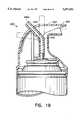
- FIG. 16is a side view of the fourth embodiment of the dispensing actuator cap of the present invention.
- FIG. 17is a cross-sectional view of the dispensing actuator cap of FIG. 16;
- FIG. 18is a top view of the dispensing actuator cap of FIG. 17;
- FIG. 19is a cross-sectional view of a modification of the fourth embodiment of the present invention.
- FIG. 20is a rear view of a portion of the dispensing actuator cap of FIG. 22;
- FIG. 21is a side view of another modification of the dispensing actuator cap of the fourth embodiment of the present invention.
- FIG. 22is a cross-sectional view of the embodiment of FIG. 21.
- FIG. 1is a perspective view of a first embodiment of a dispensing actuator 10 of the present invention in position on a container 12 (shown in part).
- the dispensing actuatorcan be a cap which snaps onto the container, as shown in FIGS. 1-2, or the dispensing actuator can be formed integral with the container.
- the container 12is a pressurized container with a valve stem 26 (shown in FIG. 2) and a valve (not shown) extending from a mounting cup 45, as is known in the art.
- the valveis preferably actuated by vertical displacement of the valve stem 26, but a tilt actuated valve can also be used.
- the dispensing actuator of the present inventioncan be used with other types of containers with other types of outlet means, as is discussed further below.
- FIG. 2is a partial, cross-sectional view of the cap 10 of FIG. 1 attached to the container 12.
- the cap 10comprises a generally circular closed base portion 14 which generally encircles the outer container bead 16 of the container 12.
- a rear, generally semi-circular wall portion 18 and a forward wall portion 20extend from the base portion 14.
- the walls 18 and 20are preferably recessed from the circumference of the base portion 14 to provide space to accommodate an overcap 34, shown in cross-section in FIG. 2.
- a shoulder 36is provided at the top of the base portion 14 for engaging and securing the overcap 34, which snaps onto the shoulder portion 36, as is known in the art.
- the overcap 34rests on a circumferential ledge portion 38 of the base 14.
- a first armis part of a lever portion 24, which extends from the rear wall 18, over the top and towards the front of the cap 10.
- the lever portion 24is preferably defined by a slot 28 in the rear wall 18, which preferably has a parallel portion 28a and a connecting portion 28b, best shown in the top and bottom views of FIGS. 3 and 5, respectively.
- a supporting rib 27is preferably provided in the interior of the cap 10 to partially define the slot 28. The rib 27 provides support to the lever arm 24. See also FIG. 5.
- the parallel slot portion 28adefines a hinge region, generally designated as 29, about which the lever portion 24 rotates.
- the lever portion 24can be rotated downward, preferably by a user's thumb, to actuate the container valve through displacement of the valve stem 26, shown in FIG. 2. Dispensing of material is discussed further, below.
- the hinge region 29is preferably in about the same horizontal plane as the top of the valve stem 26, as shown in FIG. 2. This minimizes the distance the lever arm 24 must be depressed to actuate the valve
- FIG. 3is a top view of the dispensing actuator cap 10 of FIG. 1, showing the parallel portion 28a and the connecting portion 28b in phantom. The remainder of the connecting portion 28b is obstructed in the view of FIG. 3 by the lever portion 24.
- FIG. 4is a rear view of the cap 10, showing the parallel portion 28a, the hinge portion 29 and the rear of the lever arm 24.
- a second, supporting arm 30extends from an upper portion 32 of the forward wall 20, beneath and in the same direction as the lever arm 24, as shown in FIGS. 1-2.
- the supporting arm 30provides a support for a user's finger, preferably the index finger, during actuation, and properly positions one's hand to receive dispensed product, as shown in FIG. 13 and described further, below.
- the supporting armis preferably essentially stationary. It is also preferably wider than the lever arm 24, as shown in FIG. 3.
- a product conveying duct 40has an essentially vertical tube portion 42 and an essentially horizontal tube portion 43.
- the horizontal tube portion 43is integral with the lever portion 24 while the vertical tube portion 42 depends from the lever portion 24.
- the bottom portion 44 of the vertical tube portion 42is adapted to engage the valve stem 26 of the container 12, as shown in FIG. 2.
- the discharge duct portion 40a of the product conveying duct 40coincides with the terminus portion 46 of the lever portion 24.
- the discharge duct portion 40ais preferably adapted to receive a product shutoff valve, such as the self-closing valve 48.
- the valve 48seals the discharge duct portion 40a when material is not being dispensed, preventing material left in the duct 40 from drying between uses.
- the valve 48also aids in keeping the product conveying duct 40 and discharge duct portion 40a free of contamination.
- the valveopens under the pressure of discharging product during actuation, as described, below.
- FIGS. 7-10illustrate various views of the valve 48. The valve is discussed in U.S. Ser. No. 08/011,342, filed on Jan. 26, 1993, and assigned to the assignee of the present invention.
- the valve 48has a base portion 50 with a shape matching the contour of the discharge duct portion 40a, shown, for example, in the partial perspective view of FIG. 6.
- the discharge duct portion 40a and the base portion 50are rectangular.
- the rear wall 58 of the base portion 50includes a rectangular recessed section 59 for receiving a rectangular protruding portion 52 of the discharge duct portion 40a. The engagement between the rectangular protruding portion 52 and the rectangular recessed section 59 secures and properly positions the valve 48.
- the horizontal dimension "L1" and the vertical dimension "L2" of the base portion 42, as shown in FIG. 7,are preferably slightly larger than the corresponding dimensions of the discharge duct portion 40a such that the base portion 50 will be held in position through a friction fit.
- the base portion 50completely seals the discharge duct portion 40a except for a passage 54, which is aligned with the product conveying duct 40 and allows for product passage on actuation, as described further, below.
- the insertcan also be secured within the discharge duct portion 40a through matching protrusions and indents on the mating side walls of the two parts, or other attaching means, such as glue.
- Vertical ribscan also be provided along the side walls of the base 50 to improve the seal between the side walls and the corresponding walls of the discharge duct portion 40a.
- the base portion 50also has a forward second wall 60 and preferably includes an extension 62 depending downwardly from the bottom of the base portion 50, proximate the second wall 60. This extension 62 acts as a stop which prevents insertion of the valve 48 too far into the discharge duct portion 40a.
- the passage 54is preferably provided in the top surface of the base portion 50 and extends through the base portion 50 from the first wall 58 to the second wall 60, to allow for the passage of dispensed product.
- the base portion 50preferably has hollowed sections 51, lessening the bulk material of the base and avoiding shrinkage during molding, as is known in the art.
- a resilient leaf spring portion 64 of the valve 48extends upward at an angle from a portion of the second wall 60 below the passage 54. It preferably extends from the bottom of the second wall 60 of the base 50. Walls 63 are preferably provided to reinforce the connection between the leaf spring 64 and the base portion 50. When positioned within the discharge duct portion 40a, the front edge 66 of the leaf spring 64 bears against the inside surface of the top of the discharge duct portion 40a with sufficient force to seal this surface, closing the product discharge duct 40, as shown in FIG. 2.
- the leaf spring portion 64preferably includes a pair of surfaces 68 and 70 which depend downwardly from the side edges of the leaf spring 64, perpendicular to the top surface of the leaf spring 64. See FIGS. 9-10.
- These surfaces 68 and 70are preferably tapered towards the front edge 66 and provide a seal with the side walls of the discharge duct portion 40a. This further improves the air tightness of the product conveying duct 40, preventing material left within the duct between uses from drying. These surfaces also prevent product from dispensing over the sides of the leaf spring portion 64, ensuring that the product is dispensed in a controlled, neat manner.
- the surfaces 68 and 70may be connected to the wall 60 through wall portions 72 and 74, respectively.
- the leaf spring 52itself is generally not deflected enough for its sides 68 and 70 to clear the side walls of the discharge duct portion 40a, also preventing dispensing of product from the sides.
- the length of the leaf spring portion 64 and its angle with respect to the base 50can be varied such that the top of the front edge 66 extends above the top of the base 50, as shown in FIG. 7. This is preferred because when the valve 48 is inserted into the discharge duct portion 40a, the leaf spring portion 64 will be forced backward by the top surface of the duct 40a. This provides initial stress on the leaf spring portion 64 which increases the force with which the leaf spring portion 64 bears against the top inside surface of the duct 40a, improving the seal along this surface. It also increases the restoring force of the leaf spring 64 during product dispensing, improving the closure of the valve when the container is no longer actuated. An angle of between about 40°-50° from horizontal is preferred for dispensing shaving cream, for example. An increased angle will increase the restoring force of the spring while a decreased angle will lessen it.
- Extending the leaf spring portion 64 sufficiently above the top of the base 50also increases the surface area of the leaf spring portion 64 bearing against the top inside surface of the discharge duct portion 40a. This also assists in cleanly cutting off the product stream when the actuator is released and improves the seal closing the discharge duct portion 40a.
- the leaf spring portion 40aWhen used in a dispensing actuator for shaving cream, it is preferred that the leaf spring portion 40a extend about 0.20-0.25 inches above the top of the base 50 at an angle of about 45°. This enables about three-quarters of the length of the leaf spring portion to bear against the top inside surface of the discharge duct portion 40a as shown in FIG. 2.
- the walls 63, and wall portions 72 and 74,are also provided to reinforce the leaf spring 64, increasing its restoring force.
- the restoring force of the valvecan also be varied by varying the thickness of the leaf spring portion 64 or the use of reinforcement, such as ribbing (not shown), extending from the edge 66 of the leaf spring 64 toward the second wall 60 of the base 50. While use of the valve 48 is preferred, other types of valves can be used, or no valve need be used.
- the leaf spring portion 64can be made wider than the base 50 and grooves can be provided in the side wall to receive the extended portion of the leaf spring.
- a semi-circular wall 82depends from the front wall 20 for engaging the mounting cup 45 of the container 12, securing the dispensing actuator cap 10 to the container 12.
- the wall 82preferably includes an annular protrusion 84 which snaps over the edge of the mounting cup 45. It is preferable that the cap 10 engage the mounting cup 45 rather than the container bead 16 because the diameter of mounting cups for pressurized containers have closer manufacturing tolerances than the diameter of pressurized containers themselves. The cap 10 can therefore be used on pressurized containers with a broad range of tolerances. Such a cap 10 may also be used with necked-in-containers which do not have an outer container bead to engage.
- the cap 10may be designed to engage a protruding container bead by adding a protrusion or an annular recess (not shown) to the bottom inner surface of the base portion 14 which may snap onto an outer container bead, similar to the protrusion 84 at the end of the semi-circular wall 82.
- FIG. 5shows the slot portions 28a, 28b, the product conveying duct 40, the semicircular wall 82 and the intersection 22 between the forward wall 20 and the rear wall 18.
- the container 12is resting on a surface, such as a sink or countertop.
- a surfacesuch as a sink or countertop.
- Arrow “A”indicates the direction of movement of one's thumb and the lever portion 24. This causes sufficient rotation of the lever portion 24 about hinge 29, toward the supporting arm 30, to actuate the valve stem 26. The closer one's thumb is to the end of the lever portion 24, the greater the mechanical advantage and the easier it would be to actuate the valve stem 26.
- Dispensing materialis forced up the product conveying duct 40, through passage 54 in the base 50 of the valve 48.
- the dispensing materialthen forces the resilient leaf spring portion 64 of the valve 48 aside, and exits the discharge duct portion 40a in the terminus portion 46 of the lever portion 24.
- the userreleases the pressure pinching the lever portion 24 and supporting arm 30, enabling the lever portion 24 to return to its natural position, closing the valve of the container 12.
- the valve of the containeris normally closed through spring action, as is known in the art.
- the leaf spring portion 64 of the valve 48then returns to its natural position bearing against the upper inside surface of the discharge duct portion 40a, cutting off the product stream and sealing the product conveying duct 40.
- one's handBy properly positioning one's thumb and index finger, one's hand assumes an optimum position for receiving material from the discharge duct portion 40a, as shown in FIG. 11. This semi-closed position of the hand enables easier actuation than traditional actuation requiring an extended index finger. Since one's thumb is shorter than one's index finger, and is such a strong digit, it can generate greater leverage against the forces of the cap and valve of the container resisting actuation.
- the lever portion 24preferably extends slightly beyond the supporting arm 30, as shown in FIG. 1. It is also preferable that the lever arm 24 extend beyond the supporting arm 30, to accommodate the natural position of the thumb. One's index finger, which bears against the supporting arm 30, naturally extends further from one's hand than the thumb, which engages the forward part 24a of the lever portion 24. Both arms are within the plane of the circumference of the base portion 14 of dispensing actuator cap 10, enabling the use of a protective overcap 34, shown in cross-section in FIG. 2. Maintaining the lever portion 24 and supporting arm within the plane of the circumference of the base portion 14 also makes the container/cap combination easier to assemble on an assembly line, package for shipment, and stack on a shelf.
- This embodiment of the inventioncan be used to dispense shaving cream, soap, cosmetics, tanning lotion, medical products and many other products directly into the same hand which actuates the cap, freeing the user's second hand.
- the inventioncan also be used to dispense material onto a toothbrush, spoon, or other such device held in the same hand that actuates the cap. While preferred, the supporting arm need not be provided. In such case, a user's thumb would rotate the lever arm 24 to dispense material into the same hand as the thumb, into one's free hand, or onto an object.
- FIGS. 12-13A second embodiment of the dispensing actuator of the present invention is shown in FIGS. 12-13.
- the lever portion 124 and the supporting arm 130extend beyond the plane of the circumference of the cap 100 and container 12.
- the cap 100comprises a generally circular closed outer wall 118 which generally encircles the outer container bead 16 of the container 12. Since the lever portion 124 and supporting arm 130 extend beyond the plane of the circumference of the container 12, there is no need for a recessed front wall portion as in the first embodiment.
- a semi-circular wall 182 with an annular protrusion 184preferably depends from the inside surface of the generally circular closed outer wall 118, for engaging the mounting cup 45 of the container 12, as discussed in reference to the first embodiment of the invention.
- the outer wall 118can be adapted to engage the container bead 16.
- the lever portion 124is preferably defined by a slot 128, with a parallel portion 128a and a connecting portion 128b in the outer wall 180.
- a supporting rib 127is provided to reinforce the lever portion 124.
- the hinge region 129extends below the level of the valve stem 26. This increases the displacement of the valve stem 26 on rotation of the lever portion 124 in this embodiment.
- the distance between the terminus portion 146 of the lever portion 124 and the hinge 129is almost three times the distance from the valve stem 126 to the hinge 129, providing even greater leverage and mechanical advantage than the first embodiment.
- a recess 125is optionally provided in the top of the lever portion 140, for more comfortable placement of the thumb on actuation. Such a recess could be provided in any of the embodiments shown herein.
- this embodimentWhen used to dispense viscous or semi-solid materials such as shaving cream, soap or toothpaste, this embodiment also preferably provides a product shutoff valve, such as the self-closing valve 48, in the discharge duct portion 140a, as discussed with reference to the first embodiment.
- a product shutoff valvesuch as the self-closing valve 48
- the second embodimentis operated in the same way as the first. While the discharge duct portion 140a is shown in the terminus portion 146 of the lever portion 124, it could be recessed from it, dispensing product closer to the cap or in a direction below the lever portion 124. While preferred, the supporting arm 130 need not be provided, as described with respect to the first embodiment.
- FIGS. 14-15show an additional embodiment of the present invention which is similar to that of FIGS. 1-5, except that the horizontal tube portion 243 of the product conveying duct 240 is integral with the supporting arm 230.
- the discharge duct portion 240ais preferably in the terminus portion 230a of the supporting arm 230.
- the discharge duct portion 240acould also be recessed from the terminus portion 230a, for dispensing of product closer to the cap or in a direction below the supporting arm.
- the lever arm 224defined by the slot 228, includes a downwardly depending portion 224a which is preferably aligned with the vertical axis of the valve stem 26 and the vertical tube portion 242. See FIG. 15. The portion 224a is positioned with a small clearance with the top of the vertical tube portion 242, which engages the valve stem 26.
- Other illustrated portions of the cap 200are the same as those described with respect to earlier embodiments.
- valve of the containeris preferably actuated by vertical displacement.
- the discharge duct portion 240preferably includes the self-closing valve, valve 48, which has been described in relation to FIGS. 6-10.
- the second embodimentcould be modified in a similar fashion to dispense from the supporting arm, as well.
- the "pinching" actuation technique and lever arm configurationprovide mechanical advantages easing operation, they may be advantageously employed in more traditional dispensing configurations, such as where the product is dispensed in a direction away from the person actuating the container.
- the dual arm configurationcan be used to hold and aim the dispensing actuator and container during use, as well as to actuate the container. This configuration would be useful for air fresheners and household treatments such as window cleaners, disinfectants, insecticides, and the like, in addition to shaving cream, toothpaste, soap or other such materials.
- the pinch actuation techniquecould be advantageously applied by arranging the arms side by side, as well.
- FIGS. 16-18are side, cross-section, and top views, respectively, of such a cap 300, wherein the discharge duct portion 340a of the product discharge passage 340 is not associated with either the terminus portion 346 of the lever portion 324 or with the supporting arm 330.
- the vertical tube portion 342merges with a tube portion 343 which extends through a portion of the cap, such as through the portion of the rear wall 318 within the slot portion 328 defining the lever arm 324. While shown angled, this tube portion 343 can also extend essentially horizontally or essentially vertically.
- the discharge duct portion 340apreferably extends just slightly beyond the rear wall 318, to allow for an overcap (not shown). The discharge duct portion 340a could extend out farther if an overcap is not needed.
- This cap 300is operated in the same way as the cap 10 of FIGS. 1-5, except that the cap and container must be pointed in the desired direction or location for dispensing material. Displacement of the lever portion 324 causes a displacement of the angled tube portion 343 and vertical tube portion 342, causing actuation of the valve of the container 12.
- the discharge duct portion 340acan be positioned for discharge anywhere along the lever portion 324.
- a dispensing actuator made in accordance with this embodiment of the inventioncould be advantageously used to dispense material into one's free hand, onto an object such as a toothbrush, onto a surface or into the air, for example.
- FIGS. 12-13could similarly be adapted for rear dispensing.
- a further modification to the fourth embodimentenables variable positioning of the discharge duct portion 440a by a consumer, as shown in FIG. 19.
- the vertical tube portion 442merges with the tube portion 443 through a flexible region 444.
- the rear part of the lever portion 424includes a series of detents 445 through which the angled tube portion 443 can be advanced to adjust the position of the discharge duct portion 440a.
- FIG. 20is a partial rear view of the dispensing cap 400, showing the location of the detents 445. Three pairs of detents 445 are located such that the discharge duct portion 440a can be located about 10° below the horizontal, 45° from horizontal and in a vertical position. Additional positions can be provided, as well.
- the detents 445should securely engage the angled tube portion 443 to ensure a precise discharge position, and enable rotation of the lever portion 424 on actuation to sufficiently displace the tube portion 443 and vertical tube portion 442 to actuate the container valve.
- the flexible tube portioncan be molded from polypropylene.
- FIGS. 21-22illustrate another modification to the fourth embodiment, wherein the supporting arm 530 is curved downward to provide a region that the index finger can wrap around, enabling a more secure grip on the cap 500 during dispensing, as well as improving the user's ability to aim the cap.
- the supporting arm 530forms an upper part of a ring, generally designated as 535.
- the ring 535is preferred because it can also serve as a convenient means for carrying the container 512 with one's finger slipped through the ring 535.
- the rear of the ring 535preferably includes an additional arm 536 which provides support for the user's middle finger. This further secures the user's grip and aim while dispensing.
- Such an additional armcan also be provided extending from the cap itself, in this or any of the embodiments shown.
- the product conveying duct 540can comprise a vertical tube portion 542 and a horizontal tube portion 543.
- a ridge 525can be provided on the lever portion 524 for a user's thumb to bear against, if desired.
- the capis attached to the container 12 through an annular protrusion 584 which snaps over the edge of the container bead 16. This embodiment can be adopted to engage the mounting cup 45, as well.
- one's thumbpreferably engages the terminus portion 546 of the lever portion 524, while one's index finger of the same hand slips through the ring portion 535, and is supported by the supporting arm 530.
- One's middle fingercan be supported by the additional arm 536.
- Pressure exerted by one's thumb on the lever portion 524rotates the lever portion 546 toward the supporting arm 530, displacing the vertical tube portion 542 downward, actuating the valve of the container 518.
- the valveis preferably actuated through vertical displacement, but this embodiment can be configured for tilt actuation as well.
- FIGS. 21-22Easy to actuate and direct while held in the hand, the embodiment of FIGS. 21-22 is useful for dispensing all types of materials, including air fresheners, window cleaners and other household cleaning goods, or insecticides. It can be particularly useful where prolonged steady usage is required, such as in applying spray paint, because it is so easy to hold. This embodiment could also be particularly useful in actuating pump dispensers.
- the dispensing actuator cap of all the embodiments shown and the self-closing valve 48are preferably made of a commercially available plastic, such as an olefin.
- the plasticshould be resilient, suitable for molding and chemically resistant to the material to be dispensed from the container.
- Polypropylene and polyethyleneare preferred because they are inexpensive, enable high cycle times during molding, and are chemically resistant to commonly dispensed products.
- the plasticcan be filled, such as with talc or glass, for added strength and resilience.
- Engineering resins, such as certain polyamides, polyacetyls, polycarbonates, acrylonitrilebutadienestyrene and nylon meeting the criteria of resilience, ease of molding and chemical resistancecan also be used, particularly for the valve 48.
- a preferred polypropylene for the dispensing actuator cap and valve memberis Pro-fax (TM) PD-701N, a high flow nucleated homopolymer resin from HIMONT Incorporated.
- valve 48The material chosen for the valve 48 must have sufficient resilience for the leaf spring portion 64 of the valve member to maintain its normally closed position sealing the product passage 40 and to return to its normally closed position when material is not being dispensed.
- the cap and valve memberneed not be of the same material.
- the dispensing actuator cap of the present inventionis preferably molded in one piece by injection molding or other conventional molding processes, as is known in the art.
- the valve memberis preferably molded separately. Separate molding enables the valve member to be formed such that the leaf spring portion extends above the top of the base, as described above, enabling its insertion under stress, increasing the force and surface area with which it bears against the inside surface of the discharge duct portion.
- the dispensing actuator of the present inventionhas been described in use with a pressurized container. Any of the known barrier package systems, such as those using a piston or those referred to as a bag-in-can, may also be used. See, for example, San Rafael, Michael L., "Alternative Systems Push for Market Share,” Spray Technology & Marketing, August 1992, pp. 37-44, for a discussion of such systems.
- the dispenser of the present inventioncan also be used with manually pressurized containers, including pump type dispensing systems. It can be used with wall dispensers or other types of dispensing systems, as well.
- the dispensing actuator of the present inventionis a unique and preferred embodiment of this invention which allows for the dispensing of a wide variety of materials towards the user. This in turn allows product to be dispensed directly and conveniently into one's hand or articles held in one's hand, such as toothbrushes, spoons, brushes or the like, in single handed operation.
- the dispensing actuator of the present inventionis also useful for dispensing a wide variety of materials through a discharge duct located in some other portion of the cap for dispensing of material in a direction away from the user. In both cases the mechanical leverage provided by the configuration of the cap increases the force transmitted to the valve of the container. This, coupled with the natural strength of the thumb, enables easier and more controlled dispensing of material than is possible with dispensers actuated by finger pressure directly above the valve of the container.
Landscapes
- Chemical & Material Sciences (AREA)
- Dispersion Chemistry (AREA)
- Engineering & Computer Science (AREA)
- Mechanical Engineering (AREA)
- Closures For Containers (AREA)
- Containers And Packaging Bodies Having A Special Means To Remove Contents (AREA)
Abstract
Description
______________________________________Properties Pro-fax PD-701N ASTM Method______________________________________Melt Flow dg/min. 35 D1238Density, g/cm.sup.3 0.9 D792Flexural Modulus, psi (MPa) 220,000 (1500) D790Tensile Strength 5,100 (35) D638at yield, psi (MPa)Elongation @ Yield, % 10 D638Deflection Temperature, 250 (121) D648°F. (°C.) @ psi (455 kPa)______________________________________
Claims (8)
Priority Applications (1)
| Application Number | Priority Date | Filing Date | Title |
|---|---|---|---|
| US08/071,769US5597095A (en) | 1993-06-09 | 1993-06-09 | Dual arm aerosol actuator having a movable and stationary arm |
Applications Claiming Priority (1)
| Application Number | Priority Date | Filing Date | Title |
|---|---|---|---|
| US08/071,769US5597095A (en) | 1993-06-09 | 1993-06-09 | Dual arm aerosol actuator having a movable and stationary arm |
Related Child Applications (1)
| Application Number | Title | Priority Date | Filing Date |
|---|---|---|---|
| US29017100Continuation-In-Part | 1994-01-05 |
Publications (1)
| Publication Number | Publication Date |
|---|---|
| US5597095Atrue US5597095A (en) | 1997-01-28 |
Family
ID=22103465
Family Applications (1)
| Application Number | Title | Priority Date | Filing Date |
|---|---|---|---|
| US08/071,769Expired - LifetimeUS5597095A (en) | 1993-06-09 | 1993-06-09 | Dual arm aerosol actuator having a movable and stationary arm |
Country Status (1)
| Country | Link |
|---|---|
| US (1) | US5597095A (en) |
Cited By (43)
| Publication number | Priority date | Publication date | Assignee | Title |
|---|---|---|---|---|
| GB2324576A (en)* | 1997-01-07 | 1998-10-28 | Univ Aberdeen | Holder and actuator for dispensing fluid from a container |
| US5839616A (en) | 1997-08-14 | 1998-11-24 | The Procter & Gamble Company | Blow molded container having pivotal connector for an actuation lever |
| FR2796623A1 (en)* | 1999-07-22 | 2001-01-26 | Oreal | DISPENSING HEAD WITH IMPROVED OPERATING NOISE AND PACKAGING AND DISPENSING DEVICE THUS EQUIPPED |
| FR2796624A1 (en)* | 1999-07-22 | 2001-01-26 | Oreal | DISPENSING HEAD WITH IMPROVED OPERATING NOISE AND PACKAGING AND DISPENSING DEVICE THUS EQUIPPED |
| US6260738B1 (en)* | 1999-06-15 | 2001-07-17 | The Procter & Gamble Company | Nozzle having upward moving straw while communicating upright dispensing |
| US20040222246A1 (en)* | 2003-05-05 | 2004-11-11 | The Procter & Gamble Company | Sprayer actuator, sprayer, and method of making the same |
| US20050062202A1 (en)* | 2001-12-08 | 2005-03-24 | Incro Limited | Method of manufacturing a nozzle arrangement |
| USD509136S1 (en) | 2003-08-04 | 2005-09-06 | Peter J. Walters | Actuator |
| US20070034653A1 (en)* | 2005-08-12 | 2007-02-15 | Strand Toralf H | Spray actuating mechanism for a dispensing canister |
| US20070051754A1 (en)* | 2005-09-08 | 2007-03-08 | Strand Toralf H | Button actuated mechanism for a dispensing canister |
| US20070131804A1 (en)* | 2005-12-08 | 2007-06-14 | L'oreal | Diffuser and device for packaging and dispensing a foaming product |
| US7341056B1 (en)* | 2005-05-25 | 2008-03-11 | The Big Ox, L.L.C. | Portable oxygen supply unit |
| USD590712S1 (en) | 2008-06-02 | 2009-04-21 | Meadwestvaco Calmar, Inc. | Sprayer |
| USD600119S1 (en) | 2007-05-04 | 2009-09-15 | Meadwestvaco Calmar, Inc. | Sprayer shroud |
| US20090283609A1 (en)* | 2006-06-21 | 2009-11-19 | Summit Packaging Systems, Inc. | One-piece trigger cap for a spray dispenser |
| US20090321381A1 (en)* | 2008-06-30 | 2009-12-31 | Paas Edward L | Overcap for and a method of actuating a volatile material dispenser |
| USD627224S1 (en) | 2009-10-08 | 2010-11-16 | S.C. Johnson & Son, Inc. | Overcap |
| US20110132936A1 (en)* | 2009-12-04 | 2011-06-09 | Jin-Sheng Weng | Lid spray head for a high pressure gas container |
| WO2012006532A1 (en)* | 2010-07-08 | 2012-01-12 | The Procter & Gamble Company | Device for dispensing material |
| US20120031933A1 (en)* | 2010-05-21 | 2012-02-09 | Andersen Daniel A | Shroud and Dispensing System for a Handheld Container |
| US8251255B1 (en) | 2004-07-02 | 2012-08-28 | Homax Products, Inc. | Aerosol spray texture apparatus for a particulate containing material |
| US8272542B2 (en) | 2008-02-29 | 2012-09-25 | Safeworld International Inc. | Spray can handle attachment |
| US8313011B2 (en) | 1992-02-24 | 2012-11-20 | Homax Products, Inc. | Systems and methods for applying texture material to ceiling surfaces |
| US8317065B2 (en) | 1992-02-24 | 2012-11-27 | Homax Products, Inc. | Actuator systems and methods for aerosol wall texturing |
| US8336742B2 (en) | 2004-10-08 | 2012-12-25 | Homax Products, Inc. | Aerosol systems and methods for dispensing texture material |
| US8342421B2 (en) | 2004-01-28 | 2013-01-01 | Homax Products Inc | Texture material for covering a repaired portion of a textured surface |
| US8353465B2 (en) | 2003-04-10 | 2013-01-15 | Homax Products, Inc | Dispensers for aerosol systems |
| US8551572B1 (en) | 2007-04-04 | 2013-10-08 | Homax Products, Inc. | Spray texture material compositions, systems, and methods with anti-corrosion characteristics |
| US8580349B1 (en) | 2007-04-05 | 2013-11-12 | Homax Products, Inc. | Pigmented spray texture material compositions, systems, and methods |
| US8701944B2 (en) | 1992-02-24 | 2014-04-22 | Homax Products, Inc. | Actuator systems and methods for aerosol wall texturing |
| US8844765B2 (en) | 1993-03-12 | 2014-09-30 | Homax Products, Inc. | Aerosol spray texture apparatus for a particulate containing material |
| USD718624S1 (en) | 2013-06-14 | 2014-12-02 | Homax Products, Inc. | Actuator assembly |
| WO2014071180A3 (en)* | 2012-11-01 | 2015-07-23 | Precision Valve Corporation | Free flow aerosol valve |
| US9156042B2 (en) | 2011-07-29 | 2015-10-13 | Homax Products, Inc. | Systems and methods for dispensing texture material using dual flow adjustment |
| US9156602B1 (en) | 2012-05-17 | 2015-10-13 | Homax Products, Inc. | Actuators for dispensers for texture material |
| US9211994B2 (en) | 2010-05-21 | 2015-12-15 | S.C. Johnson & Son, Inc. | Shroud and dispensing system for a handheld container |
| US9248457B2 (en) | 2011-07-29 | 2016-02-02 | Homax Products, Inc. | Systems and methods for dispensing texture material using dual flow adjustment |
| US9382060B1 (en) | 2007-04-05 | 2016-07-05 | Homax Products, Inc. | Spray texture material compositions, systems, and methods with accelerated dry times |
| US9435120B2 (en) | 2013-03-13 | 2016-09-06 | Homax Products, Inc. | Acoustic ceiling popcorn texture materials, systems, and methods |
| US20170008692A1 (en)* | 2014-02-14 | 2017-01-12 | Summit Packaging Systems, Inc. | Dispensing valve incorporating a metering valve |
| USD787326S1 (en) | 2014-12-09 | 2017-05-23 | Ppg Architectural Finishes, Inc. | Cap with actuator |
| US9776785B2 (en) | 2013-08-19 | 2017-10-03 | Ppg Architectural Finishes, Inc. | Ceiling texture materials, systems, and methods |
| US20180099808A1 (en)* | 2015-04-06 | 2018-04-12 | S. C. Johnson & Son, Inc. | Dispensing systems |
Citations (44)
| Publication number | Priority date | Publication date | Assignee | Title |
|---|---|---|---|---|
| US729423A (en)* | 1900-11-03 | 1903-05-26 | Eugen Scheiber | Compression stop-cock. |
| US1969960A (en)* | 1932-11-30 | 1934-08-14 | Hosmer L Bium | Drink dispenser |
| US2303130A (en)* | 1940-09-14 | 1942-11-24 | Moon Shung | Fluid discharge device |
| US2378451A (en)* | 1943-11-17 | 1945-06-19 | Wilbur E Vensel | Dispensing bottle cap |
| US2400231A (en)* | 1945-06-29 | 1946-05-14 | Gebauer Chemical Company | Means for dispensing liquids having low boiling points |
| US2605021A (en)* | 1948-07-16 | 1952-07-29 | Churchill Henry Winsto Spencer | Dispenser for an inverted container with means for locking said container thereto and a self-closing outlet element |
| US2632585A (en)* | 1946-10-16 | 1953-03-24 | Knapp Monarch Co | Liquid spraying valve structure |
| US2702957A (en)* | 1952-09-26 | 1955-03-01 | Zonite Products Corp | Valved closure |
| US2820578A (en)* | 1955-05-25 | 1958-01-21 | Dickman Max | Holders for pressure-actuated canisters |
| US2822054A (en)* | 1955-05-09 | 1958-02-04 | Gen Pacific Corp | Fire extinguisher |
| US2822961A (en)* | 1954-06-25 | 1958-02-11 | Nels W Seaquist | Aerosol bomb |
| US2877934A (en)* | 1956-11-19 | 1959-03-17 | H H Helbush | Detachable handle for gas-loaded dispensing containers |
| US2908334A (en)* | 1957-03-14 | 1959-10-13 | Union Carbide Corp | Process and apparatus for generating and discharging foam |
| US3085720A (en)* | 1959-08-05 | 1963-04-16 | Rhone Poulenc Sa | Atomising discharge valves |
| US3100065A (en)* | 1960-08-03 | 1963-08-06 | Hilbert W Gross | Holder for pressurized toothpaste dispensers |
| US3104061A (en)* | 1959-08-05 | 1963-09-17 | Rhone Poulenc Sa | Atomising discharge valves |
| US3138331A (en)* | 1962-07-30 | 1964-06-23 | Louis F Kutik | Actuator for pressurized dispensing cans |
| US3159319A (en)* | 1962-07-30 | 1964-12-01 | Parish Roy | Actuator-adapter for spray can |
| US3161331A (en)* | 1962-11-15 | 1964-12-15 | Risdon Mfg Co | Closure for pressurized packages |
| US3162332A (en)* | 1961-10-19 | 1964-12-22 | Hayim Joseph Hayim | Apparatus for disseminating pulverulent material |
| US3211384A (en)* | 1963-09-03 | 1965-10-12 | Seaquist Valve Co | Dispensing head |
| US3323686A (en)* | 1965-06-04 | 1967-06-06 | Geigy Ag J R | Apparatus for atomizing liquids |
| US3539151A (en)* | 1968-03-05 | 1970-11-10 | Reid Valve Co Inc | Valve constuction |
| US3584789A (en)* | 1969-02-25 | 1971-06-15 | John S Traynor | Self-purging nozzle and valve apparatus |
| US3588040A (en)* | 1968-07-17 | 1971-06-28 | Modern Faucet Mfg Co | Spray valve |
| US3595445A (en)* | 1969-01-27 | 1971-07-27 | Rayford Ind Inc | Fluid-dispensing valve |
| US3625403A (en)* | 1968-04-05 | 1971-12-07 | Ciba Geigy Corp | Aerosol-type dispenser for dispensing a powdered material |
| US3704811A (en)* | 1970-07-24 | 1972-12-05 | Creative Ideas Inc | Portable sandblaster |
| US3788526A (en)* | 1973-02-12 | 1974-01-29 | Ciba Geigy Corp | Compressed air operated dispenser with mechanical force multiplying means |
| US4061250A (en)* | 1975-05-31 | 1977-12-06 | Tetsuya Tada | Depress button type sprayer |
| US4186855A (en)* | 1978-06-19 | 1980-02-05 | Zotos International, Inc. | Spray pump actuating and bottle holding device |
| US4345702A (en)* | 1980-08-25 | 1982-08-24 | The United States Of America As Represented By The Secretary Of The Army | Fiber disseminator |
| US4530448A (en)* | 1983-05-11 | 1985-07-23 | Ponyicky John F | Wall mounted liquid dispenser |
| US4671436A (en)* | 1984-07-31 | 1987-06-09 | Mckesson Corporation | Syphon assembly and package incorporating the assembly |
| US4684037A (en)* | 1984-01-06 | 1987-08-04 | Giuliano Gnutti | Perfected mechanical control device for ball valve type valve systems |
| US4742963A (en)* | 1986-02-21 | 1988-05-10 | Marvaldi Douglas A | Aerosol airbrush |
| US4756347A (en)* | 1985-11-19 | 1988-07-12 | Jopado Baderi | Filling and dispensing valve, adapter and package |
| US4773571A (en)* | 1986-03-27 | 1988-09-27 | Mckesson Corporation | Seltzer package, valve, poppet and spring |
| US4782982A (en)* | 1987-01-15 | 1988-11-08 | Root-Lowell Manufacturing Company | Self-pressurizing sprayer |
| US4850387A (en)* | 1987-12-15 | 1989-07-25 | Nicholas Bassill | Liquid dispensing valve |
| US5014963A (en)* | 1988-11-08 | 1991-05-14 | Sanden Corporation | Valve apparatus for preventing leakage of a beverage |
| US5018647A (en)* | 1982-06-08 | 1991-05-28 | Abplanalf Robert H | Dispensing cap for use with pressurized container |
| US5118080A (en)* | 1989-07-15 | 1992-06-02 | Suttner Gmbh & Co. Kg | Valve pistol for a high pressure cleaning apparatus |
| US5154328A (en)* | 1989-07-25 | 1992-10-13 | L'oreal | Unit for dispensing at least one fluid product, in particular a cosmetic or pharmaceutical product, having a pressure actuated, self-sealing, closure outlet |
- 1993
- 1993-06-09USUS08/071,769patent/US5597095A/ennot_activeExpired - Lifetime
Patent Citations (45)
| Publication number | Priority date | Publication date | Assignee | Title |
|---|---|---|---|---|
| US729423A (en)* | 1900-11-03 | 1903-05-26 | Eugen Scheiber | Compression stop-cock. |
| US1969960A (en)* | 1932-11-30 | 1934-08-14 | Hosmer L Bium | Drink dispenser |
| US2303130A (en)* | 1940-09-14 | 1942-11-24 | Moon Shung | Fluid discharge device |
| US2378451A (en)* | 1943-11-17 | 1945-06-19 | Wilbur E Vensel | Dispensing bottle cap |
| US2400231A (en)* | 1945-06-29 | 1946-05-14 | Gebauer Chemical Company | Means for dispensing liquids having low boiling points |
| US2632585A (en)* | 1946-10-16 | 1953-03-24 | Knapp Monarch Co | Liquid spraying valve structure |
| US2605021A (en)* | 1948-07-16 | 1952-07-29 | Churchill Henry Winsto Spencer | Dispenser for an inverted container with means for locking said container thereto and a self-closing outlet element |
| US2702957A (en)* | 1952-09-26 | 1955-03-01 | Zonite Products Corp | Valved closure |
| US2822961A (en)* | 1954-06-25 | 1958-02-11 | Nels W Seaquist | Aerosol bomb |
| US2822054A (en)* | 1955-05-09 | 1958-02-04 | Gen Pacific Corp | Fire extinguisher |
| US2820578A (en)* | 1955-05-25 | 1958-01-21 | Dickman Max | Holders for pressure-actuated canisters |
| US2877934A (en)* | 1956-11-19 | 1959-03-17 | H H Helbush | Detachable handle for gas-loaded dispensing containers |
| US2908334A (en)* | 1957-03-14 | 1959-10-13 | Union Carbide Corp | Process and apparatus for generating and discharging foam |
| US3104061A (en)* | 1959-08-05 | 1963-09-17 | Rhone Poulenc Sa | Atomising discharge valves |
| US3085720A (en)* | 1959-08-05 | 1963-04-16 | Rhone Poulenc Sa | Atomising discharge valves |
| US3254807A (en)* | 1959-08-05 | 1966-06-07 | Companhia Quimica Rhodia Brasi | Atomising discharge valves |
| US3100065A (en)* | 1960-08-03 | 1963-08-06 | Hilbert W Gross | Holder for pressurized toothpaste dispensers |
| US3162332A (en)* | 1961-10-19 | 1964-12-22 | Hayim Joseph Hayim | Apparatus for disseminating pulverulent material |
| US3138331A (en)* | 1962-07-30 | 1964-06-23 | Louis F Kutik | Actuator for pressurized dispensing cans |
| US3159319A (en)* | 1962-07-30 | 1964-12-01 | Parish Roy | Actuator-adapter for spray can |
| US3161331A (en)* | 1962-11-15 | 1964-12-15 | Risdon Mfg Co | Closure for pressurized packages |
| US3211384A (en)* | 1963-09-03 | 1965-10-12 | Seaquist Valve Co | Dispensing head |
| US3323686A (en)* | 1965-06-04 | 1967-06-06 | Geigy Ag J R | Apparatus for atomizing liquids |
| US3539151A (en)* | 1968-03-05 | 1970-11-10 | Reid Valve Co Inc | Valve constuction |
| US3625403A (en)* | 1968-04-05 | 1971-12-07 | Ciba Geigy Corp | Aerosol-type dispenser for dispensing a powdered material |
| US3588040A (en)* | 1968-07-17 | 1971-06-28 | Modern Faucet Mfg Co | Spray valve |
| US3595445A (en)* | 1969-01-27 | 1971-07-27 | Rayford Ind Inc | Fluid-dispensing valve |
| US3584789A (en)* | 1969-02-25 | 1971-06-15 | John S Traynor | Self-purging nozzle and valve apparatus |
| US3704811A (en)* | 1970-07-24 | 1972-12-05 | Creative Ideas Inc | Portable sandblaster |
| US3788526A (en)* | 1973-02-12 | 1974-01-29 | Ciba Geigy Corp | Compressed air operated dispenser with mechanical force multiplying means |
| US4061250A (en)* | 1975-05-31 | 1977-12-06 | Tetsuya Tada | Depress button type sprayer |
| US4186855A (en)* | 1978-06-19 | 1980-02-05 | Zotos International, Inc. | Spray pump actuating and bottle holding device |
| US4345702A (en)* | 1980-08-25 | 1982-08-24 | The United States Of America As Represented By The Secretary Of The Army | Fiber disseminator |
| US5018647A (en)* | 1982-06-08 | 1991-05-28 | Abplanalf Robert H | Dispensing cap for use with pressurized container |
| US4530448A (en)* | 1983-05-11 | 1985-07-23 | Ponyicky John F | Wall mounted liquid dispenser |
| US4684037A (en)* | 1984-01-06 | 1987-08-04 | Giuliano Gnutti | Perfected mechanical control device for ball valve type valve systems |
| US4671436A (en)* | 1984-07-31 | 1987-06-09 | Mckesson Corporation | Syphon assembly and package incorporating the assembly |
| US4756347A (en)* | 1985-11-19 | 1988-07-12 | Jopado Baderi | Filling and dispensing valve, adapter and package |
| US4742963A (en)* | 1986-02-21 | 1988-05-10 | Marvaldi Douglas A | Aerosol airbrush |
| US4773571A (en)* | 1986-03-27 | 1988-09-27 | Mckesson Corporation | Seltzer package, valve, poppet and spring |
| US4782982A (en)* | 1987-01-15 | 1988-11-08 | Root-Lowell Manufacturing Company | Self-pressurizing sprayer |
| US4850387A (en)* | 1987-12-15 | 1989-07-25 | Nicholas Bassill | Liquid dispensing valve |
| US5014963A (en)* | 1988-11-08 | 1991-05-14 | Sanden Corporation | Valve apparatus for preventing leakage of a beverage |
| US5118080A (en)* | 1989-07-15 | 1992-06-02 | Suttner Gmbh & Co. Kg | Valve pistol for a high pressure cleaning apparatus |
| US5154328A (en)* | 1989-07-25 | 1992-10-13 | L'oreal | Unit for dispensing at least one fluid product, in particular a cosmetic or pharmaceutical product, having a pressure actuated, self-sealing, closure outlet |
Cited By (84)
| Publication number | Priority date | Publication date | Assignee | Title |
|---|---|---|---|---|
| US8573451B2 (en) | 1992-02-24 | 2013-11-05 | Homax Products, Inc. | Actuator systems and methods for aerosol wall texturing |
| US9181020B2 (en) | 1992-02-24 | 2015-11-10 | Homax Products, Inc. | Actuator systems and methods for aerosol wall texturing |
| US8584898B2 (en) | 1992-02-24 | 2013-11-19 | Homax Products, Inc. | Systems and methods for applying texture material to ceiling surfaces |
| US8313011B2 (en) | 1992-02-24 | 2012-11-20 | Homax Products, Inc. | Systems and methods for applying texture material to ceiling surfaces |
| US9079703B2 (en) | 1992-02-24 | 2015-07-14 | Homax Products, Inc. | Actuator systems and methods for aerosol wall texturing |
| US8985392B2 (en) | 1992-02-24 | 2015-03-24 | Homax Products, Inc. | Systems and methods for applying texture material to ceiling surfaces |
| US8701944B2 (en) | 1992-02-24 | 2014-04-22 | Homax Products, Inc. | Actuator systems and methods for aerosol wall texturing |
| US9845185B2 (en) | 1992-02-24 | 2017-12-19 | Ppg Architectural Finishes, Inc. | Systems and methods for applying texture material |
| US8317065B2 (en) | 1992-02-24 | 2012-11-27 | Homax Products, Inc. | Actuator systems and methods for aerosol wall texturing |
| US8505786B2 (en) | 1992-02-24 | 2013-08-13 | Homax Products, Inc. | Actuator systems and methods for aerosol wall texturing |
| US8887953B2 (en) | 1992-02-24 | 2014-11-18 | Homax Products, Inc. | Systems and methods for applying texture material to ceiling surfaces |
| US8844765B2 (en) | 1993-03-12 | 2014-09-30 | Homax Products, Inc. | Aerosol spray texture apparatus for a particulate containing material |
| GB2324576A (en)* | 1997-01-07 | 1998-10-28 | Univ Aberdeen | Holder and actuator for dispensing fluid from a container |
| US5839616A (en) | 1997-08-14 | 1998-11-24 | The Procter & Gamble Company | Blow molded container having pivotal connector for an actuation lever |
| US6260738B1 (en)* | 1999-06-15 | 2001-07-17 | The Procter & Gamble Company | Nozzle having upward moving straw while communicating upright dispensing |
| US6502726B1 (en) | 1999-07-22 | 2003-01-07 | L'oreal | Packaging and dispensing device fitted with a dispenser head |
| EP1072316A1 (en)* | 1999-07-22 | 2001-01-31 | L'oreal | Packaging and dispensing device with a dispensing head |
| FR2796624A1 (en)* | 1999-07-22 | 2001-01-26 | Oreal | DISPENSING HEAD WITH IMPROVED OPERATING NOISE AND PACKAGING AND DISPENSING DEVICE THUS EQUIPPED |
| FR2796623A1 (en)* | 1999-07-22 | 2001-01-26 | Oreal | DISPENSING HEAD WITH IMPROVED OPERATING NOISE AND PACKAGING AND DISPENSING DEVICE THUS EQUIPPED |
| US20050062202A1 (en)* | 2001-12-08 | 2005-03-24 | Incro Limited | Method of manufacturing a nozzle arrangement |
| US8353465B2 (en) | 2003-04-10 | 2013-01-15 | Homax Products, Inc | Dispensers for aerosol systems |
| US8820656B2 (en) | 2003-04-10 | 2014-09-02 | Homax Products, Inc. | Dispenser for aerosol systems |
| US9132953B2 (en) | 2003-04-10 | 2015-09-15 | Homax Products, Inc. | Dispenser for aerosol systems |
| US20070062980A1 (en)* | 2003-05-05 | 2007-03-22 | The Procter & Gamble Company | Sprayer actuator, sprayer, and method of making the same |
| US20040222246A1 (en)* | 2003-05-05 | 2004-11-11 | The Procter & Gamble Company | Sprayer actuator, sprayer, and method of making the same |
| US7784650B2 (en)* | 2003-05-05 | 2010-08-31 | The Procter & Gamble Company | Sprayer actuator, sprayer, and method of making the same |
| USD509136S1 (en) | 2003-08-04 | 2005-09-06 | Peter J. Walters | Actuator |
| US9248951B2 (en) | 2004-01-28 | 2016-02-02 | Homax Products, Inc. | Texture material for covering a repaired portion of a textured surface |
| US9187236B2 (en) | 2004-01-28 | 2015-11-17 | Homax Products, Inc. | Aerosol system for repairing a patched portion of a surface |
| US8342421B2 (en) | 2004-01-28 | 2013-01-01 | Homax Products Inc | Texture material for covering a repaired portion of a textured surface |
| US8251255B1 (en) | 2004-07-02 | 2012-08-28 | Homax Products, Inc. | Aerosol spray texture apparatus for a particulate containing material |
| US8561840B2 (en) | 2004-07-02 | 2013-10-22 | Homax Products, Inc. | Aerosol spray texture apparatus for a particulate containing material |
| US9004316B2 (en) | 2004-07-02 | 2015-04-14 | Homax Products, Inc. | Aerosol spray texture apparatus for a particulate containing material |
| US8622255B2 (en) | 2004-10-08 | 2014-01-07 | Homax Products, Inc. | Aerosol systems and methods for dispensing texture material |
| US8336742B2 (en) | 2004-10-08 | 2012-12-25 | Homax Products, Inc. | Aerosol systems and methods for dispensing texture material |
| US9004323B2 (en) | 2004-10-08 | 2015-04-14 | Homax Products, Inc. | Aerosol systems and methods for dispensing texture material |
| US7341056B1 (en)* | 2005-05-25 | 2008-03-11 | The Big Ox, L.L.C. | Portable oxygen supply unit |
| US7204393B2 (en)* | 2005-08-12 | 2007-04-17 | Summit Packaging, Inc. | Spray actuating mechanism for a dispensing canister |
| US20070034653A1 (en)* | 2005-08-12 | 2007-02-15 | Strand Toralf H | Spray actuating mechanism for a dispensing canister |
| US20070051754A1 (en)* | 2005-09-08 | 2007-03-08 | Strand Toralf H | Button actuated mechanism for a dispensing canister |
| US20070131804A1 (en)* | 2005-12-08 | 2007-06-14 | L'oreal | Diffuser and device for packaging and dispensing a foaming product |
| US7934667B2 (en)* | 2005-12-08 | 2011-05-03 | L'oreal | Diffuser and device for packaging and dispensing a foaming product |
| US8499984B2 (en)* | 2006-06-21 | 2013-08-06 | Summit Packaging Systems, Inc. | One-piece trigger cap for a spray dispenser |
| US20090283609A1 (en)* | 2006-06-21 | 2009-11-19 | Summit Packaging Systems, Inc. | One-piece trigger cap for a spray dispenser |
| US8551572B1 (en) | 2007-04-04 | 2013-10-08 | Homax Products, Inc. | Spray texture material compositions, systems, and methods with anti-corrosion characteristics |
| US8883902B2 (en) | 2007-04-04 | 2014-11-11 | Homax Products, Inc. | Aerosol dispensing systems and methods and compositions for repairing interior structure surfaces |
| US9415927B2 (en) | 2007-04-04 | 2016-08-16 | Homax Products, Inc. | Spray texture material compositions, systems, and methods with anti-corrosion characteristics |
| US9580233B2 (en) | 2007-04-04 | 2017-02-28 | Ppg Architectural Finishes, Inc. | Spray texture material compositions, systems, and methods with anti-corrosion characteristics |
| US8784942B2 (en) | 2007-04-04 | 2014-07-22 | Homax Products, Inc. | Spray texture material compositions, systems, and methods with anti-corrosion characteristics |
| US9592527B2 (en) | 2007-04-05 | 2017-03-14 | Ppg Architectural Finishes, Inc. | Spray texture material compositions, systems, and methods with accelerated dry times |
| US8580349B1 (en) | 2007-04-05 | 2013-11-12 | Homax Products, Inc. | Pigmented spray texture material compositions, systems, and methods |
| US9382060B1 (en) | 2007-04-05 | 2016-07-05 | Homax Products, Inc. | Spray texture material compositions, systems, and methods with accelerated dry times |
| USD600119S1 (en) | 2007-05-04 | 2009-09-15 | Meadwestvaco Calmar, Inc. | Sprayer shroud |
| US8272542B2 (en) | 2008-02-29 | 2012-09-25 | Safeworld International Inc. | Spray can handle attachment |
| USD590712S1 (en) | 2008-06-02 | 2009-04-21 | Meadwestvaco Calmar, Inc. | Sprayer |
| WO2010008462A3 (en)* | 2008-06-30 | 2010-03-25 | S. C. Johnson & Son, Inc. | An overcap for and a method of actuating a volatile material dispenser |
| AU2009271666B2 (en)* | 2008-06-30 | 2012-06-28 | S. C. Johnson & Son, Inc. | An overcap for and a method of actuating a volatile material dispenser |
| US8881944B2 (en) | 2008-06-30 | 2014-11-11 | S.C. Johnson & Son, Inc. | Overcap for and a method of actuating a volatile material dispenser |
| US20090321381A1 (en)* | 2008-06-30 | 2009-12-31 | Paas Edward L | Overcap for and a method of actuating a volatile material dispenser |
| EP2674374A3 (en)* | 2008-06-30 | 2014-04-16 | S.C.Johnson & Son, Inc. | An overcap for and a method of actuating a volatile material dispenser |
| CN102119110B (en)* | 2008-06-30 | 2014-04-02 | S.C.约翰逊父子公司 | An overcap for and a method of actuating a volatile material dispenser |
| USD627224S1 (en) | 2009-10-08 | 2010-11-16 | S.C. Johnson & Son, Inc. | Overcap |
| USD635854S1 (en) | 2009-10-08 | 2011-04-12 | S.C. Johnson & Son, Inc. | Overcap |
| US20110132936A1 (en)* | 2009-12-04 | 2011-06-09 | Jin-Sheng Weng | Lid spray head for a high pressure gas container |
| US9211994B2 (en) | 2010-05-21 | 2015-12-15 | S.C. Johnson & Son, Inc. | Shroud and dispensing system for a handheld container |
| US20120031933A1 (en)* | 2010-05-21 | 2012-02-09 | Andersen Daniel A | Shroud and Dispensing System for a Handheld Container |
| US9051108B2 (en) | 2010-05-21 | 2015-06-09 | S.C. Johnson & Son, Inc. | Shroud and dispensing system for a handheld container |
| WO2012006532A1 (en)* | 2010-07-08 | 2012-01-12 | The Procter & Gamble Company | Device for dispensing material |
| CN102971233A (en)* | 2010-07-08 | 2013-03-13 | 宝洁公司 | Device for dispensing material |
| US10384858B2 (en)* | 2010-08-18 | 2019-08-20 | Summit Packaging Systems, Inc. | Dispensing valve incorporating high flow rate feature |
| US9156042B2 (en) | 2011-07-29 | 2015-10-13 | Homax Products, Inc. | Systems and methods for dispensing texture material using dual flow adjustment |
| US9248457B2 (en) | 2011-07-29 | 2016-02-02 | Homax Products, Inc. | Systems and methods for dispensing texture material using dual flow adjustment |
| US9156602B1 (en) | 2012-05-17 | 2015-10-13 | Homax Products, Inc. | Actuators for dispensers for texture material |
| WO2014071180A3 (en)* | 2012-11-01 | 2015-07-23 | Precision Valve Corporation | Free flow aerosol valve |
| US9435120B2 (en) | 2013-03-13 | 2016-09-06 | Homax Products, Inc. | Acoustic ceiling popcorn texture materials, systems, and methods |
| USD718624S1 (en) | 2013-06-14 | 2014-12-02 | Homax Products, Inc. | Actuator assembly |
| US9776785B2 (en) | 2013-08-19 | 2017-10-03 | Ppg Architectural Finishes, Inc. | Ceiling texture materials, systems, and methods |
| US20170008692A1 (en)* | 2014-02-14 | 2017-01-12 | Summit Packaging Systems, Inc. | Dispensing valve incorporating a metering valve |
| US10138050B2 (en)* | 2014-02-14 | 2018-11-27 | Summit Packaging Systems, Inc. | Dispensing valve incorporating a metering valve |
| USD787326S1 (en) | 2014-12-09 | 2017-05-23 | Ppg Architectural Finishes, Inc. | Cap with actuator |
| US20180099808A1 (en)* | 2015-04-06 | 2018-04-12 | S. C. Johnson & Son, Inc. | Dispensing systems |
| US10647501B2 (en)* | 2015-04-06 | 2020-05-12 | S. C. Johnson & Son, Inc. | Dispensing systems |
| US11407581B2 (en) | 2015-04-06 | 2022-08-09 | S. C. Johnson & Son, Inc. | Dispensing systems |
| US12139321B2 (en) | 2015-04-06 | 2024-11-12 | S. C. Johnson & Son, Inc. | Dispensing systems |
Similar Documents
| Publication | Publication Date | Title |
|---|---|---|
| US5597095A (en) | Dual arm aerosol actuator having a movable and stationary arm | |
| JP5576871B2 (en) | Portable aerosol dispenser | |
| US3323695A (en) | Concealed spout assembly | |
| AU600664B2 (en) | Apparatus for dispensing products from a self-sealing dispenser | |
| US9649513B2 (en) | Aerosol dispenser | |
| US6491187B2 (en) | Inverted aerosol dispenser | |
| US6527144B2 (en) | Discharge apparatus for media | |
| US7249692B2 (en) | Dispenser with lock | |
| EP0591601B1 (en) | Squirt dispenser for toilet bowl cleaner with improved coverage under the toilet bowl rim | |
| US10858170B2 (en) | Dual dispensing cosmetic container | |
| CA1274811A (en) | Dispenser of generic paste products and specifically toothpaste | |
| BR112012000397B1 (en) | DISPENSING ACTUATOR FOR A CONTAINER THAT HAS A DISPENSING VALVE TO DISPENS A FLUENT PRODUCT | |
| AU2002365879A1 (en) | Aerosol valve assembly | |
| JP2006271984A (en) | Pressurized device with tilt valve | |
| US20060113329A1 (en) | Dispenser with lock | |
| CN101384190A (en) | Dispenser, for example for cosmetic products | |
| EP1917205A2 (en) | Dispenser with lock | |
| US4219135A (en) | Foam spout | |
| US5234132A (en) | Actuator for dispensing pump | |
| CN118806131A (en) | Dispensing heads and dispensers | |
| CA2156513A1 (en) | Closure with two-part slidable dispensing cap | |
| EP2007655B1 (en) | Aerosol dispenser | |
| JPH0231847A (en) | Common distributor | |
| EP0633860A1 (en) | A dispenser having a cut off valve | |
| WO2024062031A1 (en) | Dispensing head and dispenser |
Legal Events
| Date | Code | Title | Description |
|---|---|---|---|
| AS | Assignment | Owner name:PRECISION VALVE CORPORATION, NEW YORK Free format text:ASSIGNMENT OF ASSIGNORS INTEREST;ASSIGNORS:FERRARA, DANIEL A., JR.;FERRARA DESIGN, INC.;REEL/FRAME:006735/0570 Effective date:19930924 | |
| STPP | Information on status: patent application and granting procedure in general | Free format text:APPLICATION UNDERGOING PREEXAM PROCESSING | |
| FEPP | Fee payment procedure | Free format text:PAYOR NUMBER ASSIGNED (ORIGINAL EVENT CODE: ASPN); ENTITY STATUS OF PATENT OWNER: LARGE ENTITY | |
| FPAY | Fee payment | Year of fee payment:4 | |
| FPAY | Fee payment | Year of fee payment:8 | |
| FPAY | Fee payment | Year of fee payment:12 | |
| REMI | Maintenance fee reminder mailed | ||
| AS | Assignment | Owner name:JPMORGAN CHASE BANK, N.A., AS ADMINISTRATIVE AGENT Free format text:SECURITY AGREEMENT (PATENTS);ASSIGNOR:PRECISION VALVE CORPORATION;REEL/FRAME:024892/0433 Effective date:20100826 | |
| AS | Assignment | Owner name:BURDALE CAPITAL FINANCE, INC., CONNECTICUT Free format text:SECURITY INTEREST;ASSIGNOR:PRECISION VALVE CORPORATION;REEL/FRAME:026509/0924 Effective date:20110620 Owner name:PRECISION VALVE CORPORATION, NEW YORK Free format text:RELEASE BY SECURED PARTY;ASSIGNOR:JPMORGAN CHASE BANK, N.A.;REEL/FRAME:026487/0895 Effective date:20110620 | |
| AS | Assignment | Owner name:MML CAPITAL PARTNERS FUND V GP LIMITED, UNITED KIN Free format text:SECURITY AGREEMENT;ASSIGNOR:PRECISION VAVLE CORPORATION;REEL/FRAME:026565/0729 Effective date:20110620 Owner name:MML CAPITAL PARTNERS FUND V, LP, UNITED KINGDOM Free format text:SECURITY AGREEMENT;ASSIGNOR:PRECISION VAVLE CORPORATION;REEL/FRAME:026565/0729 Effective date:20110620 | |
| AS | Assignment | Owner name:MH TRUST, NEW YORK Free format text:SECURITY AGREEMENT;ASSIGNOR:PRECISION VALVE CORPORATION;REEL/FRAME:026577/0729 Effective date:20110620 Owner name:ABPLANALP, JOSEPHINE, NEW YORK Free format text:SECURITY AGREEMENT;ASSIGNOR:PRECISION VALVE CORPORATION;REEL/FRAME:026577/0729 Effective date:20110620 |