US5596990A - Rotational correlation of intravascular ultrasound image with guide catheter position - Google Patents
Rotational correlation of intravascular ultrasound image with guide catheter positionDownload PDFInfo
- Publication number
- US5596990A US5596990AUS08/470,673US47067395AUS5596990AUS 5596990 AUS5596990 AUS 5596990AUS 47067395 AUS47067395 AUS 47067395AUS 5596990 AUS5596990 AUS 5596990A
- Authority
- US
- United States
- Prior art keywords
- catheter
- mark
- guiding catheter
- image
- coronary vasculature
- Prior art date
- Legal status (The legal status is an assumption and is not a legal conclusion. Google has not performed a legal analysis and makes no representation as to the accuracy of the status listed.)
- Expired - Lifetime
Links
- 238000002608intravascular ultrasoundMethods0.000titledescription3
- 238000003384imaging methodMethods0.000claimsabstractdescription77
- 210000005166vasculatureAnatomy0.000claimsabstractdescription52
- 238000000034methodMethods0.000claimsabstractdescription27
- 210000004351coronary vesselAnatomy0.000claimsdescription22
- 239000000463materialSubstances0.000claimsdescription15
- 238000010408sweepingMethods0.000claimsdescription4
- 239000011800void materialSubstances0.000claimsdescription4
- 230000000007visual effectEffects0.000claimsdescription3
- 210000001367arteryAnatomy0.000claimsdescription2
- 238000004891communicationMethods0.000claimsdescription2
- 230000002792vascularEffects0.000description14
- 210000003484anatomyAnatomy0.000description12
- 230000001225therapeutic effectEffects0.000description9
- 210000004204blood vesselAnatomy0.000description8
- 239000003550markerSubstances0.000description8
- 230000002966stenotic effectEffects0.000description4
- 210000000709aortaAnatomy0.000description3
- 238000013459approachMethods0.000description3
- 230000003143atherosclerotic effectEffects0.000description3
- 230000002596correlated effectEffects0.000description3
- 238000002560therapeutic procedureMethods0.000description3
- 206010003210ArteriosclerosisDiseases0.000description2
- 238000002399angioplastyMethods0.000description2
- 238000010276constructionMethods0.000description2
- 238000012986modificationMethods0.000description2
- 230000004048modificationEffects0.000description2
- -1polyethylenePolymers0.000description2
- 229920001296polysiloxanePolymers0.000description2
- 229920001343polytetrafluoroethylenePolymers0.000description2
- 238000002604ultrasonographyMethods0.000description2
- 201000001320AtherosclerosisDiseases0.000description1
- 208000037260Atherosclerotic PlaqueDiseases0.000description1
- 239000004593EpoxySubstances0.000description1
- 244000043261Hevea brasiliensisSpecies0.000description1
- 239000004698PolyethyleneSubstances0.000description1
- FAPWRFPIFSIZLT-UHFFFAOYSA-MSodium chlorideChemical compound[Na+].[Cl-]FAPWRFPIFSIZLT-UHFFFAOYSA-M0.000description1
- 239000011358absorbing materialSubstances0.000description1
- 210000002376aorta thoracicAnatomy0.000description1
- 208000011775arteriosclerosis diseaseDiseases0.000description1
- 230000017531blood circulationEffects0.000description1
- 239000002872contrast mediaSubstances0.000description1
- 229940039231contrast mediaDrugs0.000description1
- 230000008021depositionEffects0.000description1
- 201000010099diseaseDiseases0.000description1
- 208000037265diseases, disorders, signs and symptomsDiseases0.000description1
- 229920001971elastomerPolymers0.000description1
- 125000003700epoxy groupChemical group0.000description1
- 210000001105femoral arteryAnatomy0.000description1
- 239000012530fluidSubstances0.000description1
- 238000002594fluoroscopyMethods0.000description1
- 210000004013groinAnatomy0.000description1
- 230000023597hemostasisEffects0.000description1
- 238000013147laser angioplastyMethods0.000description1
- 239000002184metalSubstances0.000description1
- 229920003052natural elastomerPolymers0.000description1
- 229920005615natural polymerPolymers0.000description1
- 229920001194natural rubberPolymers0.000description1
- 239000003973paintSubstances0.000description1
- 210000005259peripheral bloodAnatomy0.000description1
- 239000011886peripheral bloodSubstances0.000description1
- 229920000647polyepoxidePolymers0.000description1
- 229920000728polyesterPolymers0.000description1
- 229920000573polyethylenePolymers0.000description1
- 229920002635polyurethanePolymers0.000description1
- 239000004814polyurethaneSubstances0.000description1
- 229920000915polyvinyl chloridePolymers0.000description1
- 239000004800polyvinyl chlorideSubstances0.000description1
- 239000011780sodium chlorideSubstances0.000description1
- 239000000126substanceSubstances0.000description1
- 229920001059synthetic polymerPolymers0.000description1
- 150000003673urethanesChemical class0.000description1
- 238000012800visualizationMethods0.000description1
Images


Classifications
- A—HUMAN NECESSITIES
- A61—MEDICAL OR VETERINARY SCIENCE; HYGIENE
- A61M—DEVICES FOR INTRODUCING MEDIA INTO, OR ONTO, THE BODY; DEVICES FOR TRANSDUCING BODY MEDIA OR FOR TAKING MEDIA FROM THE BODY; DEVICES FOR PRODUCING OR ENDING SLEEP OR STUPOR
- A61M25/00—Catheters; Hollow probes
- A61M25/01—Introducing, guiding, advancing, emplacing or holding catheters
- A61M25/0105—Steering means as part of the catheter or advancing means; Markers for positioning
- A61M25/0108—Steering means as part of the catheter or advancing means; Markers for positioning using radio-opaque or ultrasound markers
- A—HUMAN NECESSITIES
- A61—MEDICAL OR VETERINARY SCIENCE; HYGIENE
- A61B—DIAGNOSIS; SURGERY; IDENTIFICATION
- A61B8/00—Diagnosis using ultrasonic, sonic or infrasonic waves
- A61B8/08—Clinical applications
- A61B8/0833—Clinical applications involving detecting or locating foreign bodies or organic structures
- A—HUMAN NECESSITIES
- A61—MEDICAL OR VETERINARY SCIENCE; HYGIENE
- A61B—DIAGNOSIS; SURGERY; IDENTIFICATION
- A61B8/00—Diagnosis using ultrasonic, sonic or infrasonic waves
- A61B8/12—Diagnosis using ultrasonic, sonic or infrasonic waves in body cavities or body tracts, e.g. by using catheters
- A—HUMAN NECESSITIES
- A61—MEDICAL OR VETERINARY SCIENCE; HYGIENE
- A61B—DIAGNOSIS; SURGERY; IDENTIFICATION
- A61B90/00—Instruments, implements or accessories specially adapted for surgery or diagnosis and not covered by any of the groups A61B1/00 - A61B50/00, e.g. for luxation treatment or for protecting wound edges
- A61B90/39—Markers, e.g. radio-opaque or breast lesions markers
- A61B2090/3925—Markers, e.g. radio-opaque or breast lesions markers ultrasonic
- A—HUMAN NECESSITIES
- A61—MEDICAL OR VETERINARY SCIENCE; HYGIENE
- A61M—DEVICES FOR INTRODUCING MEDIA INTO, OR ONTO, THE BODY; DEVICES FOR TRANSDUCING BODY MEDIA OR FOR TAKING MEDIA FROM THE BODY; DEVICES FOR PRODUCING OR ENDING SLEEP OR STUPOR
- A61M25/00—Catheters; Hollow probes
- A61M25/0067—Catheters; Hollow probes characterised by the distal end, e.g. tips
- A61M25/0068—Static characteristics of the catheter tip, e.g. shape, atraumatic tip, curved tip or tip structure
- A—HUMAN NECESSITIES
- A61—MEDICAL OR VETERINARY SCIENCE; HYGIENE
- A61M—DEVICES FOR INTRODUCING MEDIA INTO, OR ONTO, THE BODY; DEVICES FOR TRANSDUCING BODY MEDIA OR FOR TAKING MEDIA FROM THE BODY; DEVICES FOR PRODUCING OR ENDING SLEEP OR STUPOR
- A61M25/00—Catheters; Hollow probes
- A61M25/01—Introducing, guiding, advancing, emplacing or holding catheters
- A61M25/06—Body-piercing guide needles or the like
Definitions
- the present inventionrelates generally to the field of ultrasonic imaging and therapeutic treatment of the vascular anatomy, and particularly for the construction and use of guiding catheters used in accessing the vascular anatomy. More particularly, the invention relates to the rotational correlation of intravascular ultrasonic images produced within such guiding catheters with the vascular orientation of the guiding catheters.
- Arteriosclerosisalso known as atherosclerosis, is a common human ailment arising from the deposition of fatty-like substances, referred to as atheroma or plaque, on the walls of blood vessels. Such deposits occur both in peripheral blood vessels that feed the limbs of the body and coronary blood vessels that feed the heart. When deposits accumulate in localized regions of the blood vessels, blood flow is restricted and the person's health is at serious risk.
- balloon angioplastywhere a balloon-tipped catheter is used to dilate a stenosed region within the blood vessel
- atherectomywhere a blade or other cutting element is used to sever and remove the stenotic material
- laser angioplastywhere laser energy is used to ablate at least a portion of the stenotic material.
- a guiding catheteris generally employed.
- the guiding catheteris inserted percutaneously into the patient's arterial system, usually by a percutaneous puncture made in the femoral artery in the groin.
- the guiding catheterWith the aid of a guidewire (and usually with the assistance of fluoroscopy), the guiding catheter is advanced upwardly through the patient's aorta to the coronary ostia.
- the distal end of the guiding catheteris specially shaped to facilitate placement of the distal tip of the guiding catheter against the ostium of one of the coronary arteries and to maintain the guiding catheter in place throughout the procedure.
- the shape of the distal endallows the distal end of the guiding catheter to point into the ostium, with the catheter body being buttressed against the opposite wall of the aorta.
- IVUSintravascular ultrasound
- Ultrasonic imaging cathetersmay also include an interventional element so that therapy can occur without exchanging the imaging catheter for an interventional catheter after imaging has occurred.
- an imaging catheterhaving a cutting element located inside of a canoe-shaped housing.
- a low pressure balloonOn the backside of the housing is a low pressure balloon which is inflated to force the atherosclerotic tissue into the opening of the housing and into the path of the cutter for subsequent removal.
- the atherosclerotic buildupis only on one side of the vessel wall, commonly referred to as eccentric plaque, thereby making it desirable to position the housing so that the cutting blade is directed only against the eccentric plaque and not the healthy vessel wall.
- One proposed method for positioning the cutting bladeis to rotate the proximal portion of the catheter (which is outside of the patient) until the opening in the housing is aimed at the diseased portion of the vessel. The balloon is then inflated and the cutter is advanced within the housing to shave away the atherosclerotic tissue.
- U.S. Pat. No. 5,054,492describes an ultrasonic imaging catheter having both an ultrasonically opaque element and a fluoroscopic marker on the catheter body. Both markers are employed to determine the actual rotational orientation of the catheter within the body lumen being viewed.
- the inventionprovides a method for introducing an imaging catheter to the coronary vasculature.
- a guiding catheteris introduced so that a distal end of the guiding catheter engages a coronary ostium.
- the distal end of the guiding catheteris shaped so that a mark on the distal end is oriented in a predetermined orientation relative to the coronary vasculature.
- An imaging catheteris then introduced through the guiding catheter and is employed to produce an image of the mark while within the guiding catheter. In this way, an image of the mark is produced while the mark is in a known position so that the orientation of the ultrasonic image relative to the actual spatial orientation of the guiding catheter (and to the coronary vasculature) can be correlated.
- a screenis employed to produce the image of the mark.
- the produced imageis then rotated until in a preferred orientation relative to the coronary vasculature.
- the orientation of the produced imageis aligned with the predetermined orientation of the mark.
- the image displayed on the screenis displayed with the same spatial orientation as both the imaging catheter and the guiding catheter within the coronary vasculature.
- the imaging catheteris advanced beyond the guiding catheter and into the coronary vasculature where the imaging catheter is employed to visualize the features of the vessel wall.
- the actual position of such observed featuresis then determined based on the orientation of the imaging catheter relative to the coronary vasculature as determined while in the guiding catheter. In this way, a physician can estimate the actual position of the features observed within the vessel based on the produced image while in the guiding catheter. After determining the actual position of the features observed, a diseased region in the coronary vasculature is therapeutically treated.
- the produced imageis a cross-sectional image of the mark along with a cross-sectional image of the guiding catheter and the surrounding coronary vasculature.
- the markis preferably ultrasonically opaque, and the cross-sectional images of the mark, the guiding catheter, and the coronary vasculature are produced by sweeping an ultrasonic signal in the guiding catheter.
- the markis a hole in the guiding catheter which appears as a void in the cross-sectional image of the guiding catheter.
- the markcan be formed as a thin strip of an ultrasonically opaque material on or in the guiding catheter, with the cross-sectional image of the mark appearing as a void or a shadow in the cross-sectional image of the surrounding coronary vasculature.
- the inventionfurther provides an improved guiding catheter of the type having an elongate tube with a proximal end, a distal end, a lumen extending between the proximal and distal ends, and a shaped distal tip.
- a guiding catheteris improved by providing an ultrasonically visible mark near the distal end, with the mark being in a unique position relative to the shaped distal tip.
- the markis formed as a hole in the catheter body.
- the markis an ultrasonically opaque material that is secured on or in the elongate tube, and is preferably formed as a thin strip.
- the inventionprovides a catheter system for treatment of the coronary vasculature.
- the catheter systemincludes a guiding catheter having an elongate tube with a proximal end, a distal end, a lumen extending between the proximal and distal ends, and a shaped distal tip.
- the guiding catheterfurther includes an ultrasonically visible mark formed near the distal end, with the mark being in a unique position relative to the shaped distal tip.
- the systemfurther includes an imaging catheter that is translatable through the lumen of the guiding catheter.
- the imaging catheterincludes an imaging element for ultrasonically visualizing the mark and the surrounding coronary vasculature when in the lumen.
- a screenis provided and is in electrical communication with the imaging catheter. With the screen, a cross-sectional image of the mark and the surrounding coronary vasculature can be produced.
- a meansare provided for adjusting the orientation of the produced visual image on the screen so that the produced image is in a preferred orientation relative to the coronary vasculature. Preferably, the preferred orientation is aligned with the actual orientation of the distal end of the guiding catheter in the coronary vasculature.
- the markis a hole in the catheter body.
- the markincludes an ultrasonically opaque material secured on or in the elongate tube.
- the imaging elementincludes a rotatable ultrasonic transducer for producing a cross-sectional image of the mark and the surrounding coronary vasculature.
- a phased array systemmay be employed to produce the cross-sectional image of the mark and the surrounding coronary vasculature.
- FIG. 1is a side view of an exemplary guiding catheter according to the present invention.
- FIG. 2is a more detailed view of a distal end of the catheter of FIG. 1 showing a hole formed in the catheter body.
- FIG. 3illustrates an alternative embodiment of the distal end of the catheter of FIG. 1 having a strip of ultrasonically opaque material thereon.
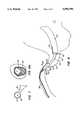
- FIG. 4illustrates placement of the guiding catheter of FIG. 3 with the distal end engaging a coronary ostium according to the present invention.
- FIG. 5is an enlarged view of the distal end of guiding catheter of FIG. 3 within the coronary ostium.
- FIGS. 6A-6Fillustrate the ultrasonic images which would appear on a monitor screen when an ultrasonic imaging catheter is at each of the rotational orientations illustrated by lines A--A through F--F in FIG. 5.
- FIG. 7illustrates the ultrasonic image of FIG. 6B without rotation of the image to a preferred orientation on the screen.
- FIG. 8illustrates a method for therapeutically treating a stenotic region in the coronary vasculature employing a catheter having a cutting element that is introduced through the guiding catheter of FIG. 3.
- FIG. 8Aillustrates the ultrasonic image which would appear on a monitor screen at line A--A of FIG. 8 after the stenotic material has been partially removed and after the cutting catheter of FIG. 8 has been withdrawn.
- Guiding catheters constructed in accordance with the principles of the present inventioncomprise an elongate tube having a proximal end, a distal end, and a lumen extending therebetween.
- the guiding catheterfurther includes a shaped distal tip, such as a bend or a curve in the tube, to facilitate placement of the distal end of the guiding catheter in a coronary ostium.
- the distal tipcan be shaped to accommodate the particular anatomy of the patient. In this way, the guiding catheter can predictably and repeatedly be orientated in a known position within the coronary ostium.
- the tip of the guiding catheterincludes a superior (pointing up) side and an inferior (pointing down) side.
- the top of the guiding catheter tipWhen appropriately positioned, the top of the guiding catheter tip is usually always positioned superior in the ostium of the coronary artery, resulting in the superior side of the guiding catheter being oriented at the top of a fluoroscopic image. In this way, the orientation of the distal end of the guiding catheter is in a known position relative to the patient's vascular anatomy.
- the tube of the guiding cathetermay be composed of a wide variety of biologically compatible materials, typically being made from natural or synthetic polymers, such as silicone, rubber, natural rubber, polyethylene, polyvinylchloride, polyurethanes, polyesters, polytetrafluoroethylenes (PTFE) and the like.
- natural or synthetic polymerssuch as silicone, rubber, natural rubber, polyethylene, polyvinylchloride, polyurethanes, polyesters, polytetrafluoroethylenes (PTFE) and the like.
- PTFEpolytetrafluoroethylenes
- the overall dimensions of the guiding catheterwill depend on use, with the length of the catheters varying widely, typically between about 50 cm and 150 cm, usually being about 100 cm.
- the diameter of the tubemay also vary widely, with the diameter typically being about 1 mm to 4 mm.
- a wide variety of ultrasonically visible markscan be provided including a hole formed in the tube, an ultrasonically opaque material secured on or in the tube (such as paint, a flat piece of metal ribbon, or other low profile material capable of reflecting acoustic energy), or other ultrasound absorbing material such as urethanes, silicone, epoxies, and the like.
- the markis formed near the distal end in a unique position relative to the shaped distal tip.
- the orientation of an ultrasonic image produced within the distal tip of the guiding cathetercan be determined upon visualization of the mark.
- Preferred positions for forming the markinclude the superior and the inferior sides of the guiding catheter tip. Since the superior side of the guiding catheter tip will usually always be positioned superior in the coronary ostium (and since the orientation of the mark relative to the tip is known) the orientation of any ultrasonic image having the mark can easily be correlated with the orientation of the coronary vasculature.
- the image of the markcan simply be rotated to align the image of the mark with the fluoroscopic image of the coronary vasculature.
- an ultrasonic imaging catheteris employed.
- Such ultrasonic imaging cathetersare well known in the art and usually employ an ultrasonic transducer mounted within a distal end of the catheter body and arrange to admit and receive ultrasonic energy within an imaging plane disposed normal to the axial direction of the catheter.
- Exemplary methods of intravascular ultrasoundare described in U.S. Pat. Nos. 4,794,931 and 5,000,185, the disclosures of which are herein incorporated by reference. Such methods include the mechanical rotation of the ultrasonic image transducer about the imaging plane to produce a cross-sectional image of the imaging site.
- the imaging elementBefore the therapeutic element is employed to treat a diseased region, the imaging element must be properly positioned at the treatment site. Positioning of the therapeutic element is accomplished by determining the orientation of the imaging catheter relative to the vascular anatomy while within the guiding catheter as previously described. The imaging catheter is then distally advanced beyond the distal tip of the guiding catheter and toward the diseased region. As the imaging catheter is advanced through the vessel, images are taken to locate the diseased region. The orientation of the resulting images are estimated based on the orientation of the imaging catheter obtained while within the guiding catheter.
- the images produced by the imaging catheterare cross-sectional images of the vascular anatomy.
- the imagesare preferably displayed on a monitor screen so that a physician can view the vascular anatomy while performing the procedure.
- the resulting imagesinclude cross-sectional views of the imaging catheter in addition to the vessel wall.
- the marker at the distal tip of the guiding cathetercomprises a hole in the catheter body
- an ultrasonic image of the markwill appear as a discontinuity in the image of the catheter body at the position of the marker.
- a shadowwill be produced in the ultrasonic image, where the position of the shadow corresponds to the position of the marker on the distal tip of the catheter body.
- the physician viewing the image on the monitorwill be able to correlate the precise rotational orientation of the guiding catheter relative to the features which are revealed in the image.
- the resulting image on the screenshould have the shadow extending toward the top of the screen to have the resulting image in the same orientation as the guiding catheter within the coronary vasculature. If the resulting image is not positioned in such a manner, the invention provides for the rotation of the image on the screen so that it is aligned with the orientation of the guiding catheter within the coronary vasculature.
- the guiding catheter 10includes tubular flexible catheter body 12 having a proximal end 14 and a distal end 16.
- a proximal housing 18 having a hemostasis valveis generally secured to the proximal end 14 of the catheter body 12 and includes a side port 20 for injecting fluids, such as saline and contrast media, into the guiding catheter 10.
- a shaped distal tip 22At the distal end 16 is a shaped distal tip 22.
- the distal tip 22is shaped according to the particular features of the patient's vascular anatomy in order to facilitate predictable and repeatable placement of the distal end 16 into a coronary ostium.
- a hole 24serves as an ultrasonic reference marker which appears as a discontinuity in the image of the catheter body 12 when viewed from within the guiding catheter 10 by an ultrasonic imaging catheter.
- FIG. 3An alternative embodiment of the distal tip 22 is shown in FIG. 3 and includes a thin strip of acoustically reflective material 26 as the ultrasonic reference marker.
- the strip 26produces a shadow in the ultrasonic image of the vascular anatomy produced by the imaging catheter.
- the marker 24is shown on a superior side 28 of the catheter body 12.
- the hole 24is located superior in the coronary ostium.
- the hole 24(or strip 26) can be formed at other unique positions at the distal tip 22, such as at an inferior side 30 of the catheter body 12. Since the distal tip 22 is fashioned to be received into the coronary ostium at a known and repeatable position, unique positioning of the hole 24 on the distal tip 22 provides for a known position of the hole 24 relative to the coronary vasculature when the distal tip 22 is received in the coronary ostium.
- a large guidewire(not shown) is introduced into the aorta 34.
- fluoroscopic imagingis employed to assist in the positioning of the guidewire.
- the guiding catheter 10is advanced over the guidewire until the distal tip 22 is beyond the distal tip of the guidewire.
- the shaped distal tip 22allows the guiding catheter 10 to be received in the coronary ostium 36 at a known position.
- the physicianwill torque and advance the guiding catheter 10 until it "pops" into the appropriate coronary ostium 36.
- the strip 26is on the superior side 28 of the catheter body 12 and is received superior in the coronary ostium 36. In this manner, both the catheter body 12 and the strip 26 are in a known position relative to the coronary vasculature.
- a coronary guidewire 32is delivered into the coronary artery through the guiding catheter 10.
- An imaging catheter 38is then introduced through the guiding catheter 10, typically over the guidewire 32.
- the imaging catheter 38includes a cable 40 for rotating the ultrasonic transducer (not shown) in the catheter 38.
- a phased array catheter systemcan be employed to image the vessel walls.
- FIGS. 6A-6Fillustrate monitor images produced by the imaging catheter 38 at lines A--A through F--F of FIG. 5, respectively.
- the ultrasonic image produced within the guiding catheter 10reveals the imaging catheter 38 and the guide catheter body 12.
- the cross-sectional image produced by the imaging catheter 38 when intersecting the strip 26is shown in FIG. 6B.
- the resulting imagereveals the imaging catheter 38 and the catheter body 12.
- the image of the strip 26appears as an acoustic vector 42 extending from the image of the outside catheter wall (much like a lighthouse beacon).
- FIG. 6Aillustrate monitor images produced by the imaging catheter 38 at lines A--A through F--F of FIG. 5, respectively.
- the ultrasonic image produced within the guiding catheter 10reveals the imaging catheter 38 and the guide catheter body 12.
- the cross-sectional image produced by the imaging catheter 38 when intersecting the strip 26is shown in FIG. 6B.
- the resulting imagereveals the imaging catheter 38 and the catheter body 12.
- the image of the strip 26appears
- the vector 42extends toward the top of the screen and is therefore aligned with the actual orientation of the strip 26 within the coronary ostium 36.
- a physician viewing the screen of FIG. 6Bwould have a view of the distal tip 22 in the same spatial orientation as the distal tip 22 held within the coronary ostium 36.
- the vector 42is not aligned with the actual orientation of the distal tip 22 within the coronary ostium 36.
- the image on the screencan optionally be rotated with a software program until the shadow 42 is aligned with the known position (in this case superior) of the strip 26 and distal tip 22 in the coronary ostium 36.
- FIG. 6Cthe image produced by the imaging catheter 38 when advanced distally beyond the distal end 16 of the catheter body 12 is shown.
- the imageincludes an image of the imaging catheter 38, the annular vessel wall 43 of the proximal coronary artery, which typically appears in three layer structure, and an annular ring of plaque 44 built up on the interior walls of the proximal coronary artery.
- an amount of eccentric plaque 46exists in the coronary artery as shown in FIG. 6D.
- the eccentric plaque 46is located inferior in the coronary artery, opposite the position of the strip 26 in the coronary ostium 36.
- the image of the strip 36 obtained while in the guiding catheter 10is used to estimate the position of the eccentric plaque 46 within the coronary artery since the imaging catheter 38 is advanced just distal, usually only 1 mm to 30 mm from the strip 26.
- the distal tip 22experiences little or no rotation within the coronary artery, thereby insuring that the image produced at position D--D is at substantially the same rotational position as the image attained at position B--B.
- the length of the eccentric plaque 46is determined by producing images along the coronary artery until the plaque 44 once again becomes annularly disposed about the coronary artery as shown in FIG. 6E, or totally disappears as shown in FIG. 6F.
- the imaging catheter 38is distally advanced beyond the distal end 16 of the catheter body 12 to visualize the coronary artery.
- the imaging catheter 38is advanced through the coronary artery until reaching the plaque 46 as shown in FIG. 6D.
- the rotational orientation of the imaging catheter 38will usually remain virtually unchanged.
- the position of the imaging catheter 39 relative to the plaque 46will be known.
- the actual orientation of the plaque 46 in the arterycan be determined. Once the actual orientation of the plaque is known, the imaging catheter 38 is withdrawn from the coronary artery and an atherectomy catheter 39 is introduced over the guidewire.
- the atherectomy catheter 39includes a canoe-shaped housing 48 having an aperture 50 therein. Within the aperture 50 is a cutting element 52 which is employed to shave the plaque 46 from the walls of the coronary artery. A balloon 54 is provided on the housing 48 opposite the aperture 50 for forcing the cutting element 52 against the plaque 46 when inflated.
- the position of the cutter 52 on the atherectomy catheter 39can be manipulated to ensure that it is facing the eccentric plaque 46, based on the known orientation of the plaque from the previous ultrasound image. If the cutting element 52 is not adjacent the plaque 46, the atherectomy catheter 39 can be rotated from its proximal end (which is outside the patient) to adjust the rotational position of the cutting element 52.
- the balloon 54When at the proper location, the balloon 54 is inflated and the cutting element 52 is actuated to remove the plaque 46 from the coronary artery. After removal of the plaque 46, imaging of the area can again occur (as illustrated in FIG. 8A) to determine if sufficient plaque 46 has been removed.
- the inventioncan be used to image and therapeutic treat other areas of the vascular anatomy, such as the left coronary artery or other vessels.
- the methods of the present inventionare particularly useful in the right coronary artery because no branches or other land marks exist in the right coronary ostium to assist in the correlation of the ultrasonic image to the angiographic image.
Landscapes
- Health & Medical Sciences (AREA)
- Life Sciences & Earth Sciences (AREA)
- Animal Behavior & Ethology (AREA)
- Biophysics (AREA)
- Veterinary Medicine (AREA)
- Public Health (AREA)
- General Health & Medical Sciences (AREA)
- Engineering & Computer Science (AREA)
- Biomedical Technology (AREA)
- Heart & Thoracic Surgery (AREA)
- Pathology (AREA)
- Molecular Biology (AREA)
- Surgery (AREA)
- Medical Informatics (AREA)
- Radiology & Medical Imaging (AREA)
- Physics & Mathematics (AREA)
- Nuclear Medicine, Radiotherapy & Molecular Imaging (AREA)
- Pulmonology (AREA)
- Anesthesiology (AREA)
- Hematology (AREA)
- Ultra Sonic Daignosis Equipment (AREA)
- Media Introduction/Drainage Providing Device (AREA)
Abstract
Description
Claims (22)
Priority Applications (7)
| Application Number | Priority Date | Filing Date | Title |
|---|---|---|---|
| US08/470,673US5596990A (en) | 1995-06-06 | 1995-06-06 | Rotational correlation of intravascular ultrasound image with guide catheter position |
| CA002223171ACA2223171A1 (en) | 1995-06-06 | 1996-05-20 | Rotational correlation of intravascular ultrasound image with guide catheter position |
| PCT/US1996/007360WO1996039081A1 (en) | 1995-06-06 | 1996-05-20 | Rotational correlation of intravascular ultrasound image with guide catheter position |
| EP96916525AEP0836421A4 (en) | 1995-06-06 | 1996-05-20 | Rotational correlation of intravascular ultrasound image with guide catheter position |
| JP9500639AJPH11506628A (en) | 1995-06-06 | 1996-05-20 | Rotational correlation between intravascular ultrasound image and guide catheter position |
| US08/708,386US5724977A (en) | 1995-06-06 | 1996-09-04 | Rotational correlation of intravascular ultrasound image with guide catheter position |
| US08/954,278US5879305A (en) | 1995-06-06 | 1997-10-20 | Rotational correlation of intravascular ultrasound image with guide catheter position |
Applications Claiming Priority (1)
| Application Number | Priority Date | Filing Date | Title |
|---|---|---|---|
| US08/470,673US5596990A (en) | 1995-06-06 | 1995-06-06 | Rotational correlation of intravascular ultrasound image with guide catheter position |
Related Child Applications (1)
| Application Number | Title | Priority Date | Filing Date |
|---|---|---|---|
| US08/708,386ContinuationUS5724977A (en) | 1995-06-06 | 1996-09-04 | Rotational correlation of intravascular ultrasound image with guide catheter position |
Publications (1)
| Publication Number | Publication Date |
|---|---|
| US5596990Atrue US5596990A (en) | 1997-01-28 |
Family
ID=23868552
Family Applications (3)
| Application Number | Title | Priority Date | Filing Date |
|---|---|---|---|
| US08/470,673Expired - LifetimeUS5596990A (en) | 1995-06-06 | 1995-06-06 | Rotational correlation of intravascular ultrasound image with guide catheter position |
| US08/708,386Expired - Fee RelatedUS5724977A (en) | 1995-06-06 | 1996-09-04 | Rotational correlation of intravascular ultrasound image with guide catheter position |
| US08/954,278Expired - LifetimeUS5879305A (en) | 1995-06-06 | 1997-10-20 | Rotational correlation of intravascular ultrasound image with guide catheter position |
Family Applications After (2)
| Application Number | Title | Priority Date | Filing Date |
|---|---|---|---|
| US08/708,386Expired - Fee RelatedUS5724977A (en) | 1995-06-06 | 1996-09-04 | Rotational correlation of intravascular ultrasound image with guide catheter position |
| US08/954,278Expired - LifetimeUS5879305A (en) | 1995-06-06 | 1997-10-20 | Rotational correlation of intravascular ultrasound image with guide catheter position |
Country Status (5)
| Country | Link |
|---|---|
| US (3) | US5596990A (en) |
| EP (1) | EP0836421A4 (en) |
| JP (1) | JPH11506628A (en) |
| CA (1) | CA2223171A1 (en) |
| WO (1) | WO1996039081A1 (en) |
Cited By (55)
| Publication number | Priority date | Publication date | Assignee | Title |
|---|---|---|---|---|
| US5771895A (en)* | 1996-02-12 | 1998-06-30 | Slager; Cornelis J. | Catheter for obtaining three-dimensional reconstruction of a vascular lumen and wall |
| US5830145A (en)* | 1996-09-20 | 1998-11-03 | Cardiovascular Imaging Systems, Inc. | Enhanced accuracy of three-dimensional intraluminal ultrasound (ILUS) image reconstruction |
| US5879305A (en)* | 1995-06-06 | 1999-03-09 | Cardiovascular Imaging Systems, Inc. | Rotational correlation of intravascular ultrasound image with guide catheter position |
| US5902245A (en)* | 1986-02-28 | 1999-05-11 | Cardiovascular Imaging Systems, Inc. | Method and apparatus for intravascular ultrasonography |
| WO1999039628A1 (en) | 1998-02-10 | 1999-08-12 | Emory University | Systems and methods for providing radiation therapy and catheter guides |
| WO1999049910A3 (en)* | 1998-03-31 | 2000-02-17 | Transvascular Inc | Transvascular catheters having imaging transducers |
| US6248075B1 (en)* | 1997-09-26 | 2001-06-19 | Ep Technologies, Inc. | Method and apparatus for fixing the anatomical orientation of a displayed ultrasound generated image |
| US6283951B1 (en)* | 1996-10-11 | 2001-09-04 | Transvascular, Inc. | Systems and methods for delivering drugs to selected locations within the body |
| US6287322B1 (en)* | 1995-12-07 | 2001-09-11 | Loma Linda University Medical Center | Tissue opening locator and everter and method |
| US6327490B1 (en) | 1998-02-27 | 2001-12-04 | Varian Medical Systems, Inc. | Brachytherapy system for prostate cancer treatment with computer implemented systems and processes to facilitate pre-implantation planning and post-implantation evaluations with storage of multiple plan variations for a single patient |
| US6360116B1 (en) | 1998-02-27 | 2002-03-19 | Varian Medical Systems, Inc. | Brachytherapy system for prostate cancer treatment with computer implemented systems and processes to facilitate pre-operative planning and post-operative evaluations |
| US6375615B1 (en) | 1995-10-13 | 2002-04-23 | Transvascular, Inc. | Tissue penetrating catheters having integral imaging transducers and their methods of use |
| US6398737B2 (en)* | 1999-01-13 | 2002-06-04 | Scimed Life Systems, Inc. | Safety mechanism and methods to prevent rotating imaging device from exiting a catheter |
| US6607488B1 (en)* | 2000-03-02 | 2003-08-19 | Acuson Corporation | Medical diagnostic ultrasound system and method for scanning plane orientation |
| US20040010216A1 (en)* | 2000-02-24 | 2004-01-15 | Zhu Yong Hua | Device for closing tissue openings |
| US6719700B1 (en) | 2002-12-13 | 2004-04-13 | Scimed Life Systems, Inc. | Ultrasound ranging for localization of imaging transducer |
| US20040092821A1 (en)* | 2000-11-24 | 2004-05-13 | Steffen Hering | Ultrasonic probe with positioning device for examination devices and operation devices |
| US20040186368A1 (en)* | 2003-03-21 | 2004-09-23 | Scimed Life Systems, Inc. | Systems and methods for internal tissue penetration |
| US20040193057A1 (en)* | 2003-03-28 | 2004-09-30 | Scimed Life Systems, Inc. | Imaging transducer assembly |
| US20050085727A1 (en)* | 2001-01-25 | 2005-04-21 | Swanborn Rebecca L. | Method and device for marking skin during an ultrasound examination |
| US20050095275A1 (en)* | 2003-09-05 | 2005-05-05 | Zhu Yong H. | Dressing delivery system for internal wounds |
| US20050106806A1 (en)* | 2003-11-13 | 2005-05-19 | Fred Fishburn | Methods of forming a double-sided capacitor or a contact using a sacrificial structure |
| US20060173350A1 (en)* | 2005-01-11 | 2006-08-03 | Scimed Life Systems, Inc. | Systems and methods for three dimensional imaging with an orientation adjustable array |
| US20070167708A1 (en)* | 2005-10-12 | 2007-07-19 | Brainlab Ag | Marker for a navigation system and method for detecting a marker |
| US20070225605A1 (en)* | 2001-01-25 | 2007-09-27 | Swanbom Rebecca L | Method and Device for Marking Skin During an Ultrasound Examination |
| US20080154345A1 (en)* | 2006-12-26 | 2008-06-26 | Spectranetics | Multi-Port Light Delivery Catheter And Methods For The Use Thereof |
| US20080221440A1 (en)* | 2007-03-08 | 2008-09-11 | Sync-Rx, Ltd. | Imaging and tools for use with moving organs |
| US20090306547A1 (en)* | 2007-03-08 | 2009-12-10 | Sync-Rx, Ltd. | Stepwise advancement of a medical tool |
| US20100160773A1 (en)* | 2007-03-08 | 2010-06-24 | Sync-Rx, Ltd. | Automatic quantitative vessel analysis at the location of an automatically-detected tool |
| US20110054503A1 (en)* | 2009-09-02 | 2011-03-03 | Isa Rizk | Systems, methods and devices for ablation, crossing, and cutting of occlusions |
| US20140276063A1 (en)* | 2013-03-13 | 2014-09-18 | Volcano Corporation | Systems and methods for producing an image from a rotational intravascular ultrasound device |
| US8855744B2 (en) | 2008-11-18 | 2014-10-07 | Sync-Rx, Ltd. | Displaying a device within an endoluminal image stack |
| US8956376B2 (en) | 2011-06-30 | 2015-02-17 | The Spectranetics Corporation | Reentry catheter and method thereof |
| US8998936B2 (en) | 2011-06-30 | 2015-04-07 | The Spectranetics Corporation | Reentry catheter and method thereof |
| US9095313B2 (en) | 2008-11-18 | 2015-08-04 | Sync-Rx, Ltd. | Accounting for non-uniform longitudinal motion during movement of an endoluminal imaging probe |
| US9101286B2 (en) | 2008-11-18 | 2015-08-11 | Sync-Rx, Ltd. | Apparatus and methods for determining a dimension of a portion of a stack of endoluminal data points |
| US9144394B2 (en) | 2008-11-18 | 2015-09-29 | Sync-Rx, Ltd. | Apparatus and methods for determining a plurality of local calibration factors for an image |
| US9305334B2 (en) | 2007-03-08 | 2016-04-05 | Sync-Rx, Ltd. | Luminal background cleaning |
| US9375164B2 (en) | 2007-03-08 | 2016-06-28 | Sync-Rx, Ltd. | Co-use of endoluminal data and extraluminal imaging |
| US9572694B2 (en) | 2003-03-18 | 2017-02-21 | Veryan Medical Limited | Helical graft |
| US9597214B2 (en) | 2008-10-10 | 2017-03-21 | Kevin Heraty | Medical device |
| US9629571B2 (en) | 2007-03-08 | 2017-04-25 | Sync-Rx, Ltd. | Co-use of endoluminal data and extraluminal imaging |
| US9636082B2 (en) | 2001-08-24 | 2017-05-02 | The Cooper Companies Global Holdings Lp | Medical-surgical devices |
| US9814862B2 (en) | 2011-06-30 | 2017-11-14 | The Spectranetics Corporation | Reentry catheter and method thereof |
| US9888969B2 (en) | 2007-03-08 | 2018-02-13 | Sync-Rx Ltd. | Automatic quantitative vessel analysis |
| US9974509B2 (en) | 2008-11-18 | 2018-05-22 | Sync-Rx Ltd. | Image super enhancement |
| US10045756B2 (en) | 2003-03-29 | 2018-08-14 | The Cooper Companies Global Holdings Lp | Medical devices |
| US10362962B2 (en) | 2008-11-18 | 2019-07-30 | Synx-Rx, Ltd. | Accounting for skipped imaging locations during movement of an endoluminal imaging probe |
| CN110200654A (en)* | 2018-02-28 | 2019-09-06 | 斯波瑞申有限公司(以奥林巴斯呼吸美国名义) | Orientation pins for devices using radial ultrasound |
| US10716528B2 (en) | 2007-03-08 | 2020-07-21 | Sync-Rx, Ltd. | Automatic display of previously-acquired endoluminal images |
| US10748289B2 (en) | 2012-06-26 | 2020-08-18 | Sync-Rx, Ltd | Coregistration of endoluminal data points with values of a luminal-flow-related index |
| US11064964B2 (en) | 2007-03-08 | 2021-07-20 | Sync-Rx, Ltd | Determining a characteristic of a lumen by measuring velocity of a contrast agent |
| US11064903B2 (en) | 2008-11-18 | 2021-07-20 | Sync-Rx, Ltd | Apparatus and methods for mapping a sequence of images to a roadmap image |
| US11197651B2 (en) | 2007-03-08 | 2021-12-14 | Sync-Rx, Ltd. | Identification and presentation of device-to-vessel relative motion |
| US20220280244A1 (en)* | 2019-05-31 | 2022-09-08 | Tva Medical, Inc. | Systems, methods, and catheters for endovascular treatment of a blood vessel |
Families Citing this family (108)
| Publication number | Priority date | Publication date | Assignee | Title |
|---|---|---|---|---|
| DE69633411T2 (en) | 1995-10-13 | 2005-10-20 | Transvascular, Inc., Menlo Park | METHOD AND DEVICE FOR PREVENTING ARTERIAL ATTRACTIONS AND / OR FOR CARRYING OUT OTHER TRANSVASCULAR INTERVENTIONS |
| ATE440559T1 (en) | 1995-10-13 | 2009-09-15 | Medtronic Vascular Inc | DEVICE FOR INTERSTITIAL TRANSVASCULAR PROCEDURES |
| US6302875B1 (en)* | 1996-10-11 | 2001-10-16 | Transvascular, Inc. | Catheters and related devices for forming passageways between blood vessels or other anatomical structures |
| CA2246332C (en)* | 1996-02-15 | 2009-04-14 | Biosense, Inc. | Catheter based surgery |
| DE69723137T2 (en)* | 1996-03-18 | 2004-05-27 | Ashiya, Hiroaki | Catheteranordnung |
| JP3367339B2 (en)* | 1996-07-01 | 2003-01-14 | ペンタックス株式会社 | Medical probe guidance device |
| US7341598B2 (en) | 1999-01-13 | 2008-03-11 | Boston Scientific Scimed, Inc. | Stent with protruding branch portion for bifurcated vessels |
| US6599316B2 (en) | 1996-11-04 | 2003-07-29 | Advanced Stent Technologies, Inc. | Extendible stent apparatus |
| US6325826B1 (en) | 1998-01-14 | 2001-12-04 | Advanced Stent Technologies, Inc. | Extendible stent apparatus |
| US6692483B2 (en) | 1996-11-04 | 2004-02-17 | Advanced Stent Technologies, Inc. | Catheter with attached flexible side sheath |
| US6835203B1 (en) | 1996-11-04 | 2004-12-28 | Advanced Stent Technologies, Inc. | Extendible stent apparatus |
| EP1723931B1 (en)* | 1996-11-04 | 2012-01-04 | Advanced Stent Technologies, Inc. | Extendible stent apparatus and method for deploying the same |
| US8211167B2 (en) | 1999-12-06 | 2012-07-03 | Boston Scientific Scimed, Inc. | Method of using a catheter with attached flexible side sheath |
| US7220275B2 (en)* | 1996-11-04 | 2007-05-22 | Advanced Stent Technologies, Inc. | Stent with protruding branch portion for bifurcated vessels |
| US7591846B2 (en) | 1996-11-04 | 2009-09-22 | Boston Scientific Scimed, Inc. | Methods for deploying stents in bifurcations |
| US6095976A (en)* | 1997-06-19 | 2000-08-01 | Medinol Ltd. | Method for enhancing an image derived from reflected ultrasound signals produced by an ultrasound transmitter and detector inserted in a bodily lumen |
| US5951480A (en)* | 1997-09-29 | 1999-09-14 | Boston Scientific Corporation | Ultrasound imaging guidewire with static central core and tip |
| US6078831A (en)* | 1997-09-29 | 2000-06-20 | Scimed Life Systems, Inc. | Intravascular imaging guidewire |
| CA2305375C (en)* | 1997-09-29 | 2007-10-09 | Scimed Life Systems, Inc. | Intravascular imaging guidewire |
| US6780199B2 (en) | 1998-05-15 | 2004-08-24 | Advanced Cardiovascular Systems, Inc. | Enhanced stent delivery system |
| US6447501B1 (en) | 1998-05-15 | 2002-09-10 | X Technologies Inc. | Enhanced stent delivery system |
| CA2330134A1 (en) | 1998-05-15 | 1999-11-25 | Medgination, Inc. | Enhanced balloon dilatation system |
| US6740104B1 (en) | 1998-05-15 | 2004-05-25 | Advanced Cardiovascular Systems, Inc. | Enhanced catheter with alignment means |
| US6295680B1 (en)* | 1998-07-05 | 2001-10-02 | The Regents Of The University Of Michigan | Method for detecting early atherosclerosis and vascular damage using radioactive tracers and intravascular radiation detection devices |
| US20050060027A1 (en)* | 1999-01-13 | 2005-03-17 | Advanced Stent Technologies, Inc. | Catheter balloon systems and methods |
| US7655030B2 (en) | 2003-07-18 | 2010-02-02 | Boston Scientific Scimed, Inc. | Catheter balloon systems and methods |
| US7387639B2 (en)* | 1999-06-04 | 2008-06-17 | Advanced Stent Technologies, Inc. | Short sleeve stent delivery catheter and methods |
| US6884258B2 (en) | 1999-06-04 | 2005-04-26 | Advanced Stent Technologies, Inc. | Bifurcation lesion stent delivery using multiple guidewires |
| US6299622B1 (en) | 1999-08-19 | 2001-10-09 | Fox Hollow Technologies, Inc. | Atherectomy catheter with aligned imager |
| US7708749B2 (en) | 2000-12-20 | 2010-05-04 | Fox Hollow Technologies, Inc. | Debulking catheters and methods |
| US8328829B2 (en)* | 1999-08-19 | 2012-12-11 | Covidien Lp | High capacity debulking catheter with razor edge cutting window |
| US7713279B2 (en) | 2000-12-20 | 2010-05-11 | Fox Hollow Technologies, Inc. | Method and devices for cutting tissue |
| US6689156B1 (en)* | 1999-09-23 | 2004-02-10 | Advanced Stent Technologies, Inc. | Stent range transducers and methods of use |
| WO2001021081A1 (en) | 1999-09-24 | 2001-03-29 | Cook Urological Inc. | Embryo transfer catheter |
| US6546271B1 (en)* | 1999-10-01 | 2003-04-08 | Bioscience, Inc. | Vascular reconstruction |
| JP4080874B2 (en) | 2000-12-20 | 2008-04-23 | フォックス ハロウ テクノロジーズ,インコーポレイティド | Bulking catheter |
| US7245959B1 (en)* | 2001-03-02 | 2007-07-17 | Scimed Life Systems, Inc. | Imaging catheter for use inside a guiding catheter |
| US8617231B2 (en) | 2001-05-18 | 2013-12-31 | Boston Scientific Scimed, Inc. | Dual guidewire exchange catheter system |
| JP4018450B2 (en)* | 2002-05-27 | 2007-12-05 | キヤノン株式会社 | Document management system, document management apparatus, authentication method, computer readable program, and storage medium |
| US9949829B2 (en) | 2002-06-13 | 2018-04-24 | Ancora Heart, Inc. | Delivery devices and methods for heart valve repair |
| US8641727B2 (en) | 2002-06-13 | 2014-02-04 | Guided Delivery Systems, Inc. | Devices and methods for heart valve repair |
| US20050107811A1 (en) | 2002-06-13 | 2005-05-19 | Guided Delivery Systems, Inc. | Delivery devices and methods for heart valve repair |
| US20060122633A1 (en) | 2002-06-13 | 2006-06-08 | John To | Methods and devices for termination |
| AU2003249309A1 (en)* | 2002-07-24 | 2004-02-09 | Advanced Stent Technologies, Inc. | Stents capable of controllably releasing histone deacetylase inhibitors |
| CN100539949C (en)* | 2002-10-10 | 2009-09-16 | 视声公司 | High Frequency, High Frame Rate Ultrasound Imaging System |
| JP4713339B2 (en)* | 2002-10-10 | 2011-06-29 | ビジュアルソニックス インコーポレイティド | High frequency high frame rate ultrasound imaging system |
| US7797057B2 (en) | 2002-10-23 | 2010-09-14 | Medtronic, Inc. | Medical paddle lead and method for spinal cord stimulation |
| US8246640B2 (en) | 2003-04-22 | 2012-08-21 | Tyco Healthcare Group Lp | Methods and devices for cutting tissue at a vascular location |
| US7909766B2 (en)* | 2003-05-21 | 2011-03-22 | Scimed Life Systems, Inc. | Systems and methods for improving the imaging resolution of an imaging transducer |
| US8298280B2 (en)* | 2003-08-21 | 2012-10-30 | Boston Scientific Scimed, Inc. | Stent with protruding branch portion for bifurcated vessels |
| US7344557B2 (en)* | 2003-11-12 | 2008-03-18 | Advanced Stent Technologies, Inc. | Catheter balloon systems and methods |
| US7637904B2 (en)* | 2003-12-19 | 2009-12-29 | Vance Products Incorporated | Catheter with snap on feature |
| US7842289B2 (en)* | 2003-12-24 | 2010-11-30 | Aduro Biotech | Recombinant nucleic acid molecules, expression cassettes, and bacteria, and methods of use thereof |
| EP1728098A2 (en)* | 2004-03-01 | 2006-12-06 | Sunnybrook and Women's College Health Sciences Centre | System and method for ecg-triggered retrospective color flow ultrasound imaging |
| US7618374B2 (en)* | 2004-09-27 | 2009-11-17 | Siemens Medical Solutions Usa, Inc. | Image plane sensing methods and systems for intra-patient probes |
| US20060111704A1 (en)* | 2004-11-22 | 2006-05-25 | Rox Medical, Inc. | Devices, systems, and methods for energy assisted arterio-venous fistula creation |
| US7892177B2 (en)* | 2005-02-28 | 2011-02-22 | Scimed Life Systems, Inc. | Systems and methods for estimating the length and position of a stent to be applied within a patient |
| AU2006247571A1 (en)* | 2005-05-13 | 2006-11-23 | Cook Incorporated | Medical device delivery systems that facilitate medical device placement in the presence of ultrasonic waves |
| US8608789B2 (en)* | 2005-05-24 | 2013-12-17 | Trireme Medical, Inc. | Delivery system for bifurcation stents |
| DE102005030647B3 (en)* | 2005-06-30 | 2007-03-22 | Siemens Ag | Apparatus and method for intraluminal imaging for the reconstruction of 3D image data sets |
| US8821561B2 (en)* | 2006-02-22 | 2014-09-02 | Boston Scientific Scimed, Inc. | Marker arrangement for bifurcation catheter |
| US20070276419A1 (en) | 2006-05-26 | 2007-11-29 | Fox Hollow Technologies, Inc. | Methods and devices for rotating an active element and an energy emitter on a catheter |
| DE102006046045B4 (en)* | 2006-09-28 | 2014-05-28 | Siemens Aktiengesellschaft | Method for two-dimensional or three-dimensional imaging of a target area of interest in a hollow organ and medical examination and treatment system |
| US20080147174A1 (en)* | 2006-12-11 | 2008-06-19 | Trireme Medical, Inc. | Apparatus and method of using markers to position stents in bifurcations |
| US20080275481A1 (en)* | 2007-05-04 | 2008-11-06 | Scarpone Michael A | Ultrasound guided percutaneous cutting tool with gradations and adjustable stop ring |
| US8311613B2 (en) | 2007-06-20 | 2012-11-13 | Siemens Aktiengesellschaft | Electrode catheter positioning system |
| US8486134B2 (en) | 2007-08-01 | 2013-07-16 | Boston Scientific Scimed, Inc. | Bifurcation treatment system and methods |
| US8825134B2 (en)* | 2007-09-14 | 2014-09-02 | Siemens Aktiengesellschaft | Catheter localization system |
| US9125632B2 (en) | 2007-10-19 | 2015-09-08 | Guided Delivery Systems, Inc. | Systems and methods for cardiac remodeling |
| US8747456B2 (en) | 2007-12-31 | 2014-06-10 | Boston Scientific Scimed, Inc. | Bifurcation stent delivery system and methods |
| US8790367B2 (en) | 2008-02-06 | 2014-07-29 | Guided Delivery Systems Inc. | Multi-window guide tunnel |
| US8784440B2 (en) | 2008-02-25 | 2014-07-22 | Covidien Lp | Methods and devices for cutting tissue |
| US8377108B2 (en) | 2008-06-02 | 2013-02-19 | Boston Scientific Scimed, Inc. | Staggered two balloon bifurcation catheter assembly and methods |
| WO2009149405A1 (en)* | 2008-06-05 | 2009-12-10 | Boston Scientific Scimed, Inc. | Balloon bifurcated lumen treatment |
| JP5662310B2 (en)* | 2008-06-05 | 2015-01-28 | ボストン サイエンティフィック サイムド,インコーポレイテッドBoston Scientific Scimed,Inc. | Shrinkable branch device and method of manufacturing the same |
| JP5454844B2 (en) | 2008-08-13 | 2014-03-26 | 株式会社東芝 | Ultrasonic diagnostic apparatus, ultrasonic image display apparatus, and ultrasonic image display program |
| US20100130835A1 (en)* | 2008-09-30 | 2010-05-27 | Rox Medical, Inc. | Methods for screening and treating patients with compromised cardiopulmonary function |
| WO2010041038A1 (en)* | 2008-10-10 | 2010-04-15 | Veryan Medical Limited | A medical device |
| US8414604B2 (en) | 2008-10-13 | 2013-04-09 | Covidien Lp | Devices and methods for manipulating a catheter shaft |
| CN102625673B (en) | 2009-04-29 | 2014-12-24 | 泰科保健集团有限合伙公司 | Methods and devices for cutting and abrading tissue |
| WO2010132748A1 (en) | 2009-05-14 | 2010-11-18 | Fox Hollow Technologies, Inc. | Easily cleaned atherectomy catheters and methods of use |
| US20100305442A1 (en)* | 2009-05-29 | 2010-12-02 | Boston Scientific Scimed, Inc. | Systems and methods for implementing a data management system for catheter-based imaging systems |
| WO2011068932A1 (en) | 2009-12-02 | 2011-06-09 | Fox Hollow Technologies, Inc. | Methods and devices for cutting tissue |
| CN102695463B (en) | 2009-12-11 | 2015-01-14 | 泰科保健集团有限合伙公司 | Material removal device having improved material capture efficiency and methods of use |
| RU2538174C2 (en) | 2010-06-14 | 2015-01-10 | Ковидиен Лп | Device for material removal |
| WO2012031204A2 (en) | 2010-09-03 | 2012-03-08 | Guided Delivery Systems Inc. | Devices and methods for anchoring tissue |
| CA2815186C (en) | 2010-10-28 | 2015-12-29 | Covidien Lp | Material removal device and method of use |
| KR20150020240A (en) | 2010-11-11 | 2015-02-25 | 코비디엔 엘피 | Flexible debulking catheters with imaging and methods of use and manufacture |
| EP2750862B1 (en) | 2011-09-01 | 2016-07-06 | Covidien LP | Catheter with helical drive shaft and methods of manufacture |
| EP3281608B1 (en) | 2012-02-10 | 2020-09-16 | CVDevices, LLC | Medical product comprising a frame and visceral pleura |
| US9532844B2 (en) | 2012-09-13 | 2017-01-03 | Covidien Lp | Cleaning device for medical instrument and method of use |
| US9943329B2 (en) | 2012-11-08 | 2018-04-17 | Covidien Lp | Tissue-removing catheter with rotatable cutter |
| CA2900862C (en) | 2013-02-11 | 2017-10-03 | Cook Medical Technologies Llc | Expandable support frame and medical device |
| JP6059334B2 (en)* | 2013-03-04 | 2017-01-11 | テルモ株式会社 | Diagnostic imaging apparatus, information processing apparatus, operating method thereof, program, and computer-readable storage medium |
| US20150305612A1 (en) | 2014-04-23 | 2015-10-29 | Mark Hunter | Apparatuses and methods for registering a real-time image feed from an imaging device to a steerable catheter |
| US20150305650A1 (en) | 2014-04-23 | 2015-10-29 | Mark Hunter | Apparatuses and methods for endobronchial navigation to and confirmation of the location of a target tissue and percutaneous interception of the target tissue |
| WO2015171602A1 (en)* | 2014-05-07 | 2015-11-12 | Muffin Incorporated | Guide members and associated apparatuses useful for intravascular ultrasound procedures |
| WO2015200702A1 (en) | 2014-06-27 | 2015-12-30 | Covidien Lp | Cleaning device for catheter and catheter including the same |
| US10617847B2 (en) | 2014-11-04 | 2020-04-14 | Orbusneich Medical Pte. Ltd. | Variable flexibility catheter support frame |
| EP4008389B1 (en) | 2014-11-04 | 2025-07-02 | OrbusNeich Medical Pte. Ltd. | Progressive flexibility catheter support frame |
| US10314667B2 (en) | 2015-03-25 | 2019-06-11 | Covidien Lp | Cleaning device for cleaning medical instrument |
| AU2016260305B2 (en) | 2015-05-12 | 2022-01-06 | Ancora Heart, Inc. | Device and method for releasing catheters from cardiac structures |
| US10292721B2 (en) | 2015-07-20 | 2019-05-21 | Covidien Lp | Tissue-removing catheter including movable distal tip |
| US10314664B2 (en) | 2015-10-07 | 2019-06-11 | Covidien Lp | Tissue-removing catheter and tissue-removing element with depth stop |
| US10667914B2 (en) | 2016-11-18 | 2020-06-02 | Ancora Heart, Inc. | Myocardial implant load sharing device and methods to promote LV function |
| US11672524B2 (en) | 2019-07-15 | 2023-06-13 | Ancora Heart, Inc. | Devices and methods for tether cutting |
| EP4017384A1 (en) | 2019-08-22 | 2022-06-29 | Edwards Lifesciences Corporation | Puncture needles |
| CR20220218A (en) | 2019-11-14 | 2022-08-22 | Edwards Lifesciences Corp | Transcatheter medical implant delivery |
Citations (6)
| Publication number | Priority date | Publication date | Assignee | Title |
|---|---|---|---|---|
| US4325257A (en)* | 1980-02-20 | 1982-04-20 | Kino Gordon S | Real-time digital, synthetic-focus, acoustic imaging system |
| US4817613A (en)* | 1987-07-13 | 1989-04-04 | Devices For Vascular Intervention, Inc. | Guiding catheter |
| US5054492A (en)* | 1990-12-17 | 1991-10-08 | Cardiovascular Imaging Systems, Inc. | Ultrasonic imaging catheter having rotational image correlation |
| US5163921A (en)* | 1990-10-04 | 1992-11-17 | Feiring Andrew J | Valved perfusion cardiovascular catheters |
| US5318032A (en)* | 1992-02-05 | 1994-06-07 | Devices For Vascular Intervention | Guiding catheter having soft tip |
| US5485845A (en)* | 1995-05-04 | 1996-01-23 | Hewlett Packard Company | Rotary encoder for intravascular ultrasound catheter |
Family Cites Families (17)
| Publication number | Priority date | Publication date | Assignee | Title |
|---|---|---|---|---|
| US3873656A (en)* | 1967-12-15 | 1975-03-25 | Ici Ltd | Production of laminar articles |
| GB1369744A (en)* | 1973-05-03 | 1974-10-09 | Ici Ltd | Injection moulding |
| US4289191A (en)* | 1980-04-02 | 1981-09-15 | United Technologies Corporation | Injection molding thermoplastic patterns having ceramic cores |
| US4470936A (en)* | 1982-09-29 | 1984-09-11 | Owens-Illinois, Inc. | Method and apparatus for coinjecting two thermoplastic materials |
| DE3425660A1 (en)* | 1984-07-12 | 1986-01-23 | Incoe Exp. Inc. Deutschland, 6072 Dreieich | NOZZLE FOR PLASTIC SPRAYING MACHINES |
| US4794931A (en) | 1986-02-28 | 1989-01-03 | Cardiovascular Imaging Systems, Inc. | Catheter apparatus, system and method for intravascular two-dimensional ultrasonography |
| US5000185A (en) | 1986-02-28 | 1991-03-19 | Cardiovascular Imaging Systems, Inc. | Method for intravascular two-dimensional ultrasonography and recanalization |
| US4717324A (en)* | 1986-05-12 | 1988-01-05 | Husky Injection Molding Systems, Inc. | Coinjection of hollow articles and preforms |
| GB8616460D0 (en)* | 1986-07-05 | 1986-08-13 | Metal Box Plc | Manufacture of articles |
| US4977897A (en)* | 1988-08-17 | 1990-12-18 | Robert Hurwitz | Amniocentesis needle with improved sonographic visibility |
| US5125816A (en)* | 1988-12-02 | 1992-06-30 | Fuji Photo Film Co., Ltd. | Apparatus for molding an article in a plurality of colors |
| US5645874A (en)* | 1992-08-31 | 1997-07-08 | Osuna-Diaz; Jesus'm. | Multiple gate injection nozzle |
| US5383460A (en)* | 1992-10-05 | 1995-01-24 | Cardiovascular Imaging Systems, Inc. | Method and apparatus for ultrasound imaging and atherectomy |
| US5485840A (en)* | 1994-03-15 | 1996-01-23 | Bauman; Robert P. | Method of precise guidance for directional atherectomy using ultrasound |
| ATE193860T1 (en)* | 1994-06-06 | 2000-06-15 | Husky Injection Molding | INJECTION MOLDING PROCESS WITH OPPOSING CUTS |
| US5620417A (en)* | 1994-07-07 | 1997-04-15 | Cardiovascular Imaging Systems Incorporated | Rapid exchange delivery catheter |
| US5596990A (en)* | 1995-06-06 | 1997-01-28 | Yock; Paul | Rotational correlation of intravascular ultrasound image with guide catheter position |
- 1995
- 1995-06-06USUS08/470,673patent/US5596990A/ennot_activeExpired - Lifetime
- 1996
- 1996-05-20EPEP96916525Apatent/EP0836421A4/ennot_activeCeased
- 1996-05-20CACA002223171Apatent/CA2223171A1/ennot_activeAbandoned
- 1996-05-20JPJP9500639Apatent/JPH11506628A/ennot_activeCeased
- 1996-05-20WOPCT/US1996/007360patent/WO1996039081A1/ennot_activeApplication Discontinuation
- 1996-09-04USUS08/708,386patent/US5724977A/ennot_activeExpired - Fee Related
- 1997
- 1997-10-20USUS08/954,278patent/US5879305A/ennot_activeExpired - Lifetime
Patent Citations (6)
| Publication number | Priority date | Publication date | Assignee | Title |
|---|---|---|---|---|
| US4325257A (en)* | 1980-02-20 | 1982-04-20 | Kino Gordon S | Real-time digital, synthetic-focus, acoustic imaging system |
| US4817613A (en)* | 1987-07-13 | 1989-04-04 | Devices For Vascular Intervention, Inc. | Guiding catheter |
| US5163921A (en)* | 1990-10-04 | 1992-11-17 | Feiring Andrew J | Valved perfusion cardiovascular catheters |
| US5054492A (en)* | 1990-12-17 | 1991-10-08 | Cardiovascular Imaging Systems, Inc. | Ultrasonic imaging catheter having rotational image correlation |
| US5318032A (en)* | 1992-02-05 | 1994-06-07 | Devices For Vascular Intervention | Guiding catheter having soft tip |
| US5485845A (en)* | 1995-05-04 | 1996-01-23 | Hewlett Packard Company | Rotary encoder for intravascular ultrasound catheter |
Cited By (135)
| Publication number | Priority date | Publication date | Assignee | Title |
|---|---|---|---|---|
| US20040087859A1 (en)* | 1986-02-28 | 2004-05-06 | Yock Paul G. | Method and apparatus for intravascular two-dimensional ultrasonography |
| US6572554B2 (en) | 1986-02-28 | 2003-06-03 | Scimed Life Systems, Inc. | Method and apparatus for intravascular two-dimensional ultrasonography |
| US5902245A (en)* | 1986-02-28 | 1999-05-11 | Cardiovascular Imaging Systems, Inc. | Method and apparatus for intravascular ultrasonography |
| US7131948B2 (en) | 1986-02-28 | 2006-11-07 | Scimed Life Systems, Inc. | Method and apparatus for intravascular two-dimensional ultrasonography |
| US6409673B2 (en) | 1986-02-28 | 2002-06-25 | Cardiovasular Imaging Systems, Inc. | Method and apparatus for intravascular two-dimensional ultrasonography |
| US6764450B2 (en) | 1986-02-28 | 2004-07-20 | Scimed Life Systems, Inc. | Method and apparatus for intravascular two-dimensional ultrasonography |
| US6221015B1 (en) | 1986-02-28 | 2001-04-24 | Cardiovascular Imaging Systems, Inc. | Method and apparatus for intravascular two-dimensional ultrasonography |
| US20070015998A1 (en)* | 1986-02-28 | 2007-01-18 | Yock Paul G | Method And Apparatus For Intravascular Two-Dimensional Ultrasonography |
| US5879305A (en)* | 1995-06-06 | 1999-03-09 | Cardiovascular Imaging Systems, Inc. | Rotational correlation of intravascular ultrasound image with guide catheter position |
| US20070021730A1 (en)* | 1995-10-13 | 2007-01-25 | Medtronic Vascular, Inc. | Systems and Methods for Delivering Drugs to Selected Locations Within the Body |
| US7637870B2 (en) | 1995-10-13 | 2009-12-29 | Medtronic Vascular, Inc. | Tissue penetrating catheters having integral imaging transducers and their methods of use |
| US20100324471A1 (en)* | 1995-10-13 | 2010-12-23 | Medtronic Vascular, Inc. | Systems and Methods for Delivering Drugs to Selected Locations Within the Body |
| US8727988B2 (en) | 1995-10-13 | 2014-05-20 | Medtronic Vascular, Inc. | Tissue penetrating catheters having integral imaging transducers and their methods of use |
| US6375615B1 (en) | 1995-10-13 | 2002-04-23 | Transvascular, Inc. | Tissue penetrating catheters having integral imaging transducers and their methods of use |
| US8083708B2 (en) | 1995-10-13 | 2011-12-27 | Medtronic Vascular, Inc. | Systems and methods for delivering drugs to selected locations within the body |
| US20100121357A1 (en)* | 1995-10-13 | 2010-05-13 | Medtronic Vascular, Inc. | Tissue Penetrating Catheters having Integral Imaging Transducers and Their Methods of Use |
| US7670329B2 (en) | 1995-10-13 | 2010-03-02 | Medtronic Vascular, Inc. | Systems and methods for delivering drugs to selected locations within the body |
| US6287322B1 (en)* | 1995-12-07 | 2001-09-11 | Loma Linda University Medical Center | Tissue opening locator and everter and method |
| US20010053922A1 (en)* | 1995-12-07 | 2001-12-20 | Zhu Yong Hua | Tissue opening locator and everter and method |
| US6964675B2 (en) | 1995-12-07 | 2005-11-15 | Loma Linda University Medical Center | Tissue opening locator and everter and method |
| US20060064124A1 (en)* | 1995-12-07 | 2006-03-23 | Zhu Yong H | Vascular wound closure device |
| US5771895A (en)* | 1996-02-12 | 1998-06-30 | Slager; Cornelis J. | Catheter for obtaining three-dimensional reconstruction of a vascular lumen and wall |
| US5830145A (en)* | 1996-09-20 | 1998-11-03 | Cardiovascular Imaging Systems, Inc. | Enhanced accuracy of three-dimensional intraluminal ultrasound (ILUS) image reconstruction |
| US6685648B2 (en) | 1996-10-11 | 2004-02-03 | Transvascular, Inc. | Systems and methods for delivering drugs to selected locations within the body |
| US6283951B1 (en)* | 1996-10-11 | 2001-09-04 | Transvascular, Inc. | Systems and methods for delivering drugs to selected locations within the body |
| US20040133154A1 (en)* | 1996-10-11 | 2004-07-08 | Flaherty J. Christopher | Systems and methods for delivering drugs to selected locations within the body |
| US7094230B2 (en) | 1996-10-11 | 2006-08-22 | Medtronic Vascular, Inc. | Systems and methods for delivering drugs to selected locations within the body |
| US6248075B1 (en)* | 1997-09-26 | 2001-06-19 | Ep Technologies, Inc. | Method and apparatus for fixing the anatomical orientation of a displayed ultrasound generated image |
| US6273858B1 (en) | 1998-02-10 | 2001-08-14 | Emory University | Systems and methods for providing radiation therapy and catheter guides |
| US6083167A (en)* | 1998-02-10 | 2000-07-04 | Emory University | Systems and methods for providing radiation therapy and catheter guides |
| WO1999039628A1 (en) | 1998-02-10 | 1999-08-12 | Emory University | Systems and methods for providing radiation therapy and catheter guides |
| EP1054616A4 (en)* | 1998-02-10 | 2005-05-04 | Univ Emory | ARRANGEMENT AND METHOD FOR RADIATION THERAPY AND CATHETER GUIDANCE |
| US6539247B2 (en) | 1998-02-27 | 2003-03-25 | Varian Medical Systems, Inc. | Brachytherapy system for prostate cancer treatment with computer implemented systems and processes to facilitate pre-implantation planning and post-implantation evaluations with storage of multiple plan variations for a single patient |
| US6327490B1 (en) | 1998-02-27 | 2001-12-04 | Varian Medical Systems, Inc. | Brachytherapy system for prostate cancer treatment with computer implemented systems and processes to facilitate pre-implantation planning and post-implantation evaluations with storage of multiple plan variations for a single patient |
| US6360116B1 (en) | 1998-02-27 | 2002-03-19 | Varian Medical Systems, Inc. | Brachytherapy system for prostate cancer treatment with computer implemented systems and processes to facilitate pre-operative planning and post-operative evaluations |
| US8540694B2 (en) | 1998-03-25 | 2013-09-24 | Medtronic Vascular, Inc. | Systems and methods for delivering drugs to selected locations within the body |
| WO1999049910A3 (en)* | 1998-03-31 | 2000-02-17 | Transvascular Inc | Transvascular catheters having imaging transducers |
| EP1067874A4 (en)* | 1998-03-31 | 2005-12-07 | Transvascular Inc | Catheters, systems and methods for percutaneous in situ arterio-venous bypass |
| US8585596B1 (en) | 1998-03-31 | 2013-11-19 | Medtronic Vascular, Inc. | Catheters, systems and methods for percutaneous in situ arterio-venous bypass |
| US9345858B2 (en) | 1998-03-31 | 2016-05-24 | Medtronic Vascular, Inc. | Catheters, systems and methods for percutaneous in situ arterio-venous bypass |
| US6398737B2 (en)* | 1999-01-13 | 2002-06-04 | Scimed Life Systems, Inc. | Safety mechanism and methods to prevent rotating imaging device from exiting a catheter |
| US20040010216A1 (en)* | 2000-02-24 | 2004-01-15 | Zhu Yong Hua | Device for closing tissue openings |
| US7931628B2 (en) | 2000-02-24 | 2011-04-26 | Loma Linda University Medical Center | Device for closing tissue openings |
| US6607488B1 (en)* | 2000-03-02 | 2003-08-19 | Acuson Corporation | Medical diagnostic ultrasound system and method for scanning plane orientation |
| US7811265B2 (en)* | 2000-11-24 | 2010-10-12 | Innovacell Biotechnologie Gmbh | Ultrasonic probe with positioning device for examination devices and operation devices |
| US20040092821A1 (en)* | 2000-11-24 | 2004-05-13 | Steffen Hering | Ultrasonic probe with positioning device for examination devices and operation devices |
| US20070225605A1 (en)* | 2001-01-25 | 2007-09-27 | Swanbom Rebecca L | Method and Device for Marking Skin During an Ultrasound Examination |
| US20050085727A1 (en)* | 2001-01-25 | 2005-04-21 | Swanborn Rebecca L. | Method and device for marking skin during an ultrasound examination |
| US7223238B2 (en)* | 2001-01-25 | 2007-05-29 | Swanbom Rebecca L | Method and device for marking skin during an ultrasound examination |
| US10478150B2 (en) | 2001-08-24 | 2019-11-19 | The Cooper Companies Global Holdings Lp | Medico—surgical devices |
| US9743904B2 (en) | 2001-08-24 | 2017-08-29 | The Cooper Companies Global Holdings Lp | Medico-surgical devices |
| US9636082B2 (en) | 2001-08-24 | 2017-05-02 | The Cooper Companies Global Holdings Lp | Medical-surgical devices |
| US9642591B2 (en) | 2001-08-24 | 2017-05-09 | The Cooper Companies Global Holdings Lp | Medical-surgical devices |
| US6719700B1 (en) | 2002-12-13 | 2004-04-13 | Scimed Life Systems, Inc. | Ultrasound ranging for localization of imaging transducer |
| US9572694B2 (en) | 2003-03-18 | 2017-02-21 | Veryan Medical Limited | Helical graft |
| US8005529B2 (en) | 2003-03-21 | 2011-08-23 | Stryker Corporation | Systems and methods for internal tissue penetration |
| US20040186368A1 (en)* | 2003-03-21 | 2004-09-23 | Scimed Life Systems, Inc. | Systems and methods for internal tissue penetration |
| US7715896B2 (en) | 2003-03-21 | 2010-05-11 | Boston Scientific Scimed, Inc. | Systems and methods for internal tissue penetration |
| US7314448B2 (en) | 2003-03-28 | 2008-01-01 | Scimed Life Systems, Inc. | Imaging transducer assembly |
| US20040193057A1 (en)* | 2003-03-28 | 2004-09-30 | Scimed Life Systems, Inc. | Imaging transducer assembly |
| US10639002B2 (en) | 2003-03-29 | 2020-05-05 | The Cooper Companies Global Holdings Lp | Medical devices |
| US10045756B2 (en) | 2003-03-29 | 2018-08-14 | The Cooper Companies Global Holdings Lp | Medical devices |
| US8187627B2 (en) | 2003-09-05 | 2012-05-29 | Loma Linda University Medical Center | Dressing delivery system for internal wounds |
| US20050095275A1 (en)* | 2003-09-05 | 2005-05-05 | Zhu Yong H. | Dressing delivery system for internal wounds |
| US20050106806A1 (en)* | 2003-11-13 | 2005-05-19 | Fred Fishburn | Methods of forming a double-sided capacitor or a contact using a sacrificial structure |
| US20060173350A1 (en)* | 2005-01-11 | 2006-08-03 | Scimed Life Systems, Inc. | Systems and methods for three dimensional imaging with an orientation adjustable array |
| US20070167708A1 (en)* | 2005-10-12 | 2007-07-19 | Brainlab Ag | Marker for a navigation system and method for detecting a marker |
| US20080154345A1 (en)* | 2006-12-26 | 2008-06-26 | Spectranetics | Multi-Port Light Delivery Catheter And Methods For The Use Thereof |
| US8104483B2 (en) | 2006-12-26 | 2012-01-31 | The Spectranetics Corporation | Multi-port light delivery catheter and methods for the use thereof |
| US9629571B2 (en) | 2007-03-08 | 2017-04-25 | Sync-Rx, Ltd. | Co-use of endoluminal data and extraluminal imaging |
| US20090306547A1 (en)* | 2007-03-08 | 2009-12-10 | Sync-Rx, Ltd. | Stepwise advancement of a medical tool |
| US20100222671A1 (en)* | 2007-03-08 | 2010-09-02 | Sync-Rx, Ltd. | Identification and presentation of device-to-vessel relative motion |
| US20100191102A1 (en)* | 2007-03-08 | 2010-07-29 | Sync-Rx, Ltd. | Automatic correction and utilization of a vascular roadmap comprising a tool |
| US8670603B2 (en) | 2007-03-08 | 2014-03-11 | Sync-Rx, Ltd. | Apparatus and methods for masking a portion of a moving image stream |
| US8693756B2 (en) | 2007-03-08 | 2014-04-08 | Sync-Rx, Ltd. | Automatic reduction of interfering elements from an image stream of a moving organ |
| US8700130B2 (en) | 2007-03-08 | 2014-04-15 | Sync-Rx, Ltd. | Stepwise advancement of a medical tool |
| US20100172556A1 (en)* | 2007-03-08 | 2010-07-08 | Sync-Rx, Ltd. | Automatic enhancement of an image stream of a moving organ |
| US8781193B2 (en) | 2007-03-08 | 2014-07-15 | Sync-Rx, Ltd. | Automatic quantitative vessel analysis |
| US9008367B2 (en) | 2007-03-08 | 2015-04-14 | Sync-Rx, Ltd. | Apparatus and methods for reducing visibility of a periphery of an image stream |
| US9008754B2 (en) | 2007-03-08 | 2015-04-14 | Sync-Rx, Ltd. | Automatic correction and utilization of a vascular roadmap comprising a tool |
| US12053317B2 (en) | 2007-03-08 | 2024-08-06 | Sync-Rx Ltd. | Determining a characteristic of a lumen by measuring velocity of a contrast agent |
| US11197651B2 (en) | 2007-03-08 | 2021-12-14 | Sync-Rx, Ltd. | Identification and presentation of device-to-vessel relative motion |
| US11179038B2 (en) | 2007-03-08 | 2021-11-23 | Sync-Rx, Ltd | Automatic stabilization of a frames of image stream of a moving organ having intracardiac or intravascular tool in the organ that is displayed in movie format |
| US9014453B2 (en) | 2007-03-08 | 2015-04-21 | Sync-Rx, Ltd. | Automatic angiogram detection |
| US11064964B2 (en) | 2007-03-08 | 2021-07-20 | Sync-Rx, Ltd | Determining a characteristic of a lumen by measuring velocity of a contrast agent |
| US10716528B2 (en) | 2007-03-08 | 2020-07-21 | Sync-Rx, Ltd. | Automatic display of previously-acquired endoluminal images |
| US20080221440A1 (en)* | 2007-03-08 | 2008-09-11 | Sync-Rx, Ltd. | Imaging and tools for use with moving organs |
| US10499814B2 (en) | 2007-03-08 | 2019-12-10 | Sync-Rx, Ltd. | Automatic generation and utilization of a vascular roadmap |
| US9216065B2 (en) | 2007-03-08 | 2015-12-22 | Sync-Rx, Ltd. | Forming and displaying a composite image |
| US9305334B2 (en) | 2007-03-08 | 2016-04-05 | Sync-Rx, Ltd. | Luminal background cleaning |
| US9308052B2 (en) | 2007-03-08 | 2016-04-12 | Sync-Rx, Ltd. | Pre-deployment positioning of an implantable device within a moving organ |
| US20100161022A1 (en)* | 2007-03-08 | 2010-06-24 | Sync-Rx, Ltd. | Pre-deployment positioning of an implantable device within a moving organ |
| US9375164B2 (en) | 2007-03-08 | 2016-06-28 | Sync-Rx, Ltd. | Co-use of endoluminal data and extraluminal imaging |
| US20080221442A1 (en)* | 2007-03-08 | 2008-09-11 | Sync-Rx, Ltd. | Imaging for use with moving organs |
| US10307061B2 (en) | 2007-03-08 | 2019-06-04 | Sync-Rx, Ltd. | Automatic tracking of a tool upon a vascular roadmap |
| US10226178B2 (en) | 2007-03-08 | 2019-03-12 | Sync-Rx Ltd. | Automatic reduction of visibility of portions of an image |
| US20100157041A1 (en)* | 2007-03-08 | 2010-06-24 | Sync-Rx, Ltd. | Automatic stabilization of an image stream of a moving organ |
| US20080221439A1 (en)* | 2007-03-08 | 2008-09-11 | Sync-Rx, Ltd. | Tools for use with moving organs |
| US20100160764A1 (en)* | 2007-03-08 | 2010-06-24 | Sync-Rx, Ltd. | Automatic generation and utilization of a vascular roadmap |
| US20100161023A1 (en)* | 2007-03-08 | 2010-06-24 | Sync-Rx, Ltd. | Automatic tracking of a tool upon a vascular roadmap |
| US20100160773A1 (en)* | 2007-03-08 | 2010-06-24 | Sync-Rx, Ltd. | Automatic quantitative vessel analysis at the location of an automatically-detected tool |
| US9717415B2 (en) | 2007-03-08 | 2017-08-01 | Sync-Rx, Ltd. | Automatic quantitative vessel analysis at the location of an automatically-detected tool |
| US20100228076A1 (en)* | 2007-03-08 | 2010-09-09 | Sync-Rx, Ltd | Controlled actuation and deployment of a medical device |
| US9968256B2 (en) | 2007-03-08 | 2018-05-15 | Sync-Rx Ltd. | Automatic identification of a tool |
| US9888969B2 (en) | 2007-03-08 | 2018-02-13 | Sync-Rx Ltd. | Automatic quantitative vessel analysis |
| US9855384B2 (en) | 2007-03-08 | 2018-01-02 | Sync-Rx, Ltd. | Automatic enhancement of an image stream of a moving organ and displaying as a movie |
| US9597214B2 (en) | 2008-10-10 | 2017-03-21 | Kevin Heraty | Medical device |
| US9883961B2 (en) | 2008-10-10 | 2018-02-06 | Veryan Medical Limited | Medical device |
| US11064903B2 (en) | 2008-11-18 | 2021-07-20 | Sync-Rx, Ltd | Apparatus and methods for mapping a sequence of images to a roadmap image |
| US9101286B2 (en) | 2008-11-18 | 2015-08-11 | Sync-Rx, Ltd. | Apparatus and methods for determining a dimension of a portion of a stack of endoluminal data points |
| US11883149B2 (en) | 2008-11-18 | 2024-01-30 | Sync-Rx Ltd. | Apparatus and methods for mapping a sequence of images to a roadmap image |
| US9144394B2 (en) | 2008-11-18 | 2015-09-29 | Sync-Rx, Ltd. | Apparatus and methods for determining a plurality of local calibration factors for an image |
| US10362962B2 (en) | 2008-11-18 | 2019-07-30 | Synx-Rx, Ltd. | Accounting for skipped imaging locations during movement of an endoluminal imaging probe |
| US9095313B2 (en) | 2008-11-18 | 2015-08-04 | Sync-Rx, Ltd. | Accounting for non-uniform longitudinal motion during movement of an endoluminal imaging probe |
| US8855744B2 (en) | 2008-11-18 | 2014-10-07 | Sync-Rx, Ltd. | Displaying a device within an endoluminal image stack |
| US9974509B2 (en) | 2008-11-18 | 2018-05-22 | Sync-Rx Ltd. | Image super enhancement |
| WO2011028665A2 (en) | 2009-09-02 | 2011-03-10 | Reflow Medical, Inc. | Systems, methods and devices for ablation, crossing, and cutting of occlusions |
| US20110054503A1 (en)* | 2009-09-02 | 2011-03-03 | Isa Rizk | Systems, methods and devices for ablation, crossing, and cutting of occlusions |
| US9204893B2 (en) | 2009-09-02 | 2015-12-08 | Reflow Medical, Inc. | Systems, methods and devices for ablation, crossing, and cutting of occlusions |
| US9814862B2 (en) | 2011-06-30 | 2017-11-14 | The Spectranetics Corporation | Reentry catheter and method thereof |
| US8998936B2 (en) | 2011-06-30 | 2015-04-07 | The Spectranetics Corporation | Reentry catheter and method thereof |
| US10709872B2 (en) | 2011-06-30 | 2020-07-14 | The Spectranetics Corporation | Reentry catheter and method thereof |
| US10603467B2 (en) | 2011-06-30 | 2020-03-31 | The Spectranetics Corporation | Reentry catheter and method thereof |
| US8956376B2 (en) | 2011-06-30 | 2015-02-17 | The Spectranetics Corporation | Reentry catheter and method thereof |
| US9775969B2 (en) | 2011-06-30 | 2017-10-03 | The Spectranetics Corporation | Reentry catheter and method thereof |
| US10183151B2 (en) | 2011-06-30 | 2019-01-22 | Spectranetics Corporation | Reentry catheter and method thereof |
| US9408998B2 (en) | 2011-06-30 | 2016-08-09 | The Spectranetics Corporation | Reentry catheter and method thereof |
| US10748289B2 (en) | 2012-06-26 | 2020-08-18 | Sync-Rx, Ltd | Coregistration of endoluminal data points with values of a luminal-flow-related index |
| US10984531B2 (en) | 2012-06-26 | 2021-04-20 | Sync-Rx, Ltd. | Determining a luminal-flow-related index using blood velocity determination |
| US20140276063A1 (en)* | 2013-03-13 | 2014-09-18 | Volcano Corporation | Systems and methods for producing an image from a rotational intravascular ultrasound device |
| US10758207B2 (en)* | 2013-03-13 | 2020-09-01 | Philips Image Guided Therapy Corporation | Systems and methods for producing an image from a rotational intravascular ultrasound device |
| CN110200654A (en)* | 2018-02-28 | 2019-09-06 | 斯波瑞申有限公司(以奥林巴斯呼吸美国名义) | Orientation pins for devices using radial ultrasound |
| US12426853B2 (en) | 2018-02-28 | 2025-09-30 | Olympus Medical Systems Corporation | Orientation pins for device using radial ultrasound |
| US20220280244A1 (en)* | 2019-05-31 | 2022-09-08 | Tva Medical, Inc. | Systems, methods, and catheters for endovascular treatment of a blood vessel |
| US12167896B2 (en)* | 2019-05-31 | 2024-12-17 | Tva Medical, Inc. | Systems, methods, and catheters for endovascular treatment of a blood vessel |
Also Published As
| Publication number | Publication date |
|---|---|
| CA2223171A1 (en) | 1996-12-12 |
| WO1996039081A1 (en) | 1996-12-12 |
| US5879305A (en) | 1999-03-09 |
| EP0836421A1 (en) | 1998-04-22 |
| EP0836421A4 (en) | 1999-11-17 |
| JPH11506628A (en) | 1999-06-15 |
| US5724977A (en) | 1998-03-10 |
Similar Documents
| Publication | Publication Date | Title |
|---|---|---|
| US5596990A (en) | Rotational correlation of intravascular ultrasound image with guide catheter position | |
| US9345858B2 (en) | Catheters, systems and methods for percutaneous in situ arterio-venous bypass | |
| US6157852A (en) | Catheter apparatus for treating arterial occlusions | |
| US8374680B2 (en) | Needleless catheters and methods for true lumen re-entry in treatment of chronic total occlusions and other disorders | |
| US8005529B2 (en) | Systems and methods for internal tissue penetration | |
| US20090270850A1 (en) | Devices and methods for the ablation of tissue in the lateral direction | |
| US8727988B2 (en) | Tissue penetrating catheters having integral imaging transducers and their methods of use | |
| US7179270B2 (en) | Methods for bypassing total or near-total obstructions in arteries or other anatomical conduits | |
| JP3045306B2 (en) | Vascular catheter | |
| US6709444B1 (en) | Methods for bypassing total or near-total obstructions in arteries or other anatomical conduits | |
| US6241744B1 (en) | Apparatus for deploying a guidewire across a complex lesion | |
| US5054492A (en) | Ultrasonic imaging catheter having rotational image correlation | |
| US9867530B2 (en) | Telescopic side port catheter device with imaging system and method for accessing side branch occlusions | |
| US20150039004A1 (en) | Vascular Re-Entry Device | |
| WO1999035977A1 (en) | Catheter apparatus for treating arterial occlusions | |
| US20200269014A1 (en) | Axial sharp needle reentry device | |
| CN117379137A (en) | An adjustable tunneling device for opening blocked arteries |
Legal Events
| Date | Code | Title | Description |
|---|---|---|---|
| AS | Assignment | Owner name:CARDIOVASCULAR IMAGING SYSTEMS, INC., CALIFORNIA Free format text:ASSIGNMENT OF ASSIGNORS INTEREST;ASSIGNORS:JANG, YUE-TEH;SALMON, STEPHEN M.;REEL/FRAME:007625/0395 Effective date:19950731 | |
| STCF | Information on status: patent grant | Free format text:PATENTED CASE | |
| FPAY | Fee payment | Year of fee payment:4 | |
| FPAY | Fee payment | Year of fee payment:8 | |
| AS | Assignment | Owner name:BOSTON SCIENTIFIC TECHNOLOGY, INC., MINNESOTA Free format text:ASSIGNMENT OF ASSIGNORS INTEREST;ASSIGNOR:CARDIOVASCULAR IMAGING SYSTEMS, INC.;REEL/FRAME:015134/0344 Effective date:19950701 | |
| AS | Assignment | Owner name:SCIMED LIFE SYSTEMS, INC., MINNESOTA Free format text:MERGER;ASSIGNOR:BOSTON SCIENTIFIC TECHNOLOGY, INC.;REEL/FRAME:015215/0257 Effective date:19971215 | |
| AS | Assignment | Owner name:BOSTON SCIENTIFIC SCIMED, INC., MINNESOTA Free format text:CHANGE OF NAME;ASSIGNOR:SCIMED LIFE SYSTEMS, INC.;REEL/FRAME:018505/0868 Effective date:20050101 Owner name:BOSTON SCIENTIFIC SCIMED, INC.,MINNESOTA Free format text:CHANGE OF NAME;ASSIGNOR:SCIMED LIFE SYSTEMS, INC.;REEL/FRAME:018505/0868 Effective date:20050101 | |
| FPAY | Fee payment | Year of fee payment:12 |