US5596619A - Method and apparatus for conformal radiation therapy - Google Patents
Method and apparatus for conformal radiation therapyDownload PDFInfo
- Publication number
- US5596619A US5596619AUS08/245,626US24562694AUS5596619AUS 5596619 AUS5596619 AUS 5596619AUS 24562694 AUS24562694 AUS 24562694AUS 5596619 AUS5596619 AUS 5596619A
- Authority
- US
- United States
- Prior art keywords
- radiation
- tumor
- radiation beam
- compartment
- housing
- Prior art date
- Legal status (The legal status is an assumption and is not a legal conclusion. Google has not performed a legal analysis and makes no representation as to the accuracy of the status listed.)
- Expired - Lifetime
Links
- 238000000034methodMethods0.000titleclaimsabstractdescription62
- 238000001959radiotherapyMethods0.000titleclaimsabstractdescription49
- 230000005855radiationEffects0.000claimsabstractdescription431
- 206010028980NeoplasmDiseases0.000claimsabstractdescription205
- 238000011282treatmentMethods0.000claimsabstractdescription97
- 239000000463materialSubstances0.000claimsabstractdescription64
- 230000000903blocking effectEffects0.000claimsabstractdescription58
- 230000009969flowable effectEffects0.000claimsabstractdescription41
- 239000012530fluidSubstances0.000claimsdescription26
- 238000004891communicationMethods0.000claimsdescription6
- QSHDDOUJBYECFT-UHFFFAOYSA-NmercuryChemical compound[Hg]QSHDDOUJBYECFT-UHFFFAOYSA-N0.000claimsdescription5
- 229910052753mercuryInorganic materials0.000claimsdescription5
- 210000001519tissueAnatomy0.000description78
- 229910052751metalInorganic materials0.000description50
- 239000002184metalSubstances0.000description50
- 230000036961partial effectEffects0.000description18
- 210000003625skullAnatomy0.000description12
- 238000005457optimizationMethods0.000description8
- 230000033001locomotionEffects0.000description6
- 210000000056organAnatomy0.000description6
- 230000001419dependent effectEffects0.000description5
- 238000002922simulated annealingMethods0.000description5
- 230000000875corresponding effectEffects0.000description4
- 238000009826distributionMethods0.000description4
- 229920000126latexPolymers0.000description4
- 238000002560therapeutic procedureMethods0.000description4
- 210000003484anatomyAnatomy0.000description3
- 238000013459approachMethods0.000description3
- 238000004422calculation algorithmMethods0.000description3
- 238000009200cobalt therapyMethods0.000description3
- 230000001276controlling effectEffects0.000description3
- 238000010586diagramMethods0.000description3
- 238000002595magnetic resonance imagingMethods0.000description3
- 230000003068static effectEffects0.000description3
- 230000000694effectsEffects0.000description2
- 239000004816latexSubstances0.000description2
- 230000003902lesionEffects0.000description2
- 238000012986modificationMethods0.000description2
- 230000004048modificationEffects0.000description2
- 239000003973paintSubstances0.000description2
- 239000004033plasticSubstances0.000description2
- 230000008569processEffects0.000description2
- 238000012552reviewMethods0.000description2
- 238000005070samplingMethods0.000description2
- 238000007493shaping processMethods0.000description2
- WFKWXMTUELFFGS-UHFFFAOYSA-NtungstenChemical compound[W]WFKWXMTUELFFGS-UHFFFAOYSA-N0.000description2
- 229910052721tungstenInorganic materials0.000description2
- 239000010937tungstenSubstances0.000description2
- 239000011358absorbing materialSubstances0.000description1
- 238000000137annealingMethods0.000description1
- 230000002238attenuated effectEffects0.000description1
- 230000005540biological transmissionEffects0.000description1
- 238000004364calculation methodMethods0.000description1
- 238000010276constructionMethods0.000description1
- 238000007796conventional methodMethods0.000description1
- 238000001816coolingMethods0.000description1
- 230000002596correlated effectEffects0.000description1
- 230000007423decreaseEffects0.000description1
- 230000003247decreasing effectEffects0.000description1
- 238000011161developmentMethods0.000description1
- 238000004980dosimetryMethods0.000description1
- 210000005069earsAnatomy0.000description1
- 230000008029eradicationEffects0.000description1
- 238000001914filtrationMethods0.000description1
- 239000003292glueSubstances0.000description1
- 238000003384imaging methodMethods0.000description1
- 230000003993interactionEffects0.000description1
- 238000012804iterative processMethods0.000description1
- 239000007769metal materialSubstances0.000description1
- 238000010606normalizationMethods0.000description1
- 238000010422paintingMethods0.000description1
- 238000005086pumpingMethods0.000description1
- 230000002829reductive effectEffects0.000description1
- 230000004044responseEffects0.000description1
- 230000000284resting effectEffects0.000description1
- 238000004088simulationMethods0.000description1
- 238000002719stereotactic radiosurgeryMethods0.000description1
- 238000002672stereotactic surgeryMethods0.000description1
- 230000002123temporal effectEffects0.000description1
- 238000012800visualizationMethods0.000description1
Images


Classifications
- A—HUMAN NECESSITIES
- A61—MEDICAL OR VETERINARY SCIENCE; HYGIENE
- A61N—ELECTROTHERAPY; MAGNETOTHERAPY; RADIATION THERAPY; ULTRASOUND THERAPY
- A61N5/00—Radiation therapy
- A—HUMAN NECESSITIES
- A61—MEDICAL OR VETERINARY SCIENCE; HYGIENE
- A61N—ELECTROTHERAPY; MAGNETOTHERAPY; RADIATION THERAPY; ULTRASOUND THERAPY
- A61N5/00—Radiation therapy
- A61N5/10—X-ray therapy; Gamma-ray therapy; Particle-irradiation therapy
- A61N5/103—Treatment planning systems
- A—HUMAN NECESSITIES
- A61—MEDICAL OR VETERINARY SCIENCE; HYGIENE
- A61N—ELECTROTHERAPY; MAGNETOTHERAPY; RADIATION THERAPY; ULTRASOUND THERAPY
- A61N5/00—Radiation therapy
- A61N5/01—Devices for producing movement of radiation source during therapy
- A—HUMAN NECESSITIES
- A61—MEDICAL OR VETERINARY SCIENCE; HYGIENE
- A61N—ELECTROTHERAPY; MAGNETOTHERAPY; RADIATION THERAPY; ULTRASOUND THERAPY
- A61N5/00—Radiation therapy
- A61N5/10—X-ray therapy; Gamma-ray therapy; Particle-irradiation therapy
- A61N5/1042—X-ray therapy; Gamma-ray therapy; Particle-irradiation therapy with spatial modulation of the radiation beam within the treatment head
- G—PHYSICS
- G21—NUCLEAR PHYSICS; NUCLEAR ENGINEERING
- G21K—TECHNIQUES FOR HANDLING PARTICLES OR IONISING RADIATION NOT OTHERWISE PROVIDED FOR; IRRADIATION DEVICES; GAMMA RAY OR X-RAY MICROSCOPES
- G21K1/00—Arrangements for handling particles or ionising radiation, e.g. focusing or moderating
- G21K1/02—Arrangements for handling particles or ionising radiation, e.g. focusing or moderating using diaphragms, collimators
- G21K1/025—Arrangements for handling particles or ionising radiation, e.g. focusing or moderating using diaphragms, collimators using multiple collimators, e.g. Bucky screens; other devices for eliminating undesired or dispersed radiation
- G—PHYSICS
- G21—NUCLEAR PHYSICS; NUCLEAR ENGINEERING
- G21K—TECHNIQUES FOR HANDLING PARTICLES OR IONISING RADIATION NOT OTHERWISE PROVIDED FOR; IRRADIATION DEVICES; GAMMA RAY OR X-RAY MICROSCOPES
- G21K1/00—Arrangements for handling particles or ionising radiation, e.g. focusing or moderating
- G21K1/02—Arrangements for handling particles or ionising radiation, e.g. focusing or moderating using diaphragms, collimators
- G21K1/04—Arrangements for handling particles or ionising radiation, e.g. focusing or moderating using diaphragms, collimators using variable diaphragms, shutters, choppers
- G21K1/046—Arrangements for handling particles or ionising radiation, e.g. focusing or moderating using diaphragms, collimators using variable diaphragms, shutters, choppers varying the contour of the field, e.g. multileaf collimators
- A—HUMAN NECESSITIES
- A61—MEDICAL OR VETERINARY SCIENCE; HYGIENE
- A61B—DIAGNOSIS; SURGERY; IDENTIFICATION
- A61B90/00—Instruments, implements or accessories specially adapted for surgery or diagnosis and not covered by any of the groups A61B1/00 - A61B50/00, e.g. for luxation treatment or for protecting wound edges
- A61B90/10—Instruments, implements or accessories specially adapted for surgery or diagnosis and not covered by any of the groups A61B1/00 - A61B50/00, e.g. for luxation treatment or for protecting wound edges for stereotaxic surgery, e.g. frame-based stereotaxis
- A61B2090/101—Instruments, implements or accessories specially adapted for surgery or diagnosis and not covered by any of the groups A61B1/00 - A61B50/00, e.g. for luxation treatment or for protecting wound edges for stereotaxic surgery, e.g. frame-based stereotaxis for stereotaxic radiosurgery
- A—HUMAN NECESSITIES
- A61—MEDICAL OR VETERINARY SCIENCE; HYGIENE
- A61N—ELECTROTHERAPY; MAGNETOTHERAPY; RADIATION THERAPY; ULTRASOUND THERAPY
- A61N5/00—Radiation therapy
- A61N5/10—X-ray therapy; Gamma-ray therapy; Particle-irradiation therapy
- A61N5/103—Treatment planning systems
- A61N5/1031—Treatment planning systems using a specific method of dose optimization
- A61N2005/1035—Simulated annealing
Definitions
- the inventionrelates to a method and apparatus for conformal radiation therapy of tumors with a radiation beam having a pre-determined, constant beam intensity.
- Modern day radiation therapy of tumorshas two goals: eradication of the tumor and avoidance of damage to healthy tissue and organs present near the tumor. It is known that a vast majority of tumors can be eradicated completely if a sufficient radiation dose is delivered to the tumor volume; however, complications may result from use of the necessary effective radiation dose, due to damage to healthy tissue which surrounds the tumor, or to other healthy body organs located close to the tumor.
- the goal of conformal radiation therapyis to confine the delivered radiation dose to only the tumor volume defined by the outer surfaces of the tumor, while minimizing the dose of radiation to surrounding healthy tissue or adjacent healthy organs.
- Conformal radiation therapyhas been traditionally approached through a range of techniques, and typically uses a linear accelerator as the source of the radiation beam used to treat the tumor.
- the linear acceleratortypically has a radiation beam source which is rotated about the patient and directs the radiation beam toward the tumor to be treated.
- the beam intensity of the radiation beamis a predetermined, constant beam intensity.
- Multileaf collimatorswhich have multiple leaf, or finger, projections which can be moved individually into and out of the path of the radiation beam, can be programmed to follow the spatial contour of the tumor as seen by the radiation beam as it passes through the tumor, or the "beam's eye view" of the tumor during the rotation of the radiation beam source, which is mounted on a rotatable gantry of the linear accelerator.
- the multiple leaves of the multileaf collimatorform an outline of the tumor shape as presented by the tumor volume in the direction of the path of travel of the radiation beam, and thus block the transmission of radiation to tissue disposed outside the tumor's spatial outline as presented to the radiation beam, dependent upon the beam's particular radial orientation with respect to the tumor volume.
- Another approach to conformal radiation therapyinvolves the use of independently controlled collimator jaws which can scan a slit field across a stationary patient at the same time that a separate set of collimator jaws follows the target volume as the gantry of the linear accelerator rotates.
- An additional approachhas been the use of attachments for linear accelerators which allow a slit to be scanned across the patient, the intensity of the radiation beam in the entire slit being modified as the slit is being scanned.
- a further approach for conformal radiation therapy treatmenthas been the use of a narrow pencil beam of high energy photons, whose energy can be varied, and the beam is scanned over the tumor target volume so as to deliver the best possible radiation dose distribution in each orientation of the gantry upon which the photon beam source is mounted.
- the major problem associated with such prior art methods of conformal radiation therapyare that if the tumor volume has concave borders, or surfaces, varying the spatial configuration, or contour, of the radiation beam, is only successful part of the time.
- the convolutions, or outer surfaces, of a tumorare re-entrant, or concave, in a plane parallel to the path of the radiation treatment beam, healthy tissue or organs may be disposed within the concavities formed by the outer tumor concave surfaces, as well as the fact that the thickness of the tumor varies along the path of the radiation beam.
- the beam intensityshould be proportional to the thickness of the tumor through which the radiation beam passes. For example, where the radiation beam is to pass through a thick section of the tumor, the beam intensity should be higher than when the radiation beam passes through a thin section of the tumor.
- Dedicated scanning beam therapy machineshave been developed wherein beam intensity modulation can be accomplished through the use of a scanning pencil beam of high energy photons.
- the beam intensity of this deviceis modulated by increasing the power of its electron gun generating the beam.
- the power increaseis directed under computer control, as the gun is steered around the tumor by moving the gantry upon which it is mounted and the table upon which the patient lies.
- the effectis one of progressively "painting" the target with the thickness, or intensity, of the paint, or radiation beam intensity, being varied by the amount of paint on the brush, or how much power is applied to the electron gun, as the electron gun moves over the tumor.
- Such dedicated scanning beam therapy machineswhich utilize direct beam energy modulation, are expensive and quite time consuming in their use and operation, and are believed to have associated with them a significant patient liability due to concerns over the computer control of the treatment beam itself.
- the arthas sought a method and apparatus for conformal radiation therapy, for use with a radiation beam having a predetermined, constant beam intensity for treatment of a tumor which: are simple and economical to use; have what is believed to be a high safety factor to provide the patient with a high degree of safety during treatment; and permit the radiation beam's intensity to be spatially modulated across the tumor or across the cross-sectional configuration of the radiation beam.
- the foregoing advantageshave been achieved through the present method of conformal radiation therapy, with a radiation beam having a predetermined, constant beam intensity for treatment of a volume of tissue in a patient, the volume of tissue containing a tumor having a total tumor volume to be treated.
- the present inventionincludes the steps of: treating the volume of tissue, by directing the radiation beam in a path toward the volume of tissue and from a plurality of radially spaced positions about the volume of tissue; and spatially modulating the beam intensity of the radiation beam across the volume of tissue to vary the beam intensity in accordance with the thickness of the tumor in the volume of tissue, the thickness being measured along the path of the radiation beam passing through the tumor.
- the foregoing advantageshave also been achieved through the present method of conformal radiation therapy, with a radiation beam having a pre-determined, constant beam intensity, for treatment of a tumor, having a total tumor volume, in a patient, the tumor being disposed adjacent healthy tissue of the patient.
- This aspect of the present inventionmay include the steps of: directing the radiation beam from a first position spaced from the tumor toward the tumor; and spatially modulating the beam intensity of the radiation beam over the tumor, whereby the tumor receives a dose of radiation to treat the tumor, while minimizing the irradiation of healthy tissue disposed adjacent to the tumor.
- the foregoing advantageshave been achieved through the present method of conformal radiation therapy, with a radiation beam having a pre-determined, constant beam intensity treatment of a volume of tissue in a patient, the volume of tissue containing a tumor to be treated, the tumor having a total tumor volume and a varying thickness.
- This aspect of the present inventionmay include the steps of: directing the radiation treatment beam toward the volume of tissue; separating the radiation treatment beam into a plurality of radiation beam segments; and independently modulating the beam intensity of the plurality of radiation beam segments to spatially modulate the beam intensity of the radiation treatment beam across the volume of tissue to treat the tumor with the plurality of radiation beam segments, each radiation beam segment having a beam intensity related to the thickness of the portion of the tumor through which each radiation beam segment passes.
- Another feature of this aspect of the present inventionmay include the steps of: rotating the radiation beam about the patient to successively direct the plurality of radiation beam segments toward the volume of tissue; and modulating the beam intensity of the plurality of the radiation beam segments independent of each other, to spatially modulate the beam intensity of the radiation treatment beam across the volume of tissue as the plurality of radiation beam segments are directed toward the volume of tissue.
- An additional feature of this aspect of the present inventionmay include the steps of: separating the at least one radiation beam into a plurality of radiation beam segments by passing the radiation beam through a plurality of compartments extending through a housing, having a top and a bottom, each compartment defining a passageway for a radiation beam segment.
- a further feature of the present inventionmay include the steps of: providing the housing with a quantity of flowable, radiation blocking material in communication with the compartment; and the beam intensities of each radiation beam segment are modulated by selectively filling at least a portion of a compartment with a flowable, radiation blocking material or removing at least a portion of the flowable, radiation blocking material from a compartment.
- Another feature of the present inventionmay include the step of independently varying the amount of time each compartment is selectively filled with the flowable, radiation blocking material.
- a feature of this aspect of the present inventionmay also include the step of selectively, substantially completely filling a compartment with the flowable radiation blocking material or substantially completely removing the flowable, radiation blocking material from a compartment.
- a further feature of the present inventionmay include the step of utilizing mercury as the flowable, radiation blocking material.
- An additional featuremay include the steps of: providing an expandable, radiolucent member in each compartment; and expanding the radiolucent members within preselected compartments to remove at least a portion of the flowable, radiation blocking material from the preselected compartments.
- Another feature of the present inventionmay include the steps of: utilizing inflatable balloons as the expandable, radiolucent members; and expanding the inflatable balloons with a source of pressurized fluid.
- An additional feature of the present inventionmay include the steps of: providing each compartment with a substantially square cross-sectional configuration; and providing each expandable radiolucent member, when expanded, with a substantially square cross-sectional configuration substantially conforming to the cross-sectional configuration of the compartments.
- Another feature of the present inventionmay include the steps of: increasing the size of the cross-sectional configuration of each compartment and expandable radiolucent member, when expanded, from the top of the housing to the bottom of the housing.
- Inflatable balloonsmay be utilized as the expandable radiolucent members, and each inflatable balloon may be disposed in fluid communication with the source of pressurized fluid.
- the foregoing advantageshave also been achieved through the present apparatus for use in conformal radiation therapy of a tumor with a radiation beam from a radiation beam source, the radiation beam having a pre-determined, constant beam intensity.
- This aspect of the inventionmay include: means for separating the radiation treatment beam into a plurality of radiation beam segments; and means for independently modulating the beam intensity of the plurality of radiation beam segments to spatially modulate the beam intensity of the radiation beam across the tumor.
- the means for separating the radiation treatment beam into a plurality of radiation beam segmentsmay include: a housing having a top and bottom; a housing containing a plurality of compartments, extending from the top to the bottom of the housing, each compartment defining a passageway for a radiation beam segment.
- the compartmentsare defined by a plurality of divider members disposed in the housing.
- the means for independently modulating the beam intensity of the plurality of radiation beam segmentsmay include: an expandable, radiolucent member associated with each compartment; a quantity of flowable, radiation blocking material disposed within the housing and within each compartment when the expandable member associated with each compartment is unexpanded; and a reservoir for the flowable, radiation blocking material, whereby upon expansion of the expandable member, the expandable member displaces the flowable, radiation blocking material outwardly from the compartment associated with the expandable member and into the reservoir, so that a radiation beam segment may pass through the compartment toward a portion of the tumor.
- each compartmenthas a substantially square cross-sectional configuration and the expandable member associated with each compartment, when expanded, has a substantially square cross-sectional configuration substantially conforming to the cross-sectional configuration of the compartment.
- the expandable membersare inflatable balloons; each balloon having a source of pressurized fluid associated therewith; and each source of pressurized fluid includes a means for selectively inflating or deflating the balloon associated therewith.
- the means for selectively inflating or deflating a balloonmay be a solenoid valve.
- a further feature of the present inventionmay be a source of pressurized fluid associated with the reservoir for maintaining a preselected pressure force on the flowable, radiation blocking material, and the flowable, radiation blocking material may be mercury.
- the method and apparatus for conformal radiation therapy, with a radiation beam having a pre-determined, constant beam intensity of the present inventionwhen compared with previously proposed prior art methods and apparatus, have the advantages of: being simple and economical to use; are believed to have a high safety factor to provide the patient with a high degree of safety while being treated; and permitting spatial modulation of the beam intensity of the radiation beam across the tumor and across the cross-sectional configuration of the radiation beam.
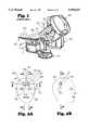
- FIG. 1is a perspective view of a conventional linear accelerator, including a rotatable couch, collimator and gantry;
- FIG. 2Bis a partial cost-sectional front view of a patient's head, or skull, having a tumor disposed therein, taken along line 2A--2A of FIG. 2B;
- FIG. 2Bis a partial cross-sectional side view of the same patient's head taken along line 2B--2B of FIG. 2A;
- FIG. 2Cis a schematic diagram indicating a path of travel of the gantry of the linear accelerator of FIG. 1;
- FIGS. 2D-2Fare front views of conventional radiation compensator blocks used with the linear accelerator of FIG. 1;
- FIG. 2Gis the same view as FIG. 2B, illustrating the spatial contour of the tumor as seen by a radiation beam as it passes through the compensator block of FIG. 2D, or the "beam's eye view" of the tumor;
- FIG. 2His a partial cross-sectional view of the patient's head taken along line 2H--2H of FIG. 2A, and illustrates the spatial contour of the tumor as seen by a radiation beam as it passes through the compensator block of FIG. 2E;
- FIG. 2Iis a partial cross-sectional view of the patient's head taken along line 2I--2I of FIG. 2A, and illustrates the spatial contour of the tumor as seen by a radiation beam as it passes through the compensator block of FIG. 2F;
- FIG. 3Ais a partial cross-sectional front view of a patient's head having a tumor disposed therein, taken along line 3A--3A of FIG. 3B;
- FIG. 3Bis a partial cross-sectional side view of a patient's head taken along line 3B--3B of FIG. 3A;
- FIG. 3Cis a schematic diagram illustrating the rotation of the gantry of the linear accelerator of FIG. 1;
- FIG. 3Dis a partial cross-sectional side view of a patient's head of FIG. 3B illustrating a method of conformal radiation therapy
- FIG. 3Eis a partial cross-sectional top view of a patient's head taken along line 3E--3E of FIG. 3A illustrating a conformal radiation therapy method
- FIG. 3Fis a partial cross-sectional side view of the patient's head taken along line 3F--3F of FIG. 3A, illustrating a method of conformal radiation therapy
- FIG. 4is a partial cross-sectional view of a patient's head having a tumor disposed therein, this view being similar to FIG. 3E, illustrating the path of a radiation beam through a portion of a tumor in accordance with the present invention
- FIG. 5is a front view of the tumor of FIG. 4 taken along line 5--5 of FIG. 4, and illustrating the spatial contour of the tumor as seen by a radiation beam in accordance with the present invention
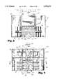
- FIG. 6is a partial cross-sectional view of an apparatus for use in conformal radiation therapy, taken along line 6--6 of FIG. 7;
- FIG. 7is a partial cross-sectional side view of the apparatus of FIG. 6 taken along line 7--7 of FIG. 6;
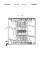
- FIG. 8is a partial cross-sectional view of the apparatus of FIG. 6 taken along line 8--8 of FIG. 7;
- FIG. 9is a partial cross-sectional view of the apparatus of FIG. 6, and is similar to FIG. 8, illustrating the operation of a means for independently modulating the beam intensity of a plurality of radiation beam segments;
- FIG. 10is a flow diagram of a radiation planning system for controlling the operation of the apparatus of the present invention.
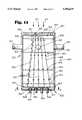
- FIG. 11is a partial cross-sectional view of an apparatus for use in conformal radiation therapy, in accordance with the present invention.
- FIG. 12is a partial cross-sectional view of the apparatus of FIG. 11, taken along line 12--12 of FIG. 11;
- FIG. 13is a side view of an expandable, radiolucent member in accordance with the present invention.
- FIG. 14is a cross-sectional view taken along line 14--14 of FIG. 13;
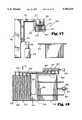
- FIG. 15is a side view of a conventional linear accelerator, provided with the apparatus of the present invention.
- FIG. 16is a partial cross-sectional, schematic view of the apparatus of FIGS. 11 and 12, wherein some of the expandable, radiolucent members are fully expanded, and some are unexpanded;
- FIG. 17is a side view of the apparatus of FIG. 15, wherein all of the expandable, radiolucent members of the apparatus in accordance with the present invention, are unexpanded;
- FIG. 18is a partial cross-sectional schematic view of the apparatus of FIGS. 11 and 12, in accordance with the present invention, wherein all of the expandable, radiolucent members are unexpanded.
- a conventional linear accelerator 300is shown as including a gantry 301, turntable 302 which causes patient couch 303 to rotate therewith, and a conventional collimator 304.
- the three axes of rotation of the gantry 301, turntable and couch 302, 303, and collimator 304are designated with the letters G, T, and C, respectively.
- the patient 305is disposed upon the rotatable couch 303 by use of a conventional stereotactic fixation device (not shown), or other conventional means for fixating the body to the patient couch 303.
- a conventional stereotactic fixation devicenot shown
- One type of fixation systemthat could be utilized is that disclosed in U.S. patent application Ser. No. 07/515,429, filed Apr. 27, 1990, now U.S. Pat.
- the isocenter 307is defined as the point of intersection of the three axes of rotation, C, G, and T of linear accelerator 300.
- the use of the term "tumor” hereinencompasses any target, lesion, or tumor which is to be the subject of the conformal radiation therapy of the present invention.
- the tumor 306 described as being treated hereinis disposed within the patient's skull 308, the method and apparatus of the present invention may be used to treat tumors located in any anatomical location in the patient's body.
- the linear accelerator 300produces a beam of radiation 311 (FIG. 4), made up of photons which generate gamma rays when they impinge upon human tissue, and the radiation beam 311 is focused and directed toward tumor 306.
- the radiation beam 311exits from the conventional accelerator head 312, and then may pass through a conventional collimator 304, as it travels toward the tumor 306.
- the method and apparatus of the present inventionmay be also utilized with a conventional cobalt therapy device, or any other radiation device which produces a radiation beam 311 having a pre-determined, constant beam intensity, such as linear accelerator 300 or a cobalt therapy device (not shown).
- skull 308has a tumor 306 disposed therein, tumor 306 having a total tumor volume which is encased by the outer surfaces 313 of tumor 306.
- Tumor 306has concave surfaces 314 when viewed from the front as shown in FIG. 2A.
- Tumor 306may also be referred to as "re-entrant in shape” because it "reenters” itself or has concave surfaces 314.
- tumor 306 when viewed from the side of the patient's skull 308has a generally oval-shaped configuration.
- a plurality of compensator blocks 315, 316are formed and disposed between collimator 304 and the tumor 306, so as to conform the shape of the radiation beam 311 which passes through openings 317, 318 in compensator blocks 315, 316 to match the spatial contour of the tumor as seen by the radiation beam as it passes through the tumor, as the collimator 304 of linear accelerator 300 is rotated about the patient.
- the spatial contour of the tumor as seen by a radiation beam as it passes through the targetis also generally referred to as the "beam's eye view", or what the shape of the tumor is when viewed along the longitudinal axis 320 of radiation beam 311 (FIG.
- Compensator blocks 315, 316are typically formed of a radiation shielding material, whereby the radiation beam is blocked from passing through such material, and may only pass through openings 317, 318 formed in compensator blocks 315, 316.
- a conventional multileaf collimatormay be used to provide openings which substantially correspond in shape with openings 317, 318.
- tumor 306is provided with radiation therapy utilizing compensator blocks 315, 316, while rotating gantry 301 in an ear-to-ear rotation as shown in FIG. 2C.
- Couch and turntable 303, 302may be rotated 90 degrees from its position shown in FIG. 1, so that its longitudinal axis lies parallel with axis G of the gantry 301.
- Three radiation beams 322-324may be directed toward tumor 306, beams 322, 324 toward the ears of the patient and beam 324 downwardly through the front of the patient's skull 308.
- radiation beam 322passes through opening 317 of compensator block 315 and travels toward tumor 306.
- the spatial contour 325 of tumor 306, as seen by radiation beam 322 as it passes through tumor 306,is shown in FIG. 2G.
- linear accelerator 300Upon rotation of gantry 301 through an arc of 90 degrees, linear accelerator 300 then generates radiation beam 323, which after passing through opening 318 in compensator block 316 travels through the front of the skull 308 and strikes target 306.
- the spatial contour 326 of the tumor 306, as seen by the radiation beam 323 as it passes through the tumor 306, or the beam's eye view of tumor 306,is illustrated in FIG. 2H.
- radiation beam 324passes through opening 317 in compensator block 315 of FIG. 2F and enters skull 308 and strikes target 306.
- the spatial contour 327 of the tumor 306 as seen by radiation beam 324is shown in FIG. 2I.
- the radiation exposure to tumor 306 by radiation beam 323corresponds to the actual spatial configuration of tumor 306 as illustrated in FIG. 2A.
- the resultant radiation exposure obtained from radiation beams 322, 324would not correspond to the actual spatial configuration of the tumor 306 because tumor 306 is re-entrant or concave in a plane parallel to that of radiation beams 322, 324.
- the intensity of radiation beams 322, 324are not varied to accommodate for the differing thickness of tumor 306 when the thickness is measured along the longitudinal axis 331 (FIG. 2A) of tumor 306.
- the tumor 306has two enlarged end portions 328, 329 (FIG. 2A) and a smaller diameter central portion 330.
- portions of radiation beams 322, 324will pass through differing thicknesses of tumor 306 along its longitudinal axis 331, because of concave surfaces 314, which result in the enlarged end portions 328, 329.
- the intensity of radiation beams 322, 324typically remains constant, or in some instances might by varied across the entire spatial contour of the tumor as seen by the radiation beam, different portions of tumor 306 would receive an incorrect or insufficient dose of radiation.
- the same tumor 306 in patient's skull 308will be treated with the linear accelerator 300 of FIG. 1.
- the radiation beam 311 from accelerator head, or radiation beam source, 312, of linear accelerator 300has a pre-determined, constant beam intensity, which will be used for treatment of a volume of tissue 400 (FIGS. 3D and FIG. 5), which volume of tissue 400 has at least a part 401, or first discrete portion 407, of tumor 306 disposed therein.
- the relative rotational motion between the patient's skull 308 and accelerator 312may be provided in the same manner as previously described in connection with FIGS. 2A-2I.
- the method of conformal radiation therapy in accordance with the present inventiongenerally includes the steps of: directing the radiation beam 311 from a first position 405, as in the direction of arrow 406 (FIGS. 3A and 3C) toward a first discrete portion 407 of the tumor 306, which discrete portion 407 has a tumor volume less than the total tumor volume of the tumor 306; and spatially modulating the beam intensity of the radiation beam 311 over the first discrete portion 407 of the tumor 306, whereby the first discrete portion 407 of the tumor 306 receives a dose of radiation to treat the first discrete portion 407 of the tumor 306, while minimizing the irradiation of healthy tissue 335, which may be disposed adjacent to the tumor 306 and within volume of tissue 400.
- the first discrete portion 407 of tumor 306is disposed in a slice-shaped portion 411 of tissue volume 400.
- the use of the term "slice-shaped"is used as generally describing a thin flat piece of tissue.
- the total volume 450 of tissue of the patient containing the tumor 306is divided, or separated, into a plurality of slice-shaped portions of tissue volume, four slice-shaped portions 411, 412, 413, 414 being illustrated in FIG. 3D.
- the first slice-shaped portion 411 of tissue volume 450is illustrated in solid lines in FIG. 3D and FIG. 5, with slice-shaped portions 412-414 being illustrated in dotted lines in FIG. 3D.
- Each of the slice-shaped portions 411-414 of the total tissue volume 450have a rectangular-shaped cross-sectional configuration in a plane disposed perpendicular to the longitudinal axis 320 of the radiation beam 311 in the direction of arrow 406, and the longitudinal axis 420 of slice-shaped portion 411 of tissue volume 400 is coplanar with the longitudinal axis of the radiation beam.
- longitudinal axis 420 of slice-shaped portion 411is disposed perpendicular to the plane upon which these figures appear, and is thus designated as a point 420.
- Each of the slice-shaped portions 411-414 of the total tissue volume 450are in an abutting relationship with their adjacent slice-shaped portions, and each slice-shaped portion 411-414 lie in planes which are parallel with each other and are coplanar with the longitudinal axis 320 of the radiation beam 311, in the direction of arrow 406.
- the radiation beam 311may be directed from a second position 425 which is radially spaced from the first position 405. Radiation beam 311 is thus directed in the direction of arrow 426 (FIGS. 3A and 3C) toward the first discrete portion 407 of the tumor 306, which is disposed within another slice-shaped first portion 411' of the total tissue volume 450'.
- Slice-shaped portion 411'also has a rectangular-shaped cross-sectional configuration when viewed along the longitudinal axis 320 of radiation beam 311 when it is directed in the direction of arrow 426, as illustrated in FIGS. 3A and 3E.
- additional slice-shaped portions 412'-414'are seen to lie in abutting relationship against their adjacent slice-shaped portions 411'-414', and these slice-shaped portions of the total tissue volume 450' lie in planes which are parallel with each other.
- the beam intensity of the radiation beamis again spatially modulated over the discrete portion 407 of the tumor 306, whereby the first discrete portion 407 of the tumor receives another dose of radiation to treat the first discrete portion 407 of the tumor 306, while minimizing the irradiation of healthy tissue adjacent the tumor.
- slice-shaped portion 411" of the total tissue volume 450"also has a rectangular cross-sectional configuration lying in a plane which is perpendicular to the longitudinal axis of the radiation beam, or in the direction of arrow 431. Additionally, slice-shaped portions 412"-414" of total tissue volume 450", as previously described, are also in abutting relationship with adjacent slice-shaped portion of total tissue volume 450" with each of the slice-shaped portions 411"-414" lying in parallel planes.
- each of these slice-shaped portions 411"-414"are coplanar with the longitudinal axis of the radiation beam 311 acting upon it in the direction of arrow 431.
- radiation beam 311is directed in the direction of arrow 431 toward slice-shaped portions 411"-414" of total tissue volume 450"
- its beam intensityis spatially modulated over the first discrete portion 407 of tumor 306 disposed within slice-shaped portion 411" of tissue volume 400.
- slice-shaped portions 411, 411", 411" of total tissue volumes 450, 450", 450"are coplanar with each other, as is the case for slice-shaped portions: 412, 412', 412"; 413, 413', 413"; and 414, 414', 414".
- the other discrete portions 408-410 of tumor 306 disposed within their respective slice-shaped portions 412, 412', 412"; 413, 413', 413"; 414, 414', 414",may be treated in turn in the manner previously described, whereby from each radially spaced location from which radiation beam 311 is directed toward tumor 306, the beam intensity of radiation beam 311 is spatially modulated over the discrete portion of tumor 306 being treated.
- the subsequent treatment of additional slice-shaped portions 412-414, 412'-414', 412"-414"may be accomplished by moving the patient with respect to the radiation beam source 311, or the accelerator head 312, a distance equal to the thickness of the slice-shaped portions of the tissue volume being treated.
- the entire tumor 306, or its entire tumor volume, contained within the total tissue volumes 450, 450', 450"may be properly treated by the radiation therapy.
- the number of slice-shaped portions of the total tissue volume being treatedmay be varied, as well as the thickness of each slice-shaped portion of tissue volume. Four slice-shaped portions of tissue volume were shown treated in FIGS.
- 3D-3Fwhich number of slice-shaped portions of tissue volume were selected for illustrative purposes only. Furthermore, it should be noted that the application of the radiation beam from only three locations 405, 425, 430, has also been used for illustrative purposes only, as will be hereinafter described in greater detail.
- Tumor 306'has a different configuration from that of tumor 306 illustrated in the preceding figures; however, it is also re-entrant in shape, having concave surfaces 314 as seen in FIG. 4, with concave surfaces 314' as viewed in FIG. 5.
- Radiation beam 311is initially shaped into at least one radiation treatment beam 500 which has a longitudinal axis 501 which corresponds to the longitudinal axis 320 of radiation beam 311. Longitudinal axis 501 extends along the same path along which radiation beam 311 travels.
- Radiation treatment beam 500has a rectangular-shaped cross-sectional configuration 502 which is disposed in a plane perpendicular to the longitudinal axis 501 of the radiation beam 311.
- the rectangular-shaped cross-sectional configuration 502 of radiation treatment beam 500corresponds to the rectangular-shaped cross-sectional configuration of the slice-shaped portion 411 of tissue volume 400 with the longitudinal axis 501 of the radiation treatment beam 500 being coplanar with the longitudinal axis 420 of slice-shaped portion 411 of tissue volume 400.
- the rectangular cross-sectional configuration 502 of the at least one radiation treatment beam 500is separated into a plurality of radiation beam segments 510-514, in a manner which will be hereinafter described.
- the beam intensity of the plurality of radiation beam segments 510-514 of the radiation treatment beam 500are then independently modulated across the rectangular cross-sectional configuration 502 of the radiation treatment beam 500, whereby the first part 401 of the tumor 306', which has a varying thickness in a direction along the longitudinal axis 420 of the slice-shaped portion 411 of tissue volume 400, is treated by the plurality of radiation beam segments 510-514.
- Each radiation beam segment 510-514 of radiation treatment beam 500have a beam intensity in accordance with the thickness of the part 401 of tumor 306' through which each radiation beam segment 510-514 passes. For example, as seen in FIG.
- arrows 530denote the thickness T of one portion, or segment, 531 of the part 401 of tumor 306', through which radiation beam segment 510 of radiation treatment beam 500 passes.
- Arrows 532denote the thickness T' of a portion 533 of the part 401 of tumor 306' through which radiation beam segment 514 passes. Since the thickness T of tumor segment 531 is greater than the thickness T' of tumor segment 533, the beam intensity of radiation beam segment 510 must be greater than the beam intensity of radiation beam segment 514, in order to properly treat tumor segments 531, 533 with radiation treatment beam 500.
- a means for independently modulating 600 the beam intensities of the plurality of radiation beam segments 510-514is schematically illustrated to provide the spatial modulation of the beam intensity of the radiation treatment beam 500 across its rectangular cross-sectional configuration 502.
- a preferred form of independent beam modulation means 600 from that shown in FIG. 4will be hereinafter described in connection with FIGS. 6-9.
- independent modulation of the beam intensities of the plurality of radiation beam segments 510-514is illustrated by disposing differing thicknesses of a radiation attenuation material between radiation beam 311 and radiation treatment beam 500.
- the path of radiation beam 311 through beam intensity modulation means 600is open, whereby the beam intensity of radiation beam segment 510 treating tumor segment 531 is the same pre-determined, constant beam intensity of radiation beam 311.
- segment 533 of tumor 306'is relatively thin in comparison with the other segments of part 401 of tumor 306', a relatively thick portion 540 of radiation attenuation, or blocking, material 540 is disposed in the path of radiation beam 311. The beam intensity of radiation beam segment 514 is thus reduced, commensurate with the necessary dose of radiation to properly treat segment 533 of tumor 306'.
- Radiation treatment beam 500would comprise radiation beam segments 510-514, and radiation treatment beam 500' would comprise radiation treatments beam segments 510'-514'.
- Each radiation treatment beam 500, 500'would have a longitudinal axis extending along the path which the radiation treatment beams 500, 500' travel and have a rectangular-shaped cross-sectional configuration in a plane disposed perpendicular to the longitudinal axis 501 of the radiation treatment beams 500, 500'.
- radiation beam segments 510-514would extend the entire distance from the bottom to the top of the rectangular cross-sectional configuration 502 of the radiation treatment beam 500.
- this radiation treatment beam 500with its plurality of radiation beam segments 510-514 would be directed toward the first discrete portion 407 of tumor 306 in the first slice-shaped portions 411-411" of tissue volume 400 as radiation beam 311 is rotated about the patient's skull 308, as previously described in connection with FIGS. 3D-3F.
- the patientwould then be moved with respect to the radiation beam 311, a distance equal to the thickness of the slice-shaped portion 411 being treated, whereby the process would be repeated to treat the next plurality of slice-shaped portions 412-412".
- the beam intensity of the radiation beam segments 510-514would be independently modulated, dependent upon the thickness of the tumor segment through which the radiation beam segment passes, as previously described.
- radiation beam 311is rotated about an arc of approximately 160 degrees in the direction of arrow 321 (FIG. 3C), and radiation beam 311 is turned on and directed toward the tumor, and its beam intensity modulated, after each 5 degrees of rotation about the skull 308, or in 5 degree segments of the 160 degree radial arc.
- two adjacent slice-shaped portions of tissuesuch as slice-shaped portions 411-411" and 412-412" may be simultaneously treated in the manner previously described. It would then be necessary to move the patient with respect to the radiation beam 311, or radiation beam source 312, a distance equal to the thickness of two slice-shaped portions of tissue, whereby another pair of adjacent slice-shaped portions of tissue may be treated, such as slice-shaped portions 413-413" and 414,414".
- control of the means for independently modulating 600 the beam intensity of the plurality of radiation beam segments 510-514 or the spatial modulation of the beam intensity of the radiation beam 311 across each of the plurality of slice-shaped portions of the tissue volumeis preferably controlled by a suitable computer system.
- an apparatus 700 for use in conformal radiation therapy of a tumor with a radiation beam 311 from a radiation beam source, or linear accelerator 300, the radiation beam 311 having a pre-determined, constant beam intensityin accordance with the present invention generally includes: a means for shaping 701 the radiation beam 311 into at least one radiation treatment beam 500 (FIG. 4); a means for separating 702 the at least one radiation treatment beam 500 into a plurality of radiation beam segments 510-514 (FIG. 4); and a means for independently modulating 600 the beam intensity of the plurality of radiation beam segments 510-514.
- Apparatus 700is preferably mounted in a housing 705 which permits apparatus 700 to be attached to a conventional wedge tray slot (not shown) on a conventional linear accelerator 300 or cobalt therapy treatment unit (not shown).
- shaping means 701preferably includes two blocks 710, 711 of radiation shielding material, such as tungsten, which define a rectangular-shaped opening 713 through which a part of the radiation beam 311 passes.
- the rectangular-shaped opening 713has a length dimension L (FIG. 6) and a width dimension W (FIG. 7).
- blocks 710, 711are movable with respect to each other, whereby the width dimension W of the rectangular-shaped opening 713 is variable. As seen in FIG.
- stepper motors 714may be associated with blocks 710, 711 as by any suitable attachment member 715, whereby the width dimension W of rectangular-shaped opening 713 may be varied.
- the width dimension W of opening 713corresponds to the thickness of the rectangular cross-sectional configuration 502 (FIG. 5) of radiation treatment beam 500, which width dimension W also corresponds to the width of the slice-shaped portion 411 of tissue volume 400 as shown in FIG. 5.
- the thickness of the slice-shaped portions, or the width dimension Wis selected within a range of 5 mm. to 2 cm.
- the length dimension L of blocks 710, 711, which corresponds to the length of each slice-shaped portionis 20 cms.
- the means for separating 702 the rectangular-shaped cross-sectional configuration of the at least one radiation treatment beam into a plurality of radiation beam segmentspreferably includes a plurality of independently movable metal members, or metal vanes, 720.
- the number of metal members 720corresponds to the desired number of radiation beam segments to be formed.
- twenty metal members 720are provided, a first group, or set 721 of ten metal members 720 being disposed in a row 723, and a second set 722 of metal members 720 being disposed in a row 724.
- the first four metal members 720 of the first set 721 of metal members 720 in row 723may be considered as corresponding to, and forming, the four radiation beam segments 510-514 of FIG.
- metal members 720 of the second set 722 of metal members 720 in row 724would form the radiation beam segments 510'-514' of FIG. 5.
- the plane 726 formed by the abutting surfaces between the metal members 720 of the first and second rows 723, 724 of metal members 720would correspond to the horizontal dotted line 550 in FIG. 5, and blocks 710, 711 would be utilized to form two radiation treatment beams 500, 500', wherein the width dimension W of opening 713 would correspond to the thickness of two slice-shaped portions, such as slice-shaped portions 410, 411 (FIG. 3D).
- metal members 720are normally in a first closed position 730 wherein the metal members 720 are in a closely fitting abutting relationship.
- each metal member 720is movable from the first closed position 730 to a second open position 731 (FIG. 9).
- a radiation beam segmentsuch as radiation beam segment 510 of FIG. 4 may pass through the opening 732 toward a portion of a tumor.
- the metal membersblock the path of the radiation beam associated with that metal member 720, and thus do not permit the radiation beam segment associated with that closed metal member 720 to pass toward a tumor.
- two slice-shaped portions of tissue volumehaving a length of 20 cms. and a thickness varying between one-half to two cm. may be treated with one rotational path of radiation beam 311. Twenty individually modulated radiation beam segments are thus provided by metal members 720.
- Each metal member 720is provided with a means for independently moving 740 each metal member 720 from the first closed position 730 to the second open position 731.
- the means for independently moving 740 each metal member 720is an actuator 741, an actuator 741 being associated with each metal member 720.
- each actuator 741is air powered and has a solenoid valve 742 associated with each actuator 741.
- Each solenoid valve 742controls the operation of its associated actuator 741 and in turn its associated metal member 720, in response to control signals to be provided, as hereinafter described.
- Each of the metal members 720may be connected to its respective actuator 741 as by a conventional piston 743 associated with each actuator 741.
- Suitable air lines 744extend from the solenoid valves 742 to the actuators 741.
- a conventional compressed air supply(not shown) is provided in the therapy treatment room and air is in turn supplied to the solenoid valves 742 in a conventional manner.
- Each actuator 741is preferably of an air-retract, spring-extend type, whereby a spring (not shown) associated with each actuator 741 normally urges its associated metal members 720 into the first closed position 730. Accordingly, should electrical power to apparatus 700 fail, which electric power is necessary to provide the control signals to operate valves 742, or should air pressure to actuators 741 cease, each metal member will spring back into its first closed position, thus blocking its respective radiation beam segment.
- a solenoid valve(not shown) is also associated with each block 710, 711, which solenoid normally maintains blocks 710, 711 in an open position. Should electric power to apparatus 700 fail, or should an error signal be generated by the system controlling the operation of metal members 720, the solenoid will immediately close blocks 710, 711 into their closed configuration illustrated in FIG. 7, whereby no radiation may pass to the patient.
- each metal member 720has a substantially identical shape, a substantially uniform cross-sectional configuration, and a substantially uniform depth dimension D (FIG. 7) in the direction of the path of the radiation treatment beam 500.
- metal members, or vanes, 720are made of tungsten, or any other suitable metallic material having the necessary radiation blocking characteristics.
- the longitudinal axes of the metal members 720also diverge slightly outwardly from the center most metal member to account for the divergence of radiation treatment beam 500.
- the beam intensity of the plurality of radiation beam segmentsis performed by the solenoid valves and actuators 742, 741 and metal members 720.
- the beam intensity of each radiation beam segment associated with each metal member 720is modulated by independently varying the amount of time each metal member 720 is disposed in the first closed position 730, whereby the longer the period of time during which a metal member 720 is in the first closed position, causes a lowering of the beam intensity of its corresponding radiation beam segment.
- the beam intensity of a radiation beam segmentmay be varied from a value of 0 to 1.
- a beam intensity of 0would correspond with a metal member 720 remaining in its first closed position 730 for the entire period of time during which radiation beam 311 is on and passes through rectangular-shaped opening 713 toward metal members 720. If a metal member 720 associated with a radiation beam segment remains in its second open position 731 the entire period of time while radiation beams 311 is on, the beam intensity of that radiation beam segment would be 1.
- a control system for apparatus 700which includes electronics 760 disposed within housing 705, determines how long a given metal member 720 remains in its first closed position 730 during the radiation treatment therapy, as will be hereinafter described in greater detail. It should be noted that by varying the time a metal member 720 remains in its first closed position 730 can be correlated to the schematic representation of varying thicknesses of radiation absorbing material 540 illustrated and previously described in connection with FIG. 4.
- apparatus 700 or the method of conformal radiation therapy of the present inventionIn order for apparatus 700 or the method of conformal radiation therapy of the present invention to efficiently operate it is necessary that appropriate control signals be provided to the electronics 760 of apparatus 700 to control the operation of apparatus 700, including the means for independently modulating 600 the beam intensity of the radiation beam segments of the radiation treatment beam used in apparatus 700. For example, dependent upon the location, size, and dimensions of a particular tumor within a patient's body, it is necessary to determine the dose of radiation to be directed toward the tumor portions disposed within the various slice-shaped portions of tissue volume being treated, with respect to the radial position of the radiation beam source used to treat the particular slice-shaped portions of tissue.
- Conventional radiation planning systemare available which can provide the necessary control information utilized to control apparatus 700 and permit the method of conformal radiation therapy of the present invention to be performed. With reference to FIG. 10, a preferred radiation planning system to obtain the information that is utilized by apparatus 700 and in practicing the method of the present invention will be described.
- the first step of the processis generally referred to as the Registration Process step 800.
- Thisis the process step of aligning a set of conventional axial slice images of the portion of the patient to be treated by the conformal radiation therapy of the present invention. These images are first obtained by conventional computerized tomographic ("CT") scanning or magnetic resonance imaging (“MRI”) techniques which produce an image representing a "slice” of tissue displayed with anatomical accuracy.
- CTcomputerized tomographic
- MRImagnetic resonance imaging
- the series of "slices”which constitute the complete CT or MRI study, represents a three-dimensional picture of a particular portion of the patient, to allow visualization as a valid three-dimensional data set.
- the resulting datais achieved by sampling the input data, determining common marks of known geometry, and warping the data to be correctly aligned.
- Resulting resolutionis set so that it is geometrically correct based on the known patient fixation device utilized, as previously described, and if images have been scanned from film, gray scale image normalization is done based on reference graybars including in the images.
- Conventional two-dimensional image warping techniquesare utilized, with super sampling and filtering as required for resolution adjustment.
- Image slice spacingis entered by the operator of the planning system and verified by the known patient fixation device geometry.
- the next step of the systemis generally referred to as the Anatomy Tools step 801.
- the physicianidentifies the three-dimensional volume of the structure significant to radiation planning, in a conventional manner, whereby the physician identifies anatomical structures on an image slice-by-slice basis.
- the Prescription Panel step 802allows the physician to input into the planning system the desired goal of the radiation therapy treatment, in terms of the desired target dose, sensitive structure limits, delivery complexity, and aggressiveness. Aggressiveness relates to the relative importance of maximally treating the target, or tumor, as compared with sparing sensitive, adjacent anatomical structures. These parameters are utilized in the plan optimization step 803.
- the radiation plan optimizationis a specific case of an inverse problem, where the goal is to determine the best way to achieve the dose prescription.
- a Simulated Annealing techniqueis utilized to do this optimization by dividing the radiation delivery into a series of narrow slices, or slice-shaped portions, or arc treatments, and optimizing each of these arcs separately.
- the annealing cooling schedule utilizedfits into the class of FSA (Fast Simulated Annealing) techniques.
- FSAFast Simulated Annealing
- the next step in the planning systemis the Instrument Fitting step 804.
- the resulting optimized set of radiation beam positions and beam weights, or beam intensities for the radiation beam segmentsis fitted into the delivery capabilities of apparatus 700, after optimization.
- An iterative processis utilized to account for OF adjustments (Output Factor), the timing of the movement of metal members 720, and limitations of simultaneous movements to arrive at control information for apparatus 700 that represent the optimized plan and can be delivered within the operating limitations of device 700.
- OF adjustmentsOutput Factor
- a Strength Normalize step 805further normalizes the arcs of rotation through which the radiation beam source travels to insure that the tumor receives a consistent radiation dose from each position selected in order to eliminate what are known as "hot” or “cold” regions in the tissue volume being treated. This step may be done by varying the radiation dose rate of the radiation source, and may be accomplished by use of a conventional, simple linear scaling technique.
- the radiation dose to the patientis simulated based upon the control information for device 700.
- the algorithm used in this stepis based upon the Three-Dimensional Modified Path Length technique, as is known in the art. Examples of this algorithm are discussed in the following publications: "Algorithm for Dosimetry of Multiarc Linear Accelerator Stereotactic Radiosurgery", G. Luxton et al., Medical Physics, vol. 18, pp. 1211-1221 (1991); “Dosage Calculations in Radiation Therapy", W. L. Saylor, published by Urban & Schwarzenberg (1979), which publications are incorporated herein by reference.
- the Output Process step 807permits the physician to review the simulated radiation dose information and to approve the radiation plan for patient delivery. After such review and approval, a floppy disk is generated containing the data to control apparatus 700 for the specific radiation delivery case.
- the dataincludes instructions for the timing and movement of metal members 720, radiation source setup information, and conventional patient information.
- the Delivery System step 808is accomplished, wherein the method steps of the conformal radiation therapy method of the present invention are performed as previously described, in order to treat the tumor in the patient.
- the method and apparatus 700may be utilized in rotational radiation therapy plans, wherein it is preferred that no more than 10 non-coplanar arcs of approximately 210 degrees are used, although any number of arcs may be used, if desired, which arcs may vary from 0 degrees to 360 degrees.
- the positioning and location of the arcs with respect to the patient, and the number of arcs utilizedare determined in accordance with the previously described planning system.
- the beam intensities of the radiation beam segments directed toward the tumorare updated every 5 degrees of rotation, whereby an optimized dose distribution for the tumor will be produced.
- Conventional fixed port radiation treatment planscan also be practiced with apparatus 700 of the present invention.
- the portsdo not have to be coplanar, and the location of the ports can be either inputted into apparatus 700 by the physician, or optimized by the radiation planning system previously described.
- the foregoing rotational radiation treatment plan, or fixed port radiation plancan be used for tumors occurring anywhere in the body with the method and apparatus of the present invention. Since it is preferred that the length of the rectangular cross-sectional configuration of the radiation treatment beam is shaped to be 20 cm. in length, the rotational mode of operation is thus limited to treatment of cross-sectional areas of 20 or less centimeters. Fixed port plans can be utilized with tumor of any size.
- the apparatus 700may also be provided with a plurality of slot sensors which indicate the movement of the metal members 720, whereby the radiation field intensity delivered to the patient may be indirectly monitored.
- the data from the set of slot sensorsmay be multiplexed with the incoming beam strength, or the beam intensity of the radiation treatment beam, to determine if the outgoing intensities of the radiation beam segments correspond to the prescribed dose. If the desired beam intensities of the radiation beam segments do not correspond to those prescribed by the radiation planning system, a control signal can be provided to quickly close blocks 710, 711 and metal members 720 to provide protection of the patient from an incorrect radiation exposure.
- the method and apparatus 700' for conformal radiation therapy of the present inventionwill be described. While the previously described method and apparatus 700 for conformal radiation therapy, as described in connection with FIGS. 1-10 has proven to be effective in spatially and temporally modulating a linear accelerator beam in a slice-by-slice manner in order to produce intensity modulation conformal radiation therapy, a minor disadvantage of that method and apparatus results from the fact that only two slices of tissue volume may be treated with one rotation of the gantry of the linear accelerator. Although the slices may be of arbitrary thickness, greater resolution is accomplished by selecting slices for treatment that are as thin as possible. As the thickness of the treatment slices decreases, the time it takes to treat the patient increases because more treatment slices are required in order to treat the entire tumor volume.
- the method and apparatus 700' of the present inventiontreats an unlimited number of slices of the volume of tissue containing a tumor, and in many instances, dependent upon the size of the tumor, is able to treat the entire volume of tissue containing the tumor, with only one rotation of the gantry of the linear accelerator, thus decreasing the time necessary to treat the patient.
- the same reference numeralsare used for elements previously described, and primed reference numerals are utilized for elements having functions and structures similar to those previously described.
- a conventional linear accelerator 300is shown as including a gantry 301, a patient support table, or patient couch, 303, accelerator head, or beam source, 312, which may include a conventional collimator 304, and a radiation beam 311, having a predetermined, constant beam intensity.
- the apparatus 700' for use in conformal radiation therapyis mounted to, and beneath, accelerator head 312, and includes: a means for separating 702' the radiation treatment beam 500 into a plurality of radiation beam segments 510'-514'; and a means for independently modulating 600' the beam intensity of the plurality of radiation beam segments 510'-514' to spatially modulate the beam intensity of the radiation treatment beam 500' across the tumor to be treated.
- Apparatus 700'includes a control system 760', as will be hereinafter described in greater detail.
- the means for separating 702' the radiation treatment beam 500' into a plurality of radiation beam segments 510'-514'preferably includes a housing 705', adapted to be secured to the bottom of the accelerator head 312, as shown in FIG. 15.
- Housing 705'contains a plurality of compartments 820, extending from the top 821 to the bottom 822 of housing 705', sixteen compartments 820 being used for illustration purposes, as shown in FIG. 12.
- a greater or fewer number of compartments 820may be provided within housing 705'.
- Compartments 820located within housing 705', are generally defined by a plurality of divider members 823 disposed in housing 705'.
- divider members 823are a plurality of thin dividing rods 824 of any suitable number formed of a stiff radiation non-blocking, or radiolucent, material, such as any suitable radiolucent plastic material, and may be disposed in a staggered relationship as shown in connection with the far left-hand compartment 820.
- the means for independently modulating 600' the beam intensity of the plurality of radiation beam segments 510'-514'preferably includes a plurality of expandable, radiolucent members 825, and an expandable, radiolucent member 825 is associated with each compartment 820.
- a quantity of flowable, radiation blocking material 826(FIGS. 16 and 18) is disposed within housing 705' and within each compartment 820 when the expandable members 825 are unexpanded, as shown in FIGS. 17 and 18.
- a reservoir 830 for the flowable, radiation blocking material 826is associated with housing 705', as by providing housing 705' with outlet tubes 831 in fluid communication with the interior 832 of housing 705' and reservoir 830 (FIGS. 16 and 18).
- the expandable members 825Upon expansion of the expandable members 825, the expandable members 825 displace the flowable, radiation blocking material 826 outwardly from the compartment 820 associated with the expandable member 825 and into the reservoir 830 so that a radiation beam segment 510'-514' may pass through the compartments 820 associated with each expanded radiolucent member 825 toward a portion of the tumor 306' (FIG. 4) to be treated.
- each expandable, radiolucent member 825is preferably an inflatable balloon 835 formed of a thin radiolucent material, such as latex rubber.
- the thickness of the walls 836 forming inflatable balloons 835is approximately 0.004-0.006 inches, whereby the inflatable balloons 835 are very flexible.
- the walls 836 of inflatable balloons 835move inwardly toward each other and form what may be considered a non-linear single wall surface 836', having an undulating configuration, as seen in FIGS. 16 and 18.
- four inflatable balloons 835are illustrated in their expanded, inflated configuration within their associated compartments 820 within housing 705'.
- FIG. 11four inflatable balloons 835 are illustrated in their expanded, inflated configuration within their associated compartments 820 within housing 705'.
- five inflatable balloons 835are schematically shown in their expanded, inflated configuration within their respective compartments 820 within housing 705'.
- another five expandable, radiolucent members 825, or inflatable balloons 835are illustrated in their unexpanded, or deflated configuration previously described.
- each inflatable balloon 835has a substantially square cross-sectional configuration along the longitudinal axis 837 of each balloon 835. In its expanded, inflated configuration, its cross-sectional configuration increases in size from its top 838 to its bottom 839.
- the bottom portion 839 of each balloon 835may include a small diameter tubular member 840 adapted to be disposed in fluid communication with a source of pressurized fluid, as will be hereinafter described, in order to selectively inflate, or deflate, each inflatable balloon 835.
- each compartment 820 disposed within housing 705' defined by the plurality of divider members 823has a substantially square cross-sectional configuration, and the size of the cross-sectional configuration of each compartment 820 diverges, or increases in size, from the top 821 to the bottom 822 of housing 705'.
- the expandable member 825, or balloon 835, associated with each compartmentis in its expanded, or inflated, configuration, the cross-sectional configuration of each balloon 835 substantially conforms and mates with the cross-sectional configuration of each compartment 820.
- the radiation beam 311 entering the housing 705', and originating with the accelerator head 312FIG.
- each compartment 820diverges outwardly as it passes from accelerator head, or beam source, 312, downwardly through housing 705' toward the patient.
- the degree of the divergence of each compartment 820is proportional to the divergence of the radiation beam 311 as it travels from accelerator 312, through housing 705' toward the patient on the patient support table 303 (FIG. 15).
- the divergence of the radiation beam 311is known, whereby the degree of compartment divergence for apparatus 700' can be readily determined.
- the upper and lower walls 841, 842 of housing 705'are formed of a non-radiation blocking, or radiolucent, material, to permit radiation beam 311 to pass through housing 705'.
- the lower wall 842 of housing 705'may be provided with a grid of holes, or openings, 843 through which balloons 835 may be disposed within housing 705'.
- the top 838 of each balloonmay be disposed in a spaced relationship from the upper wall 841 of housing 705', as shown in FIG. 11, or alternatively, the top 838 of each balloon 835 may be anchored, or secured, to the underside 845 of the top wall 841 of housing 705', in any suitable manner such as by glue, a small latex tie, or by wedging the top 838 of each balloon into a small opening formed in the top wall surface 841 of housing 705'.
- the top 838 of balloon 835may be formed with an elongated tubular extension, or tip, 838' in which a small plastic ball 838" is placed, the tubular extension 838' and ball 838" being wedged in the top wall surface 841 of housing 705' as illustrated in connection with the far left hand balloon 835 of FIG. 11.
- the tubes 840 disposed at the lower end 839 of each balloon 835pass through an opening 843, in the grid of holes, or openings, 843 in the lower wall 842 of housing 705'.
- the latex tubes 840may be rolled upwardly toward the lower wall member 842, as shown at 846, to seal each balloon 835 with respect to the lower wall 842.
- a seal plate 847may be secured to the lower wall 842 of housing 705 in an abutting relationship with the rolled ends 846 of tubes 840; the seal plate 847 also being made of a suitable radiolucent material.
- Seal plate 847also has a grid of openings, or holes, 848 corresponding to the location of the rolled tube ends 846, and a suitable tubular fitting 849 is threadedly received within each hole 848 and is sealed within the rolled end 846 of each tube 840 of each balloon 835.
- each fitting 849is connected to an air hose 850, and each air hose 850 is connected to a means for selectively inflating, or deflating, 851 each balloon 835.
- the means for selectively inflating, or deflating, 851 each balloon 835is a solenoid valve 852, and a solenoid valve 852 is associated with each air line 850 associated with each balloon 835.
- a source of pressurized air 853provide a pressurized fluid, or pressurized air, to the various solenoid valves 852.
- the upper wall 841 of housing 705'may be provided with tapped mounting holes 854 for securing housing 705' to accelerator head 312, via conventional bolts, or screws (not shown).
- control system 760'has an electric power line 860 extending to the housing 705' to provide electric power for the means for selectively inflating, or deflating, 851 balloons 835, or solenoids 852, as well as an air line 861 to provide the pressurized fluid, or air, to solenoid valves 852.
- Another air line 862extends from control system 760' to reservoir 830, via a pressure control means 863, or solenoid valve 864, in order to apply a predetermined pressure force upon the radiation blocking material 826 disposed within reservoir 830, as will be hereinafter described.
- reservoir 830may have the form of a piston 865 and cylinder 866 configuration, with pressure control means 863, or solenoid valve 864, supplying a predetermined fluid pressure force upon piston 865.
- the pressure force on piston 865is set to a preselected value corresponding to the total weight of the radiation blocking material 826 which is disposed in housing 705', reservoir 830, and connecting tubes 831.
- the predetermined pressure supplied to the means for selectively inflating, or deflating, 851 the balloons 835is supplied at a higher fluid pressure than the pressure force applied to piston 865. Accordingly, when a preselected balloon 835 is inflated, as shown in FIG.
- FIGS. 15 and 16illustrate preselected balloons 835 having been inflated, and radiation treatment beam 500, comprised of a plurality of radiation beam segments 510'-514' are able to pass through housing 705' to treat the tumor of the patient.
- the beam intensity of the radiation beam segments passing throughmay be spatially modulated.
- the means for selectively inflating, or deflating, 851, or solenoid valves 852any arbitrary spatial pattern for modulating the intensities of the individual radiation beam segments may be accomplished.
- the beam intensity of each radiation beam segmentis modulated to have a beam intensity related to the thickness of the portion of the tumor through which the radiation beam passes, as well as is related to other factors including: the desired dose of radiation to be delivered by the beam segment; the presence, or absence, of sensitive structures, such as healthy tissue or body organs, adjacent the path of each radiation beam segment; and the interaction of other beam segments, and their beam intensities, as they pass through the tumor and healthy tissue and body organs along other beam paths from other directions, in the case of rotational radiation therapy treatments.
- the expandable members, 825, or balloons 835are formed of a radiolucent material, such as latex rubber
- a deflated balloon 826as shown at 836' in FIGS. 16 and 18
- the presence of a deflated balloon 826, as shown at 836' in FIGS. 16 and 18has little effect on the radiation blocking capacity of apparatus 700' in the region of the collapsed, or deflated, balloon 835, because of the fact that the balloons 835, when deflated, deform in a non-linear fashion, and have the undulating configurations illustrated in FIGS. 16 and 18.
- Temporal modulation of the beam intensities of each radiation beam segment 510'-514' of radiation treatment beam 500may be accomplished by varying the amount of time each compartment 820 is selectively filled with the flowable, radiation blocking material 826.
- the beam intensity of each radiation beam segmentmay be modulated, or attenuated, by completely filling a preselected compartment 820 with radiation blocking material 826, as by completely deflating a preselected balloon 835.
- the size of the treatment field for radiation treatment beam 500is determined by the size and number of compartments 820 provided in housing 705', whereby the greater number of compartments 820 provided, results in a larger treatment field.
- the treatment fieldwill be of a sufficient size to emcompass a volume of tissue 400 (FIGS. 3D and FIG. 5), which volume of tissue 400 contains the entire tumor 306' to be treated.
- tissue 400contains the entire tumor 306' to be treated.
- only one rotation of the gantry 301 of linear accelerator 300will be necessary to provide the desired treatment to tumor 306' for a given orientation of the patient with respect to the apparatus 700', before the orientation of the tumor 306' with respect to accelerator head 312 is changed, as by rotating patient support table 303, as previously described in connection with FIG. 1.
- a static radiation treatment fieldcan be created by maintaining a preselected number of compartments 820 filled with radiation blocking material 826, while the remaining preselected compartments are devoid of radiation blocking material 826, as illustrated in FIG. 16.
- Such a static radiation treatment fieldhas distinct advantages over conventional multileaf collimator static radiation treatment fields, because "islands" of radiation blocking material, such as island 870 in FIG. 16 formed by radiation beam segments 511' and 512' can be disposed within the radiation treatment field. Such "islands” are not possible with conventional multileaf collimators, since they only "shape” or conform the outer edges of a radiation treatment beam.
- Rotational radiation therapy treatmentsmay be provided with apparatus 700', whereby as the accelerator gantry 301 rotates about the patient, control system 760' controls the operation of the means for selectively inflating, or deflating, 851 balloons 835. Control system 760' provides the necessary and appropriate control signals to apparatus 700' in the manner previously described in connection with FIG. 10.
- the compartmentscould be formed as permanent, rigid structures within the housing, and the compartments are selectively filled or emptied of the flowable, radiation blocking material by pumping the flowable, radiation blocking material into, or out of, preselected compartments. Accordingly, the invention is therefore to be limited only by the scope of the appended claims.
Landscapes
- Health & Medical Sciences (AREA)
- Engineering & Computer Science (AREA)
- Biomedical Technology (AREA)
- Physics & Mathematics (AREA)
- General Health & Medical Sciences (AREA)
- Radiology & Medical Imaging (AREA)
- Life Sciences & Earth Sciences (AREA)
- Animal Behavior & Ethology (AREA)
- Nuclear Medicine, Radiotherapy & Molecular Imaging (AREA)
- Public Health (AREA)
- Veterinary Medicine (AREA)
- Pathology (AREA)
- Spectroscopy & Molecular Physics (AREA)
- General Engineering & Computer Science (AREA)
- High Energy & Nuclear Physics (AREA)
- Radiation-Therapy Devices (AREA)
Abstract
Description
Claims (37)
Priority Applications (6)
| Application Number | Priority Date | Filing Date | Title |
|---|---|---|---|
| US08/245,626US5596619A (en) | 1992-08-21 | 1994-05-17 | Method and apparatus for conformal radiation therapy |
| JP7141166AJPH0847545A (en) | 1994-05-17 | 1995-05-16 | Method and apparatus for conformal radiotherapy |
| KR1019950012027AKR950031129A (en) | 1994-05-17 | 1995-05-16 | Method and apparatus for conventional radiation therapy |
| DE69533325TDE69533325T2 (en) | 1994-05-17 | 1995-05-17 | Device for conformal radiotherapy |
| EP95303286AEP0695560B1 (en) | 1994-05-17 | 1995-05-17 | Apparatus for conformal radiation therapy |
| US08/634,785US5802136A (en) | 1994-05-17 | 1996-04-19 | Method and apparatus for conformal radiation therapy |
Applications Claiming Priority (2)
| Application Number | Priority Date | Filing Date | Title |
|---|---|---|---|
| US93340992A | 1992-08-21 | 1992-08-21 | |
| US08/245,626US5596619A (en) | 1992-08-21 | 1994-05-17 | Method and apparatus for conformal radiation therapy |
Related Parent Applications (1)
| Application Number | Title | Priority Date | Filing Date |
|---|---|---|---|
| US93340992AContinuation-In-Part | 1992-08-21 | 1992-08-21 |
Related Child Applications (1)
| Application Number | Title | Priority Date | Filing Date |
|---|---|---|---|
| US08/634,785Continuation-In-PartUS5802136A (en) | 1994-05-17 | 1996-04-19 | Method and apparatus for conformal radiation therapy |
Publications (1)
| Publication Number | Publication Date |
|---|---|
| US5596619Atrue US5596619A (en) | 1997-01-21 |
Family
ID=22927445
Family Applications (2)
| Application Number | Title | Priority Date | Filing Date |
|---|---|---|---|
| US08/245,626Expired - LifetimeUS5596619A (en) | 1992-08-21 | 1994-05-17 | Method and apparatus for conformal radiation therapy |
| US08/634,785Expired - Fee RelatedUS5802136A (en) | 1994-05-17 | 1996-04-19 | Method and apparatus for conformal radiation therapy |
Family Applications After (1)
| Application Number | Title | Priority Date | Filing Date |
|---|---|---|---|
| US08/634,785Expired - Fee RelatedUS5802136A (en) | 1994-05-17 | 1996-04-19 | Method and apparatus for conformal radiation therapy |
Country Status (5)
| Country | Link |
|---|---|
| US (2) | US5596619A (en) |
| EP (1) | EP0695560B1 (en) |
| JP (1) | JPH0847545A (en) |
| KR (1) | KR950031129A (en) |
| DE (1) | DE69533325T2 (en) |
Cited By (76)
| Publication number | Priority date | Publication date | Assignee | Title |
|---|---|---|---|---|
| US5771270A (en)* | 1997-03-07 | 1998-06-23 | Archer; David W. | Collimator for producing an array of microbeams |
| US5802136A (en)* | 1994-05-17 | 1998-09-01 | Nomos Corporation | Method and apparatus for conformal radiation therapy |
| US5818902A (en)* | 1996-03-01 | 1998-10-06 | Elekta Ab | Intensity modulated arc therapy with dynamic multi-leaf collimation |
| US6036631A (en)* | 1998-03-09 | 2000-03-14 | Urologix, Inc. | Device and method for intracavitary cancer treatment |
| WO2002002188A1 (en)* | 2000-07-05 | 2002-01-10 | Muradin Abubekirovich Kumakhov | Roentgen device for localization and radiation therapy of cancellation cancers |
| US6393096B1 (en) | 1998-05-27 | 2002-05-21 | Nomos Corporation | Planning method and apparatus for radiation dosimetry |
| WO2002069349A1 (en) | 2001-02-27 | 2002-09-06 | Elekta Ab (Publ) | Radiotherapeutic apparatus |
| US20030086527A1 (en)* | 2001-11-02 | 2003-05-08 | Speiser Burton L | Radiation modulating apparatus and methods therefore |
| RU2209644C2 (en)* | 2000-07-05 | 2003-08-10 | Кумахов Мурадин Абубекирович | Roentgen means for detecting location and radiation therapy of malignant neoplasms |
| US20030177039A1 (en)* | 2002-02-13 | 2003-09-18 | Nicholas Joseph A. | Method of outsourcing IMRT services |
| US6636622B2 (en)* | 1997-10-15 | 2003-10-21 | Wisconsin Alumni Research Foundation | Method and apparatus for calibration of radiation therapy equipment and verification of radiation treatment |
| US20040071261A1 (en)* | 2001-12-03 | 2004-04-15 | University Of Maryland At Baltimore | Novel method for the planning and delivery of radiation therapy |
| WO2004098712A1 (en)* | 2003-05-08 | 2004-11-18 | The Institute Of Cancer Research: The Royal Cancer Hospital | Method and apparatus for producing an intensity modulated beam of radiation |
| US20050020917A1 (en)* | 2002-10-07 | 2005-01-27 | Scherch John David | Method and apparatus for target position verification |
| US20050111621A1 (en)* | 2003-10-07 | 2005-05-26 | Robert Riker | Planning system, method and apparatus for conformal radiation therapy |
| US20050123098A1 (en)* | 2003-08-11 | 2005-06-09 | Wang Duan Q. | Method and apparatus for optimization of collimator angles in intensity modulated radiation therapy treatment |
| US20050197564A1 (en)* | 2004-02-20 | 2005-09-08 | University Of Florida Research Foundation, Inc. | System for delivering conformal radiation therapy while simultaneously imaging soft tissue |
| US20050201516A1 (en)* | 2002-03-06 | 2005-09-15 | Ruchala Kenneth J. | Method for modification of radiotherapy treatment delivery |
| US20050281374A1 (en)* | 2003-08-12 | 2005-12-22 | Cheng Chieh C | Path planning and collision avoidance for movement of instruments in a radiation therapy environment |
| US20060002511A1 (en)* | 2003-08-12 | 2006-01-05 | Miller Daniel W | Modular patient support system |
| US20060033627A1 (en)* | 2004-08-11 | 2006-02-16 | Katchakid Inc. | Pool net safety system |
| US20060122502A1 (en)* | 2004-12-06 | 2006-06-08 | Scherch John D | System for analyzing the geometry of a radiation treatment apparatus, software and related methods |
| US20060215813A1 (en)* | 2005-03-23 | 2006-09-28 | Scherch John D | System for monitoring the geometry of a radiation treatment apparatus, trackable assembly, program product, and related methods |
| WO2007021226A1 (en)* | 2005-08-16 | 2007-02-22 | C-Rad Innovation Ab | Radiation modulator |
| US20070043286A1 (en)* | 2005-07-22 | 2007-02-22 | Weiguo Lu | Method and system for adapting a radiation therapy treatment plan based on a biological model |
| US20070041500A1 (en)* | 2005-07-23 | 2007-02-22 | Olivera Gustavo H | Radiation therapy imaging and delivery utilizing coordinated motion of gantry and couch |
| US20070041499A1 (en)* | 2005-07-22 | 2007-02-22 | Weiguo Lu | Method and system for evaluating quality assurance criteria in delivery of a treatment plan |
| US20070041494A1 (en)* | 2005-07-22 | 2007-02-22 | Ruchala Kenneth J | Method and system for evaluating delivered dose |
| US20070041497A1 (en)* | 2005-07-22 | 2007-02-22 | Eric Schnarr | Method and system for processing data relating to a radiation therapy treatment plan |
| US20070189591A1 (en)* | 2005-07-22 | 2007-08-16 | Weiguo Lu | Method of placing constraints on a deformation map and system for implementing same |
| US20070195929A1 (en)* | 2005-07-22 | 2007-08-23 | Ruchala Kenneth J | System and method of evaluating dose delivered by a radiation therapy system |
| US20070201613A1 (en)* | 2005-07-22 | 2007-08-30 | Weiguo Lu | System and method of detecting a breathing phase of a patient receiving radiation therapy |
| US7266175B1 (en) | 2003-07-11 | 2007-09-04 | Nomos Corporation | Planning method for radiation therapy |
| US20090110145A1 (en)* | 2007-10-25 | 2009-04-30 | Tomotherapy Incorporated | Method for adapting fractionation of a radiation therapy dose |
| US20090226060A1 (en)* | 2008-03-04 | 2009-09-10 | Gering David T | Method and system for improved image segmentation |
| US7609809B2 (en) | 2005-07-22 | 2009-10-27 | Tomo Therapy Incorporated | System and method of generating contour structures using a dose volume histogram |
| US7639853B2 (en) | 2005-07-22 | 2009-12-29 | Tomotherapy Incorporated | Method of and system for predicting dose delivery |
| US20100053208A1 (en)* | 2008-08-28 | 2010-03-04 | Tomotherapy Incorporated | System and method of contouring a target area |
| US20100054413A1 (en)* | 2008-08-28 | 2010-03-04 | Tomotherapy Incorporated | System and method of calculating dose uncertainty |
| US20100067659A1 (en)* | 2006-11-21 | 2010-03-18 | Loma Linda University Medical Center | Device and method for immobilizing patients for breast radiation therapy |
| US20100228116A1 (en)* | 2009-03-03 | 2010-09-09 | Weiguo Lu | System and method of optimizing a heterogeneous radiation dose to be delivered to a patient |
| US20110033028A1 (en)* | 2006-02-21 | 2011-02-10 | Parsai E Ishmael | Unfiltered Radiation Therapy |
| US7902530B1 (en) | 2006-04-06 | 2011-03-08 | Velayudhan Sahadevan | Multiple medical accelerators and a kV-CT incorporated radiation therapy device and semi-automated custom reshapeable blocks for all field synchronous image guided 3-D-conformal-intensity modulated radiation therapy |
| US20110107515A1 (en)* | 2009-09-29 | 2011-05-12 | Brunker Bradley J | Patient support device with low attenuation properties |
| US20110112351A1 (en)* | 2005-07-22 | 2011-05-12 | Fordyce Ii Gerald D | Method and system for evaluating quality assurance criteria in delivery of a treatment plan |
| US20110122997A1 (en)* | 2009-10-30 | 2011-05-26 | Weiguo Lu | Non-voxel-based broad-beam (nvbb) algorithm for intensity modulated radiation therapy dose calculation and plan optimization |
| US7957507B2 (en) | 2005-02-28 | 2011-06-07 | Cadman Patrick F | Method and apparatus for modulating a radiation beam |
| US20110220794A1 (en)* | 2010-02-12 | 2011-09-15 | Yair Censor | Systems and methodologies for proton computed tomography |
| US8232535B2 (en) | 2005-05-10 | 2012-07-31 | Tomotherapy Incorporated | System and method of treating a patient with radiation therapy |
| US20130142313A1 (en)* | 2011-12-01 | 2013-06-06 | Sultan Haider | Contour Collimator Having a Liquid Impermeable to X-Rays |
| US8644571B1 (en) | 2011-12-06 | 2014-02-04 | Loma Linda University Medical Center | Intensity-modulated proton therapy |
| US20140110604A1 (en)* | 2012-10-22 | 2014-04-24 | Moshe Ein-Gal | Modulating intensity of radiation beam |
| US8767917B2 (en) | 2005-07-22 | 2014-07-01 | Tomotherapy Incorpoated | System and method of delivering radiation therapy to a moving region of interest |
| US8841602B2 (en) | 2011-03-07 | 2014-09-23 | Loma Linda University Medical Center | Systems, devices and methods related to calibration of a proton computed tomography scanner |
| WO2014152991A1 (en) | 2013-03-14 | 2014-09-25 | Abbott Laboratories | Methods for the early detection of lung cancer |
| US9084887B2 (en) | 2009-02-05 | 2015-07-21 | Loma Linda University Medical Center | Proton scattering analysis system |
| US9213107B2 (en) | 2009-10-01 | 2015-12-15 | Loma Linda University Medical Center | Ion induced impact ionization detector and uses thereof |
| US9443633B2 (en) | 2013-02-26 | 2016-09-13 | Accuray Incorporated | Electromagnetically actuated multi-leaf collimator |
| US20160361566A1 (en)* | 2015-06-10 | 2016-12-15 | Reflexion Medical, Inc. | High bandwidth binary multi-leaf collimator design |
| US20170148536A1 (en)* | 2015-11-24 | 2017-05-25 | ViewRay Techonologies, Inc. | Radiation beam collimating systems and methods |
| US9884206B2 (en) | 2015-07-23 | 2018-02-06 | Loma Linda University Medical Center | Systems and methods for intensity modulated radiation therapy |
| US9966159B2 (en) | 2015-08-14 | 2018-05-08 | Teledyne Dalsa, Inc. | Variable aperture for controlling electromagnetic radiation |
| WO2018102786A1 (en) | 2016-12-03 | 2018-06-07 | Juno Therapeutics, Inc. | Methods for modulation of car-t cells |
| US20180236264A1 (en)* | 2016-01-13 | 2018-08-23 | Varian Medical Systems International Ag | Systems and methods for evaluating motion tracking for radiation therapy |
| US10413751B2 (en) | 2016-03-02 | 2019-09-17 | Viewray Technologies, Inc. | Particle therapy with magnetic resonance imaging |
| US10463884B2 (en) | 2013-03-15 | 2019-11-05 | Viewray Technologies, Inc. | Systems and methods for linear accelerator radiotherapy with magnetic resonance imaging |
| US10561861B2 (en) | 2012-05-02 | 2020-02-18 | Viewray Technologies, Inc. | Videographic display of real-time medical treatment |
| US10821303B2 (en) | 2012-10-26 | 2020-11-03 | Viewray Technologies, Inc. | Assessment and improvement of treatment using imaging of physiological responses to radiation therapy |
| US11000706B2 (en) | 2016-12-13 | 2021-05-11 | Viewray Technologies, Inc. | Radiation therapy systems and methods |
| US11033758B2 (en) | 2017-12-06 | 2021-06-15 | Viewray Technologies, Inc. | Radiotherapy systems, methods and software |
| US20210393353A1 (en)* | 2020-06-22 | 2021-12-23 | Michael Campagna | Medical Imaging Compatible Radiolucent Actuation of Translation Rotation Articulation Circumduction Joint |
| US11209509B2 (en) | 2018-05-16 | 2021-12-28 | Viewray Technologies, Inc. | Resistive electromagnet systems and methods |
| US11378629B2 (en) | 2016-06-22 | 2022-07-05 | Viewray Technologies, Inc. | Magnetic resonance imaging |
| US11511133B2 (en) | 2017-08-09 | 2022-11-29 | Reflexion Medical, Inc. | Systems and methods for fault detection in emission-guided radiotherapy |
| US11975220B2 (en) | 2016-11-15 | 2024-05-07 | Reflexion Medical, Inc. | System for emission-guided high-energy photon delivery |
| US12303716B2 (en) | 2021-12-27 | 2025-05-20 | Reflexion Medical, Inc. | Methods for radiation delivery quality assurance |
Families Citing this family (47)
| Publication number | Priority date | Publication date | Assignee | Title |
|---|---|---|---|---|
| DE69737508T2 (en)* | 1996-10-24 | 2007-11-29 | The Nomos Corp. | PLANNING AND DEVICE FOR PLANTING THE IRRADIATION DOSING |
| US8182473B2 (en) | 1999-01-08 | 2012-05-22 | Palomar Medical Technologies | Cooling system for a photocosmetic device |
| US6517532B1 (en) | 1997-05-15 | 2003-02-11 | Palomar Medical Technologies, Inc. | Light energy delivery head |
| ES2226133T3 (en) | 1997-05-15 | 2005-03-16 | Palomar Medical Technologies, Inc. | DERMATOLOGICAL TREATMENT DEVICE. |
| ES2245506T3 (en) | 1998-03-12 | 2006-01-01 | Palomar Medical Technologies, Inc. | ELECTROMAGNETIC RADIATION APPLICATION SYSTEM ON SKIN. |
| USD441080S1 (en) | 1998-09-04 | 2001-04-24 | Sunrise Technologies International, Inc. | Apparatus for generation and delivery of radiation |
| US6535837B1 (en)* | 1999-03-08 | 2003-03-18 | The Regents Of The University Of California | Correlated histogram representation of Monte Carlo derived medical accelerator photon-output phase space |
| US6449336B2 (en)* | 2000-05-19 | 2002-09-10 | Siyong Kim | Multi-source intensity-modulated radiation beam delivery system and method |
| US6907105B2 (en)* | 2001-09-25 | 2005-06-14 | Bc Cancer Agency | Methods and apparatus for planning and delivering intensity modulated radiation fields with a rotating multileaf collimator |
| US6735277B2 (en)* | 2002-05-23 | 2004-05-11 | Koninklijke Philips Electronics N.V. | Inverse planning for intensity-modulated radiotherapy |
| US20060194164A1 (en)* | 2004-12-09 | 2006-08-31 | Palomar Medical Technologies, Inc. | Oral appliance with heat transfer mechanism |
| WO2004000098A2 (en) | 2002-06-19 | 2003-12-31 | Palomar Medical Technologies, Inc. | Method and apparatus for treatment of cutaneous and subcutaneous conditions |
| EP2522294A2 (en) | 2002-10-23 | 2012-11-14 | Palomar Medical Technologies, Inc. | Phototreatment device for use with coolants and topical substances |
| US7945021B2 (en) | 2002-12-18 | 2011-05-17 | Varian Medical Systems, Inc. | Multi-mode cone beam CT radiotherapy simulator and treatment machine with a flat panel imager |
| AU2012202057B2 (en)* | 2004-02-20 | 2012-11-29 | University Of Florida Research Foundation, Inc. | System for delivering conformal radiation therapy while simultaneously imaging soft tissue |
| US7856985B2 (en) | 2005-04-22 | 2010-12-28 | Cynosure, Inc. | Method of treatment body tissue using a non-uniform laser beam |
| US20070003010A1 (en) | 2005-04-29 | 2007-01-04 | Varian Medical Systems Technologies, Inc. | Radiation systems with imaging capability |
| US7734010B2 (en)* | 2005-05-13 | 2010-06-08 | Bc Cancer Agency | Method and apparatus for planning and delivering radiation treatment |
| EP1909904B1 (en)* | 2005-07-25 | 2013-09-04 | Karl Otto | Methods and apparatus for the planning of radiation treatments |
| US7880154B2 (en) | 2005-07-25 | 2011-02-01 | Karl Otto | Methods and apparatus for the planning and delivery of radiation treatments |
| CN101309631A (en) | 2005-09-15 | 2008-11-19 | 帕洛玛医疗技术公司 | Skin optical characterization device |
| US7616735B2 (en)* | 2006-03-28 | 2009-11-10 | Case Western Reserve University | Tomosurgery |
| WO2008011725A1 (en)* | 2006-07-27 | 2008-01-31 | British Columbia Cancer Agency Branch | Systems and methods for optimization of on-line adaptive radiation therapy |
| US8699664B2 (en) | 2006-07-27 | 2014-04-15 | British Columbia Center Agency Branch | Systems and methods for optimization of on-line adaptive radiation therapy |
| US7586957B2 (en) | 2006-08-02 | 2009-09-08 | Cynosure, Inc | Picosecond laser apparatus and methods for its operation and use |
| EP2088925B8 (en) | 2006-11-17 | 2015-06-17 | Varian Medical Systems, Inc. | Dynamic patient positioning system |
| WO2008106492A1 (en)* | 2007-02-27 | 2008-09-04 | Wisconsin Alumni Research Foundation | Scanning aperture ion beam modulator |
| US8076657B2 (en) | 2007-02-27 | 2011-12-13 | Wisconsin Alumni Research Foundation | Ion radiation therapy system having magnetic fan beam former |
| US8269196B2 (en)* | 2007-02-27 | 2012-09-18 | Wisconsin Alumni Research Foundation | Heavy ion radiation therapy system with stair-step modulation |
| US8129701B2 (en)* | 2007-02-27 | 2012-03-06 | Al-Sadah Jihad H | Areal modulator for intensity modulated radiation therapy |
| US9006677B2 (en)* | 2007-02-27 | 2015-04-14 | Wisconsin Alumni Research Foundation | Fan beam modulator for ion beams providing continuous intensity modulation |
| US8093568B2 (en)* | 2007-02-27 | 2012-01-10 | Wisconsin Alumni Research Foundation | Ion radiation therapy system with rocking gantry motion |
| WO2008106522A2 (en)* | 2007-02-27 | 2008-09-04 | Wisconsin Alumni Research Foundation | System and method for optimization of a radiation therapy plan in the presence of motion |
| US7714309B2 (en)* | 2007-02-27 | 2010-05-11 | Wisconsin Alumni Research Foundation | Phantom for ion range detection |
| US7977657B2 (en)* | 2007-02-27 | 2011-07-12 | Wisconsin Alumni Research Foundation | Ion radiation therapy system with distal gradient tracking |
| WO2008106496A1 (en)* | 2007-02-27 | 2008-09-04 | Wisconsin Alumni Research Foundation | Ion radiation therapy system with variable beam resolution |
| USRE46953E1 (en) | 2007-04-20 | 2018-07-17 | University Of Maryland, Baltimore | Single-arc dose painting for precision radiation therapy |
| DE102009012631B4 (en)* | 2009-03-11 | 2011-07-28 | Bayer Schering Pharma Aktiengesellschaft, 13353 | Filter for a computer tomograph and computer tomograph |
| US8139714B1 (en)* | 2009-06-25 | 2012-03-20 | Velayudhan Sahadevan | Few seconds beam on time, breathing synchronized image guided all fields simultaneous radiation therapy combined with hyperthermia |
| US9919168B2 (en) | 2009-07-23 | 2018-03-20 | Palomar Medical Technologies, Inc. | Method for improvement of cellulite appearance |
| JP5805757B2 (en) | 2010-06-22 | 2015-11-04 | オットー カール | System and method for estimating radiation dose and manipulating the estimated radiation dose |
| EP2839552A4 (en) | 2012-04-18 | 2015-12-30 | Cynosure Inc | PICOSECOND LASER APPARATUS AND METHOD OF PROCESSING TARGET TISSUES USING THE SAME |
| US10285757B2 (en) | 2013-03-15 | 2019-05-14 | Cynosure, Llc | Picosecond optical radiation systems and methods of use |
| US10639500B2 (en)* | 2015-10-15 | 2020-05-05 | Brainlab Ag | Target region partitioning in radiation therapy for minimising irradiation of non-target tissue |
| US10806409B2 (en) | 2016-09-23 | 2020-10-20 | Varian Medical Systems International Ag | Medical systems with patient supports |
| WO2019165426A1 (en) | 2018-02-26 | 2019-08-29 | Cynosure, Inc. | Q-switched cavity dumped sub-nanosecond laser |
| CN113454734B (en) | 2018-12-14 | 2023-01-06 | 拉德技术医疗系统有限责任公司 | Shielding facility and manufacturing method thereof |
Citations (2)
| Publication number | Priority date | Publication date | Assignee | Title |
|---|---|---|---|---|
| US5317616A (en)* | 1992-03-19 | 1994-05-31 | Wisconsin Alumni Research Foundation | Method and apparatus for radiation therapy |
| US5351280A (en)* | 1992-03-19 | 1994-09-27 | Wisconsin Alumni Research Foundation | Multi-leaf radiation attenuator for radiation therapy |
Family Cites Families (6)
| Publication number | Priority date | Publication date | Assignee | Title |
|---|---|---|---|---|
| US3678233A (en)* | 1970-04-02 | 1972-07-18 | Us Health Education & Welfare | Standardized set of compensating filters for mantle-field radiation therapy |
| US4868843A (en)* | 1986-09-10 | 1989-09-19 | Varian Associates, Inc. | Multileaf collimator and compensator for radiotherapy machines |
| US5335255A (en)* | 1992-03-24 | 1994-08-02 | Seppi Edward J | X-ray scanner with a source emitting plurality of fan beams |
| JP3419821B2 (en)* | 1992-05-26 | 2003-06-23 | 山之内製薬株式会社 | K filter for continuous high-speed rotation image capture, continuous high-speed rotation image capture device, continuous high-speed rotation image capture method, and continuous high-speed rotation image capture / observation device |
| US5596619A (en)* | 1992-08-21 | 1997-01-21 | Nomos Corporation | Method and apparatus for conformal radiation therapy |
| DE69416587T2 (en)* | 1993-06-09 | 1999-07-15 | Wisconsin Alumni Research Foundation, Madison, Wis. | RADIATION THERAPY MACHINE FOR GENERATING A DESIRED INTENSITY PROFILE |
- 1994
- 1994-05-17USUS08/245,626patent/US5596619A/ennot_activeExpired - Lifetime
- 1995
- 1995-05-16KRKR1019950012027Apatent/KR950031129A/ennot_activeWithdrawn
- 1995-05-16JPJP7141166Apatent/JPH0847545A/enactivePending
- 1995-05-17EPEP95303286Apatent/EP0695560B1/ennot_activeExpired - Lifetime
- 1995-05-17DEDE69533325Tpatent/DE69533325T2/ennot_activeExpired - Fee Related
- 1996
- 1996-04-19USUS08/634,785patent/US5802136A/ennot_activeExpired - Fee Related
Patent Citations (3)
| Publication number | Priority date | Publication date | Assignee | Title |
|---|---|---|---|---|
| US5317616A (en)* | 1992-03-19 | 1994-05-31 | Wisconsin Alumni Research Foundation | Method and apparatus for radiation therapy |
| US5351280A (en)* | 1992-03-19 | 1994-09-27 | Wisconsin Alumni Research Foundation | Multi-leaf radiation attenuator for radiation therapy |
| US5394452A (en)* | 1992-03-19 | 1995-02-28 | Wisconsin Alumni Research Foundation | Verification system for radiation therapy |
Cited By (164)
| Publication number | Priority date | Publication date | Assignee | Title |
|---|---|---|---|---|
| US5802136A (en)* | 1994-05-17 | 1998-09-01 | Nomos Corporation | Method and apparatus for conformal radiation therapy |
| US5818902A (en)* | 1996-03-01 | 1998-10-06 | Elekta Ab | Intensity modulated arc therapy with dynamic multi-leaf collimation |
| US5771270A (en)* | 1997-03-07 | 1998-06-23 | Archer; David W. | Collimator for producing an array of microbeams |
| US6636622B2 (en)* | 1997-10-15 | 2003-10-21 | Wisconsin Alumni Research Foundation | Method and apparatus for calibration of radiation therapy equipment and verification of radiation treatment |
| US6036631A (en)* | 1998-03-09 | 2000-03-14 | Urologix, Inc. | Device and method for intracavitary cancer treatment |
| US6393096B1 (en) | 1998-05-27 | 2002-05-21 | Nomos Corporation | Planning method and apparatus for radiation dosimetry |
| AU767922B2 (en)* | 2000-07-05 | 2003-11-27 | Muradin Abubekirovich Kumakhov | Roentgen device for localization and radiation therapy of cancellation cancers |
| WO2002002188A1 (en)* | 2000-07-05 | 2002-01-10 | Muradin Abubekirovich Kumakhov | Roentgen device for localization and radiation therapy of cancellation cancers |
| RU2209644C2 (en)* | 2000-07-05 | 2003-08-10 | Кумахов Мурадин Абубекирович | Roentgen means for detecting location and radiation therapy of malignant neoplasms |
| WO2002069349A1 (en) | 2001-02-27 | 2002-09-06 | Elekta Ab (Publ) | Radiotherapeutic apparatus |
| US7257196B2 (en) | 2001-02-27 | 2007-08-14 | Kevin John Brown | Radiotherapeutic apparatus |
| US20040096038A1 (en)* | 2001-02-27 | 2004-05-20 | Brown Kevin John | Radiotherapeutic apparatus |
| US20030086527A1 (en)* | 2001-11-02 | 2003-05-08 | Speiser Burton L | Radiation modulating apparatus and methods therefore |
| WO2003039672A1 (en)* | 2001-11-02 | 2003-05-15 | Radiation Systems Of Arizona, Llc | Radiation modulating apparatus and methods therefor |
| US7333591B2 (en) | 2001-12-03 | 2008-02-19 | University Of Maryland, Baltimore | Method for the planning and delivery of radiation therapy |
| US20040071261A1 (en)* | 2001-12-03 | 2004-04-15 | University Of Maryland At Baltimore | Novel method for the planning and delivery of radiation therapy |
| US20070064871A1 (en)* | 2001-12-03 | 2007-03-22 | University Of Maryland, Baltimore | Novel method for the planning and delivery of radiation therapy |
| US7162008B2 (en)* | 2001-12-03 | 2007-01-09 | University Of Maryland, Baltimore | Method for the planning and delivery of radiation therapy |
| US20030177039A1 (en)* | 2002-02-13 | 2003-09-18 | Nicholas Joseph A. | Method of outsourcing IMRT services |
| US8406844B2 (en) | 2002-03-06 | 2013-03-26 | Tomotherapy Incorporated | Method for modification of radiotherapy treatment delivery |
| US20050201516A1 (en)* | 2002-03-06 | 2005-09-15 | Ruchala Kenneth J. | Method for modification of radiotherapy treatment delivery |
| US6961405B2 (en) | 2002-10-07 | 2005-11-01 | Nomos Corporation | Method and apparatus for target position verification |
| US20050020917A1 (en)* | 2002-10-07 | 2005-01-27 | Scherch John David | Method and apparatus for target position verification |
| WO2004098712A1 (en)* | 2003-05-08 | 2004-11-18 | The Institute Of Cancer Research: The Royal Cancer Hospital | Method and apparatus for producing an intensity modulated beam of radiation |
| US20070041493A1 (en)* | 2003-05-08 | 2007-02-22 | Steve Webb | Method and apparatus for producing an intensity modulated beam of radiation |
| US7266175B1 (en) | 2003-07-11 | 2007-09-04 | Nomos Corporation | Planning method for radiation therapy |
| US20050123098A1 (en)* | 2003-08-11 | 2005-06-09 | Wang Duan Q. | Method and apparatus for optimization of collimator angles in intensity modulated radiation therapy treatment |
| US7015490B2 (en)* | 2003-08-11 | 2006-03-21 | Nomos Corporation | Method and apparatus for optimization of collimator angles in intensity modulated radiation therapy treatment |
| US8093569B2 (en) | 2003-08-12 | 2012-01-10 | Loma Linda University Medical Centre | Modular patient support system |
| US20070164230A1 (en)* | 2003-08-12 | 2007-07-19 | Rigney Nickolas S | Patient alignment system with external measurement and object coordination for radiation therapy system |
| US7173265B2 (en) | 2003-08-12 | 2007-02-06 | Loma Linda University Medical Center | Modular patient support system |
| US8569720B2 (en) | 2003-08-12 | 2013-10-29 | Loma Linda University Medical Center | Patient alignment system with external measurement and object coordination for radiation therapy system |
| US8418288B2 (en) | 2003-08-12 | 2013-04-16 | Loma Linda University Medical Center | Modular patient support system |
| US7280633B2 (en) | 2003-08-12 | 2007-10-09 | Loma Linda University Medical Center | Path planning and collision avoidance for movement of instruments in a radiation therapy environment |
| US8981324B2 (en) | 2003-08-12 | 2015-03-17 | Loma Linda University Medical Center | Patient alignment system with external measurement and object coordination for radiation therapy system |
| US8269195B2 (en) | 2003-08-12 | 2012-09-18 | Loma Linda University Medical Center | Patient alignment system with external measurement and object coordination for radiation therapy system |
| US8184773B2 (en) | 2003-08-12 | 2012-05-22 | Loma Linda University Medical Center | Path planning and collision avoidance for movement of instruments in a radiation therapy environment |
| US20110218679A1 (en)* | 2003-08-12 | 2011-09-08 | Loma Linda University Medical Center | Path planning and collision avoidance for movement of instruments in a radiation therapy environment |
| US7949096B2 (en) | 2003-08-12 | 2011-05-24 | Loma Linda University Medical Center | Path planning and collision avoidance for movement of instruments in a radiation therapy environment |
| US20060002511A1 (en)* | 2003-08-12 | 2006-01-05 | Miller Daniel W | Modular patient support system |
| US7199382B2 (en) | 2003-08-12 | 2007-04-03 | Loma Linda University Medical Center | Patient alignment system with external measurement and object coordination for radiation therapy system |
| US20050281374A1 (en)* | 2003-08-12 | 2005-12-22 | Cheng Chieh C | Path planning and collision avoidance for movement of instruments in a radiation therapy environment |
| US20060017022A1 (en)* | 2003-08-12 | 2006-01-26 | Rigney Nickolas S | Patient alignment system with external measurement and object coordination for radiation therapy system |
| US20100192303A1 (en)* | 2003-08-12 | 2010-08-05 | Loma Linda University Medical Center | Modular patient support system |
| US7696499B2 (en) | 2003-08-12 | 2010-04-13 | Loma Linda University Medical Center | Modular patient support system |
| US7446328B2 (en) | 2003-08-12 | 2008-11-04 | Loma Linda University Medical Centre | Patient alignment system with external measurement and object coordination for radiation therapy system |
| US7831289B2 (en) | 2003-10-07 | 2010-11-09 | Best Medical International, Inc. | Planning system, method and apparatus for conformal radiation therapy |
| US20050111621A1 (en)* | 2003-10-07 | 2005-05-26 | Robert Riker | Planning system, method and apparatus for conformal radiation therapy |
| US11497937B2 (en) | 2004-02-20 | 2022-11-15 | University Of Florida Research Foundation, Inc. | System for delivering conformal radiation therapy while simultaneously imaging soft tissue |
| US8190233B2 (en) | 2004-02-20 | 2012-05-29 | University Of Florida Research Foundation, Inc. | System for delivering conformal radiation therapy while simultaneously imaging soft tissue |
| US20050197564A1 (en)* | 2004-02-20 | 2005-09-08 | University Of Florida Research Foundation, Inc. | System for delivering conformal radiation therapy while simultaneously imaging soft tissue |
| US7907987B2 (en) | 2004-02-20 | 2011-03-15 | University Of Florida Research Foundation, Inc. | System for delivering conformal radiation therapy while simultaneously imaging soft tissue |
| US10688319B2 (en) | 2004-02-20 | 2020-06-23 | University Of Florida Research Foundation, Inc. | System for delivering conformal radiation therapy while simultaneously imaging soft tissue |
| US20100113911A1 (en)* | 2004-02-20 | 2010-05-06 | University Of Florida Research Foundation, Inc. | System for Delivering Conformal Radiation Therapy While Simultaneously Imaging Soft Tissue |
| US20060033627A1 (en)* | 2004-08-11 | 2006-02-16 | Katchakid Inc. | Pool net safety system |
| US20060122502A1 (en)* | 2004-12-06 | 2006-06-08 | Scherch John D | System for analyzing the geometry of a radiation treatment apparatus, software and related methods |
| US7729472B2 (en) | 2004-12-06 | 2010-06-01 | Best Medical International, Inc. | System for analyzing the geometry of a radiation treatment apparatus, software and related methods |
| US7957507B2 (en) | 2005-02-28 | 2011-06-07 | Cadman Patrick F | Method and apparatus for modulating a radiation beam |
| US20060215813A1 (en)* | 2005-03-23 | 2006-09-28 | Scherch John D | System for monitoring the geometry of a radiation treatment apparatus, trackable assembly, program product, and related methods |
| US7590218B2 (en) | 2005-03-23 | 2009-09-15 | Best Medical International, Inc. | System for monitoring the geometry of a radiation treatment apparatus, trackable assembly, program product, and related methods |
| US8232535B2 (en) | 2005-05-10 | 2012-07-31 | Tomotherapy Incorporated | System and method of treating a patient with radiation therapy |
| US20070041499A1 (en)* | 2005-07-22 | 2007-02-22 | Weiguo Lu | Method and system for evaluating quality assurance criteria in delivery of a treatment plan |
| US20070201613A1 (en)* | 2005-07-22 | 2007-08-30 | Weiguo Lu | System and method of detecting a breathing phase of a patient receiving radiation therapy |
| US8767917B2 (en) | 2005-07-22 | 2014-07-01 | Tomotherapy Incorpoated | System and method of delivering radiation therapy to a moving region of interest |
| US20070195929A1 (en)* | 2005-07-22 | 2007-08-23 | Ruchala Kenneth J | System and method of evaluating dose delivered by a radiation therapy system |
| US7643661B2 (en) | 2005-07-22 | 2010-01-05 | Tomo Therapy Incorporated | Method and system for evaluating delivered dose |
| US7639854B2 (en) | 2005-07-22 | 2009-12-29 | Tomotherapy Incorporated | Method and system for processing data relating to a radiation therapy treatment plan |
| US20070189591A1 (en)* | 2005-07-22 | 2007-08-16 | Weiguo Lu | Method of placing constraints on a deformation map and system for implementing same |
| US7773788B2 (en) | 2005-07-22 | 2010-08-10 | Tomotherapy Incorporated | Method and system for evaluating quality assurance criteria in delivery of a treatment plan |
| US7639853B2 (en) | 2005-07-22 | 2009-12-29 | Tomotherapy Incorporated | Method of and system for predicting dose delivery |
| US7609809B2 (en) | 2005-07-22 | 2009-10-27 | Tomo Therapy Incorporated | System and method of generating contour structures using a dose volume histogram |
| US7839972B2 (en) | 2005-07-22 | 2010-11-23 | Tomotherapy Incorporated | System and method of evaluating dose delivered by a radiation therapy system |
| US8442287B2 (en) | 2005-07-22 | 2013-05-14 | Tomotherapy Incorporated | Method and system for evaluating quality assurance criteria in delivery of a treatment plan |
| US20070043286A1 (en)* | 2005-07-22 | 2007-02-22 | Weiguo Lu | Method and system for adapting a radiation therapy treatment plan based on a biological model |
| US8229068B2 (en) | 2005-07-22 | 2012-07-24 | Tomotherapy Incorporated | System and method of detecting a breathing phase of a patient receiving radiation therapy |
| US7567694B2 (en) | 2005-07-22 | 2009-07-28 | Tomotherapy Incorporated | Method of placing constraints on a deformation map and system for implementing same |
| US20110112351A1 (en)* | 2005-07-22 | 2011-05-12 | Fordyce Ii Gerald D | Method and system for evaluating quality assurance criteria in delivery of a treatment plan |
| US20070041497A1 (en)* | 2005-07-22 | 2007-02-22 | Eric Schnarr | Method and system for processing data relating to a radiation therapy treatment plan |
| US20070041494A1 (en)* | 2005-07-22 | 2007-02-22 | Ruchala Kenneth J | Method and system for evaluating delivered dose |
| US7574251B2 (en) | 2005-07-22 | 2009-08-11 | Tomotherapy Incorporated | Method and system for adapting a radiation therapy treatment plan based on a biological model |
| US9731148B2 (en) | 2005-07-23 | 2017-08-15 | Tomotherapy Incorporated | Radiation therapy imaging and delivery utilizing coordinated motion of gantry and couch |
| US20070041500A1 (en)* | 2005-07-23 | 2007-02-22 | Olivera Gustavo H | Radiation therapy imaging and delivery utilizing coordinated motion of gantry and couch |
| US20070040127A1 (en)* | 2005-08-16 | 2007-02-22 | Anders Brahme | Radiation modulator |
| US7400434B2 (en)* | 2005-08-16 | 2008-07-15 | C-Rad Innovation Ab | Radiation modulator |
| WO2007021226A1 (en)* | 2005-08-16 | 2007-02-22 | C-Rad Innovation Ab | Radiation modulator |
| US20080240352A1 (en)* | 2005-08-16 | 2008-10-02 | C-Rad Innovation Ab | Radiation Modulator |
| CN101288131B (en)* | 2005-08-16 | 2011-07-13 | C-Rad创新股份有限公司 | Radiation modulator |
| US9370672B2 (en)* | 2006-02-21 | 2016-06-21 | The University Of Toledo | Unfiltered radiation therapy |
| US20110033028A1 (en)* | 2006-02-21 | 2011-02-10 | Parsai E Ishmael | Unfiltered Radiation Therapy |
| US9480859B2 (en)* | 2006-02-21 | 2016-11-01 | The University Of Toledo | Unfiltered radiation therapy |
| US7902530B1 (en) | 2006-04-06 | 2011-03-08 | Velayudhan Sahadevan | Multiple medical accelerators and a kV-CT incorporated radiation therapy device and semi-automated custom reshapeable blocks for all field synchronous image guided 3-D-conformal-intensity modulated radiation therapy |
| US9084886B2 (en) | 2006-11-21 | 2015-07-21 | Loma Linda University Medical Center | Device and method for immobilizing patients for breast radiation therapy |
| US8210899B2 (en) | 2006-11-21 | 2012-07-03 | Loma Linda University Medical Center | Device and method for immobilizing patients for breast radiation therapy |
| US20100067659A1 (en)* | 2006-11-21 | 2010-03-18 | Loma Linda University Medical Center | Device and method for immobilizing patients for breast radiation therapy |
| US8523630B2 (en) | 2006-11-21 | 2013-09-03 | Loma Linda University Medical Center | Device and method for immobilizing patients for breast radiation therapy |
| US8222616B2 (en) | 2007-10-25 | 2012-07-17 | Tomotherapy Incorporated | Method for adapting fractionation of a radiation therapy dose |
| US20090110145A1 (en)* | 2007-10-25 | 2009-04-30 | Tomotherapy Incorporated | Method for adapting fractionation of a radiation therapy dose |
| US8577115B2 (en) | 2008-03-04 | 2013-11-05 | Tomotherapy Incorporated | Method and system for improved image segmentation |
| US20090226060A1 (en)* | 2008-03-04 | 2009-09-10 | Gering David T | Method and system for improved image segmentation |
| US20100053208A1 (en)* | 2008-08-28 | 2010-03-04 | Tomotherapy Incorporated | System and method of contouring a target area |
| US8913716B2 (en) | 2008-08-28 | 2014-12-16 | Tomotherapy Incorporated | System and method of calculating dose uncertainty |
| US20100054413A1 (en)* | 2008-08-28 | 2010-03-04 | Tomotherapy Incorporated | System and method of calculating dose uncertainty |
| US8363784B2 (en) | 2008-08-28 | 2013-01-29 | Tomotherapy Incorporated | System and method of calculating dose uncertainty |
| US8803910B2 (en) | 2008-08-28 | 2014-08-12 | Tomotherapy Incorporated | System and method of contouring a target area |
| US9878180B2 (en) | 2009-02-05 | 2018-01-30 | Loma Linda University Medical Center | Proton scattering analysis system |
| US9084887B2 (en) | 2009-02-05 | 2015-07-21 | Loma Linda University Medical Center | Proton scattering analysis system |
| US20100228116A1 (en)* | 2009-03-03 | 2010-09-09 | Weiguo Lu | System and method of optimizing a heterogeneous radiation dose to be delivered to a patient |
| US20110107515A1 (en)* | 2009-09-29 | 2011-05-12 | Brunker Bradley J | Patient support device with low attenuation properties |
| US9061141B2 (en) | 2009-09-29 | 2015-06-23 | Tomotherapy Incorporated | Patient support device with low attenuation properties |
| US9213107B2 (en) | 2009-10-01 | 2015-12-15 | Loma Linda University Medical Center | Ion induced impact ionization detector and uses thereof |
| US8401148B2 (en) | 2009-10-30 | 2013-03-19 | Tomotherapy Incorporated | Non-voxel-based broad-beam (NVBB) algorithm for intensity modulated radiation therapy dose calculation and plan optimization |
| US20110122997A1 (en)* | 2009-10-30 | 2011-05-26 | Weiguo Lu | Non-voxel-based broad-beam (nvbb) algorithm for intensity modulated radiation therapy dose calculation and plan optimization |
| US20110220794A1 (en)* | 2010-02-12 | 2011-09-15 | Yair Censor | Systems and methodologies for proton computed tomography |
| US10180505B2 (en) | 2010-02-12 | 2019-01-15 | Loma Linda University Medical Center | Systems and methodologies for proton computed tomography |
| US9207193B2 (en) | 2010-02-12 | 2015-12-08 | Loma Linda University Medical Center | Systems and methodologies for proton computed tomography |
| US9274067B2 (en) | 2011-03-07 | 2016-03-01 | Loma Linda University Medical Center | Systems, devices and methods related to calibration of a proton computed tomography scanner |
| US9880301B2 (en) | 2011-03-07 | 2018-01-30 | Loma Linda University Medical Center | Systems, devices and methods related to calibration of a proton computed tomography scanner |
| US8841602B2 (en) | 2011-03-07 | 2014-09-23 | Loma Linda University Medical Center | Systems, devices and methods related to calibration of a proton computed tomography scanner |
| US20130142313A1 (en)* | 2011-12-01 | 2013-06-06 | Sultan Haider | Contour Collimator Having a Liquid Impermeable to X-Rays |
| US9136028B2 (en)* | 2011-12-01 | 2015-09-15 | Siemens Aktiengesellschaft | Rotatable contour collimator having a liquid impermeable to X-rays |
| US9220920B2 (en) | 2011-12-06 | 2015-12-29 | Loma Linda University Medical Center | Intensity-modulated proton therapy |
| US8644571B1 (en) | 2011-12-06 | 2014-02-04 | Loma Linda University Medical Center | Intensity-modulated proton therapy |
| US9555265B2 (en) | 2011-12-06 | 2017-01-31 | Loma Linda University Medical Center | Intensity-modulated ion therapy |
| US10561861B2 (en) | 2012-05-02 | 2020-02-18 | Viewray Technologies, Inc. | Videographic display of real-time medical treatment |
| US9144691B2 (en)* | 2012-10-22 | 2015-09-29 | Moshe Ein-Gal | Optimizing intensity maps for plural orientations using segmented radiation fields |
| US20140110604A1 (en)* | 2012-10-22 | 2014-04-24 | Moshe Ein-Gal | Modulating intensity of radiation beam |
| US10835763B2 (en) | 2012-10-26 | 2020-11-17 | Viewray Technologies, Inc. | Assessment and improvement of treatment using imaging of physiological responses to radiation therapy |
| US11040222B2 (en) | 2012-10-26 | 2021-06-22 | Viewray Technologies, Inc. | Assessment and improvement of treatment using imaging of physiological responses to radiation therapy |
| US10821303B2 (en) | 2012-10-26 | 2020-11-03 | Viewray Technologies, Inc. | Assessment and improvement of treatment using imaging of physiological responses to radiation therapy |
| US9443633B2 (en) | 2013-02-26 | 2016-09-13 | Accuray Incorporated | Electromagnetically actuated multi-leaf collimator |
| WO2014152991A1 (en) | 2013-03-14 | 2014-09-25 | Abbott Laboratories | Methods for the early detection of lung cancer |
| US10463884B2 (en) | 2013-03-15 | 2019-11-05 | Viewray Technologies, Inc. | Systems and methods for linear accelerator radiotherapy with magnetic resonance imaging |
| US11083912B2 (en) | 2013-03-15 | 2021-08-10 | Viewray Technologies, Inc. | Systems and methods for linear accelerator radiotherapy with magnetic resonance imaging |
| US11612764B2 (en) | 2013-03-15 | 2023-03-28 | Viewray Technologies, Inc. | Systems and methods for linear accelerator radiotherapy with magnetic resonance imaging |
| EP3308381A4 (en)* | 2015-06-10 | 2019-04-17 | RefleXion Medical Inc. | DESIGN OF BINARY MULTILAYER COLLATORS WITH HIGH BANDWIDTH |
| US11285340B2 (en)* | 2015-06-10 | 2022-03-29 | Reflexion Medical, Inc. | High bandwidth binary multi-leaf collimator design |
| US10500416B2 (en)* | 2015-06-10 | 2019-12-10 | Reflexion Medical, Inc. | High bandwidth binary multi-leaf collimator design |
| US11878185B2 (en) | 2015-06-10 | 2024-01-23 | Reflexion Medical, Inc. | High bandwidth binary multi-leaf collimator design |
| US20160361566A1 (en)* | 2015-06-10 | 2016-12-15 | Reflexion Medical, Inc. | High bandwidth binary multi-leaf collimator design |
| CN107924730A (en)* | 2015-06-10 | 2018-04-17 | 反射医疗公司 | Design of High Bandwidth Two-state Multileaf Collimator |
| US9884206B2 (en) | 2015-07-23 | 2018-02-06 | Loma Linda University Medical Center | Systems and methods for intensity modulated radiation therapy |
| US9966159B2 (en) | 2015-08-14 | 2018-05-08 | Teledyne Dalsa, Inc. | Variable aperture for controlling electromagnetic radiation |
| US9966160B2 (en)* | 2015-11-24 | 2018-05-08 | Viewray Technologies, Inc. | Radiation beam collimating systems and methods |
| US20170148536A1 (en)* | 2015-11-24 | 2017-05-25 | ViewRay Techonologies, Inc. | Radiation beam collimating systems and methods |
| US20180236264A1 (en)* | 2016-01-13 | 2018-08-23 | Varian Medical Systems International Ag | Systems and methods for evaluating motion tracking for radiation therapy |
| US10881877B2 (en)* | 2016-01-13 | 2021-01-05 | Varian Medical Systems International Ag | Systems and methods for evaluating motion tracking for radiation therapy |
| US11351398B2 (en) | 2016-03-02 | 2022-06-07 | Viewray Technologies, Inc. | Particle therapy with magnetic resonance imaging |
| US10413751B2 (en) | 2016-03-02 | 2019-09-17 | Viewray Technologies, Inc. | Particle therapy with magnetic resonance imaging |
| US12017090B2 (en) | 2016-03-02 | 2024-06-25 | Viewray Systems, Inc. | Particle therapy with magnetic resonance imaging |
| US11378629B2 (en) | 2016-06-22 | 2022-07-05 | Viewray Technologies, Inc. | Magnetic resonance imaging |
| US11768257B2 (en) | 2016-06-22 | 2023-09-26 | Viewray Technologies, Inc. | Magnetic resonance imaging |
| US11892523B2 (en) | 2016-06-22 | 2024-02-06 | Viewray Technologies, Inc. | Magnetic resonance imaging |
| US11975220B2 (en) | 2016-11-15 | 2024-05-07 | Reflexion Medical, Inc. | System for emission-guided high-energy photon delivery |
| WO2018102786A1 (en) | 2016-12-03 | 2018-06-07 | Juno Therapeutics, Inc. | Methods for modulation of car-t cells |
| US11931602B2 (en) | 2016-12-13 | 2024-03-19 | Viewray Technologies, Inc. | Radiation therapy systems and methods |
| US11000706B2 (en) | 2016-12-13 | 2021-05-11 | Viewray Technologies, Inc. | Radiation therapy systems and methods |
| US12023523B2 (en) | 2017-08-09 | 2024-07-02 | Reflexion Medical, Inc. | Systems and methods for fault detection in emission-guided radiotherapy |
| US11511133B2 (en) | 2017-08-09 | 2022-11-29 | Reflexion Medical, Inc. | Systems and methods for fault detection in emission-guided radiotherapy |
| US11033758B2 (en) | 2017-12-06 | 2021-06-15 | Viewray Technologies, Inc. | Radiotherapy systems, methods and software |
| US12000914B2 (en) | 2018-05-16 | 2024-06-04 | Viewray Systems, Inc. | Resistive electromagnet systems and methods |
| US11209509B2 (en) | 2018-05-16 | 2021-12-28 | Viewray Technologies, Inc. | Resistive electromagnet systems and methods |
| US11813033B2 (en)* | 2020-06-22 | 2023-11-14 | Michael Campagna | Medical imaging compatible radiolucent actuation of translation rotation articulation circumduction joint |
| US20210393353A1 (en)* | 2020-06-22 | 2021-12-23 | Michael Campagna | Medical Imaging Compatible Radiolucent Actuation of Translation Rotation Articulation Circumduction Joint |
| US12303716B2 (en) | 2021-12-27 | 2025-05-20 | Reflexion Medical, Inc. | Methods for radiation delivery quality assurance |
Also Published As
| Publication number | Publication date |
|---|---|
| JPH0847545A (en) | 1996-02-20 |
| US5802136A (en) | 1998-09-01 |
| EP0695560A3 (en) | 1997-09-10 |
| KR950031129A (en) | 1995-12-18 |
| DE69533325D1 (en) | 2004-09-09 |
| EP0695560B1 (en) | 2004-08-04 |
| EP0695560A2 (en) | 1996-02-07 |
| DE69533325T2 (en) | 2005-09-15 |
Similar Documents
| Publication | Publication Date | Title |
|---|---|---|
| US5596619A (en) | Method and apparatus for conformal radiation therapy | |
| Leavitt et al. | Dynamic field shaping to optimize stereotactic radiosurgery | |
| US5418827A (en) | Method for radiation therapy planning | |
| JP4225614B2 (en) | A device that irradiates an object from a radiation source | |
| Yang et al. | An investigation of tomotherapy beam delivery | |
| Ten Haken et al. | Boost treatment of the prostate using shaped, fixed fields | |
| US5629967A (en) | Positioning device and method for radiation treatment | |
| EP1778353B1 (en) | Radiotherapeutic treatment plan adaptation | |
| US6853703B2 (en) | Automated delivery of treatment fields | |
| US7162008B2 (en) | Method for the planning and delivery of radiation therapy | |
| US7940891B2 (en) | Methods and systems for treating breast cancer using external beam radiation | |
| US8613694B2 (en) | Method for biological modulation of radiation therapy | |
| ES2386971T3 (en) | Peripheral brachytherapy of conformable protruding organs | |
| US6449336B2 (en) | Multi-source intensity-modulated radiation beam delivery system and method | |
| US20050058245A1 (en) | Intensity-modulated radiation therapy with a multilayer multileaf collimator | |
| JPH09508294A (en) | Treatment planning method and apparatus for radiosurgery and radiotherapy | |
| US7096055B1 (en) | Method to control delivery of radiation therapy | |
| US5847403A (en) | System and method for reducing radiation leakage with intensity modulated treatments | |
| EP0586152A1 (en) | Method and apparatus for conformal radiation therapy | |
| JPH09239044A (en) | Intensity modulating arc medical treatment by dynamic multileaf collimation | |
| US20060067467A1 (en) | Apparatus and method for conformal radiation brachytherapy for breast and other tumors | |
| Shu et al. | Treatment planning optimization by quasi-Newton and simulated annealing methods for gamma unit treatment system | |
| US20030201403A1 (en) | Verification of electron treatment fields | |
| Jäkel et al. | Specifying carbon ion doses for radiotherapy: the Heidelberg approach | |
| VERHEY | Physical considerations in the use of intensity modulated radiotherapy to produce threedimensional conformal dose distributions |
Legal Events
| Date | Code | Title | Description |
|---|---|---|---|
| AS | Assignment | Owner name:NOMOS CORPORATION, THE, PENNSYLVANIA Free format text:ASSIGNMENT OF ASSIGNORS INTEREST;ASSIGNOR:CAROL, MARK P.;REEL/FRAME:007006/0560 Effective date:19940419 | |
| STCF | Information on status: patent grant | Free format text:PATENTED CASE | |
| AS | Assignment | Owner name:CITICORP USA, INC., NEW YORK Free format text:SECURITY AGREEMENT;ASSIGNOR:NOMOS CORPORATION;REEL/FRAME:010024/0584 Effective date:19990119 | |
| FEPP | Fee payment procedure | Free format text:PAYOR NUMBER ASSIGNED (ORIGINAL EVENT CODE: ASPN); ENTITY STATUS OF PATENT OWNER: LARGE ENTITY | |
| FPAY | Fee payment | Year of fee payment:4 | |
| FEPP | Fee payment procedure | Free format text:PAT HOLDER NO LONGER CLAIMS SMALL ENTITY STATUS, ENTITY STATUS SET TO UNDISCOUNTED (ORIGINAL EVENT CODE: STOL); ENTITY STATUS OF PATENT OWNER: LARGE ENTITY | |
| FPAY | Fee payment | Year of fee payment:8 | |
| AS | Assignment | Owner name:PARTNERS FOR GROWTH II, L.P., CALIFORNIA Free format text:SECURITY AGREEMENT;ASSIGNOR:NOMOS CORPORATION;REEL/FRAME:017366/0702 Effective date:20060328 | |
| AS | Assignment | Owner name:BEST MEDICAL INTERNATIONAL, INC., VIRGINIA Free format text:ASSIGNMENT OF ASSIGNORS INTEREST;ASSIGNOR:NOMOS CORPORATION;REEL/FRAME:020062/0709 Effective date:20070917 Owner name:BEST MEDICAL INTERNATIONAL, INC.,VIRGINIA Free format text:ASSIGNMENT OF ASSIGNORS INTEREST;ASSIGNOR:NOMOS CORPORATION;REEL/FRAME:020062/0709 Effective date:20070917 | |
| FPAY | Fee payment | Year of fee payment:12 | |
| AS | Assignment | Owner name:WACHOVIA BANK, NATIONAL ASSOCIATION, VIRGINIA Free format text:SECURITY AGREEMENT;ASSIGNOR:BEST MEDICAL INTERNATIONAL, INC.;REEL/FRAME:028157/0054 Effective date:20041029 | |
| AS | Assignment | Owner name:BEST MEDICAL INTERNATIONAL, INC., VIRGINIA Free format text:RELEASE BY SECURED PARTY;ASSIGNOR:WELLS FARGO BANK, N.A.;REEL/FRAME:037000/0161 Effective date:20151026 |