US5596601A - Method and apparatus for spread spectrum code pulse position modulation - Google Patents
Method and apparatus for spread spectrum code pulse position modulationDownload PDFInfo
- Publication number
- US5596601A US5596601AUS08/298,260US29826094AUS5596601AUS 5596601 AUS5596601 AUS 5596601AUS 29826094 AUS29826094 AUS 29826094AUS 5596601 AUS5596601 AUS 5596601A
- Authority
- US
- United States
- Prior art keywords
- codeword
- spread spectrum
- main lobe
- symbol duration
- information
- Prior art date
- Legal status (The legal status is an assumption and is not a legal conclusion. Google has not performed a legal analysis and makes no representation as to the accuracy of the status listed.)
- Expired - Lifetime
Links
Images


Classifications
- H—ELECTRICITY
- H04—ELECTRIC COMMUNICATION TECHNIQUE
- H04B—TRANSMISSION
- H04B1/00—Details of transmission systems, not covered by a single one of groups H04B3/00 - H04B13/00; Details of transmission systems not characterised by the medium used for transmission
- H04B1/69—Spread spectrum techniques
- H04B1/707—Spread spectrum techniques using direct sequence modulation
- H—ELECTRICITY
- H04—ELECTRIC COMMUNICATION TECHNIQUE
- H04B—TRANSMISSION
- H04B14/00—Transmission systems not characterised by the medium used for transmission
- H04B14/02—Transmission systems not characterised by the medium used for transmission characterised by the use of pulse modulation
- H04B14/026—Transmission systems not characterised by the medium used for transmission characterised by the use of pulse modulation using pulse time characteristics modulation, e.g. width, position, interval
Definitions
- the present inventionrelates to a method and apparatus for modulation and demodulation of a communication signal, and more particularly, to a method and apparatus for modulation and demodulation of a communication signal where spectral spreading is desired.
- the FCCFederal Communications Commission
- the FCCrequires that the frequency spectrum for communications in the ISM band be spread by a factor of at least 10. This is typically accomplished by encoding each bit to be transmitted using a predefined codeword, or pattern, consisting of at least 10 "chips" or “signal elements” which are all transmitted in the time frame normally allocated for a single bit.
- the Institute for Electrical and Electronic Engineershas developed a standard for communications in the ISM band that utilizes the well known Barker code having a defined pattern of eleven chips, namely, "00011101101", as the basic information carrier.
- the Barker codemay be utilized to represent a value of binary "0” and the inverse of the Barker code may be utilized to represent a value of binary "1", or vice-versa. Accordingly, for each transmitted eleven chip Barker code, one bit of information is conveyed.
- phase-shift keyingPSK
- QPSKquadrature phase-shift keying
- a communication systemsuitable for use in frequency spreading applications, employs spread spectrum encoding to convey at least one bit of information per symbol duration, and conveys additional bits by modulating the position of the center of the transmitted spread spectrum codeword within the symbol duration which, upon matched filtering, modulates the position of the main lobe in the receiver output.
- the frequency spectrum of the transmitted signalis spread in accordance with regulatory requirements or other criteria by encoding at least one bit of information with a predefined spread spectrum codeword.
- a peakis detected in the main lobe.
- a positive main lobecan indicate a binary value of "0" and a negative main lobe, associated with the inverse of the predefined codeword, can represent a binary value of "1".
- Another aspect of the inventionwill convey additional bits of information per symbol duration by modulating the position of the center of the codeword within the symbol duration.
- the position of the center of the codewordmay be manipulated within the defined symbol period by delaying the transmission of the codeword, by a positive or negative time period relative to the symbol duration.
- the position of the center of the codewordis varied among eight positions. Thus, eight signal states are available, thereby conveying three additional bits.
- additional bitsmay be conveyed by independently generating a plurality of time-shifted spread spectrum codewords and modulating each of the plurality of codewords with a carrier signal having a unique phase, amplitude or frequency.
- two independently generated codewordsare each modulated by an orthogonal carrier signal, such as a sine and a cosine wave, thereby conveying a total of eight bits per symbol duration.
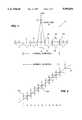
- FIG. 1is a graphical illustration of the correlation function at the output of a matched filter for an eleven chip Barker Code
- FIG. 2is a schematic block diagram illustrating an exemplary spread spectrum communication system in accordance with the prior art
- FIG. 3is a graphical illustration of the modulation of the sign and position of the main lobe, upon matched filtering, for an eleven chip spread spectrum code
- FIG. 4is a schematic block diagram of an illustrative spread spectrum position modulated transmitter according to the present invention.
- FIG. 5is a schematic block diagram of an illustrative spread spectrum position modulated receiver according to the present invention.
- the present inventionprovides a method and apparatus for modulating and demodulating a communication signal using spread spectrum encoding.
- the present inventionimproves on conventional spread spectrum modulation techniques by also modulating the position of the transmitted spread spectrum code which, upon matched filtering, modulates the position of the main lobe in the receiver output. In this manner, additional information may be conveyed per symbol duration.
- nthe frequency spectrum of a transmitted signal by a factor of n. This is typically accomplished by encoding each bit to be transmitted using a predefined codeword, or pattern, consisting of n "chips" or “signal elements" which are all transmitted in the time frame normally allocated for a single bit.
- the predefined codewordmay be utilized to represent a value of binary "0" and the inverse of the predefined codeword may be utilized to represent a value of binary "1".
- a bit of informationcan be conveyed by selecting from one of two predefined codewords.
- a number of spread spectrum codesconsisting of a number of consecutive positive and negative signal elements, have been discovered which have unique properties that optimize the detection of the transmitted information.
- a number of well known spread spectrum codeshave been discovered by Barker, Neuman-Hofman, and Williard.
- BarkerBarker
- Neuman-Hofmanand Williard.
- Ning Zhan and S. W. Golomb"Sixty Phase Generalized Barker Sequences," I.E.E.E. Trans. on Information Theory, Vol. 35, No. 4 (July, 1989), incorporated herein by reference.
- FIG. 1illustrates the output 10 of a matched filter for the well known 11 chip Barker code, which has a pattern of "+++---+--+-", corresponding to a binary value of "0". Since the amplitude of the main lobe 15 is eleven times greater in magnitude than the amplitude of any side lobe, such as the side lobes 21 and 23, the position of the main lobe 15 may be easily identified, even under possible change in polarity.
- each bit to be sent by a transmitter 205is first encoded by a spread spectrum encoder 210.
- the encoder 210is embodied as a Barker code generator, and a binary value of "1" is to be transmitted, the encoder 210 will generate a pattern of "---+++-++-+", which is the inverse Barker code.
- This information signalwill then be modulated in a conventional manner by modulator 220 prior to transmission over a transmission medium 230, which may be embodied as a conventional or wireless telecommunications network.
- the modulator 220may employ a modulation technique, for example, which multiplies the codeword by a sinusoidal carrier wave in order to shift the signal frequency upward to the carrier frequency. In this manner, the original signal spectrum may be translated into a particular frequency band allocated by the FCC, or another regulatory body.
- a modulation techniquefor example, which multiplies the codeword by a sinusoidal carrier wave in order to shift the signal frequency upward to the carrier frequency.
- the original signal spectrummay be translated into a particular frequency band allocated by the FCC, or another regulatory body.
- the frequency of the received signalis first shifted down to the base band signal by a demodulator 245, thus returning the signal to its original form prior to modulation. Thereafter, the received signal is passed through a filter 250 that is matched to the characteristics of the particular codeword.
- a decision device 260will identify whether the peaks associated with the main lobes at the output of the matched filter 250 have a positive or negative value.
- a positive main lobemay indicate a binary value of "0", and a negative main lobe may be utilized to indicate a binary value of "1".
- phase-shift keyingPSK
- QPSKquadrature phase-shift keying
- a positive or negative spread spectrum codewordIn a conventional spread spectrum code implementation, four possible signal states are achieved by modulating two orthogonal carrier signals, such as a sine and a cosine wave, by a positive or negative spread spectrum codeword.
- the sine wave modulated by a positive codewordcan represent a binary value of "1" of a first bit, and when modulated by a negative codeword can represent a binary value of "0".
- the concurrently transmitted cosine wave modulated by a positive codewordcan represent a binary value of "1" of a second bit, and when modulated by a negative codeword can represent a binary value of "0".
- two bits of informationmay be conveyed per bit duration.
- the cosine wave-modulated codewordis frequently referred to as the in-phase (I) signal
- the sine wave-modulated codewordis frequently referred to as the quadrature (Q) signal.
- the information rate that may be achieved with spread spectrum modulation techniquesmay be further increased by modulating the position of the main lobe associated with the transmitted codeword at the output of the matched filter.
- the eleven chip Barker codeupon matched filtering, will have a main lobe at position six that is one chip wide.
- additional informationcan be conveyed by manipulating the position of the main lobe, upon matched filtering, to appear in one of the other chip positions. If the position of the main lobe is varied among eight of the positions, eight signal states are available, and three additional bits may thereby be conveyed. Thus, one bit is conveyed by detecting the sign of the main lobe, and three additional bits are conveyed by detecting the position of the main lobe, for a total of four bits conveyed per symbol duration.
- the codewordis modulated by two orthogonal carrier signals, such as a sine and a cosine wave, as discussed above, a total of eight bits may thus be conveyed.
- a plurality of independently generated codewordsmay each be modulated by a respectively distinct carrier signal having a unique phase, amplitude or frequency. It is further noted that if a spread spectrum codeword having at least 16 chips is utilized, 16 signal states are available, and thus four additional bits of information could be conveyed for each codeword by modulating the position of the main lobe among 16 available positions.
- FIG. 3provides a graphical representation of the modulation of the sign and position for an eleven-chip spread spectrum code using two orthogonal carrier signals, I and Q.
- the position of the main lobeis manipulated to occupy one of eight available chip positions. Accordingly, the main lobe of the I signal may be positive or negative and occupy one of eight positions. Similarly, the main lobe of the Q signal may be positive or negative and occupy one of eight positions.
- Bullet points 310 and 320are utilized in FIG. 3 to indicate the sign and position of the I and Q signals.
- the I signalis positive, and is at location one, as shown by bullet point 310, while the Q signal is positive and is at location five, as shown by bullet point 320.
- the illustrative embodimentmay be utilized to convey eight bits of information.
- the position of the main lobeupon matched filtering, may be manipulated within the defined symbol period by delaying the transmission of the codeword, by a positive or negative time period.
- the codeword generatorshould delay the transmission of the codeword by 2/11 of the symbol period.
- the codeword generatorshould advance the transmission of the codeword by 4/11 of the symbol period.
- ISIintersymbol interference
- the additional unused positionsserve as a guard band or buffer for purposes of further minimizing intersymbol interference.
- FIG. 4is an exemplary implementation of a spread spectrum position modulated transmitter 400 in accordance with the present invention.
- the bits to be sent by the transmitter 400are first encoded by an encoder 410.
- the encoder 410will calculate the sign of the I and Q signals, I sgn and Q sgn ; in other words, whether the I and Q pulses, respectively, should have positive or negative pulses.
- the encoder 410will calculate the position of the I and Q signals, I pos and Q pos .
- the values I pos and Q poscan be positive or negative time delay values, and indicate the time at which the respective spread spectrum code generators 420, 440, discussed below, should generate the spread spectrum code relative to the symbol duration period.
- the encoder 410 and the spread spectrum code generators 420, 440each operate according to the timing information that is received from the timing generator 430, which will generate time pulses in accordance with the symbol duration period, as appropriate for the preselected spread spectrum codeword. Specifically, in the illustrative embodiment, the encoder 410 will read in eight data bits to be transmitted for each indicated symbol duration period.
- the encoder 410will calculate the I sgn , Q sgn , I pos and Q pos values, preferably in a Gray encoded manner.
- the encoder 410preferably Gray-encodes in each coordinate, such that opposite binary input data sequences are allocated to opposite polarity Barker codes. For example, if the following sequences are allocated to I-position three and Q-position five, then the following sequences are allocated to:
- the spread spectrum code generators 420, 440will receive the appropriate time delay value, either I pos or Q pos , and will then generate the spread spectrum codeword in accordance with the calculated delay value, relative to the spread spectrum symbol interval center. In this manner, the main lobes of the I and Q signals will be shifted appropriately, in order to convey the desired information.
- the time-shifted codewords generated by the spread spectrum code generators 420, 440will be multiplied by the polarity values indicated by the I sgn and Q sgn values, respectively, by the mixers 445 and 450.
- the output of the mixers 445 and 450will be the two information carrying signals, in other words, the positive or negative values of the time-shifted spread spectrum codeword, as appropriate.
- the information carrying signalswill then be modulated in a conventional manner by modulator 455 prior to transmission.
- the modulator 455may employ a modulation technique, for example, which multiplies the I signal time-shifted codeword by a cosine wave using mixer 465, and the Q signal time-shifted codeword by a sine wave using mixer 470.
- the signal frequencies of the original information signalsare shifted upward to the carrier frequency associated with the carrier oscillator 460, which may, for example, be in a particular frequency band allocated by the FCC, or another regulatory body.
- the modulated I and Q signalswill then be combined using an adder 475, before passing through conventional RF stages 480, which serve to amplify the modulated signals. Thereafter, the combined modulated I and Q signals may be transmitted over a transmission medium 485 to a receiver 500, discussed below in conjunction with FIG. 5.
- the transmission medium 485may be embodied as a wired or a wireless telecommunications network.
- FIG. 5is an exemplary implementation of a spread spectrum position modulated receiver 500 in accordance with the present invention.
- the frequency of the received signalfirst passes through RF and IF stages 510, which serve to filter the received signal from the adjacent channel interference and to amplify the received signal. Thereafter, the frequency of the received signal is shifted down to the base band signal by a conventional demodulator 520, in order to return the received signal to its original form prior to modulation.
- the I modulated signalis returned to baseband by multiplying it with a cosine wave, generated by carrier oscillator 530, using mixer 525, in order to isolate the I signal time-shifted codeword.
- the Q modulated signalis returned to baseband by multiplying it with a sine wave, using mixer 535, in order to isolate the Q signal time-shifted codeword.
- the demodulated I signal time-shifted codeword and the Q signal time-shifted codewordare then passed through spread spectrum code decorrelators 540 and 545, respectively.
- the spread spectrum code decorrelators 540 and 545are filters matched to the preselected codeword, in a known manner.
- the output of the spread spectrum code decorrelators 540 and 545will be the correlation function of each signal, similar to the correlation function illustrated in FIG. 1 for an eleven chip Barker code. Due to the effects of delay spread, however, the main lobe and side lobes may be spread into the time period of an adjacent symbol, over the inherent spreading due to the Barker code side lobes themselves.
- the I and Q signalsare preferably conditioned by complex channel conditioners 550 and 555, respectively, which serve to compensate for the delay spread of the communication channels, in a known manner.
- the complex channel conditioners 550 and 555may be embodied as a complex equalizer, of known type, or as filters which are matched to the particular delay spread characteristics of the communication channel, for example, by measuring the channel impulse by using a preamble signal before transmitting the data.
- the conditioned I and Q signals, I c and Q cmay then be analyzed to identify the sign and the position of each main lobe.
- the eight chip positions of the I and Q signals that are utilized to convey informationare preferably sampled and stored using eight-position registers 560 and 565, respectively.
- each position of the register 560, 565will contain the amplitude value of the corresponding chip position of the I and Q signals.
- the values stored in the positions of the registers 560 and 565are analyzed by a decision device 570 in order to detect the sign and position of the main lobes of the I and Q signals and translate this information into the appropriate eight bit binary word.
- the decision device 570identifies the sign and position of the main lobe of the I and Q signals by selecting the largest stored amplitude value in each of the registers 560 and 565, respectively.
- the sign of the main lobe of the I signalconveys one bit, and the position of the main lobe conveys an additional 3 bits.
- the sign of the main lobe of the Q signalconveys one bit, and the position of the main lobe conveys an additional 3 bits.
- a total of eight bits of informationare conveyed.
- the coupling coefficientscan be taken into account in a more complex decision device 570.
Landscapes
- Engineering & Computer Science (AREA)
- Computer Networks & Wireless Communication (AREA)
- Signal Processing (AREA)
- Digital Transmission Methods That Use Modulated Carrier Waves (AREA)
- Dc Digital Transmission (AREA)
Abstract
Description
______________________________________ Binary Sequence I, O Polarity ______________________________________ 00100100 +I, +Q 00100101 +I, -Q 00100110 -I, +Q 00100111 -I, -Q. ______________________________________
Claims (20)
Priority Applications (7)
| Application Number | Priority Date | Filing Date | Title |
|---|---|---|---|
| US08/298,260US5596601A (en) | 1994-08-30 | 1994-08-30 | Method and apparatus for spread spectrum code pulse position modulation |
| US08/345,110US5623511A (en) | 1994-08-30 | 1994-11-28 | Spread spectrum code pulse position modulated receiver having delay spread compensation |
| CA002153711ACA2153711A1 (en) | 1994-08-30 | 1995-07-12 | Method and apparatus for spread spectrum code pulse position modulation |
| EP95305906AEP0700170B1 (en) | 1994-08-30 | 1995-08-23 | A method and apparatus for spread spectrum code pulse position modulation |
| DE69535852TDE69535852D1 (en) | 1994-08-30 | 1995-08-23 | Method and apparatus for spread spectrum pulse position modulation |
| JP22123595AJP3778969B2 (en) | 1994-08-30 | 1995-08-30 | Method and apparatus for spread spectrum code pulse position modulation |
| CA 2159134CA2159134C (en) | 1994-08-30 | 1995-09-26 | Spread spectrum code pulse position modulated receiver having delay spread compensation |
Applications Claiming Priority (1)
| Application Number | Priority Date | Filing Date | Title |
|---|---|---|---|
| US08/298,260US5596601A (en) | 1994-08-30 | 1994-08-30 | Method and apparatus for spread spectrum code pulse position modulation |
Related Child Applications (1)
| Application Number | Title | Priority Date | Filing Date |
|---|---|---|---|
| US08/345,110Continuation-In-PartUS5623511A (en) | 1994-08-30 | 1994-11-28 | Spread spectrum code pulse position modulated receiver having delay spread compensation |
Publications (1)
| Publication Number | Publication Date |
|---|---|
| US5596601Atrue US5596601A (en) | 1997-01-21 |
Family
ID=23149746
Family Applications (1)
| Application Number | Title | Priority Date | Filing Date |
|---|---|---|---|
| US08/298,260Expired - LifetimeUS5596601A (en) | 1994-08-30 | 1994-08-30 | Method and apparatus for spread spectrum code pulse position modulation |
Country Status (5)
| Country | Link |
|---|---|
| US (1) | US5596601A (en) |
| EP (1) | EP0700170B1 (en) |
| JP (1) | JP3778969B2 (en) |
| CA (1) | CA2153711A1 (en) |
| DE (1) | DE69535852D1 (en) |
Cited By (37)
| Publication number | Priority date | Publication date | Assignee | Title |
|---|---|---|---|---|
| US5859870A (en)* | 1995-10-23 | 1999-01-12 | Nec Corporation | Time diversity transmission-reception system |
| US5923701A (en)* | 1996-05-24 | 1999-07-13 | Ricoh Company, Ltd. | Spread spectrum pulse position modulation system |
| US6041074A (en)* | 1996-05-24 | 2000-03-21 | Ricoh Company, Ltd. | Spread spectrum pulse position modulation system |
| US6047016A (en)* | 1997-06-23 | 2000-04-04 | Cellnet Data Systems, Inc. | Processing a spread spectrum signal in a frequency adjustable system |
| US6055266A (en)* | 1996-08-09 | 2000-04-25 | Ricoh Company, Ltd. | Spread spectrum pulse position modulation communication system |
| US6115411A (en)* | 1996-12-31 | 2000-09-05 | Lucent Technologies, Inc. | System and method for spread spectrum code position modulation and wireless local area network employing the same |
| US6178197B1 (en) | 1997-06-23 | 2001-01-23 | Cellnet Data Systems, Inc. | Frequency discrimination in a spread spectrum signal processing system |
| US6192068B1 (en) | 1996-10-03 | 2001-02-20 | Wi-Lan Inc. | Multicode spread spectrum communications system |
| US6307877B1 (en)* | 1995-10-04 | 2001-10-23 | Imec | Programmable modem apparatus for transmitting and receiving digital data, design method and use method for the modem |
| US6331997B1 (en)* | 1998-08-04 | 2001-12-18 | Linkair Communication, Inc. | Scheme for spread spectrum multiple access coding |
| US6351246B1 (en) | 1999-05-03 | 2002-02-26 | Xtremespectrum, Inc. | Planar ultra wide band antenna with integrated electronics |
| US20020057727A1 (en)* | 2001-02-21 | 2002-05-16 | Daoben Li | Code-division-multiple-access transmitter with zero correlation window |
| US20020064212A1 (en)* | 2001-02-21 | 2002-05-30 | Daoben Li | Code-division-multiple-access receiver with zero correlation window |
| USRE37802E1 (en) | 1992-03-31 | 2002-07-23 | Wi-Lan Inc. | Multicode direct sequence spread spectrum |
| US6426978B1 (en)* | 1998-10-01 | 2002-07-30 | Ericsson Inc. | Digital communication systems and methods for differential and/or amplitude encoding and decoding secondary symbols |
| US6456644B1 (en) | 1997-06-23 | 2002-09-24 | Cellnet Data Systems, Inc. | Bandpass correlation of a spread spectrum signal |
| US6480503B1 (en)* | 1998-12-28 | 2002-11-12 | Texas Instruments Incorporated | Turbo-coupled multi-code multiplex data transmission for CDMA |
| US20020176511A1 (en)* | 2001-03-16 | 2002-11-28 | Fullerton Larry W. | High pulse-rate radio-frequency apparatus and associated methods |
| US20030053554A1 (en)* | 1997-12-12 | 2003-03-20 | Xtreme Spectrum, Inc. | Ultra wide bandwidth spread-spectrum communications system |
| US20030067964A1 (en)* | 2000-02-10 | 2003-04-10 | Daoben Li | Code-division-multiple-access system using zero correlation window |
| US6560272B1 (en)* | 1998-08-03 | 2003-05-06 | Nec Corporation | Decode circuit for code division multiple access receiver |
| US20030118083A1 (en)* | 2000-02-10 | 2003-06-26 | Daoben Li | Large area wireless CDMA system and method |
| US6590545B2 (en) | 2000-08-07 | 2003-07-08 | Xtreme Spectrum, Inc. | Electrically small planar UWB antenna apparatus and related system |
| US6628699B2 (en) | 1997-06-23 | 2003-09-30 | Schlumberger Resource Management Systems, Inc. | Receiving a spread spectrum signal |
| US20040062321A1 (en)* | 1997-04-17 | 2004-04-01 | Takehiro Nakamura | Base station apparatus of mobile communication system |
| US6717916B1 (en)* | 1997-07-25 | 2004-04-06 | Samsung Electronics Co., Ltd. | Method and apparatus for initializing a packet traffic channel in a communication system |
| US20040076161A1 (en)* | 1999-01-08 | 2004-04-22 | Lavian Tal I. | Dynamic assignment of traffic classes to a priority queue in a packet forwarding device |
| US6741638B2 (en) | 1997-06-23 | 2004-05-25 | Schlumbergersema Inc. | Bandpass processing of a spread spectrum signal |
| US6744807B1 (en) | 2000-05-31 | 2004-06-01 | University Of Pretoria | Multi-dimensional spread spectrum modem |
| US6763058B1 (en)* | 2000-06-27 | 2004-07-13 | Northrop Grumman Corporation | Low signal to noise ratio acquisition and link characterization techniques for VSAT spread spectrum modems |
| US20050100081A1 (en)* | 2003-10-01 | 2005-05-12 | Spectrum5, Inc. | Equalizer with decision feedback frequency tracking and bit decoding for spread spectrum communications |
| US20050168324A1 (en)* | 2004-02-03 | 2005-08-04 | Atmel Germany Gmbh | Method and circuit arrangement for wireless data transmission |
| US20050240607A1 (en)* | 1999-10-28 | 2005-10-27 | Lightwaves Systems, Inc. | Method of transmitting data including a structured linear database |
| KR100511671B1 (en)* | 1997-05-29 | 2005-10-31 | 엘지전자 주식회사 | PN Code Generator for Orthogonal Spread of Code Division Multiple Access Systems |
| US20080136644A1 (en)* | 1998-12-11 | 2008-06-12 | Freescale Semiconductor Inc. | Method and system for performing distance measuring and direction finding using ultrawide bandwitdh transmissions |
| US20110154148A1 (en)* | 2009-12-23 | 2011-06-23 | Bernard Arambepola | Spectral content based decoding and frequency offset estimation |
| US8275077B1 (en)* | 2010-10-13 | 2012-09-25 | The United States Of America As Represented By The Director, National Security Agency | Coherent demodulation of ais-GMSK signals in co-channel |
Families Citing this family (7)
| Publication number | Priority date | Publication date | Assignee | Title |
|---|---|---|---|---|
| DE69634974D1 (en)* | 1995-12-26 | 2005-09-01 | Sharp Kk | Spreizspektrumnachrichtenübertragungssystem |
| CN1049312C (en)* | 1997-08-12 | 2000-02-09 | 李道本 | Spread spectrum address coding technique |
| JP3380446B2 (en)* | 1997-10-20 | 2003-02-24 | 株式会社鷹山 | Receiver for CDMA communication system |
| KR100685949B1 (en) | 2001-12-22 | 2007-02-23 | 엘지.필립스 엘시디 주식회사 | LCD and its manufacturing method |
| JP5472850B2 (en)* | 2009-09-07 | 2014-04-16 | 独立行政法人情報通信研究機構 | Pulse position modulation noise confidential communication system |
| ES2700539T3 (en)* | 2013-05-14 | 2019-02-18 | Broadnet Invest AG | Signal representing data, method and device for generating such signal and method and device for determining the data represented from such signal |
| KR102635532B1 (en)* | 2017-02-03 | 2024-02-08 | 삼성전자주식회사 | Method and apparatus for transmitting and receiving a signal using polar coding in a communication system |
Citations (3)
| Publication number | Priority date | Publication date | Assignee | Title |
|---|---|---|---|---|
| US5157686A (en)* | 1990-05-24 | 1992-10-20 | Cylink Corporation | Method and apparatus for the modulation of spread spectrum radio signals |
| US5166952A (en)* | 1990-05-24 | 1992-11-24 | Cylink Corporation | Method and apparatus for the reception and demodulation of spread spectrum radio signals |
| WO1995012939A1 (en)* | 1993-11-01 | 1995-05-11 | Omnipoint Corporation | Pulse position modulation with spread spectrum |
Family Cites Families (2)
| Publication number | Priority date | Publication date | Assignee | Title |
|---|---|---|---|---|
| US5103459B1 (en)* | 1990-06-25 | 1999-07-06 | Qualcomm Inc | System and method for generating signal waveforms in a cdma cellular telephone system |
| US5313457A (en)* | 1992-04-14 | 1994-05-17 | Trimble Navigation Limited | Code position modulation system and method for multiple user satellite communications |
- 1994
- 1994-08-30USUS08/298,260patent/US5596601A/ennot_activeExpired - Lifetime
- 1995
- 1995-07-12CACA002153711Apatent/CA2153711A1/ennot_activeAbandoned
- 1995-08-23DEDE69535852Tpatent/DE69535852D1/ennot_activeExpired - Lifetime
- 1995-08-23EPEP95305906Apatent/EP0700170B1/ennot_activeExpired - Lifetime
- 1995-08-30JPJP22123595Apatent/JP3778969B2/ennot_activeExpired - Lifetime
Patent Citations (3)
| Publication number | Priority date | Publication date | Assignee | Title |
|---|---|---|---|---|
| US5157686A (en)* | 1990-05-24 | 1992-10-20 | Cylink Corporation | Method and apparatus for the modulation of spread spectrum radio signals |
| US5166952A (en)* | 1990-05-24 | 1992-11-24 | Cylink Corporation | Method and apparatus for the reception and demodulation of spread spectrum radio signals |
| WO1995012939A1 (en)* | 1993-11-01 | 1995-05-11 | Omnipoint Corporation | Pulse position modulation with spread spectrum |
Non-Patent Citations (7)
| Title |
|---|
| Okazaki, I., and Hasegawa, T., "Spread Spectrum Pulse Position Modulation and Its Asynchronous CDMA Performance--A Simple Approach For Shannon's Limit--," IEEE Second International Symposium on Spread Spectrum Techniques and Applications, Nov. 29-Dec. 2, 1992, Yokohama, Japan, pp. 325-328. |
| Okazaki, I., and Hasegawa, T., "Spread Spectrum Pulse Position Modulation--A Simple Approach for Shannon's Limit--," Singapore ICCS/ISITA '92, Nov. 16-20, 1992, Singapore, pp. 300-304. |
| Okazaki, I., and Hasegawa, T., Spread Spectrum Pulse Position Modulation A Simple Approach for Shannon s Limit , Singapore ICCS/ISITA 92, Nov. 16 20, 1992, Singapore, pp. 300 304.* |
| Okazaki, I., and Hasegawa, T., Spread Spectrum Pulse Position Modulation and Its Asynchronous CDMA Performance A Simple Approach For Shannon s Limit , IEEE Second International Symposium on Spread Spectrum Techniques and Applications, Nov. 29 Dec. 2, 1992, Yokohama, Japan, pp. 325 328.* |
| U.S. patent application Ser. No. 08/146,490, dated Nov. 1, 1993, (not enclosed).* |
| Zhang, N., and Golomb, S. W., "Sixty Phase Generalized Barker Sequences," IEEE Trans. on Information Theory, vol. 35, No. 4, (Jul. 1989), pp. 911-912. |
| Zhang, N., and Golomb, S. W., Sixty Phase Generalized Barker Sequences, IEEE Trans. on Information Theory, vol. 35, No. 4, (Jul. 1989), pp. 911 912.* |
Cited By (68)
| Publication number | Priority date | Publication date | Assignee | Title |
|---|---|---|---|---|
| USRE37802E1 (en) | 1992-03-31 | 2002-07-23 | Wi-Lan Inc. | Multicode direct sequence spread spectrum |
| US6898233B2 (en) | 1995-10-04 | 2005-05-24 | Imec Vzw | Programmable modem apparatus for transmitting and receiving digital data, design method and use method for the modem |
| US6307877B1 (en)* | 1995-10-04 | 2001-10-23 | Imec | Programmable modem apparatus for transmitting and receiving digital data, design method and use method for the modem |
| US6597727B2 (en) | 1995-10-04 | 2003-07-22 | Imec Vzw | Programmable modem apparatus for transmitting and receiving digital data, design method and use method for the modem |
| US5859870A (en)* | 1995-10-23 | 1999-01-12 | Nec Corporation | Time diversity transmission-reception system |
| US5923701A (en)* | 1996-05-24 | 1999-07-13 | Ricoh Company, Ltd. | Spread spectrum pulse position modulation system |
| US6041074A (en)* | 1996-05-24 | 2000-03-21 | Ricoh Company, Ltd. | Spread spectrum pulse position modulation system |
| US6055266A (en)* | 1996-08-09 | 2000-04-25 | Ricoh Company, Ltd. | Spread spectrum pulse position modulation communication system |
| US6205169B1 (en) | 1996-08-09 | 2001-03-20 | Ricoh Company, Ltd. | Spread spectrum pulse position modulation communication system |
| US6192068B1 (en) | 1996-10-03 | 2001-02-20 | Wi-Lan Inc. | Multicode spread spectrum communications system |
| US6320897B1 (en) | 1996-10-03 | 2001-11-20 | Wi-Lan Inc. | Multicode spread spectrum communications system |
| US6115411A (en)* | 1996-12-31 | 2000-09-05 | Lucent Technologies, Inc. | System and method for spread spectrum code position modulation and wireless local area network employing the same |
| US20060251151A1 (en)* | 1997-04-17 | 2006-11-09 | Ntt Docomo, Inc. | Base station apparatus of mobile communication system |
| US20040085916A1 (en)* | 1997-04-17 | 2004-05-06 | Takehiro Nakamura | Base station apparatus of mobile communication system |
| US8005120B2 (en) | 1997-04-17 | 2011-08-23 | Ntt Docomo, Inc. | Base station apparatus of mobile communication system |
| US7826861B2 (en) | 1997-04-17 | 2010-11-02 | Ntt Docomo, Inc. | Base station apparatus of mobile communication system |
| US7672357B2 (en) | 1997-04-17 | 2010-03-02 | Ntt Docomo, Inc. | Base station apparatus of mobile communication system |
| US20040136336A1 (en)* | 1997-04-17 | 2004-07-15 | Takehiro Nakamura | Base station apparatus of mobile communication system |
| US7443907B2 (en) | 1997-04-17 | 2008-10-28 | Ntt Docomo, Inc. | Base station apparatus of mobile communication system |
| US6782035B1 (en) | 1997-04-17 | 2004-08-24 | Ntt Docomo Inc. | Base station apparatus of mobile communication system |
| US20040076125A1 (en)* | 1997-04-17 | 2004-04-22 | Takehiro Nakamura | Base station apparatus of mobile communication system |
| US20040071192A1 (en)* | 1997-04-17 | 2004-04-15 | Takehiro Nakamura | Base station apparatus of mobile communication system |
| US20070121706A1 (en)* | 1997-04-17 | 2007-05-31 | Ntt Docomo, Inc. | Base station apparatus of mobile communication system |
| US20040071220A1 (en)* | 1997-04-17 | 2004-04-15 | Takehiro Nakamura | Base station apparatus of mobile communication system |
| US20040071248A1 (en)* | 1997-04-17 | 2004-04-15 | Takehiro Nakamura | Base station apparatus of mobile communication system |
| US7095780B2 (en) | 1997-04-17 | 2006-08-22 | Ntt Docomo, Inc. | Base station apparatus of mobile communication system |
| US20040062321A1 (en)* | 1997-04-17 | 2004-04-01 | Takehiro Nakamura | Base station apparatus of mobile communication system |
| KR100511671B1 (en)* | 1997-05-29 | 2005-10-31 | 엘지전자 주식회사 | PN Code Generator for Orthogonal Spread of Code Division Multiple Access Systems |
| US6628699B2 (en) | 1997-06-23 | 2003-09-30 | Schlumberger Resource Management Systems, Inc. | Receiving a spread spectrum signal |
| US6741638B2 (en) | 1997-06-23 | 2004-05-25 | Schlumbergersema Inc. | Bandpass processing of a spread spectrum signal |
| US6456644B1 (en) | 1997-06-23 | 2002-09-24 | Cellnet Data Systems, Inc. | Bandpass correlation of a spread spectrum signal |
| US6178197B1 (en) | 1997-06-23 | 2001-01-23 | Cellnet Data Systems, Inc. | Frequency discrimination in a spread spectrum signal processing system |
| US6047016A (en)* | 1997-06-23 | 2000-04-04 | Cellnet Data Systems, Inc. | Processing a spread spectrum signal in a frequency adjustable system |
| US6717916B1 (en)* | 1997-07-25 | 2004-04-06 | Samsung Electronics Co., Ltd. | Method and apparatus for initializing a packet traffic channel in a communication system |
| US20030053555A1 (en)* | 1997-12-12 | 2003-03-20 | Xtreme Spectrum, Inc. | Ultra wide bandwidth spread-spectrum communications system |
| US20030053554A1 (en)* | 1997-12-12 | 2003-03-20 | Xtreme Spectrum, Inc. | Ultra wide bandwidth spread-spectrum communications system |
| US6931078B2 (en) | 1997-12-12 | 2005-08-16 | Freescale Semiconductor, Inc. | Ultra wide bandwidth spread-spectrum communications systems |
| US7408973B2 (en) | 1997-12-12 | 2008-08-05 | Freescale Semiconductor, Inc. | Ultra wide bandwidth spread-spectrum communications system |
| US6700939B1 (en) | 1997-12-12 | 2004-03-02 | Xtremespectrum, Inc. | Ultra wide bandwidth spread-spectrum communications system |
| US6901112B2 (en) | 1997-12-12 | 2005-05-31 | Freescale Semiconductor, Inc. | Ultra wide bandwidth spread-spectrum communications system |
| US20050259720A1 (en)* | 1997-12-12 | 2005-11-24 | Freescale Semiconductor, Inc. | Ultra wide bandwidth spread-spectrum communications system |
| US6560272B1 (en)* | 1998-08-03 | 2003-05-06 | Nec Corporation | Decode circuit for code division multiple access receiver |
| US6331997B1 (en)* | 1998-08-04 | 2001-12-18 | Linkair Communication, Inc. | Scheme for spread spectrum multiple access coding |
| US6426978B1 (en)* | 1998-10-01 | 2002-07-30 | Ericsson Inc. | Digital communication systems and methods for differential and/or amplitude encoding and decoding secondary symbols |
| US20080136644A1 (en)* | 1998-12-11 | 2008-06-12 | Freescale Semiconductor Inc. | Method and system for performing distance measuring and direction finding using ultrawide bandwitdh transmissions |
| US8451936B2 (en) | 1998-12-11 | 2013-05-28 | Freescale Semiconductor, Inc. | Method and system for performing distance measuring and direction finding using ultrawide bandwidth transmissions |
| US7616676B2 (en) | 1998-12-11 | 2009-11-10 | Freescale Semiconductor, Inc. | Method and system for performing distance measuring and direction finding using ultrawide bandwidth transmissions |
| US6480503B1 (en)* | 1998-12-28 | 2002-11-12 | Texas Instruments Incorporated | Turbo-coupled multi-code multiplex data transmission for CDMA |
| US20040076161A1 (en)* | 1999-01-08 | 2004-04-22 | Lavian Tal I. | Dynamic assignment of traffic classes to a priority queue in a packet forwarding device |
| US6351246B1 (en) | 1999-05-03 | 2002-02-26 | Xtremespectrum, Inc. | Planar ultra wide band antenna with integrated electronics |
| US7983146B2 (en)* | 1999-10-28 | 2011-07-19 | Lightwaves Systems, Inc. | Method for communications using a communication protocol |
| US20050240607A1 (en)* | 1999-10-28 | 2005-10-27 | Lightwaves Systems, Inc. | Method of transmitting data including a structured linear database |
| US6636556B2 (en) | 2000-02-10 | 2003-10-21 | Linkair Communications, Inc. | Large area wireless CDMA system and method |
| US20030118083A1 (en)* | 2000-02-10 | 2003-06-26 | Daoben Li | Large area wireless CDMA system and method |
| US20030067964A1 (en)* | 2000-02-10 | 2003-04-10 | Daoben Li | Code-division-multiple-access system using zero correlation window |
| US6744807B1 (en) | 2000-05-31 | 2004-06-01 | University Of Pretoria | Multi-dimensional spread spectrum modem |
| US6763058B1 (en)* | 2000-06-27 | 2004-07-13 | Northrop Grumman Corporation | Low signal to noise ratio acquisition and link characterization techniques for VSAT spread spectrum modems |
| US6590545B2 (en) | 2000-08-07 | 2003-07-08 | Xtreme Spectrum, Inc. | Electrically small planar UWB antenna apparatus and related system |
| US20020057727A1 (en)* | 2001-02-21 | 2002-05-16 | Daoben Li | Code-division-multiple-access transmitter with zero correlation window |
| US20020064212A1 (en)* | 2001-02-21 | 2002-05-30 | Daoben Li | Code-division-multiple-access receiver with zero correlation window |
| US20020176511A1 (en)* | 2001-03-16 | 2002-11-28 | Fullerton Larry W. | High pulse-rate radio-frequency apparatus and associated methods |
| US20050100081A1 (en)* | 2003-10-01 | 2005-05-12 | Spectrum5, Inc. | Equalizer with decision feedback frequency tracking and bit decoding for spread spectrum communications |
| US7236510B2 (en) | 2003-10-01 | 2007-06-26 | S5 Wireless, Inc. | Equalizer with decision feedback frequency tracking and bit decoding for spread spectrum communications |
| US20050168324A1 (en)* | 2004-02-03 | 2005-08-04 | Atmel Germany Gmbh | Method and circuit arrangement for wireless data transmission |
| US7342481B2 (en)* | 2004-02-03 | 2008-03-11 | Atmel Germany, Gmbh | Method and circuit arrangement for wireless data transmission |
| US20110154148A1 (en)* | 2009-12-23 | 2011-06-23 | Bernard Arambepola | Spectral content based decoding and frequency offset estimation |
| US8392802B2 (en)* | 2009-12-23 | 2013-03-05 | Intel Corporation | Spectral content based decoding and frequency offset estimation |
| US8275077B1 (en)* | 2010-10-13 | 2012-09-25 | The United States Of America As Represented By The Director, National Security Agency | Coherent demodulation of ais-GMSK signals in co-channel |
Also Published As
| Publication number | Publication date |
|---|---|
| EP0700170A3 (en) | 2000-03-29 |
| EP0700170A2 (en) | 1996-03-06 |
| DE69535852D1 (en) | 2008-11-20 |
| EP0700170B1 (en) | 2008-10-08 |
| CA2153711A1 (en) | 1996-03-01 |
| JP3778969B2 (en) | 2006-05-24 |
| JPH0879133A (en) | 1996-03-22 |
Similar Documents
| Publication | Publication Date | Title |
|---|---|---|
| US5596601A (en) | Method and apparatus for spread spectrum code pulse position modulation | |
| US5623511A (en) | Spread spectrum code pulse position modulated receiver having delay spread compensation | |
| US7079567B2 (en) | Digital modulation system using extended code set | |
| US7787355B2 (en) | M-ary orthogonal keying system | |
| US7583582B2 (en) | M-ary orthogonal keying system | |
| JP3406319B2 (en) | High-speed data transmission wireless local area network | |
| RU2120189C1 (en) | Quadrature multiplexing of two data signals which are extended by means of different pn-sequences | |
| KR100814155B1 (en) | Code division multiple access wireless system with time reversed space time block transmitter diversity encoding | |
| JP2007517465A (en) | Hybrid spread spectrum radio system | |
| US6674790B1 (en) | System and method employing concatenated spreading sequences to provide data modulated spread signals having increased data rates with extended multi-path delay spread | |
| EP1198904A1 (en) | Transmit diversity transmitter and receiver for radio communications systems | |
| US6363100B1 (en) | Radio data communication system using spread spectrum scheme | |
| KR20030078966A (en) | System for code division multi-access communication | |
| US20010026578A1 (en) | Code division multiple access transmitter and receiver | |
| KR100464586B1 (en) | Spread Spectrum Multiple Access Coding | |
| WO1995001016A1 (en) | Method for selectively receiving spread spectrum signal on chip basis | |
| US6219356B1 (en) | Method for multipath resistant waveform coding for high speed wireless data transmission | |
| CA2159134C (en) | Spread spectrum code pulse position modulated receiver having delay spread compensation | |
| AU2388199A (en) | Digital modulation system using extended code set |
Legal Events
| Date | Code | Title | Description |
|---|---|---|---|
| AS | Assignment | Owner name:AT&T CORP., NEW YORK Free format text:ASSIGNMENT OF ASSIGNORS INTEREST;ASSIGNOR:BAR-DAVID, ISRAEL;REEL/FRAME:007238/0719 Effective date:19940916 | |
| AS | Assignment | Owner name:LUCENT TECHNOLOGIES INC., NEW JERSEY Free format text:ASSIGNMENT OF ASSIGNORS INTEREST;ASSIGNOR:AT&T CORP.;REEL/FRAME:008196/0181 Effective date:19960329 | |
| STCF | Information on status: patent grant | Free format text:PATENTED CASE | |
| FEPP | Fee payment procedure | Free format text:PAYOR NUMBER ASSIGNED (ORIGINAL EVENT CODE: ASPN); ENTITY STATUS OF PATENT OWNER: LARGE ENTITY | |
| FPAY | Fee payment | Year of fee payment:4 | |
| AS | Assignment | Owner name:THE CHASE MANHATTAN BANK, AS COLLATERAL AGENT, TEX Free format text:CONDITIONAL ASSIGNMENT OF AND SECURITY INTEREST IN PATENT RIGHTS;ASSIGNOR:LUCENT TECHNOLOGIES INC. (DE CORPORATION);REEL/FRAME:011722/0048 Effective date:20010222 | |
| FPAY | Fee payment | Year of fee payment:8 | |
| AS | Assignment | Owner name:LUCENT TECHNOLOGIES INC., NEW JERSEY Free format text:TERMINATION AND RELEASE OF SECURITY INTEREST IN PATENT RIGHTS;ASSIGNOR:JPMORGAN CHASE BANK, N.A. (FORMERLY KNOWN AS THE CHASE MANHATTAN BANK), AS ADMINISTRATIVE AGENT;REEL/FRAME:018584/0446 Effective date:20061130 | |
| FPAY | Fee payment | Year of fee payment:12 | |
| AS | Assignment | Owner name:CREDIT SUISSE AG, NEW YORK Free format text:SECURITY INTEREST;ASSIGNOR:ALCATEL-LUCENT USA INC.;REEL/FRAME:030510/0627 Effective date:20130130 | |
| AS | Assignment | Owner name:ALCATEL-LUCENT USA INC., NEW JERSEY Free format text:RELEASE BY SECURED PARTY;ASSIGNOR:CREDIT SUISSE AG;REEL/FRAME:033949/0531 Effective date:20140819 |