US5596485A - Plastic packaged integrated circuit with heat spreader - Google Patents
Plastic packaged integrated circuit with heat spreaderDownload PDFInfo
- Publication number
- US5596485A US5596485AUS08/405,462US40546295AUS5596485AUS 5596485 AUS5596485 AUS 5596485AUS 40546295 AUS40546295 AUS 40546295AUS 5596485 AUS5596485 AUS 5596485A
- Authority
- US
- United States
- Prior art keywords
- heat spreader
- encapsulant
- integrated circuit
- thermally conductive
- conductive plate
- Prior art date
- Legal status (The legal status is an assumption and is not a legal conclusion. Google has not performed a legal analysis and makes no representation as to the accuracy of the status listed.)
- Expired - Lifetime
Links
Images


Classifications
- H—ELECTRICITY
- H01—ELECTRIC ELEMENTS
- H01L—SEMICONDUCTOR DEVICES NOT COVERED BY CLASS H10
- H01L23/00—Details of semiconductor or other solid state devices
- H01L23/34—Arrangements for cooling, heating, ventilating or temperature compensation ; Temperature sensing arrangements
- H01L23/36—Selection of materials, or shaping, to facilitate cooling or heating, e.g. heatsinks
- H01L23/367—Cooling facilitated by shape of device
- H—ELECTRICITY
- H01—ELECTRIC ELEMENTS
- H01L—SEMICONDUCTOR DEVICES NOT COVERED BY CLASS H10
- H01L23/00—Details of semiconductor or other solid state devices
- H01L23/34—Arrangements for cooling, heating, ventilating or temperature compensation ; Temperature sensing arrangements
- H01L23/40—Mountings or securing means for detachable cooling or heating arrangements ; fixed by friction, plugs or springs
- H—ELECTRICITY
- H01—ELECTRIC ELEMENTS
- H01L—SEMICONDUCTOR DEVICES NOT COVERED BY CLASS H10
- H01L23/00—Details of semiconductor or other solid state devices
- H01L23/34—Arrangements for cooling, heating, ventilating or temperature compensation ; Temperature sensing arrangements
- H01L23/42—Fillings or auxiliary members in containers or encapsulations selected or arranged to facilitate heating or cooling
- H01L23/433—Auxiliary members in containers characterised by their shape, e.g. pistons
- H01L23/4334—Auxiliary members in encapsulations
- H—ELECTRICITY
- H01—ELECTRIC ELEMENTS
- H01L—SEMICONDUCTOR DEVICES NOT COVERED BY CLASS H10
- H01L2224/00—Indexing scheme for arrangements for connecting or disconnecting semiconductor or solid-state bodies and methods related thereto as covered by H01L24/00
- H01L2224/01—Means for bonding being attached to, or being formed on, the surface to be connected, e.g. chip-to-package, die-attach, "first-level" interconnects; Manufacturing methods related thereto
- H01L2224/42—Wire connectors; Manufacturing methods related thereto
- H01L2224/47—Structure, shape, material or disposition of the wire connectors after the connecting process
- H01L2224/48—Structure, shape, material or disposition of the wire connectors after the connecting process of an individual wire connector
- H01L2224/4805—Shape
- H01L2224/4809—Loop shape
- H01L2224/48091—Arched
- H—ELECTRICITY
- H01—ELECTRIC ELEMENTS
- H01L—SEMICONDUCTOR DEVICES NOT COVERED BY CLASS H10
- H01L2224/00—Indexing scheme for arrangements for connecting or disconnecting semiconductor or solid-state bodies and methods related thereto as covered by H01L24/00
- H01L2224/01—Means for bonding being attached to, or being formed on, the surface to be connected, e.g. chip-to-package, die-attach, "first-level" interconnects; Manufacturing methods related thereto
- H01L2224/42—Wire connectors; Manufacturing methods related thereto
- H01L2224/47—Structure, shape, material or disposition of the wire connectors after the connecting process
- H01L2224/48—Structure, shape, material or disposition of the wire connectors after the connecting process of an individual wire connector
- H01L2224/481—Disposition
- H01L2224/48151—Connecting between a semiconductor or solid-state body and an item not being a semiconductor or solid-state body, e.g. chip-to-substrate, chip-to-passive
- H01L2224/48221—Connecting between a semiconductor or solid-state body and an item not being a semiconductor or solid-state body, e.g. chip-to-substrate, chip-to-passive the body and the item being stacked
- H01L2224/48225—Connecting between a semiconductor or solid-state body and an item not being a semiconductor or solid-state body, e.g. chip-to-substrate, chip-to-passive the body and the item being stacked the item being non-metallic, e.g. insulating substrate with or without metallisation
- H01L2224/48227—Connecting between a semiconductor or solid-state body and an item not being a semiconductor or solid-state body, e.g. chip-to-substrate, chip-to-passive the body and the item being stacked the item being non-metallic, e.g. insulating substrate with or without metallisation connecting the wire to a bond pad of the item
- H—ELECTRICITY
- H01—ELECTRIC ELEMENTS
- H01L—SEMICONDUCTOR DEVICES NOT COVERED BY CLASS H10
- H01L2224/00—Indexing scheme for arrangements for connecting or disconnecting semiconductor or solid-state bodies and methods related thereto as covered by H01L24/00
- H01L2224/01—Means for bonding being attached to, or being formed on, the surface to be connected, e.g. chip-to-package, die-attach, "first-level" interconnects; Manufacturing methods related thereto
- H01L2224/42—Wire connectors; Manufacturing methods related thereto
- H01L2224/47—Structure, shape, material or disposition of the wire connectors after the connecting process
- H01L2224/49—Structure, shape, material or disposition of the wire connectors after the connecting process of a plurality of wire connectors
- H01L2224/491—Disposition
- H01L2224/49105—Connecting at different heights
- H01L2224/49109—Connecting at different heights outside the semiconductor or solid-state body
- H—ELECTRICITY
- H01—ELECTRIC ELEMENTS
- H01L—SEMICONDUCTOR DEVICES NOT COVERED BY CLASS H10
- H01L24/00—Arrangements for connecting or disconnecting semiconductor or solid-state bodies; Methods or apparatus related thereto
- H01L24/01—Means for bonding being attached to, or being formed on, the surface to be connected, e.g. chip-to-package, die-attach, "first-level" interconnects; Manufacturing methods related thereto
- H01L24/42—Wire connectors; Manufacturing methods related thereto
- H01L24/47—Structure, shape, material or disposition of the wire connectors after the connecting process
- H01L24/48—Structure, shape, material or disposition of the wire connectors after the connecting process of an individual wire connector
- H—ELECTRICITY
- H01—ELECTRIC ELEMENTS
- H01L—SEMICONDUCTOR DEVICES NOT COVERED BY CLASS H10
- H01L24/00—Arrangements for connecting or disconnecting semiconductor or solid-state bodies; Methods or apparatus related thereto
- H01L24/01—Means for bonding being attached to, or being formed on, the surface to be connected, e.g. chip-to-package, die-attach, "first-level" interconnects; Manufacturing methods related thereto
- H01L24/42—Wire connectors; Manufacturing methods related thereto
- H01L24/47—Structure, shape, material or disposition of the wire connectors after the connecting process
- H01L24/49—Structure, shape, material or disposition of the wire connectors after the connecting process of a plurality of wire connectors
- H—ELECTRICITY
- H01—ELECTRIC ELEMENTS
- H01L—SEMICONDUCTOR DEVICES NOT COVERED BY CLASS H10
- H01L2924/00—Indexing scheme for arrangements or methods for connecting or disconnecting semiconductor or solid-state bodies as covered by H01L24/00
- H01L2924/0001—Technical content checked by a classifier
- H01L2924/00014—Technical content checked by a classifier the subject-matter covered by the group, the symbol of which is combined with the symbol of this group, being disclosed without further technical details
- H—ELECTRICITY
- H01—ELECTRIC ELEMENTS
- H01L—SEMICONDUCTOR DEVICES NOT COVERED BY CLASS H10
- H01L2924/00—Indexing scheme for arrangements or methods for connecting or disconnecting semiconductor or solid-state bodies as covered by H01L24/00
- H01L2924/06—Polymers
- H01L2924/078—Adhesive characteristics other than chemical
- H01L2924/07802—Adhesive characteristics other than chemical not being an ohmic electrical conductor
- H—ELECTRICITY
- H01—ELECTRIC ELEMENTS
- H01L—SEMICONDUCTOR DEVICES NOT COVERED BY CLASS H10
- H01L2924/00—Indexing scheme for arrangements or methods for connecting or disconnecting semiconductor or solid-state bodies as covered by H01L24/00
- H01L2924/10—Details of semiconductor or other solid state devices to be connected
- H01L2924/11—Device type
- H01L2924/14—Integrated circuits
- H—ELECTRICITY
- H01—ELECTRIC ELEMENTS
- H01L—SEMICONDUCTOR DEVICES NOT COVERED BY CLASS H10
- H01L2924/00—Indexing scheme for arrangements or methods for connecting or disconnecting semiconductor or solid-state bodies as covered by H01L24/00
- H01L2924/15—Details of package parts other than the semiconductor or other solid state devices to be connected
- H01L2924/151—Die mounting substrate
- H01L2924/153—Connection portion
- H01L2924/1531—Connection portion the connection portion being formed only on the surface of the substrate opposite to the die mounting surface
- H01L2924/15311—Connection portion the connection portion being formed only on the surface of the substrate opposite to the die mounting surface being a ball array, e.g. BGA
- H—ELECTRICITY
- H01—ELECTRIC ELEMENTS
- H01L—SEMICONDUCTOR DEVICES NOT COVERED BY CLASS H10
- H01L2924/00—Indexing scheme for arrangements or methods for connecting or disconnecting semiconductor or solid-state bodies as covered by H01L24/00
- H01L2924/15—Details of package parts other than the semiconductor or other solid state devices to be connected
- H01L2924/181—Encapsulation
Definitions
- This inventionrelates to an improved heat spreader for use with integrated circuit packages and in particular to an improved heat spreader for use with plastic integrated circuit packages.
- plastic integrated circuit packagesuch as the ball grid array package, described in U.S. Pat. No. 5,241,133
- Plastic integrated circuit packageshave several advantages including: low production costs, increased input/output lead capabilities, and small size.
- plastic integrated circuit packagesprovide relatively poor heat dissipation from the integrated circuit chip to the environment or ambient outside the package. This is because plastic, unlike the materials used in older packaging techniques such as metal or ceramics, is thermally insulative and tends-to trap the heat generated by the integrated circuit chip within the package itself.
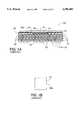
- FIG. 1Ais a cross-sectional side view of a ball grid array package 100 with a prior art heat spreader 102 made of a flat sheet of metal.
- Ball grid array 100includes a substrate 104 with insulation layers 106, conductive trace layers 108, and cavity 116.
- An integrated circuit chip 114is positioned in the bottom of cavity 116.
- Bond wires 118make the electrical connections between bond pads (not shown) on integrated circuit chip 114 and a first conductive trace layer 108a on substrate 104.
- the integrated circuit chipis mounted in "flip chip” or "C4" configuration without the use of bond wires 118. Flip-chip mounting of integrated circuits is well known in the art. Therefore, a detailed description of this method is omitted).
- Vias or conductive through holes 122are used to electrically connect conductive trace layer 108a with the other conductive trace layers 108 and solder balls 110. Solder balls 110 are then used to make electrical connection between ball grid array 100 and a next level electrical structure (not shown) such as a printed circuit board.
- encapsulant 120is in liquid form when it is applied in cavity 116. After application, encapsulant 120 is cured and solidifies to form a protective case around integrated circuit chip 114.
- Encapsulant 120is typically an epoxy base resin.
- FIG. 1Bis a plan view of the lower surface 102a of prior art heat spreader 102.
- FIG. 1Cis an perspective side view of prior art heat spreader 102 attached to ball grid array 100.
- lower surface 102a of heat spreader 102is affixed to the upper surface 104a of substrate 104 and the upper surface 120a of encapsulant 120 with adhesive layer 112.
- FIG. 2is a cross-sectional side view of a second prior art ball grid array package 200 with heat spreader 102.
- cavity 216is created by the application of a plastic over-mold 206 which covers sides 208 and partially covers upper surface 204a of substrate 204. Once created, cavity 216 is filled with encapsulant 120 as described above with respect to prior art ball grid array 100. Heat spreader 102 is then applied to upper surface 120a of encapsulant 120 with adhesive layer 112 as also described above.
- the heat generated by integrated circuit chip 114should be conducted as directly as possible from integrated circuit chip 114, through encapsulant 120, to heat spreader 102 which then radiates the heat to the external environment.
- adhesive layer 112represents an additional, and possibly thermally insulative, layer between integrated circuit chip 114 and heat spreader 102. Therefore, with prior art ball grid arrays 100 and 200, heat is not dissipated as efficiently as possible and the electrical performance of integrated circuit chip 114 can suffer. Further, adhesive layer 112 represents additional production cost, both in terms of materials used and the time and equipment necessary apply those materials.
- FIG. 3is a cross-sectional side view of a prior art ball grid array 300 with prior art heat spreader 102 applied directly to upper surface 120a of encapsulant 120.
- FIG. 3shows air bubbles 302 which often form when prior art heat spreader 102 is applied directly to surface 120a of encapsulant 120.
- Air bubbles 302create several problems. First, the air in air bubbles 302 can become a thermally insulative layer between integrated circuit chip 314 and heat spreader 102 (see for example air bubble 302a in FIG. 3). The additional thermal insulation created by air bubbles 302 defeats the purpose of applying heat spreader 102 directly to encapsulant 120 in the first place, i.e., to decrease insulation between integrated circuit chip 314 and heat spreader 102 by eliminating adhesive layer 112 (see FIG. 1A).
- air bubbles 302can form in, or move to, the areas 314 within cavity 316 surrounding bond wires 118.
- bond wires 118lose the support provided by encapsulant 120 and break more easily, causing the integrated circuit to fail.
- contaminantssuch as moisture
- air bubbles 302.contaminants can compromise package integrity and adversely affect the performance and reliability of integrated circuit chip 314.
- the heat generated by integrated circuit chip 314can cause the air trapped in air bubbles 302 to expand. As the air expands, it can put pressure on encapsulant 120 and create stress cracks in the package which further compromise package integrity.
- Air bubbles 302form in encapsulant 120 because prior art heat spreaders 102 are typically a uniform and continuous metal sheet or plate (see FIGS. 1B and 1C). As a result of their uniform structure, when prior art heat spreaders 102 are initially placed directly on surface 120a of encapsulant 120, air between the lower surface 102a of heat spreader 102 and upper surface 120a of encapsulant 120 is forced down into encapsulant 120 (recall that encapsulant 120 is, at this point in the manufacturing process, in liquid form).
- encapsulant 120in its liquid form often prevents air bubbles 302 from escaping to the sides 310 of cavity 116 before encapsulant 120 cures and hardens. As a result, when encapsulant 120 hardens, air bubbles 302 are permanently formed in cavity 116.
- a heat spreaderwhich can be applied directly to the surface of an encapsulant, when the encapsulant is in a liquid state, so that the heat spreader is secured to a surface of encapsulant without the use of adhesives and without forming air bubbles within the encapsulant.
- the method and article of the inventionprovides for an integrated circuit package which includes a heat spreader with one or more open regions integrally formed in the heat spreader material.
- a heat spreadercomprises a thermally conductive plate made of, for example, aluminum, copper, or an equivalent thermally conductive material.
- the heat spreaderis formed in a predetermined shape, usually a substantially square or rectangular shape.
- the heat spreaderhas a first or bottom surface and a second or top surface, opposite the first surface.
- the heat spreaderalso has a predetermined thickness and at least one open region.
- the open regionscan be any shape desired such as: triangular, rectangular, oval, semicircular or square.
- the first surface of the heat spreaderis applied directly (i.e., without the use of an additional adhesive) to a first surface of the encapsulant, while the encapsulant is still in liquid form. As the encapsulant hardens, a fitted bond is formed between the first surface of the heat spreader and the first surface of the encapsulant.
- At least one tabis formed on, or of, the heat spreader material.
- the tabsare formed by stamping or cutting the heat spreader material in the outline of the open region desired while leaving one portion of the outlined material attached to the heat spreader. The outlined material is then bent back and shaped to form a tab.
- the tab portions of this embodimentcan either stand alone and provide more surface area for heat dissipation, or they can be used to secure an additional heat spreader or heat tower to further facilitate the dissipation of heat from the integrated circuit package.
- the open regions of the disclosed heat spreadersprovide the heat spreaders of the invention with several advantages over the prior art.
- the open regions of the heat spreaderdiscourage the formation of air bubbles in the encapsulant because little or no air can be trapped between the heat spreader and the encapsulant surface. Further, any air bubbles that do form in the encapsulant can escape through the open regions of the heat spreader.
- the heat spreader of the inventionwhen placed on the surface of the liquid encapsulant, the encapsulant fills the open regions of the heat spreader and covers the sides of the open regions.
- a form fitting bond between the heat spreader and the upper surface of the encapsulantis created. This form fitting bond provides for more secure attachment of the heat spreader to the surface of the encapsulant than is possible with typical prior art heat spreaders.
- FIG. 1Ais a cross-sectional side view of a ball grid array package with prior art heat spreader.
- FIG. 1Bis a plan view of the lower surface of prior art heat spreader.
- FIG. 1Cis an perspective side view of prior art heat spreader attached to ball grid array.
- FIG. 2is a cross-sectional side view of a second ball grid array package with prior art heat spreader.
- FIG. 3is a cross-sectional side view of a ball grid array with prior art heat spreader applied directly to upper surface of encapsulant.
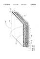
- FIG. 4Ais a plan view of one embodiment of a heat spreader in accordance with the invention.
- FIG. 4Bis a side view thereof.
- FIG. 4Cis a perspective view of the heat spreader of FIG. 4A.
- FIG. 4Dis a side perspective view of the heat spreader positioned on the encapsulant in a cavity of a ball grid array according to the invention.
- FIG. 4Eis a perspective view of a second embodiment of a heat spreader in accordance with the invention.
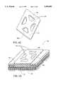
- FIG. 5Ais an plan view of a heat spreader with tabs in accordance with the invention.
- FIG. 5Bis a side view of the heat spreader taken on line 5B--5B of FIG. 5A.
- FIG. 5Cis of side perspective view of the heat spreader positioned on a surface of an encapsulant in a cavity of a ball grid array.
- FIG. 5Dis a side perspective view of a heat spreader with a heat tower partially slid into position within the tabs.
- FIG. 5Eis a side view thereof of FIG. 5D.
- FIG. 5Fis a side view of the heat tower fully positioned and secured within the tabs on the heat spreader.
- FIG. 5Gis a side perspective view of the heat spreader, including the heat tower, bonded to an encapsulant surface of a ball grid array.
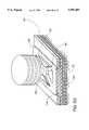
- FIG. 6is a heat spreader attached to a upper surface of an encapsulant in a pin grid array package.
- FIG. 4Ais a plan view of one embodiment of a heat spreader 400 in accordance with the invention.
- Heat spreader 400is formed from a thin (in one embodiment 0.015 inch or 0.381 millimeter thick) thermally conductive plate 412.
- Plate 412may be anodized, copper, or any other thermally conductive material.
- Heat spreader 400can be made to any dimensions desired. However, heat spreader 400 is generally square or rectangular in shape. For example, in one embodiment, heat spreader 400 is a square with a side length 401 of 0.720 inch or 18.29 millimeter and a thickness 402 (see FIG. 4B) of 0.015 inch or 0.381 millimeter. Heat spreader 400 can also be formed with rounded corners 422. Heat spreader 400 includes open regions 403 which are formed by molding, punching or cutting out predetermined portions of heat spreader 400.
- Open regions 403can be any one of numerous shapes including: substantially triangular (as shown in FIG. 4A), substantially square, substantially rectangular, substantially oval, substantially elliptical, or substantially semi-circular.
- FIG. 4Bis a side view of heat spreader 400 showing the first or lower surface 405 of heat spreader 400 which is placed on the first or upper surface 120a of encapsulant 120 (see FIG. 4D), the second or upper surface 407 of heat spreader 400, which is generally exposed to the ambient or outside environment, and the thickness 402.
- the heat spreader 400 shownhas substantially triangular or substantially trapezoidal open regions which open regions are bounded by edges of a central area 400a, edges of peripheral portions 400b of the spreader and edges of a series of four radial arms extending between the central area and the peripheral portions.
- FIG. 4Cis a perspective view of heat spreader 400 showing open regions 403, open region side walls 403a and, first or lower surface 405 of heat spreader 400.
- FIG. 4Dis a side perspective view of heat spreader 400 positioned on first surface 120a of encapsulant 120 in cavity 416 of a ball grid array 450.
- Open regions 403 of heat spreader 400solve the air bubble problem discussed above. This is because air that would be trapped between a continuous surface, such as surface 102a of prior art heat spreader 102 (see FIGS. 1A and 1B) and encapsulant upper surface 120a, can escape through open regions 403 of heat spreader 400. Thus, with heat spreader 400, air is not forced down into encapsulant 120, as it is with prior art heat spreaders 102, to form air bubbles 302 (see FIG. 3). As a result, heat spreader 400 can be applied directly to first surface 120a of encapsulant 120 when encapsulant 120 is in its liquid form (see FIG.
- heat spreader 400eliminates the need for the extra, potentially insulating, adhesive layer 112 between integrated circuit chip 114 and heat spreader 102 (see FIGS. 1A and 1C).
- heat spreader 400provides a secure form fitted bond between first surface 405 of heat spreader 400 and surface 120a of encapsulant 120. This is because heat spreader 400 is placed on surface 120a of encapsulant 120 when encapsulant 120 is in liquid form.
- first surface 405 of heat spreader 400contacts first surface 120a of encapsulant 120
- encapsulant 120in its liquid form, seeps into open regions 403 and covers sides 403a (see FIG. 4C) of open regions 403.
- a fitted bondis created between first surface 120a of encapsulant 120 and first surface 405 of heat spreader 400, including open region sides 403a.
- This form fitted bondis typically stronger than the bond formed between encapsulant surface 120a and the smooth surface 102a of prior art heat spreader 102 (see FIGS. 1B and 1C).
- FIG. 4Eis a perspective view of a second embodiment of a heat spreader in accordance with the invention.
- Heat spreader 400Eis identical to heat spreader 400 except that it includes the additional open area 402E in the center of the heat spreader 400E. Open area 402E provides increased opportunity for air bubbles to escape from encapsulant 120.
- Heat spreader 400Eis just one example of the various other embodiments of heat spreaders which can be created in accordance with the invention that include permutations on the location, position and number of open regions 403.
- FIG. 5Ais an plan view of a heat spreader 500 with tabs 503,505, and 507 in accordance with the invention.
- Heat spreader 500is formed from a thermally conductive plate 512 and is similar to heat spreader 400 of FIG. 4A.
- edge portions 503a, 505a, and 507a of heat spreader 500are not punched or cut out as they were with heat spreader 400. Instead, cuts are made in the general shape of open regions 503c, 505c, and 507c while edge portions 503a, 505a, and 507a, respectively, are left attached to heat spreader 500.
- tab portions 503, 505, and 507are bent outwardly along attached edge portion sides 503a, 505a, and 507a and shaped.
- FIG. 5Btabs 503 and 507 are seen from the side showing one possibility for the general shape of tabs 503, 505, 507. From this perspective tab 505 is seen from the front.
- open region 509 of heat spreader 500is formed by a cutting or punching process as described above with respect to heat spreader 400 and FIG. 4A. Therefore, in one embodiment of the invention, tabs 503, 505, and 507 are formed on only three of the four sides of heat spreader 500. The reason for this particular configuration is described below.
- FIG. 5Cis a side perspective view of heat spreader 500 positioned on surface 120a of encapsulant 120 in cavity 516 of a ball grid array 550.
- heat spreader 500is identical to heat spreader 400 described above and is applied to ball grid array 550 in the same manner as described above with respect to heat spreader 400 and ball grid array 450.
- Tabs 503, 505, and 507can either simply provide additional surface area to dissipate heat away from the integrated circuit package or, in one embodiment of the invention, tabs 503, 505, and 507 are used to secure an supplemental heat spreader or heat tower to further increase the heat dissipation capability of the package.
- FIG. 5Dis a side perspective view of heat spreader 500 with a heat tower 510 partially slid into position within tabs 503, 505, and 507.
- Heat tower 510includes tower 510a, base 512 and stem 514.
- Heat tower 510is removably attached to heat spreader 500 by sliding base 512 of heat tower 510 between tabs 503, 505, and 507.
- FIG. 5Eshows the heat tower 510 partially slid into position on heat spreader 500.
- FIG. 5Fshows the heat tower 510 fully positioned and secured within tabs 503, 505 (not shown in FIG. 5F), and 507 on heat spreader 500.
- FIG. 5Gshows the heat spreader 500, including heat tower 510, bonded to surface 120a of encapsulant 120 of ball grid array 550.
- Heat spreader 500has all the advantages of heat spreader 400 described above, i.e., heat spreader 500 can be attached directly to surface 120a of encapsulant 120 without the use of adhesive layer 112 (see FIG. 1C), or the risk of air bubbles 302 (see FIG. 3) being trapped in encapsulant 120; heat spreader 500 also forms a fitted bond with upper surface 120a of encapsulant 120.
- Heat spreader 500also has several other advantages. For instance, tabs 503, 505, and 507 provide increased heat dissipation surface area and, if still greater heat dissipation capability is desired, tabs 503, 505, and 507 allow a supplementary heat spreader, such heat tower 510, to be quickly fitted to ball grid array 550.
- a supplementary heat spreadersuch heat tower 510
- the size and shape of the supplementary heat spreaders such as heat tower 510, as well as the materials used to make themcan be varied to meet the demands of the customer.
- a manufacturercan custom design integrated circuit packages in a matter of seconds.
- FIG. 6shows heat spreader 500 attached to a upper surface 120a of encapsulant 120 on a pin grid array package 650.
- Pin grid array 650has a structure somewhat similar to ball grid array 550, however, instead of using solder balls 110 (see FIG. 1A) to make the electrical connection between the integrated circuit chip package and a higher level electrical component such as a printed circuit board (not shown), pin grid array 650 uses electrically conductive pins 602.
- the heat spreaders according to the inventioncan be used with virtually any type of integrated circuit package which incorporates protective encapsulant as part of the structure. Furthermore, the heat spreaders of the invention can be manufactured using equipment and production methods already employed in the integrated circuit packaging industry. Therefore, the heat spreaders according to the invention can be mass produced without the investment of prohibitively large amounts of capital.
Landscapes
- Engineering & Computer Science (AREA)
- Physics & Mathematics (AREA)
- Condensed Matter Physics & Semiconductors (AREA)
- General Physics & Mathematics (AREA)
- Computer Hardware Design (AREA)
- Microelectronics & Electronic Packaging (AREA)
- Power Engineering (AREA)
- Chemical & Material Sciences (AREA)
- Materials Engineering (AREA)
- Cooling Or The Like Of Semiconductors Or Solid State Devices (AREA)
Abstract
Description
Claims (8)
Priority Applications (1)
| Application Number | Priority Date | Filing Date | Title |
|---|---|---|---|
| US08/405,462US5596485A (en) | 1995-03-16 | 1995-03-16 | Plastic packaged integrated circuit with heat spreader |
Applications Claiming Priority (1)
| Application Number | Priority Date | Filing Date | Title |
|---|---|---|---|
| US08/405,462US5596485A (en) | 1995-03-16 | 1995-03-16 | Plastic packaged integrated circuit with heat spreader |
Publications (1)
| Publication Number | Publication Date |
|---|---|
| US5596485Atrue US5596485A (en) | 1997-01-21 |
Family
ID=23603795
Family Applications (1)
| Application Number | Title | Priority Date | Filing Date |
|---|---|---|---|
| US08/405,462Expired - LifetimeUS5596485A (en) | 1995-03-16 | 1995-03-16 | Plastic packaged integrated circuit with heat spreader |
Country Status (1)
| Country | Link |
|---|---|
| US (1) | US5596485A (en) |
Cited By (21)
| Publication number | Priority date | Publication date | Assignee | Title |
|---|---|---|---|---|
| US5708564A (en)* | 1996-05-07 | 1998-01-13 | Lin; Andy | Heat sink mounting structure |
| US5898571A (en)* | 1997-04-28 | 1999-04-27 | Lsi Logic Corporation | Apparatus and method for clip-on attachment of heat sinks to encapsulated semiconductor packages |
| US5977622A (en)* | 1997-04-25 | 1999-11-02 | Lsi Logic Corporation | Stiffener with slots for clip-on heat sink attachment |
| US5981314A (en)* | 1996-10-31 | 1999-11-09 | Amkor Technology, Inc. | Near chip size integrated circuit package |
| US6150193A (en)* | 1996-10-31 | 2000-11-21 | Amkor Technology, Inc. | RF shielded device |
| US6386274B1 (en)* | 2001-06-28 | 2002-05-14 | Foxconn Precision Components Co., Ltd. | Heat sink assembly |
| US20020162645A1 (en)* | 2001-02-27 | 2002-11-07 | Chih-Chong Wang | Heatsink assembly having stabilzation plate |
| US20020168798A1 (en)* | 1996-10-31 | 2002-11-14 | Glenn Thomas P. | Method of making near chip size integrated circuit package |
| US6541854B2 (en)* | 2000-12-01 | 2003-04-01 | Siliconware Precision Industries Co., Ltd. | Super low profile package with high efficiency of heat dissipation |
| US20030143781A1 (en)* | 2002-01-31 | 2003-07-31 | Mclellan Neil Robert | Encapsulated integrated circuit package and method of manufacturing an integrated circuit package |
| US20030234454A1 (en)* | 2002-06-24 | 2003-12-25 | Serafin Pedron | Integrated circuit package and method of manufacturing the integrated circuit package |
| US20040046241A1 (en)* | 2002-03-22 | 2004-03-11 | Combs Edward G. | Method of manufacturing enhanced thermal dissipation integrated circuit package |
| US6734552B2 (en) | 2001-07-11 | 2004-05-11 | Asat Limited | Enhanced thermal dissipation integrated circuit package |
| DE10331026B3 (en)* | 2003-07-09 | 2005-02-10 | Ekl Ag | Heat sink element for electronic component has projection of heat-conductive core of heat sink body fitting into opening in base element used for contacting electronic component |
| US7015072B2 (en) | 2001-07-11 | 2006-03-21 | Asat Limited | Method of manufacturing an enhanced thermal dissipation integrated circuit package |
| US20070041158A1 (en)* | 2005-08-16 | 2007-02-22 | Tyco Electronics Corporation | Heat sink fastening system |
| EP1442265A4 (en)* | 2001-10-10 | 2008-01-02 | Aavid Thermalloy Llc | Heat collector with mounting plate |
| EP1709854A4 (en)* | 2003-12-31 | 2010-02-24 | Texas Instruments Inc | System and method for self-leveling heat sink for multiple height devices |
| US20110012257A1 (en)* | 2009-07-14 | 2011-01-20 | Freescale Semiconductor, Inc | Heat spreader for semiconductor package |
| US20130043001A1 (en)* | 2011-08-16 | 2013-02-21 | Hon Hai Precision Industry Co., Ltd. | Heat dissipation device |
| US8643172B2 (en) | 2007-06-08 | 2014-02-04 | Freescale Semiconductor, Inc. | Heat spreader for center gate molding |
Citations (11)
| Publication number | Priority date | Publication date | Assignee | Title |
|---|---|---|---|---|
| US4809053A (en)* | 1986-08-12 | 1989-02-28 | Shinko Electric Industries Co., Ltd. | Semiconductor device and lead frame used therefor |
| JPH03280453A (en)* | 1990-03-29 | 1991-12-11 | Seiko Epson Corp | Semiconductor device and manufacture thereof |
| US5105259A (en)* | 1990-09-28 | 1992-04-14 | Motorola, Inc. | Thermally enhanced semiconductor device utilizing a vacuum to ultimately enhance thermal dissipation |
| JPH05145002A (en)* | 1991-11-25 | 1993-06-11 | Toshiba Corp | Semiconductor device |
| US5225710A (en)* | 1990-07-09 | 1993-07-06 | Lsi Logic Products Gmbh | Highly integrated electronic component with heat-conducting plate |
| US5241133A (en)* | 1990-12-21 | 1993-08-31 | Motorola, Inc. | Leadless pad array chip carrier |
| JPH05267503A (en)* | 1992-03-17 | 1993-10-15 | Yamaha Corp | Semiconductor device |
| US5309320A (en)* | 1991-02-06 | 1994-05-03 | Hughes Aircraft Company | Circuit card assembly conduction converter |
| US5311060A (en)* | 1989-12-19 | 1994-05-10 | Lsi Logic Corporation | Heat sink for semiconductor device assembly |
| US5353193A (en)* | 1993-02-26 | 1994-10-04 | Lsi Logic Corporation | High power dissipating packages with matched heatspreader heatsink assemblies |
| US5367196A (en)* | 1992-09-17 | 1994-11-22 | Olin Corporation | Molded plastic semiconductor package including an aluminum alloy heat spreader |
- 1995
- 1995-03-16USUS08/405,462patent/US5596485A/ennot_activeExpired - Lifetime
Patent Citations (11)
| Publication number | Priority date | Publication date | Assignee | Title |
|---|---|---|---|---|
| US4809053A (en)* | 1986-08-12 | 1989-02-28 | Shinko Electric Industries Co., Ltd. | Semiconductor device and lead frame used therefor |
| US5311060A (en)* | 1989-12-19 | 1994-05-10 | Lsi Logic Corporation | Heat sink for semiconductor device assembly |
| JPH03280453A (en)* | 1990-03-29 | 1991-12-11 | Seiko Epson Corp | Semiconductor device and manufacture thereof |
| US5225710A (en)* | 1990-07-09 | 1993-07-06 | Lsi Logic Products Gmbh | Highly integrated electronic component with heat-conducting plate |
| US5105259A (en)* | 1990-09-28 | 1992-04-14 | Motorola, Inc. | Thermally enhanced semiconductor device utilizing a vacuum to ultimately enhance thermal dissipation |
| US5241133A (en)* | 1990-12-21 | 1993-08-31 | Motorola, Inc. | Leadless pad array chip carrier |
| US5309320A (en)* | 1991-02-06 | 1994-05-03 | Hughes Aircraft Company | Circuit card assembly conduction converter |
| JPH05145002A (en)* | 1991-11-25 | 1993-06-11 | Toshiba Corp | Semiconductor device |
| JPH05267503A (en)* | 1992-03-17 | 1993-10-15 | Yamaha Corp | Semiconductor device |
| US5367196A (en)* | 1992-09-17 | 1994-11-22 | Olin Corporation | Molded plastic semiconductor package including an aluminum alloy heat spreader |
| US5353193A (en)* | 1993-02-26 | 1994-10-04 | Lsi Logic Corporation | High power dissipating packages with matched heatspreader heatsink assemblies |
Cited By (30)
| Publication number | Priority date | Publication date | Assignee | Title |
|---|---|---|---|---|
| US5708564A (en)* | 1996-05-07 | 1998-01-13 | Lin; Andy | Heat sink mounting structure |
| US5981314A (en)* | 1996-10-31 | 1999-11-09 | Amkor Technology, Inc. | Near chip size integrated circuit package |
| US6150193A (en)* | 1996-10-31 | 2000-11-21 | Amkor Technology, Inc. | RF shielded device |
| US6228676B1 (en) | 1996-10-31 | 2001-05-08 | Amkor Technology, Inc. | Near chip size integrated circuit package |
| US6962829B2 (en) | 1996-10-31 | 2005-11-08 | Amkor Technology, Inc. | Method of making near chip size integrated circuit package |
| US20020168798A1 (en)* | 1996-10-31 | 2002-11-14 | Glenn Thomas P. | Method of making near chip size integrated circuit package |
| US5977622A (en)* | 1997-04-25 | 1999-11-02 | Lsi Logic Corporation | Stiffener with slots for clip-on heat sink attachment |
| US5898571A (en)* | 1997-04-28 | 1999-04-27 | Lsi Logic Corporation | Apparatus and method for clip-on attachment of heat sinks to encapsulated semiconductor packages |
| US6713321B2 (en)* | 2000-12-01 | 2004-03-30 | Siliconware Precision Industries Co. Ltd. | Super low profile package with high efficiency of heat dissipation |
| US6541854B2 (en)* | 2000-12-01 | 2003-04-01 | Siliconware Precision Industries Co., Ltd. | Super low profile package with high efficiency of heat dissipation |
| US20030092221A1 (en)* | 2000-12-01 | 2003-05-15 | Chien-Ping Huang | Super low profile package with high efficiency of heat dissipation |
| US20020162645A1 (en)* | 2001-02-27 | 2002-11-07 | Chih-Chong Wang | Heatsink assembly having stabilzation plate |
| US6386274B1 (en)* | 2001-06-28 | 2002-05-14 | Foxconn Precision Components Co., Ltd. | Heat sink assembly |
| US7015072B2 (en) | 2001-07-11 | 2006-03-21 | Asat Limited | Method of manufacturing an enhanced thermal dissipation integrated circuit package |
| US6734552B2 (en) | 2001-07-11 | 2004-05-11 | Asat Limited | Enhanced thermal dissipation integrated circuit package |
| EP1442265A4 (en)* | 2001-10-10 | 2008-01-02 | Aavid Thermalloy Llc | Heat collector with mounting plate |
| US6790710B2 (en) | 2002-01-31 | 2004-09-14 | Asat Limited | Method of manufacturing an integrated circuit package |
| US20030143781A1 (en)* | 2002-01-31 | 2003-07-31 | Mclellan Neil Robert | Encapsulated integrated circuit package and method of manufacturing an integrated circuit package |
| US20050077613A1 (en)* | 2002-01-31 | 2005-04-14 | Mclellan Neil Robert | Integrated circuit package |
| US20040046241A1 (en)* | 2002-03-22 | 2004-03-11 | Combs Edward G. | Method of manufacturing enhanced thermal dissipation integrated circuit package |
| US20030234454A1 (en)* | 2002-06-24 | 2003-12-25 | Serafin Pedron | Integrated circuit package and method of manufacturing the integrated circuit package |
| US6940154B2 (en) | 2002-06-24 | 2005-09-06 | Asat Limited | Integrated circuit package and method of manufacturing the integrated circuit package |
| DE10331026B3 (en)* | 2003-07-09 | 2005-02-10 | Ekl Ag | Heat sink element for electronic component has projection of heat-conductive core of heat sink body fitting into opening in base element used for contacting electronic component |
| EP1709854A4 (en)* | 2003-12-31 | 2010-02-24 | Texas Instruments Inc | System and method for self-leveling heat sink for multiple height devices |
| US20070041158A1 (en)* | 2005-08-16 | 2007-02-22 | Tyco Electronics Corporation | Heat sink fastening system |
| US7362578B2 (en)* | 2005-08-16 | 2008-04-22 | Tyco Electronics Corporation | Heat sink fastening system |
| US8643172B2 (en) | 2007-06-08 | 2014-02-04 | Freescale Semiconductor, Inc. | Heat spreader for center gate molding |
| US20110012257A1 (en)* | 2009-07-14 | 2011-01-20 | Freescale Semiconductor, Inc | Heat spreader for semiconductor package |
| US20130043001A1 (en)* | 2011-08-16 | 2013-02-21 | Hon Hai Precision Industry Co., Ltd. | Heat dissipation device |
| US8807202B2 (en)* | 2011-08-16 | 2014-08-19 | Hong Fu Jin Precision Industry (Shenzhen) Co., Ltd. | Heat dissipation device |
Similar Documents
| Publication | Publication Date | Title |
|---|---|---|
| US5596485A (en) | Plastic packaged integrated circuit with heat spreader | |
| US6404049B1 (en) | Semiconductor device, manufacturing method thereof and mounting board | |
| JP3170182B2 (en) | Resin-sealed semiconductor device and method of manufacturing the same | |
| US6552428B1 (en) | Semiconductor package having an exposed heat spreader | |
| US6246115B1 (en) | Semiconductor package having a heat sink with an exposed surface | |
| TW411595B (en) | Heat structure for semiconductor package device | |
| US7122401B2 (en) | Area array type semiconductor package fabrication method | |
| JP3640557B2 (en) | Lead frame having heat spread and semiconductor package using the lead frame | |
| TWI453838B (en) | No lead package with heat spreader | |
| US5834839A (en) | Preserving clearance between encapsulant and PCB for cavity-down single-tier package assembly | |
| KR100192028B1 (en) | Plastic package type semiconductor device | |
| US7488623B2 (en) | Integrated circuit chip packaging assembly | |
| US5598321A (en) | Ball grid array with heat sink | |
| JPH0217665A (en) | Synthetic resin covered pin-grid-array power package | |
| KR19980058198A (en) | Bottom Lead Semiconductor Package | |
| US6501161B1 (en) | Semiconductor package having increased solder joint strength | |
| US7045883B1 (en) | Thermally enhanced chip scale lead on chip semiconductor package and method of making same | |
| US5789820A (en) | Method for manufacturing heat radiating resin-molded semiconductor device | |
| US6166435A (en) | Flip-chip ball grid array package with a heat slug | |
| US7482679B2 (en) | Leadframe for a semiconductor device | |
| US6875635B2 (en) | Method of attaching a die to a substrate | |
| JP3421137B2 (en) | Bare chip mounting structure and heat sink | |
| CN1319159C (en) | Semiconductor package with heat sink | |
| JP2679806B2 (en) | Resin-sealed pin grid array | |
| KR100431501B1 (en) | High-power package structure for reducing thickness and manufacturing cost thereof and method for fabricating the same |
Legal Events
| Date | Code | Title | Description |
|---|---|---|---|
| STCF | Information on status: patent grant | Free format text:PATENTED CASE | |
| AS | Assignment | Owner name:AMKOR TECHNOLOGY, INC., ARIZONA Free format text:MERGER;ASSIGNOR:AMKOR ELECTRONICS, INC.;REEL/FRAME:009586/0629 Effective date:19980414 | |
| FPAY | Fee payment | Year of fee payment:4 | |
| AS | Assignment | Owner name:GUARDIAN ASSETS, INC., PENNSYLVANIA Free format text:SECURITY INTEREST;ASSIGNOR:AMKOR TECHNOLOGY, INC.;REEL/FRAME:011122/0773 Effective date:20000428 | |
| AS | Assignment | Owner name:SOCIETE GENERALE, NEW YORK Free format text:RE-RECORD TO CORRECT RECEIVING PARTY NAME ON A DOCUMENT PREVIOUSLY RECORDED ON REEL 011122, FRAME 0773.;ASSIGNORS:AMKOR TECHNOLOGY, INC.;GUARDIAN ASSETS, INC.;REEL/FRAME:011457/0702 Effective date:20000428 | |
| AS | Assignment | Owner name:CITICORP USA, INC., NEW YORK Free format text:SECURITY INTEREST;ASSIGNORS:SOCIETE GENERALE;GUARDIAN ASSETS, INC.;REEL/FRAME:011682/0416 Effective date:20010330 | |
| FEPP | Fee payment procedure | Free format text:PAYOR NUMBER ASSIGNED (ORIGINAL EVENT CODE: ASPN); ENTITY STATUS OF PATENT OWNER: LARGE ENTITY | |
| AS | Assignment | Owner name:CITICORP NORTH AMERICA, INC. AS ADMINISTRATIVE AGE Free format text:SECURITY AGREEMENT;ASSIGNORS:AMKOR TECHNOLOGY, INC.;GUARDIAN ASSETS, INC.;REEL/FRAME:014885/0691 Effective date:20040629 | |
| AS | Assignment | Owner name:AMKOR TECHNOLOGY, INC., PENNSYLVANIA Free format text:RELEASE OF LIEN ON PATENTS;ASSIGNOR:CITICORP USA, INC. AS COLLATERAL AGENT;REEL/FRAME:015603/0572 Effective date:20040629 | |
| FPAY | Fee payment | Year of fee payment:8 | |
| AS | Assignment | Owner name:CITICORP NORTH AMERICA, INC. AS "AGENT", NEW YORK Free format text:SECURITY AGREEMENT;ASSIGNORS:AMKOR TECHNOLOGY, INC.;GUARDIAN ASSETS, INC.;REEL/FRAME:015942/0521 Effective date:20041027 | |
| AS | Assignment | Owner name:AMKOR TECHNOLOGY, INC., ARIZONA Free format text:TERMINATION & RELEASE OF PATENT SECURITY AGREEMENT;ASSIGNOR:CITICORP NORTH AMERICA, INC.;REEL/FRAME:017388/0868 Effective date:20051128 Owner name:BANK OF AMERICA, N.A., TEXAS Free format text:SECURITY AGREEMENT;ASSIGNOR:AMKOR TECHNOLOGY, INC.;REEL/FRAME:017379/0630 Effective date:20051123 | |
| FPAY | Fee payment | Year of fee payment:12 | |
| REMI | Maintenance fee reminder mailed | ||
| AS | Assignment | Owner name:BANK OF AMERICA, N.A., AS AGENT, CALIFORNIA Free format text:SECURITY INTEREST;ASSIGNOR:AMKOR TECHNOLOGY, INC.;REEL/FRAME:046683/0139 Effective date:20180713 | |
| AS | Assignment | Owner name:AMKOR TECHNOLOGY SINGAPORE HOLDING PTE.LTD., SINGAPORE Free format text:ASSIGNMENT OF ASSIGNORS INTEREST;ASSIGNOR:AMKOR TECHNOLOGY, INC.;REEL/FRAME:054036/0599 Effective date:20191119 |