US5596451A - Miniature image generator including optics arrangement - Google Patents
Miniature image generator including optics arrangementDownload PDFInfo
- Publication number
- US5596451A US5596451AUS08/380,081US38008195AUS5596451AUS 5596451 AUS5596451 AUS 5596451AUS 38008195 AUS38008195 AUS 38008195AUS 5596451 AUS5596451 AUS 5596451A
- Authority
- US
- United States
- Prior art keywords
- light
- cube
- light modulator
- spatial light
- overall pattern
- Prior art date
- Legal status (The legal status is an assumption and is not a legal conclusion. Google has not performed a legal analysis and makes no representation as to the accuracy of the status listed.)
- Expired - Lifetime
Links
- 238000005286illuminationMethods0.000claimsabstractdescription81
- 230000000007visual effectEffects0.000claimsabstractdescription20
- 239000005262ferroelectric liquid crystals (FLCs)Substances0.000claimsdescription7
- 239000000463materialSubstances0.000claimsdescription6
- 239000011159matrix materialSubstances0.000claimsdescription5
- 239000004973liquid crystal related substanceSubstances0.000claimsdescription3
- 230000003287optical effectEffects0.000description27
- 230000010287polarizationEffects0.000description23
- 238000009125cardiac resynchronization therapyMethods0.000description10
- 230000000712assemblyEffects0.000description5
- 238000000429assemblyMethods0.000description5
- 230000008901benefitEffects0.000description5
- 230000004075alterationEffects0.000description2
- 238000004891communicationMethods0.000description2
- 239000011521glassSubstances0.000description2
- 239000004988Nematic liquid crystalSubstances0.000description1
- 238000013459approachMethods0.000description1
- 239000003086colorantSubstances0.000description1
- 238000013461designMethods0.000description1
- 238000011161developmentMethods0.000description1
- 230000000694effectsEffects0.000description1
- 238000005516engineering processMethods0.000description1
- 238000004519manufacturing processMethods0.000description1
- 239000002991molded plasticSubstances0.000description1
- 238000011160researchMethods0.000description1
- 238000000926separation methodMethods0.000description1
Images


Classifications
- G—PHYSICS
- G02—OPTICS
- G02B—OPTICAL ELEMENTS, SYSTEMS OR APPARATUS
- G02B27/00—Optical systems or apparatus not provided for by any of the groups G02B1/00 - G02B26/00, G02B30/00
- G02B27/01—Head-up displays
- G02B27/017—Head mounted
- G02B27/0172—Head mounted characterised by optical features
- G—PHYSICS
- G02—OPTICS
- G02B—OPTICAL ELEMENTS, SYSTEMS OR APPARATUS
- G02B27/00—Optical systems or apparatus not provided for by any of the groups G02B1/00 - G02B26/00, G02B30/00
- G02B27/01—Head-up displays
- G02B27/0149—Head-up displays characterised by mechanical features
- G02B2027/0154—Head-up displays characterised by mechanical features with movable elements
- G02B2027/0156—Head-up displays characterised by mechanical features with movable elements with optionally usable elements
- G—PHYSICS
- G02—OPTICS
- G02B—OPTICAL ELEMENTS, SYSTEMS OR APPARATUS
- G02B5/00—Optical elements other than lenses
- G02B5/30—Polarising elements
Definitions
- the present inventionrelates generally to image generating systems, and more particularly to optics arrangements especially suitable for miniaturized image generating systems such as the miniaturized image generator disclosed in pending U.S. patent application Ser. No. 08/362,665 Attorney Docket Number DIS1P003 entitled ACTIVE MATRIX LIQUID CRYSTAL IMAGE GENERATOR filed Dec. 22, 1994.
- Miniature image generating systemswhich are small enough to be mounted onto a helmet or small enough to be supported by a pair of eyeglasses will find a wide variety of uses if they can provide adequate resolution and brightness in a small, low-power, and durable pack, age at a low cost.
- Conventional technologiessuch as CRTs are difficult to miniaturize and therefore do not hold much promise for further development in this field.
- new systems based on VLSI integrated circuitsare currently being developed which provide much smaller spatial light modulators for use in a miniaturized image generating systems.
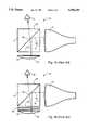
- System 10includes a miniature CRT 12 which produces a desired image.
- a beam splitting cube 14is positioned such that a first external face 16 of cube 14 is located adjacent to the light emitting surface of CRT 12.
- System 10also includes an optical element 18 having a curved light reflecting surface 20 positioned adjacent to a second external face 22 of cube 14. As shown in FIG. 1A, this arrangement results in an overall system which allows a viewer to view the image produced by CRT 12 when the viewer's eye, indicated at 24, is positioned in front of a third external face 26 of cube 14.
- polarizing beam splitting cubeif cube 14 is a polarizer-analyzer beam splitting cube, hereinafter referred to as a polarizing beam splitting cube, internal layer 30 would be a polarizing beam splitting layer which directs light of one polarization, for example S-polarized light, from CRT 12 into optical element 18.
- a quarter wave plate 32is positioned between cube 14 and optical element 18. As described above, curved light reflecting surface 20 of optical element 18 reflects this light back through cube 14.
- quarter wave plate 32changes the polarization of the light directed into optical element 18 such that the light directed back into cube 14 by optical element 18 is the opposite polarization, in this example P-polarized light.
- This P-polarized lightpasses through polarizing beam splitting layer 30 allowing a viewer to view the image produced by CRT 12 when the viewer's eye is positioned in front of external cube face 26.
- the present inventionprovides a variety of novel optics arrangements which, when combined with miniaturized spatial light modulators in novel ways, are capable of providing compact miniaturized image generating systems that may be used to produce a direct view miniature display substantially smaller than the CRT based systems described above.
- the assemblyincludes a spatial light modulator, preferably of the light reflecting type, and an illumination arrangement for providing a particular source of light.
- the spatial light modulatorin its preferred embodiment, has a light-reflecting surface cooperating with a light modulating medium switchable between different states so as to act on light in ways which form an overall pattern of reflected, modulated light, that is a picture at any given instant in time.
- the spatial light modulatoralso has an arrangement for switching the modulating medium between the different states in a controlled way so as to form the overall pattern.
- the overall assemblyfurther includes an optics arrangement having a first member defining a light-reflecting surface configured to direct reflected light into a predetermined area.
- the optics arrangementalso has a second member defining (i) a first external face located in proximity to the illumination arrangement, (ii) a second external face located in proximity to the spatial light modulator, (iii) a third external face located in proximity to the light reflecting surface of the first member, and (iv) a fourth external face.
- the optics arrangementcooperates with the illumination arrangement and the spatial light modulator such that the spatial light modulator forms the overall pattern of light from light provided by the particular source of light and such that the light reflecting surface of the first member directs light provided by the particular source of light from the spatial light modulator into the predetermined area which extends outwardly from the fourth face of the second member.
- This assemblyallows a magnified image of the overall pattern of light formed at and by the spatial light modulator, that is a picture, to be viewed from within the predetermined area.
- the overall pattern of lightserves as the visual display.
- the second memberis a polarizer-analyzer beam splitting cube which defines the first through fourth external faces referred to above.
- the optics arrangementincludes a first member defining a light reflecting surface configured to direct reflected light into a predetermined area.
- the optics arrangementalso includes a second member defining (i) a first external face located in proximity to the illumination means, (ii) a second external face located in proximity to the spatial light modulator, and (iii) a third external face.
- the optics arrangementalso includes a third member defining (i) a first external face immediately adjacent the third face of the second member, (ii) a second external face located in proximity to the light reflecting surface of the first member, and (iii) a third external face in close proximity to the predetermined area into which the first member directs light.
- the second and third membersare both polarizer-analyzer beam splitting cubes.
- FIG. 1Ais a diagrammatic side view of a prior art miniaturized image generating system including a beam splitting cube;
- FIG. 1Bis a diagrammatic side view of a prior art miniaturized image generating system including a polarizing beam splitting cube;
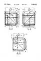
- FIG. 2Ais a diagrammatic side view of a fast configuration of a first embodiment of a miniature image generating system designed in accordance with the present invention
- FIG. 2Bis a diagrammatic side view of a second configuration of a first embodiment of a miniature image generating system designed in accordance with the present invention
- FIG. 2Cis a diagrammatic side view of a second embodiment of a miniature image generating system designed in accordance with the present invention.
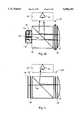
- FIG. 3Ais a diagrammatic side view of a first version of a third embodiment of a miniature image generating system designed in accordance with the present invention.
- FIG. 3Bis a diagrammatic side view of a second version of the third embodiment of a miniature image generating system designed in accordance with the present invention.
- FIG. 3Cis a diagrammatic side view of a third version of the third embodiment of a miniature image generating system designed in accordance with the present invention.
- FIG. 3Dis a diagrammatic side view of a fourth version of a third embodiment of a miniature image generating system designed in accordance with the present invention.
- FIG. 3Eis a diagrammatic side view of a fifth version of a third embodiment of a miniature image generating system designed in accordance with the present invention.
- FIG. 4is a diagrammatic side view of a fourth embodiment of a miniature image generating system designed in accordance with the present invention.
- each assemblyincludes a suitable and readily providable illumination arrangement 34.
- Illumination arrangement 34may be any device or combination of devices that exhibit luminance or may be illumination produced by and optical system that may be focused in proximity to the position occupied by arrangement 34 in the drawings. The purpose of the illuminator is to illuminate the apparent field of view of the image generator.
- Arrangement 34may include, but is not limited to, light sources such as (i) one or more light emitting diodes (LEDs), (ii) laser diodes, (iii) cold cathode or field emitter cathodoluminescent sources, (iv) incandescent and fluorescent lamps together with a switchable color filter such as Displaytech's RGB Fast Filter (a trademark of Displaytech, Inc.) color filter, (v) or a variety of other light sources including novel light source arrangements disclosed in the previously recited pending U.S.
- the assembliesalso include a suitable and readily providable spatial light modulator 36 which is typically and preferably a reflective type light modulator that modulates the light directed into the spatial light modulator by either changing or not changing the polarization of the light depending on the ON/OFF status of each pixel making up the spatial light modulator.
- a suitable and readily providable spatial light modulator 36which is typically and preferably a reflective type light modulator that modulates the light directed into the spatial light modulator by either changing or not changing the polarization of the light depending on the ON/OFF status of each pixel making up the spatial light modulator.
- One preferred novel arrangement for spatial light modulator 36is disclosed and its operation described in detail in the previously recited pending U.S. patent application Ser. No. 08/362,665, Attorney Docket Number DIS1P003.
- the present inventionis not limited to such a spatial light modulator, but instead, would equally apply to spatial light modulators using means other than ferroelectric liquid crystal material as the light modulating medium, for example nematic liquid crystal.
- the assemblies shown in FIGS. 2A-C and 3A-Dalso include an optics arrangement which, as will be described in more detail hereinafter, cooperates with illumination arrangement 34 and spatial light modulator 36 to generate a viewable image.
- This optics arrangementmay take on a variety of specific configurations, some of which are described below for the currently preferred embodiments of the present invention.
- assembly 38includes illumination arrangement 34, spatial light modulator 36, and an optics arrangement 40.
- Optics arrangement 40includes a first member, specifically a mirror 42 having a curved light reflecting surface 44 which is configured to, in cooperation with other members of optics arrangement 40, direct light into a predetermined area 46.
- Optics arrangement 40also includes a second member, which in this embodiment is a polarizer-analyzer beam splitting cube 48, hereinafter referred to as polarizing beam splitting cube 48, having a plurality of external surfaces or faces. As shown in FIG.
- illumination arrangement 34is positioned in proximity to and in optical communication with a first external face 50 of cube 48. If illumination arrangement 34 produces light which is not polarized, an auxiliary polarizer 52 is positioned between illumination arrangement 34 and face 50 of cube 48. Illumination arrangement 34 can be readily removably attached adjacent to face 50 of cube 48 to allow for replacement or repair of this component, as indicated generally at 53. Also, spatial light modulator 36 is positioned in proximity to and in optical communication with a second external face 54 of cube 48 and mirror 42 is positioned in proximity to a third face 56 of cube 48 and a quarter wave plate 58 is positioned between minor 42 and face 56 of cube 48.
- mirror 42 and/or spatial light modulator 36are readily adjustably attached adjacent to face 54 and/or face 56, respectively, as indicated generally at 59.
- This arrangementallows the distance between minor 42 and face 56 of cube 48 and/or the distance between spatial light modulator 36 and face 54 of cube 48 to be adjusted within a predetermined range of distances thereby providing means for focusing the image generated by the assembly.
- Polarizing beam splitting cube 48includes a polarizing beam splitting film or layer 64 positioned within cube 48 such that one side of film 64 faces external faces 50 and 54 of cube 48, and the other side of film 64 faces external face 56 and a fourth external face 66 of cube 48.
- lines 60 and 62which represent light provided by illumination arrangement 34
- light produced by illumination arrangement 34is linearly polarized by auxiliary polarizer 52 such that S-polarized light is directed into film 64 within cube 48.
- fines 60 and 62 and all other fines subsequently used to trace light through the assembliesare illustrative only and are not intended to represent a ray trace as is commonly performed in the course of an optical design.
- S-polarized lightis used in the common manner wherein it specifies that the electric vector of the light incident on a reflective surface is perpendicular to the plane of incidence, in this case the plane of the drawing.
- Spatial light modulator 36is a reflective spatial light modulator having a reflective surface and a light modulating medium, in this case a ferroelectric liquid crystal layer, which is switchable between different states.
- the reflective surface and the modulating mediumcooperate to act on light in ways that form an overall pattern of reflected, modulated light, which constitutes a modulation encoding of a picture which may be viewed.
- the S-polarized light which is directed into spatial light modulator 36is modulated by the ferroelectric liquid crystal material such that the overall pattern of reflected, modulated light is a pattern of light of S-polarized light and P-polarized light which is orthogonally polarized to the S-polarized light.
- the polarizationdepends on the state of the corresponding pixelated portions of the ferroelectric liquid crystal material through which the S-polarized light from illumination arrangement 34 has passed.
- Spatial light modulator 36directs this modulated light back into cube 48 where the light is analyzed by polarizing beam splitting film 64, as will be described immediately below.
- the purpose of analyzing the patternis to decode the polarization modulated pattern and transform it into a brightness modulated pattern which can be viewed and recognized as a display image.
- the S-polarized light from illumination arrangement 34 which spatial light modulator does not change, and therefore remains S-polarized lightis directed back toward illumination arrangement 34.
- the S-polarized light from illumination arrangement 34 which spatial light modulator changes to P-polarized lightpasses through film 64 and is directed toward mirror 42 through quarter wave plate 58.
- Mirror 42reflects light 60 back through quarter wave plate 58 which, since light 60 has passed through quarter wave plate 58 twice, changes light 60 back to S-polarized light.
- polarizing beam splitting film 64directs this S-polarized light out of cube 48 through external face 66 into area 46 which extends outwardly from face 66.
- mirror 42which in this case is a magnifying mirror, is established so as to produce a viewable magnified image of the pattern of modulated light created at and by spatial light modulator 36.
- This imageis viewable when a viewer places an eye within viewing area 46 which extends outward from the fourth face 66 of cube 48 and when the eye is directed generally toward face 66 of the cube.
- This viewable imageis made luminous by light from illumination arrangement 34 as modulated by the polarization control effected by spatial light modulator 36 in cooperation with polarizing beam splitter film 64 and auxiliary polarizer 52, if included.
- This novel arrangementaffords a number of advantageous features.
- the folding of the optical path which extends from the illumination arrangement to the reflective spatial light modulator to the magnifying mirror and thence finally to the viewing areaproduces a compact overall display system.
- the separation between the illumination arrangement and the spatial light modulatorprovides the opportunity to collect the light emitted by the light source with appropriate optical components and to direct a very large proportion of the emitted light through the display components and into the viewing area, thereby producing a bright image via efficient use of light.
- the display of the present inventionis made more suitable for operation from batteries than other displays.
- the various optical components of the display arrangementmay optionally be cemented to the polarizing beam splitting cube to produce a very rugged assembly which cannot become misaligned.
- either the spatial light modulator or the magnifying mirrormust be moveable relative to the other components.
- the above described assemblyforms a real image of illumination arrangement 34 within viewing area 46 and simultaneously forms a virtual image of the pattern of modulated light produced by and at spatial light modulator 36 which is directly visible by a viewer from viewing area 46.
- the real image of illumination arrangement 34is formed within viewing area 46 because illumination arrangement 34 is positioned a distance about twice the focal length of mirror 42 from mirror 42 as discussed in previously recited pending U.S. patent Ser. No. 08/362,234, Attorney Docket Number DIS1P005 which also describes the advantages of this arrangement.
- FIG. 2Ban alternative configuration of the above described embodiment, generally indicated by reference numeral 68, will be described.
- all of the components making up the assemblyare the same as those described above.
- spatial light modulator 36is positioned adjacent to face 66 of cube 48 and the assembly is viewed from viewing area 46 which is now located adjacent to face 54 of cube 48.
- This configurationoperates in a similar manner to the assembly shown in FIG. 2A except as shown by lines 70 and 72, which indicate light provided by illumination arrangement 34, the light from illumination arrangement 34 is directed through cube 48 in a different way.
- lines 70 and 72which indicate light provided by illumination arrangement 34
- auxiliary polarizer 52which allows light of only one polarization, for example P-polarized light, to pass through into cube 48.
- film 64is a polarizing beam splitting film, film 64 allows the vast majority of the P-polarized light to pass through into spatial light modulator 36.
- spatial light modulator 36modulates the light by forming a pattern of S-polarized and P-polarized light which is directed back into cube 48.
- film 64directs the light through quarter wave plate 58 into mirror 42.
- Mirror 42reflects light 70 back through quarter wave plate and into cube 48.
- film 64allows light 70 to pass through into viewing area 46 such that a virtual image of the pattern of modulated light is viewable from viewing area 46.
- film 64allows light 72 to pass through film 64 back toward illumination arrangement 34.
- the present inventionmay be configured in a wide variety of ways with the various components of the assembly being positioned adjacent to various faces of the cube.
- the optics arrangementhas been described as including a polarizing beam splitting cube, this is not a requirement of the present invention.
- Other optical elementssuch as a coated pellicle or glass plate in air, may provide the polarizing beam splitting function and still remain within the scope of the present invention.
- FIG. 2COne alternative to the polarizing beam splitting cube is illustrated in FIG. 2C.
- a second embodiment of the present inventiongenerally designated by reference numeral 74 includes the same components located in the same positions as the assembly of FIG. 2A except that polarizing beam splitting cube 48 is replaced with a non-polarizing beam splitting cube 76. Also, an auxiliary analyzer 78 is positioned adjacent to non-polarizing beam splitting cube 76 between cube 76 and viewing area 46. As shown by line 80 which indicates light provided by illumination arrangement 34, auxiliary polarizer 52 allows light of one polarization, for example S-polarized light, from illumination arrangement 34 to pass into cube 76.
- Beam splitting cube 76includes a beam splitting film 82 positioned within and in this case diagonally through cube 76 with one side facing illumination arrangement 34 and spatial light modulator 36 and the other side facing mirror 42 and viewing area 46.
- Beam splitting film 82directs a first portion of this S-polarized light into spatial light modulator 36 and allows a second portion of the light to pass through cube 76. As shown by dashed line 84, this second portion of light is blocked from passing into viewing area 46 by auxiliary analyzer 78.
- Light 80which is directed into spatial light modulator 36, is modulated forming a pattern of modulated light including S-polarized light and P-polarized light depending on the modulating state of the light modulating medium as described above.
- This modulated lightis directed back into cube 76 and beam splitting film 82 directs a first portion of the modulated light back toward illumination arrangement 34 as indicated by dashed line 86 and allows a second portion of the modulated light to pass though to mirror 42.
- This embodimentdoes not require quarter wave plate 58, however, quarter wave plate 58 may be included depending on which polarization of light from spatial light modulator is chosen to be used to form the magnified image viewable from viewing area 46. In the version of this embodiment shown in FIG. 2C, quarter wave plate 58 is included and therefore reverses the polarization of the pattern of modulated light directed back into cube 76.
- beam splitting film 82allows a first portion of the light from mirror 42 to pass through cube 76, as indicated by dashed line 88, and directs a second portion of the light from mirror 58 into viewing area 46 through auxiliary analyzer 78.
- auxiliary analyzer 78blocks one polarization of light, in this case S-polarized light, and allows the other polarization to pass through to viewing area 46 thereby allowing a magnified image of the pattern of modulated light to be viewed from viewing area 46.
- the assembly of FIG. 2Cdoes not use the light provided by illumination arrangement 34 as efficiently as the assembly shown in FIGS. 2A and 2B, that is, it requires much more light to achieve the same image brightness, the assembly of FIG. 2C does reduce a problem which may occur in the assemblies shown in FIGS. 2A and 2B.
- the assembly of the present inventionis a color version of an image generator which must modulate light of different colors, the polarizing beam splitting cube of FIGS. 2A and 2B is not completely efficient at allowing only light of one polarization to pass through the polarizing beam splitting film.
- the filmcan not be designed to act on light of all wavelengths in the same way, some light of the wrong polarization passes through, or leaks through, the film into viewing area 46 without ever being modulated by spatial light modulator 36.
- some of the S-polarized light of some of the wavelengths of light which is directed into cube 48 from illumination arrangement 34leaks through polarizing beam splitting film 64 and passes directly into viewing area 46. This leakage of light reduces the contrast of the image and degrades the quality of the image or causes a ghosting effect. Therefore, the arrangements shown in FIGS. 2A and 2B are best suited for monochrome systems although they can also be used for a color system.
- the above described assemblies illustrated in FIG. 2A-Cdiffer from the prior art.
- the present inventionutilizes the same optic to illuminate the focal plane and to view the focal plane, whereas the prior art only uses the optic to view the focal plane.
- the present inventionreduces the complexity of the system, resulting in a smaller and more compact arrangement which maximizes the use of the components.
- the components making up the assemblyare small and may be directly attached to the cube, the overall assembly may easily be made very rugged and still light weight.
- many of the componentsmay be molded plastic components for light weight and low cost.
- FIG. 3Aa third embodiment of the present invention generally designated by reference numeral 92 includes many of the same components as described above for FIG. 2A.
- Assembly 92includes illumination arrangement 34, spatial light modulator 36, mirror 42, predetermined area 46, polarizing beam splitting cube 48, and quarter wave plate 58.
- assemble 92further includes an additional polarizing beam splitting cube 94. In this particular configuration of this embodiment and as shown in FIG.
- illumination arrangement 34is positioned adjacent to a first external face 96 of cube 94 and spatial light modulator 36 is positioned adjacent to a second external face 98 of cube 94.
- Cube 94has a third external face 100 which is positioned adjacent external face 54 of cube 48.
- mirror 42 and quarter wave plate 58are positioned adjacent face 56 of cube 48 and viewing area 46 is adjacent face 66 of cube 48.
- lines 102 and 104which represent light provided by illumination arrangement 34, illustrate the operation of assembly 92.
- light from illumination arrangement 34is directed into polarizing beam splitting cube 94 which directs light of one polarization, for example S-polarized light, into spatial light modulator 36 and allows light of the opposite polarization, in this case P-polarized light, to pass through the cube.
- polarizing beam splitting cube 94which directs light of one polarization, for example S-polarized light
- spatial light modulator 36does not change the polarization of the light cube 94 directs this light back toward illumination arrangement 34.
- cube 94allows the P-polarized light to pass into cube 48. As was described above for FIG. 2A, this P-polarized light passes through cube 48 and is directed back into cube 48 by mirror 42 and is changed to S-polarized light by quarter wave plate 58. Polarizing beam splitting cube 48 them directs this S-polarized light in to viewing area 46.
- the extra cube 94is added to the assembly to eliminate the ghosting problem without reducing the efficiency at which the illumination arrangement is utilized.
- any S-polarized light which leaks through cube 94does not pass into viewing area 46 as indicated by dashed line 106, therefore eliminating the ghosting problem.
- FIG. 3BAn additional benefit of the embodiment described immediately above is that adding the second cube allows the various components to be positioned in a wide variety of locations depending on the specific requirements of the application in which the assembly is to be used.
- FIG. 3BOne such variation of this embodiment is illustrated in FIG. 3B and includes a half wave plate 108 positioned between the two cubes.
- the present inventionmay take on a wide variety of specific configurations with the various components being located in a wide variety of positions and mutual orientations and still remain within the scope of the present invention.
- quarter wave plates, half wave plates, mirrors, auxiliary polarizers, auxiliary analyzers, and other conventional optical elementsmay be incorporated in order to configure an assembly designed in accordance with the present invention. The present invention equally applies to all of these variations.
- the cubesbe polarizing beam splitting cubes.
- the added polarizing beam splitting cube 94 of FIG. 3Amay be replaced with a non-polarizing beam splitting cube 110.
- auxiliary polarizer 112is positioned between illumination arrangement 34 and cube 110 and auxiliary analyzer 114 is positioned between cube 110 and cube 48.
- FIGS. 3A-EAnother advantage provided by adding additional cubes as described above for FIGS. 3A-E is that the system may be used as a visual display with see through capability. Since the large cube 48 of each of these systems is transparent, the viewer can see through the display to the external environment while simultaneously viewing the image provided by the spatial light modulator. This see through capability may also be provide for systems using a single cube by modifying the components or rearranging the components as will be described in more detail hereinafter.
- mirror 42is formed as an interior surface within a transparent window 126.
- mirror 42allows the viewer to at least partially see through mirror 42, and, mirror 42 at least partially reflects light from spatial light modulator 36 into viewing area 46.
- System 128includes reflective type spatial light modulator 36, polarizing beam splitting cube 48, mirror 42, quarter wave plate 58, and viewing area 46 as have been described above for previous embodiments.
- system 128includes a transparent light source arrangement 130 which is positioned between spatial light modulator 36 and cube 48.
- a transparent light source arrangementare an edge illuminated holographic optical element or a novel light emitting diode arrangement, both of which are described in detail in previously recited pending U.S. patent Ser. No. 08,362,234, Attorney Docket Number DIS1P005.
- polarized light from transparent light source arrangement 130is directed into spatial light modulator 36 which modulates the light and reflects the light back through transparent light source arrangement 130 into cube 48. From this point, the operation of system 128 is the same as has been described above for other embodiments of the present invention.
- One of the advantages the present invention providesis that the use of a focusing reflecting mirror improves the chromatic aberrations which may be caused by using a more conventional refractive type lens since refractive lenses refract light of different wavelengths in slightly different ways. This is especially true as the assembly is scaled down further and further which is possible using optics arrangements of the present invention and spatial light modulator such as those described in detail in the referenced pending U.S. patent Ser. No. 08/362,665, Attorney Docket Number DIS1P003.
- additional components having optical powermay be included which operate in conjunction with the magnifying minor as a means to determine the position of the viewing region relative to the other parts of the arrangement or to control the field of view, resolution, aberrations or other optical characteristics of the viewable image.
- the function and use of such additional componentsare held to be familiar to those skilled in the art and are therefore to be regarded as falling within the scope of the present invention.
- the present inventionequally applies to all of these variations.
Landscapes
- Physics & Mathematics (AREA)
- General Physics & Mathematics (AREA)
- Optics & Photonics (AREA)
Abstract
Description
Claims (43)
Priority Applications (1)
| Application Number | Priority Date | Filing Date | Title |
|---|---|---|---|
| US08/380,081US5596451A (en) | 1995-01-30 | 1995-01-30 | Miniature image generator including optics arrangement |
Applications Claiming Priority (1)
| Application Number | Priority Date | Filing Date | Title |
|---|---|---|---|
| US08/380,081US5596451A (en) | 1995-01-30 | 1995-01-30 | Miniature image generator including optics arrangement |
Publications (1)
| Publication Number | Publication Date |
|---|---|
| US5596451Atrue US5596451A (en) | 1997-01-21 |
Family
ID=23499825
Family Applications (1)
| Application Number | Title | Priority Date | Filing Date |
|---|---|---|---|
| US08/380,081Expired - LifetimeUS5596451A (en) | 1995-01-30 | 1995-01-30 | Miniature image generator including optics arrangement |
Country Status (1)
| Country | Link |
|---|---|
| US (1) | US5596451A (en) |
Cited By (175)
| Publication number | Priority date | Publication date | Assignee | Title |
|---|---|---|---|---|
| US5734506A (en)* | 1996-08-19 | 1998-03-31 | Delco Electronics Corporation | Head up display projection system having a double reflecting primary mirror |
| US5771124A (en)* | 1996-07-02 | 1998-06-23 | Siliscape | Compact display system with two stage magnification and immersed beam splitter |
| US5838498A (en)* | 1994-12-21 | 1998-11-17 | Siliscape, Inc. | Miniature synthesized virtual image electronic display |
| EP0871054A3 (en)* | 1997-04-07 | 1998-12-23 | International Business Machines Corporation | Miniature displays |
| US5870068A (en)* | 1994-12-21 | 1999-02-09 | Siliscape, Inc. | Twice folded compound magnified virtual image electronic display |
| US5886822A (en)* | 1996-10-08 | 1999-03-23 | The Microoptical Corporation | Image combining system for eyeglasses and face masks |
| US5943171A (en)* | 1998-06-03 | 1999-08-24 | International Business Machines Corporation | Head mounted displays utilizing reflection light valves |
| US5984477A (en)* | 1998-05-22 | 1999-11-16 | Cae Electronics Ltd. | Helmet mounted display with improved SLM illumination |
| US6023372A (en)* | 1997-10-30 | 2000-02-08 | The Microoptical Corporation | Light weight, compact remountable electronic display device for eyeglasses or other head-borne eyewear frames |
| US6073034A (en)* | 1996-10-31 | 2000-06-06 | Kopin Corporation | Wireless telephone display system |
| US6075651A (en)* | 1999-01-28 | 2000-06-13 | Kaiser Electro-Optics, Inc. | Compact collimating apparatus |
| US6091546A (en)* | 1997-10-30 | 2000-07-18 | The Microoptical Corporation | Eyeglass interface system |
| US6204974B1 (en) | 1996-10-08 | 2001-03-20 | The Microoptical Corporation | Compact image display system for eyeglasses or other head-borne frames |
| US6212014B1 (en) | 1997-09-29 | 2001-04-03 | Lsa, Inc. | MWIR polarizing beamsplitter cube and method of making the same |
| US6239908B1 (en) | 1998-11-12 | 2001-05-29 | Shawn L. Kelly | Compact binocular imaging system using a single display |
| US6249269B1 (en) | 1998-04-30 | 2001-06-19 | Agilent Technologies, Inc. | Analog pixel drive circuit for an electro-optical material-based display device |
| US6256151B1 (en) | 2000-06-28 | 2001-07-03 | Agilent Technologies Inc. | Compact microdisplay illumination system |
| US6282029B1 (en) | 2000-05-02 | 2001-08-28 | Agilent Technologies, Inc. | Compact display system |
| US20010017604A1 (en)* | 1996-10-31 | 2001-08-30 | Jeffrey Jacobsen | Reflective microdisplay for portable communication system |
| US6330099B1 (en) | 2000-03-24 | 2001-12-11 | Agilent Technologies, Inc. | Liquid crystal apron and skirt isolation for silicon micro displays |
| US6329974B1 (en) | 1998-04-30 | 2001-12-11 | Agilent Technologies, Inc. | Electro-optical material-based display device having analog pixel drivers |
| US6331916B1 (en)* | 1999-07-14 | 2001-12-18 | Sony Corporation | Virtual image optical system |
| US6333819B1 (en) | 1999-05-26 | 2001-12-25 | Telefonaktiebolaget Lm Ericsson (Publ) | Display for head mounting |
| US20010054989A1 (en)* | 1993-10-22 | 2001-12-27 | Matthew Zavracky | Color sequential display panels |
| US6335838B1 (en)* | 1999-02-23 | 2002-01-01 | Minolta Co., Ltd. | Image display apparatus |
| US6351327B1 (en) | 2000-05-30 | 2002-02-26 | Agilent Technologies, Inc. | Liquid crystal pixel current sensing for silicon micro displays |
| US6353503B1 (en) | 1999-06-21 | 2002-03-05 | The Micropitical Corporation | Eyeglass display lens system employing off-axis optical design |
| US6377402B1 (en) | 2000-06-28 | 2002-04-23 | Agilent Technologies, Inc. | Foldable display system |
| US6404557B2 (en) | 1999-09-10 | 2002-06-11 | Inviso, Inc. | Display illumination system |
| US6421031B1 (en) | 1993-10-22 | 2002-07-16 | Peter A. Ronzani | Camera display system |
| US20020158823A1 (en)* | 1997-10-31 | 2002-10-31 | Matthew Zavracky | Portable microdisplay system |
| WO2002086594A1 (en)* | 2001-04-20 | 2002-10-31 | Martin Shenker Optical Design, Inc. | Compact optic for displaying spatial light modulators |
| US6476784B2 (en) | 1997-10-31 | 2002-11-05 | Kopin Corporation | Portable display system with memory card reader |
| US20030068057A1 (en)* | 2001-10-06 | 2003-04-10 | Miller Eric C. | Information system using eyewear for communication |
| US6552704B2 (en) | 1997-10-31 | 2003-04-22 | Kopin Corporation | Color display with thin gap liquid crystal |
| US20030090439A1 (en)* | 2001-09-07 | 2003-05-15 | Spitzer Mark B. | Light weight, compact, remountable face-supported electronic display |
| US6598976B2 (en) | 2001-09-05 | 2003-07-29 | Optical Products Development Corp. | Method and apparatus for image enhancement and aberration corrections in a small real image projection system, using an off-axis reflector, neutral density window, and an aspheric corrected surface of revolution |
| US20030147145A1 (en)* | 1999-04-27 | 2003-08-07 | Optical Products Development Corporation | Real imaging system with reduced ghost imaging |
| US6618099B1 (en) | 1999-06-21 | 2003-09-09 | The Microoptical Corporation | Display device with eyepiece assembly and display on opto-mechanical support |
| US20030210380A1 (en)* | 1999-04-27 | 2003-11-13 | Optical Products Development Corporation | Image enhancement and aberration corrections in a small real image projection system |
| US6650470B1 (en) | 2002-05-16 | 2003-11-18 | Optical Products Development Corp. | Semi-transparent graphic window for a real imaging system |
| US6690499B1 (en) | 2000-11-22 | 2004-02-10 | Displaytech, Inc. | Multi-state light modulator with non-zero response time and linear gray scale |
| US6724354B1 (en)* | 1999-06-21 | 2004-04-20 | The Microoptical Corporation | Illumination systems for eyeglass and facemask display systems |
| US6733140B2 (en) | 2002-04-19 | 2004-05-11 | Optical Products Development Corp. | Method of ghost reduction and transmission enhancement for a real image projection system |
| US6754632B1 (en) | 2000-09-18 | 2004-06-22 | East Carolina University | Methods and devices for delivering exogenously generated speech signals to enhance fluency in persons who stutter |
| US6785049B1 (en)* | 2000-01-31 | 2004-08-31 | 3M Innovative Properties Company | Illumination system for reflective displays |
| US20050012901A1 (en)* | 2003-07-18 | 2005-01-20 | William Pan | Portable image viewing apparatus |
| US6864861B2 (en) | 1997-12-31 | 2005-03-08 | Brillian Corporation | Image generator having a miniature display device |
| US20050180021A1 (en)* | 2004-02-18 | 2005-08-18 | Interactive Imaging Systems, Inc. | Micro-display engine |
| EP1602942A1 (en)* | 2001-09-04 | 2005-12-07 | Rosemount Aerospace Inc. | A block arrangement of optical elements for a lidar system |
| US7031922B1 (en) | 2000-11-20 | 2006-04-18 | East Carolina University | Methods and devices for enhancing fluency in persons who stutter employing visual speech gestures |
| US7158096B1 (en)* | 1999-06-21 | 2007-01-02 | The Microoptical Corporation | Compact, head-mountable display device with suspended eyepiece assembly |
| EP1798587A1 (en) | 2005-12-15 | 2007-06-20 | Saab Ab | Head-up display |
| US7321354B1 (en) | 1996-10-31 | 2008-01-22 | Kopin Corporation | Microdisplay for portable communication systems |
| US7372447B1 (en) | 1996-10-31 | 2008-05-13 | Kopin Corporation | Microdisplay for portable communication systems |
| US20080219303A1 (en)* | 2007-03-02 | 2008-09-11 | Lucent Technologies Inc. | Color mixing light source and color control data system |
| WO2008156811A1 (en)* | 2007-06-19 | 2008-12-24 | Lucent Technologies Inc. | Compact image projector |
| US20090160737A1 (en)* | 2007-12-21 | 2009-06-25 | Oculon Optoelectronics, Inc. | Head mounted display apparatus |
| US20090184976A1 (en)* | 2008-01-22 | 2009-07-23 | Alcatel-Lucent | System and Method for Color-Compensating a Video Signal Having Reduced Computational Requirements |
| US20090185140A1 (en)* | 2008-01-22 | 2009-07-23 | Lucent Technologies, Inc. | Multi-color light source |
| AU2007203608B2 (en)* | 2001-09-04 | 2009-07-23 | Rosemount Aerospace, Inc. | A block arrangement of optical elements for a Lidar System |
| US20090184659A1 (en)* | 2008-01-22 | 2009-07-23 | Gang Chen | Time division multiplexing a DC-to-DC voltage converter |
| US20090185141A1 (en)* | 2008-01-22 | 2009-07-23 | Lucent Technologies, Inc. | Diffuser configuration for an image projector |
| EP2093603A1 (en) | 2008-02-19 | 2009-08-26 | Saab Ab | Head-up display with brightness control |
| US20100135038A1 (en)* | 2008-11-30 | 2010-06-03 | Handschy Mark A | Frontlights for reflective displays |
| US20100290009A1 (en)* | 2009-05-15 | 2010-11-18 | Alcatel-Lucent Usa Inc. | Image projector employing a speckle-reducing laser source |
| US20110214082A1 (en)* | 2010-02-28 | 2011-09-01 | Osterhout Group, Inc. | Projection triggering through an external marker in an augmented reality eyepiece |
| US20110221658A1 (en)* | 2010-02-28 | 2011-09-15 | Osterhout Group, Inc. | Augmented reality eyepiece with waveguide having a mirrored surface |
| US20110234985A1 (en)* | 2010-03-26 | 2011-09-29 | Alcatel-Lucent Usa Inc. | Despeckling laser-image-projection system |
| US20130088413A1 (en)* | 2011-10-05 | 2013-04-11 | Google Inc. | Method to Autofocus on Near-Eye Display |
| US8456745B2 (en) | 2010-05-12 | 2013-06-04 | Jill Weissman | Compact eyepiece using an imersed field lens |
| US8472120B2 (en) | 2010-02-28 | 2013-06-25 | Osterhout Group, Inc. | See-through near-eye display glasses with a small scale image source |
| US8477425B2 (en) | 2010-02-28 | 2013-07-02 | Osterhout Group, Inc. | See-through near-eye display glasses including a partially reflective, partially transmitting optical element |
| US8482859B2 (en) | 2010-02-28 | 2013-07-09 | Osterhout Group, Inc. | See-through near-eye display glasses wherein image light is transmitted to and reflected from an optically flat film |
| US8488246B2 (en) | 2010-02-28 | 2013-07-16 | Osterhout Group, Inc. | See-through near-eye display glasses including a curved polarizing film in the image source, a partially reflective, partially transmitting optical element and an optically flat film |
| US8570656B1 (en) | 2009-04-06 | 2013-10-29 | Paul Weissman | See-through optical system |
| CN101174028B (en)* | 2004-03-29 | 2015-05-20 | 索尼株式会社 | Optical device and virtual image display device |
| US9091850B2 (en) | 2011-07-20 | 2015-07-28 | Google Inc. | Compact see-through display system |
| US9091851B2 (en) | 2010-02-28 | 2015-07-28 | Microsoft Technology Licensing, Llc | Light control in head mounted displays |
| US9097890B2 (en) | 2010-02-28 | 2015-08-04 | Microsoft Technology Licensing, Llc | Grating in a light transmissive illumination system for see-through near-eye display glasses |
| US9097891B2 (en) | 2010-02-28 | 2015-08-04 | Microsoft Technology Licensing, Llc | See-through near-eye display glasses including an auto-brightness control for the display brightness based on the brightness in the environment |
| US9128281B2 (en) | 2010-09-14 | 2015-09-08 | Microsoft Technology Licensing, Llc | Eyepiece with uniformly illuminated reflective display |
| US9129295B2 (en) | 2010-02-28 | 2015-09-08 | Microsoft Technology Licensing, Llc | See-through near-eye display glasses with a fast response photochromic film system for quick transition from dark to clear |
| US9134534B2 (en) | 2010-02-28 | 2015-09-15 | Microsoft Technology Licensing, Llc | See-through near-eye display glasses including a modular image source |
| US9182596B2 (en) | 2010-02-28 | 2015-11-10 | Microsoft Technology Licensing, Llc | See-through near-eye display glasses with the optical assembly including absorptive polarizers or anti-reflective coatings to reduce stray light |
| US9223134B2 (en) | 2010-02-28 | 2015-12-29 | Microsoft Technology Licensing, Llc | Optical imperfections in a light transmissive illumination system for see-through near-eye display glasses |
| US9229227B2 (en) | 2010-02-28 | 2016-01-05 | Microsoft Technology Licensing, Llc | See-through near-eye display glasses with a light transmissive wedge shaped illumination system |
| US9285589B2 (en) | 2010-02-28 | 2016-03-15 | Microsoft Technology Licensing, Llc | AR glasses with event and sensor triggered control of AR eyepiece applications |
| US20160077335A1 (en)* | 2014-09-16 | 2016-03-17 | Samsung Electronics Co., Ltd. | Optical device for augmented reality |
| WO2016044193A1 (en)* | 2014-09-16 | 2016-03-24 | Microsoft Technology Licensing, Llc | Compact projection light engine for a diffractive waveguide display |
| US9341843B2 (en) | 2010-02-28 | 2016-05-17 | Microsoft Technology Licensing, Llc | See-through near-eye display glasses with a small scale image source |
| US9366862B2 (en) | 2010-02-28 | 2016-06-14 | Microsoft Technology Licensing, Llc | System and method for delivering content to a group of see-through near eye display eyepieces |
| US20160169469A1 (en)* | 2014-12-11 | 2016-06-16 | Stanley Electric Co., Ltd. | Vehicle headlamp unit and vehicle headlamp system |
| US9377623B2 (en) | 2014-08-11 | 2016-06-28 | Microsoft Technology Licensing, Llc | Waveguide eye tracking employing volume Bragg grating |
| US9494799B2 (en) | 2014-09-24 | 2016-11-15 | Microsoft Technology Licensing, Llc | Waveguide eye tracking employing switchable diffraction gratings |
| US9547465B2 (en) | 2014-02-14 | 2017-01-17 | Osterhout Group, Inc. | Object shadowing in head worn computing |
| US9671613B2 (en) | 2014-09-26 | 2017-06-06 | Osterhout Group, Inc. | See-through computer display systems |
| USD792400S1 (en) | 2014-12-31 | 2017-07-18 | Osterhout Group, Inc. | Computer glasses |
| USD794637S1 (en) | 2015-01-05 | 2017-08-15 | Osterhout Group, Inc. | Air mouse |
| US9759917B2 (en) | 2010-02-28 | 2017-09-12 | Microsoft Technology Licensing, Llc | AR glasses with event and sensor triggered AR eyepiece interface to external devices |
| US9798148B2 (en) | 2014-07-08 | 2017-10-24 | Osterhout Group, Inc. | Optical configurations for head-worn see-through displays |
| US9826299B1 (en) | 2016-08-22 | 2017-11-21 | Osterhout Group, Inc. | Speaker systems for head-worn computer systems |
| US9841602B2 (en) | 2014-02-11 | 2017-12-12 | Osterhout Group, Inc. | Location indicating avatar in head worn computing |
| US9843093B2 (en) | 2014-02-11 | 2017-12-12 | Osterhout Group, Inc. | Spatial location presentation in head worn computing |
| US9846308B2 (en) | 2014-01-24 | 2017-12-19 | Osterhout Group, Inc. | Haptic systems for head-worn computers |
| US9852545B2 (en) | 2014-02-11 | 2017-12-26 | Osterhout Group, Inc. | Spatial location presentation in head worn computing |
| US9880441B1 (en) | 2016-09-08 | 2018-01-30 | Osterhout Group, Inc. | Electrochromic systems for head-worn computer systems |
| US20180039065A1 (en)* | 2015-02-16 | 2018-02-08 | Telepathy Japan Inc. | Linearly disposed eyepiece video display |
| US9897822B2 (en) | 2014-04-25 | 2018-02-20 | Osterhout Group, Inc. | Temple and ear horn assembly for headworn computer |
| US9910284B1 (en) | 2016-09-08 | 2018-03-06 | Osterhout Group, Inc. | Optical systems for head-worn computers |
| US20180088448A1 (en)* | 2016-09-26 | 2018-03-29 | Jabil Optics Germany GmbH | Imager and optical sytem with imager |
| US9933622B2 (en) | 2014-01-21 | 2018-04-03 | Osterhout Group, Inc. | See-through computer display systems |
| US9939646B2 (en) | 2014-01-24 | 2018-04-10 | Osterhout Group, Inc. | Stray light suppression for head worn computing |
| US9952664B2 (en) | 2014-01-21 | 2018-04-24 | Osterhout Group, Inc. | Eye imaging in head worn computing |
| US9965681B2 (en) | 2008-12-16 | 2018-05-08 | Osterhout Group, Inc. | Eye imaging in head worn computing |
| US9971156B2 (en) | 2014-01-21 | 2018-05-15 | Osterhout Group, Inc. | See-through computer display systems |
| US10001644B2 (en) | 2014-01-21 | 2018-06-19 | Osterhout Group, Inc. | See-through computer display systems |
| US10007118B2 (en) | 2014-01-21 | 2018-06-26 | Osterhout Group, Inc. | Compact optical system with improved illumination |
| US10018837B2 (en) | 2014-12-03 | 2018-07-10 | Osterhout Group, Inc. | Head worn computer display systems |
| JP2018523157A (en)* | 2015-06-30 | 2018-08-16 | スリーエム イノベイティブ プロパティズ カンパニー | Polarized beam split system |
| US10073266B2 (en) | 2014-01-21 | 2018-09-11 | Osterhout Group, Inc. | See-through computer display systems |
| US10078224B2 (en) | 2014-09-26 | 2018-09-18 | Osterhout Group, Inc. | See-through computer display systems |
| US10101588B2 (en) | 2014-04-25 | 2018-10-16 | Osterhout Group, Inc. | Speaker assembly for headworn computer |
| US10139966B2 (en) | 2015-07-22 | 2018-11-27 | Osterhout Group, Inc. | External user interface for head worn computing |
| US10146772B2 (en) | 2014-04-25 | 2018-12-04 | Osterhout Group, Inc. | Language translation with head-worn computing |
| US10152141B1 (en) | 2017-08-18 | 2018-12-11 | Osterhout Group, Inc. | Controller movement tracking with light emitters |
| CN109116556A (en)* | 2017-06-23 | 2019-01-01 | 芋头科技(杭州)有限公司 | A kind of imaging display system |
| US10180572B2 (en) | 2010-02-28 | 2019-01-15 | Microsoft Technology Licensing, Llc | AR glasses with event and user action control of external applications |
| USD840395S1 (en) | 2016-10-17 | 2019-02-12 | Osterhout Group, Inc. | Head-worn computer |
| US10321821B2 (en) | 2014-01-21 | 2019-06-18 | Mentor Acquisition One, Llc | Eye imaging in head worn computing |
| US10379365B2 (en) | 2014-01-21 | 2019-08-13 | Mentor Acquisition One, Llc | See-through computer display systems |
| US10422995B2 (en) | 2017-07-24 | 2019-09-24 | Mentor Acquisition One, Llc | See-through computer display systems with stray light management |
| USD864959S1 (en) | 2017-01-04 | 2019-10-29 | Mentor Acquisition One, Llc | Computer glasses |
| US10466491B2 (en) | 2016-06-01 | 2019-11-05 | Mentor Acquisition One, Llc | Modular systems for head-worn computers |
| US10466492B2 (en) | 2014-04-25 | 2019-11-05 | Mentor Acquisition One, Llc | Ear horn assembly for headworn computer |
| US10520996B2 (en) | 2014-09-18 | 2019-12-31 | Mentor Acquisition One, Llc | Thermal management for head-worn computer |
| US10539787B2 (en) | 2010-02-28 | 2020-01-21 | Microsoft Technology Licensing, Llc | Head-worn adaptive display |
| US10558420B2 (en) | 2014-02-11 | 2020-02-11 | Mentor Acquisition One, Llc | Spatial location presentation in head worn computing |
| US10578869B2 (en) | 2017-07-24 | 2020-03-03 | Mentor Acquisition One, Llc | See-through computer display systems with adjustable zoom cameras |
| US10591728B2 (en) | 2016-03-02 | 2020-03-17 | Mentor Acquisition One, Llc | Optical systems for head-worn computers |
| US20200142276A1 (en)* | 2018-11-02 | 2020-05-07 | Gary Sharp Innovations, Llc | Compact polarization-based multi-pass optical architectures |
| US10667981B2 (en) | 2016-02-29 | 2020-06-02 | Mentor Acquisition One, Llc | Reading assistance system for visually impaired |
| US10684478B2 (en) | 2016-05-09 | 2020-06-16 | Mentor Acquisition One, Llc | User interface systems for head-worn computers |
| US10684687B2 (en) | 2014-12-03 | 2020-06-16 | Mentor Acquisition One, Llc | See-through computer display systems |
| US10690936B2 (en) | 2016-08-29 | 2020-06-23 | Mentor Acquisition One, Llc | Adjustable nose bridge assembly for headworn computer |
| US10698212B2 (en) | 2014-06-17 | 2020-06-30 | Mentor Acquisition One, Llc | External user interface for head worn computing |
| US10698223B2 (en) | 2014-01-21 | 2020-06-30 | Mentor Acquisition One, Llc | See-through computer display systems |
| US10705339B2 (en) | 2014-01-21 | 2020-07-07 | Mentor Acquisition One, Llc | Suppression of stray light in head worn computing |
| US10739605B2 (en)* | 2015-02-09 | 2020-08-11 | Nokia Technologies Oy | Display apparatus |
| US10824253B2 (en) | 2016-05-09 | 2020-11-03 | Mentor Acquisition One, Llc | User interface systems for head-worn computers |
| US10850116B2 (en) | 2016-12-30 | 2020-12-01 | Mentor Acquisition One, Llc | Head-worn therapy device |
| US10853589B2 (en) | 2014-04-25 | 2020-12-01 | Mentor Acquisition One, Llc | Language translation with head-worn computing |
| US10860100B2 (en) | 2010-02-28 | 2020-12-08 | Microsoft Technology Licensing, Llc | AR glasses with predictive control of external device based on event input |
| US10878775B2 (en) | 2015-02-17 | 2020-12-29 | Mentor Acquisition One, Llc | See-through computer display systems |
| US10877270B2 (en) | 2014-06-05 | 2020-12-29 | Mentor Acquisition One, Llc | Optical configurations for head-worn see-through displays |
| US10908422B2 (en) | 2014-08-12 | 2021-02-02 | Mentor Acquisition One, Llc | Measuring content brightness in head worn computing |
| CN112415738A (en)* | 2020-02-24 | 2021-02-26 | 谷歌有限责任公司 | Programmable injector grid plate |
| US10969584B2 (en) | 2017-08-04 | 2021-04-06 | Mentor Acquisition One, Llc | Image expansion optic for head-worn computer |
| EP3712682A4 (en)* | 2017-12-04 | 2021-06-09 | Huawei Technologies Co., Ltd. | DEVICE, OPTICAL MOTOR COMPONENT AND AUGMENTED REALITY PROCESS |
| US11099380B2 (en) | 2014-01-21 | 2021-08-24 | Mentor Acquisition One, Llc | Eye imaging in head worn computing |
| US11103122B2 (en) | 2014-07-15 | 2021-08-31 | Mentor Acquisition One, Llc | Content presentation in head worn computing |
| US11104272B2 (en) | 2014-03-28 | 2021-08-31 | Mentor Acquisition One, Llc | System for assisted operator safety using an HMD |
| EP3796070A4 (en)* | 2018-09-10 | 2021-09-01 | Matrixed Reality Technology Co., Ltd. | DEVICE OF EXTENDED REALITY AND OPTICAL SYSTEM OF IT |
| US11227294B2 (en) | 2014-04-03 | 2022-01-18 | Mentor Acquisition One, Llc | Sight information collection in head worn computing |
| US11231817B2 (en) | 2014-01-17 | 2022-01-25 | Mentor Acquisition One, Llc | External user interface for head worn computing |
| US11269182B2 (en) | 2014-07-15 | 2022-03-08 | Mentor Acquisition One, Llc | Content presentation in head worn computing |
| US11409105B2 (en) | 2017-07-24 | 2022-08-09 | Mentor Acquisition One, Llc | See-through computer display systems |
| JP2022160457A (en)* | 2016-06-21 | 2022-10-19 | 株式会社Nttドコモ | Lighting device for wearable display |
| US11487110B2 (en) | 2014-01-21 | 2022-11-01 | Mentor Acquisition One, Llc | Eye imaging in head worn computing |
| JP2023520064A (en)* | 2020-03-31 | 2023-05-15 | ▲優▼奈柯恩(北京)科技有限公司 | Optical equipment and head-mounted equipment |
| US11737666B2 (en) | 2014-01-21 | 2023-08-29 | Mentor Acquisition One, Llc | Eye imaging in head worn computing |
| US11851177B2 (en) | 2014-05-06 | 2023-12-26 | Mentor Acquisition One, Llc | Unmanned aerial vehicle launch system |
| US11892644B2 (en) | 2014-01-21 | 2024-02-06 | Mentor Acquisition One, Llc | See-through computer display systems |
| US12105281B2 (en) | 2014-01-21 | 2024-10-01 | Mentor Acquisition One, Llc | See-through computer display systems |
| US12112089B2 (en) | 2014-02-11 | 2024-10-08 | Mentor Acquisition One, Llc | Spatial location presentation in head worn computing |
Citations (4)
| Publication number | Priority date | Publication date | Assignee | Title |
|---|---|---|---|---|
| US4943155A (en)* | 1987-12-22 | 1990-07-24 | Hughes Aircraft Company | Color projection system with a color correction wedge |
| US4969730A (en)* | 1988-10-13 | 1990-11-13 | U.S. Philips Corporation | Image projection arrangement |
| US5164848A (en)* | 1989-11-03 | 1992-11-17 | Gec Marconi Limited | Helmet mounted display |
| US5270804A (en)* | 1990-11-21 | 1993-12-14 | Sextant Avionique | Color display system utilizing optical valves |
- 1995
- 1995-01-30USUS08/380,081patent/US5596451A/ennot_activeExpired - Lifetime
Patent Citations (4)
| Publication number | Priority date | Publication date | Assignee | Title |
|---|---|---|---|---|
| US4943155A (en)* | 1987-12-22 | 1990-07-24 | Hughes Aircraft Company | Color projection system with a color correction wedge |
| US4969730A (en)* | 1988-10-13 | 1990-11-13 | U.S. Philips Corporation | Image projection arrangement |
| US5164848A (en)* | 1989-11-03 | 1992-11-17 | Gec Marconi Limited | Helmet mounted display |
| US5270804A (en)* | 1990-11-21 | 1993-12-14 | Sextant Avionique | Color display system utilizing optical valves |
Cited By (356)
| Publication number | Priority date | Publication date | Assignee | Title |
|---|---|---|---|---|
| US6421031B1 (en) | 1993-10-22 | 2002-07-16 | Peter A. Ronzani | Camera display system |
| US20010054989A1 (en)* | 1993-10-22 | 2001-12-27 | Matthew Zavracky | Color sequential display panels |
| US6683584B2 (en) | 1993-10-22 | 2004-01-27 | Kopin Corporation | Camera display system |
| US5838498A (en)* | 1994-12-21 | 1998-11-17 | Siliscape, Inc. | Miniature synthesized virtual image electronic display |
| US5870068A (en)* | 1994-12-21 | 1999-02-09 | Siliscape, Inc. | Twice folded compound magnified virtual image electronic display |
| US6603443B1 (en) | 1994-12-21 | 2003-08-05 | Three-Five Systems, Inc. | Compact display system controlled by eye position sensory system |
| US5905478A (en)* | 1994-12-21 | 1999-05-18 | Siliscape, Inc. | Twice folded compound magnified virtual image electronic display |
| US5973845A (en)* | 1994-12-21 | 1999-10-26 | Hildebrand; Alfred P. | Miniature synthesized virtual image electronic display |
| US5771124A (en)* | 1996-07-02 | 1998-06-23 | Siliscape | Compact display system with two stage magnification and immersed beam splitter |
| US6433935B2 (en) | 1996-07-02 | 2002-08-13 | Three-Five Systems, Inc. | Display illumination system |
| US5734506A (en)* | 1996-08-19 | 1998-03-31 | Delco Electronics Corporation | Head up display projection system having a double reflecting primary mirror |
| US5886822A (en)* | 1996-10-08 | 1999-03-23 | The Microoptical Corporation | Image combining system for eyeglasses and face masks |
| US6384982B1 (en) | 1996-10-08 | 2002-05-07 | The Microoptical Corporation | Compact image display system for eyeglasses or other head-borne frames |
| US6204974B1 (en) | 1996-10-08 | 2001-03-20 | The Microoptical Corporation | Compact image display system for eyeglasses or other head-borne frames |
| US6356392B1 (en) | 1996-10-08 | 2002-03-12 | The Microoptical Corporation | Compact image display system for eyeglasses or other head-borne frames |
| US6073034A (en)* | 1996-10-31 | 2000-06-06 | Kopin Corporation | Wireless telephone display system |
| US6232937B1 (en) | 1996-10-31 | 2001-05-15 | Kopin Corporation | Low power active display system |
| US6677936B2 (en) | 1996-10-31 | 2004-01-13 | Kopin Corporation | Color display system for a camera |
| US7321354B1 (en) | 1996-10-31 | 2008-01-22 | Kopin Corporation | Microdisplay for portable communication systems |
| US6486862B1 (en) | 1996-10-31 | 2002-11-26 | Kopin Corporation | Card reader display system |
| US7372447B1 (en) | 1996-10-31 | 2008-05-13 | Kopin Corporation | Microdisplay for portable communication systems |
| US20010017604A1 (en)* | 1996-10-31 | 2001-08-30 | Jeffrey Jacobsen | Reflective microdisplay for portable communication system |
| US6310713B2 (en) | 1997-04-07 | 2001-10-30 | International Business Machines Corporation | Optical system for miniature personal displays using reflective light valves |
| EP0871054A3 (en)* | 1997-04-07 | 1998-12-23 | International Business Machines Corporation | Miniature displays |
| US6212014B1 (en) | 1997-09-29 | 2001-04-03 | Lsa, Inc. | MWIR polarizing beamsplitter cube and method of making the same |
| US6091546A (en)* | 1997-10-30 | 2000-07-18 | The Microoptical Corporation | Eyeglass interface system |
| US6023372A (en)* | 1997-10-30 | 2000-02-08 | The Microoptical Corporation | Light weight, compact remountable electronic display device for eyeglasses or other head-borne eyewear frames |
| US6349001B1 (en) | 1997-10-30 | 2002-02-19 | The Microoptical Corporation | Eyeglass interface system |
| US20020158823A1 (en)* | 1997-10-31 | 2002-10-31 | Matthew Zavracky | Portable microdisplay system |
| US7242383B2 (en) | 1997-10-31 | 2007-07-10 | Kopin Corporation | Portable microdisplay system |
| US6552704B2 (en) | 1997-10-31 | 2003-04-22 | Kopin Corporation | Color display with thin gap liquid crystal |
| US6476784B2 (en) | 1997-10-31 | 2002-11-05 | Kopin Corporation | Portable display system with memory card reader |
| US6909419B2 (en) | 1997-10-31 | 2005-06-21 | Kopin Corporation | Portable microdisplay system |
| US6864861B2 (en) | 1997-12-31 | 2005-03-08 | Brillian Corporation | Image generator having a miniature display device |
| US6795064B2 (en) | 1998-04-30 | 2004-09-21 | Agilent Technologies, Inc. | Electro-optical material-based grey scale generating method |
| US6249269B1 (en) | 1998-04-30 | 2001-06-19 | Agilent Technologies, Inc. | Analog pixel drive circuit for an electro-optical material-based display device |
| US6329974B1 (en) | 1998-04-30 | 2001-12-11 | Agilent Technologies, Inc. | Electro-optical material-based display device having analog pixel drivers |
| US5984477A (en)* | 1998-05-22 | 1999-11-16 | Cae Electronics Ltd. | Helmet mounted display with improved SLM illumination |
| US5943171A (en)* | 1998-06-03 | 1999-08-24 | International Business Machines Corporation | Head mounted displays utilizing reflection light valves |
| US6239908B1 (en) | 1998-11-12 | 2001-05-29 | Shawn L. Kelly | Compact binocular imaging system using a single display |
| US6075651A (en)* | 1999-01-28 | 2000-06-13 | Kaiser Electro-Optics, Inc. | Compact collimating apparatus |
| US6335838B1 (en)* | 1999-02-23 | 2002-01-01 | Minolta Co., Ltd. | Image display apparatus |
| US6798579B2 (en) | 1999-04-27 | 2004-09-28 | Optical Products Development Corp. | Real imaging system with reduced ghost imaging |
| US20030210380A1 (en)* | 1999-04-27 | 2003-11-13 | Optical Products Development Corporation | Image enhancement and aberration corrections in a small real image projection system |
| US6935747B2 (en) | 1999-04-27 | 2005-08-30 | Optical Products Development | Image enhancement and aberration corrections in a small real image projection system |
| US20030147145A1 (en)* | 1999-04-27 | 2003-08-07 | Optical Products Development Corporation | Real imaging system with reduced ghost imaging |
| US6333819B1 (en) | 1999-05-26 | 2001-12-25 | Telefonaktiebolaget Lm Ericsson (Publ) | Display for head mounting |
| US6618099B1 (en) | 1999-06-21 | 2003-09-09 | The Microoptical Corporation | Display device with eyepiece assembly and display on opto-mechanical support |
| US6353503B1 (en) | 1999-06-21 | 2002-03-05 | The Micropitical Corporation | Eyeglass display lens system employing off-axis optical design |
| US7158096B1 (en)* | 1999-06-21 | 2007-01-02 | The Microoptical Corporation | Compact, head-mountable display device with suspended eyepiece assembly |
| US6724354B1 (en)* | 1999-06-21 | 2004-04-20 | The Microoptical Corporation | Illumination systems for eyeglass and facemask display systems |
| EP1069451A3 (en)* | 1999-07-14 | 2002-08-21 | Sony Corporation | Virtual image optical system |
| US6331916B1 (en)* | 1999-07-14 | 2001-12-18 | Sony Corporation | Virtual image optical system |
| US6404557B2 (en) | 1999-09-10 | 2002-06-11 | Inviso, Inc. | Display illumination system |
| US20050002097A1 (en)* | 2000-01-31 | 2005-01-06 | 3M Innovative Properties Company | Illumination system for reflective displays |
| US7057814B2 (en) | 2000-01-31 | 2006-06-06 | 3M Innovative Properties Company | Illumination system for reflective displays |
| US20050185277A1 (en)* | 2000-01-31 | 2005-08-25 | 3M Innovative Properties Company | Illumination system for reflective displays |
| US6900936B2 (en) | 2000-01-31 | 2005-05-31 | 3M Innovative Properties Company | Illumination system for reflective displays |
| US6785049B1 (en)* | 2000-01-31 | 2004-08-31 | 3M Innovative Properties Company | Illumination system for reflective displays |
| US6330099B1 (en) | 2000-03-24 | 2001-12-11 | Agilent Technologies, Inc. | Liquid crystal apron and skirt isolation for silicon micro displays |
| US6282029B1 (en) | 2000-05-02 | 2001-08-28 | Agilent Technologies, Inc. | Compact display system |
| US6351327B1 (en) | 2000-05-30 | 2002-02-26 | Agilent Technologies, Inc. | Liquid crystal pixel current sensing for silicon micro displays |
| US6377402B1 (en) | 2000-06-28 | 2002-04-23 | Agilent Technologies, Inc. | Foldable display system |
| US6256151B1 (en) | 2000-06-28 | 2001-07-03 | Agilent Technologies Inc. | Compact microdisplay illumination system |
| US6754632B1 (en) | 2000-09-18 | 2004-06-22 | East Carolina University | Methods and devices for delivering exogenously generated speech signals to enhance fluency in persons who stutter |
| US7031922B1 (en) | 2000-11-20 | 2006-04-18 | East Carolina University | Methods and devices for enhancing fluency in persons who stutter employing visual speech gestures |
| US6690499B1 (en) | 2000-11-22 | 2004-02-10 | Displaytech, Inc. | Multi-state light modulator with non-zero response time and linear gray scale |
| WO2002086594A1 (en)* | 2001-04-20 | 2002-10-31 | Martin Shenker Optical Design, Inc. | Compact optic for displaying spatial light modulators |
| JP2008134257A (en)* | 2001-09-04 | 2008-06-12 | Rosemount Aerospace Inc | Block optical element constitution for lidar |
| EP1602942A1 (en)* | 2001-09-04 | 2005-12-07 | Rosemount Aerospace Inc. | A block arrangement of optical elements for a lidar system |
| AU2007203608B2 (en)* | 2001-09-04 | 2009-07-23 | Rosemount Aerospace, Inc. | A block arrangement of optical elements for a Lidar System |
| US6598976B2 (en) | 2001-09-05 | 2003-07-29 | Optical Products Development Corp. | Method and apparatus for image enhancement and aberration corrections in a small real image projection system, using an off-axis reflector, neutral density window, and an aspheric corrected surface of revolution |
| US20030090439A1 (en)* | 2001-09-07 | 2003-05-15 | Spitzer Mark B. | Light weight, compact, remountable face-supported electronic display |
| US7313246B2 (en) | 2001-10-06 | 2007-12-25 | Stryker Corporation | Information system using eyewear for communication |
| US20030068057A1 (en)* | 2001-10-06 | 2003-04-10 | Miller Eric C. | Information system using eyewear for communication |
| US6733140B2 (en) | 2002-04-19 | 2004-05-11 | Optical Products Development Corp. | Method of ghost reduction and transmission enhancement for a real image projection system |
| US6650470B1 (en) | 2002-05-16 | 2003-11-18 | Optical Products Development Corp. | Semi-transparent graphic window for a real imaging system |
| US20050012901A1 (en)* | 2003-07-18 | 2005-01-20 | William Pan | Portable image viewing apparatus |
| US20050180021A1 (en)* | 2004-02-18 | 2005-08-18 | Interactive Imaging Systems, Inc. | Micro-display engine |
| US7133207B2 (en) | 2004-02-18 | 2006-11-07 | Icuiti Corporation | Micro-display engine |
| US7397607B2 (en) | 2004-02-18 | 2008-07-08 | Vuzix Corporation | Micro-display engine |
| US20070081256A1 (en)* | 2004-02-18 | 2007-04-12 | Icuiti Corporation | Micro-Display Engine |
| CN101174028B (en)* | 2004-03-29 | 2015-05-20 | 索尼株式会社 | Optical device and virtual image display device |
| US20070217018A1 (en)* | 2005-12-15 | 2007-09-20 | Saab Ab | Head-up display |
| US7391574B2 (en) | 2005-12-15 | 2008-06-24 | Saab Ab | Head-up display |
| EP1798587A1 (en) | 2005-12-15 | 2007-06-20 | Saab Ab | Head-up display |
| US20080219303A1 (en)* | 2007-03-02 | 2008-09-11 | Lucent Technologies Inc. | Color mixing light source and color control data system |
| US20090009719A1 (en)* | 2007-06-19 | 2009-01-08 | Lucent Technologies Inc. | Compact image projector |
| US7750286B2 (en) | 2007-06-19 | 2010-07-06 | Alcatel-Lucent Usa Inc. | Compact image projector having a mirror for reflecting a beam received from a polarization beam splitter back to the polarization beam splitter |
| WO2008156811A1 (en)* | 2007-06-19 | 2008-12-24 | Lucent Technologies Inc. | Compact image projector |
| US20090160737A1 (en)* | 2007-12-21 | 2009-06-25 | Oculon Optoelectronics, Inc. | Head mounted display apparatus |
| US11506912B2 (en) | 2008-01-02 | 2022-11-22 | Mentor Acquisition One, Llc | Temple and ear horn assembly for headworn computer |
| US20090184976A1 (en)* | 2008-01-22 | 2009-07-23 | Alcatel-Lucent | System and Method for Color-Compensating a Video Signal Having Reduced Computational Requirements |
| US20090185140A1 (en)* | 2008-01-22 | 2009-07-23 | Lucent Technologies, Inc. | Multi-color light source |
| US20090185141A1 (en)* | 2008-01-22 | 2009-07-23 | Lucent Technologies, Inc. | Diffuser configuration for an image projector |
| US8109638B2 (en) | 2008-01-22 | 2012-02-07 | Alcatel Lucent | Diffuser configuration for an image projector |
| US20090184659A1 (en)* | 2008-01-22 | 2009-07-23 | Gang Chen | Time division multiplexing a DC-to-DC voltage converter |
| US8247999B2 (en) | 2008-01-22 | 2012-08-21 | Alcatel Lucent | Time division multiplexing a DC-to-DC voltage converter |
| US8129669B2 (en) | 2008-01-22 | 2012-03-06 | Alcatel Lucent | System and method generating multi-color light for image display having a controller for temporally interleaving the first and second time intervals of directed first and second light beams |
| US20090213037A1 (en)* | 2008-02-19 | 2009-08-27 | Saab Ab | Head-up display with brightness control |
| US9069163B2 (en) | 2008-02-19 | 2015-06-30 | Saab Ab | Head-up display with brightness control |
| EP2093603A1 (en) | 2008-02-19 | 2009-08-26 | Saab Ab | Head-up display with brightness control |
| US20100135038A1 (en)* | 2008-11-30 | 2010-06-03 | Handschy Mark A | Frontlights for reflective displays |
| US9965681B2 (en) | 2008-12-16 | 2018-05-08 | Osterhout Group, Inc. | Eye imaging in head worn computing |
| US8570656B1 (en) | 2009-04-06 | 2013-10-29 | Paul Weissman | See-through optical system |
| US20100290009A1 (en)* | 2009-05-15 | 2010-11-18 | Alcatel-Lucent Usa Inc. | Image projector employing a speckle-reducing laser source |
| US8226241B2 (en) | 2009-05-15 | 2012-07-24 | Alcatel Lucent | Image projector employing a speckle-reducing laser source |
| US9091851B2 (en) | 2010-02-28 | 2015-07-28 | Microsoft Technology Licensing, Llc | Light control in head mounted displays |
| US10539787B2 (en) | 2010-02-28 | 2020-01-21 | Microsoft Technology Licensing, Llc | Head-worn adaptive display |
| US20110227820A1 (en)* | 2010-02-28 | 2011-09-22 | Osterhout Group, Inc. | Lock virtual keyboard position in an augmented reality eyepiece |
| US9759917B2 (en) | 2010-02-28 | 2017-09-12 | Microsoft Technology Licensing, Llc | AR glasses with event and sensor triggered AR eyepiece interface to external devices |
| US10860100B2 (en) | 2010-02-28 | 2020-12-08 | Microsoft Technology Licensing, Llc | AR glasses with predictive control of external device based on event input |
| US8472120B2 (en) | 2010-02-28 | 2013-06-25 | Osterhout Group, Inc. | See-through near-eye display glasses with a small scale image source |
| US8477425B2 (en) | 2010-02-28 | 2013-07-02 | Osterhout Group, Inc. | See-through near-eye display glasses including a partially reflective, partially transmitting optical element |
| US8482859B2 (en) | 2010-02-28 | 2013-07-09 | Osterhout Group, Inc. | See-through near-eye display glasses wherein image light is transmitted to and reflected from an optically flat film |
| US8488246B2 (en) | 2010-02-28 | 2013-07-16 | Osterhout Group, Inc. | See-through near-eye display glasses including a curved polarizing film in the image source, a partially reflective, partially transmitting optical element and an optically flat film |
| US20110227813A1 (en)* | 2010-02-28 | 2011-09-22 | Osterhout Group, Inc. | Augmented reality eyepiece with secondary attached optic for surroundings environment vision correction |
| US8814691B2 (en) | 2010-02-28 | 2014-08-26 | Microsoft Corporation | System and method for social networking gaming with an augmented reality |
| US20110227812A1 (en)* | 2010-02-28 | 2011-09-22 | Osterhout Group, Inc. | Head nod detection and control in an augmented reality eyepiece |
| US20110221897A1 (en)* | 2010-02-28 | 2011-09-15 | Osterhout Group, Inc. | Eyepiece with waveguide for rectilinear content display with the long axis approximately horizontal |
| US9875406B2 (en) | 2010-02-28 | 2018-01-23 | Microsoft Technology Licensing, Llc | Adjustable extension for temple arm |
| US10268888B2 (en) | 2010-02-28 | 2019-04-23 | Microsoft Technology Licensing, Llc | Method and apparatus for biometric data capture |
| US9097890B2 (en) | 2010-02-28 | 2015-08-04 | Microsoft Technology Licensing, Llc | Grating in a light transmissive illumination system for see-through near-eye display glasses |
| US9097891B2 (en) | 2010-02-28 | 2015-08-04 | Microsoft Technology Licensing, Llc | See-through near-eye display glasses including an auto-brightness control for the display brightness based on the brightness in the environment |
| US20110214082A1 (en)* | 2010-02-28 | 2011-09-01 | Osterhout Group, Inc. | Projection triggering through an external marker in an augmented reality eyepiece |
| US9129295B2 (en) | 2010-02-28 | 2015-09-08 | Microsoft Technology Licensing, Llc | See-through near-eye display glasses with a fast response photochromic film system for quick transition from dark to clear |
| US9134534B2 (en) | 2010-02-28 | 2015-09-15 | Microsoft Technology Licensing, Llc | See-through near-eye display glasses including a modular image source |
| US9182596B2 (en) | 2010-02-28 | 2015-11-10 | Microsoft Technology Licensing, Llc | See-through near-eye display glasses with the optical assembly including absorptive polarizers or anti-reflective coatings to reduce stray light |
| US9223134B2 (en) | 2010-02-28 | 2015-12-29 | Microsoft Technology Licensing, Llc | Optical imperfections in a light transmissive illumination system for see-through near-eye display glasses |
| US9229227B2 (en) | 2010-02-28 | 2016-01-05 | Microsoft Technology Licensing, Llc | See-through near-eye display glasses with a light transmissive wedge shaped illumination system |
| US9285589B2 (en) | 2010-02-28 | 2016-03-15 | Microsoft Technology Licensing, Llc | AR glasses with event and sensor triggered control of AR eyepiece applications |
| US10180572B2 (en) | 2010-02-28 | 2019-01-15 | Microsoft Technology Licensing, Llc | AR glasses with event and user action control of external applications |
| US20110221658A1 (en)* | 2010-02-28 | 2011-09-15 | Osterhout Group, Inc. | Augmented reality eyepiece with waveguide having a mirrored surface |
| US9329689B2 (en) | 2010-02-28 | 2016-05-03 | Microsoft Technology Licensing, Llc | Method and apparatus for biometric data capture |
| US9341843B2 (en) | 2010-02-28 | 2016-05-17 | Microsoft Technology Licensing, Llc | See-through near-eye display glasses with a small scale image source |
| US9366862B2 (en) | 2010-02-28 | 2016-06-14 | Microsoft Technology Licensing, Llc | System and method for delivering content to a group of see-through near eye display eyepieces |
| US20110221669A1 (en)* | 2010-02-28 | 2011-09-15 | Osterhout Group, Inc. | Gesture control in an augmented reality eyepiece |
| US20110234985A1 (en)* | 2010-03-26 | 2011-09-29 | Alcatel-Lucent Usa Inc. | Despeckling laser-image-projection system |
| US8456745B2 (en) | 2010-05-12 | 2013-06-04 | Jill Weissman | Compact eyepiece using an imersed field lens |
| US9128281B2 (en) | 2010-09-14 | 2015-09-08 | Microsoft Technology Licensing, Llc | Eyepiece with uniformly illuminated reflective display |
| US9091850B2 (en) | 2011-07-20 | 2015-07-28 | Google Inc. | Compact see-through display system |
| US20130088413A1 (en)* | 2011-10-05 | 2013-04-11 | Google Inc. | Method to Autofocus on Near-Eye Display |
| US11231817B2 (en) | 2014-01-17 | 2022-01-25 | Mentor Acquisition One, Llc | External user interface for head worn computing |
| US11622426B2 (en) | 2014-01-21 | 2023-04-04 | Mentor Acquisition One, Llc | See-through computer display systems |
| US10001644B2 (en) | 2014-01-21 | 2018-06-19 | Osterhout Group, Inc. | See-through computer display systems |
| US10866420B2 (en) | 2014-01-21 | 2020-12-15 | Mentor Acquisition One, Llc | See-through computer display systems |
| US10890760B2 (en) | 2014-01-21 | 2021-01-12 | Mentor Acquisition One, Llc | See-through computer display systems |
| US11619820B2 (en) | 2014-01-21 | 2023-04-04 | Mentor Acquisition One, Llc | See-through computer display systems |
| US11892644B2 (en) | 2014-01-21 | 2024-02-06 | Mentor Acquisition One, Llc | See-through computer display systems |
| US10481393B2 (en) | 2014-01-21 | 2019-11-19 | Mentor Acquisition One, Llc | See-through computer display systems |
| US11650416B2 (en) | 2014-01-21 | 2023-05-16 | Mentor Acquisition One, Llc | See-through computer display systems |
| US11487110B2 (en) | 2014-01-21 | 2022-11-01 | Mentor Acquisition One, Llc | Eye imaging in head worn computing |
| US11719934B2 (en) | 2014-01-21 | 2023-08-08 | Mentor Acquisition One, Llc | Suppression of stray light in head worn computing |
| US12204097B2 (en) | 2014-01-21 | 2025-01-21 | Mentor Acquisition One, Llc | Eye imaging in head worn computing |
| US10705339B2 (en) | 2014-01-21 | 2020-07-07 | Mentor Acquisition One, Llc | Suppression of stray light in head worn computing |
| US10698223B2 (en) | 2014-01-21 | 2020-06-30 | Mentor Acquisition One, Llc | See-through computer display systems |
| US11737666B2 (en) | 2014-01-21 | 2023-08-29 | Mentor Acquisition One, Llc | Eye imaging in head worn computing |
| US9933622B2 (en) | 2014-01-21 | 2018-04-03 | Osterhout Group, Inc. | See-through computer display systems |
| US10379365B2 (en) | 2014-01-21 | 2019-08-13 | Mentor Acquisition One, Llc | See-through computer display systems |
| US9952664B2 (en) | 2014-01-21 | 2018-04-24 | Osterhout Group, Inc. | Eye imaging in head worn computing |
| US12386186B2 (en) | 2014-01-21 | 2025-08-12 | Mentor Acquisition One, Llc | See-through computer display systems |
| US9971156B2 (en) | 2014-01-21 | 2018-05-15 | Osterhout Group, Inc. | See-through computer display systems |
| US11103132B2 (en) | 2014-01-21 | 2021-08-31 | Mentor Acquisition One, Llc | Eye imaging in head worn computing |
| US10007118B2 (en) | 2014-01-21 | 2018-06-26 | Osterhout Group, Inc. | Compact optical system with improved illumination |
| US10012840B2 (en) | 2014-01-21 | 2018-07-03 | Osterhout Group, Inc. | See-through computer display systems |
| US10012838B2 (en) | 2014-01-21 | 2018-07-03 | Osterhout Group, Inc. | Compact optical system with improved contrast uniformity |
| US10321821B2 (en) | 2014-01-21 | 2019-06-18 | Mentor Acquisition One, Llc | Eye imaging in head worn computing |
| US11126003B2 (en) | 2014-01-21 | 2021-09-21 | Mentor Acquisition One, Llc | See-through computer display systems |
| US11796805B2 (en) | 2014-01-21 | 2023-10-24 | Mentor Acquisition One, Llc | Eye imaging in head worn computing |
| US10073266B2 (en) | 2014-01-21 | 2018-09-11 | Osterhout Group, Inc. | See-through computer display systems |
| US12108989B2 (en) | 2014-01-21 | 2024-10-08 | Mentor Acquisition One, Llc | Eye imaging in head worn computing |
| US11796799B2 (en) | 2014-01-21 | 2023-10-24 | Mentor Acquisition One, Llc | See-through computer display systems |
| US10222618B2 (en) | 2014-01-21 | 2019-03-05 | Osterhout Group, Inc. | Compact optics with reduced chromatic aberrations |
| US11002961B2 (en) | 2014-01-21 | 2021-05-11 | Mentor Acquisition One, Llc | See-through computer display systems |
| US10139632B2 (en) | 2014-01-21 | 2018-11-27 | Osterhout Group, Inc. | See-through computer display systems |
| US11947126B2 (en) | 2014-01-21 | 2024-04-02 | Mentor Acquisition One, Llc | See-through computer display systems |
| US12105281B2 (en) | 2014-01-21 | 2024-10-01 | Mentor Acquisition One, Llc | See-through computer display systems |
| US10191284B2 (en) | 2014-01-21 | 2019-01-29 | Osterhout Group, Inc. | See-through computer display systems |
| US11099380B2 (en) | 2014-01-21 | 2021-08-24 | Mentor Acquisition One, Llc | Eye imaging in head worn computing |
| US12007571B2 (en) | 2014-01-21 | 2024-06-11 | Mentor Acquisition One, Llc | Suppression of stray light in head worn computing |
| US11782274B2 (en) | 2014-01-24 | 2023-10-10 | Mentor Acquisition One, Llc | Stray light suppression for head worn computing |
| US12066635B2 (en) | 2014-01-24 | 2024-08-20 | Mentor Acquisition One, Llc | Stray light suppression for head worn computing |
| US11822090B2 (en) | 2014-01-24 | 2023-11-21 | Mentor Acquisition One, Llc | Haptic systems for head-worn computers |
| US10558050B2 (en) | 2014-01-24 | 2020-02-11 | Mentor Acquisition One, Llc | Haptic systems for head-worn computers |
| US10578874B2 (en) | 2014-01-24 | 2020-03-03 | Mentor Acquisition One, Llc | Stray light suppression for head worn computing |
| US12158592B2 (en) | 2014-01-24 | 2024-12-03 | Mentor Acquisition One, Llc | Haptic systems for head-worn computers |
| US12326565B2 (en) | 2014-01-24 | 2025-06-10 | Mentor Acquisition One, Llc | Stray light suppression for head worn computing |
| US9939646B2 (en) | 2014-01-24 | 2018-04-10 | Osterhout Group, Inc. | Stray light suppression for head worn computing |
| US9846308B2 (en) | 2014-01-24 | 2017-12-19 | Osterhout Group, Inc. | Haptic systems for head-worn computers |
| US12112089B2 (en) | 2014-02-11 | 2024-10-08 | Mentor Acquisition One, Llc | Spatial location presentation in head worn computing |
| US11599326B2 (en) | 2014-02-11 | 2023-03-07 | Mentor Acquisition One, Llc | Spatial location presentation in head worn computing |
| US9841602B2 (en) | 2014-02-11 | 2017-12-12 | Osterhout Group, Inc. | Location indicating avatar in head worn computing |
| US10558420B2 (en) | 2014-02-11 | 2020-02-11 | Mentor Acquisition One, Llc | Spatial location presentation in head worn computing |
| US9843093B2 (en) | 2014-02-11 | 2017-12-12 | Osterhout Group, Inc. | Spatial location presentation in head worn computing |
| US9852545B2 (en) | 2014-02-11 | 2017-12-26 | Osterhout Group, Inc. | Spatial location presentation in head worn computing |
| US9547465B2 (en) | 2014-02-14 | 2017-01-17 | Osterhout Group, Inc. | Object shadowing in head worn computing |
| US10140079B2 (en) | 2014-02-14 | 2018-11-27 | Osterhout Group, Inc. | Object shadowing in head worn computing |
| US12145505B2 (en) | 2014-03-28 | 2024-11-19 | Mentor Acquisition One, Llc | System for assisted operator safety using an HMD |
| US11104272B2 (en) | 2014-03-28 | 2021-08-31 | Mentor Acquisition One, Llc | System for assisted operator safety using an HMD |
| US11227294B2 (en) | 2014-04-03 | 2022-01-18 | Mentor Acquisition One, Llc | Sight information collection in head worn computing |
| US11474360B2 (en) | 2014-04-25 | 2022-10-18 | Mentor Acquisition One, Llc | Speaker assembly for headworn computer |
| US10853589B2 (en) | 2014-04-25 | 2020-12-01 | Mentor Acquisition One, Llc | Language translation with head-worn computing |
| US10634922B2 (en) | 2014-04-25 | 2020-04-28 | Mentor Acquisition One, Llc | Speaker assembly for headworn computer |
| US11809022B2 (en) | 2014-04-25 | 2023-11-07 | Mentor Acquisition One, Llc | Temple and ear horn assembly for headworn computer |
| US12353841B2 (en) | 2014-04-25 | 2025-07-08 | Mentor Acquisition One, Llc | Language translation with head-worn computing |
| US10466492B2 (en) | 2014-04-25 | 2019-11-05 | Mentor Acquisition One, Llc | Ear horn assembly for headworn computer |
| US10101588B2 (en) | 2014-04-25 | 2018-10-16 | Osterhout Group, Inc. | Speaker assembly for headworn computer |
| US12050884B2 (en) | 2014-04-25 | 2024-07-30 | Mentor Acquisition One, Llc | Language translation with head-worn computing |
| US10146772B2 (en) | 2014-04-25 | 2018-12-04 | Osterhout Group, Inc. | Language translation with head-worn computing |
| US12197043B2 (en) | 2014-04-25 | 2025-01-14 | Mentor Acquisition One, Llc | Temple and ear horn assembly for headworn computer |
| US9897822B2 (en) | 2014-04-25 | 2018-02-20 | Osterhout Group, Inc. | Temple and ear horn assembly for headworn computer |
| US10732434B2 (en) | 2014-04-25 | 2020-08-04 | Mentor Acquisition One, Llc | Temple and ear horn assembly for headworn computer |
| US11727223B2 (en) | 2014-04-25 | 2023-08-15 | Mentor Acquisition One, Llc | Language translation with head-worn computing |
| US12210164B2 (en) | 2014-04-25 | 2025-01-28 | Mentor Acquisition One, Llc | Speaker assembly for headworn computer |
| US11880041B2 (en) | 2014-04-25 | 2024-01-23 | Mentor Acquisition One, Llc | Speaker assembly for headworn computer |
| US11851177B2 (en) | 2014-05-06 | 2023-12-26 | Mentor Acquisition One, Llc | Unmanned aerial vehicle launch system |
| US11402639B2 (en) | 2014-06-05 | 2022-08-02 | Mentor Acquisition One, Llc | Optical configurations for head-worn see-through displays |
| US12174388B2 (en) | 2014-06-05 | 2024-12-24 | Mentor Acquisition One, Llc | Optical configurations for head-worn see-through displays |
| US12436395B2 (en) | 2014-06-05 | 2025-10-07 | Mentor Acquisition One, Llc | Optical configurations for head-worn see-through displays |
| US11960089B2 (en) | 2014-06-05 | 2024-04-16 | Mentor Acquisition One, Llc | Optical configurations for head-worn see-through displays |
| US10877270B2 (en) | 2014-06-05 | 2020-12-29 | Mentor Acquisition One, Llc | Optical configurations for head-worn see-through displays |
| US11294180B2 (en) | 2014-06-17 | 2022-04-05 | Mentor Acquisition One, Llc | External user interface for head worn computing |
| US10698212B2 (en) | 2014-06-17 | 2020-06-30 | Mentor Acquisition One, Llc | External user interface for head worn computing |
| US12174378B2 (en) | 2014-06-17 | 2024-12-24 | Mentor Acquisition One, Llc | External user interface for head worn computing |
| US11054645B2 (en) | 2014-06-17 | 2021-07-06 | Mentor Acquisition One, Llc | External user interface for head worn computing |
| US11789267B2 (en) | 2014-06-17 | 2023-10-17 | Mentor Acquisition One, Llc | External user interface for head worn computing |
| US10775630B2 (en) | 2014-07-08 | 2020-09-15 | Mentor Acquisition One, Llc | Optical configurations for head-worn see-through displays |
| US12242068B2 (en) | 2014-07-08 | 2025-03-04 | Mentor Acquisition One, Llc | Optical configurations for head-worn see-through displays |
| US9798148B2 (en) | 2014-07-08 | 2017-10-24 | Osterhout Group, Inc. | Optical configurations for head-worn see-through displays |
| US11940629B2 (en) | 2014-07-08 | 2024-03-26 | Mentor Acquisition One, Llc | Optical configurations for head-worn see-through displays |
| US11409110B2 (en) | 2014-07-08 | 2022-08-09 | Mentor Acquisition One, Llc | Optical configurations for head-worn see-through displays |
| US10564426B2 (en) | 2014-07-08 | 2020-02-18 | Mentor Acquisition One, Llc | Optical configurations for head-worn see-through displays |
| US12232688B2 (en) | 2014-07-15 | 2025-02-25 | Mentor Acquisition One, Llc | Content presentation in head worn computing |
| US11269182B2 (en) | 2014-07-15 | 2022-03-08 | Mentor Acquisition One, Llc | Content presentation in head worn computing |
| US11103122B2 (en) | 2014-07-15 | 2021-08-31 | Mentor Acquisition One, Llc | Content presentation in head worn computing |
| US11786105B2 (en) | 2014-07-15 | 2023-10-17 | Mentor Acquisition One, Llc | Content presentation in head worn computing |
| US9377623B2 (en) | 2014-08-11 | 2016-06-28 | Microsoft Technology Licensing, Llc | Waveguide eye tracking employing volume Bragg grating |
| US11360314B2 (en) | 2014-08-12 | 2022-06-14 | Mentor Acquisition One, Llc | Measuring content brightness in head worn computing |
| US10908422B2 (en) | 2014-08-12 | 2021-02-02 | Mentor Acquisition One, Llc | Measuring content brightness in head worn computing |
| US11630315B2 (en) | 2014-08-12 | 2023-04-18 | Mentor Acquisition One, Llc | Measuring content brightness in head worn computing |
| US9664903B2 (en)* | 2014-09-16 | 2017-05-30 | Samsung Electronics Co., Ltd. | Optical device for augmented reality |
| WO2016044193A1 (en)* | 2014-09-16 | 2016-03-24 | Microsoft Technology Licensing, Llc | Compact projection light engine for a diffractive waveguide display |
| US20160077335A1 (en)* | 2014-09-16 | 2016-03-17 | Samsung Electronics Co., Ltd. | Optical device for augmented reality |
| US11474575B2 (en) | 2014-09-18 | 2022-10-18 | Mentor Acquisition One, Llc | Thermal management for head-worn computer |
| US10963025B2 (en) | 2014-09-18 | 2021-03-30 | Mentor Acquisition One, Llc | Thermal management for head-worn computer |
| US10520996B2 (en) | 2014-09-18 | 2019-12-31 | Mentor Acquisition One, Llc | Thermal management for head-worn computer |
| US9494799B2 (en) | 2014-09-24 | 2016-11-15 | Microsoft Technology Licensing, Llc | Waveguide eye tracking employing switchable diffraction gratings |
| US9671613B2 (en) | 2014-09-26 | 2017-06-06 | Osterhout Group, Inc. | See-through computer display systems |
| US10078224B2 (en) | 2014-09-26 | 2018-09-18 | Osterhout Group, Inc. | See-through computer display systems |
| US10197801B2 (en) | 2014-12-03 | 2019-02-05 | Osterhout Group, Inc. | Head worn computer display systems |
| US11262846B2 (en) | 2014-12-03 | 2022-03-01 | Mentor Acquisition One, Llc | See-through computer display systems |
| US10684687B2 (en) | 2014-12-03 | 2020-06-16 | Mentor Acquisition One, Llc | See-through computer display systems |
| US10018837B2 (en) | 2014-12-03 | 2018-07-10 | Osterhout Group, Inc. | Head worn computer display systems |
| US11809628B2 (en) | 2014-12-03 | 2023-11-07 | Mentor Acquisition One, Llc | See-through computer display systems |
| US12164693B2 (en) | 2014-12-03 | 2024-12-10 | Mentor Acquisition One, Llc | See-through computer display systems |
| US10036889B2 (en) | 2014-12-03 | 2018-07-31 | Osterhout Group, Inc. | Head worn computer display systems |
| US10174895B2 (en) | 2014-12-11 | 2019-01-08 | Stanley Electric Co., Ltd. | Vehicle headlamp unit and vehicle headlamp system |
| US20160169469A1 (en)* | 2014-12-11 | 2016-06-16 | Stanley Electric Co., Ltd. | Vehicle headlamp unit and vehicle headlamp system |
| US10174894B2 (en)* | 2014-12-11 | 2019-01-08 | Stanley Electric Co., Ltd. | Vehicle headlamp unit and vehicle headlamp system |
| USD792400S1 (en) | 2014-12-31 | 2017-07-18 | Osterhout Group, Inc. | Computer glasses |
| USD794637S1 (en) | 2015-01-05 | 2017-08-15 | Osterhout Group, Inc. | Air mouse |
| US10739605B2 (en)* | 2015-02-09 | 2020-08-11 | Nokia Technologies Oy | Display apparatus |
| US20180039065A1 (en)* | 2015-02-16 | 2018-02-08 | Telepathy Japan Inc. | Linearly disposed eyepiece video display |
| US12142242B2 (en) | 2015-02-17 | 2024-11-12 | Mentor Acquisition One, Llc | See-through computer display systems |
| US10878775B2 (en) | 2015-02-17 | 2020-12-29 | Mentor Acquisition One, Llc | See-through computer display systems |
| US11721303B2 (en) | 2015-02-17 | 2023-08-08 | Mentor Acquisition One, Llc | See-through computer display systems |
| JP2018523157A (en)* | 2015-06-30 | 2018-08-16 | スリーエム イノベイティブ プロパティズ カンパニー | Polarized beam split system |
| US11061233B2 (en) | 2015-06-30 | 2021-07-13 | 3M Innovative Properties Company | Polarizing beam splitter and illuminator including same |
| US11693243B2 (en) | 2015-06-30 | 2023-07-04 | 3M Innovative Properties Company | Polarizing beam splitting system |
| US12271560B2 (en) | 2015-07-22 | 2025-04-08 | Mentor Acquisition One, Llc | External user interface for head worn computing |
| US10139966B2 (en) | 2015-07-22 | 2018-11-27 | Osterhout Group, Inc. | External user interface for head worn computing |
| US11209939B2 (en) | 2015-07-22 | 2021-12-28 | Mentor Acquisition One, Llc | External user interface for head worn computing |
| US11816296B2 (en) | 2015-07-22 | 2023-11-14 | Mentor Acquisition One, Llc | External user interface for head worn computing |
| US10667981B2 (en) | 2016-02-29 | 2020-06-02 | Mentor Acquisition One, Llc | Reading assistance system for visually impaired |
| US12171713B2 (en) | 2016-02-29 | 2024-12-24 | Mentor Acquisition One, Llc | Providing enhanced images for navigation |
| US10849817B2 (en) | 2016-02-29 | 2020-12-01 | Mentor Acquisition One, Llc | Providing enhanced images for navigation |
| US11298288B2 (en) | 2016-02-29 | 2022-04-12 | Mentor Acquisition One, Llc | Providing enhanced images for navigation |
| US11654074B2 (en) | 2016-02-29 | 2023-05-23 | Mentor Acquisition One, Llc | Providing enhanced images for navigation |
| US10591728B2 (en) | 2016-03-02 | 2020-03-17 | Mentor Acquisition One, Llc | Optical systems for head-worn computers |
| US12007562B2 (en) | 2016-03-02 | 2024-06-11 | Mentor Acquisition One, Llc | Optical systems for head-worn computers |
| US11592669B2 (en) | 2016-03-02 | 2023-02-28 | Mentor Acquisition One, Llc | Optical systems for head-worn computers |
| US12405466B2 (en) | 2016-03-02 | 2025-09-02 | Mentor Acquisition One, Llc | Optical systems for head-worn computers |
| US11156834B2 (en) | 2016-03-02 | 2021-10-26 | Mentor Acquisition One, Llc | Optical systems for head-worn computers |
| US11500212B2 (en) | 2016-05-09 | 2022-11-15 | Mentor Acquisition One, Llc | User interface systems for head-worn computers |
| US10824253B2 (en) | 2016-05-09 | 2020-11-03 | Mentor Acquisition One, Llc | User interface systems for head-worn computers |
| US11226691B2 (en) | 2016-05-09 | 2022-01-18 | Mentor Acquisition One, Llc | User interface systems for head-worn computers |
| US12050321B2 (en) | 2016-05-09 | 2024-07-30 | Mentor Acquisition One, Llc | User interface systems for head-worn computers |
| US10684478B2 (en) | 2016-05-09 | 2020-06-16 | Mentor Acquisition One, Llc | User interface systems for head-worn computers |
| US12320982B2 (en) | 2016-05-09 | 2025-06-03 | Mentor Acquisition One, Llc | User interface systems for head-worn computers |
| US11320656B2 (en) | 2016-05-09 | 2022-05-03 | Mentor Acquisition One, Llc | User interface systems for head-worn computers |
| US11460708B2 (en) | 2016-06-01 | 2022-10-04 | Mentor Acquisition One, Llc | Modular systems for head-worn computers |
| US11977238B2 (en) | 2016-06-01 | 2024-05-07 | Mentor Acquisition One, Llc | Modular systems for head-worn computers |
| US12174393B2 (en) | 2016-06-01 | 2024-12-24 | Mentor Acquisition One, Llc | Modular systems for head-worn computers |
| US10466491B2 (en) | 2016-06-01 | 2019-11-05 | Mentor Acquisition One, Llc | Modular systems for head-worn computers |
| US11754845B2 (en) | 2016-06-01 | 2023-09-12 | Mentor Acquisition One, Llc | Modular systems for head-worn computers |
| US11586048B2 (en) | 2016-06-01 | 2023-02-21 | Mentor Acquisition One, Llc | Modular systems for head-worn computers |
| US11022808B2 (en) | 2016-06-01 | 2021-06-01 | Mentor Acquisition One, Llc | Modular systems for head-worn computers |
| JP2022160457A (en)* | 2016-06-21 | 2022-10-19 | 株式会社Nttドコモ | Lighting device for wearable display |
| US10757495B2 (en) | 2016-08-22 | 2020-08-25 | Mentor Acquisition One, Llc | Speaker systems for head-worn computer systems |
| US9826299B1 (en) | 2016-08-22 | 2017-11-21 | Osterhout Group, Inc. | Speaker systems for head-worn computer systems |
| US12120477B2 (en) | 2016-08-22 | 2024-10-15 | Mentor Acquisition One, Llc | Speaker systems for head-worn computer systems |
| US11825257B2 (en) | 2016-08-22 | 2023-11-21 | Mentor Acquisition One, Llc | Speaker systems for head-worn computer systems |
| US11350196B2 (en) | 2016-08-22 | 2022-05-31 | Mentor Acquisition One, Llc | Speaker systems for head-worn computer systems |
| US10690936B2 (en) | 2016-08-29 | 2020-06-23 | Mentor Acquisition One, Llc | Adjustable nose bridge assembly for headworn computer |
| US11409128B2 (en) | 2016-08-29 | 2022-08-09 | Mentor Acquisition One, Llc | Adjustable nose bridge assembly for headworn computer |
| US9910284B1 (en) | 2016-09-08 | 2018-03-06 | Osterhout Group, Inc. | Optical systems for head-worn computers |
| US12111473B2 (en) | 2016-09-08 | 2024-10-08 | Mentor Acquisition One, Llc | Optical systems for head-worn computers |
| US12099280B2 (en) | 2016-09-08 | 2024-09-24 | Mentor Acquisition One, Llc | Electrochromic systems for head-worn computer systems |
| US11415856B2 (en) | 2016-09-08 | 2022-08-16 | Mentor Acquisition One, Llc | Electrochromic systems for head-worn computer systems |
| US10768500B2 (en) | 2016-09-08 | 2020-09-08 | Mentor Acquisition One, Llc | Electrochromic systems for head-worn computer systems |
| US9880441B1 (en) | 2016-09-08 | 2018-01-30 | Osterhout Group, Inc. | Electrochromic systems for head-worn computer systems |
| US10534180B2 (en) | 2016-09-08 | 2020-01-14 | Mentor Acquisition One, Llc | Optical systems for head-worn computers |
| US11366320B2 (en) | 2016-09-08 | 2022-06-21 | Mentor Acquisition One, Llc | Optical systems for head-worn computers |
| US11604358B2 (en) | 2016-09-08 | 2023-03-14 | Mentor Acquisition One, Llc | Optical systems for head-worn computers |
| US11768417B2 (en) | 2016-09-08 | 2023-09-26 | Mentor Acquisition One, Llc | Electrochromic systems for head-worn computer systems |
| US20180088448A1 (en)* | 2016-09-26 | 2018-03-29 | Jabil Optics Germany GmbH | Imager and optical sytem with imager |
| US10809602B2 (en)* | 2016-09-26 | 2020-10-20 | Jabil Optics Germany GmbH | Imager and optical system with imager |
| USD840395S1 (en) | 2016-10-17 | 2019-02-12 | Osterhout Group, Inc. | Head-worn computer |
| US11771915B2 (en) | 2016-12-30 | 2023-10-03 | Mentor Acquisition One, Llc | Head-worn therapy device |
| US10850116B2 (en) | 2016-12-30 | 2020-12-01 | Mentor Acquisition One, Llc | Head-worn therapy device |
| US12337189B2 (en) | 2016-12-30 | 2025-06-24 | Mentor Acquisition One, Llc | Head-worn therapy device |
| USD918905S1 (en) | 2017-01-04 | 2021-05-11 | Mentor Acquisition One, Llc | Computer glasses |
| USD864959S1 (en) | 2017-01-04 | 2019-10-29 | Mentor Acquisition One, Llc | Computer glasses |
| USD947186S1 (en) | 2017-01-04 | 2022-03-29 | Mentor Acquisition One, Llc | Computer glasses |
| CN109116556A (en)* | 2017-06-23 | 2019-01-01 | 芋头科技(杭州)有限公司 | A kind of imaging display system |
| US10578869B2 (en) | 2017-07-24 | 2020-03-03 | Mentor Acquisition One, Llc | See-through computer display systems with adjustable zoom cameras |
| US11550157B2 (en) | 2017-07-24 | 2023-01-10 | Mentor Acquisition One, Llc | See-through computer display systems |
| US11226489B2 (en) | 2017-07-24 | 2022-01-18 | Mentor Acquisition One, Llc | See-through computer display systems with stray light management |
| US12393030B2 (en) | 2017-07-24 | 2025-08-19 | Mentor Acquisition One, Llc | See-through computer display systems with adjustable zoom cameras |
| US11971554B2 (en) | 2017-07-24 | 2024-04-30 | Mentor Acquisition One, Llc | See-through computer display systems with stray light management |
| US11668939B2 (en) | 2017-07-24 | 2023-06-06 | Mentor Acquisition One, Llc | See-through computer display systems with stray light management |
| US11960095B2 (en) | 2017-07-24 | 2024-04-16 | Mentor Acquisition One, Llc | See-through computer display systems |
| US11409105B2 (en) | 2017-07-24 | 2022-08-09 | Mentor Acquisition One, Llc | See-through computer display systems |
| US11042035B2 (en) | 2017-07-24 | 2021-06-22 | Mentor Acquisition One, Llc | See-through computer display systems with adjustable zoom cameras |
| US11789269B2 (en) | 2017-07-24 | 2023-10-17 | Mentor Acquisition One, Llc | See-through computer display systems |
| US10422995B2 (en) | 2017-07-24 | 2019-09-24 | Mentor Acquisition One, Llc | See-through computer display systems with stray light management |
| US12222513B2 (en) | 2017-07-24 | 2025-02-11 | Mentor Acquisition One, Llc | See-through computer display systems with stray light management |
| US11567328B2 (en) | 2017-07-24 | 2023-01-31 | Mentor Acquisition One, Llc | See-through computer display systems with adjustable zoom cameras |
| US11947120B2 (en) | 2017-08-04 | 2024-04-02 | Mentor Acquisition One, Llc | Image expansion optic for head-worn computer |
| US12436392B2 (en) | 2017-08-04 | 2025-10-07 | Mentor Acquisition One, Llc | Image expansion optic for head-worn computer |
| US10969584B2 (en) | 2017-08-04 | 2021-04-06 | Mentor Acquisition One, Llc | Image expansion optic for head-worn computer |
| US11500207B2 (en) | 2017-08-04 | 2022-11-15 | Mentor Acquisition One, Llc | Image expansion optic for head-worn computer |
| US10152141B1 (en) | 2017-08-18 | 2018-12-11 | Osterhout Group, Inc. | Controller movement tracking with light emitters |
| US11947735B2 (en) | 2017-08-18 | 2024-04-02 | Mentor Acquisition One, Llc | Controller movement tracking with light emitters |
| US11474619B2 (en) | 2017-08-18 | 2022-10-18 | Mentor Acquisition One, Llc | Controller movement tracking with light emitters |
| US11079858B2 (en) | 2017-08-18 | 2021-08-03 | Mentor Acquisition One, Llc | Controller movement tracking with light emitters |
| US11269186B2 (en) | 2017-12-04 | 2022-03-08 | Huawei Technologies Co., Ltd. | Augmented reality apparatus and method, and optical engine component |
| EP3712682A4 (en)* | 2017-12-04 | 2021-06-09 | Huawei Technologies Co., Ltd. | DEVICE, OPTICAL MOTOR COMPONENT AND AUGMENTED REALITY PROCESS |
| EP3796070A4 (en)* | 2018-09-10 | 2021-09-01 | Matrixed Reality Technology Co., Ltd. | DEVICE OF EXTENDED REALITY AND OPTICAL SYSTEM OF IT |
| US11966056B2 (en) | 2018-09-10 | 2024-04-23 | Matrixed Reality Technology Co., Ltd. | Augmented reality device and optical system thereof |
| US11740536B2 (en)* | 2018-11-02 | 2023-08-29 | Meta Platforms Technologies, Llc | Compact polarization-based multi-pass optical architectures |
| US20200142276A1 (en)* | 2018-11-02 | 2020-05-07 | Gary Sharp Innovations, Llc | Compact polarization-based multi-pass optical architectures |
| CN112415738B (en)* | 2020-02-24 | 2023-07-18 | 谷歌有限责任公司 | Programmable injector grid plate |
| US11880030B2 (en) | 2020-02-24 | 2024-01-23 | Google Llc | Programmable injector grid plate |
| CN112415738A (en)* | 2020-02-24 | 2021-02-26 | 谷歌有限责任公司 | Programmable injector grid plate |
| JP2023520064A (en)* | 2020-03-31 | 2023-05-15 | ▲優▼奈柯恩(北京)科技有限公司 | Optical equipment and head-mounted equipment |
Similar Documents
| Publication | Publication Date | Title |
|---|---|---|
| US5596451A (en) | Miniature image generator including optics arrangement | |
| US6864861B2 (en) | Image generator having a miniature display device | |
| US8130439B2 (en) | Optics arrangements including light source arrangements for an active matrix liquid crystal generator | |
| US6023253A (en) | Image displaying apparatus | |
| US6595648B1 (en) | Projection display | |
| US6042234A (en) | Polarized light illumination device and projection display device | |
| US7746559B2 (en) | Image projecting device and method | |
| US6348996B1 (en) | Polarization illumination device and projector | |
| US20090027772A1 (en) | Head-Mounted Single Panel Stereoscopic Display | |
| US6067128A (en) | Liquid-crystal display projector including an optical path adjuster arranged in the light path from the light source to the liquid-crystal display element | |
| JP2004163817A (en) | projector | |
| CN218099913U (en) | Projection equipment and projection system | |
| JP3402527B2 (en) | Reflective color image projector | |
| US20020113911A1 (en) | Liquid crystal display element and projection type liquid crystal display device | |
| US6046856A (en) | Image projector and illumination device used for the image projector | |
| US20080192205A1 (en) | Projection Display Device | |
| JPH06289387A (en) | Illumination optical system and projection display device | |
| JP3151771B2 (en) | Image display device | |
| CN100523941C (en) | Projector system | |
| JPH03187696A (en) | Projection type liquid crystal display device | |
| EP1130450B1 (en) | Polarized light illuminator and projection display | |
| KR0184364B1 (en) | 3d image projector using optical reflective modulator | |
| US20020186470A1 (en) | Compact optic for displaying spatial light modulators | |
| CN217767180U (en) | 3D projection device | |
| JP2000122589A (en) | Video display device |
Legal Events
| Date | Code | Title | Description |
|---|---|---|---|
| AS | Assignment | Owner name:DISPLAYTECH, INC., COLORADO Free format text:ASSIGNMENT OF ASSIGNORS INTEREST;ASSIGNORS:HANDSCHY, MARK A.;MEADOWS, MICHAEL R.;REEL/FRAME:007611/0813 Effective date:19950130 | |
| AS | Assignment | Owner name:MARTIN SHENKER OPTICAL DESIGN, INC., NEW YORK Free format text:ASSIGNMENT OF ASSIGNORS INTEREST;ASSIGNORS:SHENKER, MARTIN;WEISSMAN, PAUL E.;REEL/FRAME:007611/0800 Effective date:19950405 | |
| STCF | Information on status: patent grant | Free format text:PATENTED CASE | |
| FEPP | Fee payment procedure | Free format text:PAT HLDR NO LONGER CLAIMS SMALL ENT STAT AS SMALL BUSINESS (ORIGINAL EVENT CODE: LSM2); ENTITY STATUS OF PATENT OWNER: LARGE ENTITY | |
| FPAY | Fee payment | Year of fee payment:4 | |
| AS | Assignment | Owner name:NATIONAL AERONAUTICS AND SPACE ADMINISTRATION, DIS Free format text:CONFIRMATORY LICENSE;ASSIGNOR:DISPLAYTECH, INC.;REEL/FRAME:010602/0363 Effective date:19991216 | |
| FPAY | Fee payment | Year of fee payment:8 | |
| FPAY | Fee payment | Year of fee payment:12 | |
| AS | Assignment | Owner name:MICRON TECHNOLOGY, INC.,IDAHO Free format text:ASSIGNMENT OF ASSIGNORS INTEREST;ASSIGNOR:DISPLAYTECH, INC.;REEL/FRAME:024351/0598 Effective date:20090513 | |
| AS | Assignment | Owner name:CITIZEN FINETECH MIYOTA CO., LTD., JAPAN Free format text:ASSIGNMENT OF ASSIGNORS INTEREST;ASSIGNOR:MICRON TECHNOLOGY, INC.;REEL/FRAME:028841/0195 Effective date:20120809 |