US5596437A - X-ray device - Google Patents
X-ray deviceDownload PDFInfo
- Publication number
- US5596437A US5596437AUS08/194,300US19430094AUS5596437AUS 5596437 AUS5596437 AUS 5596437AUS 19430094 AUS19430094 AUS 19430094AUS 5596437 AUS5596437 AUS 5596437A
- Authority
- US
- United States
- Prior art keywords
- nodes
- data transmission
- wireless
- ray device
- group
- Prior art date
- Legal status (The legal status is an assumption and is not a legal conclusion. Google has not performed a legal analysis and makes no representation as to the accuracy of the status listed.)
- Expired - Fee Related
Links
Images
Classifications
- H—ELECTRICITY
- H04—ELECTRIC COMMUNICATION TECHNIQUE
- H04L—TRANSMISSION OF DIGITAL INFORMATION, e.g. TELEGRAPHIC COMMUNICATION
- H04L12/00—Data switching networks
- H04L12/28—Data switching networks characterised by path configuration, e.g. LAN [Local Area Networks] or WAN [Wide Area Networks]
- G—PHYSICS
- G06—COMPUTING OR CALCULATING; COUNTING
- G06F—ELECTRIC DIGITAL DATA PROCESSING
- G06F13/00—Interconnection of, or transfer of information or other signals between, memories, input/output devices or central processing units
- G06F13/38—Information transfer, e.g. on bus
- G06F13/40—Bus structure
- G06F13/4063—Device-to-bus coupling
Definitions
- the inventionrelates to an X-ray device comprising a number of components to each of which is assigned a data transmission node working by the CAN protocol whose data input and data output are in mutual communication with other data transmission nodes via transmitters and receivers, the data transmission nodes being connected to the relevant associated components through connection lines.
- Such an X-ray deviceis known from DE-A-40 25 834, corresponding to U.S. application Ser. No. 07/738395 to the same assignee as the present application.
- the CAN protocolis known inter alia from the Intel publication "82526 Serial Communications Controller Architectural Overview"(ordering number: 270678001) and from the journal “Elektronik”(no. 25, 08.12.1989, pp. 79-83 and no. 12, 08.06.1990, pp. 109-114).
- dataare defined by the two logic levels “dominant” and "recessive”.
- a dominant bitis obtained when one or several (data transmission) node(s) transmit(s) a dominant bit.
- a recessive bitis obtained only when all nodes generate such a bit.
- the informationis coded in an NRZ code, i.e. the logic level does not change in the case of several consecutive bits of the same level.
- each nodecan transmit data to each of the other nodes at any time (Multimaster principle) without having to wait for an authorization to transmit.
- the exchange of information accordinglytakes place very quickly, which is essential for at least some components in an X-ray device.
- each message(messages are also referred to as "communication objects" in the CAN protocol) comprises a so-called identifier which characterizes the nature of the data to be transmitted and which is transmitted following a start bit.
- identifierwhich characterizes the nature of the data to be transmitted and which is transmitted following a start bit.
- Those nodes which detect a faulty transmissiontransmit an error signal which causes all other nodes also to transmit an error signal and the transmitting node to break off the transmission and to repeat it.
- data nodes working in accordance with the CAN protocolhave a high transmission speed as well as a high transmission reliability.
- the individual data transmission nodesare interconnected by means of optical waveguides combined into a loop.
- the time available for the transmission of a bitmust be longer than the time required by the optical signal for reaching the last node in the loop jumping from node to node.
- the advantages of the high data transmission speed provided by the CAN protocolare partly wiped out again thereby.
- difficultiesmay arise when an additional component is to be included in the x-ray device (in such a case an additional data transmission node must be included in the optical waveguide loop by means of additional waveguides), and when components perform strong movements relative to other components, because the associated data transmission nodes are in connection with the other data transmission nodes via optical waveguides.
- the inventionaccordingly has for its object to provide an X-ray device of the kind mentioned in the opening paragraph which is so arranged that the number of components provided with a data transmission node or the spatial position of individual components can be changed in a simple manner while a high data transmission speed is maintained.
- this objectis achieved in that the transmitter and receiver of at least some of the data transmission nodes are constructed for wireless transmission, and in that these transmitters or receivers are so controlled that they transmit data to at least the wireless receivers of other data transmission nodes and receive data from the wireless transmitters of at least other data transmission nodes, as applicable.
- the desired flexibility as to the number of data transmission nodes and the displacement possibility for individual componentsare achieved here by the wireless transmission, i.e. by a transmission without electrical conductors or optical waveguides.
- the high access speed to other nodes provided by systems according to the CAN protocolis maintained because each of the nodes transmitting in the wireless manner can reach each and any of the other nodes transmitting in the wireless manner at any time.
- U.S. Pat. No. 4,775,928discloses a system with a host computer which can enter into wireless communication with a portable terminal comprising a keyboard.
- the wireless transmissionin this case takes place by means of high-frequency electromagnetic waves. Data put in at the terminal are transmitted to the host computer and transmitted back to the terminal by this computer, and only then are they displayed by the terminal; this two-way transmission reduces the transmission speed.
- the host computerWhen two or more terminals are provided, the host computer must communicate with these terminals by means of different security codes.
- This systemis suitable only for data exchange between one central station and one or several satellite stations.
- GB-PS 2,166,328describes a home distribution system in which various stations, such as TV receiver, video recorder, stereo-radio combination, and at most one remote control unit per room can communicate with one another via a common ISDN bus.
- the (infrared) remote control unithere may enter into communication with other stations v/a an infrared adapter connected to the ISDN bus; the infrared connection between remote control unit and adapter accordingly only connects one transmitter to one receiver at a time.
- the data flow through the ISDN busis controlled by a central unit so that only one of the stations connected to the bus can transmit data at any time.
- the central unitmay, for example, call up the addresses of the stations one after the other.
- the station called up at a given momentIf the station called up at a given moment is ready to transmit, it transmits a (Service Request-SRQ) signal and subsequently receives authority to transmit from the central station. The relevant station then transmits its message, which contains inter alia the address of another station and a test word, and the addressed station transmits an acknowledge signal when the test word was correctly received. This process is suitable only for applications in which comparatively long waiting times are acceptable until the authority to transmit is given.
- Service Request-SRQService Request-SRQ
- all data transmission nodescould in principle be provided with a transmitter and a receiver for wireless transmission. This, however, does not make sense in all cases.
- the data transmission through linesis in general more suitable than wireless transmission because the former as a rule leads to a greater freedom from interference.
- a further embodimenttherefore is characterized in that a wireless transmitter which can reach the other wireless receivers or a wireless receiver which can receive data from the other wireless transmitters is connected to a line bus system to which at the same time several data transmission nodes are connected.
- nodes of the one groupare connected to the bus system, whereas the nodes of the other group are each connected to a wireless transmitter/receiver.
- a node from the one groupcomes into contact with a node from the other group via a wireless transmitter (at one of the nodes or at the bus) and a wireless receiver (at the bus or at one of the nodes).
- the nodes of mobile or newly added components of the X-ray devicewill appropriately be provided with wireless transmitters and receivers, but the same holds for operating elements or display units.
- this arrangementis suitable for the plugless connection of servicing or diagnostic systems to the data transmission nodes of the components of an X-ray device.
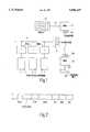
- FIG. 1is a block diagram of a portion of an X-ray device according to the invention.
- FIG. 2shows a data arrangement in accordance with the CAN protocol.
- Reference numerals 1, 2 and 3 in FIG. 1denote three data transmission nodes whose data inputs and outputs are connected to a bus system 4.
- Each data transmission nodeis associated with a component of the X-ray device which is controlled by the relevant node.
- a component 5is connected to the node 1, for example a drive for tilting the tabletop of a patient table about a horizontal axis.
- a component 6is associated with the node 2, for example a drive for shifting the tabletop in longitudinal direction, and the component 7 controlled by the node 3 may be a drive for shifting the tabletop in lateral direction.
- Further data transmission nodesare connected to the bus 4, each with its associated component of the X-ray device, but these units are not represented in the drawing.
- the bus 4is connected to an infrared converter 8.
- the infrared converter 8comprises a transmitter T which converts the data on the bus into infrared signals, the infrared converter emitting light in the case of a dominant bit and no light in the case of a recessive bit.
- the infrared converteralso comprises a receiver R which converts infrared signals into electrical signals on the bus.
- each infrared converter 90 or 100comprises a transmitter T which is connected to a data output (not shown) of the node and with an infrared receiver R which is connected to a data input (not shown) of the node.
- the convertersare so arranged that each transmitter can reach each receiver--with the exception of at most the receiver belonging to the same converter; however, it is advantageous when each infrared transmitter can also reach the infrared receiver in the same converter.
- the node 9controls, for example, a display 92 through lines 91, while the node 10 is connected, for example, to an operating unit 102 through lines 101.
- the data transmission as usual in the CAN protocolwill be explained below with reference to the example of the control of the patient table movement by means of the operating unit 102, it being assumed, for example, that the user has put in a command for the patient table movement into the operating unit 102.
- the associated infrared transmitterthen transmits a message, a so-called communication object, which reaches all infrared receivers (with the exception of at most the infrared receiver present in converter 100) and whose data frame is depicted in FIG. 2.
- the data framecontains first a start bit, whose logic level (D) is dominant, i.e. the transmitter emits infrared radiation during the transmission of this bit.
- the start bitis followed by an arbitration field with a length of twelve bits.
- the first eleven bitscontain the "identifier" of the communication object which characterizes the data to be transmitted (but not the relevant node) and which serves inter alia to determine which communication object takes precedence in the case of several nodes transmitting simultaneously. Indeed, when several nodes start transmitting different messages simultaneously, all those nodes which transmit a recessive bit (no light) during the transmission of the identifier associated with their message but which had received a dominant bit (light), will discontinue their transmission. The only remaining node is the one which transmits the message of highest priority, whose identifier accordingly contains more high bits at the start than the identifiers transmitted by the other nodes.
- CTRLcontrol field
- data fieldof between 0 and 64 bits length
- testing fieldcyclic redundancy check
- ACKreception acknowledge field
- the relevant transmitting nodewill repeat its message when not at least one node acknowledges the correct reception or when a node sends an error signal (seven high bits); if not, the end of the message is signalled by means of a final data field comprising seven low bits.
- the node(s) for which the message or communication object was meantwill react, because the identifier of this communication object was laid down in a memory location in the node, in this case the node 1 which controls the drive 5 for the patient table movement.
- the nodemay transmit a message about the patient table position at regular time intervals or, for example, when a particular position--for example, the horizontal position--has been reached, which message is transmitted by the transmitter of the infrared converter 8, reaches in the same manner as described above inter alia the receivers of the nodes 9 and 10, and causes the node 9 to show the transmitted patient table position on the display 92. Since the transmission reliability to the node 9 is safeguarded by the CAN protocol and since the control of the display unit 92 takes place via a line connection, it may be assumed that also in surroundings with interference sources the transmission reliability is guaranteed.
- the X-ray devicemay also comprise more than two components which are controllable by means of messages transmitted by remote control to the associated nodes.
- the communication of those data transmission nodes with the remaining CAN systemwill be wireless.
- the components of whichare mobile and/or which have a low power consumption, so that a battery is sufficient for operation and additional connections (apart from the connection to the relevant node) are not necessary.
- Testing or diagnostic units necessary for servicing purposesare advantageously coupled to the other components of the X-ray device by means of wireless signal converters or infrared transmitters and receivers.
Landscapes
- Engineering & Computer Science (AREA)
- General Engineering & Computer Science (AREA)
- Theoretical Computer Science (AREA)
- General Physics & Mathematics (AREA)
- Computer Hardware Design (AREA)
- Physics & Mathematics (AREA)
- Signal Processing (AREA)
- Computer Networks & Wireless Communication (AREA)
- Mobile Radio Communication Systems (AREA)
- Optical Communication System (AREA)
- Communication Control (AREA)
- Apparatus For Radiation Diagnosis (AREA)
- X-Ray Techniques (AREA)
Abstract
Description
1. Field of the Invention
The invention relates to an X-ray device comprising a number of components to each of which is assigned a data transmission node working by the CAN protocol whose data input and data output are in mutual communication with other data transmission nodes via transmitters and receivers, the data transmission nodes being connected to the relevant associated components through connection lines.
2. Description of the Related Art
Such an X-ray device is known from DE-A-40 25 834, corresponding to U.S. application Ser. No. 07/738395 to the same assignee as the present application.
The CAN protocol is known inter alia from the Intel publication "82526 Serial Communications Controller Architectural Overview"(ordering number: 270678001) and from the journal "Elektronik"(no. 25, 08.12.1989, pp. 79-83 and no. 12, 08.06.1990, pp. 109-114). In the CAN protocol, data are defined by the two logic levels "dominant" and "recessive". A dominant bit is obtained when one or several (data transmission) node(s) transmit(s) a dominant bit. A recessive bit is obtained only when all nodes generate such a bit. The information is coded in an NRZ code, i.e. the logic level does not change in the case of several consecutive bits of the same level.
According to the CAN protocol, each node can transmit data to each of the other nodes at any time (Multimaster principle) without having to wait for an authorization to transmit. The exchange of information accordingly takes place very quickly, which is essential for at least some components in an X-ray device.
According to the CAN protocol, each message (messages are also referred to as "communication objects" in the CAN protocol) comprises a so-called identifier which characterizes the nature of the data to be transmitted and which is transmitted following a start bit. When several data nodes start transmitting simultaneously, those nodes which transmit a recessive bit during transmission of the identifier, but which received a dominant bit, break off their transmission, so that only one data node is capable of transmitting the subsequent data of the message. Those nodes which received the data and test words of the transmitter correctly transmit an acknowledge signal (ACK signal) before the relevant transmitting node has ended a transmission. Those nodes which detect a faulty transmission transmit an error signal which causes all other nodes also to transmit an error signal and the transmitting node to break off the transmission and to repeat it. As a result, data nodes working in accordance with the CAN protocol have a high transmission speed as well as a high transmission reliability.
In the known X-ray device, the individual data transmission nodes are interconnected by means of optical waveguides combined into a loop. The time available for the transmission of a bit must be longer than the time required by the optical signal for reaching the last node in the loop jumping from node to node. The advantages of the high data transmission speed provided by the CAN protocol are partly wiped out again thereby. In the known device, moreover, difficulties may arise when an additional component is to be included in the x-ray device (in such a case an additional data transmission node must be included in the optical waveguide loop by means of additional waveguides), and when components perform strong movements relative to other components, because the associated data transmission nodes are in connection with the other data transmission nodes via optical waveguides.
The invention accordingly has for its object to provide an X-ray device of the kind mentioned in the opening paragraph which is so arranged that the number of components provided with a data transmission node or the spatial position of individual components can be changed in a simple manner while a high data transmission speed is maintained.
According to the invention, this object is achieved in that the transmitter and receiver of at least some of the data transmission nodes are constructed for wireless transmission, and in that these transmitters or receivers are so controlled that they transmit data to at least the wireless receivers of other data transmission nodes and receive data from the wireless transmitters of at least other data transmission nodes, as applicable.
The desired flexibility as to the number of data transmission nodes and the displacement possibility for individual components are achieved here by the wireless transmission, i.e. by a transmission without electrical conductors or optical waveguides. The high access speed to other nodes provided by systems according to the CAN protocol is maintained because each of the nodes transmitting in the wireless manner can reach each and any of the other nodes transmitting in the wireless manner at any time.
It should be noted here that the wireless data transmission is known in other technical fields.
Thus U.S. Pat. No. 4,775,928 discloses a system with a host computer which can enter into wireless communication with a portable terminal comprising a keyboard. The wireless transmission in this case takes place by means of high-frequency electromagnetic waves. Data put in at the terminal are transmitted to the host computer and transmitted back to the terminal by this computer, and only then are they displayed by the terminal; this two-way transmission reduces the transmission speed. When two or more terminals are provided, the host computer must communicate with these terminals by means of different security codes. This system is suitable only for data exchange between one central station and one or several satellite stations.
GB-PS 2,166,328, moreover, describes a home distribution system in which various stations, such as TV receiver, video recorder, stereo-radio combination, and at most one remote control unit per room can communicate with one another via a common ISDN bus. The (infrared) remote control unit here may enter into communication with other stations v/a an infrared adapter connected to the ISDN bus; the infrared connection between remote control unit and adapter accordingly only connects one transmitter to one receiver at a time. The data flow through the ISDN bus is controlled by a central unit so that only one of the stations connected to the bus can transmit data at any time. For this purpose, the central unit may, for example, call up the addresses of the stations one after the other. If the station called up at a given moment is ready to transmit, it transmits a (Service Request-SRQ) signal and subsequently receives authority to transmit from the central station. The relevant station then transmits its message, which contains inter alia the address of another station and a test word, and the addressed station transmits an acknowledge signal when the test word was correctly received. This process is suitable only for applications in which comparatively long waiting times are acceptable until the authority to transmit is given.
According to the invention, all data transmission nodes could in principle be provided with a transmitter and a receiver for wireless transmission. This, however, does not make sense in all cases. For components which are arranged close together and which do not change their relative positions, for example, the data transmission through lines is in general more suitable than wireless transmission because the former as a rule leads to a greater freedom from interference. A further embodiment therefore is characterized in that a wireless transmitter which can reach the other wireless receivers or a wireless receiver which can receive data from the other wireless transmitters is connected to a line bus system to which at the same time several data transmission nodes are connected.
Here, accordingly, there are two groups of nodes. The nodes of the one group are connected to the bus system, whereas the nodes of the other group are each connected to a wireless transmitter/receiver. A node from the one group comes into contact with a node from the other group via a wireless transmitter (at one of the nodes or at the bus) and a wireless receiver (at the bus or at one of the nodes). In such a ease, the nodes of mobile or newly added components of the X-ray device will appropriately be provided with wireless transmitters and receivers, but the same holds for operating elements or display units. Similarly, this arrangement is suitable for the plugless connection of servicing or diagnostic systems to the data transmission nodes of the components of an X-ray device.
The invention will be explained in more detail below with reference to the drawing, in which
FIG. 1 is a block diagram of a portion of an X-ray device according to the invention, and
FIG. 2 shows a data arrangement in accordance with the CAN protocol.
In addition, thebus 4 is connected to an infrared converter 8. The infrared converter 8 comprises a transmitter T which converts the data on the bus into infrared signals, the infrared converter emitting light in the case of a dominant bit and no light in the case of a recessive bit. The infrared converter also comprises a receiver R which converts infrared signals into electrical signals on the bus.
Besides the group of nodes (1, 2, 3) connected to theline bus system 4, there is a further group of nodes. Thesenodes infrared converters infrared converter node 9 controls, for example, adisplay 92 throughlines 91, while thenode 10 is connected, for example, to anoperating unit 102 throughlines 101.
The data transmission as usual in the CAN protocol will be explained below with reference to the example of the control of the patient table movement by means of theoperating unit 102, it being assumed, for example, that the user has put in a command for the patient table movement into theoperating unit 102. The associated infrared transmitter then transmits a message, a so-called communication object, which reaches all infrared receivers (with the exception of at most the infrared receiver present in converter 100) and whose data frame is depicted in FIG. 2. The data frame contains first a start bit, whose logic level (D) is dominant, i.e. the transmitter emits infrared radiation during the transmission of this bit.
The start bit is followed by an arbitration field with a length of twelve bits. The first eleven bits contain the "identifier" of the communication object which characterizes the data to be transmitted (but not the relevant node) and which serves inter alia to determine which communication object takes precedence in the case of several nodes transmitting simultaneously. Indeed, when several nodes start transmitting different messages simultaneously, all those nodes which transmit a recessive bit (no light) during the transmission of the identifier associated with their message but which had received a dominant bit (light), will discontinue their transmission. The only remaining node is the one which transmits the message of highest priority, whose identifier accordingly contains more high bits at the start than the identifiers transmitted by the other nodes.
This is followed by a control field (CTRL) of six bits, a data field of between 0 and 64 bits length, a testing field (cyclic redundancy check, CRC) of 16 bits, and a reception acknowledge field (ACK) which comprises two bits which are low for the transmitting node. Each node which has received the transmitted message free from errors, will transmit a dominant bit (light) during the second of these two bits, also when the message was not meant for this node. The relevant transmitting node will repeat its message when not at least one node acknowledges the correct reception or when a node sends an error signal (seven high bits); if not, the end of the message is signalled by means of a final data field comprising seven low bits.
After all nodes have received the message in this manner and acknowledged it as correct, the node(s) for which the message or communication object was meant will react, because the identifier of this communication object was laid down in a memory location in the node, in this case thenode 1 which controls thedrive 5 for the patient table movement.
During the patient table movement, the node may transmit a message about the patient table position at regular time intervals or, for example, when a particular position--for example, the horizontal position--has been reached, which message is transmitted by the transmitter of the infrared converter 8, reaches in the same manner as described above inter alia the receivers of thenodes node 9 to show the transmitted patient table position on thedisplay 92. Since the transmission reliability to thenode 9 is safeguarded by the CAN protocol and since the control of thedisplay unit 92 takes place via a line connection, it may be assumed that also in surroundings with interference sources the transmission reliability is guaranteed.
The X-ray device may also comprise more than two components which are controllable by means of messages transmitted by remote control to the associated nodes. Advantageously, the communication of those data transmission nodes with the remaining CAN system will be wireless. The components of which are mobile and/or which have a low power consumption, so that a battery is sufficient for operation and additional connections (apart from the connection to the relevant node) are not necessary. Testing or diagnostic units necessary for servicing purposes are advantageously coupled to the other components of the X-ray device by means of wireless signal converters or infrared transmitters and receivers.
Claims (8)
1. An X-ray device comprising a multiplicity of operative components which communicate automatically with each other and cooperate to form said X-ray device, a plurality of said operative components being controlled in response to control commands transmitted from other ones of said components and each of said operative components being assigned a data transmission node working by the Controller Area Network protocol, the data transmission nodes being in mutual communication with each other via a data transmission system for transmission of data between said components including transmission of said control commands to said plurality of controllable components, the data transmission nodes being connected to the relevant associated components through connection lines, wherein said data transmission system comprises a first wireless transmitter and a first wireless receiver serving a first group of one or more data transmission nodes, a second wireless transmitter and a second wireless receiver serving a second group of one or more data transmission nodes and a third wireless transmitter and a third wireless receiver serving a third group of one or more data transmission nodes, each of said wireless transmitters serving any particular group of nodes being positioned for simultaneous broadcast mode wireless communication with each of said wireless receivers serving any other group of nodes.
2. An X-ray device as claimed in claim 1, wherein the first and second and third wireless transmitters and first and second and third wireless receivers are light transmitters and light receivers.
3. An X-ray device as claimed in claim 2, wherein said first group of data transmission nodes comprises at least two nodes connected via a line bus system to said first wireless transmitter and first wireless receiver.
4. An X-ray device as claimed in claim 1, wherein the light transmitters and light receivers are infrared transmitters and infrared receivers.
5. An X-ray device as claimed in claim 4, wherein said first group of data transmission nodes comprises at least two nodes connected via a line bus system to said first wireless transmitter and first wireless receiver.
6. An X-ray device as claimed in claim 1, wherein said first group of data transmission nodes comprises at least two nodes connected via a line bus system to said first wireless transmitter and first wireless receiver.
7. An X-ray device as claimed in claim 1 wherein said at least one controllable component is a drive for patient positioning.
8. An X-ray device as claimed in claim 1 wherein each of said wireless transmitters serving any particular group of nodes is positioned for simultaneous broadcast mode wireless communication also with said wireless receiver serving said particular group of nodes.
Applications Claiming Priority (2)
| Application Number | Priority Date | Filing Date | Title |
|---|---|---|---|
| DE4303643ADE4303643A1 (en) | 1993-02-09 | 1993-02-09 | X-ray system |
| DE4303643.0 | 1993-02-09 |
Publications (1)
| Publication Number | Publication Date |
|---|---|
| US5596437Atrue US5596437A (en) | 1997-01-21 |
Family
ID=6479918
Family Applications (1)
| Application Number | Title | Priority Date | Filing Date |
|---|---|---|---|
| US08/194,300Expired - Fee RelatedUS5596437A (en) | 1993-02-09 | 1994-02-08 | X-ray device |
Country Status (4)
| Country | Link |
|---|---|
| US (1) | US5596437A (en) |
| EP (1) | EP0610999B1 (en) |
| JP (1) | JPH06291808A (en) |
| DE (2) | DE4303643A1 (en) |
Cited By (70)
| Publication number | Priority date | Publication date | Assignee | Title |
|---|---|---|---|---|
| US5946215A (en)* | 1996-01-23 | 1999-08-31 | Mitsubishi Denki Kabushiki Kaisha | Machine tool controlling network communication controlling system |
| US5953681A (en)* | 1996-07-30 | 1999-09-14 | Bayer Corporation | Autonomous node for a test instrument system having a distributed logic nodal architecture |
| EP0981994A1 (en)* | 1998-08-25 | 2000-03-01 | General Electric Company | Methods and apparatus for exchanging data in an imaging system |
| US6366723B1 (en)* | 1998-09-16 | 2002-04-02 | Jolt Ltd. | Wireless optical communications without electronics |
| US20020044660A1 (en)* | 1996-02-22 | 2002-04-18 | Lars-Berno Fredriksson | Device in a system operating with CAN-protocol and in a control and/or supervision system |
| US6398409B1 (en)* | 1999-03-16 | 2002-06-04 | Hill-Rom Services, Inc. | Patient support with digital X-ray cassette |
| WO2002083002A1 (en)* | 2001-04-13 | 2002-10-24 | Koninklijke Philips Electronics N.V. | Medical imaging device, method and computer program for use in a safety critical environment |
| US6575624B2 (en) | 2000-06-29 | 2003-06-10 | Siemens Aktiengesellschaft | X-ray apparatus with non-contacting transmission of data or energy between mechanically connected components |
| US6717653B2 (en) | 2000-06-23 | 2004-04-06 | Canon Kabushiki Kaisha | Moving mechanism in exposure apparatus, and exposure apparatus having the same |
| US20100102948A1 (en)* | 2008-10-27 | 2010-04-29 | Lennox Industries Inc. | Alarm and diagnostics system and method for a distributed architecture heating, ventilation and air conditioning network |
| US20100106323A1 (en)* | 2008-10-27 | 2010-04-29 | Lennox Industries Inc. | Communication protocol system and method for a distributed-architecture heating, ventilation and air conditioning network |
| US20100107110A1 (en)* | 2008-10-27 | 2010-04-29 | Lennox Industries Inc. | System and method of use for a user interface dashboard of a heating, ventilation and air conditioning network |
| US20100106320A1 (en)* | 2008-10-27 | 2010-04-29 | Lennox Industries Inc. | Communication protocol system and method for a distributed-architecture heating, ventilation and air conditioning network |
| US20100106319A1 (en)* | 2008-10-27 | 2010-04-29 | Lennox Industries Inc. | Method of controlling equipment in a heating, ventilation and air conditioning network |
| US20100106313A1 (en)* | 2008-10-27 | 2010-04-29 | Lennox Industries Inc. | Device abstraction system and method for a distributed architecture heating, ventilation and air conditioning system |
| US20100107070A1 (en)* | 2008-10-27 | 2010-04-29 | Lennox Industries Incorporated | System and method of use for a user interface dashboard of a heating, ventilation and air conditioning network |
| US20100102136A1 (en)* | 2008-10-27 | 2010-04-29 | Lennox Industries Inc. | Alarm and diagnostics system and method for a distributed architecture heating, ventilation and air conditioning network |
| US20100106312A1 (en)* | 2008-10-27 | 2010-04-29 | Lennox Industries Inc. | Alarm and diagnostics system and method for a distributed-architecture heating, ventilation and air conditioning network |
| US20100107103A1 (en)* | 2008-10-27 | 2010-04-29 | Lennox Industries Inc. | System and method of use for a user interface dashboard of a heating, ventilation and air conditioning network |
| US20100107007A1 (en)* | 2008-10-27 | 2010-04-29 | Lennox Industries Inc. | System recovery in a heating, ventilation and air conditioning network |
| US20100106787A1 (en)* | 2008-10-27 | 2010-04-29 | Lennox Industries Inc. | Communication protocol system and method for a distributed architecture heating, ventilation and air conditioning network |
| US20100107071A1 (en)* | 2008-10-27 | 2010-04-29 | Lennox Industries Inc. | System and method of use for a user interface dashboard of a heating, ventilation and air conditioning network |
| US20100107076A1 (en)* | 2008-10-27 | 2010-04-29 | Lennox Industries Incorporation | System and method of use for a user interface dashboard of a heating, ventilation and air conditioning network |
| US20100106815A1 (en)* | 2008-10-27 | 2010-04-29 | Lennox Industries Inc. | Memory recovery scheme and data structure in a heating, ventilation and air conditioning network |
| US20100106311A1 (en)* | 2008-10-27 | 2010-04-29 | Lennox Industries Inc. | Alarm and diagnostics system and method for a distributed architecture heating, ventilation and conditioning network |
| US20100101854A1 (en)* | 2008-10-27 | 2010-04-29 | Lennox Industries Inc. | Flush wall mount thermostat and in-set mounting plate for a heating, ventilation and air conditioning system |
| US20100106327A1 (en)* | 2008-10-27 | 2010-04-29 | Lennox Industries Inc. | Communication protocol system and method for a distributed-architecture heating, ventilation and air conditioning network |
| US20100107073A1 (en)* | 2008-10-27 | 2010-04-29 | Lennox Industries Inc. | System and method of use for a user interface dashboard of a heating, ventilation and air conditioning network |
| US20100106317A1 (en)* | 2008-10-27 | 2010-04-29 | Lennox Industries Inc. | Device abstraction system and method for a distributed- architecture heating, ventilation and air conditioning system |
| US20100106307A1 (en)* | 2008-10-27 | 2010-04-29 | Lennox Industries Inc. | Device abstraction system and method for a distributed-architecture heating, ventilation and air conditioning system |
| US20100107232A1 (en)* | 2008-10-27 | 2010-04-29 | Lennox Industries Inc. | Communication protocol system and method for a distributed-architecture heating, ventilation and air conditioning network |
| US20100106321A1 (en)* | 2008-10-27 | 2010-04-29 | Lennox Industries Inc. | Memory recovery scheme and data structure in a heating, ventilation and air conditioning network |
| US20100107083A1 (en)* | 2008-10-27 | 2010-04-29 | Lennox Industries Inc. | Memory recovery scheme and data structure in a heating, ventilation and air conditioning network |
| US20100106324A1 (en)* | 2008-10-27 | 2010-04-29 | Lennox Industries Inc. | Communication protocol system and method for a distributed-architecture heating, ventilation and air conditioning network |
| US20100106326A1 (en)* | 2008-10-27 | 2010-04-29 | Lennox Industries Inc. | Communication protocol system and method for a distributed-architecture heating, ventilation and air conditioning network |
| US20100106925A1 (en)* | 2008-10-27 | 2010-04-29 | Lennox Industries Inc. | Programming and configuration in a heating, ventilation and air conditioning network |
| US20100102973A1 (en)* | 2008-10-27 | 2010-04-29 | Lennox Industries, Inc. | Alarm and diagnostics system and method for a distributed-architecture heating, ventilation and air conditioning network |
| US20100106315A1 (en)* | 2008-10-27 | 2010-04-29 | Lennox Industries Inc. | System recovery in a heating, ventilation and air conditioning network |
| US20100107112A1 (en)* | 2008-10-27 | 2010-04-29 | Lennox Industries Inc. | System and method of use for a user interface dashboard of a heating, ventilation and air conditioning network |
| US20100106957A1 (en)* | 2008-10-27 | 2010-04-29 | Lennox Industries Inc. | Programming and configuration in a heating, ventilation and air conditioning network |
| US20100106316A1 (en)* | 2008-10-27 | 2010-04-29 | Lennox Industries Inc. | Alarm and diagnostics system and method for a distributed architecture heating, ventilation and air conditioning network |
| US20100106810A1 (en)* | 2008-10-27 | 2010-04-29 | Lennox Industries Inc. | Communication protocol system and method for a distributed-architecture heating, ventilation and air conditioning network |
| US20100106318A1 (en)* | 2008-10-27 | 2010-04-29 | Lennox Industries Inc. | Alarm and diagnostics system and method for a distributed- architecture heating, ventilation and air conditioning network |
| US20100106309A1 (en)* | 2008-10-27 | 2010-04-29 | Lennox Industries Inc. | General control techniques in a heating, ventilation and air conditioning network |
| US20100107072A1 (en)* | 2008-10-27 | 2010-04-29 | Lennox Industries Inc. | System and method of use for a user interface dashboard of a heating, ventilation and air conditioning network |
| US20100106314A1 (en)* | 2008-10-27 | 2010-04-29 | Lennox Industries Inc. | System recovery in a heating, ventilation and air conditioning network |
| US20100107109A1 (en)* | 2008-10-27 | 2010-04-29 | Lennox Industries, Incorporated | System and method of use for a user interface dashboard of a heating, ventilation and air conditioning network |
| US20100179696A1 (en)* | 2008-10-27 | 2010-07-15 | Lennox Industries Inc. | Device abstraction system and method for a distributed-architecture heating, ventilation and air conditioning system |
| US20110202180A1 (en)* | 2010-02-17 | 2011-08-18 | Lennox Industries, Incorporated | Auxiliary controller, a hvac system, a method of manufacturing a hvac system and a method of starting the same |
| USD648642S1 (en) | 2009-10-21 | 2011-11-15 | Lennox Industries Inc. | Thin cover plate for an electronic system controller |
| USD648641S1 (en) | 2009-10-21 | 2011-11-15 | Lennox Industries Inc. | Thin cover plate for an electronic system controller |
| US8352081B2 (en) | 2008-10-27 | 2013-01-08 | Lennox Industries Inc. | Communication protocol system and method for a distributed-architecture heating, ventilation and air conditioning network |
| US8393026B2 (en) | 2005-11-07 | 2013-03-12 | Stryker Corporation | Hospital bed |
| US8442693B2 (en) | 2008-10-27 | 2013-05-14 | Lennox Industries, Inc. | System and method of use for a user interface dashboard of a heating, ventilation and air conditioning network |
| US8452906B2 (en) | 2008-10-27 | 2013-05-28 | Lennox Industries, Inc. | Communication protocol system and method for a distributed-architecture heating, ventilation and air conditioning network |
| US8548630B2 (en) | 2008-10-27 | 2013-10-01 | Lennox Industries, Inc. | Alarm and diagnostics system and method for a distributed-architecture heating, ventilation and air conditioning network |
| US8774210B2 (en) | 2008-10-27 | 2014-07-08 | Lennox Industries, Inc. | Communication protocol system and method for a distributed-architecture heating, ventilation and air conditioning network |
| US8788100B2 (en) | 2008-10-27 | 2014-07-22 | Lennox Industries Inc. | System and method for zoning a distributed-architecture heating, ventilation and air conditioning network |
| US8855825B2 (en) | 2008-10-27 | 2014-10-07 | Lennox Industries Inc. | Device abstraction system and method for a distributed-architecture heating, ventilation and air conditioning system |
| US8954622B1 (en) | 2011-01-19 | 2015-02-10 | Marvell International Ltd. | Embedded programmable logic for logic stacking on application processor |
| US9009893B2 (en) | 1999-12-29 | 2015-04-21 | Hill-Rom Services, Inc. | Hospital bed |
| US9261888B2 (en) | 2008-10-27 | 2016-02-16 | Lennox Industries Inc. | System and method of use for a user interface dashboard of a heating, ventilation and air conditioning network |
| US20160072582A1 (en)* | 2014-09-09 | 2016-03-10 | Panasonic Intellectual Property Management Co., Ltd. | Visible light communication device and receiving device |
| US9432208B2 (en) | 2008-10-27 | 2016-08-30 | Lennox Industries Inc. | Device abstraction system and method for a distributed architecture heating, ventilation and air conditioning system |
| US9632490B2 (en) | 2008-10-27 | 2017-04-25 | Lennox Industries Inc. | System and method for zoning a distributed architecture heating, ventilation and air conditioning network |
| US9651925B2 (en) | 2008-10-27 | 2017-05-16 | Lennox Industries Inc. | System and method for zoning a distributed-architecture heating, ventilation and air conditioning network |
| US10052249B2 (en) | 2004-10-29 | 2018-08-21 | Stryker Corporation | Patient support with improved control |
| US11246776B2 (en) | 2005-12-19 | 2022-02-15 | Stryker Corporation | Patient support with improved control |
| US20240048404A1 (en)* | 2022-08-02 | 2024-02-08 | Stmicroelectronics Application Gmbh | Electronic device, corresponding bus communication system and method of configuring a bus communication system |
| US12425266B2 (en) | 2021-04-30 | 2025-09-23 | Autonetworks Technologies, Ltd. | Communication device, communication system, and communication method |
Families Citing this family (4)
| Publication number | Priority date | Publication date | Assignee | Title |
|---|---|---|---|---|
| EP0822405A3 (en)* | 1996-07-30 | 2004-07-07 | Bayer Corporation | Electronics system for a hematology analytical instrument |
| DE29800732U1 (en)* | 1998-01-17 | 1999-02-18 | Eckert, Hubert, 72622 Nürtingen | Optoelectronic device |
| DE10031776A1 (en)* | 2000-06-29 | 2002-01-17 | Siemens Ag | X-ray apparatus has sliding contact for transmitting data or power to electrical apparatus mounted on C-shaped frame |
| DE10150048A1 (en)* | 2001-10-10 | 2003-05-08 | Siemens Ag | Computer tomography apparatus for medical diagnostics, includes X-ray generator with operating unit having wireless data exchange devices selected from group of microwave devices or radio wave devices |
Citations (13)
| Publication number | Priority date | Publication date | Assignee | Title |
|---|---|---|---|---|
| JPS60259029A (en)* | 1984-06-05 | 1985-12-21 | Matsushita Electric Ind Co Ltd | Transmission controller |
| GB2166328A (en)* | 1984-10-27 | 1986-04-30 | Int Standard Electric Corp | In-house distribution facility for a broadband communication system |
| US4649385A (en)* | 1982-08-13 | 1987-03-10 | Teloc R & D Ltd. | Electronic locating system for persons receiving telephone calls |
| US4775928A (en)* | 1985-10-30 | 1988-10-04 | Westinghouse Electric Corp. | Hand-held wireless computer controller system |
| GB2204426A (en)* | 1987-05-08 | 1988-11-09 | Hauni Werke Koerber & Co Kg | Remote control apparatus for machine tools |
| US4809257A (en)* | 1985-04-02 | 1989-02-28 | International Business Machines Corporation | Hierarchical distributed infrared communication system |
| US4812842A (en)* | 1986-04-30 | 1989-03-14 | Koenig And Bauer A. G. | Device for the control of rotary printing machines |
| JPH01216634A (en)* | 1988-02-24 | 1989-08-30 | Matsushita Electric Works Ltd | Transmission system |
| EP0361585A2 (en)* | 1988-09-27 | 1990-04-04 | Matsushita Electric Works, Ltd. | Data setting system for terminal units in remote supervisory and controlling system employing multiplex data transmission |
| US4962466A (en)* | 1987-03-27 | 1990-10-09 | Viscom Systems, Inc. | Electronic product information display system |
| US4977618A (en)* | 1988-04-21 | 1990-12-11 | Photonics Corporation | Infrared data communications |
| JPH0479622A (en)* | 1990-07-20 | 1992-03-13 | Sekisui Chem Co Ltd | Home controller for optical communication |
| US5109222A (en)* | 1989-03-27 | 1992-04-28 | John Welty | Remote control system for control of electrically operable equipment in people occupiable structures |
Family Cites Families (4)
| Publication number | Priority date | Publication date | Assignee | Title |
|---|---|---|---|---|
| JPS61270949A (en)* | 1985-05-27 | 1986-12-01 | Matsushita Electric Ind Co Ltd | remote input/output device |
| JPS63164724A (en)* | 1986-12-26 | 1988-07-08 | Matsushita Electric Ind Co Ltd | Home system bus |
| DE4034154C2 (en)* | 1989-11-03 | 2000-06-21 | Meto International Gmbh | Arrangement for transferring data |
| DE4025834A1 (en)* | 1990-08-16 | 1992-02-20 | Philips Patentverwaltung | DATA TRANSMISSION DEVICE, ESPECIALLY FOR A X-RAY DIAGNOSTIC SYSTEM |
- 1993
- 1993-02-09DEDE4303643Apatent/DE4303643A1/ennot_activeWithdrawn
- 1994
- 1994-02-03EPEP94200287Apatent/EP0610999B1/ennot_activeExpired - Lifetime
- 1994-02-03DEDE59408189Tpatent/DE59408189D1/ennot_activeExpired - Fee Related
- 1994-02-08USUS08/194,300patent/US5596437A/ennot_activeExpired - Fee Related
- 1994-02-08JPJP6014454Apatent/JPH06291808A/enactivePending
Patent Citations (13)
| Publication number | Priority date | Publication date | Assignee | Title |
|---|---|---|---|---|
| US4649385A (en)* | 1982-08-13 | 1987-03-10 | Teloc R & D Ltd. | Electronic locating system for persons receiving telephone calls |
| JPS60259029A (en)* | 1984-06-05 | 1985-12-21 | Matsushita Electric Ind Co Ltd | Transmission controller |
| GB2166328A (en)* | 1984-10-27 | 1986-04-30 | Int Standard Electric Corp | In-house distribution facility for a broadband communication system |
| US4809257A (en)* | 1985-04-02 | 1989-02-28 | International Business Machines Corporation | Hierarchical distributed infrared communication system |
| US4775928A (en)* | 1985-10-30 | 1988-10-04 | Westinghouse Electric Corp. | Hand-held wireless computer controller system |
| US4812842A (en)* | 1986-04-30 | 1989-03-14 | Koenig And Bauer A. G. | Device for the control of rotary printing machines |
| US4962466A (en)* | 1987-03-27 | 1990-10-09 | Viscom Systems, Inc. | Electronic product information display system |
| GB2204426A (en)* | 1987-05-08 | 1988-11-09 | Hauni Werke Koerber & Co Kg | Remote control apparatus for machine tools |
| JPH01216634A (en)* | 1988-02-24 | 1989-08-30 | Matsushita Electric Works Ltd | Transmission system |
| US4977618A (en)* | 1988-04-21 | 1990-12-11 | Photonics Corporation | Infrared data communications |
| EP0361585A2 (en)* | 1988-09-27 | 1990-04-04 | Matsushita Electric Works, Ltd. | Data setting system for terminal units in remote supervisory and controlling system employing multiplex data transmission |
| US5109222A (en)* | 1989-03-27 | 1992-04-28 | John Welty | Remote control system for control of electrically operable equipment in people occupiable structures |
| JPH0479622A (en)* | 1990-07-20 | 1992-03-13 | Sekisui Chem Co Ltd | Home controller for optical communication |
Non-Patent Citations (9)
| Title |
|---|
| 82526 Serial Communications Controller Architectural Overview, Intel.* |
| Gantz, "Preventing Wiring Entanglements with Satellite Infrared Network", Info World, Jul. 24, 1989. |
| Gantz, Preventing Wiring Entanglements with Satellite Infrared Network , Info World, Jul. 24, 1989.* |
| Helliwell, "Wireless LANs: Coming to an Office Near You?", PC Week, Jul. 20, 1989 p. 20. |
| Helliwell, Wireless LANs: Coming to an Office Near You , PC Week, Jul. 20, 1989 p. 20.* |
| Nakata, "In House Wireless Communication System Using Infrared Radiation" International Conference on Computer Communication pp. 333-338, Nov. 1985. |
| Nakata, In House Wireless Communication System Using Infrared Radiation International Conference on Computer Communication pp. 333 338, Nov. 1985.* |
| Yen, "The Use of Directed Optical Beams in Wireless Communications" IEEE Globecom 1985, New Orleans, Dec. 2-5, 1985 pp. 1181-1184. |
| Yen, The Use of Directed Optical Beams in Wireless Communications IEEE Globecom 1985, New Orleans, Dec. 2 5, 1985 pp. 1181 1184.* |
Cited By (120)
| Publication number | Priority date | Publication date | Assignee | Title |
|---|---|---|---|---|
| US5946215A (en)* | 1996-01-23 | 1999-08-31 | Mitsubishi Denki Kabushiki Kaisha | Machine tool controlling network communication controlling system |
| US20080275996A1 (en)* | 1996-02-22 | 2008-11-06 | Kvaser Consultant Ab | Device in a system operating with can-protocol and in a control and/or supervision system |
| US7100042B2 (en)* | 1996-02-22 | 2006-08-29 | Kvaser Consultant Ab | Device in a system operating with CAN-protocol and in a control and/or supervision system |
| US8713301B2 (en) | 1996-02-22 | 2014-04-29 | Xinshu Management, L.L.C. | Device in a system operating with CAN-protocol and in a control and/or supervision system |
| US7386716B2 (en)* | 1996-02-22 | 2008-06-10 | Kvaser Consultant Ab | Device in a system operating with CAN-protocol and in a control and/or supervision system |
| US20020044660A1 (en)* | 1996-02-22 | 2002-04-18 | Lars-Berno Fredriksson | Device in a system operating with CAN-protocol and in a control and/or supervision system |
| US7100196B2 (en) | 1996-02-22 | 2006-08-29 | Kvaser Consultant Ab | Device in a system operating with CAN-protocol and in a control and/or supervision system |
| US6467039B1 (en) | 1996-02-22 | 2002-10-15 | Kvaser Consultant Ab | Device in a system operating with can-protocol and in a control and/or supervision system |
| US20030002681A1 (en)* | 1996-02-22 | 2003-01-02 | Lars-Berno Fredriksson | Device in a system operating with CAN-protocol and in a control and/or supervision system |
| US5953681A (en)* | 1996-07-30 | 1999-09-14 | Bayer Corporation | Autonomous node for a test instrument system having a distributed logic nodal architecture |
| EP0981994A1 (en)* | 1998-08-25 | 2000-03-01 | General Electric Company | Methods and apparatus for exchanging data in an imaging system |
| US6292919B1 (en) | 1998-08-25 | 2001-09-18 | General Electric Company | Methods and apparatus for exchanging data in an imaging system |
| US6366723B1 (en)* | 1998-09-16 | 2002-04-02 | Jolt Ltd. | Wireless optical communications without electronics |
| US6398409B1 (en)* | 1999-03-16 | 2002-06-04 | Hill-Rom Services, Inc. | Patient support with digital X-ray cassette |
| US10251797B2 (en) | 1999-12-29 | 2019-04-09 | Hill-Rom Services, Inc. | Hospital bed |
| US9009893B2 (en) | 1999-12-29 | 2015-04-21 | Hill-Rom Services, Inc. | Hospital bed |
| US6717653B2 (en) | 2000-06-23 | 2004-04-06 | Canon Kabushiki Kaisha | Moving mechanism in exposure apparatus, and exposure apparatus having the same |
| US6575624B2 (en) | 2000-06-29 | 2003-06-10 | Siemens Aktiengesellschaft | X-ray apparatus with non-contacting transmission of data or energy between mechanically connected components |
| WO2002083002A1 (en)* | 2001-04-13 | 2002-10-24 | Koninklijke Philips Electronics N.V. | Medical imaging device, method and computer program for use in a safety critical environment |
| US11382813B2 (en) | 2004-10-29 | 2022-07-12 | Stryker Corporation | Patient support with improved control |
| US10052249B2 (en) | 2004-10-29 | 2018-08-21 | Stryker Corporation | Patient support with improved control |
| US8393026B2 (en) | 2005-11-07 | 2013-03-12 | Stryker Corporation | Hospital bed |
| US11246776B2 (en) | 2005-12-19 | 2022-02-15 | Stryker Corporation | Patient support with improved control |
| US8295981B2 (en) | 2008-10-27 | 2012-10-23 | Lennox Industries Inc. | Device commissioning in a heating, ventilation and air conditioning network |
| US8463443B2 (en) | 2008-10-27 | 2013-06-11 | Lennox Industries, Inc. | Memory recovery scheme and data structure in a heating, ventilation and air conditioning network |
| US20100107103A1 (en)* | 2008-10-27 | 2010-04-29 | Lennox Industries Inc. | System and method of use for a user interface dashboard of a heating, ventilation and air conditioning network |
| US20100107007A1 (en)* | 2008-10-27 | 2010-04-29 | Lennox Industries Inc. | System recovery in a heating, ventilation and air conditioning network |
| US20100106787A1 (en)* | 2008-10-27 | 2010-04-29 | Lennox Industries Inc. | Communication protocol system and method for a distributed architecture heating, ventilation and air conditioning network |
| US20100107071A1 (en)* | 2008-10-27 | 2010-04-29 | Lennox Industries Inc. | System and method of use for a user interface dashboard of a heating, ventilation and air conditioning network |
| US20100107076A1 (en)* | 2008-10-27 | 2010-04-29 | Lennox Industries Incorporation | System and method of use for a user interface dashboard of a heating, ventilation and air conditioning network |
| US20100106815A1 (en)* | 2008-10-27 | 2010-04-29 | Lennox Industries Inc. | Memory recovery scheme and data structure in a heating, ventilation and air conditioning network |
| US20100106311A1 (en)* | 2008-10-27 | 2010-04-29 | Lennox Industries Inc. | Alarm and diagnostics system and method for a distributed architecture heating, ventilation and conditioning network |
| US20100101854A1 (en)* | 2008-10-27 | 2010-04-29 | Lennox Industries Inc. | Flush wall mount thermostat and in-set mounting plate for a heating, ventilation and air conditioning system |
| US20100106327A1 (en)* | 2008-10-27 | 2010-04-29 | Lennox Industries Inc. | Communication protocol system and method for a distributed-architecture heating, ventilation and air conditioning network |
| US20100107073A1 (en)* | 2008-10-27 | 2010-04-29 | Lennox Industries Inc. | System and method of use for a user interface dashboard of a heating, ventilation and air conditioning network |
| US20100106317A1 (en)* | 2008-10-27 | 2010-04-29 | Lennox Industries Inc. | Device abstraction system and method for a distributed- architecture heating, ventilation and air conditioning system |
| US20100106307A1 (en)* | 2008-10-27 | 2010-04-29 | Lennox Industries Inc. | Device abstraction system and method for a distributed-architecture heating, ventilation and air conditioning system |
| US20100107232A1 (en)* | 2008-10-27 | 2010-04-29 | Lennox Industries Inc. | Communication protocol system and method for a distributed-architecture heating, ventilation and air conditioning network |
| US20100106321A1 (en)* | 2008-10-27 | 2010-04-29 | Lennox Industries Inc. | Memory recovery scheme and data structure in a heating, ventilation and air conditioning network |
| US20100107083A1 (en)* | 2008-10-27 | 2010-04-29 | Lennox Industries Inc. | Memory recovery scheme and data structure in a heating, ventilation and air conditioning network |
| US20100106324A1 (en)* | 2008-10-27 | 2010-04-29 | Lennox Industries Inc. | Communication protocol system and method for a distributed-architecture heating, ventilation and air conditioning network |
| US20100106326A1 (en)* | 2008-10-27 | 2010-04-29 | Lennox Industries Inc. | Communication protocol system and method for a distributed-architecture heating, ventilation and air conditioning network |
| US20100106925A1 (en)* | 2008-10-27 | 2010-04-29 | Lennox Industries Inc. | Programming and configuration in a heating, ventilation and air conditioning network |
| US20100102973A1 (en)* | 2008-10-27 | 2010-04-29 | Lennox Industries, Inc. | Alarm and diagnostics system and method for a distributed-architecture heating, ventilation and air conditioning network |
| US20100106315A1 (en)* | 2008-10-27 | 2010-04-29 | Lennox Industries Inc. | System recovery in a heating, ventilation and air conditioning network |
| US20100107112A1 (en)* | 2008-10-27 | 2010-04-29 | Lennox Industries Inc. | System and method of use for a user interface dashboard of a heating, ventilation and air conditioning network |
| US20100106957A1 (en)* | 2008-10-27 | 2010-04-29 | Lennox Industries Inc. | Programming and configuration in a heating, ventilation and air conditioning network |
| US20100106316A1 (en)* | 2008-10-27 | 2010-04-29 | Lennox Industries Inc. | Alarm and diagnostics system and method for a distributed architecture heating, ventilation and air conditioning network |
| US20100106810A1 (en)* | 2008-10-27 | 2010-04-29 | Lennox Industries Inc. | Communication protocol system and method for a distributed-architecture heating, ventilation and air conditioning network |
| US20100106318A1 (en)* | 2008-10-27 | 2010-04-29 | Lennox Industries Inc. | Alarm and diagnostics system and method for a distributed- architecture heating, ventilation and air conditioning network |
| US20100106309A1 (en)* | 2008-10-27 | 2010-04-29 | Lennox Industries Inc. | General control techniques in a heating, ventilation and air conditioning network |
| US20100107072A1 (en)* | 2008-10-27 | 2010-04-29 | Lennox Industries Inc. | System and method of use for a user interface dashboard of a heating, ventilation and air conditioning network |
| US20100106314A1 (en)* | 2008-10-27 | 2010-04-29 | Lennox Industries Inc. | System recovery in a heating, ventilation and air conditioning network |
| US20100107109A1 (en)* | 2008-10-27 | 2010-04-29 | Lennox Industries, Incorporated | System and method of use for a user interface dashboard of a heating, ventilation and air conditioning network |
| US20100179696A1 (en)* | 2008-10-27 | 2010-07-15 | Lennox Industries Inc. | Device abstraction system and method for a distributed-architecture heating, ventilation and air conditioning system |
| US20100102948A1 (en)* | 2008-10-27 | 2010-04-29 | Lennox Industries Inc. | Alarm and diagnostics system and method for a distributed architecture heating, ventilation and air conditioning network |
| US20100106323A1 (en)* | 2008-10-27 | 2010-04-29 | Lennox Industries Inc. | Communication protocol system and method for a distributed-architecture heating, ventilation and air conditioning network |
| US20100107110A1 (en)* | 2008-10-27 | 2010-04-29 | Lennox Industries Inc. | System and method of use for a user interface dashboard of a heating, ventilation and air conditioning network |
| US8239066B2 (en) | 2008-10-27 | 2012-08-07 | Lennox Industries Inc. | System and method of use for a user interface dashboard of a heating, ventilation and air conditioning network |
| US8255086B2 (en) | 2008-10-27 | 2012-08-28 | Lennox Industries Inc. | System recovery in a heating, ventilation and air conditioning network |
| US20100106320A1 (en)* | 2008-10-27 | 2010-04-29 | Lennox Industries Inc. | Communication protocol system and method for a distributed-architecture heating, ventilation and air conditioning network |
| US20100102136A1 (en)* | 2008-10-27 | 2010-04-29 | Lennox Industries Inc. | Alarm and diagnostics system and method for a distributed architecture heating, ventilation and air conditioning network |
| US8352081B2 (en) | 2008-10-27 | 2013-01-08 | Lennox Industries Inc. | Communication protocol system and method for a distributed-architecture heating, ventilation and air conditioning network |
| US8352080B2 (en) | 2008-10-27 | 2013-01-08 | Lennox Industries Inc. | Communication protocol system and method for a distributed-architecture heating, ventilation and air conditioning network |
| US20100107070A1 (en)* | 2008-10-27 | 2010-04-29 | Lennox Industries Incorporated | System and method of use for a user interface dashboard of a heating, ventilation and air conditioning network |
| US8433446B2 (en) | 2008-10-27 | 2013-04-30 | Lennox Industries, Inc. | Alarm and diagnostics system and method for a distributed-architecture heating, ventilation and air conditioning network |
| US8437877B2 (en) | 2008-10-27 | 2013-05-07 | Lennox Industries Inc. | System recovery in a heating, ventilation and air conditioning network |
| US8437878B2 (en) | 2008-10-27 | 2013-05-07 | Lennox Industries Inc. | Alarm and diagnostics system and method for a distributed architecture heating, ventilation and air conditioning network |
| US8442693B2 (en) | 2008-10-27 | 2013-05-14 | Lennox Industries, Inc. | System and method of use for a user interface dashboard of a heating, ventilation and air conditioning network |
| US8452456B2 (en) | 2008-10-27 | 2013-05-28 | Lennox Industries Inc. | System and method of use for a user interface dashboard of a heating, ventilation and air conditioning network |
| US8452906B2 (en) | 2008-10-27 | 2013-05-28 | Lennox Industries, Inc. | Communication protocol system and method for a distributed-architecture heating, ventilation and air conditioning network |
| US8463442B2 (en) | 2008-10-27 | 2013-06-11 | Lennox Industries, Inc. | Alarm and diagnostics system and method for a distributed architecture heating, ventilation and air conditioning network |
| US20100106312A1 (en)* | 2008-10-27 | 2010-04-29 | Lennox Industries Inc. | Alarm and diagnostics system and method for a distributed-architecture heating, ventilation and air conditioning network |
| US8543243B2 (en) | 2008-10-27 | 2013-09-24 | Lennox Industries, Inc. | System and method of use for a user interface dashboard of a heating, ventilation and air conditioning network |
| US8548630B2 (en) | 2008-10-27 | 2013-10-01 | Lennox Industries, Inc. | Alarm and diagnostics system and method for a distributed-architecture heating, ventilation and air conditioning network |
| US8560125B2 (en) | 2008-10-27 | 2013-10-15 | Lennox Industries | Communication protocol system and method for a distributed-architecture heating, ventilation and air conditioning network |
| US8564400B2 (en) | 2008-10-27 | 2013-10-22 | Lennox Industries, Inc. | Communication protocol system and method for a distributed-architecture heating, ventilation and air conditioning network |
| US8600558B2 (en) | 2008-10-27 | 2013-12-03 | Lennox Industries Inc. | System recovery in a heating, ventilation and air conditioning network |
| US8600559B2 (en) | 2008-10-27 | 2013-12-03 | Lennox Industries Inc. | Method of controlling equipment in a heating, ventilation and air conditioning network |
| US8615326B2 (en) | 2008-10-27 | 2013-12-24 | Lennox Industries Inc. | System and method of use for a user interface dashboard of a heating, ventilation and air conditioning network |
| US8655491B2 (en) | 2008-10-27 | 2014-02-18 | Lennox Industries Inc. | Alarm and diagnostics system and method for a distributed architecture heating, ventilation and air conditioning network |
| US8655490B2 (en) | 2008-10-27 | 2014-02-18 | Lennox Industries, Inc. | System and method of use for a user interface dashboard of a heating, ventilation and air conditioning network |
| US8661165B2 (en) | 2008-10-27 | 2014-02-25 | Lennox Industries, Inc. | Device abstraction system and method for a distributed architecture heating, ventilation and air conditioning system |
| US8694164B2 (en) | 2008-10-27 | 2014-04-08 | Lennox Industries, Inc. | Interactive user guidance interface for a heating, ventilation and air conditioning system |
| US20100106313A1 (en)* | 2008-10-27 | 2010-04-29 | Lennox Industries Inc. | Device abstraction system and method for a distributed architecture heating, ventilation and air conditioning system |
| US8725298B2 (en) | 2008-10-27 | 2014-05-13 | Lennox Industries, Inc. | Alarm and diagnostics system and method for a distributed architecture heating, ventilation and conditioning network |
| US8744629B2 (en) | 2008-10-27 | 2014-06-03 | Lennox Industries Inc. | System and method of use for a user interface dashboard of a heating, ventilation and air conditioning network |
| US8761945B2 (en) | 2008-10-27 | 2014-06-24 | Lennox Industries Inc. | Device commissioning in a heating, ventilation and air conditioning network |
| US8762666B2 (en) | 2008-10-27 | 2014-06-24 | Lennox Industries, Inc. | Backup and restoration of operation control data in a heating, ventilation and air conditioning network |
| US8774210B2 (en) | 2008-10-27 | 2014-07-08 | Lennox Industries, Inc. | Communication protocol system and method for a distributed-architecture heating, ventilation and air conditioning network |
| US8788100B2 (en) | 2008-10-27 | 2014-07-22 | Lennox Industries Inc. | System and method for zoning a distributed-architecture heating, ventilation and air conditioning network |
| US9678486B2 (en) | 2008-10-27 | 2017-06-13 | Lennox Industries Inc. | Device abstraction system and method for a distributed-architecture heating, ventilation and air conditioning system |
| US8798796B2 (en) | 2008-10-27 | 2014-08-05 | Lennox Industries Inc. | General control techniques in a heating, ventilation and air conditioning network |
| US8802981B2 (en) | 2008-10-27 | 2014-08-12 | Lennox Industries Inc. | Flush wall mount thermostat and in-set mounting plate for a heating, ventilation and air conditioning system |
| US8855825B2 (en) | 2008-10-27 | 2014-10-07 | Lennox Industries Inc. | Device abstraction system and method for a distributed-architecture heating, ventilation and air conditioning system |
| US8874815B2 (en) | 2008-10-27 | 2014-10-28 | Lennox Industries, Inc. | Communication protocol system and method for a distributed architecture heating, ventilation and air conditioning network |
| US8892797B2 (en) | 2008-10-27 | 2014-11-18 | Lennox Industries Inc. | Communication protocol system and method for a distributed-architecture heating, ventilation and air conditioning network |
| US9651925B2 (en) | 2008-10-27 | 2017-05-16 | Lennox Industries Inc. | System and method for zoning a distributed-architecture heating, ventilation and air conditioning network |
| US8977794B2 (en) | 2008-10-27 | 2015-03-10 | Lennox Industries, Inc. | Communication protocol system and method for a distributed-architecture heating, ventilation and air conditioning network |
| US8994539B2 (en) | 2008-10-27 | 2015-03-31 | Lennox Industries, Inc. | Alarm and diagnostics system and method for a distributed-architecture heating, ventilation and air conditioning network |
| US20100106319A1 (en)* | 2008-10-27 | 2010-04-29 | Lennox Industries Inc. | Method of controlling equipment in a heating, ventilation and air conditioning network |
| US9152155B2 (en) | 2008-10-27 | 2015-10-06 | Lennox Industries Inc. | Device abstraction system and method for a distributed-architecture heating, ventilation and air conditioning system |
| US9261888B2 (en) | 2008-10-27 | 2016-02-16 | Lennox Industries Inc. | System and method of use for a user interface dashboard of a heating, ventilation and air conditioning network |
| US9268345B2 (en) | 2008-10-27 | 2016-02-23 | Lennox Industries Inc. | System and method of use for a user interface dashboard of a heating, ventilation and air conditioning network |
| US9632490B2 (en) | 2008-10-27 | 2017-04-25 | Lennox Industries Inc. | System and method for zoning a distributed architecture heating, ventilation and air conditioning network |
| US9325517B2 (en) | 2008-10-27 | 2016-04-26 | Lennox Industries Inc. | Device abstraction system and method for a distributed-architecture heating, ventilation and air conditioning system |
| US9377768B2 (en) | 2008-10-27 | 2016-06-28 | Lennox Industries Inc. | Memory recovery scheme and data structure in a heating, ventilation and air conditioning network |
| US9432208B2 (en) | 2008-10-27 | 2016-08-30 | Lennox Industries Inc. | Device abstraction system and method for a distributed architecture heating, ventilation and air conditioning system |
| USD648641S1 (en) | 2009-10-21 | 2011-11-15 | Lennox Industries Inc. | Thin cover plate for an electronic system controller |
| USD648642S1 (en) | 2009-10-21 | 2011-11-15 | Lennox Industries Inc. | Thin cover plate for an electronic system controller |
| US9574784B2 (en) | 2010-02-17 | 2017-02-21 | Lennox Industries Inc. | Method of starting a HVAC system having an auxiliary controller |
| US9599359B2 (en) | 2010-02-17 | 2017-03-21 | Lennox Industries Inc. | Integrated controller an HVAC system |
| US8788104B2 (en) | 2010-02-17 | 2014-07-22 | Lennox Industries Inc. | Heating, ventilating and air conditioning (HVAC) system with an auxiliary controller |
| US8260444B2 (en) | 2010-02-17 | 2012-09-04 | Lennox Industries Inc. | Auxiliary controller of a HVAC system |
| US20110202180A1 (en)* | 2010-02-17 | 2011-08-18 | Lennox Industries, Incorporated | Auxiliary controller, a hvac system, a method of manufacturing a hvac system and a method of starting the same |
| US8954622B1 (en) | 2011-01-19 | 2015-02-10 | Marvell International Ltd. | Embedded programmable logic for logic stacking on application processor |
| US20160072582A1 (en)* | 2014-09-09 | 2016-03-10 | Panasonic Intellectual Property Management Co., Ltd. | Visible light communication device and receiving device |
| US12425266B2 (en) | 2021-04-30 | 2025-09-23 | Autonetworks Technologies, Ltd. | Communication device, communication system, and communication method |
| US20240048404A1 (en)* | 2022-08-02 | 2024-02-08 | Stmicroelectronics Application Gmbh | Electronic device, corresponding bus communication system and method of configuring a bus communication system |
| US12362963B2 (en)* | 2022-08-02 | 2025-07-15 | Stmicroelectronics Application Gmbh | Electronic device, corresponding bus communication system and method of configuring a bus communication system |
Also Published As
| Publication number | Publication date |
|---|---|
| EP0610999A1 (en) | 1994-08-17 |
| JPH06291808A (en) | 1994-10-18 |
| DE59408189D1 (en) | 1999-06-10 |
| DE4303643A1 (en) | 1994-08-11 |
| EP0610999B1 (en) | 1999-05-06 |
Similar Documents
| Publication | Publication Date | Title |
|---|---|---|
| US5596437A (en) | X-ray device | |
| US10397899B2 (en) | Wireless communication system and wireless communication control method, wireless communication device and wireless communication method, and computer program | |
| US4787082A (en) | Data flow control arrangement for local area network | |
| CA1300713C (en) | Gateway for use in load control system | |
| US5054022A (en) | Local communication bus system comprising a set of interconnected devices, a control bus, and a set of signal interconnections, and a device and a switchbox for use in such system | |
| US5012468A (en) | Master slave industrial token passing network | |
| US4509117A (en) | Communications network access rights arbitration | |
| US5463619A (en) | Local communication bus system comprising a set of interconnected devices, a control bus, and a set of signal interconnections, and a device and a switchbox for use in such system | |
| EP0143160B1 (en) | Address assignment to remote identical input/output devices | |
| HU214427B (en) | Data transfer system | |
| EP0360338B1 (en) | Local communication bus system comprising a set of interconnected devices, a control bus, and a set of signal interconnections, and a device and a switchbox for use in such system | |
| EP0589509A2 (en) | Polling-type digital communications system having pseudo-balanced mode | |
| EP0093578A2 (en) | Communications system | |
| US5383179A (en) | Message routing method in a system having several different transmission channels | |
| US6466989B1 (en) | Automatic network connection device for wiring to network cable | |
| JP3371938B2 (en) | Wireless communication system | |
| US5388109A (en) | Data communications device with resident link adapter | |
| JPH1098484A (en) | Active radio network for computer | |
| JPH01289339A (en) | Communication controller | |
| Hamabe et al. | Home bus system (HBS) interface LSI and its standard protocol example | |
| JP2695867B2 (en) | Elevator equipment | |
| JPH02281828A (en) | Data collecting/allotting system | |
| JPS58198941A (en) | Simple data transmitter | |
| JPS62169544A (en) | Multi-connection method for loop network | |
| JPH02196596A (en) | Communication control method |
Legal Events
| Date | Code | Title | Description |
|---|---|---|---|
| AS | Assignment | Owner name:U.S. PHILIPS CORPORATION, NEW YORK Free format text:ASSIGNMENT OF ASSIGNORS INTEREST;ASSIGNOR:HEINS, ERICH-JURGEN;REEL/FRAME:006909/0007 Effective date:19940308 | |
| FPAY | Fee payment | Year of fee payment:4 | |
| REMI | Maintenance fee reminder mailed | ||
| LAPS | Lapse for failure to pay maintenance fees | ||
| STCH | Information on status: patent discontinuation | Free format text:PATENT EXPIRED DUE TO NONPAYMENT OF MAINTENANCE FEES UNDER 37 CFR 1.362 | |
| FP | Expired due to failure to pay maintenance fee | Effective date:20050121 |