US5596336A - Low profile TEM mode slot array antenna - Google Patents
Low profile TEM mode slot array antennaDownload PDFInfo
- Publication number
- US5596336A US5596336AUS08/488,345US48834595AUS5596336AUS 5596336 AUS5596336 AUS 5596336AUS 48834595 AUS48834595 AUS 48834595AUS 5596336 AUS5596336 AUS 5596336A
- Authority
- US
- United States
- Prior art keywords
- array
- coupling slots
- horizontal
- vertical
- antenna
- Prior art date
- Legal status (The legal status is an assumption and is not a legal conclusion. Google has not performed a legal analysis and makes no representation as to the accuracy of the status listed.)
- Expired - Lifetime
Links
- 230000008878couplingEffects0.000claimsabstractdescription99
- 238000010168coupling processMethods0.000claimsabstractdescription99
- 238000005859coupling reactionMethods0.000claimsabstractdescription99
- 230000010287polarizationEffects0.000claimsabstractdescription64
- 239000000523sampleSubstances0.000claimsabstractdescription22
- 230000009977dual effectEffects0.000claimsabstractdescription13
- 238000003491arrayMethods0.000claimsdescription8
- 238000006243chemical reactionMethods0.000claimsdescription8
- 239000004020conductorSubstances0.000claims28
- 239000010410layerSubstances0.000description14
- 239000006260foamSubstances0.000description10
- 238000013459approachMethods0.000description4
- 230000005540biological transmissionEffects0.000description4
- 230000005855radiationEffects0.000description4
- 239000002356single layerSubstances0.000description3
- 238000004891communicationMethods0.000description2
- 239000003989dielectric materialSubstances0.000description2
- 238000004519manufacturing processMethods0.000description2
- 230000001902propagating effectEffects0.000description2
- 125000006850spacer groupChemical group0.000description2
- 230000001419dependent effectEffects0.000description1
- 230000009365direct transmissionEffects0.000description1
- 230000005684electric fieldEffects0.000description1
- 230000005284excitationEffects0.000description1
- 239000000463materialSubstances0.000description1
- 238000012986modificationMethods0.000description1
- 230000004048modificationEffects0.000description1
- 238000005457optimizationMethods0.000description1
- 230000010363phase shiftEffects0.000description1
- 230000001681protective effectEffects0.000description1
- 238000000926separation methodMethods0.000description1
- 230000003319supportive effectEffects0.000description1
Images


Classifications
- H—ELECTRICITY
- H01—ELECTRIC ELEMENTS
- H01Q—ANTENNAS, i.e. RADIO AERIALS
- H01Q13/00—Waveguide horns or mouths; Slot antennas; Leaky-waveguide antennas; Equivalent structures causing radiation along the transmission path of a guided wave
- H01Q13/10—Resonant slot antennas
- H—ELECTRICITY
- H01—ELECTRIC ELEMENTS
- H01Q—ANTENNAS, i.e. RADIO AERIALS
- H01Q15/00—Devices for reflection, refraction, diffraction or polarisation of waves radiated from an antenna, e.g. quasi-optical devices
- H01Q15/24—Polarising devices; Polarisation filters
- H01Q15/242—Polarisation converters
- H—ELECTRICITY
- H01—ELECTRIC ELEMENTS
- H01Q—ANTENNAS, i.e. RADIO AERIALS
- H01Q21/00—Antenna arrays or systems
- H01Q21/24—Combinations of antenna units polarised in different directions for transmitting or receiving circularly and elliptically polarised waves or waves linearly polarised in any direction
Definitions
- the present inventionrelates generally to a slot antenna and, more particularly, to a low profile dual polarization slot array antenna which is capable of providing dual circular or linear polarization radiation with optimum efficiency and bandwidth.
- Direct communication systemscommonly employ antennas for transmitting and receiving radiating energy between remote locations.
- antennasare widely employed for an increasing number of applications, many of which require a low profile, wide bandwidth antenna that can operate with polarized radiating energy.
- advanced Direct Broadcast SystemsDBS
- DBSDirect Broadcast Systems
- CPcircular polarized
- these broadcast systemsrequire low cost dual circular polarization eighteen inch aperture antennas at remote television locations for receiving the circular polarized radiating signals via satellite transponders.
- conventional reflector antennaswere commonly used which typically consisted of a reflector operatively coupled to a feed horn (polarizer) via a strut and an associated mounting structure.
- Such antennasinclude a Cassegrain antenna in which the feed horn is displaced from the reflector at a focal point on the front side thereof.
- Such conventional reflector antennasgenerally occupy a relatively large volume and are easily susceptible to damage from the environment.
- Low profile antenna conceptshave been developed which include planar slot antennas.
- One type of slot antennaincludes a double-layer structure which forms two propagation layers. Double-layer slot antennas historically have included the excitation of a transverse-electromagnetic (TEM) mode travelling wave between a pair of parallel metallic plates. This type of slot antenna further involves radio frequency (RF) energy leakage through radiating slots formed on the upper metallic plate so as to form a boresight pencil beam.
- TEMtransverse-electromagnetic
- RFradio frequency
- Such slot antennashave generally exhibited a relatively simple mechanical structure with potentially low fabrication costs.
- limitations associated with the conventional slot antenna approachesinclude the fact that either single feed designs or overly complicated multiple feed designs are generally employed to excite a pure TEM mode travelling wave between the parallel plates. While a number of feed design approaches have been proposed, the prior concepts are generally limited to a single polarization (CP or linear) or involve high complexity and exhibit low efficiency with a relatively narrow bandwidth.
- Another type of slot antennaincludes a radial line slot array antenna which has either a single or double layer structure with a plurality of coupling slots formed along a spiral pattern.
- a radial line slot array antennawhich has either a single or double layer structure with a plurality of coupling slots formed along a spiral pattern.
- An example of one such radial line slot antennais described in U.S. Pat. No. 5,175,561 issued to Goto.
- Such single-layer slot antennashave been employed for Direct Broadcast Systems in Japan and are generally capable of operating with single polarization energy only. That is, the radial line slot array may handle only either right hand or left hand circular polarization.
- An additional feed on another layercould be added to the single layer radial line slot array to provide dual circular polarization beams. However, the two beams would be dependent upon each other and optimization of one would degrade the other.
- the radial line slot arraygenerally is not capable of effectively handling the combination of both right hand and left hand circular polarization, while achieving reasonably acceptable bandwidth and performance criteria.
- a first beamforming feed networkcommunicates with an array of horizontal coupling slots, while a second beamforming feed network communicates with a vertical array of coupling slots. While the aforementioned slot antenna realizes several advancements over the conventional antennas such as a low profile assembly and efficient operation, the present invention is capable of providing increased compactness, enhanced efficiency with minimal feed line interference, among other advantages.
- a low profile planar dual polarization slot array antennawhich overcomes limitations which may be associated with the above-mentioned prior art approaches. More particularly, it is desirable to provide for a low profile slot antenna which realizes minimal signal interference and has a low profile assembly. It is further desirable to provide for a double-layered slot antenna which is capable of operating with both right hand and left hand circular polarization and involves relatively low fabrication costs and less complexity, while maintaining high efficiency and wide bandwidth capabilities. In addition, it is further desirable to provide for such a slot antenna which exhibits two circular polarized beams which are optimized independent of one another.
- a low profile slot antennawhich includes first and second oppositely disposed metallic plates with a dielectric layer disposed therebetween.
- An array of horizontal and vertical radiating elementsare formed in the first metallic plate.
- An array of horizontal and vertical coupling slotsare formed in the second metallic plate.
- the slot antennafurther includes a feed network having an array of feed lines which couple to individual ones of the horizontal and vertical coupling slots so that RF energy may pass therebetween.
- the feed networkis configured in a non-overlapping single plane with four sections, each of which couples signals to a conductive waveguide tube at or near the center of the feed network.
- a pair of orthogonal probesserve as input/output terminals between the waveguide tube and a transceiver.
- the slot antennamay operate to transmit and receive linearly polarized energy.
- the antennamay further include a polarization converter for converting between linear and circular polarization so as to allow for antenna operation with single or dual circular polarization energy.
- the polarization conversionmay be achieved with two sheets of Meanderline polarizers disposed above the upper metallic plate.
- a ninety degree hybrid couplermay be connected to the input/output terminals to provide polarization conversion between linear and circular polarization signals.
- FIG. 1is a view of a fully assembled low profile slot antenna according to the present invention
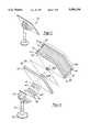
- FIG. 2is an exploded assembly view of the low profile slot antenna as shown in FIG. 1;
- FIG. 3is an exploded assembly view of a portion of the slot antenna shown in FIGS. 1 and 2 and taken from an elevated side view;
- FIG. 4is a partial cross-sectional view of the slot antenna according to the present invention.
- FIG. 5is a top view of an upper metallic plate of the slot antenna containing an array of radiating elements
- FIG. 6is an enlarged top view of a portion of the upper metallic plate shown in FIG. 5 further illustrating the configuration of the radiating elements;
- FIG. 7is a top view of a bottom metallic plate of the slot antenna containing an array of coupling slots in accordance with the present invention.
- FIG. 8is a schematic representation of a stripline feed network configured to cooperate with the array of coupling slots in accordance with the present invention
- FIG. 9illustrates a conductive waveguide tube centrally located within the slot antenna of the present invention.
- FIG. 10is a schematic representation of a Meanderline polarizer sheet which may be used according to one embodiment.
- FIG. 11illustrates the use of a ninety degree hybrid coupler for achieving polarization conversion according to an alternate embodiment.
- a low profile slot array antenna 10is shown therein in accordance with the present invention for handling dual polarization energy.
- the slot antenna 10has a low profile assembly with a thin planar energy radiation surface.
- the slot antenna 10 described hereinafteris designed to operate with transverse-electromagnetic (TEM) energy propagating within a pair of metallic plates. Further, the slot antenna is capable of transmitting and/or receiving both right hand and left hand circular polarized energy.
- the slot array antenna 10may be adapted to operate with linear (i.e., horizontal and vertical) polarization energy according to a second embodiment provided herein.
- the slot array antenna 10generally includes a pair of oppositely disposed metallic plates 12 and 16 which are separated from one another via a layer of dielectric material 14.
- Dielectric layer 14may generally have a dielectric constant of 1.1 or greater.
- the upper metallic plate 16generally includes a plurality of vertical and horizontal radiating elements (slots) arranged in a two-dimensional array, while the lower metallic plate 12 has a plurality of horizontal and vertical coupling slots formed therein.
- the metallic plates 12 and 16allow a transverse-electromagnetic (TEM) mode traveling wave to be excited therebetween.
- TEMtransverse-electromagnetic
- a feed network 28is disposed below lower metallic plate 12 and configured to communicate with the coupling slots formed in plate 12. Additionally, a foam sheet 26 dielectrically separates feed network 28 from lower metallic plate 12.
- the slot antenna 10further includes a pair of Meanderline polarizer sheets 20 and 24 disposed above the upper metallic plate 16 and separated therefrom via a foam sheet 18. Another foam sheet 22 is further disposed between the lower and upper Meanderline polarizer sheets 20 and 24 for providing a separation distance therebetween.
- An outer front cover 48preferably made of plastic or other non-conductive protective material, is disposed above Meanderline polarizer sheet 24 and separated therefrom via foam sheet 46.
- a rear plate 32is provided below the feed network 28 and is separated from network 28 via a foam sheet 30. Accordingly, radiating elements, coupling slots and the feed network 28 are sandwiched between front cover 48 and rear plate 32 and separated via dielectric foam sheets to provide a low profile planar radiation surface.
- the slot antenna 10has a conductive waveguide tube 50 protruding through the center portion of the antenna 10 extending from the bottom side through various layers into foam sheet 18.
- the conductive waveguide tube 50carries signals between the feed network 28 and a transceiver as will be described herein.
- Waveguide tube 50generally includes a top cap portion 50A and a bottom collar portion 50B which extends through layers 30 and 32 as well as a spacer layer 41.
- a circuit board 42is disposed between the spacer layer 41 and a cover 43.
- the waveguide tube 50communicates signals to and from conductive contacts on the circuit board 42.
- the circuit board 42may contain a transceiver, switching circuitry and signal traces as well as other electronic devices.
- slot antenna 10has an antenna bracket 70 against which the rear plate 32 is mounted via bolts or other fastener devices.
- the antenna bracket 70is connected to a mast assembly 72 which in turn is supported via a base member 74. Accordingly, slot antenna 10 is mounted and supported via the bracket 70, mast assembly 72 and base member 74.
- the upper metallic plate 16is shown containing an array of vertical radiating elements 34A and 34B and horizontal radiating elements 36A and 36B formed therein.
- the vertical and horizontal radiating elements 34A, 34B, 36A and 36Bare essentially very thin slots which extend through upper metallic plate 16 and are formed in parallel pairs.
- the array of radiating elementsare configured in four equal quadrants generally centered about the conductive waveguide tube 50.
- Each pair of vertical radiating elements 34A and 34Bpreferably has a vertical offset between the two radiating elements making up each corresponding pair. As illustrated in FIG. 6, the vertical offset is equal in distance to approximately one-quarter of a wavelength (1/4 ⁇ g ), where the wavelength ⁇ g is that of the TEM energy propagating within metallic plates 12 and 16.
- each pair of horizontal radiating elements 36A and 36Bpreferably has a horizontal offset equal to approximately one-quarter wavelength (1/4 ⁇ g ) of the TEM energy.
- Adjacent pairs of vertical radiating elements 34A and 34Bare displaced from each other the distance of about one wavelength ⁇ g of the operating TEM energy.
- adjacent pairs of horizontal radiating elements 36A and 36Bare also displaced from each other the distance of about one wavelength ⁇ g .
- linear polarized energyis able to efficiently pass through the radiating elements 34 and 36. In doing so, the horizontal polarization component thereof passes through metallic plate 16 via the vertical radiating elements 34A and 34B, while the vertical polarization component of the linear polarized energy passes therethrough via the horizontal radiating elements 36A and 36B.
- Each pair of radiating elements 34A, 34B, 36A and 36Bare preferably designed to have a length that may vary in length from the other pairs. This is because the length of the radiating elements 34A, 34B, 36A and 36B are designed such that a uniform amplitude of energy is radiated or received so as to provide for maximum antenna aperture efficiency.
- Vertical radiating elements 34A and 34Bwhich are in closer proximity to the corresponding vertical coupling slots on lower metallic plate 12 receive more energy and therefore have a shorter length, while the more distant radiating elements have a longer length to compensate for the lower amount of energy associated therewith.
- Horizontal radiating elements 36A and 36Blikewise have the same dimensional variations. Accordingly, the array of vertical radiating elements 34A and 34B can essentially be designed and optimized independent of the horizontal radiating elements 36A and 36B.
- the bottom metallic plate 12is shown in FIG. 7 and has a horizontal N ⁇ 1 array of rectangular coupling slots 40A and 40C and a vertical N ⁇ 1 array of rectangular coupling slots 40B and 40D formed therein.
- the horizontal coupling slots 40Aare shown on one side of waveguide tube 50, while the horizontal coupling slots 40C are provided on the opposite side.
- vertical coupling slots 40B and 40Dare provided on opposite sides of waveguide tube 50.
- the horizontal coupling slots 40A and 40Care arranged orthogonal to the vertical coupling slots 40B and 40D and are preferably centered about the conductive waveguide tube 50.
- the horizontal and vertical coupling slots 40A through 40Doperate to either excite the respective vertical and horizontal polarization energy onto the stripline feed network 28 or receive energy therefrom.
- the stripline feed network 28is disposed below the lower metallic plate 12 and separated therefrom via a dielectric layer 26.
- the feed network 28is fabricated on top surface of a dielectric material such as foam sheet 30 or fabricated on a separate dielectric sheet above foam sheet 30.
- a conductive ground planeis provided on the bottom side of foam sheet 30 or the separate dielectric sheet so as to form stripline circuitry making up the feed network 28.
- the feed network 28is preferably fabricated as stripline circuit traces with finger traces 54A through 54D which extend across a portion of individual ones of the horizontal and vertical coupling slots 40A through 40D.
- the feed network 28is configured with four similar sections 28A through 28D oriented at ninety degree intervals about a circular rotation of the conductive waveguide tube 50.
- the first feed network section 28Ahas a feed line 52A coupled to the waveguide tube 50 located at the center of the feed network 28. Feed line 52A branches and splits in half several times to provide the array of fingers 54A, each of which electrically couples to individual ones of the horizontal coupling slots 40A.
- each of the remaining feed network sections 28B through 28Dhas respective feed lines 52B through 52D center coupled to waveguide tube 50 and split several times to provide corresponding arrays of fingers 54B through 54D.
- Fingers 54Bare electrically coupled to the vertical array of coupling slots 40B, while fingers 54C and 54D are electrically coupled to respective horizontal coupling slots 40C and vertical coupling slots 40D.
- the feed network 28 configuration of the present inventionadvantageously allows for the realization of single layer signal traces which do not overlap.
- Other single plane feed network configurationssuch as a travelling wave feed could be used in lieu of feed network 28 shown herein to further reduce feed loss.
- alternate feed network configurationsmay exhibit a reduced bandwidth.
- Feed lines 52A through 52Dare physically and electrically coupled to the upper portion of collar 50B of tube 50. Feed lines 52A through 52D are coupled to tube 50 at ninety degree intervals.
- a pair of waveguide transducer probes 56A and 56Bare physically and electrically coupled to the bottom portion of collar 50B of tube 50.
- the probes 56A and 56Bserve as orthomode transducers (OMT) for collecting orthogonal signals.
- OMTorthomode transducers
- First and second probes 56A and 56Bare arranged orthogonal to one another (i.e., at a ninety degrees rotation) and serve as input/output terminals. According to this configuration, first probe 56A picks up one orthogonal polarization signal, while second probe 56B picks up the other orthogonal polarization signal.
- Probes 56A and 56Bare coupled to an RF switch 58.
- probe 56Ais coupled to contact position A of switch 58, while probe 56B is coupled to contact position B of switch 58.
- Switch 58in turn is coupled to a transceiver 60 or other electronic device. Accordingly, during signal reception received energy is fed through waveguide tube 50 and probes 56A and 56B and, depending on the position of switch 58, a linear component of polarized energy is fed to transceiver 60.
- the feed network 28may also function as a beamforming network and can be designed so as to provide the desired beam pattern of the slot antenna 10.
- the design criteriamay include the proper selection of impedance throughout the stripline circuit trace 54 so as to control the amplitude of the signal excited across the associated coupling slots 40A through 40D.
- each of the Meanderline polarizer sheets 20 and 24are conventional polarizers which employ a square-wave printed-circuit pattern oriented at a forty-five degree angle to provide reactive loading to the orthogonal linear component of an electric field. Accordingly, each of the polarizer sheets 20 and 24 causes a differential electrical phase shift between two orthogonal fields. Thus, the two polarizer sheets 20 and 24 combined together provide a ninety degree phase differential of the orthogonal incident waves so as to provide a conversion between linear and circular polarization energy. Therefore, circular polarized energy is converted to a linear polarization as the energy passes through polarizer sheets 20 and 24, while linear polarization energy likewise is converted to circular polarization.
- the antenna 10 of the present inventionmay employ a ninety degree hybrid coupler 80 as shown in FIG. 11 according to an alternate embodiment.
- the Meanderline polarizer sheets 20 and 24are no longer used and the ninety degree hybrid coupler 80 is coupled between each of probes 56A and 56B and the RF switch 58.
- the ninety degree hybrid coupler 80may be fabricated on the circuit board 42 along with transceiver 60 and switch 58.
- the coupler 80like the Meanderline polarizer sheets 20 and 24, converts linear polarization energy to circular polarization energy and converts circular polarization energy to linear polarization energy.
- probes 56A and 56Bwill conduct vertical and horizontal components of linear polarization with the antenna transmitting or receiving circular polarization.
- circular polarization antenna transmission and receptionwill require the probes 56A and 56B to conduct two orthogonal linear components of circular polarization.
- the ninety degree hybrid coupler 80may allow for cost savings and reduced size, while the Meanderline polarizer sheets 20 and 24 are generally capable of achieving better overall performance.
- the slot antenna 10may be employed to transmit and/or receive dual circular polarized energy according to one embodiment of the present invention.
- radiating energypenetrates the upper and lower Meanderline polarizer sheets 24 and 20.
- Energy which has a circular polarization associated therewithis thereby converted to linear polarized energy which has either horizontal or vertical polarization components.
- the converted linear polarized energyis directed onto the upper metallic plate 16.
- the vertical radiating elements 34A and 34B in upper metallic plate 16allow the horizontal component of linear polarization to penetrate therethrough in the form of a first set of linear polarized boresight beams.
- the horizontal radiating elements 36A and 36B in metallic plate 16operate to allow the vertical component of the linear polarization to penetrate therethrough in the form of a second set of linear polarized boresight beams.
- the two sets of boresight beamsare independent of one another and essentially propagate between the lower metallic plate 12 and the upper metallic plate 16.
- the RF energy from the boresight beamsis then fed to the feed network 28 via the vertical and horizontal coupling slots 40A through 40D.
- the RF energy across vertical coupling slots 40Awill excite a current onto the stripline circuits 54A which is coupled thereto.
- the received currentsare then fed to the conductive waveguide tube 50 at the center of the antenna via the appropriate feed lines.
- the probes 56A and 56Bcouple energy to switch 58 which in turn is coupled to a transceiver 60 or other electronic radio-wave device.
- the slot antenna 10may likewise operate to transmit radiating energy which has a circular polarization associated therewith.
- transceiver 60transmits polarized energy through switch 58 to probes 56A and 56B.
- the transmit energyis fed through waveguide tube 50 to feed lines 52A through 52D and currents are induced on stripline circuit trace 54 which in turn excite radiating energy on coupling slots 40A through 40D.
- Thisin turn induces radiating TEM energy between metallic plates 12 and 16 and allows radiating energy to transmit via the radiating elements 34 and 36.
- the Meanderline polarizer sheets 20 and 24convert the linear polarization to a circular polarization.
- the circular polarization energythereafter radiates from the slot antenna 10 within the selected field of view.
- the slot array antenna 10is particularly desirable for use with the Direct Broadcast Systems (DBS) which are currently being developed to receive cable television broadcasts.
- DBSDirect Broadcast Systems
- the slot antenna 10 as described hereinis a compact low profile device which may have physical dimensions of eighteen inches by eighteen inches with a depth of one and one-half inches.
- the slot antenna 10therefore may easily be used by users as a cable television reception device which may easily be installed within the local vicinity of a television.
- the present inventionhas been described in connection with energy having a circular polarization, and with particular reference to use with Direct Broadcast Systems, the present invention may be employed in connection with a vast variety of other applications including military and space communication antenna systems.
- the Meanderline polarizer sheets 20 and 24, or alternately the ninety degree hybrid couplermay be -removed so as to allow for the direct transmission and reception of linear polarized energy.
- the vertical and horizontal components of the linear polarization energy received from an external sourceare directly applied to the upper metallic plate 16 during reception, while such linear components are transmitted from antenna 10 during transmission.
Landscapes
- Waveguide Aerials (AREA)
- Variable-Direction Aerials And Aerial Arrays (AREA)
Abstract
Description
Claims (20)
Priority Applications (1)
| Application Number | Priority Date | Filing Date | Title |
|---|---|---|---|
| US08/488,345US5596336A (en) | 1995-06-07 | 1995-06-07 | Low profile TEM mode slot array antenna |
Applications Claiming Priority (1)
| Application Number | Priority Date | Filing Date | Title |
|---|---|---|---|
| US08/488,345US5596336A (en) | 1995-06-07 | 1995-06-07 | Low profile TEM mode slot array antenna |
Publications (1)
| Publication Number | Publication Date |
|---|---|
| US5596336Atrue US5596336A (en) | 1997-01-21 |
Family
ID=23939369
Family Applications (1)
| Application Number | Title | Priority Date | Filing Date |
|---|---|---|---|
| US08/488,345Expired - LifetimeUS5596336A (en) | 1995-06-07 | 1995-06-07 | Low profile TEM mode slot array antenna |
Country Status (1)
| Country | Link |
|---|---|
| US (1) | US5596336A (en) |
Cited By (44)
| Publication number | Priority date | Publication date | Assignee | Title |
|---|---|---|---|---|
| US5793330A (en)* | 1996-11-20 | 1998-08-11 | Gec-Marconi Electronic Systems Corp. | Interleaved planar array antenna system providing opposite circular polarizations |
| US6020858A (en)* | 1997-04-23 | 2000-02-01 | Toyota Jidosha Kabushiki Kaisha | Flat-plate antenna for use with polarized waves |
| US6028562A (en)* | 1997-07-31 | 2000-02-22 | Ems Technologies, Inc. | Dual polarized slotted array antenna |
| US6185354B1 (en)* | 1998-05-15 | 2001-02-06 | Motorola, Inc. | Printed circuit board having integral waveguide |
| US6377227B1 (en)* | 1999-04-28 | 2002-04-23 | Superpass Company Inc. | High efficiency feed network for antennas |
| US6388623B1 (en)* | 2000-04-18 | 2002-05-14 | Sharp Kabushiki Kaisha | Antenna-integrated microwave-millimeter wave module |
| EP1176668A4 (en)* | 2000-03-03 | 2002-08-21 | Anritsu Corp | Dielectric leak wave antenna having mono-layer structure |
| US6452549B1 (en) | 2000-05-02 | 2002-09-17 | Bae Systems Information And Electronic Systems Integration Inc | Stacked, multi-band look-through antenna |
| US6462710B1 (en)* | 2001-02-16 | 2002-10-08 | Ems Technologies, Inc. | Method and system for producing dual polarization states with controlled RF beamwidths |
| US6529167B2 (en)* | 2000-11-01 | 2003-03-04 | Andrew Corporation | Antenna with integrated feed and shaped reflector |
| US20040150561A1 (en)* | 2003-01-31 | 2004-08-05 | Ems Technologies, Inc. | Low-cost antenna array |
| WO2004075339A3 (en)* | 2003-02-18 | 2004-11-25 | Starling Airborne Broadband So | Low profile antenna for satellite communication |
| US20050062661A1 (en)* | 2001-04-13 | 2005-03-24 | Zagiiloul Amir I | Dual circular polarization flat plate antenna that uses multilayer structure with meander line polarizer |
| US20050168388A1 (en)* | 2002-05-17 | 2005-08-04 | Qinetiq Limited | Apparatus for redirecting radiation |
| WO2005065274A3 (en)* | 2003-12-31 | 2005-11-24 | Motorola Inc | Dielectric sheet, method for fabricating the dielectric sheet, printed circuit and patch antenna using the dielectric sheet, and method for fabricating the printed circuit |
| US20060018142A1 (en)* | 2003-08-11 | 2006-01-26 | Varadarajan Srinivasan | Concurrent searching of different tables within a content addressable memory |
| KR100587507B1 (en)* | 2002-04-19 | 2006-06-08 | 노아텍이엔지(주) | leaky-wave dual polarized slot type antenna |
| US20070085744A1 (en)* | 2005-10-16 | 2007-04-19 | Starling Advanced Communications Ltd. | Dual polarization planar array antenna and cell elements therefor |
| US20070146222A1 (en)* | 2005-10-16 | 2007-06-28 | Starling Advanced Communications Ltd. | Low profile antenna |
| US20070216589A1 (en)* | 2006-03-16 | 2007-09-20 | Agc Automotive Americas R&D | Multiple-layer patch antenna |
| US20080100524A1 (en)* | 2004-10-22 | 2008-05-01 | Japan Radio Co., Ltd. | Triplate Planar Slot Antenna |
| USD612838S1 (en)* | 2009-09-08 | 2010-03-30 | Tracker Inc. | Antenna structure for radio tracking receiver |
| US20100097281A1 (en)* | 2007-10-31 | 2010-04-22 | Industrial Technology Research Institute | Antenna structure with antenna radome and method for rising gain thereof |
| US20100117902A1 (en)* | 2007-07-24 | 2010-05-13 | Pepperl + Fuchs Gmbh | Slot antenna and rfid method |
| US20110102239A1 (en)* | 2009-10-30 | 2011-05-05 | Akihiro Hino | Antenna device and radar apparatus |
| US20110109520A1 (en)* | 2009-11-06 | 2011-05-12 | Viasat, Inc. | Electromechanical polarization switch |
| US20110175782A1 (en)* | 2008-09-22 | 2011-07-21 | Kmw Inc. | Dual-band dual-polarized antenna of base station for mobile communication |
| US20120032847A1 (en)* | 2010-08-05 | 2012-02-09 | Utah State University | Integrated reconfigurable solar panel antenna |
| US8373609B1 (en) | 2008-06-10 | 2013-02-12 | The United States Of America, As Represented By The Secretary Of The Navy | Perturbed square ring slot antenna with reconfigurable polarization |
| US20130249755A1 (en)* | 2010-12-22 | 2013-09-26 | Cobham Cts Ltd | Electromagnetic wave polarizer screen |
| US8964891B2 (en) | 2012-12-18 | 2015-02-24 | Panasonic Avionics Corporation | Antenna system calibration |
| US9583829B2 (en) | 2013-02-12 | 2017-02-28 | Panasonic Avionics Corporation | Optimization of low profile antenna(s) for equatorial operation |
| US9612317B2 (en) | 2014-08-17 | 2017-04-04 | Google Inc. | Beam forming network for feeding short wall slotted waveguide arrays |
| US9653819B1 (en) | 2014-08-04 | 2017-05-16 | Waymo Llc | Waveguide antenna fabrication |
| US9711870B2 (en) | 2014-08-06 | 2017-07-18 | Waymo Llc | Folded radiation slots for short wall waveguide radiation |
| US9766605B1 (en) | 2014-08-07 | 2017-09-19 | Waymo Llc | Methods and systems for synthesis of a waveguide array antenna |
| US9876282B1 (en) | 2015-04-02 | 2018-01-23 | Waymo Llc | Integrated lens for power and phase setting of DOEWG antenna arrays |
| US10547117B1 (en) | 2017-12-05 | 2020-01-28 | Unites States Of America As Represented By The Secretary Of The Air Force | Millimeter wave, wideband, wide scan phased array architecture for radiating circular polarization at high power levels |
| US10840573B2 (en) | 2017-12-05 | 2020-11-17 | The United States Of America, As Represented By The Secretary Of The Air Force | Linear-to-circular polarizers using cascaded sheet impedances and cascaded waveplates |
| US11005169B2 (en)* | 2017-05-25 | 2021-05-11 | Samsung Electronics Co., Ltd. | Antenna and wireless communication device including antenna |
| US11296429B2 (en)* | 2016-03-15 | 2022-04-05 | Commscope Technologies Llc | Flat panel array antenna with integrated polarization rotator |
| US11362425B2 (en)* | 2018-12-18 | 2022-06-14 | Softbank Corp. | Multi-band transmit-receive using circular polarization |
| US11404794B2 (en)* | 2018-06-26 | 2022-08-02 | Metawave Corporation | Multi-layer, multi-steering antenna array for millimeter wave applications |
| US20240186712A1 (en)* | 2020-07-17 | 2024-06-06 | Synergy Microwave Corporation | Broadband Metamaterial Enabled Electromagnetic Absorbers and Polarization Converters |
Citations (10)
| Publication number | Priority date | Publication date | Assignee | Title |
|---|---|---|---|---|
| US3599216A (en)* | 1969-08-11 | 1971-08-10 | Nasa | Virtual-wall slot circularly polarized planar array antenna |
| US4716415A (en)* | 1984-12-06 | 1987-12-29 | Kelly Kenneth C | Dual polarization flat plate antenna |
| US4926189A (en)* | 1988-05-10 | 1990-05-15 | Communications Satellite Corporation | High-gain single- and dual-polarized antennas employing gridded printed-circuit elements |
| US4929959A (en)* | 1988-03-08 | 1990-05-29 | Communications Satellite Corporation | Dual-polarized printed circuit antenna having its elements capacitively coupled to feedlines |
| US5043738A (en)* | 1990-03-15 | 1991-08-27 | Hughes Aircraft Company | Plural frequency patch antenna assembly |
| US5173714A (en)* | 1989-05-16 | 1992-12-22 | Arimura Giken Kabushiki Kaisha | Slot array antenna |
| US5212461A (en)* | 1990-05-22 | 1993-05-18 | Cselt-Centro Studi E Laboratori Telecomunicazioni S.P.A. | Orthomode transducer between a circular waveguide and a coaxial cable |
| US5241321A (en)* | 1992-05-15 | 1993-08-31 | Space Systems/Loral, Inc. | Dual frequency circularly polarized microwave antenna |
| US5453751A (en)* | 1991-04-24 | 1995-09-26 | Matsushita Electric Works, Ltd. | Wide-band, dual polarized planar antenna |
| US5467100A (en)* | 1993-08-09 | 1995-11-14 | Trw Inc. | Slot-coupled fed dual circular polarization TEM mode slot array antenna |
- 1995
- 1995-06-07USUS08/488,345patent/US5596336A/ennot_activeExpired - Lifetime
Patent Citations (10)
| Publication number | Priority date | Publication date | Assignee | Title |
|---|---|---|---|---|
| US3599216A (en)* | 1969-08-11 | 1971-08-10 | Nasa | Virtual-wall slot circularly polarized planar array antenna |
| US4716415A (en)* | 1984-12-06 | 1987-12-29 | Kelly Kenneth C | Dual polarization flat plate antenna |
| US4929959A (en)* | 1988-03-08 | 1990-05-29 | Communications Satellite Corporation | Dual-polarized printed circuit antenna having its elements capacitively coupled to feedlines |
| US4926189A (en)* | 1988-05-10 | 1990-05-15 | Communications Satellite Corporation | High-gain single- and dual-polarized antennas employing gridded printed-circuit elements |
| US5173714A (en)* | 1989-05-16 | 1992-12-22 | Arimura Giken Kabushiki Kaisha | Slot array antenna |
| US5043738A (en)* | 1990-03-15 | 1991-08-27 | Hughes Aircraft Company | Plural frequency patch antenna assembly |
| US5212461A (en)* | 1990-05-22 | 1993-05-18 | Cselt-Centro Studi E Laboratori Telecomunicazioni S.P.A. | Orthomode transducer between a circular waveguide and a coaxial cable |
| US5453751A (en)* | 1991-04-24 | 1995-09-26 | Matsushita Electric Works, Ltd. | Wide-band, dual polarized planar antenna |
| US5241321A (en)* | 1992-05-15 | 1993-08-31 | Space Systems/Loral, Inc. | Dual frequency circularly polarized microwave antenna |
| US5467100A (en)* | 1993-08-09 | 1995-11-14 | Trw Inc. | Slot-coupled fed dual circular polarization TEM mode slot array antenna |
Non-Patent Citations (1)
| Title |
|---|
| U.S. Patent Application No. 08/104460 filed Aug. 9, 1993, now U.S. Patent 5,467,100.* |
Cited By (67)
| Publication number | Priority date | Publication date | Assignee | Title |
|---|---|---|---|---|
| US5793330A (en)* | 1996-11-20 | 1998-08-11 | Gec-Marconi Electronic Systems Corp. | Interleaved planar array antenna system providing opposite circular polarizations |
| US6020858A (en)* | 1997-04-23 | 2000-02-01 | Toyota Jidosha Kabushiki Kaisha | Flat-plate antenna for use with polarized waves |
| US6028562A (en)* | 1997-07-31 | 2000-02-22 | Ems Technologies, Inc. | Dual polarized slotted array antenna |
| US6127985A (en)* | 1997-07-31 | 2000-10-03 | Ems Technologies, Inc. | Dual polarized slotted array antenna |
| US6185354B1 (en)* | 1998-05-15 | 2001-02-06 | Motorola, Inc. | Printed circuit board having integral waveguide |
| US6377227B1 (en)* | 1999-04-28 | 2002-04-23 | Superpass Company Inc. | High efficiency feed network for antennas |
| EP1176668A4 (en)* | 2000-03-03 | 2002-08-21 | Anritsu Corp | Dielectric leak wave antenna having mono-layer structure |
| US6388623B1 (en)* | 2000-04-18 | 2002-05-14 | Sharp Kabushiki Kaisha | Antenna-integrated microwave-millimeter wave module |
| US6452549B1 (en) | 2000-05-02 | 2002-09-17 | Bae Systems Information And Electronic Systems Integration Inc | Stacked, multi-band look-through antenna |
| US6529167B2 (en)* | 2000-11-01 | 2003-03-04 | Andrew Corporation | Antenna with integrated feed and shaped reflector |
| US6911939B2 (en) | 2001-02-16 | 2005-06-28 | Ems Technologies, Inc. | Patch and cavity for producing dual polarization states with controlled RF beamwidths |
| US6462710B1 (en)* | 2001-02-16 | 2002-10-08 | Ems Technologies, Inc. | Method and system for producing dual polarization states with controlled RF beamwidths |
| US20050062661A1 (en)* | 2001-04-13 | 2005-03-24 | Zagiiloul Amir I | Dual circular polarization flat plate antenna that uses multilayer structure with meander line polarizer |
| KR100587507B1 (en)* | 2002-04-19 | 2006-06-08 | 노아텍이엔지(주) | leaky-wave dual polarized slot type antenna |
| US20050168388A1 (en)* | 2002-05-17 | 2005-08-04 | Qinetiq Limited | Apparatus for redirecting radiation |
| US7176827B2 (en)* | 2002-05-17 | 2007-02-13 | Qinetiq Limited | Apparatus for redirecting radiation |
| US6947008B2 (en)* | 2003-01-31 | 2005-09-20 | Ems Technologies, Inc. | Conformable layered antenna array |
| US20040150561A1 (en)* | 2003-01-31 | 2004-08-05 | Ems Technologies, Inc. | Low-cost antenna array |
| US7768469B2 (en) | 2003-02-18 | 2010-08-03 | Starling Advanced Communications Ltd. | Low profile antenna for satellite communication |
| US20090295656A1 (en)* | 2003-02-18 | 2009-12-03 | Starling Advanced Communications Ltd. | Low profile antenna for satellite communication |
| US20060197713A1 (en)* | 2003-02-18 | 2006-09-07 | Starling Advanced Communication Ltd. | Low profile antenna for satellite communication |
| US20060244669A1 (en)* | 2003-02-18 | 2006-11-02 | Starling Advanced Communications Ltd. | Low profile antenna for satellite communication |
| US7999750B2 (en) | 2003-02-18 | 2011-08-16 | Starling Advanced Communications Ltd. | Low profile antenna for satellite communication |
| WO2004075339A3 (en)* | 2003-02-18 | 2004-11-25 | Starling Airborne Broadband So | Low profile antenna for satellite communication |
| US7629935B2 (en) | 2003-02-18 | 2009-12-08 | Starling Advanced Communications Ltd. | Low profile antenna for satellite communication |
| US20060018142A1 (en)* | 2003-08-11 | 2006-01-26 | Varadarajan Srinivasan | Concurrent searching of different tables within a content addressable memory |
| WO2005065274A3 (en)* | 2003-12-31 | 2005-11-24 | Motorola Inc | Dielectric sheet, method for fabricating the dielectric sheet, printed circuit and patch antenna using the dielectric sheet, and method for fabricating the printed circuit |
| US20080100524A1 (en)* | 2004-10-22 | 2008-05-01 | Japan Radio Co., Ltd. | Triplate Planar Slot Antenna |
| US7471254B2 (en)* | 2004-10-22 | 2008-12-30 | Japan Radio Co., Ltd. | Triplate planar slot antenna |
| US7663566B2 (en) | 2005-10-16 | 2010-02-16 | Starling Advanced Communications Ltd. | Dual polarization planar array antenna and cell elements therefor |
| US20100201594A1 (en)* | 2005-10-16 | 2010-08-12 | Starling Advanced Communications Ltd. | Dual polarization planar array antenna and cell elements therefor |
| US20070085744A1 (en)* | 2005-10-16 | 2007-04-19 | Starling Advanced Communications Ltd. | Dual polarization planar array antenna and cell elements therefor |
| US7994998B2 (en) | 2005-10-16 | 2011-08-09 | Starling Advanced Communications Ltd. | Dual polarization planar array antenna and cell elements therefor |
| US7595762B2 (en) | 2005-10-16 | 2009-09-29 | Starling Advanced Communications Ltd. | Low profile antenna |
| US20070146222A1 (en)* | 2005-10-16 | 2007-06-28 | Starling Advanced Communications Ltd. | Low profile antenna |
| US7545333B2 (en) | 2006-03-16 | 2009-06-09 | Agc Automotive Americas R&D | Multiple-layer patch antenna |
| US20070216589A1 (en)* | 2006-03-16 | 2007-09-20 | Agc Automotive Americas R&D | Multiple-layer patch antenna |
| US8723727B2 (en) | 2007-07-24 | 2014-05-13 | Pepperl + Fuchs Gmbh | Slot antenna and RFID method |
| US20100117902A1 (en)* | 2007-07-24 | 2010-05-13 | Pepperl + Fuchs Gmbh | Slot antenna and rfid method |
| US7999736B2 (en)* | 2007-07-24 | 2011-08-16 | Pepperl + Fuchs Gmbh | Slot antenna and method for its operation |
| US7889137B2 (en)* | 2007-10-31 | 2011-02-15 | Industrial Technology Research Institute | Antenna structure with antenna radome and method for rising gain thereof |
| US20100097281A1 (en)* | 2007-10-31 | 2010-04-22 | Industrial Technology Research Institute | Antenna structure with antenna radome and method for rising gain thereof |
| US8373609B1 (en) | 2008-06-10 | 2013-02-12 | The United States Of America, As Represented By The Secretary Of The Navy | Perturbed square ring slot antenna with reconfigurable polarization |
| US20110175782A1 (en)* | 2008-09-22 | 2011-07-21 | Kmw Inc. | Dual-band dual-polarized antenna of base station for mobile communication |
| USD612838S1 (en)* | 2009-09-08 | 2010-03-30 | Tracker Inc. | Antenna structure for radio tracking receiver |
| US8599063B2 (en)* | 2009-10-30 | 2013-12-03 | Furuno Electric Company Limited | Antenna device and radar apparatus |
| US20110102239A1 (en)* | 2009-10-30 | 2011-05-05 | Akihiro Hino | Antenna device and radar apparatus |
| US20110109520A1 (en)* | 2009-11-06 | 2011-05-12 | Viasat, Inc. | Electromechanical polarization switch |
| US8599085B2 (en)* | 2009-11-06 | 2013-12-03 | Viasat, Inc. | Electromechanical polarization switch |
| US20120032847A1 (en)* | 2010-08-05 | 2012-02-09 | Utah State University | Integrated reconfigurable solar panel antenna |
| US20130249755A1 (en)* | 2010-12-22 | 2013-09-26 | Cobham Cts Ltd | Electromagnetic wave polarizer screen |
| US8964891B2 (en) | 2012-12-18 | 2015-02-24 | Panasonic Avionics Corporation | Antenna system calibration |
| US9583829B2 (en) | 2013-02-12 | 2017-02-28 | Panasonic Avionics Corporation | Optimization of low profile antenna(s) for equatorial operation |
| US9653819B1 (en) | 2014-08-04 | 2017-05-16 | Waymo Llc | Waveguide antenna fabrication |
| US9711870B2 (en) | 2014-08-06 | 2017-07-18 | Waymo Llc | Folded radiation slots for short wall waveguide radiation |
| US9766605B1 (en) | 2014-08-07 | 2017-09-19 | Waymo Llc | Methods and systems for synthesis of a waveguide array antenna |
| US10394204B1 (en) | 2014-08-07 | 2019-08-27 | Waymo Llc | Methods and systems for synthesis of a waveguide array antenna |
| US9612317B2 (en) | 2014-08-17 | 2017-04-04 | Google Inc. | Beam forming network for feeding short wall slotted waveguide arrays |
| US9876282B1 (en) | 2015-04-02 | 2018-01-23 | Waymo Llc | Integrated lens for power and phase setting of DOEWG antenna arrays |
| US11296429B2 (en)* | 2016-03-15 | 2022-04-05 | Commscope Technologies Llc | Flat panel array antenna with integrated polarization rotator |
| US11005169B2 (en)* | 2017-05-25 | 2021-05-11 | Samsung Electronics Co., Ltd. | Antenna and wireless communication device including antenna |
| US10547117B1 (en) | 2017-12-05 | 2020-01-28 | Unites States Of America As Represented By The Secretary Of The Air Force | Millimeter wave, wideband, wide scan phased array architecture for radiating circular polarization at high power levels |
| US10840573B2 (en) | 2017-12-05 | 2020-11-17 | The United States Of America, As Represented By The Secretary Of The Air Force | Linear-to-circular polarizers using cascaded sheet impedances and cascaded waveplates |
| US11211675B2 (en) | 2017-12-05 | 2021-12-28 | Government Of The United States, As Represented By The Secretary Of The Air Force | Linear-to-circular polarizer antenna |
| US11404794B2 (en)* | 2018-06-26 | 2022-08-02 | Metawave Corporation | Multi-layer, multi-steering antenna array for millimeter wave applications |
| US11362425B2 (en)* | 2018-12-18 | 2022-06-14 | Softbank Corp. | Multi-band transmit-receive using circular polarization |
| US20240186712A1 (en)* | 2020-07-17 | 2024-06-06 | Synergy Microwave Corporation | Broadband Metamaterial Enabled Electromagnetic Absorbers and Polarization Converters |
Similar Documents
| Publication | Publication Date | Title |
|---|---|---|
| US5596336A (en) | Low profile TEM mode slot array antenna | |
| US5467100A (en) | Slot-coupled fed dual circular polarization TEM mode slot array antenna | |
| US4021813A (en) | Geometrically derived beam circular antenna array | |
| US4538153A (en) | Directivity diversity communication system with microstrip antenna | |
| AU724045B2 (en) | Antenna mutual coupling neutralizer | |
| US6008770A (en) | Planar antenna and antenna array | |
| US4218685A (en) | Coaxial phased array antenna | |
| US5070340A (en) | Broadband microstrip-fed antenna | |
| US4812855A (en) | Dipole antenna with parasitic elements | |
| US4001834A (en) | Printed wiring antenna and arrays fabricated thereof | |
| US7271776B2 (en) | Device for the reception and/or the transmission of multibeam signals | |
| JP2021506201A (en) | Dually polarized antenna and the dually polarized antenna assembly including it | |
| EP0384777A2 (en) | Antenna element | |
| JP3534410B2 (en) | Radiation sensor | |
| US5598172A (en) | Dual-polarization microwave lens and its application to a phased-array antenna | |
| JPH04271605A (en) | Feeder device for radiation element operated by two polarizes waves | |
| US4127857A (en) | Radio frequency antenna with combined lens and polarizer | |
| EP1033782B1 (en) | Monopole antenna | |
| EP1018778B1 (en) | Multi-layered patch antenna | |
| EP0527178A4 (en) | A flat plate antenna | |
| US20100321251A1 (en) | Antenna elements, arrays and base stations including mast-mounted antenna arrays | |
| US6693595B2 (en) | Cylindrical double-layer microstrip array antenna | |
| KR20200132618A (en) | Dual Polarization Antenna Using Shift Series Feed | |
| JPH027703A (en) | planar antenna | |
| EP0564266B1 (en) | Circular polarization apparatus for micro wave antenna |
Legal Events
| Date | Code | Title | Description |
|---|---|---|---|
| AS | Assignment | Owner name:TRW INC., CALIFORNIA Free format text:ASSIGNMENT OF ASSIGNORS INTEREST;ASSIGNOR:LIU, CLUNG C.;REEL/FRAME:007681/0354 Effective date:19950627 | |
| STCF | Information on status: patent grant | Free format text:PATENTED CASE | |
| FEPP | Fee payment procedure | Free format text:PAYOR NUMBER ASSIGNED (ORIGINAL EVENT CODE: ASPN); ENTITY STATUS OF PATENT OWNER: LARGE ENTITY | |
| FPAY | Fee payment | Year of fee payment:4 | |
| AS | Assignment | Owner name:NORTHROP GRUMMAN CORPORATION, CALIFORNIA Free format text:ASSIGNMENT OF ASSIGNORS INTEREST;ASSIGNOR:TRW, INC. N/K/A NORTHROP GRUMMAN SPACE AND MISSION SYSTEMS CORPORATION, AN OHIO CORPORATION;REEL/FRAME:013751/0849 Effective date:20030122 Owner name:NORTHROP GRUMMAN CORPORATION,CALIFORNIA Free format text:ASSIGNMENT OF ASSIGNORS INTEREST;ASSIGNOR:TRW, INC. N/K/A NORTHROP GRUMMAN SPACE AND MISSION SYSTEMS CORPORATION, AN OHIO CORPORATION;REEL/FRAME:013751/0849 Effective date:20030122 | |
| FEPP | Fee payment procedure | Free format text:PAYOR NUMBER ASSIGNED (ORIGINAL EVENT CODE: ASPN); ENTITY STATUS OF PATENT OWNER: LARGE ENTITY Free format text:PAYER NUMBER DE-ASSIGNED (ORIGINAL EVENT CODE: RMPN); ENTITY STATUS OF PATENT OWNER: LARGE ENTITY | |
| FPAY | Fee payment | Year of fee payment:8 | |
| FEPP | Fee payment procedure | Free format text:PAYOR NUMBER ASSIGNED (ORIGINAL EVENT CODE: ASPN); ENTITY STATUS OF PATENT OWNER: LARGE ENTITY | |
| FPAY | Fee payment | Year of fee payment:12 | |
| AS | Assignment | Owner name:NORTHROP GRUMMAN SPACE & MISSION SYSTEMS CORP.,CAL Free format text:ASSIGNMENT OF ASSIGNORS INTEREST;ASSIGNOR:NORTHROP GRUMMAN CORPORTION;REEL/FRAME:023699/0551 Effective date:20091125 Owner name:NORTHROP GRUMMAN SPACE & MISSION SYSTEMS CORP., CA Free format text:ASSIGNMENT OF ASSIGNORS INTEREST;ASSIGNOR:NORTHROP GRUMMAN CORPORTION;REEL/FRAME:023699/0551 Effective date:20091125 | |
| AS | Assignment | Owner name:NORTHROP GRUMMAN SYSTEMS CORPORATION,CALIFORNIA Free format text:ASSIGNMENT OF ASSIGNORS INTEREST;ASSIGNOR:NORTHROP GRUMMAN SPACE & MISSION SYSTEMS CORP.;REEL/FRAME:023915/0446 Effective date:20091210 Owner name:NORTHROP GRUMMAN SYSTEMS CORPORATION, CALIFORNIA Free format text:ASSIGNMENT OF ASSIGNORS INTEREST;ASSIGNOR:NORTHROP GRUMMAN SPACE & MISSION SYSTEMS CORP.;REEL/FRAME:023915/0446 Effective date:20091210 |