US5596313A - Dual power security location system - Google Patents
Dual power security location systemDownload PDFInfo
- Publication number
- US5596313A US5596313AUS08/442,469US44246995AUS5596313AUS 5596313 AUS5596313 AUS 5596313AUS 44246995 AUS44246995 AUS 44246995AUS 5596313 AUS5596313 AUS 5596313A
- Authority
- US
- United States
- Prior art keywords
- data
- receivers
- user
- portable
- input
- Prior art date
- Legal status (The legal status is an assumption and is not a legal conclusion. Google has not performed a legal analysis and makes no representation as to the accuracy of the status listed.)
- Expired - Fee Related
Links
- 230000009977dual effectEffects0.000title1
- 238000000034methodMethods0.000claimsabstractdescription15
- 230000005540biological transmissionEffects0.000claimsdescription24
- 238000012544monitoring processMethods0.000claimsdescription7
- 230000000737periodic effectEffects0.000claimsdescription5
- 230000000994depressogenic effectEffects0.000claimsdescription3
- 238000010586diagramMethods0.000description23
- 230000006870functionEffects0.000description19
- 239000000523sampleSubstances0.000description15
- 238000012360testing methodMethods0.000description5
- 230000009471actionEffects0.000description2
- 238000007796conventional methodMethods0.000description2
- 230000004044responseEffects0.000description2
- 230000000630rising effectEffects0.000description2
- 238000005070samplingMethods0.000description2
- 230000004075alterationEffects0.000description1
- 230000001174ascending effectEffects0.000description1
- 238000004891communicationMethods0.000description1
- 230000000295complement effectEffects0.000description1
- 125000004122cyclic groupChemical group0.000description1
- 238000013461designMethods0.000description1
- 238000001514detection methodMethods0.000description1
- 230000008030eliminationEffects0.000description1
- 238000003379elimination reactionMethods0.000description1
- 230000007613environmental effectEffects0.000description1
- 238000005259measurementMethods0.000description1
- 230000035945sensitivityEffects0.000description1
- 230000015607signal releaseEffects0.000description1
- 238000006467substitution reactionMethods0.000description1
Images


Classifications
- G—PHYSICS
- G08—SIGNALLING
- G08B—SIGNALLING OR CALLING SYSTEMS; ORDER TELEGRAPHS; ALARM SYSTEMS
- G08B25/00—Alarm systems in which the location of the alarm condition is signalled to a central station, e.g. fire or police telegraphic systems
- G08B25/01—Alarm systems in which the location of the alarm condition is signalled to a central station, e.g. fire or police telegraphic systems characterised by the transmission medium
- G08B25/016—Personal emergency signalling and security systems
- G—PHYSICS
- G08—SIGNALLING
- G08B—SIGNALLING OR CALLING SYSTEMS; ORDER TELEGRAPHS; ALARM SYSTEMS
- G08B21/00—Alarms responsive to a single specified undesired or abnormal condition and not otherwise provided for
- G08B21/02—Alarms for ensuring the safety of persons
- G—PHYSICS
- G08—SIGNALLING
- G08B—SIGNALLING OR CALLING SYSTEMS; ORDER TELEGRAPHS; ALARM SYSTEMS
- G08B25/00—Alarm systems in which the location of the alarm condition is signalled to a central station, e.g. fire or police telegraphic systems
- G08B25/007—Details of data content structure of message packets; data protocols
Definitions
- VLSVehicle Location System
- This type of systemutilizes a number of antennas, approximately three, that are disposed about a given location such as the city.
- Each vehicleis given a transceiver which is allowed to receive a location request signal, coded for a unique ID associated with the vehicle and then transmit a coded signal at a different frequency.
- the method of operationis to transmit the signal in a broadcast manner to all of the transceivers on all of the vehicles, the one recognizing its ID, then turning on and transmitting out in a broadcast manner a response having associated therewith the unique ID for that vehicle.
- a receiver associated with each of the antennas disposed about the location such as the citycompares the time that the received signal was received at that location and compares it to a common time base. This is then transmitted back to a central station which utilizes a Time of Arrival location technique. This is basically a triangulation method.
- the problem with this type of systemis throughput and the accuracy with which the time base must be maintained. Additionally, these systems must operate over very large areas and, therefore, must have relatively powerful transmitters.
- the signpost systemvehicles are located by passing certain "signposts" that are disposed in a grid such as a network of rows in a city.
- a gridsuch as a network of rows in a city.
- the vehiclecan determine certain information regarding the signpost and transmit it back to a central location that can determine the general location of the vehicle by determining which signpost it is close to.
- the main problem with prior art systemsis that they have difficulty in making precise locations and also require virtually dedicated transmission links in order to maintain the transmission in order to provide the location.
- the vehicle Location Systemif the vehicle is moving, it is difficult to ever locate it as throughput allows the transceiver to only respond once to define the location. However, the request for location signal may have been sent out twenty minutes prior to sending out its location. If the vehicle is moving, then it may take another twenty minutes to find the next location of the vehicle.
- the present invention disclosed and claimed hereincomprises a personal security system for locating a person within a predetermined locale.
- the personal security systemincludes a plurality of receivers that are disposed about the predetermined locale for receiving an alarm transmission, a portable transmitter for being carded on the person is operable to generate over an RF link the alarm transmission.
- the portable transmitterhas an alarm switch for being activated by the person and a battery for supplying power to the portable transceiver.
- a processoris operable to generate an alarm signal in response to depression of the alarm switch. This alarm signal is then encoded into a carrier as an encoded alarm signal.
- a transmitteris provided for transmitting the encoded alarm signal as the alarm transmission at either a first power level or a second power level for receipt by receivers.
- the receiversIn the first power level, the receivers most closely disposed to the location of the portable transmitter will receive the alarm transmission.
- the signalis only of sufficient strength to be received by any receiver in the close proximity to the portable transmitter.
- a central monitoring systemis provided for receiving decoded alarm transmissions from each of the receivers with each of the receivers operable to determine the time of receipt of the signals. These times are compared to determine the location based upon time of arrival algorithm.
- a portable monitoring systemis then utilized that has a directional receiver for receiving the alarm transmission. This portable monitoring system is moved within the approximate location determined by the monitoring system and then the exact location of the portable transmitter determined.
- FIG. 1illustrates an overall system block diagram
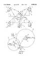
- FIG. 2illustrates a location method utilizing two circles of probability
- FIG. 3illustrates a location method utilizing three circles of probability
- FIG. 4illustrates a diagrammatic view of an angle of arrival system
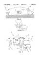
- FIG. 5illustrates a diagrammatic view of an application of the system of the present invention for locating the one of the locators 10;
- FIG. 5aillustrates a block diagram of the portable monitor or focus unit
- FIG. 6illustrates a block diagram of a locator
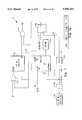
- FIG. 7illustrates a block diagram of the digital section of the locator
- FIG. 7aillustrates a diagram of the data field
- FIG. 8illustrates a block diagram of the code generator for the locator
- FIG. 9illustrates a block diagram of the RF section of the locator
- FIG. 9aillustrates an alternate body utilizing a phase lock loop for generation of the clock to the PN code generator
- FIG. 10illustrates a block diagram of the digital section of the receiver
- FIG. 11illustrates a block diagram of the complex sampler of the receiver
- FIG. 12illustrates a block diagram of the threshold comparator of the receiver
- FIG. 13illustrates a block diagram of the RAM storage portion of the receiver
- FIG. 14illustrates a block diagram of the RF section of the receiver
- FIG. 15illustrates a diagrammatic view of the data block that is transmitted
- FIG. 16illustrates a flow chart for the operation to scramble the data bits in the data block
- FIG. 17illustrates a flow chart for encrypting the data in the data block.
- a locator unit 10is provided which is a portable card like device that is disposed on an individual or is carried with an individual.
- the design of this cardcan be that utilizing a smart IC card or it can be similar to that utilized with respect to portable pager devices.
- the locator 10(not necessarily stationary) has an antenna 12 associated therewith.
- a plurality of receivers 14are disposed at various locations about the locator 10, it being noted that the locator 10 and the receivers 14 are stationary in the preferred and disclosed embodiment. Each of the receivers 14 has an antenna 18, which is operable to receive transmissions from the locator 10.
- the antenna 18can be utilized to communicate with a central monitor 20 that has an antenna 22, the antenna 22 operable to transmit information to the locator 10 and also receive and transmit information between the receivers 14 and the monitor 20 for transmitting information therebetween.
- a land line 24can be provided for allowing the communication to take place between the receivers 14 and monitor 20, this being for the purpose of relaying information received from the locator 10.
- the land line 24could be a wireless link.
- FIG. 2there is illustrated a diagrammatic view of a system utilizing only two receivers 14, this for a time of arrival system.
- the locator 10is disposed at a specific location relative to the two receivers, with it being located a farther distance from one receiver compared to the other.
- the closest receiverreceives the signal and can determine a relative time of arrival which will indicate that the receiver is along a loci of points to finding a first circle of probability 30.
- itis also along a second circle of probability 32 relative to a second receiver that is a farther distance away.
- the receiver associated with the circle 30will receive a signal first and the receiver 14 associated with the second circle 32 will receive the signal at a later time.
- there is a first actual true location 36 and another possible location 38this being the point at which the circles 30 and 32 intersect. Therefore, there will be an ambiguity with only using two receivers.
- FIG. 3there is illustrated a diagrammatic view wherein three receivers 14 are utilized.
- the closest receiverhas a first circle of probability 40 associated therewith, the second receiver has a circle of probability 42 associated therewith and a third receiver 14 has a circle of probability 44 associated therewith, these circles of probability 40-44 are in ascending size, with circle 40 being the smallest. Therefore, the receiver associated with receiver 40 will receive the signal first, the receiver associated with the circle 42 will receive the signal second and the receiver 14 associated with the third circle 44 will receive the signal last. As such, there is only a single location 46 at which the locator 10 can be found. Therefore, a minimum of three receivers are preferable, with more receivers providing a higher degree of resolution.
- receivers 14 and the locator 10communicate via an RF link.
- RF links in ideal situationsi.e., with no buildings, obstacles, etc. are very accurate transmission links.
- problemscan exist in the reception due to things such as multi-path. This can, therefore, result in a false reading as the signal taking a longer path and bouncing off of an object can be interpreted as being the main signal.
- the techniques utilized in the present inventionprovide for an elimination of the multi-path signal, although this is utilized in conventional techniques.
- the time of arrival from all locations along any given perfect circle about a receivermay not be the same due to different environmental parameters, etc. This could cause some errors in the location as the time or arrival system typically assumes that the transmission path through any media to the receiver is identical. For example, if a low lying cloud were disposed between one of the receivers and the locator, the transmission delay to that receiver would be different than the transmission delay to another one of the receivers, this not being accounted for in the receiver operation.
- FIG. 4there is illustrated a diagrammatic view of a system using an angle of arrival method.
- the angle of arrival methodtwo antennas 50 and 52 are illustrated.
- Energyarrives from a locator 10 at the antenna 50 along a path 54 and energy arrives at the antenna 52 along a path 56 from the same locator 10 when they are disposed at an angle ⁇ relative to the vertical.
- the antennasare disposed apart a distance of one wavelength ( ⁇ ). It can be seen that the energy along path 56 arrives at antenna 52 after the energy along path 54 arrives at the antenna 50. This results in a predetermined amount of delay. This delay can be measured and the angle therefor calculated. This gives a reference.
- this systemhas difficulty in determining whether the signal arrives in the front or the rear. This, of course, can be accounted for.
- the system of the present inventionutilizes a time of arrival method of detection.
- FIG. 5there is illustrated one application of the system of the present invention.
- One of the locators 10is disposed behind a wall 60.
- the locator 10operates in two separate modes, a high-power mode and a low power mode.
- the high-power modesufficient power is extracted from the battery (not shown) associated with the locator unit 10 to allow sufficient signal strength to be transmitted to antenna 18 on the receiver 14 illustrated in FIG. 5, it being known that other receivers are also provided that are not shown.
- this informationcan only be transmitted for a short time. Since the system of the present invention does not synchronize the various locator units, if various locator units are transmitting at the high power level at the same time, each of the receivers will receive signals at different times.
- the receiver 14can therefore discriminate between the various signals. Further, the signals are transmitted periodically.
- the locator unit 10goes into a low power mode and continues transmitting the alarm signals on a periodic basis. Therefore, security personnel can determine that an alarm has been set off and then go to the location determined by the monitor 20. Thereafter, a portable monitor 62 or focus unit is utilized by the security personnel to further define the location of the locating unit 10, which is typically carried by an individual. If, for example, the locator unit 10 were disposed behind a wall 60, as illustrated in FIG. 5, that was not visible by the security personnel, the approximate location within two to three feet would not be helpful. This can be the case where an individual is disposed, for example, in an elevator.
- the low power level signalcan be detected proximate to the locator unit 10 that is transmitting the alarm signal. This allows the high power system to have more inaccuracies in it while allowing the portable monitor 62 to provide the overall integrity required by a location system. By utilizing the low power mode, the transmission can occur for a much longer time without draining the battery.
- the portable monitor 62utilizes an angle of arrival system for locating an individual. This basically utilizes two identical receivers 66 and 68 and two antennas 70 and 72, respectively, which are disposed at a distance of one wavelength by the operating frequency of the locator unit 10. This allows the security personnel carrying the portable monitor 62 to further refine the location operation. The security personnel need only hold the unit such that the antennas 70 and 72 are parallel to the ground and then view a display 74 that will allow the security personnel to determine if the locator unit 10 is to the left or the right. Typically, there is a power level meter that determines how far away the individual is. The power level meter will indicate to the security personnel that they are walking in the wrong direction, i.e., that the locator unit 10 is behind them. This is typically not a problem as they are trying to determine if the locator unit is behind the wall.
- the locatoris comprised of a digital section 78 and an RF section 80 connected to the digital section for receiving data to be transmitted out as an alarm signal. This is transmitted out an RF port on the RF section to the antenna 12. Additionally, an FM pager decoder 82 is provided to provide a receive function at the locator 10. This is interfaced with an antenna 84, although the antenna 84 could be the same as the antenna 12. However, for the purposes of discussion, this is a separate antenna and, in fact, it may utilize a separate antenna.
- the FM pager decoder section 82is a conventional pager receiver that receives signals formatted in a Post Office Code Standardization Advisory Group (POCSAG) format which is conventional for pagers.
- the FM pager decoder 82is operable to receive conventional paging signals, decode the message and output it as data on a line 86 to the digital section 78.
- the pager decoder section 82is operable to allow information to be transmitted from the monitor 20 via antenna 22 to the locator 10.
- the pager decoder section 82allows the central station to transmit requests thereto or to download data thereto, as each pager decoder section 82 has associated therewith a unique ID. However, the primary discussion of the locator 10 will be with respect to the transmitted alarm signal.
- a transmit signal XMIT for test purposesis received on the input to the digital section 78 which is an input that forces the digital section 78 to transmit in a test mode.
- an alarm button switch 88is provided, which is connected to an alarm input on the digital section 78. This is a switch that, in the preferred embodiment, is a switch that, when depressed, causes the switch to be maintained in a closed position. Once the "seal" is broken, the switch is "latched”.
- An LED 90is provided for purposes of displaying the operation, i.e., that the switch 88 has been depressed and that the system is operating.
- a battery 92is provided which is connected to the input of the alarm button 88 and also for powering the digital section, RF section and the FM pager decoder 82.
- the digital sectionis operable to output the combination of data and code to a coded data input on the RF section 80.
- the microprocessoris a single-chip microprocessor (8748 or 8751 class), which serves as the overall controller for the locator 10. This device primarily is operable to detect alarm events by reading the status of an alarm bit on an alarm input line 98 that, when at a logic "high” initiates a sequence of events leading up to the transmission of a pseudonoise (PN) code burst.
- PNpseudonoise
- the microprocessor 96is also operable to indicate status by way of lighting the light emitting diode in various distinctive pattern, depending on what type of information is programmed into the system.
- a battery low conditioncould be indicated by a slow flashing
- a transmission of alarm signal indicated by a steady display of the LED and a fast periodic flashingcould indicate that the device is in working condition.
- the microprocessor 96is also operable to generate the alarm data.
- the datais stored in an Electrically Erasable Programmable Read Only Memory (EEPROM) 100 and is output on a line 102 to a P-type flip-flop 106 on the D-input thereof.
- EEPROMElectrically Erasable Programmable Read Only Memory
- a clock signalis generated via a main 16.384 MHz oscillator 104 which is divided by a factor of two in divider 108 to provide a frequency of 8.192 MHz on a line 109.
- Thisis input to a divide block 110 to divide the value on line 109 by a factor of 8192 to provide on an output line 112 a 1 kHz signal.
- Thisis input to the clock input of the D-type flip-flop 106 to clock the data on the D-input thereof at that rate to provide on the key output thereof the clock data signal to one input of an exclusive OR gate 114.
- the CPU 96provides an alarm output enable signal on a line 118 to the input of an OR gate 120, the other input connected to the XMIT signal indicating a transmit operation.
- OR gate 120The output of OR gate 120 is input to a PN code generator 122 on a start input.
- the PN code generator 122is clocked by the clock signal on line 109 to provide on the output thereof a PN code signal for input to the other input of the exclusive OR gate 114. Therefore, when the alarm signal is indicated, data is extracted from the EEPROM 100 and placed on the input to the flip-flop 106. This data is illustrated in FIG. 7a, which illustrates the manner in which the data is transmitted.
- the datais comprised of four fields, a data field, a user ID field, an alarm type field and a CRC field.
- the data fieldprovides the forty bits of data which is followed by a unique user ID associated with the locator 10.
- an alarm fielddetermines the alarm type, i.e., whether it is a real alarm, a test, a fire, etc. In the preferred embodiment, only one alarm type is provided for. However, multiple input switches could provided for indicating different types of alarms.
- the last fieldis a CRC field which provided cyclic redundancy check bits for the purpose of error.
- the data field illustrated in FIG. 7ais output in a serial manner such that the data field is continually output, it being sequential fields or periodic fields. This data is ORed with the exclusive OR 114 with the PN code to provide an output PND.
- the PN code generatoris essentially a counter 126 which provides for N-bits on a count output bus 128.
- the counter 126rolls over, it outputs a terminal count on a line 130, which is inverted by an inverter 132 and input to one input of an OR gate 134, the other input thereof input to an START signal.
- the output of the OR gate 134is input to an ENABLE input on the counter 126.
- the counter 126is docked by an 8.192 MHz signal on the line 109.
- the count output bus 128is input to the address input of a Programmable Read Only Memory (PROM) 136 that has stored therein bits of information in the form of words.
- PROMProgrammable Read Only Memory
- Each wordis eight bits wide with data bits D0-D7. However, in the preferred embodiment, only the DO bit is output on a line 138 to the input of a D-flip-flop 140. Flip-flop 140 is docked by the signal on line 109 with the Q-output thereof providing the PN code.
- FIG. 9there is illustrated a block diagram of the RF section 80.
- the output of the exclusive OR gate 114is input to the input of a mixer 142 which has the local oscillator (LO) input thereof connected to a 915 MHz oscillator 144.
- Thisprovides an up converter operation which mixes the base band data up to 915 MHz.
- Thisis input to a power amplifier 146, the output thereof passed through a bandpass filter 148 to provide the output signal.
- there is a level control input on the 915 MHz oscillator 144which is controlled by the digital section 78 to select the power level.
- the oscillator signal that drives the PN code generator 122is a 7.15 MHz oscillator 139 which has the output thereof input into a phase comparator 141 and also to the clock input of the PN code generator 122.
- the phase comparator 141has the output thereof input to a low pass filter 143, comprising the loop filter of a phase lock loop.
- the low pass filtercomprises the driving signal for a voltage controlled oscillator (VCO) 145, the output of which provides the carrier frequency of 915.2 MHz.
- VCOvoltage controlled oscillator
- the output of the VCO 145is also connected to the input of a divider block 147, which provides a division operation by a factor of 128.
- the output of the divider block 147is input to the other input of the phase comparator 141.
- Comparator 141, low pass filter 143, VCO 145 and divider block 147form a conventional phase lock loop. In this manner, the carrier is phase locked to the PN code generator 122.
- the receiver 14is comprised of a digital section and an RF section, the RF section receiving on the input a 915 MHz signal from the antenna 18.
- the RF section(not shown) is operable to output an IF signal containing the data which is input to a complex sampler 150.
- the complex sampler 150is operable to take the IF signal which has a nominal 16 MHz frequency, and digitize it at precisely four times the carrier frequency. When sampling at this rate, it is easy to show, that out of the group of four samples, the first and third represent the in phase "1-Phase" samples, while the second and fourth samples represent the quadrature phase "Q-Phase" samples.
- the third sampleis taken 180° out of phase with respect to the first sample and thus would be called a -I ("Negative I") sample. Accordingly, when combining the first and third samples, the third sample must be multiplied by -1 before combining it with the first sample; that is, adding it to the first sample. Similarly, the fourth sample must be multiplied by -1 before combining it with the second sample.
- the output of the complex sampler 150is input to a complex correlator 152, which is operable to match the digitized sample against a reference PN code supplied by the microprocessor and then seeks to determine a match.
- Two samples per chipare supplied by the complex correlator 152.
- an I, Q and magnitude sampleare output.
- the magnitude samplesare fed to a threshold comparator 158, while all three values are sent to a Random Access Memory (RAM) 156 for storage therein.
- the correlatorshould be at least 2 13 -1 (8195) chips (16,390 samples). This represents at 8 Mcps about a 32 ⁇ sec duration of time.
- This particular building block configuration of the complex correlator 152is a conventional technique.
- the complex correlatorhas the magnitude output thereof input to the threshold comparator 158.
- the threshold comparator 158is operable to compare the magnitude sample with a reference value ("threshold") supplied by a microprocessor 160.
- the output of the threshold comparator 158is input to the RXE input of the microprocessor 160. Both the threshold voltage and a release signal output from the microprocessor 160 for input to the threshold comparator 158.
- the microprocessor 160is also operable to generate the various address and data signals for input to the RAM 156.
- the clock signal on line 154is input to the clock input of a 16-bit counter 162 that is a free-running counter with no pre-set, lows or clear functions required. This, is the arbiter of time for each receiver.
- the 13 Least Significant Bits (LSBs) of the counter 162are used to generate a pulse once every millisecond.
- the counter 162also serves as an address generator during the collection of I, Q and magnitude data from the complex correlator 152. Each sample is stored in a location, the address of which is the time at which it was taken. This is useful because a more accurate time of arrival measurement can be obtained if the system tags random samples taken in the neighborhood of the sample which trigger the receipt of that indicator.
- a D-type flip-flop 166is provided, having a D-input thereof connected to the output of the counter 162. The clock input is clocked by the RXE signal output by the threshold comparator 158.
- the RXE signalis the "RECEIVE EVENT" signal that captures the time at which the receive event occurs.
- the Q-output of the flip-flop 166is input to the RX EVENT input of the microprocessor 160.
- the output of counter 162is buffered by a 14-bit AND gate 168 that provides an output when all 14 bits are logic "1s", which will happen once every millisecond. This signal is provided to an interrupt input on a microprocessor 160, this interrupt incrementing a counter internal to the microprocessor 160 for the purpose of keeping track of time.
- FIG. 11there is illustrated a block diagram of the complex sampler 150.
- the IF inputis buffered by a buffer 170 and input to the analog input of an A/D converter 172, the input thereof clocked by sampling clock 174 operating at a frequency of 65.536 MHz.
- Thisis a flash 6-bit A/D converter.
- the output of the A/D converter 172is fed to a 6-bit wide four stage shift register comprised of four flip-flops 176, 178, 180 and 182, the Q-output of flip-flop 176 connected to the D-input of flip-flop 178, the Q-output of flip-flop 178 connected to the D-input of flip-flop 180 and the Q-output of flip-flop 180 connected to the D-input of flip-flop 182.
- the output of flip-flop 176is connected to the positive input of a summing junction 184 and the Q-output of flip-flop 180 is connected to a negative input thereof to provide a subtraction operation.
- flip-flop 178is connected to a positive input of a summing junction 186, the negative input thereof connected to the Q-output of summing junction 182.
- the output of flip-flop 184is connected to the D-input of a flip-flop 190, and the output of summing junction 186 is connected to the D-input of a flip-flop 192.
- flip-flops 190 and 192clocked by 16 MHz clock signal on a line 194 that is generated by dividing the output of oscillator 174 by a factor of 4, with a divide block 196.
- the summing junction 184is operable to provide the combination of the first and third samples while the summing junction 186 is operable to combine the second and fourth samples.
- the flip-flop 190provides the "I” output and the flip-flop 192 provides the "P” output. It is important to note that the clock signal line 194 is exactly twice the clock rate of the PN chipping rate.
- FIG. 12there is illustrated a block diagram of the threshold comparator 158.
- the magnitude signalis input to a negative input of a summing junction 200, the positive input thereof connected to the threshold voltage from the microprocessor 160.
- the output of summing junction 200provides the sign only and is input to one input of an OR gate 202.
- the output of OR gate 202is input to the D-input of a flip-flop 204, the Q-output thereof providing an RXE output signal.
- the output of flip-flop 204is set back to the other input of the OR gate 202.
- Flip-flop 206is clocked by the clock signal line 194 with the clear input thereof connected to a release signal RELEASE from the microprocessor 160.
- the summing junction 200computes a difference between the magnitude and threshold which, assuming two's complement math, as long as the magnitude is less than the threshold, and this value is positive, the sign at the result is a logic "0".
- the OR gate 202 just prior to the flip-flop input having a "0" on a lower input and its outputtherefore tracks the sign of the output just computed. Assuming that the sign is "0”, Q remains at a logic "0", indicating that no receive event has occurred.
- the RAM 156is comprised of three individual memory chips, the address therein connected to an address bus 216 and the chip select inputs connected to three chip select lines 218.
- the data lines in each of the RAMs 210-214are provided by data lines 220, 222 and 224, respectively.
- the I-inputis connected to a data line 220 via a gate 226, the Q-input is connected to the data line 222 via a gate 228 and a MAG input is input to data line 224 via a gate 230.
- Gates 226-230are gated by a C/D* signal.
- data line 222is connected to the data bus 234 via a gate 238 and data line 224 is connected to the data bus 234 via a gate 240.
- Each of the data lines 220-224is a single bit data line with each of the RAMs 210-214 being a single data bit wide.
- the data bus 234is a 3-bit data bus for receiving the data bits from the data lines 220-224, respectively.
- the gates 236-240are clocked by the inverse of the signal C/D*.
- the C/D* signalis referred to as the "collect/not dump" line.
- the timer counterserves as an address generator via a gate 240.
- Each sampleis therefore uniquely addressed at a time at which it was taken.
- a gate 242that operates inverse to the gate 240 allows the address bus of the processor 160 to control the RAMs 210-214. Whenever the microprocessor 160 wants to examine the memory 210-214, the C/D line is taken "low".
- FIG. 14there is illustrated a block diagram of the RF section of the receiver 14.
- the 915 MH signal received by the antenna 18is input to a low noise amplifier section 250, the output thereof input to a bandpass filter 251, the output thereof input to a mixer 252.
- a local oscillator 254has the output thereof input to the local oscillator input of the mixer 252, the mixer 252 then operating as a down converter to downconvert the 915 MHZ signal to a frequency of 150 MHZ.
- Thisis input to a bandpass filter 256 to filter out the first IF.
- Thisis input through an amplifier 258 to a second mixer 260.
- the second mixerhas a local oscillator input connected to the output of a VCO 262 to downconvert the first IF signal to a frequency of 16 MHZ. If the output of the mixer 260 is input to a bandpass filter 264, the output thereof comprising a 16 MHZ IF signal. This is later downconverted in the final step to base band data by the A/D converter 172 and the complex sampler 150.
- the bandpass filters 251,256 and 264are provided for two reasons. First, the bandpass filter 251 is provided to reject out-of-band interference and avoid overload of the succeeding low noise amplifier and other amplifiers. Secondly, the bandpass filters are supplied to provide image rejection.
- the local oscillator 254is a sixth frequency local 254 oscillator at 765 MHZ with the VCO 262 operating in a nominal frequency of 134 MHZ. This, however, allows fine tuning over a range of +/ ⁇ 0.5 MHZ.
- An Automatic Gain Control (AGC) functionis provided by a power detector 270, which has the input thereof connected to the output and controls the various amplifiers in the chain.
- This systemis achieved by the user, when in a perilous situation by pressing the switch 88 to sound an alarm. As described above, this is sealed switch that, when the seal is broken, forces the alarm signal to be continuously output. This alarm signal is transmitted via the RF link to the receivers 14. This is done in a high power mode. This high power mode occurs on a periodic basis for a predetermined duration of time, at least 60 seconds. During this time period, the receivers 14 and the monitor 22 are operable to receive and decode the PN code sequences. Due to the PN code sequence, multiple signals can be received at substantially the same time and discriminated.
- the portable monitor 62for the purpose of doing a "find" location of the particular locator and the individual that set the alarm off. This allows the location to be determined within twenty to thirty feet. During this period of time, the locator has entered a low power mode such that the security official must be relatively close to the monitor. This is done for the purpose of conserving energy.
- the system of the present inventionwill be incorporated on a smart card with the use of various integrated circuits that are conventionally available. Therefore, only a certain size battery can be accommodated, thus minimizing the time that the alarm can be generated.
- the cardis activated once, the battery drained and then the card essentially disposed of and a new card issued. Therefore, the battery must be sized correctly and the power conserved in order to transmit a high integrity signal that can be received, located and actions taken.
- the data blockis comprised of three fields, a Sequence ID field, a User ID field and a CRC field.
- the Sequence IDis an eight bit field that is incremented by one count every time the system broadcasts the User ID/CRC fields. This field is included such that each receiver can uniquely describe the exact instance in time at which a particular data bit was received.
- the Sequence ID fieldbegins at "0" counts up to "255” and then rolls over to "0". This Sequence ID is repeated forever.
- the number of blocks of data transmitted per secondis a function of the bits-per-second rate of transmission divided by the number of bits in the data block, in this case 48 bits. In the preferred embodiment, data blocks are transmitted at 1000 bps, resulting in 21 data blocks being transmitted per second.
- the User IDis a 32 bit field which allows assignment of better than 4 billion unique IDs per a location, such as a college campus.
- the system administratormay wish to subdivide this field; in particular, the system administrator may wish to designate certain bits to have special meanings. For example, he could designate the first or the last two bits as an "alarm" type.
- the alarm type fieldwould then be interpreted as a number between 0-3 with the number "0" being a built in test value which would be ignored. This would only be used by test technicians.
- An alarm type of "1”would be a time coordination message, which would be an alarm type that is utilized by the monitor segment to broadcast time coordination messages.
- An alarm type of "2"would be a subscriber alarm. This is the alarm type used by every victims locator.
- the CRC fieldis an eight bit field that is used to verify the integrity of the transmission.
- the frame syncis obtained by exhaustively examining all possible positions for the CRC field and finding the position at which the CRC properly checks. By examining all bits in both a positive-true and negative-true fashion, this would resolve any bit encoding ambiguity.
- the firstis to scramble the User ID bits
- the secondis to encrypt the User ID bits.
- the User ID bitsare encrypted or scrambled, but it should be understood that the entire data block could be encrypted in some manner.
- the Sequence ID fieldis always broadcast with no encryption or scrambling.
- the User IDis sent in a fashion that is either scrambled or encrypted or both. This allows the user to recognize the data block without a block decryption device or a block unscrambler.
- FIG. 16there is illustrated a flow chart of the data scrambling operation. This is initiated at a block 300 and then proceeds to a function block 302 wherein the lowest five bits from the Sequence ID are extracted. This essentially takes the Sequence ID to a modulo 32 base. The program then flows to a function block 304 which then interprets this as a number from 0 to 31 and assigns this a number "n”. The program then flows to a function block 306 to broadcast the nth bit first and then flows to a function block 308 to increase the number "n" by the value of one and then broadcasts the next bit, as indicated by function block 310. The program loops back along a path 312 until all 32 bits in the User ID are broadcast.
- the programflows from a decision block 314 to a decision block 316 to determine if a new data block has been generated. If so, the program flows along a "Y" path back to the input of the function block 302. Until the new block has been received, the program will flow along a "N" path back to the input of the decision block 316.
- FIG. 17there is illustrated a flow chart for the encryption operation, which is initiated at a block 320 and then flows to a function block 322.
- the Sequence IDis received and then the program flows to a function block 324 to interpret the Sequence ID as an 8 bit field.
- the 8 bit fieldis then rotated by 2 bits, as indicated by a function block 326, and then this value XORed with bits 8-15 of the User ID as indicated by the function block 328 to provide the first eight encrypted bits for the data field.
- the Sequence IDis rotated by 2 bits, as indicated by function block 330, and then XORed with bits 16-23 of the User ID, as indicated by a function block 332.
- the programthen flows to a function block 334 to rotate the Sequence ID by 2 bits and then to function block 336 to XORed this value with bits 24-31 of the User ID. To decrypt this data, it is only necessary to perform the reverse operation.
Landscapes
- Business, Economics & Management (AREA)
- Emergency Management (AREA)
- Physics & Mathematics (AREA)
- General Physics & Mathematics (AREA)
- Engineering & Computer Science (AREA)
- Computer Security & Cryptography (AREA)
- Mobile Radio Communication Systems (AREA)
Abstract
Description
Claims (13)
Priority Applications (4)
| Application Number | Priority Date | Filing Date | Title |
|---|---|---|---|
| US08/442,469US5596313A (en) | 1995-05-16 | 1995-05-16 | Dual power security location system |
| AU58574/96AAU5857496A (en) | 1995-05-16 | 1996-05-13 | Dual power level security location system |
| EP96920187AEP0830659A4 (en) | 1995-05-16 | 1996-05-13 | Dual power level security location system |
| PCT/US1996/006776WO1996036951A1 (en) | 1995-05-16 | 1996-05-13 | Dual power level security location system |
Applications Claiming Priority (1)
| Application Number | Priority Date | Filing Date | Title |
|---|---|---|---|
| US08/442,469US5596313A (en) | 1995-05-16 | 1995-05-16 | Dual power security location system |
Publications (1)
| Publication Number | Publication Date |
|---|---|
| US5596313Atrue US5596313A (en) | 1997-01-21 |
Family
ID=23756906
Family Applications (1)
| Application Number | Title | Priority Date | Filing Date |
|---|---|---|---|
| US08/442,469Expired - Fee RelatedUS5596313A (en) | 1995-05-16 | 1995-05-16 | Dual power security location system |
Country Status (4)
| Country | Link |
|---|---|
| US (1) | US5596313A (en) |
| EP (1) | EP0830659A4 (en) |
| AU (1) | AU5857496A (en) |
| WO (1) | WO1996036951A1 (en) |
Cited By (50)
| Publication number | Priority date | Publication date | Assignee | Title |
|---|---|---|---|---|
| US5719584A (en)* | 1996-09-03 | 1998-02-17 | Harris Corporation | System and method for determining the geolocation of a transmitter |
| US5828306A (en)* | 1996-04-15 | 1998-10-27 | Curran; Brendan Joseph | Location detector and monitor and method of using the same |
| WO1999062039A1 (en)* | 1998-05-27 | 1999-12-02 | Sarnoff Corporation | Locating system and method employing radio frequency tags |
| US6034622A (en)* | 1995-08-18 | 2000-03-07 | Robert A. Levine | Location monitoring via implanted radio transmitter |
| WO2000023956A1 (en)* | 1998-10-22 | 2000-04-27 | University Of Maryland | Method and system for providing location dependent and personal identification information to a public safety answering point |
| US6075443A (en)* | 1998-07-31 | 2000-06-13 | Sarnoff Corporation | Wireless tether |
| US6188496B1 (en)* | 1997-11-25 | 2001-02-13 | International Business Machines Corporation | Wireless communication system |
| US6222487B1 (en)* | 1998-07-02 | 2001-04-24 | Telefonaktiebolaget Lm Ericsson, (Publ), | System and method for measurement |
| WO2002031787A1 (en)* | 2000-10-12 | 2002-04-18 | Safetzone Technologies Corporation | System for real-time location of people in a fixed environment |
| US6437683B1 (en)* | 1999-01-08 | 2002-08-20 | Leopold Kostal Gmbh & Co. | Keyless security entry control method for motor vehicles |
| US20020186691A1 (en)* | 2000-04-17 | 2002-12-12 | Steven Bristow | Software and protocol structure for an automated user notification system |
| US20030050075A1 (en)* | 2001-08-15 | 2003-03-13 | Jayanthi Rangarajan | System and method for determining a location relevant to a communication device and/or its associated user |
| US20030146835A1 (en)* | 2000-03-31 | 2003-08-07 | Ge Medical Systems Information Technologies, Inc. | Object location monitoring within buildings |
| US20030206115A1 (en)* | 2002-05-01 | 2003-11-06 | John Krumm | Location measurement process for radio-frequency badges |
| US6664896B2 (en)* | 2001-10-11 | 2003-12-16 | Mcdonald Jill Elizabeth | Article locating device using position location |
| US6700493B1 (en) | 1996-12-02 | 2004-03-02 | William A. Robinson | Method, apparatus and system for tracking, locating and monitoring an object or individual |
| US6735477B2 (en) | 2001-07-09 | 2004-05-11 | Robert A. Levine | Internal monitoring system with detection of food intake |
| US20040252023A1 (en)* | 2001-09-27 | 2004-12-16 | Xydis Thomas G. | Monitoring method and system |
| US20040252015A1 (en)* | 2001-09-25 | 2004-12-16 | Natan Galperin | Multiple broadcasting tag and monitoring systems including the same |
| US6850734B1 (en)* | 1994-12-23 | 2005-02-01 | Itt Manufacturing Enterprises, Inc. | Position enhanced communication system including system for embedding CDMA navigation beacons under the communications signals of a wireless communication system |
| SG108813A1 (en)* | 1999-03-19 | 2005-02-28 | Citibank Na | System and method for validating and measuring effectiveness of information security programs |
| US20050088301A1 (en)* | 2003-10-14 | 2005-04-28 | Paul Abbruscato | Direction finder and locator |
| US6920315B1 (en)* | 2000-03-22 | 2005-07-19 | Ericsson Inc. | Multiple antenna impedance optimization |
| US20050282558A1 (en)* | 2004-06-21 | 2005-12-22 | Korea Electrotechnology Research Institute | System and method for asynchronous wireless positioning by ordered transmission |
| US20060055552A1 (en)* | 2004-08-26 | 2006-03-16 | Chung Kevin K | RFID device for object monitoring, locating, and tracking |
| US20060102731A1 (en)* | 2004-11-17 | 2006-05-18 | Mueller Carl J | Thermostat control system providing power saving transmissions |
| WO2006079844A1 (en)* | 2005-01-31 | 2006-08-03 | Albert Hall Meetings Limited | An audience response system |
| WO2006082519A1 (en)* | 2005-02-03 | 2006-08-10 | Santamaria Arnau, Joan | Emergency device |
| US20060223566A1 (en)* | 2005-04-04 | 2006-10-05 | Research In Motion Limited | Determining a target transmit power of a wireless transmission according to security requirements |
| US20070001854A1 (en)* | 2004-08-26 | 2007-01-04 | Chung Kevin K | Object monitoring, locating, and tracking method employing RFID devices |
| US20070013519A1 (en)* | 2004-08-26 | 2007-01-18 | Chung Kevin K | Object monitoring, locating, and tracking system employing RFID devices |
| US20070268138A1 (en)* | 2004-08-26 | 2007-11-22 | Chung Kevin K | Object monitoring, locating, and tracking system and method employing rfid devices |
| US20080012760A1 (en)* | 2006-07-14 | 2008-01-17 | Remotemdx | Remote tracking device and a system and method for two-way voice communication between the device and a monitoring center |
| US20080096521A1 (en)* | 1998-03-19 | 2008-04-24 | Securealert, Inc. | Emergency phone with single button activation |
| US20080157983A1 (en)* | 2006-10-17 | 2008-07-03 | Designlink, Llc | Remotely Operable Game Call or Monitoring Apparatus |
| US20080311943A1 (en)* | 2007-06-15 | 2008-12-18 | Jeffrey Earl | Audience Response And Communication System and Method |
| US20090201169A1 (en)* | 2008-02-07 | 2009-08-13 | Mark Iv Industries Corp. | Real-Time Location Systems and Methods |
| US7737841B2 (en) | 2006-07-14 | 2010-06-15 | Remotemdx | Alarm and alarm management system for remote tracking devices |
| US7804412B2 (en) | 2005-08-10 | 2010-09-28 | Securealert, Inc. | Remote tracking and communication device |
| US20110072132A1 (en)* | 2009-09-21 | 2011-03-24 | Checkpoint Systems, Inc. | Retail Product Tracking System, Method, and Apparatus |
| US20110068921A1 (en)* | 2009-09-21 | 2011-03-24 | Checkpoint Systems, Inc. | configurable monitoring device |
| US20110084840A1 (en)* | 2009-10-02 | 2011-04-14 | Checkpoint Systems, Inc. | Key Device for Monitoring Systems |
| US7936262B2 (en) | 2006-07-14 | 2011-05-03 | Securealert, Inc. | Remote tracking system with a dedicated monitoring center |
| US8174383B1 (en) | 2004-08-26 | 2012-05-08 | Avante International Technology, Inc. | System and method for operating a synchronized wireless network |
| US8232876B2 (en) | 2008-03-07 | 2012-07-31 | Securealert, Inc. | System and method for monitoring individuals using a beacon and intelligent remote tracking device |
| US20130151143A1 (en)* | 2008-08-22 | 2013-06-13 | Htc Corporation | Method and apparatus for reminding calendar schedule and recording medium |
| US8514070B2 (en) | 2010-04-07 | 2013-08-20 | Securealert, Inc. | Tracking device incorporating enhanced security mounting strap |
| US8717174B2 (en) | 2010-09-07 | 2014-05-06 | 3M Innovative Properties Company | Monitoring apparatus for a tag having an engaged and a non-engaged mode |
| WO2015023802A1 (en)* | 2013-08-13 | 2015-02-19 | Duke University | Systems and methods for using time of flight measurements for imaging target objects |
| US10878686B1 (en) | 2018-03-26 | 2020-12-29 | Badge Messenger Inc. | Badge holder with one touch communication |
Families Citing this family (2)
| Publication number | Priority date | Publication date | Assignee | Title |
|---|---|---|---|---|
| EP1766882A2 (en)* | 2004-07-15 | 2007-03-28 | Hunter Douglas Inc. | System and method for adaptively controlling a network of distributed devices |
| CN104541571B (en)* | 2012-07-17 | 2019-04-23 | 中兴通讯股份有限公司 | Data transmission method and device |
Citations (44)
| Publication number | Priority date | Publication date | Assignee | Title |
|---|---|---|---|---|
| US4234874A (en)* | 1978-11-08 | 1980-11-18 | Inventional/Security Development Corp. | Alarm system and method thereof |
| US4275385A (en)* | 1979-08-13 | 1981-06-23 | Bell Telephone Laboratories, Incorporated | Infrared personnel locator system |
| US4369426A (en)* | 1979-03-29 | 1983-01-18 | Repa Feinstanzwerk Gmbh | Emergency distress signal system for motor vehicles |
| US4446454A (en)* | 1981-01-21 | 1984-05-01 | Pyle Ronald E | Home security system |
| US4511887A (en)* | 1981-09-14 | 1985-04-16 | Radionics, Inc. | Long range wireless alarm monitoring system |
| US4523184A (en)* | 1982-09-30 | 1985-06-11 | Sentrol, Inc. | Supervised wireless security system |
| US4559526A (en)* | 1982-06-29 | 1985-12-17 | Secom Co., Ltd. | Security alarm system |
| US4593273A (en)* | 1984-03-16 | 1986-06-03 | Narcisse Bernadine O | Out-of-range personnel monitor and alarm |
| US4598275A (en)* | 1983-05-09 | 1986-07-01 | Marc Industries Incorporated | Movement monitor |
| US4606073A (en)* | 1979-02-21 | 1986-08-12 | Moore Alfred Z | Assistance summoning system |
| US4647914A (en)* | 1984-07-20 | 1987-03-03 | Mitsubishi Electric America, Inc. | Security apparatus and system |
| US4651157A (en)* | 1985-05-07 | 1987-03-17 | Mets, Inc. | Security monitoring and tracking system |
| US4661804A (en)* | 1982-09-30 | 1987-04-28 | Sentrol, Inc. | Supervised wireless security system |
| US4670739A (en)* | 1984-12-14 | 1987-06-02 | Kelly Jr Lawrence R | Communication system especially useful as an incident location reporting security system |
| US4682155A (en)* | 1986-01-13 | 1987-07-21 | Central Security Mfg. Corp. | Personnel security system |
| US4694282A (en)* | 1985-01-31 | 1987-09-15 | Kabushiki Kaisha Toshiba | Security monitoring system |
| US4737771A (en)* | 1986-07-23 | 1988-04-12 | Emhart Industries, Inc. | Security system with interference detection |
| US4764757A (en)* | 1987-03-12 | 1988-08-16 | Demarco Frank G | Security detection and location system with independent local alarm and communications circuits |
| US4792804A (en)* | 1986-05-02 | 1988-12-20 | Dei-Dispositivi Elettronici Industriali Di Rubechini Roberto | Apparatus for detecting a body in motion on the ground of a protected area |
| US4853692A (en)* | 1987-12-07 | 1989-08-01 | Wolk Barry M | Infant security system |
| US4864277A (en)* | 1984-02-24 | 1989-09-05 | Goodman David J | Radio alarm system |
| US4884067A (en)* | 1987-08-13 | 1989-11-28 | Talkie Tooter (Canada) Ltd. | Motion and position sensing alarm |
| US4908627A (en)* | 1985-06-14 | 1990-03-13 | Santos James P | Monitoring, ranging and locating devices |
| US4910493A (en)* | 1988-07-11 | 1990-03-20 | Automated Security (Holdings) Pcl | Security systems |
| US4918425A (en)* | 1988-07-25 | 1990-04-17 | Daniel E. Ely | Monitoring and locating system for an object attached to a transponder monitored by a base station having an associated ID code |
| US4952928A (en)* | 1988-08-29 | 1990-08-28 | B. I. Incorporated | Adaptable electronic monitoring and identification system |
| US4998095A (en)* | 1989-10-19 | 1991-03-05 | Specific Cruise Systems, Inc. | Emergency transmitter system |
| US5021794A (en)* | 1989-08-15 | 1991-06-04 | Lawrence Robert A | Personal emergency locator system |
| US5025247A (en)* | 1990-04-09 | 1991-06-18 | Banks James C | Portable emergency alert system |
| US5045839A (en)* | 1990-03-08 | 1991-09-03 | Rand G. Ellis | Personnel monitoring man-down alarm and location system |
| US5070320A (en)* | 1989-06-12 | 1991-12-03 | Ralph Ramono | Alarm system |
| US5115223A (en)* | 1990-09-20 | 1992-05-19 | Moody Thomas O | Personnel location monitoring system and method |
| US5196825A (en)* | 1991-12-16 | 1993-03-23 | Young James T | Personal security apparatus |
| US5200735A (en)* | 1989-07-11 | 1993-04-06 | Hines Thomas N | Weather protected portable security system for in-field use |
| US5204670A (en)* | 1988-08-29 | 1993-04-20 | B. I. Incorporated | Adaptable electric monitoring and identification system |
| US5218344A (en)* | 1991-07-31 | 1993-06-08 | Ricketts James G | Method and system for monitoring personnel |
| US5223816A (en)* | 1992-01-17 | 1993-06-29 | Levinson Samuel H | Security and communication system with location detection |
| US5225809A (en)* | 1990-12-24 | 1993-07-06 | Mayday U.S.A. Inc. | Personal security system and apparatus therefor |
| US5235320A (en)* | 1989-06-12 | 1993-08-10 | Ralph Romano | Alarm system |
| US5257007A (en)* | 1991-10-01 | 1993-10-26 | M-Tec Corporation | Portable security system |
| US5278539A (en)* | 1992-02-11 | 1994-01-11 | Bell Atlantic Network Services, Inc. | Alerting and warning system |
| US5283549A (en)* | 1991-05-31 | 1994-02-01 | Intellitech Industries, Inc. | Infrared sentry with voiced radio dispatched alarms |
| US5289163A (en)* | 1992-09-16 | 1994-02-22 | Perez Carla D | Child position monitoring and locating device |
| US5311185A (en)* | 1992-08-31 | 1994-05-10 | Hochstein Peter A | Supervised personnel monitoring system |
Family Cites Families (3)
| Publication number | Priority date | Publication date | Assignee | Title |
|---|---|---|---|---|
| US3986119A (en)* | 1973-12-28 | 1976-10-12 | International Business Machines Corporation | Emergency communication system |
| US4814751A (en)* | 1987-02-27 | 1989-03-21 | Wildlife Materials, Inc. | Patient tracking system |
| GB8906213D0 (en)* | 1989-03-17 | 1989-05-04 | Advanced Technology Ind Ltd | Locating system |
- 1995
- 1995-05-16USUS08/442,469patent/US5596313A/ennot_activeExpired - Fee Related
- 1996
- 1996-05-13AUAU58574/96Apatent/AU5857496A/ennot_activeAbandoned
- 1996-05-13WOPCT/US1996/006776patent/WO1996036951A1/ennot_activeApplication Discontinuation
- 1996-05-13EPEP96920187Apatent/EP0830659A4/ennot_activeWithdrawn
Patent Citations (45)
| Publication number | Priority date | Publication date | Assignee | Title |
|---|---|---|---|---|
| US4234874A (en)* | 1978-11-08 | 1980-11-18 | Inventional/Security Development Corp. | Alarm system and method thereof |
| US4606073A (en)* | 1979-02-21 | 1986-08-12 | Moore Alfred Z | Assistance summoning system |
| US4369426A (en)* | 1979-03-29 | 1983-01-18 | Repa Feinstanzwerk Gmbh | Emergency distress signal system for motor vehicles |
| US4275385A (en)* | 1979-08-13 | 1981-06-23 | Bell Telephone Laboratories, Incorporated | Infrared personnel locator system |
| US4446454A (en)* | 1981-01-21 | 1984-05-01 | Pyle Ronald E | Home security system |
| US4511887A (en)* | 1981-09-14 | 1985-04-16 | Radionics, Inc. | Long range wireless alarm monitoring system |
| US4559526A (en)* | 1982-06-29 | 1985-12-17 | Secom Co., Ltd. | Security alarm system |
| US4661804A (en)* | 1982-09-30 | 1987-04-28 | Sentrol, Inc. | Supervised wireless security system |
| US4523184A (en)* | 1982-09-30 | 1985-06-11 | Sentrol, Inc. | Supervised wireless security system |
| US4598275A (en)* | 1983-05-09 | 1986-07-01 | Marc Industries Incorporated | Movement monitor |
| US4864277A (en)* | 1984-02-24 | 1989-09-05 | Goodman David J | Radio alarm system |
| US4593273A (en)* | 1984-03-16 | 1986-06-03 | Narcisse Bernadine O | Out-of-range personnel monitor and alarm |
| US4647914A (en)* | 1984-07-20 | 1987-03-03 | Mitsubishi Electric America, Inc. | Security apparatus and system |
| US4670739A (en)* | 1984-12-14 | 1987-06-02 | Kelly Jr Lawrence R | Communication system especially useful as an incident location reporting security system |
| US4694282A (en)* | 1985-01-31 | 1987-09-15 | Kabushiki Kaisha Toshiba | Security monitoring system |
| US4651157A (en)* | 1985-05-07 | 1987-03-17 | Mets, Inc. | Security monitoring and tracking system |
| US4908627A (en)* | 1985-06-14 | 1990-03-13 | Santos James P | Monitoring, ranging and locating devices |
| US4682155A (en)* | 1986-01-13 | 1987-07-21 | Central Security Mfg. Corp. | Personnel security system |
| US4792804A (en)* | 1986-05-02 | 1988-12-20 | Dei-Dispositivi Elettronici Industriali Di Rubechini Roberto | Apparatus for detecting a body in motion on the ground of a protected area |
| US4737771A (en)* | 1986-07-23 | 1988-04-12 | Emhart Industries, Inc. | Security system with interference detection |
| US4764757A (en)* | 1987-03-12 | 1988-08-16 | Demarco Frank G | Security detection and location system with independent local alarm and communications circuits |
| US4884067A (en)* | 1987-08-13 | 1989-11-28 | Talkie Tooter (Canada) Ltd. | Motion and position sensing alarm |
| US4978946A (en)* | 1987-08-13 | 1990-12-18 | Talkie Tooter (Canada) Ltd. | Personal security communication system |
| US4853692A (en)* | 1987-12-07 | 1989-08-01 | Wolk Barry M | Infant security system |
| US4910493A (en)* | 1988-07-11 | 1990-03-20 | Automated Security (Holdings) Pcl | Security systems |
| US4918425A (en)* | 1988-07-25 | 1990-04-17 | Daniel E. Ely | Monitoring and locating system for an object attached to a transponder monitored by a base station having an associated ID code |
| US4952928A (en)* | 1988-08-29 | 1990-08-28 | B. I. Incorporated | Adaptable electronic monitoring and identification system |
| US5204670A (en)* | 1988-08-29 | 1993-04-20 | B. I. Incorporated | Adaptable electric monitoring and identification system |
| US5070320A (en)* | 1989-06-12 | 1991-12-03 | Ralph Ramono | Alarm system |
| US5235320A (en)* | 1989-06-12 | 1993-08-10 | Ralph Romano | Alarm system |
| US5200735A (en)* | 1989-07-11 | 1993-04-06 | Hines Thomas N | Weather protected portable security system for in-field use |
| US5021794A (en)* | 1989-08-15 | 1991-06-04 | Lawrence Robert A | Personal emergency locator system |
| US4998095A (en)* | 1989-10-19 | 1991-03-05 | Specific Cruise Systems, Inc. | Emergency transmitter system |
| US5045839A (en)* | 1990-03-08 | 1991-09-03 | Rand G. Ellis | Personnel monitoring man-down alarm and location system |
| US5025247A (en)* | 1990-04-09 | 1991-06-18 | Banks James C | Portable emergency alert system |
| US5115223A (en)* | 1990-09-20 | 1992-05-19 | Moody Thomas O | Personnel location monitoring system and method |
| US5225809A (en)* | 1990-12-24 | 1993-07-06 | Mayday U.S.A. Inc. | Personal security system and apparatus therefor |
| US5283549A (en)* | 1991-05-31 | 1994-02-01 | Intellitech Industries, Inc. | Infrared sentry with voiced radio dispatched alarms |
| US5218344A (en)* | 1991-07-31 | 1993-06-08 | Ricketts James G | Method and system for monitoring personnel |
| US5257007A (en)* | 1991-10-01 | 1993-10-26 | M-Tec Corporation | Portable security system |
| US5196825A (en)* | 1991-12-16 | 1993-03-23 | Young James T | Personal security apparatus |
| US5223816A (en)* | 1992-01-17 | 1993-06-29 | Levinson Samuel H | Security and communication system with location detection |
| US5278539A (en)* | 1992-02-11 | 1994-01-11 | Bell Atlantic Network Services, Inc. | Alerting and warning system |
| US5311185A (en)* | 1992-08-31 | 1994-05-10 | Hochstein Peter A | Supervised personnel monitoring system |
| US5289163A (en)* | 1992-09-16 | 1994-02-22 | Perez Carla D | Child position monitoring and locating device |
Cited By (89)
| Publication number | Priority date | Publication date | Assignee | Title |
|---|---|---|---|---|
| US6850734B1 (en)* | 1994-12-23 | 2005-02-01 | Itt Manufacturing Enterprises, Inc. | Position enhanced communication system including system for embedding CDMA navigation beacons under the communications signals of a wireless communication system |
| US6334073B1 (en)* | 1995-08-18 | 2001-12-25 | Robert A. Levine | Internal monitoring and behavior control system |
| US6034622A (en)* | 1995-08-18 | 2000-03-07 | Robert A. Levine | Location monitoring via implanted radio transmitter |
| US6154676A (en)* | 1995-08-18 | 2000-11-28 | Levine; Robert A. | Internal monitoring and behavior control system |
| US5828306A (en)* | 1996-04-15 | 1998-10-27 | Curran; Brendan Joseph | Location detector and monitor and method of using the same |
| US5719584A (en)* | 1996-09-03 | 1998-02-17 | Harris Corporation | System and method for determining the geolocation of a transmitter |
| US6700493B1 (en) | 1996-12-02 | 2004-03-02 | William A. Robinson | Method, apparatus and system for tracking, locating and monitoring an object or individual |
| US6188496B1 (en)* | 1997-11-25 | 2001-02-13 | International Business Machines Corporation | Wireless communication system |
| US20080096521A1 (en)* | 1998-03-19 | 2008-04-24 | Securealert, Inc. | Emergency phone with single button activation |
| US6040774A (en)* | 1998-05-27 | 2000-03-21 | Sarnoff Corporation | Locating system and method employing radio frequency tags |
| WO1999062039A1 (en)* | 1998-05-27 | 1999-12-02 | Sarnoff Corporation | Locating system and method employing radio frequency tags |
| US6222487B1 (en)* | 1998-07-02 | 2001-04-24 | Telefonaktiebolaget Lm Ericsson, (Publ), | System and method for measurement |
| US6075443A (en)* | 1998-07-31 | 2000-06-13 | Sarnoff Corporation | Wireless tether |
| WO2000023956A1 (en)* | 1998-10-22 | 2000-04-27 | University Of Maryland | Method and system for providing location dependent and personal identification information to a public safety answering point |
| US6437683B1 (en)* | 1999-01-08 | 2002-08-20 | Leopold Kostal Gmbh & Co. | Keyless security entry control method for motor vehicles |
| SG108813A1 (en)* | 1999-03-19 | 2005-02-28 | Citibank Na | System and method for validating and measuring effectiveness of information security programs |
| US6920315B1 (en)* | 2000-03-22 | 2005-07-19 | Ericsson Inc. | Multiple antenna impedance optimization |
| US7038584B2 (en)* | 2000-03-31 | 2006-05-02 | Ge Medical Systems Information Technologies, Inc. | Object location monitoring within buildings |
| US20030146835A1 (en)* | 2000-03-31 | 2003-08-07 | Ge Medical Systems Information Technologies, Inc. | Object location monitoring within buildings |
| US20020186691A1 (en)* | 2000-04-17 | 2002-12-12 | Steven Bristow | Software and protocol structure for an automated user notification system |
| US7489921B2 (en)* | 2000-04-17 | 2009-02-10 | Decarta Inc. | Software and protocol structure for an automated user notification system |
| US7310509B2 (en)* | 2000-04-17 | 2007-12-18 | Decarta Inc. | Software and protocol structure for an automated user notification system |
| US20050197106A1 (en)* | 2000-04-17 | 2005-09-08 | Telcontar | Software and protocol structure for an automated user notification system |
| US6424264B1 (en) | 2000-10-12 | 2002-07-23 | Safetzone Technologies Corporation | System for real-time location of people in a fixed environment |
| WO2002031787A1 (en)* | 2000-10-12 | 2002-04-18 | Safetzone Technologies Corporation | System for real-time location of people in a fixed environment |
| US6735477B2 (en) | 2001-07-09 | 2004-05-11 | Robert A. Levine | Internal monitoring system with detection of food intake |
| US6757544B2 (en)* | 2001-08-15 | 2004-06-29 | Motorola, Inc. | System and method for determining a location relevant to a communication device and/or its associated user |
| US20030050075A1 (en)* | 2001-08-15 | 2003-03-13 | Jayanthi Rangarajan | System and method for determining a location relevant to a communication device and/or its associated user |
| US7317377B2 (en) | 2001-09-25 | 2008-01-08 | Dmatek, Ltd. | Multiple broadcasting tag and monitoring systems including the same |
| US20040252015A1 (en)* | 2001-09-25 | 2004-12-16 | Natan Galperin | Multiple broadcasting tag and monitoring systems including the same |
| US6894612B2 (en) | 2001-09-27 | 2005-05-17 | Audio Alert, Llc | Monitoring method and system |
| US20040252023A1 (en)* | 2001-09-27 | 2004-12-16 | Xydis Thomas G. | Monitoring method and system |
| US6664896B2 (en)* | 2001-10-11 | 2003-12-16 | Mcdonald Jill Elizabeth | Article locating device using position location |
| US20050270170A1 (en)* | 2002-05-01 | 2005-12-08 | Microsoft Corporation | Location measurement process for radio-frequency badges |
| US20030206115A1 (en)* | 2002-05-01 | 2003-11-06 | John Krumm | Location measurement process for radio-frequency badges |
| US6993592B2 (en)* | 2002-05-01 | 2006-01-31 | Microsoft Corporation | Location measurement process for radio-frequency badges |
| US20050088301A1 (en)* | 2003-10-14 | 2005-04-28 | Paul Abbruscato | Direction finder and locator |
| US7148802B2 (en)* | 2003-10-14 | 2006-12-12 | Paul Abbruscato | Direction finder and locator |
| US20050282558A1 (en)* | 2004-06-21 | 2005-12-22 | Korea Electrotechnology Research Institute | System and method for asynchronous wireless positioning by ordered transmission |
| US7411551B2 (en)* | 2004-06-21 | 2008-08-12 | Korea Electrotechnology Research Institute | System and method for asynchronous wireless positioning by ordered transmission |
| US8174383B1 (en) | 2004-08-26 | 2012-05-08 | Avante International Technology, Inc. | System and method for operating a synchronized wireless network |
| US20070013519A1 (en)* | 2004-08-26 | 2007-01-18 | Chung Kevin K | Object monitoring, locating, and tracking system employing RFID devices |
| US20070268138A1 (en)* | 2004-08-26 | 2007-11-22 | Chung Kevin K | Object monitoring, locating, and tracking system and method employing rfid devices |
| US7839289B2 (en) | 2004-08-26 | 2010-11-23 | Avante International Technology, Inc. | Object monitoring, locating, and tracking system and method employing RFID devices |
| US8686861B2 (en) | 2004-08-26 | 2014-04-01 | Panasec Corporation | Object monitoring, locating, and tracking system and method employing RFID devices |
| US7319397B2 (en) | 2004-08-26 | 2008-01-15 | Avante International Technology, Inc. | RFID device for object monitoring, locating, and tracking |
| US7423535B2 (en) | 2004-08-26 | 2008-09-09 | Avante International Technology, Inc. | Object monitoring, locating, and tracking method employing RFID devices |
| US7342497B2 (en) | 2004-08-26 | 2008-03-11 | Avante International Technology, Inc | Object monitoring, locating, and tracking system employing RFID devices |
| US20060055552A1 (en)* | 2004-08-26 | 2006-03-16 | Chung Kevin K | RFID device for object monitoring, locating, and tracking |
| US20070001854A1 (en)* | 2004-08-26 | 2007-01-04 | Chung Kevin K | Object monitoring, locating, and tracking method employing RFID devices |
| US20100164710A1 (en)* | 2004-08-26 | 2010-07-01 | Kevin Kwong-Tai Chung | Object monitoring, locating, and tracking system and method employing rfid devices |
| US20090236433A1 (en)* | 2004-11-17 | 2009-09-24 | Mueller Carl J | Thermostat control system providing power saving transmissions |
| US7537171B2 (en)* | 2004-11-17 | 2009-05-26 | Emerson Electric Co. | Thermostat control system providing power saving transmissions |
| US20060102731A1 (en)* | 2004-11-17 | 2006-05-18 | Mueller Carl J | Thermostat control system providing power saving transmissions |
| WO2006079844A1 (en)* | 2005-01-31 | 2006-08-03 | Albert Hall Meetings Limited | An audience response system |
| WO2006082519A1 (en)* | 2005-02-03 | 2006-08-10 | Santamaria Arnau, Joan | Emergency device |
| US7477913B2 (en)* | 2005-04-04 | 2009-01-13 | Research In Motion Limited | Determining a target transmit power of a wireless transmission according to security requirements |
| US9503992B2 (en)* | 2005-04-04 | 2016-11-22 | Blackberry Limited | Determining a target transmit power of a wireless transmission |
| US20090111504A1 (en)* | 2005-04-04 | 2009-04-30 | Research In Motion Limited | Determining a target transmit power of a wireless transmission |
| US20060223566A1 (en)* | 2005-04-04 | 2006-10-05 | Research In Motion Limited | Determining a target transmit power of a wireless transmission according to security requirements |
| US8031077B2 (en) | 2005-08-10 | 2011-10-04 | Securealert, Inc. | Remote tracking and communication device |
| US20100328063A1 (en)* | 2005-08-10 | 2010-12-30 | Securealert, Inc. | Remote tracking and communication device |
| US7804412B2 (en) | 2005-08-10 | 2010-09-28 | Securealert, Inc. | Remote tracking and communication device |
| US8013736B2 (en) | 2006-07-14 | 2011-09-06 | Securealert, Inc. | Alarm and alarm management system for remote tracking devices |
| US20100238024A1 (en)* | 2006-07-14 | 2010-09-23 | Securealert, Inc. | Alarm and alarm management system for remote tracking devices |
| US8797210B2 (en) | 2006-07-14 | 2014-08-05 | Securealert, Inc. | Remote tracking device and a system and method for two-way voice communication between the device and a monitoring center |
| US20080012760A1 (en)* | 2006-07-14 | 2008-01-17 | Remotemdx | Remote tracking device and a system and method for two-way voice communication between the device and a monitoring center |
| US7737841B2 (en) | 2006-07-14 | 2010-06-15 | Remotemdx | Alarm and alarm management system for remote tracking devices |
| US7936262B2 (en) | 2006-07-14 | 2011-05-03 | Securealert, Inc. | Remote tracking system with a dedicated monitoring center |
| US20080157983A1 (en)* | 2006-10-17 | 2008-07-03 | Designlink, Llc | Remotely Operable Game Call or Monitoring Apparatus |
| US20080311943A1 (en)* | 2007-06-15 | 2008-12-18 | Jeffrey Earl | Audience Response And Communication System and Method |
| US8270894B2 (en) | 2007-06-15 | 2012-09-18 | Albert Hall Meetings, Ltd. | Response and communication system and method for interacting with and between audience members |
| US20090201169A1 (en)* | 2008-02-07 | 2009-08-13 | Mark Iv Industries Corp. | Real-Time Location Systems and Methods |
| US8232876B2 (en) | 2008-03-07 | 2012-07-31 | Securealert, Inc. | System and method for monitoring individuals using a beacon and intelligent remote tracking device |
| US9052210B2 (en)* | 2008-08-22 | 2015-06-09 | Htc Corporation | Method and apparatus for reminding calendar schedule and recording medium |
| US20130151143A1 (en)* | 2008-08-22 | 2013-06-13 | Htc Corporation | Method and apparatus for reminding calendar schedule and recording medium |
| US20110068906A1 (en)* | 2009-09-21 | 2011-03-24 | Checkpoint Systems, Inc. | Systems, methods, and apparatuses for managing configurable monitoring devices |
| US8452868B2 (en) | 2009-09-21 | 2013-05-28 | Checkpoint Systems, Inc. | Retail product tracking system, method, and apparatus |
| US8508367B2 (en) | 2009-09-21 | 2013-08-13 | Checkpoint Systems, Inc. | Configurable monitoring device |
| US20110072132A1 (en)* | 2009-09-21 | 2011-03-24 | Checkpoint Systems, Inc. | Retail Product Tracking System, Method, and Apparatus |
| US20110068921A1 (en)* | 2009-09-21 | 2011-03-24 | Checkpoint Systems, Inc. | configurable monitoring device |
| US8378826B2 (en) | 2009-10-02 | 2013-02-19 | Checkpoint Systems, Inc. | Key device for monitoring systems |
| US20110084840A1 (en)* | 2009-10-02 | 2011-04-14 | Checkpoint Systems, Inc. | Key Device for Monitoring Systems |
| US8514070B2 (en) | 2010-04-07 | 2013-08-20 | Securealert, Inc. | Tracking device incorporating enhanced security mounting strap |
| US9129504B2 (en) | 2010-04-07 | 2015-09-08 | Securealert, Inc. | Tracking device incorporating cuff with cut resistant materials |
| US8717174B2 (en) | 2010-09-07 | 2014-05-06 | 3M Innovative Properties Company | Monitoring apparatus for a tag having an engaged and a non-engaged mode |
| WO2015023802A1 (en)* | 2013-08-13 | 2015-02-19 | Duke University | Systems and methods for using time of flight measurements for imaging target objects |
| US10371813B2 (en) | 2013-08-13 | 2019-08-06 | Duke University | Systems and methods for using time of flight measurements for imaging target objects |
| US10878686B1 (en) | 2018-03-26 | 2020-12-29 | Badge Messenger Inc. | Badge holder with one touch communication |
Also Published As
| Publication number | Publication date |
|---|---|
| EP0830659A1 (en) | 1998-03-25 |
| EP0830659A4 (en) | 2001-03-21 |
| AU5857496A (en) | 1996-11-29 |
| WO1996036951A1 (en) | 1996-11-21 |
Similar Documents
| Publication | Publication Date | Title |
|---|---|---|
| US5596313A (en) | Dual power security location system | |
| AU778793C (en) | Authentication techniques in a monitoring system | |
| US5982808A (en) | System and method for communicating with plural remote transmitter | |
| US20010034223A1 (en) | Method and system for providing location dependent and personal identification information to a public safety answering point | |
| US4191948A (en) | Digital transmission apparatus particularly adapted for security systems | |
| CA1203607A (en) | Distress radiolocation method and system | |
| AU2009248432B2 (en) | Electronic location monitoring system | |
| US4358756A (en) | Alarm transmission system | |
| JPH10508724A (en) | Optical data communication and position determining device, system and method, and transmitter and receiver for use therein | |
| US11777637B2 (en) | System and method for phase manipulation attack protection and detection in AoA and AoD | |
| AU8644598A (en) | Monitoring method and apparatus | |
| US20060017566A1 (en) | RF volumetric intrusion detection device, system and method | |
| US11700531B2 (en) | System and method for phase manipulation attack protection and detection in AoA and AoD | |
| AU759231B2 (en) | A system and method for communicating with plural remote transmitters | |
| KR20010106122A (en) | A system and method for communicating and/or geolocating plural remote transmitters using a time invariant matched filter | |
| RU2210813C2 (en) | Device for burglar and fire alarm | |
| RU2337406C1 (en) | System for mobile land object monitoring and location | |
| US20040192333A1 (en) | Apparatus and method for a wireless locating device | |
| AU751974B2 (en) | A system and method for geolocating plural remote transmitters | |
| JPH05157825A (en) | Guard method utilizing emergency signal by radio wave | |
| KR100269368B1 (en) | Emergency alarm system using wireless signal | |
| RU2081456C1 (en) | Method for remote message transmission and device which implements said method | |
| JPH10261178A (en) | Emergency signal transmitter and emergency signal receiver | |
| JPH03229397A (en) | Separate alarm system | |
| HU185482B (en) | Check system, in particular to personal registers in a mine |
Legal Events
| Date | Code | Title | Description |
|---|---|---|---|
| AS | Assignment | Owner name:PERSONAL SECURITY & SAFETY SYSTEMS, INC., TEXAS Free format text:ASSIGNMENT OF ASSIGNORS INTEREST;ASSIGNORS:BERGLUND, VICTOR P.;JAFFE, RICHARD R.;REEL/FRAME:007734/0651 Effective date:19950515 Owner name:MATSUSHITA ELECTRIC INDUSTRIAL CO., LTD., JAPAN Free format text:ASSIGNMENT OF ASSIGNORS INTEREST;ASSIGNORS:KODA, TSUTOMU;FUKUCHI, TOSHIHIRO;OKUSHI, TSUNEO;REEL/FRAME:007548/0757 Effective date:19950511 | |
| AS | Assignment | Owner name:PERSONAL SECURITY & SAFETY SYSTEMS, INC., TEXAS Free format text:ASSIGNMENT OF ASSIGNORS INTEREST;ASSIGNORS:BERLUND, VICTOR P.;JAFFE, RICHARD R.;REEL/FRAME:007528/0771 Effective date:19950512 | |
| AS | Assignment | Owner name:REGENCY CAPITAL COMPANY, TEXAS Free format text:ASSIGNMENT OF ASSIGNORS INTEREST;ASSIGNOR:PERSONAL SECURITY & SAFETY SYSTEMS, INC.;REEL/FRAME:008364/0915 Effective date:19960828 | |
| CC | Certificate of correction | ||
| AS | Assignment | Owner name:PERSONAL SECURITY & SAFETY SYSTEMS, INC., TEXAS Free format text:ASSIGNMENT OF ASSIGNORS INTEREST;ASSIGNOR:REGENCY CAPITAL COMPANY;REEL/FRAME:008861/0640 Effective date:19971217 | |
| FPAY | Fee payment | Year of fee payment:4 | |
| REMI | Maintenance fee reminder mailed | ||
| FPAY | Fee payment | Year of fee payment:8 | |
| SULP | Surcharge for late payment | Year of fee payment:7 | |
| REMI | Maintenance fee reminder mailed | ||
| LAPS | Lapse for failure to pay maintenance fees | ||
| STCH | Information on status: patent discontinuation | Free format text:PATENT EXPIRED DUE TO NONPAYMENT OF MAINTENANCE FEES UNDER 37 CFR 1.362 | |
| FP | Expired due to failure to pay maintenance fee | Effective date:20090121 |