US5595148A - Hydraulic valve control device - Google Patents
Hydraulic valve control deviceDownload PDFInfo
- Publication number
- US5595148A US5595148AUS08/588,768US58876896AUS5595148AUS 5595148 AUS5595148 AUS 5595148AUS 58876896 AUS58876896 AUS 58876896AUS 5595148 AUS5595148 AUS 5595148A
- Authority
- US
- United States
- Prior art keywords
- pressure
- valve
- spring
- control device
- space
- Prior art date
- Legal status (The legal status is an assumption and is not a legal conclusion. Google has not performed a legal analysis and makes no representation as to the accuracy of the status listed.)
- Expired - Lifetime
Links
Images


Classifications
- F—MECHANICAL ENGINEERING; LIGHTING; HEATING; WEAPONS; BLASTING
- F01—MACHINES OR ENGINES IN GENERAL; ENGINE PLANTS IN GENERAL; STEAM ENGINES
- F01L—CYCLICALLY OPERATING VALVES FOR MACHINES OR ENGINES
- F01L9/00—Valve-gear or valve arrangements actuated non-mechanically
- F01L9/10—Valve-gear or valve arrangements actuated non-mechanically by fluid means, e.g. hydraulic
- Y—GENERAL TAGGING OF NEW TECHNOLOGICAL DEVELOPMENTS; GENERAL TAGGING OF CROSS-SECTIONAL TECHNOLOGIES SPANNING OVER SEVERAL SECTIONS OF THE IPC; TECHNICAL SUBJECTS COVERED BY FORMER USPC CROSS-REFERENCE ART COLLECTIONS [XRACs] AND DIGESTS
- Y10—TECHNICAL SUBJECTS COVERED BY FORMER USPC
- Y10S—TECHNICAL SUBJECTS COVERED BY FORMER USPC CROSS-REFERENCE ART COLLECTIONS [XRACs] AND DIGESTS
- Y10S137/00—Fluid handling
- Y10S137/906—Valves biased by fluid "springs"
Definitions
- the inventionrelates to a hydraulic valve control device for a stroke valve for an internal combustion engine.
- German Patent Document DE 3,836,725 C1already discloses a hydraulic valve control device for a stroke valve, particularly for arrangement in an internal-combustion engine.
- a valve stem of the stroke valveis connected to a piston which separates two stroke spaces in a cylinder from one another which can each be connected to a pump for working fluid or to a reservoir via inlet and outlet ports capable of being covered by the piston.
- the two inlet ports open in a middle actuating region of the pistonare directly connected to one another by means of a conduit.
- Two oppositely acting compression springsengage on the piston or valve stem and, in equilibrium, hold the piston in a middle position with respect to its two end positions, as a result of which the valve is partially opened when the working fluid expands or when the internal-combustion engine is at a standstill.
- valve pocketsare provided in the piston by means of the valve which is partially opened in the non-actuated position of rest, or additional tension devices keeping the valve closed in the non-actuated position of rest are required.
- An object on which the invention is basedis to improve further a hydraulic valve control device of the relevant generic type.
- a hydraulic control device for a stroke valvewhich valve control device is arranged particularly in an internal-combustion engine, the stroke valve comprising a valve stem and a first spring acting on the valve stem in a valve-closing direction as well as a second spring acting at least periodically on said valve stem in a valve-opening direction, the valve stem being connected at least to a control piston which is arranged in a working space and can be loaded on two sides with a working fluid and by means of which, in a region of its end positions, in each case a pressure space belonging to the working space and separable hydraulically from the working space is partially limited, a pressure of the working fluid in the working space being regulatable via a pressure source together with a switching valve and a supply conduit and, in a region of at least one of two end positions of the control piston, the pressure space assigned to said at least one end position is capable of being relieved of pressure via a connecting duct, wherein the prestressing force of the second spring can be regulated while
- One advantage of the device according to the inventionis that the stroke valve is closed in the non-actuated position of rest.
- valve pockets in the piston or separate tension devices keeping the stroke valve closed in the non-actuated position of restcan be dispensed with.
- the hydraulic device according to the inventionalso has inter alia fundamental advantages, since heavy, large-size electromagnets necessitating high currents for the purpose of applying the corresponding control forces are dispensed with.
- the valve-actuating device according to the inventionno consumption of pressure oil occurs during the valve movement, but only a relatively small internal stream of blind oil flows, this being advantageous particularly with regard to the valve control times and the energy consumption of the device.
- the supply of energytakes place automatically, predominantly in the closed position of the stroke valve.
- a further advantage of the device according to the inventionis that operations of catching and holding the stroke valve take place automatically.
- An excessive force for overcoming the gas forces in the cylinder of the internal-combustion engine (pushing-open work by the stroke valve)can be controlled via the pressure level of the oil-pressure spring.
- valve drive and the oil-supply boresare integrated into the cylinder-head structure, the radial overall space can be reduced to such an extent that a diameter of only approximately 25-30 mm is needed for each hydraulic unit. Since the entire cam mechanism is dispensed with, a reduction in the overall space requirements for the valve mechanism is thus achievable.
- One advantage of the variation in the prestressing force of the second spring in certain preferred embodimentis that on the one hand, the energy loss occurring essentially as a result of friction during the actuation of the device can be compensated by a retensioning of the second spring and, on the other hand, a reliable closing of the opened valve is achieved, in that a possibly excessive remaining prestressing force of the second spring can be reduced, so that the force of the first spring can reliably execute the closing movement.
- the second springis an oil pressure spring, the oil pressure of which is controllable.
- the spring articulation pointis, for example, cyclically displaceable, so that the prestressing force of this spring can be adjusted while the device is in operation. This can be carried out, for example, by means of hydraulic force transmission.
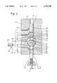
- FIG. 1is a schematic sectional view of a preferred embodiment of a hydraulically working, freely activatable valve control device in a housing of an internal-combustion engine, in a representation with the valve closed;
- FIG. 2shows the valve control device according to FIG. 1 in a representation with the valve partially opened
- FIG. 3shows the valve control device according to FIGS. 1 and 2 in a representation with the valve opened completely.
- FIGS. 1 to 3show a hydraulic, freely activatable valve control device having a stroke valve 1, together with a valve stem 2, which is guided in valve guides 3 and 4 in a housing 5 of an internal-combustion engine not shown in more detail.
- the stroke valve 1comprises a valve disc 6, together with a valve seat 7, and a control piston 8 which is described in more detail below and which is fastened to the valve stem 2.
- the control piston 8comprises two plunger pistons 9 and 10, the plunger piston 9 being fastened to the top side of the control piston 8 and the plunger piston 10 to the underside of control piston 8.
- a cavityArranged in the housing 5, between the two valve guides 3 and 4, is a cavity which forms a working space 11 for the control piston 8 together with the plunger pistons 9 and 10.
- the valve stem 2passes through the working space 11, there being arranged between a spring receptacle 12 of the valve stem 2 and a spring receptacle 13 of the housing 5 a first spring 14 acting in the valve-closing direction.
- the spring 14is a helical compression spring 15 which is supported in the spring receptacles 12, 13 and which is fixed to these receptacles.
- a second spring 16Arranged on the side of the valve stem 2 facing away from the valve disc 6 is a second spring 16 which acts in the valve-opening direction and which consists of an oil-pressure spring 17.
- This oil pressure spring 17comprises a stroke space 18 which is connected to a control groove 21 of the valve stem 2 by means of pressure ducts 19 and 20 extending in the valve stem 2, the control groove 21 possessing two control edges 22 and 23.
- the control groove 21is periodically connected hydraulically in a way described in more detail below to a pressure duct 24 in the form of an annular groove, in the housing 5, the pressure duct being arranged around the valve stem 2 and being connected to a pressure supply conduit 45-45' via a duct 25 together with a conduit 26.
- the working space 11encloses the control piston 8 together with the plunger pistons 9 and 10, two pressure spaces 28 and 29 assigned in each case to a plunger piston 9 and 10 arranged in the working space 11.
- the plunger piston 9can be plunged into the pressure space 28 in the region of the upper end position of the control piston 8 and the plunger piston 10 can be plunged into the pressure space 29 in the region of the lower end position of the control piston 8, with the result that the plunger piston 9 or 10 forms a partial limitation of the respectively associated pressure space 28 or 29.
- working fluidfor example, lubricating oil or fuel
- working fluid pumpworking fluid pump
- switching valve 27a switching valve 27 and supply conduit 30.
- the pressure space 28can be relieved of pressure into an annular pressure relief duct 34 via a connecting duct 31 (see FIG. 1)
- the pressure space 29can be relieved of pressure into an annular pressure-relief duct 35 via a connecting duct 32 (see FIG. 3).
- the control piston 8is designed in such a way that, after one of the two plunger pistons 9, 10 has emerged from the associated pressure space 28 and 29, the working space 11 and the two pressure spaces 28 and 29 are hydraulically connected to one another, the hydraulic connection of the two pressure spaces 28, 29 being formed by the working space 11 itself.
- the prestressing force of the second spring 16(oil-pressure spring 17) can be regulated in a way described in more detail below while the hydraulic valve control device is in operation.
- the first spring 14(helical compression spring 15) holds the stroke valve 1 in a closed position (see FIG. 1).
- the energy loss occurring during a movement cyclecan be compensated by a cyclic variation in the prestressing force of the second spring 16 (oil pressure spring 17).
- the working pressure of the oil-pressure spring 17can be built up from the pressure supply conduit 45-45' via the pressure ducts 19, 20 and the control groove 21 via the pressure duct 24 in the form of an annular groove together with the conduit 26 (see FIG. 1).
- the switching valve 27is connected on the one hand, via the supply conduit 30 to the working space 11 and, on the other hand, via the pressure supply conduit 45-45' to the working-medium pump and to the reservoir 38 of working fluid.
- Hydraulically active surfaces F1-F6 of the control piston 8are oriented perpendicularly or obliquely to a stroke-valve axis 33.
- a force component parallel to the stroke-valve axis 33the force component corresponding to the projecting surface fraction of the respective surface F1-F6, is generated.
- the hydraulically active surfaces F1-F6 of the control piston 8 together with the plunger pistons 9, 10are of equal size in the valve-opening direction and in the valve-closing direction in a position lifted off from the end positions of the control piston 8.
- the surfaces F1/F6, F2/F5 and F3/F4are of equal size and are arranged symmetrically with respect to a plane perpendicular to the stroke-valve axis 33.
- the open stroke valve 1(see FIG. 3) can be held in its opened position as a result of the pressure loading of the working fluid in the working space 11 counter to the pressure of the first spring 14 (helical compression spring 15) and a pressure possibly still prevailing in the pressure space 29 and counter to a force on the valve disc 6 possibly acting in the valve-closing direction.
- the annular pressure-relief ducts 34 and 35are located respectively above and below the working space 11 and are each connected via a connecting conduit 36 and 37 to a reservoir of the working fluid 38.
- the hydraulic connection between the connecting duct 31 and pressure relief duct 34is controlled by a control groove 39 arranged in the valve stem 2, together with a control edge 40.
- the hydraulic connection between the connecting duct 32 and the annular pressure-relief duct 35is made by a control groove 42 arranged in the valve stem 2, together with a control edge 44.
- the connecting ducts 31, 32open into the respective control groove 39 and 42 at points 41, 43.
- the oblique surface F3is pressed against a seat S1 of the working space 11, with the result that the pressure space 28 is separated hydraulically from the working space 11 (see FIG. 1).
- the oblique surface F4is pressed against a seat S2 of the working space 11, with the result that the pressure space 29 is separated hydraulically from the working space 11 (see FIG. 3).
- the oil-pressure spring 17 and the control piston 8form, together with the helical compression spring 15 and the stroke valve 1, a spring/mass system.
- the stroke valve 1In the absence of a supply pressure of the working fluid, the stroke valve 1 is always closed, since the valve disc 6 is pressed into the valve seat 7 by the prestressing force of the helical compression spring 15.
- a supply pressureis built up and bears on the switching valve 27 via the pressure supply conduit 45. Irrespective of the switching position of the switching valve, the pressure loading of the conduit 26 with working fluid is guaranteed via the pressure supply conduit 45'.
- the pressureis built up in the oil-pressure spring 17 via the conduit 26, the duct 25, the control groove 21 and the pressure ducts 20 and 19.
- the oil pressure spring 17is thus tensioned.
- the pressure in the working space 11is likewise built up.
- the spring/mass systemnevertheless remains in its upper end position (see FIG. 1), since the top side of the control piston 8 (plunger piston 9) is relieved by means of the connection of the pressure space 28 to the reservoir 38 of working fluid via the connecting duct 31 together with the annular pressure-relief duct 34 and connecting conduit 36.
- the pressure in the working space 11loads the corresponding hydraulic active surface on the control piston 8 (annular surfaces F5 and F6 perpendicular to the stroke-valve axis 33 and the annular surface F4 oblique relative to the latter) and brings about a resultant counterforce which presses the control piston 8 upwards.
- the stroke valve 1therefore remains closed.
- the switching valve 27is activated, the working space 11 is separated from the pressure supply and is connected to the reservoir 38.
- the hydraulic active surface on the control piston 8is thereby also relieved of pressure and the counterforce thus reduced.
- the control piston 8 together with the stroke valve 1can then commence its oscillation from the upper end position into the lower.
- valve stem 2When the plunger piston 9 emerges from the pressure space 28, the valve stem 2, by means of its control edge 40, closes the hydraulic connection of the pressure space 28 to the annular pressure-relief duct 34. The switching valve 27 is then switched over and the working pressure 11 is put under pressure again. This action has no influence on the movement of the control piston 8. It must be guaranteed, however, that the pressure build-up in the working space 11 has been completed before the lower end position of the control piston 8 is reached, since the pressure in the working space 11 is then required in order to retain the spring/mass system in its lower end position.
- the valve stem 2Shortly before the lower end position of the control piston 8 is reached, the valve stem 2, by means of its control edge 44, opens the hydraulic connection between the connecting duct 32 and annular pressure relief duct 35.
- the plunger piston 10closes the connection between the working space 11 and pressure space 29, the different pressures on the hydraulic active surfaces of the control piston 8 (plunger pistons 9/10) bringing about a resultant force on the control piston 8 in the valve-opening direction, the said force pushing the spring/mass system into its lower end position and retaining it there, with the result that the stroke valve 1 (see FIG. 3) remains opened.
- the energy loss occurring during the movement cycleis compensated by a cyclic variation in the prestressing force of the oil-pressure spring. This takes place, in the lower end position of the spring/mass system, by the reduction of a still prevailing residual pressure in the oil-pressure spring 17 into the annular pressure-relief duct 34 via the pressure ducts 19 and 20 together with the control groove 21 (see FIG. 3).
- the control edge 23 of the control groove 21is located in the region of the annular pressure-relief duct 34.
- the helical compression spring 15thus prestressed to a greater extent than the oil-pressure spring 17 ensures that the upper end position is reached.
- the lattercan no longer be compressed to the original initial pressure.
- the resulting pressure differenceis therefore compensated, in the upper end position of the spring/mass system (see FIG. 1), via the conduit 26 together with the duct 25, the control groove 21 and the pressure ducts 19, 20, 24 of the oil-pressure spring 17. This ensures that, at the commencement of the next work cycle, the oil-pressure spring 17 is prestressed to a greater extent than the helical compression spring 15.
- the energy supplied to the spring/mass systemcan be varied in the two end positions of the system independently of one another by variation in the pressures between which the oil-pressure spring 17 is operated.
- These pressure variationscan be implemented by pressure-regulating arrangements (not shown) for the pressures prevailing in the pressure supply conduit 45 and in the reservoir 38.
- valve strokesalong with control times of, for example, 5-10 milliseconds, with an energy consumption of approximately 100-250 watts (in the case of 50 valve openings per second), can be brought about without difficulty.
- control of the conduit 26can also take place via a further switching valve.
- valve stem 2 together with the control piston 8is made in one part, but the valve stem and control piston can, of course, also consist of two or more parts which either are fastened to one another by fastening means or are connected to one another by non-positive connection (for example, by being held together by pressure forces exerted by spring means) or by coupling means (for example, mechanical transmission).
- the periodic separation of the pressure spaces 28, 29 from the working space 11can take place by means of conical or flat sealing seats which are formed between the pressure spaces 28 and 29 and the control piston 8.
- the surfaces S1/F3 and S2/F4could also be designed, instead of as a conical seat (as shown in the exemplary embodiment), also as a flat sealing seat.
- the periodic separation of the pressure spaces 28, 29can take place solely by means of these conical or flat sealing seats, with the result that the plunger piston according to the above exemplary embodiment is then omitted.
- the above-described, freely activatable valve control devicecan be used for all controls of stroke valves, in particular for inlet and outlet valves of internal-combustion engines and piston compressors.
Landscapes
- Engineering & Computer Science (AREA)
- Mechanical Engineering (AREA)
- General Engineering & Computer Science (AREA)
- Valve Device For Special Equipments (AREA)
- Lifting Devices For Agricultural Implements (AREA)
Abstract
Description
Claims (20)
Applications Claiming Priority (2)
| Application Number | Priority Date | Filing Date | Title |
|---|---|---|---|
| DE19501495.2 | 1995-01-19 | ||
| DE19501495ADE19501495C1 (en) | 1995-01-19 | 1995-01-19 | Hydraulic valve control device for I.C. engine |
Publications (1)
| Publication Number | Publication Date |
|---|---|
| US5595148Atrue US5595148A (en) | 1997-01-21 |
Family
ID=7751840
Family Applications (1)
| Application Number | Title | Priority Date | Filing Date |
|---|---|---|---|
| US08/588,768Expired - LifetimeUS5595148A (en) | 1995-01-19 | 1996-01-19 | Hydraulic valve control device |
Country Status (5)
| Country | Link |
|---|---|
| US (1) | US5595148A (en) |
| DE (1) | DE19501495C1 (en) |
| FR (1) | FR2729731B1 (en) |
| GB (1) | GB2297124B (en) |
| IT (1) | IT1283875B1 (en) |
Cited By (31)
| Publication number | Priority date | Publication date | Assignee | Title |
|---|---|---|---|---|
| US5682846A (en)* | 1996-12-19 | 1997-11-04 | Eaton Corporation | Engine valve actuator with differential area pistons |
| US5765515A (en)* | 1996-05-31 | 1998-06-16 | Daimler-Benz Ag | Controllable hydraulic valve operating mechanism |
| US5809950A (en)* | 1996-05-31 | 1998-09-22 | Daimler-Benz Ag | Hydraulic valve control arrangement |
| US5829396A (en)* | 1996-07-16 | 1998-11-03 | Sturman Industries | Hydraulically controlled intake/exhaust valve |
| US6044815A (en)* | 1998-09-09 | 2000-04-04 | Navistar International Transportation Corp. | Hydraulically-assisted engine valve actuator |
| US6067946A (en)* | 1996-12-16 | 2000-05-30 | Cummins Engine Company, Inc. | Dual-pressure hydraulic valve-actuation system |
| US6082243A (en)* | 1997-03-15 | 2000-07-04 | Fev Motorentechnik Gmbh & Co. Kg | Fluid controlled switching unit |
| US6148778A (en) | 1995-05-17 | 2000-11-21 | Sturman Industries, Inc. | Air-fuel module adapted for an internal combustion engine |
| US6167853B1 (en)* | 1997-04-17 | 2001-01-02 | Daimlerchrysler Ag | Hydraulic control device for at least one lifting valve |
| US6263842B1 (en) | 1998-09-09 | 2001-07-24 | International Truck And Engine Corporation | Hydraulically-assisted engine valve actuator |
| US6349686B1 (en) | 2000-08-31 | 2002-02-26 | Caterpillar Inc. | Hydraulically-driven valve and hydraulic system using same |
| US20030015155A1 (en)* | 2000-12-04 | 2003-01-23 | Turner Christopher Wayne | Hydraulic valve actuation systems and methods |
| US6601552B2 (en)* | 1998-11-19 | 2003-08-05 | Daimlerchrysler Ag | Hydraulically controllable globe valve |
| US20040020453A1 (en)* | 2002-02-05 | 2004-02-05 | Yager James H. | Damped valve controller |
| US20040065855A1 (en)* | 2002-10-07 | 2004-04-08 | Van Weelden Curtis L. | Hydraulic actuator for operating an engine cylinder valve |
| US6786186B2 (en) | 1998-09-09 | 2004-09-07 | International Engine Intellectual Property Company, Llc | Unit trigger actuator |
| WO2004085858A1 (en)* | 2003-03-24 | 2004-10-07 | Yokohama Tlo Company,Ltd. | Variable valve system of internal combustion engine and control method thereof, and hydraulic actuator |
| US20040194744A1 (en)* | 2003-04-01 | 2004-10-07 | Yager James H. | Hydraulic actuator cartridge for a valve |
| US20040210377A1 (en)* | 2002-02-01 | 2004-10-21 | Ford Global Technologies, Inc. | Method and system for inferring torque output of a variable compression ratio engine |
| US20060254542A1 (en)* | 2005-05-10 | 2006-11-16 | Strickler Scott L | Hydraulic valve actuation system with valve lash adjustment |
| US20060283411A1 (en)* | 2005-06-16 | 2006-12-21 | Zheng Lou | Variable valve actuator |
| US20060283408A1 (en)* | 2005-06-16 | 2006-12-21 | Zheng Lou | Variable valve actuator |
| US20070022988A1 (en)* | 2005-08-01 | 2007-02-01 | Zheng Lou | Variable valve actuator |
| US20070022986A1 (en)* | 2005-08-01 | 2007-02-01 | Zheng Lou | Variable valve actuator |
| US20070272180A1 (en)* | 2006-05-26 | 2007-11-29 | Zheng Lou | Variable valve actuator with latch at one end |
| US20080054205A1 (en)* | 2006-08-30 | 2008-03-06 | Zheng Lou | Variable valve actuator with latches at both ends |
| CN104314635A (en)* | 2014-09-04 | 2015-01-28 | Lgd技术有限责任公司 | Variable driver |
| US8978604B2 (en) | 2012-03-31 | 2015-03-17 | Jiangsu Gongda Power Technologies Co., Ltd. | Variable valve actuator |
| US9347466B2 (en) | 2011-10-21 | 2016-05-24 | Freevalve Ab | Actuator |
| US9926178B2 (en) | 2014-08-20 | 2018-03-27 | Crown Equipment Corporation | Actuator in a lift truck |
| US20210154818A1 (en)* | 2018-01-19 | 2021-05-27 | Max Co., Ltd. | Driving tool |
Families Citing this family (2)
| Publication number | Priority date | Publication date | Assignee | Title |
|---|---|---|---|---|
| DE19905364C1 (en)* | 1999-02-10 | 2000-08-03 | Daimler Chrysler Ag | Method for operating an internal combustion engine with variable gas exchange control times |
| DE102005056012A1 (en)* | 2005-11-24 | 2007-06-06 | Volkswagen Ag | Hydraulic valve control device for lifting valve e.g. gas shuttle valve of internal-combustion engine of motor vehicle, has main piston towards closing position of stroke valve |
Citations (5)
| Publication number | Priority date | Publication date | Assignee | Title |
|---|---|---|---|---|
| DE3836725C1 (en)* | 1988-10-28 | 1989-12-21 | Daimler-Benz Aktiengesellschaft, 7000 Stuttgart, De | |
| US5193495A (en)* | 1991-07-16 | 1993-03-16 | Southwest Research Institute | Internal combustion engine valve control device |
| US5287829A (en)* | 1989-08-28 | 1994-02-22 | Rose Nigel E | Fluid actuators |
| US5529030A (en)* | 1992-02-26 | 1996-06-25 | Rose; Nigel E. | Fluid actuators |
| US5531192A (en)* | 1994-08-04 | 1996-07-02 | Caterpillar Inc. | Hydraulically actuated valve system |
Family Cites Families (1)
| Publication number | Priority date | Publication date | Assignee | Title |
|---|---|---|---|---|
| US5224683A (en)* | 1992-03-10 | 1993-07-06 | North American Philips Corporation | Hydraulic actuator with hydraulic springs |
- 1995
- 1995-01-19DEDE19501495Apatent/DE19501495C1/ennot_activeExpired - Fee Related
- 1996
- 1996-01-03GBGB9600065Apatent/GB2297124B/ennot_activeExpired - Fee Related
- 1996-01-12ITIT96RM000016Apatent/IT1283875B1/enactiveIP Right Grant
- 1996-01-18FRFR9600531Apatent/FR2729731B1/ennot_activeExpired - Fee Related
- 1996-01-19USUS08/588,768patent/US5595148A/ennot_activeExpired - Lifetime
Patent Citations (5)
| Publication number | Priority date | Publication date | Assignee | Title |
|---|---|---|---|---|
| DE3836725C1 (en)* | 1988-10-28 | 1989-12-21 | Daimler-Benz Aktiengesellschaft, 7000 Stuttgart, De | |
| US5287829A (en)* | 1989-08-28 | 1994-02-22 | Rose Nigel E | Fluid actuators |
| US5193495A (en)* | 1991-07-16 | 1993-03-16 | Southwest Research Institute | Internal combustion engine valve control device |
| US5529030A (en)* | 1992-02-26 | 1996-06-25 | Rose; Nigel E. | Fluid actuators |
| US5531192A (en)* | 1994-08-04 | 1996-07-02 | Caterpillar Inc. | Hydraulically actuated valve system |
Cited By (56)
| Publication number | Priority date | Publication date | Assignee | Title |
|---|---|---|---|---|
| US6148778A (en) | 1995-05-17 | 2000-11-21 | Sturman Industries, Inc. | Air-fuel module adapted for an internal combustion engine |
| US6173685B1 (en)* | 1995-05-17 | 2001-01-16 | Oded E. Sturman | Air-fuel module adapted for an internal combustion engine |
| US5765515A (en)* | 1996-05-31 | 1998-06-16 | Daimler-Benz Ag | Controllable hydraulic valve operating mechanism |
| US5809950A (en)* | 1996-05-31 | 1998-09-22 | Daimler-Benz Ag | Hydraulic valve control arrangement |
| US5829396A (en)* | 1996-07-16 | 1998-11-03 | Sturman Industries | Hydraulically controlled intake/exhaust valve |
| US6067946A (en)* | 1996-12-16 | 2000-05-30 | Cummins Engine Company, Inc. | Dual-pressure hydraulic valve-actuation system |
| US5682846A (en)* | 1996-12-19 | 1997-11-04 | Eaton Corporation | Engine valve actuator with differential area pistons |
| US6082243A (en)* | 1997-03-15 | 2000-07-04 | Fev Motorentechnik Gmbh & Co. Kg | Fluid controlled switching unit |
| US6167853B1 (en)* | 1997-04-17 | 2001-01-02 | Daimlerchrysler Ag | Hydraulic control device for at least one lifting valve |
| US6044815A (en)* | 1998-09-09 | 2000-04-04 | Navistar International Transportation Corp. | Hydraulically-assisted engine valve actuator |
| US6263842B1 (en) | 1998-09-09 | 2001-07-24 | International Truck And Engine Corporation | Hydraulically-assisted engine valve actuator |
| US6338320B1 (en) | 1998-09-09 | 2002-01-15 | International Truck & Engine Corporation | Hydraulically-assisted engine valve actuator |
| US6786186B2 (en) | 1998-09-09 | 2004-09-07 | International Engine Intellectual Property Company, Llc | Unit trigger actuator |
| US6601552B2 (en)* | 1998-11-19 | 2003-08-05 | Daimlerchrysler Ag | Hydraulically controllable globe valve |
| US6349686B1 (en) | 2000-08-31 | 2002-02-26 | Caterpillar Inc. | Hydraulically-driven valve and hydraulic system using same |
| US6739293B2 (en) | 2000-12-04 | 2004-05-25 | Sturman Industries, Inc. | Hydraulic valve actuation systems and methods |
| US20030015155A1 (en)* | 2000-12-04 | 2003-01-23 | Turner Christopher Wayne | Hydraulic valve actuation systems and methods |
| US20040210377A1 (en)* | 2002-02-01 | 2004-10-21 | Ford Global Technologies, Inc. | Method and system for inferring torque output of a variable compression ratio engine |
| US20040020453A1 (en)* | 2002-02-05 | 2004-02-05 | Yager James H. | Damped valve controller |
| US20040065855A1 (en)* | 2002-10-07 | 2004-04-08 | Van Weelden Curtis L. | Hydraulic actuator for operating an engine cylinder valve |
| US6782852B2 (en) | 2002-10-07 | 2004-08-31 | Husco International, Inc. | Hydraulic actuator for operating an engine cylinder valve |
| WO2004085858A1 (en)* | 2003-03-24 | 2004-10-07 | Yokohama Tlo Company,Ltd. | Variable valve system of internal combustion engine and control method thereof, and hydraulic actuator |
| JPWO2004085858A1 (en)* | 2003-03-24 | 2006-06-29 | よこはまティーエルオー株式会社 | Variable valve operating apparatus for internal combustion engine, control method therefor, and hydraulic actuator |
| US7178489B2 (en) | 2003-03-24 | 2007-02-20 | Yokohama Tlo Company, Ltd. | Variable valve system of internal combustion engine and hydraulic actuator |
| US20040194744A1 (en)* | 2003-04-01 | 2004-10-07 | Yager James H. | Hydraulic actuator cartridge for a valve |
| US6978747B2 (en) | 2003-04-01 | 2005-12-27 | International Engine Intellectual Property Company, Llc | Hydraulic actuator cartridge for a valve |
| US20060254542A1 (en)* | 2005-05-10 | 2006-11-16 | Strickler Scott L | Hydraulic valve actuation system with valve lash adjustment |
| US7347172B2 (en) | 2005-05-10 | 2008-03-25 | International Engine Intellectual Property Company, Llc | Hydraulic valve actuation system with valve lash adjustment |
| US20060283410A1 (en)* | 2005-06-16 | 2006-12-21 | Zheng Lou | Variable valve actuator |
| US7156058B1 (en) | 2005-06-16 | 2007-01-02 | Zheng Lou | Variable valve actuator |
| CN101198772B (en)* | 2005-06-16 | 2010-05-19 | 江苏公大动力技术有限公司 | Variable valve actuator |
| US20060283411A1 (en)* | 2005-06-16 | 2006-12-21 | Zheng Lou | Variable valve actuator |
| US7302920B2 (en) | 2005-06-16 | 2007-12-04 | Zheng Lou | Variable valve actuator |
| US20060283408A1 (en)* | 2005-06-16 | 2006-12-21 | Zheng Lou | Variable valve actuator |
| US7194991B2 (en) | 2005-06-16 | 2007-03-27 | Zheng Lou | Variable valve actuator |
| WO2007016519A3 (en)* | 2005-08-01 | 2007-05-03 | Lgd Technologies Llc | Variable valve actuator |
| US7213549B2 (en) | 2005-08-01 | 2007-05-08 | Zheng Lou | Variable valve actuator |
| US7290509B2 (en) | 2005-08-01 | 2007-11-06 | Zheng Lou | Variable valve actuator |
| US20070022987A1 (en)* | 2005-08-01 | 2007-02-01 | Zheng Lou | Variable valve actuator |
| US20070022986A1 (en)* | 2005-08-01 | 2007-02-01 | Zheng Lou | Variable valve actuator |
| US7370615B2 (en) | 2005-08-01 | 2008-05-13 | Lgd Technology, Llc | Variable valve actuator |
| US20070022988A1 (en)* | 2005-08-01 | 2007-02-01 | Zheng Lou | Variable valve actuator |
| US20070272180A1 (en)* | 2006-05-26 | 2007-11-29 | Zheng Lou | Variable valve actuator with latch at one end |
| CN101460712B (en)* | 2006-05-26 | 2012-01-18 | Lgd技术有限责任公司 | Variable valve actuator with latch at one end |
| WO2007139838A3 (en)* | 2006-05-26 | 2008-07-17 | Lgd Technology Llc | Variable valve actuator with latch at one end |
| US7421987B2 (en)* | 2006-05-26 | 2008-09-09 | Lgd Technology, Llc | Variable valve actuator with latch at one end |
| US7766302B2 (en)* | 2006-08-30 | 2010-08-03 | Lgd Technology, Llc | Variable valve actuator with latches at both ends |
| US20080054205A1 (en)* | 2006-08-30 | 2008-03-06 | Zheng Lou | Variable valve actuator with latches at both ends |
| CN101135401B (en)* | 2006-08-30 | 2012-04-18 | Lgd技术有限责任公司 | Variable valve actuator with latches at both ends |
| US9347466B2 (en) | 2011-10-21 | 2016-05-24 | Freevalve Ab | Actuator |
| US8978604B2 (en) | 2012-03-31 | 2015-03-17 | Jiangsu Gongda Power Technologies Co., Ltd. | Variable valve actuator |
| US9926178B2 (en) | 2014-08-20 | 2018-03-27 | Crown Equipment Corporation | Actuator in a lift truck |
| CN104314635A (en)* | 2014-09-04 | 2015-01-28 | Lgd技术有限责任公司 | Variable driver |
| CN104314635B (en)* | 2014-09-04 | 2017-01-11 | 宁波华液机器制造有限公司 | Variable driver |
| US20210154818A1 (en)* | 2018-01-19 | 2021-05-27 | Max Co., Ltd. | Driving tool |
| US11911885B2 (en)* | 2018-01-19 | 2024-02-27 | Max Co., Ltd. | Driving tool |
Also Published As
| Publication number | Publication date |
|---|---|
| ITRM960016A0 (en) | 1996-01-12 |
| GB9600065D0 (en) | 1996-03-06 |
| IT1283875B1 (en) | 1998-05-07 |
| GB2297124A (en) | 1996-07-24 |
| DE19501495C1 (en) | 1995-11-23 |
| GB2297124B (en) | 1997-01-08 |
| FR2729731A1 (en) | 1996-07-26 |
| FR2729731B1 (en) | 1998-06-19 |
| ITRM960016A1 (en) | 1997-07-12 |
Similar Documents
| Publication | Publication Date | Title |
|---|---|---|
| US5595148A (en) | Hydraulic valve control device | |
| US5809950A (en) | Hydraulic valve control arrangement | |
| US5609134A (en) | Operating mechanism for an engine brake valve of an internal combustion engine | |
| US5765515A (en) | Controllable hydraulic valve operating mechanism | |
| EP0790402B1 (en) | Fuel injector for internal combustion engines | |
| US6871618B2 (en) | Valve actuating device, and method for controlling same | |
| GB2301626A (en) | Fuel injector control | |
| KR20080100191A (en) | Method and apparatus for operating a valve in a combustion chamber of a combustion engine, and combustion engine | |
| US4941438A (en) | Hydraulic valve-lash adjuster | |
| US5273013A (en) | Device for controlling an outlet valve in the engine brake mode | |
| US5735242A (en) | Fuel pressure activated engine compression braking system | |
| JPH11166653A (en) | Valve for controlling liquid | |
| KR20030017633A (en) | Fuel injection device with pressure translation device and pressure translation device | |
| KR920701616A (en) | Hydraulic Valve Controls for Internal Combustion Engines | |
| US6848400B2 (en) | Gas exchange valve mechanism for an internal combustion engine | |
| KR20020069263A (en) | Fuel-injection system for internal combustion engines | |
| EP1227241B1 (en) | Fuel injector assembly and internal combustion engine including same | |
| JP2003515045A (en) | Fuel injection valve for internal combustion engine | |
| JP2004521248A (en) | Fuel injection device used for internal combustion engine | |
| US20040089829A1 (en) | Device for controlling a gas exchange valve | |
| CN1276038A (en) | Device for actuating gas exchange valves of piston-type internal combustion engines | |
| JP2003513195A (en) | Fuel injection valve used for internal combustion engine | |
| JP2005513332A (en) | Fuel injection device for an internal combustion engine | |
| JPH094425A (en) | Variable valve train for internal combustion engines | |
| JPS6062616A (en) | Valve operation/non-operation switching equipment for engine |
Legal Events
| Date | Code | Title | Description |
|---|---|---|---|
| AS | Assignment | Owner name:MERCEDES-BENZ AG, GERMANY Free format text:ASSIGNMENT OF ASSIGNORS INTEREST;ASSIGNORS:LETSCHE, ULRICH;IBERLE, FRANK;REHBERGER, ANDREAS;REEL/FRAME:007928/0512 Effective date:19960120 | |
| STCF | Information on status: patent grant | Free format text:PATENTED CASE | |
| FEPP | Fee payment procedure | Free format text:PAYOR NUMBER ASSIGNED (ORIGINAL EVENT CODE: ASPN); ENTITY STATUS OF PATENT OWNER: LARGE ENTITY | |
| AS | Assignment | Owner name:DAIMLER-BENZ AKTIENGESELLSCHAFT, GERMANY Free format text:MERGER RE-RECORD TO CORRECT THE NUMBER OF MICROFILM PAGES FROM 60 TO 98 AT REEL 9360, FRAME 0937.;ASSIGNOR:MERCEDES-BENZ AG;REEL/FRAME:009827/0145 Effective date:19970605 Owner name:DAIMLER-BENZ AKTIENGESELLSCHAFT, GERMANY Free format text:MERGER;ASSIGNOR:MERCEDES-BENZ AG;REEL/FRAME:009360/0937 Effective date:19970605 | |
| AS | Assignment | Owner name:DAIMLERCHRYSLER AG, GERMANY Free format text:MERGER;ASSIGNOR:DAIMLER-BENZ AKTIENGESELLSCHAFT;REEL/FRAME:010133/0556 Effective date:19990108 | |
| FEPP | Fee payment procedure | Free format text:PAYER NUMBER DE-ASSIGNED (ORIGINAL EVENT CODE: RMPN); ENTITY STATUS OF PATENT OWNER: LARGE ENTITY Free format text:PAYOR NUMBER ASSIGNED (ORIGINAL EVENT CODE: ASPN); ENTITY STATUS OF PATENT OWNER: LARGE ENTITY | |
| FPAY | Fee payment | Year of fee payment:4 | |
| FPAY | Fee payment | Year of fee payment:8 | |
| AS | Assignment | Owner name:DAIMLER AG, GERMANY Free format text:CHANGE OF NAME;ASSIGNOR:DAIMLERCHRYSLER AG;REEL/FRAME:020976/0889 Effective date:20071019 Owner name:DAIMLER AG,GERMANY Free format text:CHANGE OF NAME;ASSIGNOR:DAIMLERCHRYSLER AG;REEL/FRAME:020976/0889 Effective date:20071019 | |
| FPAY | Fee payment | Year of fee payment:12 | |
| AS | Assignment | Owner name:DAIMLER AG, GERMANY Free format text:CORRECTIVE ASSIGNMENT TO CORRECT THE APPLICATION NO. 10/567,810 PREVIOUSLY RECORDED ON REEL 020976 FRAME 0889. ASSIGNOR(S) HEREBY CONFIRMS THE CHANGE OF NAME;ASSIGNOR:DAIMLERCHRYSLER AG;REEL/FRAME:053583/0493 Effective date:20071019 |