US5594963A - Pressure relief air mattress and related system - Google Patents
Pressure relief air mattress and related systemDownload PDFInfo
- Publication number
- US5594963A US5594963AUS08/608,996US60899696AUS5594963AUS 5594963 AUS5594963 AUS 5594963AUS 60899696 AUS60899696 AUS 60899696AUS 5594963 AUS5594963 AUS 5594963A
- Authority
- US
- United States
- Prior art keywords
- air
- mattress
- cushions
- cushion
- patient
- Prior art date
- Legal status (The legal status is an assumption and is not a legal conclusion. Google has not performed a legal analysis and makes no representation as to the accuracy of the status listed.)
- Expired - Lifetime
Links
Images


Classifications
- A—HUMAN NECESSITIES
- A61—MEDICAL OR VETERINARY SCIENCE; HYGIENE
- A61G—TRANSPORT, PERSONAL CONVEYANCES, OR ACCOMMODATION SPECIALLY ADAPTED FOR PATIENTS OR DISABLED PERSONS; OPERATING TABLES OR CHAIRS; CHAIRS FOR DENTISTRY; FUNERAL DEVICES
- A61G7/00—Beds specially adapted for nursing; Devices for lifting patients or disabled persons
- A61G7/05—Parts, details or accessories of beds
- A61G7/057—Arrangements for preventing bed-sores or for supporting patients with burns, e.g. mattresses specially adapted therefor
- A61G7/05769—Arrangements for preventing bed-sores or for supporting patients with burns, e.g. mattresses specially adapted therefor with inflatable chambers
Definitions
- the present inventionrelates to therapeutic beds and mattress systems designed to prevent, reduce and treat complications of immobility. More particularly, the present invention relates to air (or air-and-foam composite) mattresses which provide therapeutic benefits in part by reducing patient interface pressures, thereby enabling better circulation in the patient, in conjunction with related systems that combine to provide a bed ideal for easy use in home settings and the like.
- Examples of commercially available mattresses that address some of the prior art concernsare as the "First Step” family of mattress systems manufactured by the present Applicant, Kinetic Concepts, Inc. of San Antonio, Tex.
- One member of that family, the "First Step M.R.S.”is a mattress replacement system that includes a three-sectioned air mattress supported on a thin foam sub-mattress, with a lightweight blower designed to hook to the footboard of an existing bed frame. None of the "First Step” products are made integral with a frame, although many other available air and foam mattresses are.
- the present inventionrepresents an improved and novel system over the prior art. It is characterized by a number of advantages which increase its utility over the prior art devices, including the innovative integration of a novel mattress structure with a lightweight, versatile frame and an efficient air supply system. Such a system is ideal for patients who would benefit from a pressure relieving surface assisting in the prevention and counteraction of skin breakdown as well as from enhanced circulation, or to assist in pain management.
- a primary object of the present inventionis to provide an improved therapeutic support system for a variety of patients, including many who are immobile for varied lengths of time. Providing such a system with a lightweight, versatile structure that can be easily disassembled and moved through narrow halls, doors, up stairs and the like is also an important object. Another object is to provide a therapeutic, pressure-relieving mattress that includes separable air cushions for ease in handling, cleaning and service. Simplicity, ease of use, durability, and cost efficient therapy are still other objects. A related object is to provide such a mattress which does not compromise the safety or therapeutic benefits for critically ill patients.
- the present inventionaddresses such objects by providing a mattress system which includes the elements and serves the purposes described hereafter and as set forth in the claims appended hereto.
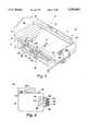
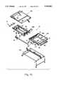
- FIG. 1shows an isometric perspective of bed 10.
- FIG. 2Ashows an isometric perspective of the foam core 35 of sub-mattress 34.
- FIG. 2Bshows an isometric perspective of the cover 40 of sub-mattress 34.
- FIGS. 3A-3Dillustrate the parts and manufacturing process for sub-mattress 50.
- FIG. 4shows an isometric perspective of cushion 33.
- FIGS. 5A-5Care plan views showing various stages in fabrication of cushion 33.
- FIG. 5Dshows an exploded, isometric perspective of nipple 138 and the manner of connection with cushion 33.
- FIG. 6shows an elevation view of cover sheet 11.
- FIGS. 7A-Cshow exploded perspective of air supply unit 100.
- FIG. 8shows a frontal view of the air supply unit 100.
- FIGS. 9 and 10show a circuitry schematic for controller 177.
- FIGS. 11A & 11Bshow a circuitry schematic for hand control 200.
- FIGS. 12A-Cshow the pendant hand control 200.
- FIGS. 13-15show frame assembly 20 in a form easily understood.
- Air bed 10is a patient support of the type commonly referred to as a low-air-loss bed and is designed to provide pressure relief for a patient supported thereon.
- Pressure reliefis a common reference in this field meaning that the interface pressure between the patient and the bed's patient supporting surfaces (namely cover sheet 11 of bed 10) are generally maintained below capillary closure pressures (generally considered to be 32 millimeters mercury) at all points on the patient's body when the patient is lying in the supine position.
- capillary closure pressuresgenerally considered to be 32 millimeters mercury
- Such a bed 10is primarily indicated for pressure ulcers, skin flaps and grafts, draining wounds, advanced arthritis, oncology, chronic musculoskeletal disorders, chronic neurological disorders, and pain management, although it is not recommended for patients requiring cervical traction or patients with spinal cord injuries. Evenly distributed pressures also tend to make for a more comfortable resting surface.
- bed 10is also easily disassembled to allow set-up in rooms upstairs and beyond narrow hallways and doorways; is lightweight to allow set-up in rooms that cannot structurally support heavy air-fluidized or conventional low-air-loss specialty beds; is simplified in operation for the care giver and patient in the home environment and is cost efficient in use.
- bed 10(or a bed substantially like bed 10 in most respects) will be commercially available from Applicant Kinetic Concepts, Inc. or its subsidiary Kinetic Concepts Therapeutic Services, Inc., both based in San Antonio, Tex., under the trademark "HomeKair Bed”.
- Other equivalent bedsmay also soon be commercially available through said Applicant.
- the features of bed 10 and how to make and use itwill be readily understood by those of ordinary skill in the art from an inspection of the said HomeKair Bed made in light of this description and the accompanying drawings.
- bed 10basically comprises frame assembly 20, mattress assembly 50, and air supply unit 100, together with various other components linking those three main assemblies.
- Each of these assemblies 20, 50 and 100will be described in more detail below.
- the overall interplay of the assemblies 20, 50 and 100may be best understood with reference to FIG. 1, wherein it is shown that frame assembly 20 supports both mattress assembly 50 and air supply unit 100, and the air supply unit 100 supplies air to mattress assembly 50 through air hoses 151-153 for controlling inflation thereof.
- mattress assembly 50preferably comprises three identical inflatable air cushions 31-33 connected to one another and mounted atop a foam sub-mattress 34.
- Sub-mattress 34is substantially rectangular in shape and is roughly the size of a standard hospital mattress from the plan view, although three cut-outs 36-38 are sculpted into its shape along one side 34'. Cut-outs 36-38 serve principally to allow passage of air hoses 151-153 to cushions 31-33, respectively.
- sub-mattress 34has a foam core 35 (FIG. 2A) enclosed within cover 40 (FIG. 2B).
- Cut-outs 36-38are formed by sculpting them into the side 35' of foam core 35, and cover 40 is adapted to fit the contour of foam core 35.
- core 35is a urethane foam formulated with an antimicrobial agent (such as "Vinyzene” brand antimicrobial agent), as per Morton international recommendations for urethane foam cushion products.
- an antimicrobial agentsuch as "Vinyzene” brand antimicrobial agent
- Sub-mattress 34is also designed to meet applicable fire code requirements. Many other foam substitutes or cushions with or without flame barriers may also be employed for the same purpose as sub-mattress 34 within the discretion of any manufacturer, with commensurate consequences.
- the provision of pan surface 21 beneath sub-mattress 34not only helps provide an ideal patient support, but is also thought to aid in inhibiting the spread of flames in the case of fire.
- foam core 35An important purpose of foam core 35 is to provide a sub-cushion in addition to air cushions 31-33 to cushion a patient supported on mattress assembly 50 whenever any one or more of air cushions 31-33 bottoms.
- Bottoming of an air cushionrefers to an occasion in which the upper surface of the air cushion contacts its lower surface, due primarily to the weight or weight distribution of a patient supported thereon as compared to the amount of cushion inflation. Bottoming of the patient may occur in a variety of circumstances, either intentionally (such as to enable ingress and egress from bed 10) or inadvertently (such as in the case of a power outage which causes deflation of cushions 31-33).
- cut-outs 36-38are sculpted into the perimeter of foam core 35 along one side 35' in the preferred embodiment, in part to enable passage of hoses 151-153 from beneath sub-mattress 34 to the cushions 31-33 (respectively) above sub-mattress 34. Cut-outs 36-38 also help maintain the position of such hoses 151-153 and, hence, the cushions 31-33 connected thereto. Cut-outs 36-38 are positioned in correspondence with the air nipples 138 (FIGS.
- Nipples 138which are preferably rigid or semi-rigid in order to help prevent kinking of the hoses 151-153, might otherwise cause localized pressure points when a patient sits or lies against nipple 138.
- the dimensions shown in FIG. 2Aare preferred for achieving this end in conjunction with the three identical cushions 31-33.
- the thickness of core 35(roughly 3 inches) is relatively thin for a foam mattress. The thin nature of core 35 is preferred in order to minimize the overall mattress height of mattress assembly 50 while still reducing patient interface pressures even when cushions 31-33 are deflated.
- cover 40is removably enclosed within cover 40. Core 35 is removable to enable cleaning and (when necessary) replacement of core 35.
- the primary material of cover 40 in the preferred embodimentis a "Regency" fabric, which is laminated nylon taffeta fabric manufactured in China and distributed in U.S.A. by John C. Tucker Co., Inc. Cover 40 is made from such fabric and other components (described below) using conventional sewing techniques, such as outlined in FIGS. 3A-3D. Cut-outs 36 and 37 are generally semicircular in the plan view, and cut-out 38 is likewise sculpted using a circular arc in the preferred embodiment, all with vertical axes to enable vertical passage of hoses 151-153 therethrough, respectively.
- a first sheet 41 of Regency materialis first cut as shown in FIG. 3A, with the laminated side facing up. Fold lines as shown in FIG. 3A are then marked on the material and seams are sewn at each of corners A-B and C-D.
- the materialis then folded along the fold lines marked in FIG. 3A and a seam is provided in a U-shaped path from the corner H through corner A-B, corner C-D and on to corner M.
- a male zipper 41'is then sewn along the U-shaped path on the inside edge of the folded material, as shown is FIG. 3B.
- a second sheet 42 of Regency material(shown in FIGS. 3C and 3D) is cut and sewn, and a female zipper 42' is sewn on its similar U-shaped seam from corner P to corner O-N, corner Z-Y and on to corner X (all shown in FIG. 3D).
- Six pieces of one-inch wide reinforcement strips 44-49are then sewn to the laminated side of sheet 42.
- the reinforcement strips 44-49 in the preferred embodimentare of common webbing material which is more durable than the Regency fabric. Strips 44-49 are sewn to the inside surface of cover 40 (i.e., to the laminated side of sheet 42) to serve as doublers.
- Strips 44'-46' of Velcro loop materialare then sewn to the outer surface of sheet 42 at the same location as reinforcement strips 44-46, and mating strips 41'-49' of Velcro hook material are sewn to the opposite reinforcement strips 47-49.
- This mating Velcro hook and loop arrangementis provided to help secure said mattress 34 to the metal pan surfaces 21a-c of frame assembly 20 in the preferred embodiment. More particularly with reference to FIG. 13, such a securing is enabled by the pairs of parallel slots 22a-c and 23a-c provided in the corresponding pan surfaces 21a-c.
- slots 22a-care positioned to receive and correspond with Velcro loop material 44'-46', and slots 23a-c with Velcro hook material 47'-49', when sub-mattress 34 is properly placed and oriented atop pan surfaces 21a-c.
- the mating pairs of strips 44'-49'are releasably secured to one another on the underside of pan surfaces 21a-c, thereby releasably securing sub-mattress 34 atop frame assembly 20.
- strips 40a-40l of Velcro hook materialare also provided along each lateral side of cover 40 to help secure cushions 31-33 in their preferred positions atop sub-mattress 34.
- the mating loop components of such Velcro strips 40a-40lare secured along both sides of each air cushion 31-33.
- Cushion 33for instance, has four elastic straps 63-66 (FIG. 5C) with Velcro loop components 63'-66' sewn thereon for releasably mating with hook strips 40l, 40k, 40e and 40f, respectively, thereby securing cushion 33 to sub-mattress 34.
- a plurality of circular magnets 51are also secured to the inside surface of the lower sheet 42 of sub-mattress 40.
- magnets 51are secured to the lower sheet 42 spaced around its perimeter as shown.
- the primary purpose of such magnets 51is to enable a grip-like engagement between sheet 42 and the pan surfaces 21a-21c, due to the metal nature of pan surface 21a-21c.
- Magnets 51are secured to lower sheet 42 by means of fabric envelopes 52 which are folded around magnets 51 and then sewn to the inside of lower sheet 42.
- each of air cushions 31-33may be separately replaced, handled and/or cleaned.
- the separable nature of cushions 31-33is beneficial for disinfection because it allows more thorough cleaning as well as selective cleaning which may help prolong the life of mattress 50 as a whole.
- one cushion sectionfails it can easily be replaced by another interchangeable cushion saving the costs and inconvenience of replacing a complete mattress.
- Many other advantages of the separable structure of mattress 50will be evident to those of ordinary skill in the art.
- cushion 33is provided with an upper patient surface 34' having differing permeability along its length ("length” referring to the dimension which is coincident with the length of mattress assembly 50 as a whole).
- lengthreferring to the dimension which is coincident with the length of mattress assembly 50 as a whole.
- the specification of the said co-pending applicationis incorporated herein in its entirety by this reference thereto.
- the upper surface 34 of cushion 33more particularly, has a single, transversely oriented panel 34" formed of high-air-loss material, whereas panels 34' and 34"' are formed of low-air-loss material.
- cushion 33is provided with a tranversely-oriented high-air-loss band 34" nearer to one of its longitudinal ends 33' than the other 33".
- the cushions 31-33are identical and hence interchangeable, the cushions 31-33 can be positioned relative to one another in the manner most desirable for particular patient placement such that greater air loss occurs where desired.
- a health care providercan thus concentrate air flow and/or heating in areas of greater concern and/or desire on the patient.
- a low-air-loss cover sheet(of same construction as high-air-loss sheet 11) can be used instead of sheet 11 in order to decrease air flow directly across the patient while maintaining the option of heating the patient.
- FIG. 5AAn exploded view of upper sheet 34 is shown in FIG. 5A to demonstrate the preferred dimensions.
- sheet 34is actually formed of three panels 34', 34" and 34"', which are sewn together at their edges to form sheet 34, with dimensions as shown.
- Upper sheet 34is then sewn to lower sheet 35 along each of their perimeters using conventional sewing techniques and adding a single strip of 11/2 inch piping 36 (shown in FIG. 4).
- Piping 36is integrated with cushion 33 around the perimeter of lower sheet 35 at the juncture between upper sheet 34 and lower sheet 35.
- five identical baffles 37are also stitched in a parallel arrangement between the upper and lower sheets 34 and 35.
- Each of baffles 37is a fabric panel formed of low-air-loss K-Kote® material in the preferred embodiment.
- Each of baffles 37are roughly six inches high by twenty six inches long and serve primarily to prevent billowing of cushions 31-33, thereby ensuring a relatively flat patient support surface atop cushions 31-33.
- all surfaces of cushions 31-33 in the preferred embodimentare made of K-Kote® fabric, a polyurethane-backed nylon fabric except for panel 34", which is a special strip of GoreTex® high-air-loss fabric for facilitating greater localized air flow.
- nipple 138is secured to lower sheet 35 to provide an air inlet therethrough.
- Nipple 138 in the preferred embodimentis substantially identical to the male member of the air cushion connector shown as nipple 23 in FIG. 5B of, and otherwise described and claimed in, Applicant's U.S. Pat. No. 5,062,171, dated Nov. 5, 1991.
- nipple 138is preferably made of a resilient polymeric plastic material and is adapted with a radially extending tab 138 for releasably securing nipple 138 in operative engagement with the end 152' of hose 152.
- end 152is provided with an integral retainer 192 having hole 194 centrally therethrough. Hole 194 is shaped relative to nipple 138 such that nipple 138 and its tab 138' can be inserted therein.
- nipple 138is then rotated relative to retainer 192 (or vice versa) such that tab 138' is captured behind (or within) retainer 192, thereby preventing removal of nipple 138 until it is again properly aligned with hole 194 for removal.
- a screw 193 or the likemay be employed to fix the rotation of nipple 138 relative to retainer 192 and thereby prevent inadvertent disconnection of nipple 138 from hose 152.
- nipple 138is secured through lower sheet 35 using known techniques, except a permeable deflector membrane 39 is secured in the manner shown in FIG. 5D along its edges 39' and 39".
- Membrane 39 in the preferred embodimentis a six-inch by six-inch square piece of permeable (37 micron) filter cloth which serves to deflect air toward the center of cushion 33 upon entry therein, despite the location of nipple 38 in the corner of cushion 33.
- the deflector 39enables better distribution of air within cushion 33 and, thus, more evenly distributed temperatures both within and on the upper surface 34 of cushion 33.
- Ensuring such temperature distributionmay be particularly beneficial, when the air entering nipple 138 is preheated for patient comfort or therapy.
- the permeability of deflector 39enables air to escape cushion 33 through nipple 138 when the air supply unit 100 is turned off, a feature that may be useful to facilitate CPR procedures.
- the upper and lower sheets 34 and 35are sewn together (with piping 36 therebetween) around their perimeter to enclose an airtight inflatable chamber with a single fluid opening through nipple 138.
- the resulting cushionis a relatively flat cushion having a vertical height of between six and seven inches when inflated without supporting a load.
- piping 36is sewn to cushion 33 around its perimeter, at the seam 36' which joins upper and lower sheets 34 and 35.
- Zippers 61 and 62(or the equivalent) are then sewn to piping 36 along each of the opposite longitudinal ends 33' and 33" of cushion 33.
- zippers 61 and 62serve to releasably join one cushion to the next, such as cushion 32 to cushion 33, in order to position the cushions 31-33 and form an integral air mattress with separable parts 31-33.
- zipper 61can be joined to zipper 62 of the same cushion 33 to minimize wear of the cushions 31-33 and their zippers 61 and 62.
- each of the zippers 61 and 62are actually two zippers (or the equivalent)--one male and one female--sewn along side each other.
- This alternative of providing two zippers at each end of one of the cushions 31-33enables reversal (or turning) of that cushion to change which end 10' or 10" its high-air-loss band 34" is nearer, all without affecting the other cushions 31-33.
- Each such elastic Velcro strap(referring to strap 64 specifically) comprises a tab 64" of Velcro loop material and a roughly five inch elastic strap 64"'. Strap 64" is sewn to piping 36 at it proximal end 64', and tab 64" is sewn to the distal end of strap 64"'.
- cover sheet 11(shown in FIG. 6) is also preferred for covering cushions 31-33 as well as sub-mattress 34.
- cover sheet 11is a fitted, low-friction, low-shear, high-air-loss GoreTex® cover sheet, although a K-Kote® sheet or standard hospital bed linen is also suitable in many cases.
- a total of eight Velcro straps 11a-dare provided to help secure the cover sheet 11 to the frame assembly 20 of the preferred embodiment--four straps 11a-d spaced along each side of sheet 11. Straps 11a-d are substantially in elastic,with mating Velcro hook and loop tabs sewn to their opposite ends.
- Each of straps 11a-dare sewn to the cover sheet 11 with Velcro loops on their proximal end and Velcro hooks on their distal end, so that the distal end of each said strap 11a-d can be inserted through a corresponding anchor slot and then releasably secured back to its own proximal end, as is conventional in the art.
- straps 11a-dare specifically secured through anchor slots 24a-d (respectively), and the four opposite anchoring straps of cover sheet 11 (not shown in FIG. 6) are secured through anchor slots 25a-d in the preferred embodiment.
- bracket 290is preferably a simple bracket rigidly connected to a non-articulating strut 298 of frame assembly 20.
- Bracket 290has two upwardly extending flanges 292-293 defining an upwardly-facing channel 291 for receiving handle 101a of housing 101.
- unit 100may be mounted beneath mattress assembly 50 and pan surface 21a by hanging unit 100 on bracket 290.
- the same structureallows the unit 100 to be set on the floor beneath bed 10.
- Air hoses 151-153extend from the air supply unit 100 through respective holes 31a, 32a and 33a to each of the three air cushions 31-33. Holes 31a, 32a, and 33a are preferably circular holes positioned as illustrated in FIG. 13 to enable the extension of the air hoses 151-153 through pan surface 21. Potential noise and structural nuisances of bed 10 are minimized by mounting the air supply unit 100 beneath mattress assembly 50 and routing hoses 151-153 from unit 100 vertically through the supportive pan surfaces 21a-c and sub-mattress 34 into the corners of cushions 31-33. At unit 100, hoses 151-153 are connected with a quick release hose coupler 206 (FIGS.
- connectionprovides for normally sealed fluid connections between valve tubes 176a-c and hoses 151-153 through ports 166a-c (respectively) in air outlet panel 174 of unit 100.
- the hoses 151-153can then be quickly disconnected from unit 100 by operation of quick release lever 207.
- the air pressure within the cushions 31-33can be adjusted to accommodate each patient's body shape and weight with three air flow adjustment knobs 148-150 located on the face of the air supply unit 100.
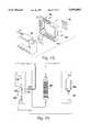
- air supply unit 100basically comprises a housing 101, a blower 159, a manifold assembly 168, air valve tubes 176a-c and related components which make up valves for controlling flow through the valve tubes 176a-c, a potentiometer 185, power switch 157 and its related components, power cord 154, and controller 177.
- the blower 159is a conventional blower manufactured by Ametek-Lamb in the preferred embodiment.
- a blower damping disk 160 and a blower acoustical foam donut 161are adhesively bonded to blower 159.
- blower 159is surrounded by an acoustical foam enclosure comprising elements 167 (FIG. 7A) and 187 (FIG. 7B).
- Blower unit 159is secured by means of rubber-like connectors 165 which further isolate and reduce blower vibration and related noise.
- Connectors 165themselves are threadably or adhesively secured to mounting ears 150 formed integral with blower 159, and corresponding screws 164 threadably secure connectors 165 to blower mounting bracket 163.
- the blower mounting bracket 163is then firmly secured to the interior walls of front housing half 101', preferably by trapping flanges 163' and 163" along the edges of bracket 163 in a captive groove that is formed by joining halves 101' and 101" of housing 101.
- a control cable 183is electrically connected to blower 159 for controlling the operation thereof based on power distributed and controlled by controller 177.
- the pressure outlet 162 of blower 159is connected through hole 167' of acoustical insulation 167 into sealed engagement with an inlet opening 268 in manifold assembly 168. Such sealed engagement is aided by grommet 268a in a conventional manner. Air flows freely from the inlet 268 of manifold assembly 168 to each of its outlets 168', 168" and 168"' so that the pressure at each of those outlets is essentially the same.
- a heating element(described further herein) is provided within manifold assembly 168 for uniformly warming air passing through assembly 168 between inlet 268 and each of outlets 168', 168" and 168"'.
- Each of outlets 168'-168"'are connected in fluid communication with valve tubes 176a-176c, respectively, and thence, corresponding openings 166a-166c in air outlet panel 174.
- Chassis 170is secured to housing 101 between the manifold assembly 168 and outlet panel 174 to help maintain positioning of valve tubes 176a-c while also ensuring proper operation of the corresponding valves.
- Valve tube 176bis in free, unrestricted communication with outlet 166b, whereas each of the valve tubes 176a-176c are associated with valves 194 and 195, respectively, for enabling adjustable restriction of the flow therethrough.
- valves 194 and 195are identical and are of relatively simple construction.
- Valve 194for instance, comprises a valve stem 171 which supports and positions a valve swivel foot 173 in spaced relationship with an opposing wall 170' of chassis 170 for varying the degree of compression of valve tubes 176a-176c.
- Valve stems 171 and 171aare directly engaged with knobs 148 and 150 for enabling manual adjustment thereof.
- one aspect of this inventioninvolves controlling the flow therethrough by controlling the speed of blower 159.
- Rotary knob 149is connected to potentiometer 185 for adjusting the same. Due to unit 100's control circuitry outlined below, adjustment of potentiometer 185, in turn, adjusts the speed of blower 159.
- the potentiometer cable 185'electrically links with controller 177 to contribute to the overall operation of air supply unit 100. Hence, because tube 176b is unrestricted, the flow therethrough is directly controlled based on the adjustment of knob 149.
- the body air flow adjustment knob 149is provided primarily to control the BODY cushion 32, it still controls the blower speed for the whole bed (total air volume to all three cushions 31-33). Therefore, air flow to the BODY cushion 32 is dictated principally only by blower speed, while the HEAD and FEET air flow adjustment knobs 148 and 150 throttle the air flow to achieve the desired pressures in cushions 31 and 33 for the head and feet (respectively) of a patient.
- the BODY cushion 32is positioned to generally support the midsection and thus the seat and the greatest proportion of a patient's weight.
- the pressure control in this embodimenttherefore incorporates an ideal system for minimizing bed 10's energy consumption while also simplifying the construction of air supply unit 100.
- An air flow control knob lock-out 153may be provided to help prevent unauthorized access to and adjustment of knobs 148-150.
- Heater control knob 151is directly mounted to a rotary transducer 152 for adjusting the current to (and hence the temperature output of) a heater element 269 contained within manifold assembly 168.
- heater element 269is a PTC element incorporated in manifold assembly 168 of air supply unit 100 for selectively raising temperature of the air directed into the cushions 31-33 up to approximately 8 to 10 degrees above ambient room temperature.
- a heater control knob 151is located on the top of the air supply unit 100.
- a single temperature thermistor 270is provided to help prevent excessive warming by heater element 269.
- Thermistor 270is placed in an optimum location for preventing excessive warming by inserting it through a small hole 271 drilled into central outlet port 168", which tends to have the greatest air flow therethrough due to the valving arrangement described above.
- Thermister 270is linked in the circuit for heater element 269 via cable 270' and controller 177, to interrupt operation of heater 269 if temperatures in port 168" exceed predetermined levels.
- a thermal fuse 272(FIG. 9) is also provided in the heater cable 184 to interrupt operation of heater 269 in the case of over warming.
- Manifold cable 184is likewise connected between manifold 168 and controller 177.
- Power switch cable 182is also linked to controller 177 to empower controller 177 when switch 157 is actuated and plug 154 is properly plugged into a conventional power outlet.
- Hand control cable 186is connected to a six-pin phone jack 181 that is mounted beneath air outlet panel 174. Phone jack 181 enables expansion of the control capacity of air supply unit 100 by enabling the addition of hand control 200 as shown in FIGS. 9 and 11A-12C, which is linked to controller 177 within air supply unit 100 by means of electrical connection 186.
- FIG. 7Bthe remaining components of air supply unit 100 are readily apparent therein.
- Polyurethane foam insulation 187helps to further reduce noise of the unit and air filter 188 is caged over an opening in the rear of housing shell 101" in the same manner as described in the disclosures of said co-pending application.
- Further understanding of the operation of the air supply unit 100will be evident from an understanding of controller 177 and from a description of the use of hand control 200.
- FIGS. 9, 10, and 11A-11Bshow the electrical schematics for each of the units, together with their interrelationship.
- blower unit 100 and its housing 101will be readily apparent to those of ordinary skill in the art in view of the prior art and in view of Applicant's own co-pending patent application, Ser. Nos. 07/714,379, now U.S. Pat. No. 5,168,589, and 07/798,761, now U.S. Pat. No. D344735, filed Jun. 11 and Nov. 27, 1991.
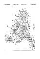
- Frame assembly 20 in the preferred embodimentis a simple, lightweight frame assembly that can be easily disassembled for transport and reassembly through awkward hallways and the like. Except for pan surfaces 21a-c and bracket 290, which are special adaptations, the preferred frame 20 itself (or one substantially the same) is presently commercially available as an 82 inch model KB split-rail frame available through Simmons Healthcare of Norcross, Ga., (formerly Thill, Inc.) or its parent company, Basic American Medical Inc., which has offices in Indianapolis, Ind. and Oshkosh and Fond du Lac, Wisc. The structure and operation of frame assembly 20 will also be readily understood to those of ordinary skill in the field of hospital bed frames from a review of FIGS. 1 and 13-15.
- frame assembly 20basically comprises a caster frame 210, a bed raise-and-lower system 220 (FIG. 14E), a head raise-and-lower system 230 (FIG. 14D), a foot raise-and-control system 240 (FIG. 14F), a foot assembly 250, a head assembly 260, a two-part hinge support 280, and support brackets 281-284 and other connecting members operatively uniting frame assembly 20.
- the head assembly 260, foot assembly 250 and hinge support 280are connected to one another such that certain members such as hinge support 280 and struts 288 and 289 are held in fixed relation to one another.
- Surface supports 321a and 321bare hinged to opposite ends of hinge support 280.
- One end of surface support 321cis hinged to the free end of support 321b, and the other end of support 321c is linked back to strut 288 by a diagonal link 310 which pivots at each of its ends.
- each of the raise-and-lower systems 220, 230 and 240is conventional; for instance, with system 240, a motor 241 operates to turn a screw jack 242 ensleeved within a torque tube 243 to adjust the length of the torque tube 243.
- the torque tube 243is pivotally hinged with a crank arm 244 by pin 244a at the distal end of tube 243, and the crank arm 244 is in turn rigidly connected (i.e., welded) to a transverse member 253 (FIG. 14C) that supports pan surface 21b and support 321b.
- crank arm 244is also pivotally mounted by a second pin 244b to a strut 288 whose position in relation to motor 241 is dictated by mechanical linkage therebetween.
- pan surface 21b and its support 321bare linked to motor 241 in a manner such that operation of motor 241 causes controlled movement of surface 21b.
- pan surface 21a and its support 321aare linked to motor 231 by raise-and lower assembly 230 in a manner such that operation of motor 231 causes controlled movement of surface 21a
- struts 288 and 289are linked to motor 221 in a manner such that operation of motor 221 causes controlled vertical movement of the entire head and foot assemblies 250 and 260 as well as hinge support 280.
- Pan surfaces 21a-care formed as three independent hard pan surfaces which are then welded around their perimeter (or otherwise joined) to their respective supports 321a-c of frame assembly 20, as shown in FIGS. 13-15.
- Pan surfaces 21a-chave slots 22a-c, 23a-c, 24a-d and 25a-d, as well as holes 31a-33a, therethrough for accommodating hoses 151-153 and the various Velcro straps of mattress assembly 50.
- Slots 22a-c and 23a-care particularly suited for securing mattress assembly 50 atop pan surfaces 21a-c, respectively.
- the bed 10is also provided with full-length siderails 70 and 71 that can be adjusted in height to help provide for the safety of the patient in a variety of bed positions.
- Each end of the siderailcan be independently set in one of two elevations to accommodate bed positioning and desires.
- the pendant hand control 200is designed for ease of operation by elderly patients and care givers.
- the hand control 200functions of bed positioning, air flow and air temperature are labeled with large, color-coded, easily recognized graphics as shown in FIG. 12A.
- Large paddle and toggle switches 201-204show clearly which position the controls are set in, and make manipulation of the switches 201-204 easy even for weak patients.
- the hand control 200allows limited patient modification of the air flow and air temperature settings, as well as full control of bed height and head and foot positioning.
- the hand control 200is releasably mounted by means of Velcro strips in a bracket 271 (FIG. 1) on the side rail 71.
- the patientshould not be allowed access to the hand control 200, it can be mounted on the footboard 9b as shown in FIG. 1, out of the patient's line of sight.
- the hand control 200can also be disconnected from the air supply unit 100, removing the capability of remote modification of the initial air flow settings on the air supply unit 100 as well as the ability to adjust bed positions.
- Hand control 200is best understood by distinguishing the upper half 200' and lower half 200" thereof.
- the upper half 200' of hand control 200includes all of the conventional bed frame controls that are commonly found in hospital bed hand controls. For instance, with additional reference to FIGS. 12A-12C, a user of bed 10 would actuate toggle switch 201 to raise or lower the head section 260 of bed 10 (and thereby actuate motor 231 of frame assembly 20), would actuate toggle switch 202 in the "up” or “down” direction to raise or lower (respectively) the hinge support 280 and hence entire pan surface 21a-c (and thereby control motor 221 of frame assembly 20), and would actuate toggle switch 203 to raise or lower the foot section 250 of frame assembly 20 (and thereby actuate motor 241 of frame assembly 20).
- the circuitry corresponding to such functions of toggle switches 201-203is shown in FIG.
- control 200is the only bed electronic controls in the preferred embodiment, although manual adjustment of the bed 10's position is possible.
- the hand control 200has been substituted for the normally available bed control that is standardly provided with bed frame assembly 20 by its manufacturer.
- a patient and/or care giver using hand control 200may adjust the air supply features provided by air control unit 100.
- hand control 200may adjust the air supply features provided by air control unit 100.
- the controls which are integral with air supply unit 100 and frame 20reference is made to the operations thereof. From those operations, those of ordinary skill in the art will readily understand how to make and use the invention as well as the preferred embodiments thereof.
- the effect of using the hand control 200is dependent upon the setting on the air control unit 100 itself. For instance, if air supply unit 100 has been deactuated at switch 157 on the unit itself, the patient cannot then turn the air supply unit on from the hand control 200.
- the patient or care givercan then selectively actuate or deactuate the blower feature provided by air supply unit 100.
- the hand control potentiometers associated with knobs 205' and 206'effectively modify the settings of potentiometers 185 and 152' (shown in FIG. 10), thus modifying the blower speeds and the heating level as provided by air supply unit 100.
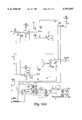
- the circuitry of controller 177is represented schematically in FIG. 10.
- FIG. 10shows the electrical schematic for the blower/heater controller 177 (shown in FIG. 9).
- J1which is the outlet for cable 185' which communicates the setting of potentiometer 185 to controller 177
- J2which is the outlet for connection of cable 186 which links controller 177 to hand control 200
- J3,which is the outlet for connection of cable 183 to controller 177 for enabling electrical communication and power transmission to blower assembly 159
- J4which is the outlet for providing power transmission to heater element 269
- J5which is the outlet of controller 177 for receiving power from power switch 157 via line 182.
- the back side 300 of hand control 200(shown in FIG. 12C) is provided with two strips 207 and 208 of Velcro hook material for enabling releasable mounting of hand control 200 either in siderail bracket 271 or on the outer side of footboard 96 of bed 10 (FIG. 1). Mating strips of Velcro loop material are adhered both in bracket 271 and to the outer side of footboard 96 to further enable this.
- bed 10is intended to be installed in the home setting although bed 10 may be equally beneficial in many other settings.
- frame assembly 20refers to the assembly and disassembly procedure attached hereto as Exhibits A and B and incorporated herein in their entirety by this reference.
- bed 10is especially designed to help provide pressure relief to a patient in the home. It can be disassembled, transported and re-assembled by one person, and can be transported upstairs and through narrow hallways and doorways due to its versatile construction and light-weight components.
- the air cushions 31-33are attached to each other with zippers 61 and 62 and attached to the foam pad 34 below with Velcro straps 63-66.
- the cover sheet 11envelopes the air cushions 31-33 and foam sub-mattress 34 and is held in place by its eight Velcro straps 11a-d looped through slots 24a-d and 25a-d in the hard-pan surfaces 21a-c of frame assembly 20.
- the Velcro straps 11a-dfasten back again onto themselves on the cover sheet 11.
- Conventional bed sheetscan be tucked between the hard-pan surfaces 21a-c of the bed 10 and the magnets 51 sewn into lower sheet 42 of the foam pad cover 40.
- the central connection of the sub-mattress 34 near the lateral center of the hard-pan surfaces 21a-cfurther enables tucking-in of such sheets 44 while still maintaining secure positioning of mattress assembly 50 atop the hard-pan surfaces 21a-c.
- the foam sub-mattress 34is designed to provide pressure reduction for the patient during power outage and to provide comfortable support when the cushions 31-33 are deflated for patients to enter or exit bed 10.
Landscapes
- Health & Medical Sciences (AREA)
- Nursing (AREA)
- Life Sciences & Earth Sciences (AREA)
- Animal Behavior & Ethology (AREA)
- General Health & Medical Sciences (AREA)
- Public Health (AREA)
- Veterinary Medicine (AREA)
- Invalid Beds And Related Equipment (AREA)
Abstract
Description
Claims (5)
Priority Applications (1)
| Application Number | Priority Date | Filing Date | Title |
|---|---|---|---|
| US08/608,996US5594963A (en) | 1992-08-20 | 1996-03-11 | Pressure relief air mattress and related system |
Applications Claiming Priority (3)
| Application Number | Priority Date | Filing Date | Title |
|---|---|---|---|
| US93287392A | 1992-08-20 | 1992-08-20 | |
| US30955794A | 1994-09-20 | 1994-09-20 | |
| US08/608,996US5594963A (en) | 1992-08-20 | 1996-03-11 | Pressure relief air mattress and related system |
Related Parent Applications (1)
| Application Number | Title | Priority Date | Filing Date |
|---|---|---|---|
| US30955794AContinuation | 1992-08-20 | 1994-09-20 |
Publications (1)
| Publication Number | Publication Date |
|---|---|
| US5594963Atrue US5594963A (en) | 1997-01-21 |
Family
ID=26976888
Family Applications (1)
| Application Number | Title | Priority Date | Filing Date |
|---|---|---|---|
| US08/608,996Expired - LifetimeUS5594963A (en) | 1992-08-20 | 1996-03-11 | Pressure relief air mattress and related system |
Country Status (1)
| Country | Link |
|---|---|
| US (1) | US5594963A (en) |
Cited By (45)
| Publication number | Priority date | Publication date | Assignee | Title |
|---|---|---|---|---|
| US5794288A (en)* | 1996-06-14 | 1998-08-18 | Hill-Rom, Inc. | Pressure control assembly for an air mattress |
| US5944494A (en)* | 1997-04-29 | 1999-08-31 | Hill-Rom, Inc. | Blower apparatus mounted in a housing without a rigid connection |
| WO1999049761A1 (en) | 1998-03-31 | 1999-10-07 | Hill-Rom, Inc. | Air-over-foam mattress |
| US6269505B1 (en) | 1999-04-20 | 2001-08-07 | M.P.L. Ltd. | Inflatable cushioning device with manifold system |
| US6378152B1 (en)* | 1995-11-30 | 2002-04-30 | Hill-Rom Services, Inc. | Mattress structure |
| USD457501S1 (en) | 2001-03-26 | 2002-05-21 | Sunflower Medical, L.L.C. | Air mattress control unit |
| US20020129448A1 (en)* | 2001-03-19 | 2002-09-19 | Shahzad Pirzada | Active fluid channeling system for a bed |
| US20020133877A1 (en)* | 2000-12-08 | 2002-09-26 | Kuiper Hendrik Klaas | Portable patient turning and lifting device |
| US6460209B1 (en) | 1995-11-30 | 2002-10-08 | Hill-Rom Services, Inc. | Mattress structure |
| US20020148046A1 (en)* | 2001-03-19 | 2002-10-17 | Shahzad Pirzada | Fluid filled support with a portable pressure adjusting device |
| US6467111B1 (en)* | 2000-03-13 | 2002-10-22 | Kci Licensing, Inc. | Medical bed system with interchangeable modules for mattress systems and related methods |
| US6486792B1 (en) | 1998-04-14 | 2002-11-26 | Hill-Rom Services, Inc. | Communication and bed function control apparatus |
| WO2003009796A1 (en)* | 2001-07-24 | 2003-02-06 | Kci Licensing, Inc. | Medical bed system with interchangeable modules for mattress systems and related methods |
| US6643875B2 (en) | 2001-11-14 | 2003-11-11 | Aero International Products, Inc. | Inflatable mattress topper |
| US6839929B2 (en) | 2001-12-13 | 2005-01-11 | Hill-Rom Services, Inc. | Self-sealing mattress structure |
| US20050028289A1 (en)* | 2002-08-08 | 2005-02-10 | Reza Hakamiun | Mattress |
| US6855158B2 (en) | 2001-09-11 | 2005-02-15 | Hill-Rom Services, Inc. | Thermo-regulating patient support structure |
| US20050125905A1 (en)* | 1999-04-20 | 2005-06-16 | John Wilkinson | Inflatable cushioning device with manifold system |
| US20050177952A1 (en)* | 2004-02-13 | 2005-08-18 | Wilkinson John W. | Discrete cell body support and method for using the same to provide dynamic massage |
| US20060056616A1 (en)* | 2004-09-10 | 2006-03-16 | Heimbrock Richard H | Hospital telephone and device controller |
| US20060156473A1 (en)* | 2004-12-15 | 2006-07-20 | Chambers Kenith W | Quick connector for multi-media |
| US20060175097A1 (en)* | 2004-09-13 | 2006-08-10 | Shazad Pirzada | Wireless weighing system for a bed |
| US20070006388A1 (en)* | 2005-07-07 | 2007-01-11 | Townsend Bobie K | Inflatable device for turning people on their side and back again |
| US7191482B2 (en) | 1998-05-06 | 2007-03-20 | Hill Rom Services, Inc. | Patient support |
| US20070155208A1 (en)* | 2006-01-03 | 2007-07-05 | Shahzad Pirzada | System, device and process for remotely controlling a medical device |
| US20080028534A1 (en)* | 1999-04-20 | 2008-02-07 | M.P.L. Limited | Mattress having three separate adjustable pressure relief zones |
| US20080120780A1 (en)* | 2006-11-16 | 2008-05-29 | Stryker Corporation | Patient support surface with turn-assist |
| US20090013470A1 (en)* | 2007-05-31 | 2009-01-15 | Richards Sandy M | Pulmonary mattress |
| US7617554B2 (en) | 2002-10-10 | 2009-11-17 | M.P.L. Ltd. | Pressure equalization apparatus |
| US7617555B2 (en) | 1998-05-06 | 2009-11-17 | Hill-Rom Services, Inc. | Patient support surface |
| US20100000018A1 (en)* | 2008-07-04 | 2010-01-07 | Mario Cesar Eleonori | Side Guard for Bed |
| US7849545B2 (en) | 2006-11-14 | 2010-12-14 | Hill-Rom Industries Sa | Control system for hospital bed mattress |
| US20110113562A1 (en)* | 2009-11-16 | 2011-05-19 | Uzzle Thomas E | Endboard for person support apparatus |
| US8789224B2 (en) | 2000-11-07 | 2014-07-29 | Tempur-Pedic Managemant, LLC | Therapeutic mattress assembly |
| WO2015095692A1 (en) | 2013-12-20 | 2015-06-25 | Axcelis Technologies, Inc. | Reduced trace metals contamination ion source for an ion implantation system |
| WO2016014897A1 (en)* | 2014-07-25 | 2016-01-28 | Huntleigh Technology Limited | A system and method to physically and electronically configure an air mattress system for multiple users |
| US9462893B2 (en) | 1998-05-06 | 2016-10-11 | Hill-Rom Services, Inc. | Cover system for a patient support surface |
| US9504620B2 (en) | 2014-07-23 | 2016-11-29 | American Sterilizer Company | Method of controlling a pressurized mattress system for a support structure |
| US9757299B2 (en) | 2012-04-16 | 2017-09-12 | Allen Medical Sytems, Inc. | Dual column surgical support system |
| US20180289174A1 (en)* | 2017-04-10 | 2018-10-11 | Hill-Rom Services, Inc. | Mattress overlay for p&v, turn assist and mcm |
| US10363182B2 (en) | 2014-07-14 | 2019-07-30 | Hill-Rom Services, Inc. | Patient control arm with phone dock and head of bed lockout |
| US10548793B2 (en) | 2016-06-14 | 2020-02-04 | Allen Medical Systems, Inc. | Pinless loading for spine table |
| US10575654B2 (en) | 2016-10-28 | 2020-03-03 | Sleep Number Corporation | Air manifold |
| US10993546B2 (en) | 2016-10-28 | 2021-05-04 | Sleep Number Corporation | Noise reducing plunger |
| US11832728B2 (en) | 2021-08-24 | 2023-12-05 | Sleep Number Corporation | Controlling vibration transmission within inflation assemblies |
Citations (15)
| Publication number | Priority date | Publication date | Assignee | Title |
|---|---|---|---|---|
| GB969367A (en)* | 1962-03-05 | 1964-09-09 | George Ingram | Improvements in inflatable mattresses, pillows and cushions |
| CA879575A (en)* | 1971-08-31 | C. Stuart James | Compartmented air mattress | |
| US3644950A (en)* | 1969-08-01 | 1972-02-29 | Milton Roy Co | Patient support system |
| GB1545806A (en)* | 1976-09-23 | 1979-05-16 | Hopkins L | Fluid mattresses |
| US4394784A (en)* | 1981-07-08 | 1983-07-26 | Dial-A-Firm International, Inc. | Air bed with firmness control |
| US4694520A (en)* | 1986-01-15 | 1987-09-22 | Ssi Medical Services, Inc. | Patient support apparatus |
| US4797962A (en)* | 1986-11-05 | 1989-01-17 | Air Plus, Inc. | Closed loop feedback air supply for air support beds |
| US4896389A (en)* | 1988-06-10 | 1990-01-30 | S.S.I. Medical Services Of Canada Inc. | Inflatable air mattress |
| US4949412A (en)* | 1986-11-05 | 1990-08-21 | Air Plus, Inc. | Closed loop feedback air supply for air support beds |
| US5022110A (en)* | 1989-04-17 | 1991-06-11 | Kinetic Concepts, Inc. | Low air loss mattress |
| US5090077A (en)* | 1991-01-07 | 1992-02-25 | Health Products, Inc. | Cellular patient support for therapeutic air beds |
| US5121512A (en)* | 1989-01-03 | 1992-06-16 | Irene Kaufmann | Auxiliary inflatable device serving as mattress |
| US5168589A (en)* | 1989-04-17 | 1992-12-08 | Kinetic Concepts, Inc. | Pressure reduction air mattress and overlay |
| US5182826A (en)* | 1989-03-09 | 1993-02-02 | Ssi Medical Services, Inc. | Method of blower control |
| US5267364A (en)* | 1992-08-11 | 1993-12-07 | Kinetic Concepts, Inc. | Therapeutic wave mattress |
- 1996
- 1996-03-11USUS08/608,996patent/US5594963A/ennot_activeExpired - Lifetime
Patent Citations (15)
| Publication number | Priority date | Publication date | Assignee | Title |
|---|---|---|---|---|
| CA879575A (en)* | 1971-08-31 | C. Stuart James | Compartmented air mattress | |
| GB969367A (en)* | 1962-03-05 | 1964-09-09 | George Ingram | Improvements in inflatable mattresses, pillows and cushions |
| US3644950A (en)* | 1969-08-01 | 1972-02-29 | Milton Roy Co | Patient support system |
| GB1545806A (en)* | 1976-09-23 | 1979-05-16 | Hopkins L | Fluid mattresses |
| US4394784A (en)* | 1981-07-08 | 1983-07-26 | Dial-A-Firm International, Inc. | Air bed with firmness control |
| US4694520A (en)* | 1986-01-15 | 1987-09-22 | Ssi Medical Services, Inc. | Patient support apparatus |
| US4797962A (en)* | 1986-11-05 | 1989-01-17 | Air Plus, Inc. | Closed loop feedback air supply for air support beds |
| US4949412A (en)* | 1986-11-05 | 1990-08-21 | Air Plus, Inc. | Closed loop feedback air supply for air support beds |
| US4896389A (en)* | 1988-06-10 | 1990-01-30 | S.S.I. Medical Services Of Canada Inc. | Inflatable air mattress |
| US5121512A (en)* | 1989-01-03 | 1992-06-16 | Irene Kaufmann | Auxiliary inflatable device serving as mattress |
| US5182826A (en)* | 1989-03-09 | 1993-02-02 | Ssi Medical Services, Inc. | Method of blower control |
| US5022110A (en)* | 1989-04-17 | 1991-06-11 | Kinetic Concepts, Inc. | Low air loss mattress |
| US5168589A (en)* | 1989-04-17 | 1992-12-08 | Kinetic Concepts, Inc. | Pressure reduction air mattress and overlay |
| US5090077A (en)* | 1991-01-07 | 1992-02-25 | Health Products, Inc. | Cellular patient support for therapeutic air beds |
| US5267364A (en)* | 1992-08-11 | 1993-12-07 | Kinetic Concepts, Inc. | Therapeutic wave mattress |
Cited By (82)
| Publication number | Priority date | Publication date | Assignee | Title |
|---|---|---|---|---|
| US6460209B1 (en) | 1995-11-30 | 2002-10-08 | Hill-Rom Services, Inc. | Mattress structure |
| US6378152B1 (en)* | 1995-11-30 | 2002-04-30 | Hill-Rom Services, Inc. | Mattress structure |
| US6952852B2 (en) | 1995-11-30 | 2005-10-11 | Hill-Rom Services, Inc. | Mattress structure |
| US20040133987A1 (en)* | 1995-11-30 | 2004-07-15 | Reeder Ryan A. | Mattress structure |
| US6687935B2 (en) | 1995-11-30 | 2004-02-10 | Hill-Rom Services, Inc. | Mattress structure |
| US6178578B1 (en) | 1996-06-14 | 2001-01-30 | Hill-Rom, Inc. | Pressure control assembly for an air mattress |
| US5794288A (en)* | 1996-06-14 | 1998-08-18 | Hill-Rom, Inc. | Pressure control assembly for an air mattress |
| US5944494A (en)* | 1997-04-29 | 1999-08-31 | Hill-Rom, Inc. | Blower apparatus mounted in a housing without a rigid connection |
| WO1999049761A1 (en) | 1998-03-31 | 1999-10-07 | Hill-Rom, Inc. | Air-over-foam mattress |
| US6212718B1 (en) | 1998-03-31 | 2001-04-10 | Hill-Rom, Inc | Air-over-foam mattress |
| US6781517B2 (en) | 1998-04-14 | 2004-08-24 | Hill-Rom Services, Inc. | Communication and bed function control apparatus |
| US20050007258A1 (en)* | 1998-04-14 | 2005-01-13 | Moster Jeffrey A. | Communication and bed function control apparatus |
| US6486792B1 (en) | 1998-04-14 | 2002-11-26 | Hill-Rom Services, Inc. | Communication and bed function control apparatus |
| US20070163052A1 (en)* | 1998-05-06 | 2007-07-19 | Romano James J | Patient support |
| US9462893B2 (en) | 1998-05-06 | 2016-10-11 | Hill-Rom Services, Inc. | Cover system for a patient support surface |
| US20100095461A1 (en)* | 1998-05-06 | 2010-04-22 | Romano James J | Patient support surface |
| US7191482B2 (en) | 1998-05-06 | 2007-03-20 | Hill Rom Services, Inc. | Patient support |
| US8601620B2 (en) | 1998-05-06 | 2013-12-10 | Hill-Rom Services, Inc. | Cover system for a patient support surface |
| US7966680B2 (en) | 1998-05-06 | 2011-06-28 | Hill-Rom Services, Inc. | Patient support surface |
| US7480953B2 (en) | 1998-05-06 | 2009-01-27 | Hill-Rom Services, Inc. | Patient support |
| US7617555B2 (en) | 1998-05-06 | 2009-11-17 | Hill-Rom Services, Inc. | Patient support surface |
| US6269505B1 (en) | 1999-04-20 | 2001-08-07 | M.P.L. Ltd. | Inflatable cushioning device with manifold system |
| US20080028534A1 (en)* | 1999-04-20 | 2008-02-07 | M.P.L. Limited | Mattress having three separate adjustable pressure relief zones |
| US6826795B2 (en) | 1999-04-20 | 2004-12-07 | M.P.L. Limited | Inflatable cushioning device with manifold system |
| US8122545B2 (en) | 1999-04-20 | 2012-02-28 | M.P.L. Limited | Inflatable cushioning device with manifold system |
| US20050125905A1 (en)* | 1999-04-20 | 2005-06-16 | John Wilkinson | Inflatable cushioning device with manifold system |
| US10357114B2 (en) | 1999-04-20 | 2019-07-23 | Wcw, Inc. | Inflatable cushioning device with manifold system |
| USRE44584E1 (en)* | 1999-04-20 | 2013-11-12 | M.P.L. Limited | Inflatable cushioning device with manifold system |
| US6467111B1 (en)* | 2000-03-13 | 2002-10-22 | Kci Licensing, Inc. | Medical bed system with interchangeable modules for mattress systems and related methods |
| US8789224B2 (en) | 2000-11-07 | 2014-07-29 | Tempur-Pedic Managemant, LLC | Therapeutic mattress assembly |
| US7007330B2 (en) | 2000-12-08 | 2006-03-07 | Autonurse, Inc. | Portable patient turning and lifting device |
| US20020133877A1 (en)* | 2000-12-08 | 2002-09-26 | Kuiper Hendrik Klaas | Portable patient turning and lifting device |
| US20020148046A1 (en)* | 2001-03-19 | 2002-10-17 | Shahzad Pirzada | Fluid filled support with a portable pressure adjusting device |
| US20020129448A1 (en)* | 2001-03-19 | 2002-09-19 | Shahzad Pirzada | Active fluid channeling system for a bed |
| US6789283B2 (en) | 2001-03-19 | 2004-09-14 | Shahzad Pirzada | Fluid filled support with a portable pressure adjusting device |
| USD457501S1 (en) | 2001-03-26 | 2002-05-21 | Sunflower Medical, L.L.C. | Air mattress control unit |
| AU2001276029B2 (en)* | 2001-07-24 | 2008-01-10 | Huntleigh Technology Limited | Medical bed system with interchangeable modules for mattress systems and related methods |
| WO2003009796A1 (en)* | 2001-07-24 | 2003-02-06 | Kci Licensing, Inc. | Medical bed system with interchangeable modules for mattress systems and related methods |
| US6855158B2 (en) | 2001-09-11 | 2005-02-15 | Hill-Rom Services, Inc. | Thermo-regulating patient support structure |
| US6643875B2 (en) | 2001-11-14 | 2003-11-11 | Aero International Products, Inc. | Inflatable mattress topper |
| US6839929B2 (en) | 2001-12-13 | 2005-01-11 | Hill-Rom Services, Inc. | Self-sealing mattress structure |
| US20050028289A1 (en)* | 2002-08-08 | 2005-02-10 | Reza Hakamiun | Mattress |
| US7617554B2 (en) | 2002-10-10 | 2009-11-17 | M.P.L. Ltd. | Pressure equalization apparatus |
| US7434283B2 (en) | 2004-02-13 | 2008-10-14 | M.P.L. Limited | Discrete cell body support and method for using the same to provide dynamic massage |
| US20050177952A1 (en)* | 2004-02-13 | 2005-08-18 | Wilkinson John W. | Discrete cell body support and method for using the same to provide dynamic massage |
| US20060056616A1 (en)* | 2004-09-10 | 2006-03-16 | Heimbrock Richard H | Hospital telephone and device controller |
| US20060175097A1 (en)* | 2004-09-13 | 2006-08-10 | Shazad Pirzada | Wireless weighing system for a bed |
| US20060156473A1 (en)* | 2004-12-15 | 2006-07-20 | Chambers Kenith W | Quick connector for multi-media |
| US7648392B2 (en)* | 2004-12-15 | 2010-01-19 | Hill-Rom Services, Inc. | Quick connector for multi-media |
| US7464422B2 (en) | 2005-07-07 | 2008-12-16 | Bobie Kenneth Townsend | Inflatable device for turning people on their side and back again |
| US20070006388A1 (en)* | 2005-07-07 | 2007-01-11 | Townsend Bobie K | Inflatable device for turning people on their side and back again |
| US20070155208A1 (en)* | 2006-01-03 | 2007-07-05 | Shahzad Pirzada | System, device and process for remotely controlling a medical device |
| US8015972B2 (en) | 2006-01-03 | 2011-09-13 | Shahzad Pirzada | System, device and process for remotely controlling a medical device |
| US9278183B2 (en) | 2006-01-03 | 2016-03-08 | Shahzad Pirzada | System, device and process for remotely controlling a medical device |
| US7849545B2 (en) | 2006-11-14 | 2010-12-14 | Hill-Rom Industries Sa | Control system for hospital bed mattress |
| US8006333B2 (en) | 2006-11-16 | 2011-08-30 | Stryker Corporation | Patient support surface with turn-assist |
| US20080120780A1 (en)* | 2006-11-16 | 2008-05-29 | Stryker Corporation | Patient support surface with turn-assist |
| US8108957B2 (en) | 2007-05-31 | 2012-02-07 | Hill-Rom Services, Inc. | Pulmonary mattress |
| US8584279B2 (en) | 2007-05-31 | 2013-11-19 | Hill-Rom Services, Inc. | Pulmonary mattress |
| US20090013470A1 (en)* | 2007-05-31 | 2009-01-15 | Richards Sandy M | Pulmonary mattress |
| US20100000018A1 (en)* | 2008-07-04 | 2010-01-07 | Mario Cesar Eleonori | Side Guard for Bed |
| US20110113562A1 (en)* | 2009-11-16 | 2011-05-19 | Uzzle Thomas E | Endboard for person support apparatus |
| US9757299B2 (en) | 2012-04-16 | 2017-09-12 | Allen Medical Sytems, Inc. | Dual column surgical support system |
| US9543110B2 (en) | 2013-12-20 | 2017-01-10 | Axcelis Technologies, Inc. | Reduced trace metals contamination ion source for an ion implantation system |
| WO2015095692A1 (en) | 2013-12-20 | 2015-06-25 | Axcelis Technologies, Inc. | Reduced trace metals contamination ion source for an ion implantation system |
| US11712385B2 (en) | 2014-07-14 | 2023-08-01 | Hill-Rom Services, Inc. | Patient bed having head-of-bed lockout and stay-in-bed indicator |
| US10363182B2 (en) | 2014-07-14 | 2019-07-30 | Hill-Rom Services, Inc. | Patient control arm with phone dock and head of bed lockout |
| US11571347B2 (en) | 2014-07-14 | 2023-02-07 | Hill-Rom Services, Inc. | Patient control arm with phone dock and head-of-bed lockout |
| US9504620B2 (en) | 2014-07-23 | 2016-11-29 | American Sterilizer Company | Method of controlling a pressurized mattress system for a support structure |
| WO2016014897A1 (en)* | 2014-07-25 | 2016-01-28 | Huntleigh Technology Limited | A system and method to physically and electronically configure an air mattress system for multiple users |
| US10470956B2 (en) | 2014-07-25 | 2019-11-12 | Huntleigh Technology Limited | System and method to physically and electronically configure an air mattress system for multiple users |
| US10548793B2 (en) | 2016-06-14 | 2020-02-04 | Allen Medical Systems, Inc. | Pinless loading for spine table |
| US11426006B2 (en) | 2016-10-28 | 2022-08-30 | Sleep Number Corporation | Air manifold |
| US10993546B2 (en) | 2016-10-28 | 2021-05-04 | Sleep Number Corporation | Noise reducing plunger |
| US10575654B2 (en) | 2016-10-28 | 2020-03-03 | Sleep Number Corporation | Air manifold |
| US11937705B2 (en) | 2016-10-28 | 2024-03-26 | Sleep Number Corporation | Air bed system with an air manifold |
| US11950702B2 (en) | 2016-10-28 | 2024-04-09 | Sleep Number Corporation | Noise reducing plunger |
| US12290181B2 (en) | 2016-10-28 | 2025-05-06 | Sleep Number Corporation | Pump and manifold with unvalved vent |
| US10856668B2 (en)* | 2017-04-10 | 2020-12-08 | Hill-Rom Services, Inc. | Mattress overlay control system with rotary valves and graphical user interface for percussion and vibration, turn assist and microclimate management |
| US11684169B2 (en) | 2017-04-10 | 2023-06-27 | Hill-Rom Services, Inc. | Rotary plate valve having seal anti-herniation structure |
| US20180289174A1 (en)* | 2017-04-10 | 2018-10-11 | Hill-Rom Services, Inc. | Mattress overlay for p&v, turn assist and mcm |
| US11832728B2 (en) | 2021-08-24 | 2023-12-05 | Sleep Number Corporation | Controlling vibration transmission within inflation assemblies |
Similar Documents
| Publication | Publication Date | Title |
|---|---|---|
| US5594963A (en) | Pressure relief air mattress and related system | |
| US8201292B2 (en) | Patient support surface with turn-assist | |
| US10507147B2 (en) | Patient support | |
| US9462893B2 (en) | Cover system for a patient support surface | |
| US7966680B2 (en) | Patient support surface | |
| US5168589A (en) | Pressure reduction air mattress and overlay | |
| US5647079A (en) | Inflatable patient support surface system | |
| US8006333B2 (en) | Patient support surface with turn-assist | |
| US7480953B2 (en) | Patient support | |
| EP0688173B1 (en) | Air support device | |
| EP1424921B1 (en) | Bed with adjustable elevation components | |
| US7155766B1 (en) | Bolster system and method | |
| US20070101504A1 (en) | Bolster system and method | |
| CN205913485U (en) | Air mattress | |
| EP2086492B1 (en) | A patient support surface with turn-assist | |
| AU2012202878B2 (en) | Patient support | |
| JPS63183056A (en) | Fluid bed for hospital |
Legal Events
| Date | Code | Title | Description |
|---|---|---|---|
| STCF | Information on status: patent grant | Free format text:PATENTED CASE | |
| AS | Assignment | Owner name:BANK OF AMERICA NATIONAL TRUST AND SAVINGS ASSOCIA Free format text:SECURITY AGREEMENT;ASSIGNORS:KINETIC CONCEPTS, INC. (A TEXAS CORPORATION);KCI HOLDING COMPANY, (A DE CORP.);KCI NEW TECHNOLOGIES, INC. (A DE CORP.);AND OTHERS;REEL/FRAME:008896/0699 Effective date:19971103 | |
| FPAY | Fee payment | Year of fee payment:4 | |
| AS | Assignment | Owner name:KCI LICENSING, INC., TEXAS Free format text:ASSIGNMENT OF ASSIGNORS INTEREST;ASSIGNOR:KINETIC CONCEPTS, INC.;REEL/FRAME:012219/0150 Effective date:20010919 | |
| AS | Assignment | Owner name:KINETIC CONCEPTS, INC., TEXAS Free format text:ASSIGNMENT OF ASSIGNORS INTEREST;ASSIGNOR:BERKOWITZ, STEVEN A.;REEL/FRAME:013949/0010 Effective date:19920820 | |
| AS | Assignment | Owner name:MORGAN STANLEY & CO. INCORPORATED, NEW YORK Free format text:SECURITY INTEREST;ASSIGNORS:KINETIC CONCEPTS, INC.;KCI USA, INC.;KCI HOLDING COMPANY, INC.;AND OTHERS;REEL/FRAME:014624/0681 Effective date:20030811 | |
| FPAY | Fee payment | Year of fee payment:8 | |
| AS | Assignment | Owner name:KCI LICENSING, INC., TEXAS Free format text:RELEASE BY SECURED PARTY;ASSIGNOR:BANK OF AMERICA NATIONAL TRUST & SAVINGS ASSOCIATION;REEL/FRAME:019605/0526 Effective date:20070727 | |
| AS | Assignment | Owner name:KCI LICENSING, INC., TEXAS Free format text:RELEASE BY SECURED PARTY;ASSIGNOR:MORGAN STANLEY & CO., INCORPORATED;REEL/FRAME:019617/0356 Effective date:20070731 Owner name:KCI LICENSING, INC.,TEXAS Free format text:RELEASE BY SECURED PARTY;ASSIGNOR:MORGAN STANLEY & CO., INCORPORATED;REEL/FRAME:019617/0356 Effective date:20070731 | |
| AS | Assignment | Owner name:CITIBANK, N.A., AS ADMINISTRATIVE AGENT, DELAWARE Free format text:SECURITY AGREEMENT;ASSIGNORS:KCI LICENSING, INC.;KINETIC CONCEPTS, INC.;KCI USA, INC.;AND OTHERS;REEL/FRAME:019640/0163 Effective date:20070731 Owner name:CITIBANK, N.A., AS ADMINISTRATIVE AGENT,DELAWARE Free format text:SECURITY AGREEMENT;ASSIGNORS:KCI LICENSING, INC.;KINETIC CONCEPTS, INC.;KCI USA, INC.;AND OTHERS;REEL/FRAME:019640/0163 Effective date:20070731 | |
| AS | Assignment | Owner name:BANK OF AMERICA, N.A., ILLINOIS Free format text:SECURITY AGREEMENT;ASSIGNORS:KINETIC CONCEPTS, INC.;KCI LICENSING, INC.;REEL/FRAME:021006/0847 Effective date:20080519 Owner name:BANK OF AMERICA, N.A.,ILLINOIS Free format text:SECURITY AGREEMENT;ASSIGNORS:KINETIC CONCEPTS, INC.;KCI LICENSING, INC.;REEL/FRAME:021006/0847 Effective date:20080519 | |
| AS | Assignment | Owner name:KINETIC CONCEPTS, INC., TEXAS Free format text:RELEASE BY SECURED PARTY;ASSIGNOR:CITIBANK, N.A.;REEL/FRAME:021018/0130 Effective date:20080515 Owner name:KCI USA, INC., TEXAS Free format text:RELEASE BY SECURED PARTY;ASSIGNOR:CITIBANK, N.A.;REEL/FRAME:021018/0130 Effective date:20080515 Owner name:KCI HOLDING COMPANY, INC., TEXAS Free format text:RELEASE BY SECURED PARTY;ASSIGNOR:CITIBANK, N.A.;REEL/FRAME:021018/0130 Effective date:20080515 Owner name:KCI LICENSING, INC., TEXAS Free format text:RELEASE BY SECURED PARTY;ASSIGNOR:CITIBANK, N.A.;REEL/FRAME:021018/0130 Effective date:20080515 Owner name:KCI INTERNATIONAL, INC., TEXAS Free format text:RELEASE BY SECURED PARTY;ASSIGNOR:CITIBANK, N.A.;REEL/FRAME:021018/0130 Effective date:20080515 Owner name:KINETIC CONCEPTS, INC.,TEXAS Free format text:RELEASE BY SECURED PARTY;ASSIGNOR:CITIBANK, N.A.;REEL/FRAME:021018/0130 Effective date:20080515 Owner name:KCI USA, INC.,TEXAS Free format text:RELEASE BY SECURED PARTY;ASSIGNOR:CITIBANK, N.A.;REEL/FRAME:021018/0130 Effective date:20080515 Owner name:KCI HOLDING COMPANY, INC.,TEXAS Free format text:RELEASE BY SECURED PARTY;ASSIGNOR:CITIBANK, N.A.;REEL/FRAME:021018/0130 Effective date:20080515 Owner name:KCI LICENSING, INC.,TEXAS Free format text:RELEASE BY SECURED PARTY;ASSIGNOR:CITIBANK, N.A.;REEL/FRAME:021018/0130 Effective date:20080515 Owner name:KCI INTERNATIONAL, INC.,TEXAS Free format text:RELEASE BY SECURED PARTY;ASSIGNOR:CITIBANK, N.A.;REEL/FRAME:021018/0130 Effective date:20080515 | |
| FPAY | Fee payment | Year of fee payment:12 | |
| AS | Assignment | Owner name:LIFECELL CORPORATION, TEXAS Free format text:TERMINATION OF SECURITY INTEREST IN PATENTS;ASSIGNOR:BANK OF AMERICA, N.A., AS ADMINISTRATIVE AGENT;REEL/FRAME:025599/0904 Effective date:20110107 Owner name:KCI LICENSING, INC., TEXAS Free format text:TERMINATION OF SECURITY INTEREST IN PATENTS;ASSIGNOR:BANK OF AMERICA, N.A., AS ADMINISTRATIVE AGENT;REEL/FRAME:025599/0904 Effective date:20110107 Owner name:KINETIC CONCEPTS, INC., TEXAS Free format text:TERMINATION OF SECURITY INTEREST IN PATENTS;ASSIGNOR:BANK OF AMERICA, N.A., AS ADMINISTRATIVE AGENT;REEL/FRAME:025599/0904 Effective date:20110107 | |
| AS | Assignment | Owner name:BANK OF AMERICA, N.A., AS COLLATERAL AGENT, NORTH CAROLINA Free format text:SECURITY AGREEMENT;ASSIGNORS:KCI LICENSING, INC.;LIFECELL CORPORATION;TECHNIMOTION, LLC;REEL/FRAME:027185/0174 Effective date:20111104 Owner name:BANK OF AMERICA, N.A., AS COLLATERAL AGENT, NORTH Free format text:SECURITY AGREEMENT;ASSIGNORS:KCI LICENSING, INC.;LIFECELL CORPORATION;TECHNIMOTION, LLC;REEL/FRAME:027185/0174 Effective date:20111104 | |
| AS | Assignment | Owner name:WILMINGTON TRUST, NATIONAL ASSOCIATION, AS COLLATERAL AGENT, MINNESOTA Free format text:SECURITY AGREEMENT;ASSIGNORS:KCI LICENSING, INC.;LIFECELL CORPORATION;TECHNIMOTION, LLC;REEL/FRAME:027194/0447 Effective date:20111104 Owner name:WILMINGTON TRUST, NATIONAL ASSOCIATION, AS COLLATE Free format text:SECURITY AGREEMENT;ASSIGNORS:KCI LICENSING, INC.;LIFECELL CORPORATION;TECHNIMOTION, LLC;REEL/FRAME:027194/0447 Effective date:20111104 | |
| AS | Assignment | Owner name:KINETIC CONCEPTS, INC., TEXAS Free format text:RELEASE BY SECURED PARTY;ASSIGNOR:WILMINGTON TRUST;REEL/FRAME:040098/0200 Effective date:20160920 Owner name:KCI LICENSING, INC., TEXAS Free format text:RELEASE BY SECURED PARTY;ASSIGNOR:WILMINGTON TRUST;REEL/FRAME:040098/0200 Effective date:20160920 Owner name:LIFECELL CORPORATION, TEXAS Free format text:RELEASE BY SECURED PARTY;ASSIGNOR:WILMINGTON TRUST;REEL/FRAME:040098/0200 Effective date:20160920 Owner name:TECHNIMOTION, LLC, TEXAS Free format text:RELEASE BY SECURED PARTY;ASSIGNOR:WILMINGTON TRUST;REEL/FRAME:040098/0200 Effective date:20160920 | |
| AS | Assignment | Owner name:TECHNIMOTION, LLC, A DELAWARE LIMITED LIABILITY COMPANY, AS GRANTOR, TEXAS Free format text:RELEASE OF SECURITY INTEREST IN INTELLECTUAL PROPERTY;ASSIGNOR:BANK OF AMERICA, N.A., AS COLLATERAL AGENT;REEL/FRAME:041395/0044 Effective date:20170203 Owner name:SYSTAGENIX WOUND MANAGEMENT (US), INC., A DELAWARE CORPORATION, AS GRANTOR, TEXAS Free format text:RELEASE OF SECURITY INTEREST IN INTELLECTUAL PROPERTY;ASSIGNOR:BANK OF AMERICA, N.A., AS COLLATERAL AGENT;REEL/FRAME:041395/0044 Effective date:20170203 Owner name:TECHNIMOTION, LLC, A DELAWARE LIMITED LIABILITY CO Free format text:RELEASE OF SECURITY INTEREST IN INTELLECTUAL PROPERTY;ASSIGNOR:BANK OF AMERICA, N.A., AS COLLATERAL AGENT;REEL/FRAME:041395/0044 Effective date:20170203 Owner name:KCI LICENSING, INC., AS GRANTOR, TEXAS Free format text:RELEASE OF SECURITY INTEREST IN INTELLECTUAL PROPERTY;ASSIGNOR:BANK OF AMERICA, N.A., AS COLLATERAL AGENT;REEL/FRAME:041395/0044 Effective date:20170203 Owner name:SYSTAGENIX WOUND MANAGEMENT (US), INC., A DELAWARE Free format text:RELEASE OF SECURITY INTEREST IN INTELLECTUAL PROPERTY;ASSIGNOR:BANK OF AMERICA, N.A., AS COLLATERAL AGENT;REEL/FRAME:041395/0044 Effective date:20170203 |