US5594813A - Programmable architecture and methods for motion estimation - Google Patents
Programmable architecture and methods for motion estimationDownload PDFInfo
- Publication number
- US5594813A US5594813AUS07/838,380US83838092AUS5594813AUS 5594813 AUS5594813 AUS 5594813AUS 83838092 AUS83838092 AUS 83838092AUS 5594813 AUS5594813 AUS 5594813A
- Authority
- US
- United States
- Prior art keywords
- memory
- pixels
- block
- pixel
- search
- Prior art date
- Legal status (The legal status is an assumption and is not a legal conclusion. Google has not performed a legal analysis and makes no representation as to the accuracy of the status listed.)
- Expired - Lifetime
Links
Images


Classifications
- H—ELECTRICITY
- H04—ELECTRIC COMMUNICATION TECHNIQUE
- H04N—PICTORIAL COMMUNICATION, e.g. TELEVISION
- H04N5/00—Details of television systems
- H04N5/14—Picture signal circuitry for video frequency region
- H04N5/144—Movement detection
- H04N5/145—Movement estimation
- G—PHYSICS
- G06—COMPUTING OR CALCULATING; COUNTING
- G06T—IMAGE DATA PROCESSING OR GENERATION, IN GENERAL
- G06T7/00—Image analysis
- G06T7/20—Analysis of motion
- G06T7/223—Analysis of motion using block-matching
- G06T7/231—Analysis of motion using block-matching using full search
- H—ELECTRICITY
- H04—ELECTRIC COMMUNICATION TECHNIQUE
- H04N—PICTORIAL COMMUNICATION, e.g. TELEVISION
- H04N19/00—Methods or arrangements for coding, decoding, compressing or decompressing digital video signals
- H04N19/42—Methods or arrangements for coding, decoding, compressing or decompressing digital video signals characterised by implementation details or hardware specially adapted for video compression or decompression, e.g. dedicated software implementation
- H04N19/43—Hardware specially adapted for motion estimation or compensation
- H04N19/433—Hardware specially adapted for motion estimation or compensation characterised by techniques for memory access
- H—ELECTRICITY
- H04—ELECTRIC COMMUNICATION TECHNIQUE
- H04N—PICTORIAL COMMUNICATION, e.g. TELEVISION
- H04N19/00—Methods or arrangements for coding, decoding, compressing or decompressing digital video signals
- H04N19/50—Methods or arrangements for coding, decoding, compressing or decompressing digital video signals using predictive coding
- H04N19/503—Methods or arrangements for coding, decoding, compressing or decompressing digital video signals using predictive coding involving temporal prediction
- H04N19/51—Motion estimation or motion compensation
- H04N19/523—Motion estimation or motion compensation with sub-pixel accuracy
- G—PHYSICS
- G06—COMPUTING OR CALCULATING; COUNTING
- G06T—IMAGE DATA PROCESSING OR GENERATION, IN GENERAL
- G06T2207/00—Indexing scheme for image analysis or image enhancement
- G06T2207/10—Image acquisition modality
- G06T2207/10016—Video; Image sequence
Definitions
- the present inventionrelates generally to motion estimation, and more specifically to a programmable architecture and methods for motion vector and/or prediction error determination.
- a standard for digital television broadcast coding at 30/45 Mb/sis under consideration; see CCIR-CMTT/2, "Digital Transmission of Component-Coded Television Signals at 30-34 Mb/s and 45 Mb/s Using the Discrete Cosine Transform," Document CMTT/2-55.
- a standard for video telephony and video conferencing at 64 to 1920 kb/shas been adopted by the International Consultative Committee for Telephone and Circuit ("CCITT"); see “Draft Revision of Recommendation H.261," Document 572, CCITT SG XV, Working Party XV/1, Spec. Grp. on Coding for Visual Telephony.
- MPEGMoving Picture Experts Group
- Video coding algorithmshave been proposed as contributions to the standardization activity of ISO/MPEG; see Wong et al., "MCPIC: A Video Coding Algorithm for Transmission and Storage Applications," IEEE Communications Magazine, November 1990, pp. 24-32.
- Many video coding techniquesinclude a predictive mode that realizes data compression between two different video frames by identifying how a frame is unlike a preceding frame.
- the frameis represented in terms of a set of vectors of the displacement of respective groups of pixels in the frame relative to their position in the preceding frame, known as motion vectors; and difference information representing the degree of difference between the displaced pixels and the corresponding pixels in the preceding frame.
- motion vectorsthe difference information representing the degree of difference between the displaced pixels and the corresponding pixels in the preceding frame.
- the present inventionis advantageous in many respects.
- the programmability aspect of the present inventionenables support of future algorithms, and allows the addition of customer-proprietary optimizations and algorithms.
- an apparatus for performing an arithmetic operation on groups of pixels under program controlhaving two memories and an arithmetic unit.
- One of the memorieshas a plurality of addressable locations N pixels in width and a read port, and N pixels from any one of the addressable locations are accessible in parallel on the read port during an address cycle.
- the other memoryhas a plurality of addressable locations greater than N pixels in width and a read port, and any N contiguous pixels from any one of the addressable locations are accessible in parallel on the read port during an address cycle.
- the arithmetic unitis connected to the two memory ports.
- a memoryin another embodiment, has a plurality of addressable locations greater than N pixels in width and two read ports, and any N contiguous pixels from any one of the addressable locations are accessible in parallel on each of the read ports during an address cycle.
- the arithmetic unitis connected to the two ports.
- a memory arrayhas a plurality of addressable locations N pixels in width and a read port, and N pixels from any one of the addressable locations and N pixels from an adjacent addressable location are accessible in parallel on the read port during an address cycle.
- a shifterhas its input coupled to the read port, and provides N pixels on its output.
- groups of pixelsare read from two memory ports, at least one of which is pixel-group random addressable, and used to determine sums of absolute differences, pixel differences, and pixel averages.
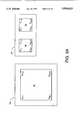
- FIG. 1is a schematic diagram showing the relationship between an image block and search blocks within a search window
- FIG. 2is a block diagram showing a motion estimation architecture in accordance with the present invention.
- FIG. 3Ais a block diagram representing a memory arrangement for full pixel motion estimation
- FIG. 3Bis a block diagram representing a memory arrangement for one-half and one-quarter pixel interpolation
- FIGS. 4 and 5are pictorial representations of full pixel positions of a search matrix and their relationship to interpolated pixels at one-half and one-quarter pixel displacements;
- FIGS. 6 and 7are schematic representations of the configuration of various memories in the architecture of FIG. 2;
- FIG. 8is a block diagram of an address generator
- FIG. 9is a block schematic diagram of a pixel-group random access memory useful in the datapath of the architecture of FIG. 2;
- FIGS. 10A and 10Bare a schematic representation of a portion of the pixel-group random access memory of FIG. 9;
- FIGS. 11A-11Dare a block schematic diagram of a funnel shifter and transpose network useful in the datapath of the architecture of FIG. 2;
- FIG. 12is a schematic representation of the pixel-group random access memory of FIG. 9 useful in explaining the operation of the funnel shifter of FIG. 11;
- FIG. 13is a block schematic diagram of another memory useful in the datapath of the architecture of FIG. 2;
- FIG. 14is a block schematic diagram of an arithmetic logic unit useful in the datapath of the architecture of FIG. 2.
- Motion vector searchingtypically involves comparing an input or image block with search blocks within a search window centered on the frame location of the image block.
- the image block 12 shown in FIG. 1is obtained, for example, from a video input device 10, which may be a video camera, video transmission, preframe video memory, or the like.
- the image block 12may be any convenient size; 16 ⁇ 16 pixels is exemplary.
- the search window 24is obtained typically from a frame memory 20, in which a previously processed frame is stored.
- the search window 24is approximately centered on the location of the image block 12.
- the search block 22shown in solid line
- the search blocks of the search window 24are generally of the same size as the image block 12.
- the search window 24is defined by an illustrative displacement of the search block 22 eight pixels to the left (block 26.1, outlined in a fine phantom line) and seven pixels to the right (block 26.2, outlined in a coarse phantom line), seven pixels up, and eight pixels down.
- the size of the search window 24 for a full pixel searchis 31 ⁇ 31. A larger search window 24 may be used if more memory is available.
- the image block 12is successively compared in comparator 30 with the search blocks in the search window 24, and is represented for storage or transmission by displacement data, or motion vectors, and by difference information, or prediction error data, based on the closest matching search block in the search window 24.
- luminance informationis used for motion vector searching.
- the size of the basic luminance information unitis somewhat discretionary, and generally depends on the application and design choice.
- the basic video information processing unit, or macroblockis a 16 ⁇ 16 pixel luminance matrix.
- FIG. 2An illustrative programmable architecture 100 for implementing motion vector searching is illustrated in FIG. 2. Rapid and efficient motion vector searching is accommodated by two high-speed, multi-ported register files in the datapath of the architecture 100: an image block, best match block memory conveniently referred to as DP memory 124, and a search memory conveniently referred to as DPCM memory 130.
- the memories 124 and 130are configured in an advantageous manner based on the desired video information block size and on the critical operations required of the architecture 100 in executing certain widely accepted current standards and possible future standards.
- Other important data path elements for motion vector estimationinclude two funnel shifters 140 and 144, an arithmetic logic unit (“ALU") 154, and a tree adder 156. Shifter 140 is connected to port A of the DPCM memory 130, and shifter 144 is connected to port B of the DPCM memory 130.
- ALU 154receives pixel data items from shifters 140 and 144 and from the DP memory 124.
- the video information stored in the DP memory 124 and the DPCM memory 130are stored as blocks.
- a basic configuration for an motion vector searching on an integral full pixel basisis shown in FIG. 3A.
- Two blocksare stored in the DP memory 124, a "P" or preframe block 80 and a "D" block 82.
- each blockis 16 ⁇ 16 pixels, so that the minimum memory size is 16 ⁇ 32 ⁇ 8 bits, for example.
- the entire search window 24is copied into the DPCM memory 130 from frame memory 20.
- the size of DPCM memory 130need be 31 ⁇ 31 ⁇ 8 bits.
- the best block matchis determined among all search blocks in the search window 24 by a minimum sum of absolute block differences criteria.
- the minimum sum of absolute block differences of expression (1)is implemented in the architecture of FIG. 2 as follows, although other implementations may be realized.
- the image block 12is read into the P block 80, while the entire search window 24 is read from an external memory (not shown) into the DPCM memory 130, overwriting any previously stored search window.
- the differences between the pixels stored in P block 80 and the current search blockis determined in ALU 154, and summed by tree adder 156. Two hundred fifty-six differences are computed per each sum.
- the sum for the current search blockis compare with the minimum sum of absolute block differences stored in a register (not shown) in controller 102, and substituted therefor if less, along with the search block identity.
- the motion vectoris known simply from the spatial identity of the best match block, while the prediction error is determined as follows.
- the prediction erroris the difference between the best match block stored relative to location W Xb ,Yb and the image block stored in P block 80, or
- the search area for the next preframe blocktypically overlaps with the search area of the current preframe block.
- the preframe block sizeis 16 ⁇ 16
- this techniquebecomes increasingly useful for reducing the external memory bandwidth requirements and overall system cost.
- the PRAM (Pixel-group Random Access Memory) addressing modeallows addressing the DPCM memory 130 in such a way that any random N contiguous pixels can be accessed in parallel from a memory array of size greater than N pixels in width. It will be appreciated that a minor additional complexity introduced by bringing in only part of the new search area is that the starting address of the search area shifts by a fixed amount in the horizontal direction.
- the DPCM memory 130is used to store a search window 24 that is in large part an interpolated search matrix generated from a best match search block from a less accurate estimation operation.
- FIG. 3BA basic configuration of the DP memory 124 and the DPCM memory 130 for half-pixel estimation is shown in FIG. 3B.
- two blocksare stored in the DP memory 124, the P block 80 and the D block 82, and each block is 16 ⁇ 16 pixels. Somewhat more than four blocks are stored in the DPCM memory 130, however.
- An "X" block 70receives the best match search block and surrounding pixels loaded from the frame memory 20 or from the block stored relative to the location W Xb ,Yb.
- "A" block 72, "B” block 74, and "C” block 76are interpolated from the X block 70 and used in half pixel and, later, quarter pixel estimation, as described below.
- the X block 70is 18 ⁇ 18 pixels
- the A block 72is 18 ⁇ 17 pixels
- the B block 74is 17 ⁇ 18 pixels
- the C block 76is 17 ⁇ 17 pixels, so that the preferable minimum memory size of the DPCM memory 130 for half-pixel estimation is 35 ⁇ 35 ⁇ 8 bits, for example.
- FIG. 4A conceptual representation of an illustrative interpolated search matrix 400 is shown in FIG. 4.
- the matrix 400comprises four completely interleaved matrices corresponding to blocks 70, 72, 74 and 76, respectively containing pixels X r ,c, A r ,c, B r ,c, and C r ,c, wherein "r” is the row number and "c" is the column number.
- the number of rows and columns in each of the interleaved X, A, B and C matricesis dependent on the application and to some extent design choice.
- the 16 ⁇ 16 pixels of a best match search block 71 from a motion vector search on an integral full pixel basisare shown as matrix elements X 1 ,1 through X 16 ,16, bounded within the region 402 in FIG. 4 by a double line.
- Pixels X 0 ,0 through X 0 ,17, X 0 ,0 through X 17 ,0, X 17 ,0 through X 17 ,17, and X 0 ,17 through X 17 ,17are adjacent the best match search block 71 and are copied into X block 70 of the DPCM memory 130 to allow interpolation of fractional pixel positions about all of the pixels of the best match search block 71.
- Pixels B r ,c (r0, . . .
- the D block 82 and the P block 80 stored in the DP memory 124are each 16 ⁇ 16 pixels. Block 70 was present during the motion vector search on an integral full pixel basis, and is merely relocated in the DPCM memory 130, to reduce external memory bandwidth.
- the A block 72, the B block 74, and the C block 74are interpolated as follows.
- the A block 72is formed by progressive horizontal interpolations of the X block 70.
- a pixel group from a row of the X block 70is addressed on both ports A and B of the DPCM memory 130. Accordingly, the same pixel group is loaded into both shifters 140 and 144.
- One of the pixel groupsis shifted one pixel; for example, the pixel group in funnel shifter 144 is shifted one pixel, or eight bits, to the right.
- the unshifted output from funnel shifter 140 and the one-pixel right shifted output from the funnel shifter 144are presented to respectively the A and B inputs of the ALU 154, which performs a divide by two and a rounding off.
- the resultis routed from the ALU 154 into appropriate address locations of the A block 74 in the DPCM memory 130. This process is continued until the entire horizontal interpolation of the X block 70 is complete and the entire A block 72
- the B block 74is formed by progressive vertical interpolations of the X block 70.
- a pixel group from a row of the X blockis addressed on port A of the DPCM memory 130, and a pixel group from an immediately adjacent row of the X block 70 having the same column locations is addressed on port B of the DPCM memory 130.
- the pixel groups on ports A and Bpass through funnel shifters 140 and 144 without being shifted, and are presented to respectively the A and B ports of the ALU 154.
- the ALU 154performs a divide by two and a rounding off, and the result is routed into appropriate address locations of the B block of the DPCM memory 130. This process is continued until the entire vertical interpolation of the X block 70 is complete and the entire B block 74 created.
- the C block 76is formed by progressive interpolation of preferably either the A block 72 vertically, or the B block 74 horizontally. Alternatively, progressive interpolation of the X block diagonally may be done. Horizontal and vertical interpolation are described above in the context of the A block 72 and the B block 74.
- diagonal interpolation of the X block 70one pixel group from the X block 70 is addressed on port A of the DPCM memory 130, and a pixel group from an immediately adjacent row of the X block 70 having the same column locations is addressed on port B of the DPCM memory 130.
- One of the pixel groupsis shifted one pixel; for example, the pixel group in funnel shifter 144 is shifted one pixel, or eight bits, to the right.
- the unshifted output from funnel shifter 140 and the one-pixel right shifted output from the funnel shifter 144are presented to respectively the A and B inputs of the ALU 154, which performs a divide by two and a rounding off.
- the resultis routed from the ALU 154 into appropriate address locations of the C block 76 in the DPCM memory 130. This process is continued until the entire horizontal interpolation of the X block 70 is complete and the entire C block 76 created.
- motion vector searching on a half-pixel basisis similar to motion vector searching on a full-pixel basis, as described in association with expression (1) above.
- the interpolated A block 72is effectively two interpolated 16 ⁇ 16 blocks
- the interpolated B block 74is effectively two interpolated 16 ⁇ 16 blocks
- the interpolated C blockis effectively four interpolated 16 ⁇ 16 blocks.
- the DPCM memory 130must be carefully addressed to properly read these eight interpolated 16 ⁇ 16 blocks.
- the minimum sum of absolute block differencesresides in controller 102, along with the identity of the search block to which it corresponds, known as the best match block.
- the motion vectoris known simply from the spatial identity of the best match block, while the prediction error is determined as described above in association with expression (2).
- the calculationis performed in the ALU 154, and the results, the prediction error, are written into the D block 82 of the DP memory 124.
- Motion vector searching on a quarter-pixel basisis similar to motion vector searching on a full-pixel basis, except that an absolute block difference is determined from a comparison of the P block 80 with a memory block that contains pixels displaced one-quarter pixel from the best match block.
- Various interpolation techniquesmay be used in the derivation of a given quarter pixel estimation block, depending on various factors such as the amount of memory available and the size of the memory ports and data buses. The following technique is suitable for the architecture of FIG. 2, although other techniques may be used if desired.
- the best matched block(which is either a full pixel block or a half pixel interpolated block) is copied from the DPCM memory 130 into a free block of the DP memory 124, which at this point in the process may be the D block 82 or any additional memory block such as 84 (shown in phantom in FIG. 3B) as might be furnished for scratchpad or other purposes.
- the block of DPCM memory 130 previously containing the best match blockis now free to receive the current quarter pixel interpolated block.
- quarter pixel estimation blocksare interpolated from one or more of the full and half pixel estimation search blocks (X block 70, A block 72, B block 74, and C block 76), while other quarter pixel estimation search blocks are interpolated from quarter pixel estimation search blocks.
- all quarter pixel estimation search blocksare interpolated from the full and half pixel estimation search blocks.
- the current quarter pixel interpolated blockis compared with the image block stored in the P block 80 of the DP memory 124.
- the comparisonyields a current sum of absolute block differences, which is compared with the minimum sum of absolute block differences stored in the controller 102. If the current sum of absolute block differences is less than the minimum sum of absolute block differences, the new value replaces the old value stored in the controller 102, and the identity of the current quarter pixel search block is substituted for the identity of the former best match block stored in controller 102. If the current sum of absolute block differences is equal to or greater than the minimum sum of absolute block differences, no change is made.
- the identity of the best match blockresides in a register of the controller 102. This may be a full pixel estimation block, a half pixel estimation block, or a quarter pixel estimation block.
- the motion vectoris known simply from the spatial identity of the best match block, while the prediction error between the image block stored as P block 80 in the DP memory 124 and the best match search block stored in the DPCM memory 130 is determined as described above in association with expression (2). The calculation is performed in the ALU 154, and the results, the prediction error, are written into the D block 82 of the DP memory 124.
- FIG. 5shows in the highlighted areas about the elements A r ,c in the interleaved search matrix 400 (see, for example, the numbered highlighted areas about element A 10 ,10) that eight blocks must be generated and compared with the image block 12.
- the best match blockis moved from A block 72 of the DPCM memory 130 into the D block 82 of the DP memory 124.
- the pixels of the best match block now stored in the D block 82are referred to as A r ,c. This frees up the A block 72 to hold the current quarter pixel interpolated block, the pixels of which for convenience are referred to as Q r ,c.
- the first quarter pixel estimation search block of Q1 pixelsis generated from a horizontal interpolation of the data in the X block 70 and the D block 82, and stored in the A block 72 for the absolute displaced block difference calculation, in accordance with the following expression.
- the pixel group A 10 ,8 -A 10 ,15 in row ten of the D block 82is addressed on, say, port A of the DP memory 124 and presented through the multiplexer 152 to the A port of the ALU 154.
- a collection of pixels containing the pixel group X 10 ,8 -X 10 ,15 in row ten of the X block 70is addressed on, say, port A of the DPCM memory 130 and the pixel group X 10 ,8 -X 10 ,15 is selected by shifter 140 and presented through the multiplexer 152 to the B port of the ALU 154.
- the ALU 154sums the pixel groups, divides by two, and rounds the result.
- An eight pixel result at the output of the ALU 154is routed back to the DPCM memory 130, where it is stored as pixels Q1 10 ,8 -Q1 10 .15 in the tenth row of the A block 72.
- the second quarter pixel estimation search block of Q2 pixelsis generated from a vertical interpolation of the Q1 pixels with the results of a horizontal interpolation of the data in the B block 74 and the C block 76, with the results being stored in the A block 72 (the Q2 pixels progressively overwriting the Q1 pixels) for the absolute displaced block difference calculation, in accordance with the following expression.
- a collection of pixels containing the pixel group C 9 ,8 -C 9 ,15 in row nine of the C block 76is addressed on, say, port B of the DPCM memory 130 and the pixel group C 9 ,8 -C 9 ,15 is selected by shifter 144 and presented through the multiplexer 152 to the B port of the ALU 154.
- the ALU 154sums the pixel groups, divides by two, and rounds the result.
- An eight pixel result at the output of the ALU 154is routed to the DP memory 124, where it is stored as pixels I1 9 ,8 -I1 9 ,15 in the ninth row of I block 84, a free 16 ⁇ 16 block of memory in the DP memory 124.
- the pixel group I1 9 ,8 -I1 9 ,15 in row nine of the I block 84is addressed on, say, port A of the DP memory 124 and presented through the multiplexer 152 to the A port of the ALU 154.
- a collection of pixels containing the pixel group Q1 10 ,8 -Q1 10 ,15 in row ten of the A block 72is addressed on, say, port A of the DPCM memory 130 and the pixel group Q1 10 ,8 -Q 10 ,15 is selected by shifter 140 and presented through the multiplexer 152 to the B port of the ALU 154.
- the ALU 154sums the pixel groups, divides by two, and rounds the result.
- An eight pixel result at the output of the ALU 154is routed back to the DPCM memory, where it is stored as pixels Q2 10 ,8 -Q 10 ,15 in the tenth row of the A block 72.
- the third quarter pixel estimation search block of Q3 pixelsis generated from a vertical interpolation of the data in the C block 76 and the D block 82 (which contains data previously copied from the A block 72), and stored in the A block 72 for the absolute displaced block difference calculation, in accordance with the following expression.
- the fourth quarter pixel estimation search block of Q4 pixelsis generated from a horizontal interpolation of the Q3 pixels with the results of a vertical interpolation of the data in the B block 74 and the X block 70, with the results being stored in the A block 72 (the Q4 pixels progressively overwriting the Q3 pixels) for the absolute displaced block difference calculation, in accordance with the following expression.
- the fifth quarter pixel estimation search block of Q5 pixelsis generated from a horizontal interpolation of the data in the X block 70 and the D block 82, and stored in the A block 72 for the absolute displaced block difference calculation, in accordance with the following expression.
- the sixth quarter pixel estimation search block of Q6 pixelsis generated from a vertical interpolation of the Q5 pixels with the results of a horizontal interpolation of the data in the B block 74 and the C block 76, with the results being stored in the A block 72 (the Q6 pixels progressively overwriting the Q5 pixels) for the absolute displaced block difference calculation, in accordance with the following expression.
- the seventh quarter pixel estimation search block of Q7 pixelsis generated from a vertical interpolation of the data in the C block 76 and the D block 82, and stored in the A block 72 for the absolute displaced block difference calculation, in accordance with the following expression.
- the eighth quarter pixel estimation search block of Q8 pixelsis generated from a horizontal interpolation of the Q7 pixels with the results of a vertical interpolation of the data in the B block 74 and the X block 70, with the results being stored in the A block 72 (the Q8 pixels progressively overwriting the Q7 pixels) for the absolute displaced block difference calculation, in accordance with the following expression.
- the Q2 pixelsmay be derived from a horizontal interpolation of the Q3 pixels with the results of a vertical interpolation of the data in the B block 74 and the X block 70.
- the Q2 pixelsmay be derived from a diagonal interpolation of the data in the A block 72 and the B block 74.
- search techniquesmay be used to search through the search window 24.
- the image block 12is compared with every search block in the search window 24.
- 256 comparisonsare required.
- the "jump" searchis a faster although less accurate type of search, in which some of the search blocks are regularly jumped over so that the image block 12 is compared with only a subset of all search blocks in the search window 24.
- the image block 12is compared with every other search block in the search window 24, requiring 64 comparisons (counting partial search blocks).
- a binary searchis a faster search yet.
- a searchis conducted with a binary jump size equal to a division of the block size.
- the best match block from the first phase searchbecomes the center of a new smaller search area, and this new smaller search area is searched with a smaller binary jump size.
- This last process stepis repeated until a full search (binary jump size 1) is completed. For example, given a search block size of 16 ⁇ 16 pixels and a first jump size of 4 pixels, the initial step of the binary search of the 31 ⁇ 31 search window 24 requires 16 comparisons.
- a best match blockis identified, a new smaller jump interval of two pixels is selected, a new smaller search area centered on the best match block and extending to all pixels surrounding the best match block to a distance of the old jump interval halved, or 2 pixels (to exclude the nearest blocks compared in the previous search) is defined (size 20 ⁇ 20), and the new window is searched, requiring 8 comparisons.
- a new best match blockis identified, a final smaller jump interval of one pixel is selected, a new smaller search area centered on the best match block and extending to all pixels surrounding the best match block to a distance of the old jump interval halved, or 1 pixel (to exclude the nearest blocks compared in the previous search) is defined (size 18 ⁇ 18), and the new window is searched, requiring 8 comparisons.
- the total number of comparisons in the binary searchis 16+8+8, or 32 comparisons.
- FIG. 2While the architecture 100 of FIG. 2 is suitable for a variety of vision processing applications, an implementation particularly suitable for a programmable vision processor such as disclosed in the above-referenced patent document of Fandrianto et al. entitled “Vision Processor” is now described.
- a reduced instruction set controller 102executes instructions for serial operations, and runs in parallel with the data path of the architecture 100.
- Controller 102is any simple, general purpose controller of conventional design capable of executing simple arithmetic and logic operations. Controller 102 is operated by microcode, but may be software controlled if desired. If desired, a more powerful processor or a less flexible state machine may be used in place of controller 102.
- An input/output ("I/O") state machine 104capable of transferring data between system memory (typically external page-mode DRAMs; not shown) and the controller 102 and memories 124 and 130 of the motion vector search architecture 100 is provided so that DMA (direct memory access) data transfers can be overlapped with compression operations.
- I/Oinput/output
- I/O state machine 104Various control signals for starting and terminating DMA transfers are received through port CONTROL and applied to the I/O state machine 104, which distributes related control signals throughout the architecture 100.
- the I/O state machine 104supports burst mode transfers with system memory (not shown) over data bus ("DBUS") [31:0].
- Command queue 106is a set of registers which receive and store command data received through command bus (“CBUS”) [15:0] from a host controller. Instructions for the I/O state machine 104 are furnished over bus 108 by command queue 106, which also provides command data to a program counter and sequencer ("PCS”) 110.
- PCSprogram counter and sequencer
- PCS 110is responsive to an output enable address (“OEA") signal for incrementing an address stored therein and furnishing the address over an address bus (“ADBUS”) to a program and microcode memory (not shown).
- a decoder 112receives program and microcode information on an instruction bus (“IBUS”) [31:0] from the program and microcode memory (not shown).
- the DP memory 124is used generally to store current (or preframe), matched, and other temporarily needed blocks, and hence functions to store image blocks for motion estimation, intermediate blocks for interpolation, and the prediction error and image blocks for DCT computations in motion-compensated based digital image processing.
- the DP memory 124is most conveniently conceptualized as a single memory of 128 addressable locations, each 8 pixels wide.
- the DP memory 124is implemented for layout purposes as a set of four individually addressable A ⁇ B (address ⁇ pixel) banks of pixels 124.0-124.3, as illustrated in FIG. 6.
- Each of the banks 124.0-124.3is configured as a collection of 32 addressable groups of 8 pixels per group, which is equivalent to a 16 ⁇ 16 pixel macroblock size.
- the DP memory 124has eight bit planes, as shown in FIG. 6.
- the D block 82 and the P block 80are each stored in 32 addressable groups of the DP memory 124, the remaining 64 addressable groups of memory being equivalent to two blocks of memory that are available for temporary block storage during motion estimation, to implement other motion estimation algorithms requiring additional memory, and for purposes unrelated to motion vector estimation.
- the output from each of the ports A and B of the DP memory 124is 8 pixels.
- pixel group 168 of bank 124.2may be addressed and read on port A
- pixel group 170 of bank 124.0may be addressed and read on port B.
- the ports A and B of the DP memory 124are capable of being read essentially simultaneously.
- the DPCM memory 130is used generally to store the search window 24, whether copied from frame memory 20 or interpolated from a best match block.
- the DPCM memory 130is most conveniently conceptualized as a set of five M ⁇ N (address ⁇ pixel) banks of pixels 130.0-130.4, as illustrated in FIG. 7.
- Each of the banks 130.4-130.0is configured as a collection of 36 addressable groups of 8 pixels each.
- the DPCM memory 130has eight bit planes, as shown in FIG. 7.
- the size of the search window 24is 31 ⁇ 31 pixels, requiring only four banks per row.
- the X block 70uses 18 contiguous pixels per row
- the A block 72uses 17 contiguous pixels per row
- the B block 74uses 18 contiguous pixels per row
- the C block 76uses 17 contiguous pixels per row.
- a useful feature of the DPCM memory 130is that when any one group of pixels in a bank of the DPCM memory 130 is accessed and read on one of the ports A or B of the DPCM memory 130, the adjacent group of pixels from an adjacent bank is automatically accessed and read on the same port. For example, if pixel group 160 of bank 130.4 is addressed and read on port A, pixel group 162 of bank 130.3 is also read on port A. If pixel group 164 of bank 130.3 is addressed and read on port B, pixel group 166 of bank 130.2 is also read on port B. Hence, the output from each of the ports A and B of the DPCM memory 130 is 16 pixels, 8 pixels from the selected group and 8 pixels from the adjacent group.
- the ports A and B of the DPCM memory 130are capable of being read essentially simultaneously.
- Memories 124 and 130are addressed in parallel by an address generator 120 with auto-increment capability.
- the address bus to DP memory 124carries 2 addresses, and the address bus to DPCM memory 130 carries 2 addresses.
- the address generator 120is responsive to address data from the I/O state machine 104, and to instruction information from the decoder 112.
- Shifter 140receives the 16 pixel output from port A of the DPCM memory 130
- shifter 144receives the 16 pixel output from port B of the DPCM memory 130.
- the DPCM memory 130 and the shifters 140 and 144act in conjunction to provide a particularly advantageous type of memory, a pixel-group random access memory (“PRAM") element 131.
- Memory element 131has 36 addressable locations of 40 pixels each, and provides on each output port any eight contiguous pixels from any of the addressable locations.
- Nis the number of pixels furnished on an output port
- the memory element 131has a number of addressable locations of a size greater than N, and is able to select any N contiguous pixels from any of the addressable locations for output on the output port.
- This featureis particularly advantageous in full pixel motion estimation because the 256 possible full pixel search blocks are scattered in the DPCM memory 130, and is also advantageous in half- and quarter- pixel interpolation in which the sizes of the principal blocks such as, for example, the X block 70, the A block 72, the B block 74, and the C block 76, are not constrained to a uniform 16 ⁇ 16 pixel size.
- PRAM addressing of the PRAM memory 130makes possible minimizing I/O DMA transfers as new search windows are loaded into the DPCM memory 130.
- a new search windowis created merely by overwriting with new pixel data the two banks of the DPCM memory 130 containing the obsolete pixel data. Note, however, that a search window assembled in this way does not have a static structure in the DPCM memory 130.
- PRAM addressing of the DPCM memory 130 under program controlprovides the flexibility required to make effective use of the dynamically varying search window structure in the DPCM memory 130.
- Pixel and word arithmetic processingis provided by the ALU 154, which receives pixel data items from shifters 140 and 144 through multiplexer 154.
- the ALU 154is used for absolute difference operations and half-pixel interpolations of the motion estimation.
- the multiplexer 152is placed in ONE mode to select 8 pixels from, for example, the A port of the DPCM memory 130 through the shifter 140 as one-half the B operand (the least significant pixels, for example), and 8 pixels from, for example, the B port of the DPCM memory 130 through the shifter 144 as one-half of the A operand (the least significant pixels, for example).
- the most significant pixels of the operandi A and Bare "don't care.”
- the ALU 154is placed in averaging mode, and the eight least significant pixels at the X output of the ALU 154 representing (A+B)/2 are written into appropriate addressable locations of DPCM memory 130 through multiplexer 128. The eight most significant pixels are not used.
- the multiplexer 152is placed in ZERO mode to select 16 pixels from, for example, the B port of the DP memory 124 as one-half the B operand (8 pixels are "don't care"), and 16 pixels from, for example, the B port of the DPCM memory 130 as one-half of the A operand (8 pixels are "don't care").
- the ALU 154is placed in difference mode, and the eight least significant pixels of the X output representing the quantity A-B are written into appropriate addressable locations of DPCM memory 130 through multiplexer 128 for quarter pixel interpolation, and into appropriate addressable locations of the DP memory 124 through multiplexer 122 for the prediction error. The eight most significant pixels are not used.
- is applied to tree adder 156.
- the resultis furnished to controller 102, which uses the result to determine which of a plurality of motion vectors is minimum.
- DP memory 124receives two or eight pixel data items at each write enable, depending on the state of multiplexer 122.
- DPCM memory 130receives two or eight pixel data items at each write enable, depending on the state of multiplexer 128.
- Direct outputs to the I/O state machine 104 and the controller 102are provided for from the DP memory 124 and the ALU 154.
- Multiplexer 126selects two pixels from either the 8 pixel output from port B of the DP memory 124 or the 8 least significant pixels of the output of the ALU 154 for input to the controller 102 and the I/O state machine 104 over the bus 103, since the bus 103 is only two pixels wide as shown in FIG. 2.
- the address generator 120illustrated in greater detail in FIG. 8, generates addresses for the DP memory 124 and the DPCM memory 130.
- the various functional elements of the address generator 120are controlled by microcode through the decoder 112 (FIG. 2).
- the DPCM memoryis a three ported memory having read ports A and B and write port W. These ports have corresponding preloadable registers 214,224, and 244 in the section 120a of the address generator 120 shown in FIG. 8, which are writable by the controller 102 over lines REBUS [11:3] (reduced instruction set controller engine bus) of bus 105. Specifically, register 214 is loaded by latching REBUS [11:3] with latch 210 when multiplexer 212 is set to select the output of the latch 210.
- REBUS [11:3]reduced instruction set controller engine bus
- register 224is loaded by latching REBUS [11:3] with latch 220 when multiplexer 222 is set to select the output of the latch 210; and register 244 is loaded by latching REBUS [11:3] with latch 240 when multiplexer 242 is set to select the output of the latch 240.
- registers 214, 224 and 244are loaded through multiplexers 212, 222 and 242 respectively, from the outputs of multiplexers 218, 228 and 248 respectively.
- registers 224 and 244are loaded through multiplexers 222 and 242 respectively, with the data item DI2 being supplied by external command on CBUS. Note that the path through register 214 is a 9-bit path, while the paths through registers 224 and 244 are 11-bit paths.
- Adders 216, 226 and 246increment the contents of, respectively, registers 214, 224 and 244 with the data item DI1.
- Data item DI1is a 3-bit value controlled by the mode register bits [1:0] in the 16 bit microcode supplied to the decoder 112, as follows: bit [2] is true when MODE[1] ⁇ MODE[0] is true, and otherwise false; bit [1] is true when MODE[1] is true, and otherwise false; and bit [0] is true when MODE[1]+MODE[0] is true, and otherwise false.
- bit [2]is true when MODE[1] ⁇ MODE[0] is true, and otherwise false
- bit [1]is true when MODE[1] is true, and otherwise false
- bit [0]is true when MODE[1]+MODE[0] is true, and otherwise false.
- the three port addressesare incremented simultaneously by the same increment amount.
- adders 226 and 246are in an 11-bit path, the 3-bit data item DI1 is supplemented with logical ONES at the two least significant bit positions. Moreover, adders 226 and 246 controllably increment the outputs of, respectively, registers 224 and 244 with the 5-bit data item DI3. With multiplexer 219 set to select the output of multiplexer 218, the read address DMADRA [11:3] is either the value of the register 214 or the incremented value of register 214, depending on the state of multiplexer 218.
- the read address DMADRB [11:3]is either the value of the register 224 or the incremented value of register 224, depending on the state of multiplexer 228.
- the nine most significant bits of the output of multiplexer 228are routed to the input of multiplexer 229.
- write addresses DMADRA [11:3] and DMADRB [11:3]are the value of the nine most significant bits of the register 244.
- register 234The six bit output of register 234 is furnished to the shifters 140 and 144 as DMADRA [2:0] and DMADRB [2:0] for PRAM addressing. Register 234 is selectively loaded with the value of REBUS [2:0] latched by latches 230 and 231, or with its current value, depending on the state of multiplexer 232.
- the DP memory 124is also a three ported memory having read ports A and B and write port W.
- the section (not shown) of the address generator 120 provided to address DP memory 124is similar to the section 120a, except for a few notable differences.
- the path through the register corresponding to register 214is seven bits rather than 9 bits, and is loaded through REBUS [6:0].
- the paths through the registers corresponding to registers 224 and 244are nine bits rather than eleven bits, and are loaded through REBUS [6:0].
- Data item DI1differs from data item DI1 of the section 120a in that its 3 bits are controlled by the mode register bits [3:2]in the 16 bit microcode supplied to the decoder 112, as follows: bit [2] is true when MODE[3] ⁇ MODE[2] is true, and otherwise false; bit [1] is true when MODE[3] is true, and otherwise false; and bit [0] is true when MODE[3]+MODE[2] is true, and otherwise false.
- Data item DI3is generally the same as data item DI3 of the section 120A.
- Data item DI2is generally the same, except that it is nine rather that eleven bits.
- the outputs to DP memory 124are DPADRA [6:0] and DPADRB [6:0].
- DPCM memory 130is configured with five banks 130.4-130.0 (FIG. 7) of, for example, 36 ⁇ 64 bit conventional SRAM memory designed to support two reads from different array addresses within the same cycle. Writes are supported through write port W (and its complement W-bar) when the port A and port B addresses are equal.
- the schematic illustration of FIG. 10shows a one bit slice 320 of the DPCM memory 130.
- the sixty-third bit columns of the five banks 130.4-130.0are represented by bit columns 330.4-330.0, respectively.
- Word line 332which is associated with the left or "A" port of the memory 130, is asserted by the X decoder 302 for port A to read five 64-bit pixel groups 340, 342, 344, 346 and 348 onto the bus 349.
- bit [63] of each of the pixel groups 340, 342, 344, 346 and 348are placed on the bus 349 as bits L[4], L[3], L[2], L[1] and L[0].
- word line 334which is associated with the right or "B" port of the banks 330.4-330.0, is asserted by the X decoder 304 for port B to read five 64-bit pixel groups 350, 352, 354, 356 and 358 onto the bus 359.
- bit [63] of each of the pixel groups 350, 352, 354, 356 and 358are placed on the bus 359 as bits R[4], R[3], R[2], R[1] and R[0].
- BUS 349routes the selected left side pixel groups to two 5:1 multiplexers indicated generally at 360 and 362 in FIG. 10B, both of which are driven by the Y select decoder 306 for port A.
- Multiplexers 360 and 362include five MOSFET transistors, with their gates respectively driven by YSEL -- A [4:0], their drains connected to the appropriate bit lines of bus 349, and their sources connected to the appropriate bit lines of port A.
- Multiplexer 360selects the current pixel group addressed by X decoder 302 and Y decoder 306, as bits L[4], L[3], L[2], L[1] and L[0] are connected respectively to ports 4, 3, 2, 1 and 0.
- multiplexer 362selects the adjacent pixel group from the next bank to the left, as bits L[O], L[4], L[3], L[2] and L[1] are connected respectively to ports 4, 3, 2, 1 and 0.
- Bit [63] of the pixel group selected by multiplexer 360is placed on bit line [63] of the port A bus, while bit [63] of the adjacent pixel group selected by multiplexer 362 is placed on bit line [127] of the port A bus.
- bus 359routes the selected right side pixel groups to two 5:1 multiplexers indicated generally at 364 and 366 of FIG. 10B, both of which are driven by the Y select decoder 308 for port B.
- Multiplexers 364 and 366include five MOSFET transistors, with their gates respectively driven by YSEL -- B [4:0], their sources connected to the appropriate bit lines of bus 359, and their drains connected to the appropriate bit lines of port B.
- Multiplexer 364selects the current pixel group addressed by X decoder 304 and Y decoder 308, as bits R[4], R[3], R[2], R[1] and R[0] are connected respectively to ports 4, 3, 2, 1 and 0.
- multiplexer 366selects the adjacent pixel group from the next bank to the left, as bits R[0], R[4], R[3], R[2] and R[1] are connected respectively to ports 4, 3, 2, 1 and 0.
- Bit [63] of the pixel group selected by multiplexer 364is placed on bit line [63] of the port B bus, while bit [63] of the adjacent pixel group selected by multiplexer 366 is placed on bit line [127] of the port B bus.
- the memory 330includes SRAM memory cells, precharge amplifiers, sense amplifiers, bias drivers, decoders, and latches (not shown), suitable circuits for which generally are well known in the art.
- the DPCM memory 130also includes write buffer enable circuit 310 and timer circuit 312, suitable circuits for which are generally well known in the art. Terminal CLK is connected to the clock signal CLKDM.
- the DPCM memory 130is addressed by address generator 120 over two 12 bit address buses carrying, respectively, port A address DMADRA [11:3] and port B address DMADRB [11:3]. Note that for a memory write, the port A address and the port B address are set equal.
- the address fields from address generator 120 carried on the two 12 bit address buses DMADRA and DMADRBare as follows. DMADR [10:5] addresses one of the 36 pages of memory. The low order addresses selected pages at the top of the memory, and the high order addresses select pages at the bottom of the memory. Upon access, 5 ⁇ 64 bits of data are selected.
- DMADR [11,4,3]addresses one of the five banks of the page previously selected by DMADR [10:5]: [000] selects bank 0, [001] selects bank 1, [010] selects bank 2, [011] selects bank 3, and [100] selects bank 4.
- DMADR [2:0] and the node signal XPOS -- ONselects any pixel, which serves as the beginning pixel of a 64 bit data stream containing eight consecutive pixels, from zero to seven, left to right.
- PRAM addressingthis addressing is described more fully in the context of the illustrative shifter 400, below.
- the write port Wis addressable only by ADDR [11:1], so that while PRAM addressing is not provided on write port W, a write in 16 or 64 bit segments is supported.
- the DPCM memory 130is addressable in two ways. Datapath access to the DPCM memory 130 is supported as 128-bit reads from port A and port B, and a 16 or 64 bit write to port W. I/O access to DPCM memory 130 is a 16 bit read from port B through shifter 144, ALU 154 in pass through mode, and multiplexer 126; and a 16 bit write to port W. During an I/O read or write, the beginning address is formed by setting address bit [11:1] as the beginning address.
- FIG. 11An illustrative funnel shifter and transposer 404 suitable for use as shifters 140 and 144 is shown in FIG. 11.
- the input of the illustrative funnel shifter and transposer 404is 128-bits, arranged as 16 pixels from either port A or port B of the DPCM memory 130.
- the 64 most significant bitsare denoted the left input IN -- L [63:0].
- the left side inputis further separated into pixels IN -- L [63:56], IN -- L [55:48], IN -- L [47:40], IN -- L [39:32], IN -- L [31:24], IN -- L [23:16], IN -- L [15:8], and IN -- L [7:0], denoted P, O, N, M, L, K, J and I respectively.
- the 64 least significant bitsare denoted the right input IN -- R [63:0].
- the right side inputis further separated into pixels IN -- R [63:56], IN -- R [55:48], IN -- R [47:40], IN -- R [39:32], IN -- R [31:24], IN -- R [23:16], IN -- R [15:8], and IN -- R [7:0], denoted A, B, C, D, E, F, G and H respectively.
- the left and right side pixelsare applied to eight 12:1 multiplexers 406, 408, 410, 412, 414, 416, 418 and 420 in the order shown in FIGS. 11B-11E.
- the select inputs of the multiplexers 406, 408, 410, 412, 414, 416, 418 and 420are connected to the output of a decoder 405, which decodes the address segment DMADR [2:0]. This arrangement supports PRAM addressing and transposition.
- PRAM addressingis done with the arrangement of FIGS. 11A-11D in conjunction with the DPCM memory 130.
- PRAM addressingwhich is useful for implementing motion estimation algorithms, involves the selective shifting from zero to seven pixels to the left on a pixel boundary in accordance with a segment of the address for the DPCM memory 30.
- the left input IN -- L[63:0] and the right input IN -- R[63:0]are applied to the funnel shifter network 404.
- the address segment DMADR [2:0]selects any pixel to be the beginning pixel of a 64 bit data stream containing eight consecutive pixels, from zero to seven, left to right.
- Table 1following lists the output FS[63:0] as obtained from the input IN -- L[63:0] and IN -- R[63:0] in terms of pixels A-P.
- FIG. 12is a pictorial representation useful in explaining the particular implementation of PRAM addressing by the DPCM memory 130 in conjunction with the shifters 140 and 144.
- a port A address 660 and a port B address 662are furnished to the DPCM memory 130.
- the port A and port B addressesare different, although they could in some operations be the same address.
- Banks 650.2 and 650.1are read from port A of DPCM memory 130 as a 2N data item 656, while banks 650.4 and 650.3 are read from port B of DPCM memory 130 as a 2N data item 658.
- port A and port Breceive data from different banks, although they could in some operations receive data from the same banks or from an overlapping bank.
- the N pixel data item 652is extracted from the 2N data item 656 in shifter 140, while the N pixel data item 654 is extracted from the 2N data item 658 in shifter 144.
- Data items 652 and 654are combined as a 16 pixel data item and furnished to the ALU 154.
- the illustrative funnel shifter 404is also capable of performing transposition operations. Transposition is not used in motion estimation and the circuit elements for performing transposition may be omitted from the shifters 140 and 144. Nevertheless, transposition is useful in the first half of a parallel two dimensional discrete cosine transform operation, prior to performing the second half of a DCT operation in a vision processor.
- the use of the illustrative shifter 404 with the transposition circuit elements in such a vision processorallows the same circuit wiring to be shared, thereby saving chip area.
- the circuit 404is responsive to the address segment DMADR [2:0] and the mode signal XPOS -- ON, which are applied to the select inputs of the multiplexers 406, 408, 410, 412, 414, 416, 418 and 420 through the decoder 405, in accordance with Table 2 following.
- the DP memory 124 illustrated in FIG. 13is basically similar to the DPCM memory 130, but lacks PRAM addressing capability.
- the SRAM memory array 446is designed to support two reads from different array locations in the same cycle.
- the SRAM memory 446includes suitable memory cells, precharge circuits, sense amplifiers, bias drivers, decoders, and latches similar to those used in the DPCM memory 130.
- the DP memory 124also includes write buffer enable circuit 440 and timer circuit 442, suitable circuits for which are generally well known in the art.
- Memory array 446is configured with four banks of 32 ⁇ 64 bit SRAM memory.
- the DP memory 124is addressed by address generator 120 over two 7 bit address buses carrying, respectively, port A address DPADRA [6:0] and port B address DPADRB [6:0].
- the address fields from address generator 120 carried on the two 7 bit address busesare as follows.
- ADDR [6:2]addresses one of the 32 pages of memory. The low order addresses selected pages at the top of the memory, and the high order addresses select pages at the bottom of the memory.
- 4 ⁇ 64 bits of dataare selected.
- DPADR [1:0]addresses one of the four banks of the page previously selected by DPADR [6:2]: [00] selects bank 0, [01] selects bank 1, [10] selects bank 2, and [11] selects bank 3.
- the DP memory 124is accessible in two ways.
- Datapath access to DP memory 124is 64 bit (8 pixel) reads from port A and port B, and a 64 bit (8 pixel) write to port W.
- I/O access to DP memory 124is a 16 bit (2 pixel) read from port B through multiplexer 126 (FIG. 2), and a 16 bit (2 pixel) write to port W.
- the beginning addressis formed by appending two more bits to the least significant position of address [6:0], which bits are applied to the multiplexer 126. Left to right position of 64 bit data is addressed as 00, 01, 10, 11 in 16 bit chunks by these additional appended bits.
- ALU 154performs addition, subtraction or averaging of two operandi A and B in one cycle. The addition is performed to either 16 or 8 bit precision, depending on whether the operandi consist of sixteen eight-bit data items (pixels), or eight sixteen-bit data items (words).
- the ALU 154is laid out as two similar 8-pixel or 4-word ALU sections 154.1 and 154.2, which are essentially identical.
- Each of the ALU sections 154.1 and 154.2comprises four essentially identical configurable ALU units; as shown in FIG. 14, ALU section 154.1 comprises ALU units 500.1, 500.2, 500.3 and 500.4.
- the units 500are substantially identical to one another; a representative unit 500.1 is shown in detail.
- the unit 500.1comprises two arithmetic units 510 and 520.
- the arithmetic unit 510comprises a full adder 512 for determining a sum of the pixels A[7:0] and B[7:0], and a full subtractor 514 for determining a difference of the pixels A[7:0] and B[7:0] and the difference plus one.
- the difference plus one output of the subtractor 514is inverted by inverter 517, and applied along with the difference output to the multiplexer 518. Either the difference or the inverted difference plus one is selected in accordance with the sign bit on the difference output of the subtractor 514, and the selected quantity is provided as the absolute difference output
- circuit 515which is a shifter that operates either as a pass through circuit or as a divide by two circuit depending on the state of the averaging mode signal A -- MODE.
- the output of the circuit 515is applied along with the (A-B) output of the subtractor 514 as inputs to multiplexer 516, which selects one of the inputs in accordance with the state of the sum/difference mode signal S/D -- MODE.
- output Xfurnishes either (A+B)[7:0], (A-B)[7:0], or (A+B)/2[7:0].
- Suitable circuits for the various adders, multiplexers and shifters of FIG. 14are generally well known in the art.
- the elements of arithmetic unit 520are analogous to the elements of the arithmetic unit 510, except that the adder 522 of the arithmetic unit 520 receives through multiplexer 530 an input from the carry out of the adder 512 in the arithmetic unit 510, and the subtractor 524 of the arithmetic unit 520 receives through multiplexer 532 an input from the carry out of the subtractor 514 in the arithmetic unit 510.
- each of the arithmetic units 510 and 520operate independently.
- Multiplexers 530 and 532are responsive to the state of the pixel/word mode bit P/W -- MODE to select a logic ZERO for application as the carry to the full adder 522 and the full subtractor 524.
- the arithmetic units 510 and 520are linked.
- Multiplexers 530 and 532are responsive to the state of the pixel/word mode bit P/W -- MODE to select the carry output of the full adder 512 for application to the carry input of the full adder 522, and to select the carry output of the full subtractor 514 for application to the carry input of the full subtractor 524.
- the outputs of the arithmetic sections 510 and 520are combined to furnish outputs X[15:0] and
- the outputs of all ALU units in the sections 154.1 and 154.2are combined to furnish outputs X[127:0] and
- a mode supported by the ALU 154is a pass through mode.
- the pass through modeessentially sets operand B to zero so that the operand A is unaffected by any arithmetic operations.
- Pass-through modeis implemented in the ALU unit 500.1 with AND gates 511 and 521, which are responsive to the pass-through mode bit PT -- MODE, in the bit lines B[7:0 and B[15:8].
- the tree adder 156(FIG. 2) is used to perform the summation of the difference of 16 pixels at one time received from ALU 154. Tree adders are well known in the art. The output of the tree adder 156 is read by the controller 102 and stored in register RR24.
- the inventionhas been described with respect to the embodiments set forth above, other embodiments and variations not described herein may be within the scope of the invention.
- the inventionis advantageous fabricated with any suitable 1 micron CMOS process, although it is not to be considered limited to any particular fabrication technology.
- the present inventionin its broadest terms is not to be considered limited to any particular memory size, bank arrangement, pixel size, word size, or pixel group size, as specific values depend on the characteristics desired of the architecture. Accordingly, other embodiments, variations and improvements not described herein may be within the scope of the invention, which is defined by the following claims.
Landscapes
- Engineering & Computer Science (AREA)
- Multimedia (AREA)
- Signal Processing (AREA)
- Computer Vision & Pattern Recognition (AREA)
- Physics & Mathematics (AREA)
- General Physics & Mathematics (AREA)
- Theoretical Computer Science (AREA)
- Compression Or Coding Systems Of Tv Signals (AREA)
Abstract
Description
PE.sub.ij Δ W.sub.Xb+i,Yb+j -P.sub.ij (2)
Q1.sub.r,c =(X.sub.r,c +A.sub.r,c)/2 (3)
Q2.sub.r,c =(Q1.sub.r,c +I1.sub.r,c)/2 (4)
I1.sub.r,c =(B.sub.r-1,c +C.sub.r-1,c)/2 (5)
Q3.sub.r,c =(C.sub.r-1,c +A.sub.r,c)/2 (6)
Q4.sub.r,c =(Q3.sub.r,c +I2.sub.r,c)/2 (7)
I2.sub.r,c =(B.sub.r-1,c+1 +X.sub.r,c+1)/2 (8)
Q5.sub.r,c =(X.sub.r,c+1 +A.sub.r,c)/2 (9)
Q6.sub.r,c =(Q5.sub.r,c +I3.sub.r,c)/2 (10)
I3.sub.r,c =(B.sub.r,c+1 +C.sub.r,c)/2 (11)
Q7.sub.r,c =(C.sub.r,c +A.sub.r,c)/2 (12)
Q8.sub.r,c =(Q7.sub.r,c +I4.sub.r,c)/2 (13)
I4.sub.r,c =(B.sub.r,c +X.sub.r,c)/2 (14)
TABLE 1 ______________________________________ MUX SELECT DATA OUT COMMENT ______________________________________ 0 P O N M L K J I Pass ThroughMode 1O N M L K J I A Shift Left 1 2N M L K J I A B Shift Left 2 3M L K J I A B C Shift Left 3 4L K J I A B C D Shift Left 4 5K J I A B C D E Shift Left 5 6J I A B C D E F Shift Left 6 7I A B C D E F G Shift Left 7 ______________________________________
TABLE 2 ______________________________________ MUX SELECT DATA OUT COMMENT ______________________________________ 8 P O N M L K J I WXYZ Pass ThroughMode 9N M A B J I E F XWZY 10L K J I A B C D YZWX 11 J I L K C D A B ZYXW ______________________________________
Claims (3)
Priority Applications (3)
| Application Number | Priority Date | Filing Date | Title |
|---|---|---|---|
| US07/838,380US5594813A (en) | 1992-02-19 | 1992-02-19 | Programmable architecture and methods for motion estimation |
| US08/692,993US5901248A (en) | 1992-02-19 | 1996-08-06 | Programmable architecture and methods for motion estimation |
| US08/975,768US6104836A (en) | 1992-02-19 | 1997-11-21 | Computer architecture for video data processing and method thereof |
Applications Claiming Priority (1)
| Application Number | Priority Date | Filing Date | Title |
|---|---|---|---|
| US07/838,380US5594813A (en) | 1992-02-19 | 1992-02-19 | Programmable architecture and methods for motion estimation |
Related Child Applications (1)
| Application Number | Title | Priority Date | Filing Date |
|---|---|---|---|
| US08/692,993ContinuationUS5901248A (en) | 1992-02-19 | 1996-08-06 | Programmable architecture and methods for motion estimation |
Publications (1)
| Publication Number | Publication Date |
|---|---|
| US5594813Atrue US5594813A (en) | 1997-01-14 |
Family
ID=25276973
Family Applications (2)
| Application Number | Title | Priority Date | Filing Date |
|---|---|---|---|
| US07/838,380Expired - LifetimeUS5594813A (en) | 1992-02-19 | 1992-02-19 | Programmable architecture and methods for motion estimation |
| US08/692,993Expired - LifetimeUS5901248A (en) | 1992-02-19 | 1996-08-06 | Programmable architecture and methods for motion estimation |
Family Applications After (1)
| Application Number | Title | Priority Date | Filing Date |
|---|---|---|---|
| US08/692,993Expired - LifetimeUS5901248A (en) | 1992-02-19 | 1996-08-06 | Programmable architecture and methods for motion estimation |
Country Status (1)
| Country | Link |
|---|---|
| US (2) | US5594813A (en) |
Cited By (82)
| Publication number | Priority date | Publication date | Assignee | Title |
|---|---|---|---|---|
| US5737449A (en)* | 1994-12-29 | 1998-04-07 | Daewoo Electronics, Co., Ltd. | Apparatus for encoding a contour of regions contained in a video signal |
| WO1998025408A1 (en)* | 1996-12-03 | 1998-06-11 | Zapex Technologies (Israel) Ltd. | Apparatus for and method of reducing the memory bandwidth requirements of a systolic array |
| US5793985A (en)* | 1996-06-17 | 1998-08-11 | Hewlett-Packard Company | Method and apparatus for block-based motion estimation |
| WO1998030016A3 (en)* | 1997-01-03 | 1998-09-17 | Zapex Technologies Israel Ltd | Method and apparatus for half pixel sad generation |
| US5828785A (en)* | 1994-08-23 | 1998-10-27 | Nec Corporation | Method of reducing the number of access times to a reference frame memory in image compression |
| US5838827A (en)* | 1994-11-10 | 1998-11-17 | Graphics Communication Laboratories | Apparatus and method for searching motion vector |
| US5838828A (en)* | 1995-12-12 | 1998-11-17 | Massachusetts Institute Of Technology | Method and apparatus for motion estimation in a video signal |
| US5848194A (en)* | 1994-12-16 | 1998-12-08 | Canon Kabushiki Kaisha | Coding/decoding apparatus and coding/decoding method |
| US5870500A (en)* | 1995-12-06 | 1999-02-09 | Thomson Multimedia S.A. | Method for processing data in matrix arrays in a motion estimation system |
| US5883969A (en)* | 1995-06-01 | 1999-03-16 | Aerospatiale Societe Nationale Industrielle | Procedure and device for detecting the movement of a target and their applications |
| US5920352A (en)* | 1994-10-28 | 1999-07-06 | Matsushita Electric Industrial Co., Ltd. | Image memory storage system and method for a block oriented image processing system |
| US5949486A (en)* | 1996-09-03 | 1999-09-07 | Mitsubishi Denki Kabushiki Kaisha | Unit for detecting motion vector for motion compensation |
| US5953458A (en)* | 1995-12-06 | 1999-09-14 | Thomson Multimedia S.A. | Method and device for motion estimation |
| US5978014A (en)* | 1997-09-19 | 1999-11-02 | 8×8, Inc. | Video TTY device and method for videoconferencing |
| US5982459A (en)* | 1995-05-31 | 1999-11-09 | 8×8, Inc. | Integrated multimedia communications processor and codec |
| US5986594A (en)* | 1996-09-11 | 1999-11-16 | Canon Kabushiki Kaisha | Image compression by arithmetic coding with learning limit |
| US5987178A (en)* | 1996-02-22 | 1999-11-16 | Lucent Technologies, Inc. | Apparatus and method for a programmable video motion estimator |
| WO2000024203A1 (en)* | 1998-10-19 | 2000-04-27 | Idm Europe Limited | Parallel processor for motion estimator |
| US6075876A (en)* | 1997-05-07 | 2000-06-13 | Draganoff; Georgi Hristoff | Sliding yardsticks fingerprint enrollment and verification system and method |
| US6078350A (en)* | 1992-02-19 | 2000-06-20 | 8 X 8, Inc. | System and method for distribution of encoded video data |
| US6104836A (en)* | 1992-02-19 | 2000-08-15 | 8×8, Inc. | Computer architecture for video data processing and method thereof |
| US6119178A (en)* | 1997-11-25 | 2000-09-12 | 8×8 Inc. | Communication interface between remote transmission of both compressed video and other data and data exchange with local peripherals |
| US6188429B1 (en) | 1997-09-19 | 2001-02-13 | Netergy Networks, Inc | Video TTY device and method for videocommunication |
| US6243129B1 (en) | 1998-01-09 | 2001-06-05 | 8×8, Inc. | System and method for videoconferencing and simultaneously viewing a supplemental video source |
| US6249318B1 (en) | 1997-09-12 | 2001-06-19 | 8×8, Inc. | Video coding/decoding arrangement and method therefor |
| US6249612B1 (en)* | 1997-03-19 | 2001-06-19 | Sony Corporation | Device and method for image coding |
| AU735941B2 (en)* | 1998-10-30 | 2001-07-19 | Canon Kabushiki Kaisha | A method and apparatus for representing a digital image to provide a coded representation |
| US6301299B1 (en)* | 1994-10-28 | 2001-10-09 | Matsushita Electric Industrial Co., Ltd. | Memory controller for an ATSC video decoder |
| US20010037352A1 (en)* | 1998-11-04 | 2001-11-01 | Hong John Suk-Hyun | Multiplier capable of multiplication of large multiplicands and parallel multiplications small multiplicands |
| US6335976B1 (en)* | 1999-02-26 | 2002-01-01 | Bomarc Surveillance, Inc. | System and method for monitoring visible changes |
| US6404776B1 (en) | 1997-03-13 | 2002-06-11 | 8 × 8, Inc. | Data processor having controlled scalable input data source and method thereof |
| US6453077B1 (en)* | 1997-07-09 | 2002-09-17 | Hyundai Electronics Ind Co. Ltd. | Apparatus and method for interpolating binary pictures, using context probability table |
| WO2002101538A1 (en)* | 2001-06-13 | 2002-12-19 | Teleman Multimedia, Inc. | Multipupose processor for motion estimation, pixel processing, and general processing |
| US20030081839A1 (en)* | 2001-10-31 | 2003-05-01 | Umax Data Systems Inc. | Method for comprising an image in real time |
| US6567469B1 (en)* | 2000-03-23 | 2003-05-20 | Koninklijke Philips Electronics N.V. | Motion estimation algorithm suitable for H.261 videoconferencing applications |
| US20030112864A1 (en)* | 2001-09-17 | 2003-06-19 | Marta Karczewicz | Method for sub-pixel value interpolation |
| US20030128762A1 (en)* | 1998-10-29 | 2003-07-10 | Fujitsu Limited | Motion vector encoding device and decoding device |
| US20030156646A1 (en)* | 2001-12-17 | 2003-08-21 | Microsoft Corporation | Multi-resolution motion estimation and compensation |
| US6618508B1 (en)* | 1999-07-09 | 2003-09-09 | Ati International Srl | Motion compensation device |
| US20030174252A1 (en)* | 2001-12-07 | 2003-09-18 | Nikolaos Bellas | Programmable motion estimation module with vector array unit |
| US20030202607A1 (en)* | 2002-04-10 | 2003-10-30 | Microsoft Corporation | Sub-pixel interpolation in motion estimation and compensation |
| US6677987B1 (en) | 1997-12-03 | 2004-01-13 | 8×8, Inc. | Wireless user-interface arrangement and method |
| US20040062308A1 (en)* | 2002-09-27 | 2004-04-01 | Kamosa Gregg Mark | System and method for accelerating video data processing |
| US20040086048A1 (en)* | 1998-11-13 | 2004-05-06 | Mark Taunton | Burst mode memory fetches when decoding compressed image data |
| US20040113046A1 (en)* | 2002-12-13 | 2004-06-17 | Michael Gorder | Method of fixed pattern noise-reduction and system thereof |
| US20040120402A1 (en)* | 2002-09-09 | 2004-06-24 | Seong-Mo Park | Motion estimation apparatus for image data compression |
| US20040179599A1 (en)* | 2003-03-13 | 2004-09-16 | Motorola, Inc. | Programmable video motion accelerator method and apparatus |
| US6807231B1 (en) | 1997-09-12 | 2004-10-19 | 8×8, Inc. | Multi-hypothesis motion-compensated video image predictor |
| US20050013498A1 (en)* | 2003-07-18 | 2005-01-20 | Microsoft Corporation | Coding of motion vector information |
| US20050013372A1 (en)* | 2003-07-18 | 2005-01-20 | Microsoft Corporation | Extended range motion vectors |
| US20050047502A1 (en)* | 2003-08-12 | 2005-03-03 | Mcgowan James William | Method and apparatus for the efficient representation of interpolated video frames for motion-compensated coding |
| US20050053294A1 (en)* | 2003-09-07 | 2005-03-10 | Microsoft Corporation | Chroma motion vector derivation |
| US20050053292A1 (en)* | 2003-09-07 | 2005-03-10 | Microsoft Corporation | Advanced bi-directional predictive coding of interlaced video |
| US20050053137A1 (en)* | 2003-09-07 | 2005-03-10 | Microsoft Corporation | Predicting motion vectors for fields of forward-predicted interlaced video frames |
| US20050213842A1 (en)* | 2004-03-26 | 2005-09-29 | Aldrich Bradley C | SIMD four-pixel average instruction for imaging and video applications |
| US20060103765A1 (en)* | 2004-11-17 | 2006-05-18 | Samsung Electronics Co, Ltd. | Methods to estimate noise variance from a video sequence |
| US7317839B2 (en) | 2003-09-07 | 2008-01-08 | Microsoft Corporation | Chroma motion vector derivation for interlaced forward-predicted fields |
| US7339604B1 (en) | 1992-02-19 | 2008-03-04 | 8X8, Inc. | Videoconferencing arrangement having multi-purpose digital still camera |
| US20090154564A1 (en)* | 2007-12-17 | 2009-06-18 | Electronics And Telecommunications Research Institute | Motion estimation apparatus and method for moving picture coding |
| WO2008038204A3 (en)* | 2006-09-26 | 2009-06-18 | Koninkl Philips Electronics Nv | Data processing with a plurality of memory banks |
| US7577200B2 (en) | 2003-09-07 | 2009-08-18 | Microsoft Corporation | Extended range variable length coding/decoding of differential motion vector information |
| US7599438B2 (en) | 2003-09-07 | 2009-10-06 | Microsoft Corporation | Motion vector block pattern coding and decoding |
| US7616692B2 (en) | 2003-09-07 | 2009-11-10 | Microsoft Corporation | Hybrid motion vector prediction for interlaced forward-predicted fields |
| US7620106B2 (en) | 2003-09-07 | 2009-11-17 | Microsoft Corporation | Joint coding and decoding of a reference field selection and differential motion vector information |
| US7623574B2 (en) | 2003-09-07 | 2009-11-24 | Microsoft Corporation | Selecting between dominant and non-dominant motion vector predictor polarities |
| USRE41196E1 (en)* | 2000-12-13 | 2010-04-06 | Genesis Microchip Inc. | Method and apparatus for detecting motion between odd and even video fields |
| US20110149811A1 (en)* | 2009-12-23 | 2011-06-23 | Ramprakash Narayanaswamy | Web-Enabled Conferencing and Meeting Implementations with Flexible User Calling Features |
| US8174556B1 (en) | 1997-10-01 | 2012-05-08 | 8X8, Inc. | Videoconferencing arrangement having multi-purpose digital still camera |
| US8817801B1 (en) | 2011-07-08 | 2014-08-26 | 8X8, Inc. | Conferencing and meeting implementations with advanced features |
| US8914734B2 (en) | 2009-12-23 | 2014-12-16 | 8X8, Inc. | Web-enabled conferencing and meeting implementations with a subscription-based model |
| US9215326B2 (en) | 2002-05-20 | 2015-12-15 | Callwave Communications, Llc | Systems and methods for call processing |
| US9253319B1 (en) | 2005-07-01 | 2016-02-02 | Callwave Communications, Llc | Methods and systems for call connecting calls |
| US9319523B2 (en) | 1999-04-01 | 2016-04-19 | Callwave Communications, Llc | Methods and apparatus for providing expanded telecommunications service |
| US9413885B1 (en) | 2006-10-06 | 2016-08-09 | Callwave Communications, Llc | Methods and systems for blocking unwanted communications |
| US9749642B2 (en) | 2014-01-08 | 2017-08-29 | Microsoft Technology Licensing, Llc | Selection of motion vector precision |
| US9774881B2 (en) | 2014-01-08 | 2017-09-26 | Microsoft Technology Licensing, Llc | Representing motion vectors in an encoded bitstream |
| US9942560B2 (en) | 2014-01-08 | 2018-04-10 | Microsoft Technology Licensing, Llc | Encoding screen capture data |
| US9967403B1 (en) | 2009-12-23 | 2018-05-08 | 8X8, Inc. | Web-enabled conferencing and meeting implementations with flexible user calling features |
| US10057590B2 (en)* | 2014-01-13 | 2018-08-21 | Mediatek Inc. | Method and apparatus using software engine and hardware engine collaborated with each other to achieve hybrid video encoding |
| US10237081B1 (en) | 2009-12-23 | 2019-03-19 | 8X8, Inc. | Web-enabled conferencing and meeting implementations with flexible user calling and content sharing features |
| USRE48845E1 (en) | 2002-04-01 | 2021-12-07 | Broadcom Corporation | Video decoding system supporting multiple standards |
| US11620269B2 (en)* | 2020-05-29 | 2023-04-04 | EMC IP Holding Company LLC | Method, electronic device, and computer program product for data indexing |
Families Citing this family (29)
| Publication number | Priority date | Publication date | Assignee | Title |
|---|---|---|---|---|
| EP0874523B1 (en)* | 1997-04-24 | 2004-03-03 | STMicroelectronics S.r.l. | Method for motion-estimated and compensated field rate up-conversion (FRU) for video applications, and device for actuating such a method |
| EP0998825B1 (en)* | 1997-07-28 | 2002-12-04 | IDT INTERNATIONAL DIGITAL TECHNOLOGIES DEUTSCHLAND GmbH | Method and apparatus for multiresolution object-oriented motion estimation |
| US6137837A (en)* | 1998-01-23 | 2000-10-24 | Motorola, Inc. | Motion estimation for digital video with reduced number of search window pixels |
| US6243803B1 (en) | 1998-03-31 | 2001-06-05 | Intel Corporation | Method and apparatus for computing a packed absolute differences with plurality of sign bits using SIMD add circuitry |
| US6377970B1 (en) | 1998-03-31 | 2002-04-23 | Intel Corporation | Method and apparatus for computing a sum of packed data elements using SIMD multiply circuitry |
| US6226636B1 (en)* | 1998-11-20 | 2001-05-01 | Philips Electronics North America Corp. | System for retrieving images using a database |
| US6983018B1 (en) | 1998-11-30 | 2006-01-03 | Microsoft Corporation | Efficient motion vector coding for video compression |
| US6389417B1 (en)* | 1999-06-29 | 2002-05-14 | Samsung Electronics Co., Ltd. | Method and apparatus for searching a digital image |
| US6707486B1 (en) | 1999-12-15 | 2004-03-16 | Advanced Technology Video, Inc. | Directional motion estimator |
| US6690727B1 (en)* | 2000-05-08 | 2004-02-10 | Intel Corporation | Image processing |
| CA2316610A1 (en)* | 2000-08-21 | 2002-02-21 | Finn Uredenhagen | System and method for interpolating a target image from a source image |
| AU2007237319B2 (en)* | 2001-09-17 | 2011-01-20 | Nokia Technologies Oy | Method for sub-pixel value interpolation |
| US7026960B2 (en)* | 2001-11-27 | 2006-04-11 | Samsung Electronics Co., Ltd. | Method and apparatus for encoding and decoding key data |
| US7336713B2 (en)* | 2001-11-27 | 2008-02-26 | Samsung Electronics Co., Ltd. | Method and apparatus for encoding and decoding data |
| US7003035B2 (en)* | 2002-01-25 | 2006-02-21 | Microsoft Corporation | Video coding methods and apparatuses |
| US7305034B2 (en)* | 2002-04-10 | 2007-12-04 | Microsoft Corporation | Rounding control for multi-stage interpolation |
| US7110459B2 (en)* | 2002-04-10 | 2006-09-19 | Microsoft Corporation | Approximate bicubic filter |
| US7116831B2 (en)* | 2002-04-10 | 2006-10-03 | Microsoft Corporation | Chrominance motion vector rounding |
| US20040001546A1 (en) | 2002-06-03 | 2004-01-01 | Alexandros Tourapis | Spatiotemporal prediction for bidirectionally predictive (B) pictures and motion vector prediction for multi-picture reference motion compensation |
| EP1370086B1 (en)* | 2002-06-07 | 2006-10-11 | STMicroelectronics S.r.l. | Programmable system for motion vector generation |
| US7280700B2 (en)* | 2002-07-05 | 2007-10-09 | Microsoft Corporation | Optimization techniques for data compression |
| US7154952B2 (en) | 2002-07-19 | 2006-12-26 | Microsoft Corporation | Timestamp-independent motion vector prediction for predictive (P) and bidirectionally predictive (B) pictures |
| US7809204B2 (en) | 2002-10-18 | 2010-10-05 | Samsung Electronics Co., Ltd. | Method and apparatus for encoding and decoding key value data of coordinate interpolator |
| US10554985B2 (en) | 2003-07-18 | 2020-02-04 | Microsoft Technology Licensing, Llc | DC coefficient signaling at small quantization step sizes |
| US7738554B2 (en) | 2003-07-18 | 2010-06-15 | Microsoft Corporation | DC coefficient signaling at small quantization step sizes |
| US7609763B2 (en)* | 2003-07-18 | 2009-10-27 | Microsoft Corporation | Advanced bi-directional predictive coding of video frames |
| US7426308B2 (en)* | 2003-07-18 | 2008-09-16 | Microsoft Corporation | Intraframe and interframe interlace coding and decoding |
| US8254455B2 (en)* | 2007-06-30 | 2012-08-28 | Microsoft Corporation | Computing collocated macroblock information for direct mode macroblocks |
| US8189666B2 (en) | 2009-02-02 | 2012-05-29 | Microsoft Corporation | Local picture identifier and computation of co-located information |
Citations (13)
| Publication number | Priority date | Publication date | Assignee | Title |
|---|---|---|---|---|
| US3849762A (en)* | 1972-03-08 | 1974-11-19 | Hitachi Ltd | Digital information processing apparatus for pattern recognition |
| US4288782A (en)* | 1979-08-24 | 1981-09-08 | Compression Labs, Inc. | High speed character matcher and method |
| US4626891A (en)* | 1983-07-25 | 1986-12-02 | Hitachi, Ltd. | Motion detecting circuit utilizing inter-frame difference signals of successive fields |
| US4791677A (en)* | 1985-12-16 | 1988-12-13 | Matsushita Electric Industrial Co., Ltd. | Image signal processor |
| US4805227A (en)* | 1987-08-13 | 1989-02-14 | Honeywell Inc. | Parallel pipeline image processor with 2×2 window architecture |
| US4825287A (en)* | 1986-06-20 | 1989-04-25 | Hitachi, Ltd. | Digital video signal processor |
| EP0395293A1 (en)* | 1989-04-26 | 1990-10-31 | BRITISH TELECOMMUNICATIONS public limited company | Motion estimator |
| EP0415737A2 (en)* | 1989-08-29 | 1991-03-06 | Sony Corporation | Motion detecting circuits for video images |
| US5058183A (en)* | 1987-03-18 | 1991-10-15 | Gesellschaft fur Strahlen- und Umweltforschung GmbH | Real video time size selection mode |
| US5136662A (en)* | 1988-12-13 | 1992-08-04 | Matsushita Electric Industrial Co., Ltd. | Image processor for sequential processing of successive regions of an image |
| US5150430A (en)* | 1991-03-15 | 1992-09-22 | The Board Of Trustees Of The Leland Stanford Junior University | Lossless data compression circuit and method |
| US5157732A (en)* | 1989-03-20 | 1992-10-20 | Matsushita Electric Industrial Co., Ltd. | Motion vector detector employing image subregions and median values |
| US5163100A (en)* | 1988-07-08 | 1992-11-10 | U.S. Philips Corporation | Image processing circuit with reduced number of contact pads |
Family Cites Families (3)
| Publication number | Priority date | Publication date | Assignee | Title |
|---|---|---|---|---|
| US4200861A (en)* | 1978-09-01 | 1980-04-29 | View Engineering, Inc. | Pattern recognition apparatus and method |
| US4641350A (en)* | 1984-05-17 | 1987-02-03 | Bunn Robert F | Fingerprint identification system |
| US5163101A (en)* | 1985-10-07 | 1992-11-10 | Schlumberger Technologies, Inc. | Bitplane area correlator |
- 1992
- 1992-02-19USUS07/838,380patent/US5594813A/ennot_activeExpired - Lifetime
- 1996
- 1996-08-06USUS08/692,993patent/US5901248A/ennot_activeExpired - Lifetime
Patent Citations (13)
| Publication number | Priority date | Publication date | Assignee | Title |
|---|---|---|---|---|
| US3849762A (en)* | 1972-03-08 | 1974-11-19 | Hitachi Ltd | Digital information processing apparatus for pattern recognition |
| US4288782A (en)* | 1979-08-24 | 1981-09-08 | Compression Labs, Inc. | High speed character matcher and method |
| US4626891A (en)* | 1983-07-25 | 1986-12-02 | Hitachi, Ltd. | Motion detecting circuit utilizing inter-frame difference signals of successive fields |
| US4791677A (en)* | 1985-12-16 | 1988-12-13 | Matsushita Electric Industrial Co., Ltd. | Image signal processor |
| US4825287A (en)* | 1986-06-20 | 1989-04-25 | Hitachi, Ltd. | Digital video signal processor |
| US5058183A (en)* | 1987-03-18 | 1991-10-15 | Gesellschaft fur Strahlen- und Umweltforschung GmbH | Real video time size selection mode |
| US4805227A (en)* | 1987-08-13 | 1989-02-14 | Honeywell Inc. | Parallel pipeline image processor with 2×2 window architecture |
| US5163100A (en)* | 1988-07-08 | 1992-11-10 | U.S. Philips Corporation | Image processing circuit with reduced number of contact pads |
| US5136662A (en)* | 1988-12-13 | 1992-08-04 | Matsushita Electric Industrial Co., Ltd. | Image processor for sequential processing of successive regions of an image |
| US5157732A (en)* | 1989-03-20 | 1992-10-20 | Matsushita Electric Industrial Co., Ltd. | Motion vector detector employing image subregions and median values |
| EP0395293A1 (en)* | 1989-04-26 | 1990-10-31 | BRITISH TELECOMMUNICATIONS public limited company | Motion estimator |
| EP0415737A2 (en)* | 1989-08-29 | 1991-03-06 | Sony Corporation | Motion detecting circuits for video images |
| US5150430A (en)* | 1991-03-15 | 1992-09-22 | The Board Of Trustees Of The Leland Stanford Junior University | Lossless data compression circuit and method |
Non-Patent Citations (4)
| Title |
|---|
| Electronic Engineering, London, GB, "SGS-Thompson 14GOP/S Motion Estimator", Jan. 1991, vol. 63, No. 769, p. 11. |
| Electronic Engineering, London, GB, SGS Thompson 14GOP/S Motion Estimator , Jan. 1991, vol. 63, No. 769, p. 11.* |
| IEEE Communications Magazine, Andria Wong, et al., "MCPIC: A Video Coding Algorithm For Transmission And Storage Applications", Nov. 1990, pp. 24-32. |
| IEEE Communications Magazine, Andria Wong, et al., MCPIC: A Video Coding Algorithm For Transmission And Storage Applications , Nov. 1990, pp. 24 32.* |
Cited By (148)
| Publication number | Priority date | Publication date | Assignee | Title |
|---|---|---|---|---|
| US7339604B1 (en) | 1992-02-19 | 2008-03-04 | 8X8, Inc. | Videoconferencing arrangement having multi-purpose digital still camera |
| US6104836A (en)* | 1992-02-19 | 2000-08-15 | 8×8, Inc. | Computer architecture for video data processing and method thereof |
| US6078350A (en)* | 1992-02-19 | 2000-06-20 | 8 X 8, Inc. | System and method for distribution of encoded video data |
| US5828785A (en)* | 1994-08-23 | 1998-10-27 | Nec Corporation | Method of reducing the number of access times to a reference frame memory in image compression |
| US5920352A (en)* | 1994-10-28 | 1999-07-06 | Matsushita Electric Industrial Co., Ltd. | Image memory storage system and method for a block oriented image processing system |
| US6301299B1 (en)* | 1994-10-28 | 2001-10-09 | Matsushita Electric Industrial Co., Ltd. | Memory controller for an ATSC video decoder |
| US5838827A (en)* | 1994-11-10 | 1998-11-17 | Graphics Communication Laboratories | Apparatus and method for searching motion vector |
| US5848194A (en)* | 1994-12-16 | 1998-12-08 | Canon Kabushiki Kaisha | Coding/decoding apparatus and coding/decoding method |
| US5737449A (en)* | 1994-12-29 | 1998-04-07 | Daewoo Electronics, Co., Ltd. | Apparatus for encoding a contour of regions contained in a video signal |
| US5982459A (en)* | 1995-05-31 | 1999-11-09 | 8×8, Inc. | Integrated multimedia communications processor and codec |
| US5883969A (en)* | 1995-06-01 | 1999-03-16 | Aerospatiale Societe Nationale Industrielle | Procedure and device for detecting the movement of a target and their applications |
| US5870500A (en)* | 1995-12-06 | 1999-02-09 | Thomson Multimedia S.A. | Method for processing data in matrix arrays in a motion estimation system |
| US5953458A (en)* | 1995-12-06 | 1999-09-14 | Thomson Multimedia S.A. | Method and device for motion estimation |
| US5838828A (en)* | 1995-12-12 | 1998-11-17 | Massachusetts Institute Of Technology | Method and apparatus for motion estimation in a video signal |
| US5987178A (en)* | 1996-02-22 | 1999-11-16 | Lucent Technologies, Inc. | Apparatus and method for a programmable video motion estimator |
| US5793985A (en)* | 1996-06-17 | 1998-08-11 | Hewlett-Packard Company | Method and apparatus for block-based motion estimation |
| US5949486A (en)* | 1996-09-03 | 1999-09-07 | Mitsubishi Denki Kabushiki Kaisha | Unit for detecting motion vector for motion compensation |
| US5986594A (en)* | 1996-09-11 | 1999-11-16 | Canon Kabushiki Kaisha | Image compression by arithmetic coding with learning limit |
| US5784108A (en)* | 1996-12-03 | 1998-07-21 | Zapex Technologies (Israel) Ltd. | Apparatus for and method of reducing the memory bandwidth requirements of a systolic array |
| WO1998025408A1 (en)* | 1996-12-03 | 1998-06-11 | Zapex Technologies (Israel) Ltd. | Apparatus for and method of reducing the memory bandwidth requirements of a systolic array |
| US5930403A (en)* | 1997-01-03 | 1999-07-27 | Zapex Technologies Inc. | Method and apparatus for half pixel SAD generation utilizing a FIFO based systolic processor |
| WO1998030016A3 (en)* | 1997-01-03 | 1998-09-17 | Zapex Technologies Israel Ltd | Method and apparatus for half pixel sad generation |
| US6404776B1 (en) | 1997-03-13 | 2002-06-11 | 8 × 8, Inc. | Data processor having controlled scalable input data source and method thereof |
| US6249612B1 (en)* | 1997-03-19 | 2001-06-19 | Sony Corporation | Device and method for image coding |
| US6075876A (en)* | 1997-05-07 | 2000-06-13 | Draganoff; Georgi Hristoff | Sliding yardsticks fingerprint enrollment and verification system and method |
| USRE40469E1 (en) | 1997-07-09 | 2008-08-26 | Hyundai Curital, Inc. | Apparatus and method for interpolating binary pictures, using context probability table |
| US6453077B1 (en)* | 1997-07-09 | 2002-09-17 | Hyundai Electronics Ind Co. Ltd. | Apparatus and method for interpolating binary pictures, using context probability table |
| US6249318B1 (en) | 1997-09-12 | 2001-06-19 | 8×8, Inc. | Video coding/decoding arrangement and method therefor |
| US6807231B1 (en) | 1997-09-12 | 2004-10-19 | 8×8, Inc. | Multi-hypothesis motion-compensated video image predictor |
| US6560284B1 (en)* | 1997-09-12 | 2003-05-06 | Netergy Microelectronics, Inc. | Video coder/decoder |
| US6188429B1 (en) | 1997-09-19 | 2001-02-13 | Netergy Networks, Inc | Video TTY device and method for videocommunication |
| US5978014A (en)* | 1997-09-19 | 1999-11-02 | 8×8, Inc. | Video TTY device and method for videoconferencing |
| US8174556B1 (en) | 1997-10-01 | 2012-05-08 | 8X8, Inc. | Videoconferencing arrangement having multi-purpose digital still camera |
| US6119178A (en)* | 1997-11-25 | 2000-09-12 | 8×8 Inc. | Communication interface between remote transmission of both compressed video and other data and data exchange with local peripherals |
| US6677987B1 (en) | 1997-12-03 | 2004-01-13 | 8×8, Inc. | Wireless user-interface arrangement and method |
| US6243129B1 (en) | 1998-01-09 | 2001-06-05 | 8×8, Inc. | System and method for videoconferencing and simultaneously viewing a supplemental video source |
| WO2000024203A1 (en)* | 1998-10-19 | 2000-04-27 | Idm Europe Limited | Parallel processor for motion estimator |
| US8340184B2 (en) | 1998-10-29 | 2012-12-25 | Fujitsu Limited | Motion vector encoding device and decoding device |
| US7272182B1 (en)* | 1998-10-29 | 2007-09-18 | Fujitsu Limited | Motion vector encoding device and decoding device |
| US8428138B2 (en) | 1998-10-29 | 2013-04-23 | Fujitsu Limited | Motion vector encoding device and decoding device |
| US8184708B2 (en) | 1998-10-29 | 2012-05-22 | Fujitsu Limited | Motion vector encoding device and decoding device |
| US20030128762A1 (en)* | 1998-10-29 | 2003-07-10 | Fujitsu Limited | Motion vector encoding device and decoding device |
| US8599923B2 (en) | 1998-10-29 | 2013-12-03 | Fujitsu Limited | Motion vector encoding device and decoding device |
| US7924924B2 (en) | 1998-10-29 | 2011-04-12 | Fujitsu Limited | Motion vector encoding device and decoding device |
| US20110064143A1 (en)* | 1998-10-29 | 2011-03-17 | Fujitsu Limited | Motion vector encoding device and decoding device |
| US20090232218A1 (en)* | 1998-10-29 | 2009-09-17 | Fujitsu Limited | Motion vector encoding device and decoding device |
| US20070153902A1 (en)* | 1998-10-29 | 2007-07-05 | Fujitsu Limited | Motion vector encoding device and decoding device |
| US8553780B2 (en) | 1998-10-29 | 2013-10-08 | Fujitsu Limited | Motion vector encoding device and decoding device |
| US8654856B2 (en) | 1998-10-29 | 2014-02-18 | Fujitsu Limited | Motion vector encoding device and decoding device |
| US7310372B2 (en)* | 1998-10-29 | 2007-12-18 | Fujitsu Limited | Motion vector encoding device and decoding device |
| US8345759B2 (en) | 1998-10-29 | 2013-01-01 | Fujitsu Limited | Motion vector encoding device and decoding device |
| US20070201556A1 (en)* | 1998-10-29 | 2007-08-30 | Fujitsu Limited | Motion vector encoding device and decoding device |
| US20070121727A1 (en)* | 1998-10-29 | 2007-05-31 | Fujitsu Limited | Motion vector encoding device and decoding device |
| AU735941B2 (en)* | 1998-10-30 | 2001-07-19 | Canon Kabushiki Kaisha | A method and apparatus for representing a digital image to provide a coded representation |
| US6556716B2 (en) | 1998-11-04 | 2003-04-29 | Teleman Multimedia, Inc. | On-the-fly compression for pixel data |
| US6421698B1 (en)* | 1998-11-04 | 2002-07-16 | Teleman Multimedia, Inc. | Multipurpose processor for motion estimation, pixel processing, and general processing |
| US6915322B2 (en) | 1998-11-04 | 2005-07-05 | Dsp Group, Inc. | Multiplier capable of multiplication of large multiplicands and parallel multiplications of small multiplicands |
| US20010037352A1 (en)* | 1998-11-04 | 2001-11-01 | Hong John Suk-Hyun | Multiplier capable of multiplication of large multiplicands and parallel multiplications small multiplicands |
| US20040086048A1 (en)* | 1998-11-13 | 2004-05-06 | Mark Taunton | Burst mode memory fetches when decoding compressed image data |
| US7436891B2 (en)* | 1998-11-13 | 2008-10-14 | Broadcom Corporation | Burst mode memory fetches when decoding compressed image data |
| US6335976B1 (en)* | 1999-02-26 | 2002-01-01 | Bomarc Surveillance, Inc. | System and method for monitoring visible changes |
| US9647978B2 (en) | 1999-04-01 | 2017-05-09 | Callwave Communications, Llc | Methods and apparatus for providing expanded telecommunications service |
| US9319523B2 (en) | 1999-04-01 | 2016-04-19 | Callwave Communications, Llc | Methods and apparatus for providing expanded telecommunications service |
| US6618508B1 (en)* | 1999-07-09 | 2003-09-09 | Ati International Srl | Motion compensation device |
| US6567469B1 (en)* | 2000-03-23 | 2003-05-20 | Koninklijke Philips Electronics N.V. | Motion estimation algorithm suitable for H.261 videoconferencing applications |
| USRE41196E1 (en)* | 2000-12-13 | 2010-04-06 | Genesis Microchip Inc. | Method and apparatus for detecting motion between odd and even video fields |
| WO2002101538A1 (en)* | 2001-06-13 | 2002-12-19 | Teleman Multimedia, Inc. | Multipupose processor for motion estimation, pixel processing, and general processing |
| US20030112864A1 (en)* | 2001-09-17 | 2003-06-19 | Marta Karczewicz | Method for sub-pixel value interpolation |
| US6950469B2 (en)* | 2001-09-17 | 2005-09-27 | Nokia Corporation | Method for sub-pixel value interpolation |
| US20030081839A1 (en)* | 2001-10-31 | 2003-05-01 | Umax Data Systems Inc. | Method for comprising an image in real time |
| US6868123B2 (en) | 2001-12-07 | 2005-03-15 | Motorola, Inc. | Programmable motion estimation module with vector array unit |
| US20030174252A1 (en)* | 2001-12-07 | 2003-09-18 | Nikolaos Bellas | Programmable motion estimation module with vector array unit |
| US20030156646A1 (en)* | 2001-12-17 | 2003-08-21 | Microsoft Corporation | Multi-resolution motion estimation and compensation |
| USRE48845E1 (en) | 2002-04-01 | 2021-12-07 | Broadcom Corporation | Video decoding system supporting multiple standards |
| US7620109B2 (en) | 2002-04-10 | 2009-11-17 | Microsoft Corporation | Sub-pixel interpolation in motion estimation and compensation |
| US20030202607A1 (en)* | 2002-04-10 | 2003-10-30 | Microsoft Corporation | Sub-pixel interpolation in motion estimation and compensation |
| US9917953B2 (en) | 2002-05-20 | 2018-03-13 | Callwave Communications, Llc | Systems and methods for call processing |
| US9215326B2 (en) | 2002-05-20 | 2015-12-15 | Callwave Communications, Llc | Systems and methods for call processing |
| US20040120402A1 (en)* | 2002-09-09 | 2004-06-24 | Seong-Mo Park | Motion estimation apparatus for image data compression |
| US20040062308A1 (en)* | 2002-09-27 | 2004-04-01 | Kamosa Gregg Mark | System and method for accelerating video data processing |
| US7307659B2 (en)* | 2002-12-13 | 2007-12-11 | Freescale Semiconductor, Inc. | Method of fixed pattern noise-reduction and system thereof |
| US20040113046A1 (en)* | 2002-12-13 | 2004-06-17 | Michael Gorder | Method of fixed pattern noise-reduction and system thereof |
| US20040179599A1 (en)* | 2003-03-13 | 2004-09-16 | Motorola, Inc. | Programmable video motion accelerator method and apparatus |
| US8687697B2 (en) | 2003-07-18 | 2014-04-01 | Microsoft Corporation | Coding of motion vector information |
| US8917768B2 (en) | 2003-07-18 | 2014-12-23 | Microsoft Corporation | Coding of motion vector information |
| US20050013372A1 (en)* | 2003-07-18 | 2005-01-20 | Microsoft Corporation | Extended range motion vectors |
| US20050013498A1 (en)* | 2003-07-18 | 2005-01-20 | Microsoft Corporation | Coding of motion vector information |
| US9148668B2 (en) | 2003-07-18 | 2015-09-29 | Microsoft Technology Licensing, Llc | Coding of motion vector information |
| US7499495B2 (en) | 2003-07-18 | 2009-03-03 | Microsoft Corporation | Extended range motion vectors |
| US20050047502A1 (en)* | 2003-08-12 | 2005-03-03 | Mcgowan James William | Method and apparatus for the efficient representation of interpolated video frames for motion-compensated coding |
| US7317839B2 (en) | 2003-09-07 | 2008-01-08 | Microsoft Corporation | Chroma motion vector derivation for interlaced forward-predicted fields |
| US20050053293A1 (en)* | 2003-09-07 | 2005-03-10 | Microsoft Corporation | Motion vector coding and decoding in interlaced frame coded pictures |
| US7352905B2 (en) | 2003-09-07 | 2008-04-01 | Microsoft Corporation | Chroma motion vector derivation |
| US7620106B2 (en) | 2003-09-07 | 2009-11-17 | Microsoft Corporation | Joint coding and decoding of a reference field selection and differential motion vector information |
| US7623574B2 (en) | 2003-09-07 | 2009-11-24 | Microsoft Corporation | Selecting between dominant and non-dominant motion vector predictor polarities |
| US7630438B2 (en) | 2003-09-07 | 2009-12-08 | Microsoft Corporation | Direct mode motion vectors for Bi-directionally predicted interlaced pictures |
| US7599438B2 (en) | 2003-09-07 | 2009-10-06 | Microsoft Corporation | Motion vector block pattern coding and decoding |
| US20050053298A1 (en)* | 2003-09-07 | 2005-03-10 | Microsoft Corporation | Four motion vector coding and decoding in bi-directionally predicted interlaced pictures |
| US7577200B2 (en) | 2003-09-07 | 2009-08-18 | Microsoft Corporation | Extended range variable length coding/decoding of differential motion vector information |
| US7852936B2 (en) | 2003-09-07 | 2010-12-14 | Microsoft Corporation | Motion vector prediction in bi-directionally predicted interlaced field-coded pictures |
| US7567617B2 (en) | 2003-09-07 | 2009-07-28 | Microsoft Corporation | Predicting motion vectors for fields of forward-predicted interlaced video frames |
| US7924920B2 (en) | 2003-09-07 | 2011-04-12 | Microsoft Corporation | Motion vector coding and decoding in interlaced frame coded pictures |
| US20090168890A1 (en)* | 2003-09-07 | 2009-07-02 | Microsoft Corporation | Predicting motion vectors for fields of forward-predicted interlaced video frames |
| US7616692B2 (en) | 2003-09-07 | 2009-11-10 | Microsoft Corporation | Hybrid motion vector prediction for interlaced forward-predicted fields |
| US8064520B2 (en) | 2003-09-07 | 2011-11-22 | Microsoft Corporation | Advanced bi-directional predictive coding of interlaced video |
| US20050053137A1 (en)* | 2003-09-07 | 2005-03-10 | Microsoft Corporation | Predicting motion vectors for fields of forward-predicted interlaced video frames |
| US20050053292A1 (en)* | 2003-09-07 | 2005-03-10 | Microsoft Corporation | Advanced bi-directional predictive coding of interlaced video |
| US20050053294A1 (en)* | 2003-09-07 | 2005-03-10 | Microsoft Corporation | Chroma motion vector derivation |
| US7529302B2 (en) | 2003-09-07 | 2009-05-05 | Microsoft Corporation | Four motion vector coding and decoding in bi-directionally predicted interlaced pictures |
| US20050053149A1 (en)* | 2003-09-07 | 2005-03-10 | Microsoft Corporation | Direct mode motion vectors for Bi-directionally predicted interlaced pictures |
| US8625669B2 (en) | 2003-09-07 | 2014-01-07 | Microsoft Corporation | Predicting motion vectors for fields of forward-predicted interlaced video frames |
| US20050053146A1 (en)* | 2003-09-07 | 2005-03-10 | Microsoft Corporation | Prediction mode switching in macroblocks of bi-directionally predicted interlaced frame-coded pictures |
| US20050053147A1 (en)* | 2003-09-07 | 2005-03-10 | Microsoft Corporation | Motion vector prediction in bi-directionally predicted interlaced field-coded pictures |
| US20050213842A1 (en)* | 2004-03-26 | 2005-09-29 | Aldrich Bradley C | SIMD four-pixel average instruction for imaging and video applications |
| US7529423B2 (en)* | 2004-03-26 | 2009-05-05 | Intel Corporation | SIMD four-pixel average instruction for imaging and video applications |
| US7715645B2 (en)* | 2004-11-17 | 2010-05-11 | Samsung Electronics Co., Ltd. | Methods to estimate noise variance from a video sequence |
| US20060103765A1 (en)* | 2004-11-17 | 2006-05-18 | Samsung Electronics Co, Ltd. | Methods to estimate noise variance from a video sequence |
| US9253319B1 (en) | 2005-07-01 | 2016-02-02 | Callwave Communications, Llc | Methods and systems for call connecting calls |
| WO2008038204A3 (en)* | 2006-09-26 | 2009-06-18 | Koninkl Philips Electronics Nv | Data processing with a plurality of memory banks |
| US20100088475A1 (en)* | 2006-09-26 | 2010-04-08 | Koninklijke Philips Electronics N.V. | Data processing with a plurality of memory banks |
| US9692891B1 (en) | 2006-10-06 | 2017-06-27 | Callwave Communications, Llc | Methods and systems for blocking unwanted communications |
| US9413885B1 (en) | 2006-10-06 | 2016-08-09 | Callwave Communications, Llc | Methods and systems for blocking unwanted communications |
| US20090154564A1 (en)* | 2007-12-17 | 2009-06-18 | Electronics And Telecommunications Research Institute | Motion estimation apparatus and method for moving picture coding |
| US8139643B2 (en) | 2007-12-17 | 2012-03-20 | Electronics And Telecommunications Research Institute | Motion estimation apparatus and method for moving picture coding |
| EP2076050A1 (en)* | 2007-12-17 | 2009-07-01 | Electronics And Telecommunications Research Institute | Motion estimation apparatus and method for moving picture coding |
| US20110149811A1 (en)* | 2009-12-23 | 2011-06-23 | Ramprakash Narayanaswamy | Web-Enabled Conferencing and Meeting Implementations with Flexible User Calling Features |
| US9967403B1 (en) | 2009-12-23 | 2018-05-08 | 8X8, Inc. | Web-enabled conferencing and meeting implementations with flexible user calling features |
| US11501264B1 (en) | 2009-12-23 | 2022-11-15 | 8X8, Inc. | Web-enabled chat conferences and meeting implementations |
| US11190559B1 (en) | 2009-12-23 | 2021-11-30 | 8X8, Inc. | Computer server configured for data meetings with optional participant-selected call-connecting attributes |
| US10937005B1 (en) | 2009-12-23 | 2021-03-02 | 8X8, Inc. | Web-enabled chat conferences and meeting implementations |
| US9881282B1 (en) | 2009-12-23 | 2018-01-30 | 8X8, Inc. | Web-enabled conferencing and meeting implementations with a subscription-based model |
| US10528922B1 (en) | 2009-12-23 | 2020-01-07 | 8X8, Inc. | Web-enabled chat conferences and meeting implementations |
| US8914734B2 (en) | 2009-12-23 | 2014-12-16 | 8X8, Inc. | Web-enabled conferencing and meeting implementations with a subscription-based model |
| US10237081B1 (en) | 2009-12-23 | 2019-03-19 | 8X8, Inc. | Web-enabled conferencing and meeting implementations with flexible user calling and content sharing features |
| US9401994B1 (en) | 2011-07-08 | 2016-07-26 | 8×8, Inc. | Conferencing and meeting implementations with advanced features |
| US8817801B1 (en) | 2011-07-08 | 2014-08-26 | 8X8, Inc. | Conferencing and meeting implementations with advanced features |
| US10230847B1 (en) | 2011-07-08 | 2019-03-12 | 8X8, Inc. | Conferencing and meeting implementations with advanced features |
| US11683420B1 (en) | 2011-07-08 | 2023-06-20 | 8X8, Inc. | Conferencing and meeting implementations with advanced features |
| US9008107B1 (en) | 2011-07-08 | 2015-04-14 | 8X8, Inc. | Conferencing and meeting implementations with advanced features |
| US10686939B1 (en) | 2011-07-08 | 2020-06-16 | 8X8, Inc. | Conferencing and meeting implementations with advanced features |
| US10587891B2 (en) | 2014-01-08 | 2020-03-10 | Microsoft Technology Licensing, Llc | Representing motion vectors in an encoded bitstream |
| US9900603B2 (en) | 2014-01-08 | 2018-02-20 | Microsoft Technology Licensing, Llc | Selection of motion vector precision |
| US9774881B2 (en) | 2014-01-08 | 2017-09-26 | Microsoft Technology Licensing, Llc | Representing motion vectors in an encoded bitstream |
| US9749642B2 (en) | 2014-01-08 | 2017-08-29 | Microsoft Technology Licensing, Llc | Selection of motion vector precision |
| US10313680B2 (en) | 2014-01-08 | 2019-06-04 | Microsoft Technology Licensing, Llc | Selection of motion vector precision |
| US9942560B2 (en) | 2014-01-08 | 2018-04-10 | Microsoft Technology Licensing, Llc | Encoding screen capture data |
| US10057590B2 (en)* | 2014-01-13 | 2018-08-21 | Mediatek Inc. | Method and apparatus using software engine and hardware engine collaborated with each other to achieve hybrid video encoding |
| US11620269B2 (en)* | 2020-05-29 | 2023-04-04 | EMC IP Holding Company LLC | Method, electronic device, and computer program product for data indexing |
Also Published As
| Publication number | Publication date |
|---|---|
| US5901248A (en) | 1999-05-04 |
Similar Documents
| Publication | Publication Date | Title |
|---|---|---|
| US5594813A (en) | Programmable architecture and methods for motion estimation | |
| US6965644B2 (en) | Programmable architecture and methods for motion estimation | |
| US7035890B2 (en) | Apparatus for multiplying and accumulating numeric quantities | |
| US5719642A (en) | Full-search block matching motion estimation processor | |
| US5790712A (en) | Video compression/decompression processing and processors | |
| JP3251421B2 (en) | Semiconductor integrated circuit | |
| US5638533A (en) | Method and apparatus for providing data to a parallel processing array | |
| US5331585A (en) | Orthogonal transformation processor for compressing information | |
| US5357282A (en) | Video decoder with parallel implementation | |
| US6104836A (en) | Computer architecture for video data processing and method thereof | |
| US20160378650A1 (en) | Electronic apparatus having parallel memory banks | |
| US6850569B2 (en) | Effective motion estimation for hierarchical search | |
| US5689450A (en) | Parallel processor | |
| EP0615206A1 (en) | Programmable architecture and methods for motion estimation | |
| US20080123744A1 (en) | Tiled memory array for full search motion estimation | |
| EP0615199A1 (en) | Video compression/decompression using discrete cosine transformation | |
| WO1994020927A1 (en) | Programmable architecture and methods for motion estimation | |
| US8731071B1 (en) | System for performing finite input response (FIR) filtering in motion estimation | |
| US5638310A (en) | Pixel matrix filter | |
| US5987488A (en) | Matrix processor | |
| Tzeng et al. | An efficient memory architecture for motion estimation processor design | |
| JP2960328B2 (en) | Apparatus for providing operands to "n + 1" operators located in a systolic architecture | |
| US10412400B1 (en) | Memory access ordering for a transformation | |
| US7190842B2 (en) | Elementary cell of a linear filter for image processing | |
| KR100197597B1 (en) | Apparatus and method for processing the reference of macroblock according to motion compensation |
Legal Events
| Date | Code | Title | Description |
|---|---|---|---|
| AS | Assignment | Owner name:INTEGRATED INFORMATION TECHNOLOGY, INC., CALIFORNI Free format text:ASSIGNMENT OF ASSIGNORS INTEREST.;ASSIGNORS:FANDRIANTO, JAN;WANG, CHI S.;RAINNIE, HEDLEY K. J.;AND OTHERS;REEL/FRAME:006030/0559 Effective date:19920219 | |
| STCF | Information on status: patent grant | Free format text:PATENTED CASE | |
| FPAY | Fee payment | Year of fee payment:4 | |
| AS | Assignment | Owner name:NETERGY MICROELECTRONICS, INC., CALIFORNIA Free format text:ASSIGNMENT OF ASSIGNORS INTEREST;ASSIGNOR:NETERGY NETWORKS, INC. (NOW 8X8, INC.);REEL/FRAME:012513/0184 Effective date:20010504 | |
| AS | Assignment | Owner name:8X8, INC., CALIFORNIA Free format text:ASSIGNMENT OF ASSIGNORS INTEREST;ASSIGNOR:NETERGY MICROELECTRONICS, INC.;REEL/FRAME:013835/0116 Effective date:20030311 | |
| FPAY | Fee payment | Year of fee payment:8 | |
| FPAY | Fee payment | Year of fee payment:12 | |
| AS | Assignment | Owner name:CITIBANK, N.A., AS ADMINISTRATIVE AGENT,NEW YORK Free format text:SECURITY AGREEMENT;ASSIGNOR:AVAYA INC.;REEL/FRAME:023892/0500 Effective date:20100129 Owner name:CITIBANK, N.A., AS ADMINISTRATIVE AGENT, NEW YORK Free format text:SECURITY AGREEMENT;ASSIGNOR:AVAYA INC.;REEL/FRAME:023892/0500 Effective date:20100129 | |
| AS | Assignment | Owner name:CITICORP USA, INC., AS ADMINISTRATIVE AGENT, NEW YORK Free format text:SECURITY AGREEMENT;ASSIGNOR:AVAYA INC.;REEL/FRAME:023905/0001 Effective date:20100129 Owner name:CITICORP USA, INC., AS ADMINISTRATIVE AGENT,NEW YO Free format text:SECURITY AGREEMENT;ASSIGNOR:AVAYA INC.;REEL/FRAME:023905/0001 Effective date:20100129 Owner name:CITICORP USA, INC., AS ADMINISTRATIVE AGENT, NEW Y Free format text:SECURITY AGREEMENT;ASSIGNOR:AVAYA INC.;REEL/FRAME:023905/0001 Effective date:20100129 | |
| AS | Assignment | Owner name:CITICORP USA, INC., AS ADMINISTRATIVE AGENT, NEW Y Free format text:CORRECTIVE ASSIGNMENT TO CORRECT THE PATENT NUMBERS INADVERTENTLY INCLUDED IN THE SECURITY AGREEMENT: 5339076, 5351208, 5594813 AND 5379351 PREVIOUSLY RECORDED ON REEL 023905 FRAME 0001. ASSIGNOR(S) HEREBY CONFIRMS THE SECURITY AGREEMENT;ASSIGNOR:AVAYA INC.;REEL/FRAME:024678/0652 Effective date:20100129 Owner name:CITIBANK, N.A., AS ADMINISTRATIVE AGENT, NEW YORK Free format text:CORRECTIVE ASSIGNMENT TO CORRECT THE PATENT NUMBERS INADVERTENTLY INCLUDED IN THE SECURITY AGREEMENT: 5339076, 5351208, 5594813 AND 5379351 PREVIOUSLY RECORDED ON REEL 023892 FRAME 500. ASSIGNOR(S) HEREBY CONFIRMS THE SECURITY AGREEMENT;ASSIGNOR:AVAYA INC.;REEL/FRAME:024678/0713 Effective date:20100129 |