US5594636A - Matrix converter circuit and commutating method - Google Patents
Matrix converter circuit and commutating methodDownload PDFInfo
- Publication number
- US5594636A US5594636AUS08/267,730US26773094AUS5594636AUS 5594636 AUS5594636 AUS 5594636AUS 26773094 AUS26773094 AUS 26773094AUS 5594636 AUS5594636 AUS 5594636A
- Authority
- US
- United States
- Prior art keywords
- switch
- connectable
- polarity
- current
- positive
- Prior art date
- Legal status (The legal status is an assumption and is not a legal conclusion. Google has not performed a legal analysis and makes no representation as to the accuracy of the status listed.)
- Expired - Lifetime
Links
Images


Classifications
- H—ELECTRICITY
- H02—GENERATION; CONVERSION OR DISTRIBUTION OF ELECTRIC POWER
- H02M—APPARATUS FOR CONVERSION BETWEEN AC AND AC, BETWEEN AC AND DC, OR BETWEEN DC AND DC, AND FOR USE WITH MAINS OR SIMILAR POWER SUPPLY SYSTEMS; CONVERSION OF DC OR AC INPUT POWER INTO SURGE OUTPUT POWER; CONTROL OR REGULATION THEREOF
- H02M5/00—Conversion of AC power input into AC power output, e.g. for change of voltage, for change of frequency, for change of number of phases
- H02M5/02—Conversion of AC power input into AC power output, e.g. for change of voltage, for change of frequency, for change of number of phases without intermediate conversion into DC
- H02M5/04—Conversion of AC power input into AC power output, e.g. for change of voltage, for change of frequency, for change of number of phases without intermediate conversion into DC by static converters
- H02M5/22—Conversion of AC power input into AC power output, e.g. for change of voltage, for change of frequency, for change of number of phases without intermediate conversion into DC by static converters using discharge tubes with control electrode or semiconductor devices with control electrode
- H02M5/275—Conversion of AC power input into AC power output, e.g. for change of voltage, for change of frequency, for change of number of phases without intermediate conversion into DC by static converters using discharge tubes with control electrode or semiconductor devices with control electrode using devices of a triode or transistor type requiring continuous application of a control signal
- H02M5/297—Conversion of AC power input into AC power output, e.g. for change of voltage, for change of frequency, for change of number of phases without intermediate conversion into DC by static converters using discharge tubes with control electrode or semiconductor devices with control electrode using devices of a triode or transistor type requiring continuous application of a control signal for conversion of frequency
Definitions
- the present inventionrelates to the field of direct AC-to-AC converter systems in general and more particularly to matrix converters, i.e., wherein the conversion is performed through a plurality of bilateral switches controlled for conduction according to a preselected switching sequence.
- a matrix converter or "forced commutated cycloconverter”uses nine bi-directional AC power switches to achieve AC-to-AC conversion.
- the switchesare arranged in three groups of three, each group being associated with a particular output line. Within such a group, the switches are operated so that the group output voltage consists of a sequence of samples of the input line voltages.
- the matrix converterprovides unrestricted frequency conversion, high quality input and output wave forms, and unity input displacement factor. It has the inherent capability to regenerate from a load to the AC mains supply and is particularly attractive because it does not require bulk energy storage components. In principle, a matrix converter switching at a high frequency can have a smaller physical size than other power converter types with the same capability.
- One existing forced-commutation processthat observes these switching rules steers the output load current from a closed switch, SW1, within a group to the next switch, SW2, in sequence within a group.
- the voltage across SW1rapidly rises to a preselected level limited by a voltage clamp when SW1 is opened.
- the preselected levelcan exceed the maximum phase-to-phase source voltage.
- a small delay, or underlap periodis allowed to expire before SW2 is turned on.
- a commutation loop currentflowing in the closed loop formed by SW1, SW2 and two phases of the power source, then rises approximately linearly from zero to the load current.
- the load currentis substantially constant, supported by the inductive load.
- SW1When SW1 is turned off, the current through SW1 falls to zero and the current is diverted through a voltage clamp associated with SW1.
- the commutation loop currentcontinues to flow solely through the voltage clamp during the underlap period until the next switch in the sequence, here SW2, is turned on.
- SW2the next switch in the sequence
- the inventionprovides for a commutation method for efficient, direct AC-to-AC power conversion and an apparatus that effects the commutation method.
- the commutation method hereinpermits two switch circuits within the same switching group to be enabled simultaneously without shorting the AC mains associated with the individual switch circuits.
- the methodmay require the continuous determination of the desired polarity of the current which is to flow through any particular switching group at a particular time. Once the proper polarity is selected, the individual switching circuits within each switching group can be enabled to permit current flow of the desired polarity and block current of reverse polarity.
- a second switch circuit within a groupmay be enabled while a first switch circuit within the same switching group is still energized with the load current.
- This methodpermits natural commutation from the first switch circuit to the second switch circuit to occur whenever possible during the overlapping period of first switch circuit and second switch circuit enabling. If natural commutation does not occur, or is incomplete, the first switch circuit is disabled, forced commutation is effected, and the second switch circuit conducts the full load current. If a change in current polarity is indicated, then all switch circuits within a switching group may be momentarily disabled to prevent shorting of the AC mains associated with the individual switching circuits.
- One apparatus which embodies the commutation method hereinincludes polarity-sensitive switching devices that can be controlled by a matrix converter controller. Each of these switching devices can provide unidirectional current control and flow in either of two directions, respective of the desired current polarity, while blocking the flow of current in the opposite direction.
- the switching devicescan be controlled by a gating control means that determines which power switch is enabled to conduct current and which polarity of current flow is enabled.
- the matrix converter controllercan act in concert with the gating control means to provide desired enabling signals to each polarity-controlled, bi-directional switch.
- a gating control meanscan use input data such as a group current reference signal and group switch selection data to determine the desired polarity of the load current through the switches and to transmit the desired state of the switches within a group to the switch conduction enable circuit.
- the polarity-controlled, bi-directional switchpermits particular switches operable on a particular line phase to be enabled at preselected times and regulates the initiation and duration of the switch gating overlap period, as well as current flow.
- the switch gating control circuitcan receive reference signals from the matrix converter controller, as well as from the AC power supply main, to facilitate the selection of the preferred polarity for the switches in a switch group.
- a brief underlap periodmay be imposed upon all switches in the group, during which no switches are enabled for conduction in any direction.
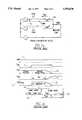
- FIG. 1ais a diagrammatic representation of a forced commutation according to the prior art.
- FIG. 1bis a diagrammatic representation of certain qualitative parameters pertinent to the forced commutation represented in FIG. 1a.
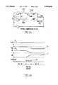
- FIG. 2ais a diagrammatic representation of a natural commutation according to the present invention.
- FIG. 2bis a diagrammatic representation of certain qualitative parameters pertinent to the natural commutation represented in FIG. 2a.
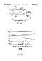
- FIG. 3ais a diagrammatic representation of a forced commutation according to the present invention.
- FIG. 3bis a diagrammatic representation of certain qualitative parameters pertinent to the forced commutation represented in FIG. 3a.
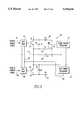
- FIG. 4is a diagrammatic representation of a basic matrix converter scheme for a three-phase power supply to an inductive load according to the present invention.
- FIG. 5is a schematic illustration of one embodiment of an AC polarity-controlled, bi-directional power switch according to the present invention.
- FIG. 6is a schematic illustration of one embodiment of a switch gating control circuit according to the present invention.
- the method and apparatus of the presently preferred embodimentsprovide unrestricted frequency conversion, high quality input and output waveforms, and a unity input displacement factor, and may be used at high switching frequencies and high power levels. Because about half of the commutations can be completely or partially natural, switching losses can be substantially reduced. Due to the use of an overlap gating period, and the elimination of systematic underlap gating intervals, the additional circuitry previously required to detect the recovery of each switch may be eliminated.
- FIG. 1aillustrates forced commutation with switch gating underlap found in the prior art, with FIG. 1b indicating the qualitative states of the parameters pertinent to the forced commutation illustrated in FIG. 1a.
- This forced commutation processis used to steer the output load current from a closed switch, SW1, to the next switch, SW2, in sequence within a group.
- switch SW1When switch SW1 is opened, the voltage, 11, across SW1 rapidly rises to a level defined by a voltage clamp.
- the load current, 10flows through the voltage clamp on SW1, an underlap period, 14, is allowed to expire before SW2 is gated ON.
- a commutation loop current, 12athen rises approximately linearly from zero to the load current as seen in trace 12 for the current through SW2.
- the underlap period, 14is partly intentional to account for imprecise detection of the recovery instant of SW1, and partly due to the turn-on delay of SW2.
- This commutation processcauses considerable energy to be absorbed, and load power lost, by the voltage clamp every time it occurs.
- the energy lost during this commutation processincludes a component 13a proportional to the length of underlap period 14, and another 13b related to the inductance of the commutation loop.
- the commutation method hereincan employ a simple switching control strategy that allows the converter to use natural, instead of forced, commutation whenever possible. Losses are further reduced through the elimination of systematic switching underlap intervals. However, selective underlap intervals may be imposed to prevent shorting of the AC mains where one switch is positively enabled and one switch is negatively enabled at the same time within the same group in the interval during which the polarity enable transition occurs.
- a switch group of an AC matrix convertercan be selected for either positive or negative current conduction.
- the decision to select for either positive or negative current conductioncan be made continuously. This decision can be facilitated when the matrix converter is operated under closed-loop current control, so that a desired reference current value is available for each switch group.
- an actual current-derived parameter measured from the matrix converter output circuitmay be used in addition to, or in place of, the closed-loop reference current value.
- FIG. 2aillustrates a natural commutation with switch gating overlap according to the present invention.
- FIG. 2billustrates the qualitative states of the parameters pertinent to the natural commutation illustrated in FIG. 2a.
- the polarity of the source voltage, 19,can be assumed to be negative, and the switch group in the figure is enabled for positive current conduction.
- the load current, 16flows through SW1 initially as seen in trace 16a for the current in SW1.
- the first action takenis to turn ON the next switch in the switching sequence, SW2, while SW1 is left ON.
- a commutation loop currentwill begin to flow and the load current 16 commutates in a natural way to SW2, as seen in tract 17 for the current in SW2, while current 16a in SW1 may be reduced to zero.
- the length of the overlap period 18is regulated such that natural commutation is possible, even likely, during overlap period 18. In the case shown in FIGS. 2a and 2b, the natural commutation is completed within the underlap period 18. However, if natural commutation has not concluded by the end of overlap period, 18, the first switch circuit is disabled and forced commutation of the load current to the second switch circuit is effected.
- FIG. 3aillustrates a forced commutation with switch gating overlap according to the present invention.
- the commutationis forced at the end of the overlap period since it cannot occur naturally.
- FIG. 3billustrates the qualitative states of the parameters pertinent to the forced commutation illustrated in FIG. 3a.
- the polarity of the source voltage, 20,can be assumed to be positive, and the switch group in the figure is enabled for positive current conduction.
- the load current, 21also flows through SW1 initially, as seen in trace 21a for the current through SW1.
- the first action takenis to turn ON the next switch in the switching sequence, SW2, while SW1 is left ON.
- SW2will simply block the source voltage, no current will flow through SW2, and all of load current, 21, will flow through SW1, as seen in trace 21a.
- SW1is turned OFF and a commutation loop current rises until the load current 21 is completely transferred to SW2, as seen in trace 22 for the current through SW2.
- the load currentwill either have been partially or completely transferred to SW2 (i.e., as in FIG. 2a) or be still flowing in SW1 (i.e., as in FIG. 3a).
- SW1is gated OFF, and any remaining current is force- commutated to SW2.
- approximately half of the switching actionswill be effected by completely or partially natural commutation. Where natural commutation occurs, the switching energy loss will be reduced. Also, when forced commutation occurs, the need for underlap period is eliminated because the oncoming switch is already ON when the outgoing switch is gated OFF.
- a basic matrix converter schemeis shown using nine polarity-controlled, bi-directional switches grouped in three groups, GPX, GPY, and GPZ.
- One group, GPXcan include polarity-controlled, bi-directional switches AX, BX, and CX, for input phases A, B, and C, and the common output phase, X, respectively.
- switches AY, BY, and CYconstitute the second group, GPY, for common output phase Y.
- Switches AZ, BZ and CZbelong to the third group, GPZ, and common output phase Z.
- the switches within each of groups GPX, GPY, and GPZthe magnitude and frequency of the power delivered to inductive source may be regulated.
- matrix converter controllerswhich provide such selective control of switch circuits may be found in U.S. Pat. Nos. 4,962,399 and 5,005,115.
- One factor which affects the topology and functionality of switching control circuitsis the design of the power switch in each of the power switches in the matrix converter circuit.
- Switches 41, 42may be connected together in anti-series, that is, the emitters of switches 41, 42 may be connected together.
- Switches 41, 42can be a suitable static power switch, such as, for example, BJT, IGBT, FET, MCT, and the like.
- Switch 41can be immediately controlled by positive current enable gate drive 43; switch 42 can be immediately controlled by negative current enable gate drive 44.
- gate drives 43, 44share a common ground 47 and may be regulated by positive current enable input 45 or negative current enable input 46, respectively, and can be powered by gate power regulator 56, via its output 48.
- switches 41, 42, gate drives 43, 44, inputs 45, 46, and regulator 56can form a polarity-controlled bi-directional power switch as required in the present invention.
- gate power regulator 56provides power for the gate drives 43 or 44 from the energy stored in the voltage clamping capacitor 49.
- the power for the gate drivescould be derived from an independent source.
- Diodes 54, 55can act to bar the flow of current with an undesired polarity.
- positive gate enable drive 43turns ON switch 41
- current with positive polaritymay bypass switch 42 by flowing through diode 55.
- current polaritybecomes negative
- current flowcan be stopped due to the reverse biasing of diode 55.
- negative gate enable drive 44turns ON switch 42
- current with negative polaritymay bypass switch 41 by flowing through diode 54.
- the polarity of the currentbecomes positive, thereby reverse biasing diode 54, current flow through diode 54 can be stopped.
- switch circuit 40With switch 41 ON, and switch 42 OFF, switch circuit 40 is enabled for positive current flow. Current flows from the current source into the collector, and out of the emitter, of switch 41, into the anode, and out of the cathode, of diode 55 and out of switch 40 into the load. No substantial current flows through switch 42 or diodes 50, 51, or 54. With switch 41 OFF, and switch 42 ON, switch circuit 40 is enabled for negative current flow. Current flows from the current source into the collector, and out of the emitter, of switch 42, into the anode, and out of the cathode, of diode 54 and out of switch 40 into the load. No substantial current flows through switch 41 or diodes 50, 51 or 55.
- Voltage clampingcan be provided by voltage clamping capacitor 49 which acts in concert with diodes 50, 51, clamping limiter resistor 52, clamp voltage regulator switch 53 and clamp voltage regulator 57.
- regulator 57senses that the voltage across capacitor 49 exceeds a predetermined upper threshold value, regulator 57 can initiate voltage clamping by closing switch 53, thereby permitting current to shunt through resistor 52, thereby dissipating the voltage built up across capacitor 49.
- regulator 57can cease voltage clamping by opening switch 53.
- matrix converter controller 60generates a group current demand reference signal 61 which is to be processed by switch gating control circuit 63 to control the operation of switching group 62a, 62b, 62c.
- the polarity of signal 61is sensed and used to determine the current polarity which is desired for the individual AC power switch circuits in group 62a, 62b, 62c for a particular switching sequence.
- Reference signal 61can be conditioned by comparator 64 to generate a polarity state control signal 65. It may also be desirable to determine the desired current polarity using other indicia in addition to, or in substitution for, signal 61 such as, for example, actual current polarity.
- Signal 65can be further conditioned by rising edge delay device 66 to provide a polarity enable control signal 67 to positive current enable gates 68a, 68b, 68c where the HIGH state of 67 corresponds to "ENABLED".
- Gates 68a, 68b, 68ccan supply a positive current enable input to individual switch circuits in group 62a, 62b, 62c.
- Signal 65can also be inverted and passed through rising edge delay device 71 to provide a complementary control signal 69 to negative current enable gates 74a, 74b, 74c where the HIGH state of 69 corresponds to "ENABLED".
- Gates 74a, 74b, 74ccan supply a negative current enable input to individual switch circuits in group 62a, 62b, 62c.
- the rising edge delay circuits 66 and 71provide a brief "dead time" when current polarity changes. During this dead time, neither positive nor negative conduction is enabled.
- the signals 67, 69can create mutually exclusive conduction states for gates 68a, 68b, 68c and 74a, 74b, 74c for a given polarity.
- the outputs of negative current enable gates 74a, 74b, 74ccan be disabled when the outputs of gates 68a, 68b, 68c are enabled, and vice versa.
- a small underlap periodmay be selectively added by edge delay devices 66, 71, to the commutation process by momentarily disabling current enable gates 68a, 68b, 68c, 74a, 74b, 74c, respectively, which, in turn, can disable all switches in group 62a, 62b, 62c.
- matrix converter controller 60can also provide gating control circuit 63 with switch selection control signals 72a, 72b, 72c for each of the AC power switch circuits in group 62a, 62b, 62c.
- Signals 72a, 72b, 72ccan be used to determine which power switch circuits within group 62a, 62b, 62c are enabled and operative at any moment according to some predetermined switch selection sequence.
- Each of signals 72a, 72b, 72cmay be conditioned by interposing edge delay devices 73a, 73b, 73c between controller 60 and current enable gates 68a, 68b, 68c, 74a, 74b, 74c.
- edge delay devices 73a, 73b, 73ceffect falling edge delays where the LOW state corresponds to a request to disable the associated switch.
- the time delay thus imposed by delay devices 73a, 73b, 73ccan serve as the switching overlap time, or time during which any two switches of group 62a, 62b, 62c are enabled simultaneously.
Landscapes
- Engineering & Computer Science (AREA)
- Power Engineering (AREA)
- Ac-Ac Conversion (AREA)
Abstract
Description
Claims (12)
Priority Applications (1)
| Application Number | Priority Date | Filing Date | Title |
|---|---|---|---|
| US08/267,730US5594636A (en) | 1994-06-29 | 1994-06-29 | Matrix converter circuit and commutating method |
Applications Claiming Priority (1)
| Application Number | Priority Date | Filing Date | Title |
|---|---|---|---|
| US08/267,730US5594636A (en) | 1994-06-29 | 1994-06-29 | Matrix converter circuit and commutating method |
Publications (1)
| Publication Number | Publication Date |
|---|---|
| US5594636Atrue US5594636A (en) | 1997-01-14 |
Family
ID=23019920
Family Applications (1)
| Application Number | Title | Priority Date | Filing Date |
|---|---|---|---|
| US08/267,730Expired - LifetimeUS5594636A (en) | 1994-06-29 | 1994-06-29 | Matrix converter circuit and commutating method |
Country Status (1)
| Country | Link |
|---|---|
| US (1) | US5594636A (en) |
Cited By (59)
| Publication number | Priority date | Publication date | Assignee | Title |
|---|---|---|---|---|
| US5793064A (en)* | 1996-09-24 | 1998-08-11 | Allen Bradley Company, Llc | Bidirectional lateral insulated gate bipolar transistor |
| US5852559A (en)* | 1996-09-24 | 1998-12-22 | Allen Bradley Company, Llc | Power application circuits utilizing bidirectional insulated gate bipolar transistor |
| US5949672A (en)* | 1996-09-27 | 1999-09-07 | Abb Patent Gmbh | Three-phase matrix converter and method for operation thereof |
| US6014323A (en)* | 1997-08-08 | 2000-01-11 | Robicon Corporation | Multiphase power converter |
| US6087738A (en)* | 1998-08-20 | 2000-07-11 | Robicon Corporation | Variable output three-phase transformer |
| US6262555B1 (en) | 1998-10-02 | 2001-07-17 | Robicon Corporation | Apparatus and method to generate braking torque in an AC drive |
| US6320767B1 (en)* | 1998-12-18 | 2001-11-20 | Kabushiki Kaisha Toshiba | Inverter apparatus |
| WO2001091279A1 (en)* | 2000-05-23 | 2001-11-29 | Vestas Wind Systems A/S | Variable speed wind turbine having a matrix converter |
| US6398779B1 (en) | 1998-10-23 | 2002-06-04 | Sherwood Services Ag | Vessel sealing system |
| US20020135234A1 (en)* | 2001-03-22 | 2002-09-26 | Chekhet Eduard Mikhaylovich | Method of commutation of current by bi-directional switches of matrix converters |
| EP1199794A3 (en)* | 2000-10-16 | 2002-11-06 | ALSTOM (Switzerland) Ltd | Method for operating a matrix converter and matrix converter for carrying out this method |
| WO2002043235A3 (en)* | 2000-11-22 | 2002-11-21 | Siemens Ag | Method for controlling a matrix converter |
| WO2002043234A3 (en)* | 2000-11-22 | 2003-01-16 | Siemens Ag | Method for controlling a matrix converter |
| US20030151259A1 (en)* | 2002-02-11 | 2003-08-14 | Lorenz Feddersen | Variable speed wind turbine having a passive grid side rectifier with scalar power control and dependent pitch control |
| WO2003026110A3 (en)* | 2001-09-19 | 2003-10-30 | Marcus Ziegler | Commutation method in matrix converters |
| WO2003090337A1 (en)* | 2002-04-15 | 2003-10-30 | The University Of Nottingham | Power converter |
| US6675304B1 (en)* | 1999-11-29 | 2004-01-06 | Intel Corporation | System for transitioning a processor from a higher to a lower activity state by switching in and out of an impedance on the voltage regulator |
| US20040015163A1 (en)* | 1998-10-23 | 2004-01-22 | Buysse Steven P. | Method and system for controlling output of RF medical generator |
| US20040078227A1 (en)* | 2002-05-15 | 2004-04-22 | Morris Tommy J. | System and method for handling medical information |
| US20040147918A1 (en)* | 2002-12-10 | 2004-07-29 | Keppel David S. | Variable output crest factor electrosurgical generator |
| US20040167508A1 (en)* | 2002-02-11 | 2004-08-26 | Robert Wham | Vessel sealing system |
| US6796981B2 (en) | 1999-09-30 | 2004-09-28 | Sherwood Services Ag | Vessel sealing system |
| US20040230189A1 (en)* | 2002-12-10 | 2004-11-18 | Keppel David S. | Circuit for controlling arc energy from an electrosurgical generator |
| US20040266995A1 (en)* | 2001-08-24 | 2004-12-30 | Academia Sinica | Fibrinogenolytic proteases with thrombolytic and antihypertensive activities from Taiwan habu: medical application and novel process of expression and production |
| US20050021020A1 (en)* | 2003-05-15 | 2005-01-27 | Blaha Derek M. | System for activating an electrosurgical instrument |
| US20050113818A1 (en)* | 2003-11-20 | 2005-05-26 | Sartor Joe D. | Connector systems for electrosurgical generator |
| US20050197659A1 (en)* | 2004-03-02 | 2005-09-08 | Bahney Timothy J. | Vessel sealing system using capacitive RF dielectric heating |
| US20050219874A1 (en)* | 2004-03-31 | 2005-10-06 | Alstom Technology Ltd | Method for improving the mode of operation of a matrix converter |
| US20050237774A1 (en)* | 2002-11-11 | 2005-10-27 | Alstom Technology Ltd. | Method for operating a matrix converter and matrix converter for implementing the method |
| US20050248969A1 (en)* | 2004-03-31 | 2005-11-10 | Alstom Technology Ltd. | Method for improving the operation of a matrix converter |
| US20060079872A1 (en)* | 2004-10-08 | 2006-04-13 | Eggleston Jeffrey L | Devices for detecting heating under a patient return electrode |
| US20060161148A1 (en)* | 2005-01-13 | 2006-07-20 | Robert Behnke | Circuit and method for controlling an electrosurgical generator using a full bridge topology |
| US20060214645A1 (en)* | 2003-07-05 | 2006-09-28 | Alstom Technology Ltd | Frequency converter for high-speed generators |
| US20070093801A1 (en)* | 2005-10-21 | 2007-04-26 | Robert Behnke | Circuit and method for reducing stored energy in an electrosurgical generator |
| US20070093800A1 (en)* | 2003-05-01 | 2007-04-26 | Sherwood Services Ag | Method and system for programming and controlling an electrosurgical generator system |
| US20070173802A1 (en)* | 2006-01-24 | 2007-07-26 | Keppel David S | Method and system for transmitting data across patient isolation barrier |
| US20070208339A1 (en)* | 2006-03-03 | 2007-09-06 | Sherwood Services Ag | System and method for controlling electrosurgical snares |
| US7300435B2 (en) | 2003-11-21 | 2007-11-27 | Sherwood Services Ag | Automatic control system for an electrosurgical generator |
| US7317998B2 (en) | 2004-03-31 | 2008-01-08 | Alstom Technology Ltd | Method for the calculation and the assessment of the frequency spectrum of a matrix converter |
| US20080055953A1 (en)* | 2005-03-31 | 2008-03-06 | Alstom Technology Ltd. | Matrix converter |
| US20080079400A1 (en)* | 2005-03-31 | 2008-04-03 | Alstom Technology Ltd | Generator with high phase order |
| US7364577B2 (en) | 2002-02-11 | 2008-04-29 | Sherwood Services Ag | Vessel sealing system |
| USRE40388E1 (en) | 1997-04-09 | 2008-06-17 | Covidien Ag | Electrosurgical generator with adaptive power control |
| US7396336B2 (en) | 2003-10-30 | 2008-07-08 | Sherwood Services Ag | Switched resonant ultrasonic power amplifier system |
| EP1976105A1 (en)* | 2007-03-30 | 2008-10-01 | ALSTOM Technology Ltd | Active generator control sequence |
| US7513896B2 (en) | 2006-01-24 | 2009-04-07 | Covidien Ag | Dual synchro-resonant electrosurgical apparatus with bi-directional magnetic coupling |
| US20090161398A1 (en)* | 2006-06-22 | 2009-06-25 | Alstom Technology Ltd | Method of controlling a three level converter |
| US20090265040A1 (en)* | 2008-04-21 | 2009-10-22 | Paluszek Michael A | Matrix Converters For Wind Energy Conversion Systems |
| US7628786B2 (en) | 2004-10-13 | 2009-12-08 | Covidien Ag | Universal foot switch contact port |
| US7749217B2 (en) | 2002-05-06 | 2010-07-06 | Covidien Ag | Method and system for optically detecting blood and controlling a generator during electrosurgery |
| US7766905B2 (en) | 2004-02-12 | 2010-08-03 | Covidien Ag | Method and system for continuity testing of medical electrodes |
| US7947039B2 (en) | 2005-12-12 | 2011-05-24 | Covidien Ag | Laparoscopic apparatus for performing electrosurgical procedures |
| US20110199032A1 (en)* | 2010-02-17 | 2011-08-18 | Kabushiki Kaisha Yaskawa Denki | Control apparatus for matrix converter |
| US8104956B2 (en) | 2003-10-23 | 2012-01-31 | Covidien Ag | Thermocouple measurement circuit |
| DE19746797B4 (en)* | 1997-10-23 | 2012-05-24 | Siemens Ag | Method for controlling bidirectional switches in power converters |
| US8808161B2 (en) | 2003-10-23 | 2014-08-19 | Covidien Ag | Redundant temperature monitoring in electrosurgical systems for safety mitigation |
| US20150085553A1 (en)* | 2013-09-26 | 2015-03-26 | Kabushiki Kaisha Yaskawa Denki | Matrix converter |
| US20160054751A1 (en)* | 2014-08-25 | 2016-02-25 | Kabushiki Kaisha Yaskawa Denki | Matrix converter, matrix converter control device and matrix converter control method |
| US10008920B2 (en) | 2015-03-25 | 2018-06-26 | Murata Manufacturing Co., Ltd. | Apparatus and method of fast commutation for matrix converter-based rectifier |
Citations (15)
| Publication number | Priority date | Publication date | Assignee | Title |
|---|---|---|---|---|
| US4642751A (en)* | 1986-02-14 | 1987-02-10 | Westinghouse Electric Corp. | Hidden DC-link AC/AC converter using bilateral power switches |
| US4648022A (en)* | 1986-02-14 | 1987-03-03 | Westinghouse Electric Corp. | Matrix converter control system |
| US4697131A (en)* | 1985-12-11 | 1987-09-29 | Westinghouse Electric Corp. | Voltage source inverter and variable frequency, constant voltage AC motor drive embodying the same |
| US4697230A (en)* | 1986-06-23 | 1987-09-29 | Westinghouse Electric Corp. | AC power supplied static switching apparatus having energy recovery capability |
| US4707651A (en)* | 1986-07-22 | 1987-11-17 | Westinghouse Electric Corp. | Voltage-controlled field-oriented induction motor control system |
| US4805082A (en)* | 1988-03-14 | 1989-02-14 | Westinghouse Electric Corp. | Regenerative two-quadrant converter |
| US4833588A (en)* | 1988-08-31 | 1989-05-23 | Westinghouse Electric Corp. | Direct AC/AC converter system |
| US4862054A (en)* | 1988-10-31 | 1989-08-29 | Westinghouse Electric Corp. | Tacho-less vector control adaptive system for motor drive |
| US4885518A (en)* | 1987-08-21 | 1989-12-05 | Westinghouse Electric Corp. | Induction motor torque/flux control system |
| US4959602A (en)* | 1989-06-02 | 1990-09-25 | Westinghouse Electric Corp. | Ac motor drive with improved voltage-source inverter |
| US4962339A (en)* | 1987-08-21 | 1990-10-09 | Westinghouse Electric Corp. | Pole-tying current control apparatus |
| US5005115A (en)* | 1989-07-28 | 1991-04-02 | Westinghouse Electric Corp. | Forced-commutated current-source converter and AC motor drive using the same |
| US5168204A (en)* | 1992-04-16 | 1992-12-01 | Westinghouse Electric Corp. | Automatic motor torque and flux controller for battery-powered vehicle drive |
| US5182508A (en)* | 1992-04-16 | 1993-01-26 | Westinghouse Electric Corp. | Reconfigurable AC induction motor drive for battery-powered vehicle |
| US5198746A (en)* | 1991-09-16 | 1993-03-30 | Westinghouse Electric Corp. | Transmission line dynamic impedance compensation system |
- 1994
- 1994-06-29USUS08/267,730patent/US5594636A/ennot_activeExpired - Lifetime
Patent Citations (15)
| Publication number | Priority date | Publication date | Assignee | Title |
|---|---|---|---|---|
| US4697131A (en)* | 1985-12-11 | 1987-09-29 | Westinghouse Electric Corp. | Voltage source inverter and variable frequency, constant voltage AC motor drive embodying the same |
| US4648022A (en)* | 1986-02-14 | 1987-03-03 | Westinghouse Electric Corp. | Matrix converter control system |
| US4642751A (en)* | 1986-02-14 | 1987-02-10 | Westinghouse Electric Corp. | Hidden DC-link AC/AC converter using bilateral power switches |
| US4697230A (en)* | 1986-06-23 | 1987-09-29 | Westinghouse Electric Corp. | AC power supplied static switching apparatus having energy recovery capability |
| US4707651A (en)* | 1986-07-22 | 1987-11-17 | Westinghouse Electric Corp. | Voltage-controlled field-oriented induction motor control system |
| US4885518A (en)* | 1987-08-21 | 1989-12-05 | Westinghouse Electric Corp. | Induction motor torque/flux control system |
| US4962339A (en)* | 1987-08-21 | 1990-10-09 | Westinghouse Electric Corp. | Pole-tying current control apparatus |
| US4805082A (en)* | 1988-03-14 | 1989-02-14 | Westinghouse Electric Corp. | Regenerative two-quadrant converter |
| US4833588A (en)* | 1988-08-31 | 1989-05-23 | Westinghouse Electric Corp. | Direct AC/AC converter system |
| US4862054A (en)* | 1988-10-31 | 1989-08-29 | Westinghouse Electric Corp. | Tacho-less vector control adaptive system for motor drive |
| US4959602A (en)* | 1989-06-02 | 1990-09-25 | Westinghouse Electric Corp. | Ac motor drive with improved voltage-source inverter |
| US5005115A (en)* | 1989-07-28 | 1991-04-02 | Westinghouse Electric Corp. | Forced-commutated current-source converter and AC motor drive using the same |
| US5198746A (en)* | 1991-09-16 | 1993-03-30 | Westinghouse Electric Corp. | Transmission line dynamic impedance compensation system |
| US5168204A (en)* | 1992-04-16 | 1992-12-01 | Westinghouse Electric Corp. | Automatic motor torque and flux controller for battery-powered vehicle drive |
| US5182508A (en)* | 1992-04-16 | 1993-01-26 | Westinghouse Electric Corp. | Reconfigurable AC induction motor drive for battery-powered vehicle |
Non-Patent Citations (2)
| Title |
|---|
| Charles L. Neft and Colin D. Schauder, "Theory and Design of a 30-hp Matrix Converter", IEEE Transactions of Industry Applications, vol. 28, No. 3, May/Jun. 1992. |
| Charles L. Neft and Colin D. Schauder, Theory and Design of a 30 hp Matrix Converter , IEEE Transactions of Industry Applications, vol. 28, No. 3, May/Jun. 1992.* |
Cited By (105)
| Publication number | Priority date | Publication date | Assignee | Title |
|---|---|---|---|---|
| US5852559A (en)* | 1996-09-24 | 1998-12-22 | Allen Bradley Company, Llc | Power application circuits utilizing bidirectional insulated gate bipolar transistor |
| US5793064A (en)* | 1996-09-24 | 1998-08-11 | Allen Bradley Company, Llc | Bidirectional lateral insulated gate bipolar transistor |
| US5949672A (en)* | 1996-09-27 | 1999-09-07 | Abb Patent Gmbh | Three-phase matrix converter and method for operation thereof |
| USRE40388E1 (en) | 1997-04-09 | 2008-06-17 | Covidien Ag | Electrosurgical generator with adaptive power control |
| US6014323A (en)* | 1997-08-08 | 2000-01-11 | Robicon Corporation | Multiphase power converter |
| DE19746797B4 (en)* | 1997-10-23 | 2012-05-24 | Siemens Ag | Method for controlling bidirectional switches in power converters |
| US6087738A (en)* | 1998-08-20 | 2000-07-11 | Robicon Corporation | Variable output three-phase transformer |
| US6417644B2 (en) | 1998-10-02 | 2002-07-09 | Robicon Corporation | Apparatus and method to generate braking torque in an AC drive |
| US6262555B1 (en) | 1998-10-02 | 2001-07-17 | Robicon Corporation | Apparatus and method to generate braking torque in an AC drive |
| US6398779B1 (en) | 1998-10-23 | 2002-06-04 | Sherwood Services Ag | Vessel sealing system |
| US7137980B2 (en) | 1998-10-23 | 2006-11-21 | Sherwood Services Ag | Method and system for controlling output of RF medical generator |
| US20050101951A1 (en)* | 1998-10-23 | 2005-05-12 | Robert Wham | Vessel sealing system |
| US20040015163A1 (en)* | 1998-10-23 | 2004-01-22 | Buysse Steven P. | Method and system for controlling output of RF medical generator |
| US7303557B2 (en) | 1998-10-23 | 2007-12-04 | Sherwood Services Ag | Vessel sealing system |
| US6320767B1 (en)* | 1998-12-18 | 2001-11-20 | Kabushiki Kaisha Toshiba | Inverter apparatus |
| US6796981B2 (en) | 1999-09-30 | 2004-09-28 | Sherwood Services Ag | Vessel sealing system |
| US6675304B1 (en)* | 1999-11-29 | 2004-01-06 | Intel Corporation | System for transitioning a processor from a higher to a lower activity state by switching in and out of an impedance on the voltage regulator |
| US6566764B2 (en)* | 2000-05-23 | 2003-05-20 | Vestas Wind Systems A/S, R&D | Variable speed wind turbine having a matrix converter |
| US20040026929A1 (en)* | 2000-05-23 | 2004-02-12 | Vestas Wind Systems A/S | Variable speed wind turbine having a matrix converter |
| US6856038B2 (en) | 2000-05-23 | 2005-02-15 | Vestas Wind Systems A/S | Variable speed wind turbine having a matrix converter |
| WO2001091279A1 (en)* | 2000-05-23 | 2001-11-29 | Vestas Wind Systems A/S | Variable speed wind turbine having a matrix converter |
| US6519170B2 (en) | 2000-10-16 | 2003-02-11 | Alstom (Switzerland) Ltd | Method for operating a matrix converter and matrix converter for implementing the method |
| EP1199794A3 (en)* | 2000-10-16 | 2002-11-06 | ALSTOM (Switzerland) Ltd | Method for operating a matrix converter and matrix converter for carrying out this method |
| US20040027843A1 (en)* | 2000-11-22 | 2004-02-12 | Siemens Aktiengesellschaft | Method for controlling a matrix converter |
| US6744650B2 (en) | 2000-11-22 | 2004-06-01 | Siemens Ag | Method for controlling a matrix converter |
| US6760239B2 (en) | 2000-11-22 | 2004-07-06 | Siemens Aktiengesellschaft | Method for controlling a matrix converter |
| WO2002043234A3 (en)* | 2000-11-22 | 2003-01-16 | Siemens Ag | Method for controlling a matrix converter |
| WO2002043235A3 (en)* | 2000-11-22 | 2002-11-21 | Siemens Ag | Method for controlling a matrix converter |
| US20030202369A1 (en)* | 2000-11-22 | 2003-10-30 | Siemens Aktiengesellschaft | Method for controlling a matrix converter |
| US20020135234A1 (en)* | 2001-03-22 | 2002-09-26 | Chekhet Eduard Mikhaylovich | Method of commutation of current by bi-directional switches of matrix converters |
| US6826065B2 (en)* | 2001-03-22 | 2004-11-30 | Eduard Mikhaylovich Chekhet | Method of commutation of current by bi-directional switches of matrix converters |
| US20040266995A1 (en)* | 2001-08-24 | 2004-12-30 | Academia Sinica | Fibrinogenolytic proteases with thrombolytic and antihypertensive activities from Taiwan habu: medical application and novel process of expression and production |
| WO2003026110A3 (en)* | 2001-09-19 | 2003-10-30 | Marcus Ziegler | Commutation method in matrix converters |
| US20040167508A1 (en)* | 2002-02-11 | 2004-08-26 | Robert Wham | Vessel sealing system |
| US7015595B2 (en) | 2002-02-11 | 2006-03-21 | Vestas Wind Systems A/S | Variable speed wind turbine having a passive grid side rectifier with scalar power control and dependent pitch control |
| US20030151259A1 (en)* | 2002-02-11 | 2003-08-14 | Lorenz Feddersen | Variable speed wind turbine having a passive grid side rectifier with scalar power control and dependent pitch control |
| US6856040B2 (en) | 2002-02-11 | 2005-02-15 | Vestas Wind Systems A/S | Variable speed wind turbine having a passive grid side rectifier with scalar power control and dependent pitch control |
| US20040217594A1 (en)* | 2002-02-11 | 2004-11-04 | Vestas Wind Systems A/S | Variable speed wind turbine having a passive grid side rectifier with scalar power control and dependent pitch control |
| US7364577B2 (en) | 2002-02-11 | 2008-04-29 | Sherwood Services Ag | Vessel sealing system |
| US6933625B2 (en) | 2002-02-11 | 2005-08-23 | Vestas Wind Systems A/S | Variable speed wind turbine having a passive grid side rectifier with scalar power control and dependent pitch control |
| US20050281066A1 (en)* | 2002-04-15 | 2005-12-22 | Patrick Wheeler | Power converter |
| WO2003090337A1 (en)* | 2002-04-15 | 2003-10-30 | The University Of Nottingham | Power converter |
| US7749217B2 (en) | 2002-05-06 | 2010-07-06 | Covidien Ag | Method and system for optically detecting blood and controlling a generator during electrosurgery |
| US20040078227A1 (en)* | 2002-05-15 | 2004-04-22 | Morris Tommy J. | System and method for handling medical information |
| US7084524B2 (en) | 2002-11-11 | 2006-08-01 | Alstom Technology Ltd. | Bi-directional matrix converter with reverse start-up |
| US20050237774A1 (en)* | 2002-11-11 | 2005-10-27 | Alstom Technology Ltd. | Method for operating a matrix converter and matrix converter for implementing the method |
| US20060178664A1 (en)* | 2002-12-10 | 2006-08-10 | Keppel David S | Circuit for controlling arc energy from an electrosurgical generator |
| US7044948B2 (en) | 2002-12-10 | 2006-05-16 | Sherwood Services Ag | Circuit for controlling arc energy from an electrosurgical generator |
| US20040147918A1 (en)* | 2002-12-10 | 2004-07-29 | Keppel David S. | Variable output crest factor electrosurgical generator |
| US7824400B2 (en) | 2002-12-10 | 2010-11-02 | Covidien Ag | Circuit for controlling arc energy from an electrosurgical generator |
| US20040230189A1 (en)* | 2002-12-10 | 2004-11-18 | Keppel David S. | Circuit for controlling arc energy from an electrosurgical generator |
| US7255694B2 (en) | 2002-12-10 | 2007-08-14 | Sherwood Services Ag | Variable output crest factor electrosurgical generator |
| US7722601B2 (en) | 2003-05-01 | 2010-05-25 | Covidien Ag | Method and system for programming and controlling an electrosurgical generator system |
| US8012150B2 (en) | 2003-05-01 | 2011-09-06 | Covidien Ag | Method and system for programming and controlling an electrosurgical generator system |
| US20070093800A1 (en)* | 2003-05-01 | 2007-04-26 | Sherwood Services Ag | Method and system for programming and controlling an electrosurgical generator system |
| US20050021020A1 (en)* | 2003-05-15 | 2005-01-27 | Blaha Derek M. | System for activating an electrosurgical instrument |
| US20060214645A1 (en)* | 2003-07-05 | 2006-09-28 | Alstom Technology Ltd | Frequency converter for high-speed generators |
| US7180270B2 (en) | 2003-07-05 | 2007-02-20 | Alstom Technology Ltd. | Frequency converter for high-speed generators |
| US8104956B2 (en) | 2003-10-23 | 2012-01-31 | Covidien Ag | Thermocouple measurement circuit |
| US8808161B2 (en) | 2003-10-23 | 2014-08-19 | Covidien Ag | Redundant temperature monitoring in electrosurgical systems for safety mitigation |
| US9768373B2 (en) | 2003-10-30 | 2017-09-19 | Covidien Ag | Switched resonant ultrasonic power amplifier system |
| US7396336B2 (en) | 2003-10-30 | 2008-07-08 | Sherwood Services Ag | Switched resonant ultrasonic power amplifier system |
| US7131860B2 (en) | 2003-11-20 | 2006-11-07 | Sherwood Services Ag | Connector systems for electrosurgical generator |
| US20050113818A1 (en)* | 2003-11-20 | 2005-05-26 | Sartor Joe D. | Connector systems for electrosurgical generator |
| US20080248685A1 (en)* | 2003-11-20 | 2008-10-09 | Joe Don Sartor | Connector Systems for Electrosurgical Generator |
| US7766693B2 (en) | 2003-11-20 | 2010-08-03 | Covidien Ag | Connector systems for electrosurgical generator |
| US7300435B2 (en) | 2003-11-21 | 2007-11-27 | Sherwood Services Ag | Automatic control system for an electrosurgical generator |
| US7766905B2 (en) | 2004-02-12 | 2010-08-03 | Covidien Ag | Method and system for continuity testing of medical electrodes |
| US20050197659A1 (en)* | 2004-03-02 | 2005-09-08 | Bahney Timothy J. | Vessel sealing system using capacitive RF dielectric heating |
| US7780662B2 (en) | 2004-03-02 | 2010-08-24 | Covidien Ag | Vessel sealing system using capacitive RF dielectric heating |
| US20050248969A1 (en)* | 2004-03-31 | 2005-11-10 | Alstom Technology Ltd. | Method for improving the operation of a matrix converter |
| US7321835B2 (en) | 2004-03-31 | 2008-01-22 | Alstom Technology Ltd | Method for improving the mode of operation of a matrix converter |
| US7466574B2 (en) | 2004-03-31 | 2008-12-16 | Alstom Technology Ltd | Method for improving the operation of a matrix converter |
| US20050219874A1 (en)* | 2004-03-31 | 2005-10-06 | Alstom Technology Ltd | Method for improving the mode of operation of a matrix converter |
| US7317998B2 (en) | 2004-03-31 | 2008-01-08 | Alstom Technology Ltd | Method for the calculation and the assessment of the frequency spectrum of a matrix converter |
| US20060079872A1 (en)* | 2004-10-08 | 2006-04-13 | Eggleston Jeffrey L | Devices for detecting heating under a patient return electrode |
| US7628786B2 (en) | 2004-10-13 | 2009-12-08 | Covidien Ag | Universal foot switch contact port |
| US20060161148A1 (en)* | 2005-01-13 | 2006-07-20 | Robert Behnke | Circuit and method for controlling an electrosurgical generator using a full bridge topology |
| US9106168B2 (en) | 2005-03-31 | 2015-08-11 | Alstom Technology Ltd. | Method for re-powering a star-connected stator |
| US20080055953A1 (en)* | 2005-03-31 | 2008-03-06 | Alstom Technology Ltd. | Matrix converter |
| RU2366062C2 (en)* | 2005-03-31 | 2009-08-27 | Альстом Текнолоджи Лтд | Generator with high phase order |
| US20080079400A1 (en)* | 2005-03-31 | 2008-04-03 | Alstom Technology Ltd | Generator with high phase order |
| US7928623B2 (en) | 2005-03-31 | 2011-04-19 | Alstom Technology Ltd | Generator with high phase order |
| US7460377B2 (en) | 2005-03-31 | 2008-12-02 | Alstom Technology Ltd | Matrix converter |
| US9522032B2 (en) | 2005-10-21 | 2016-12-20 | Covidien Ag | Circuit and method for reducing stored energy in an electrosurgical generator |
| US8734438B2 (en) | 2005-10-21 | 2014-05-27 | Covidien Ag | Circuit and method for reducing stored energy in an electrosurgical generator |
| US20070093801A1 (en)* | 2005-10-21 | 2007-04-26 | Robert Behnke | Circuit and method for reducing stored energy in an electrosurgical generator |
| US7947039B2 (en) | 2005-12-12 | 2011-05-24 | Covidien Ag | Laparoscopic apparatus for performing electrosurgical procedures |
| US20070173802A1 (en)* | 2006-01-24 | 2007-07-26 | Keppel David S | Method and system for transmitting data across patient isolation barrier |
| US7513896B2 (en) | 2006-01-24 | 2009-04-07 | Covidien Ag | Dual synchro-resonant electrosurgical apparatus with bi-directional magnetic coupling |
| US7651493B2 (en) | 2006-03-03 | 2010-01-26 | Covidien Ag | System and method for controlling electrosurgical snares |
| US20070208339A1 (en)* | 2006-03-03 | 2007-09-06 | Sherwood Services Ag | System and method for controlling electrosurgical snares |
| US20090161398A1 (en)* | 2006-06-22 | 2009-06-25 | Alstom Technology Ltd | Method of controlling a three level converter |
| US7800926B2 (en) | 2006-06-22 | 2010-09-21 | Alstom Technology Ltd | Method of controlling a three level converter |
| US8045354B2 (en) | 2007-03-30 | 2011-10-25 | Alstom Technology Ltd | Active generator control sequence |
| US20080247211A1 (en)* | 2007-03-30 | 2008-10-09 | Alstom Technology Ltd | Active generator control sequence |
| EP1976105A1 (en)* | 2007-03-30 | 2008-10-01 | ALSTOM Technology Ltd | Active generator control sequence |
| US8311679B2 (en) | 2008-04-21 | 2012-11-13 | Paluszek Michael A | Matrix converters for wind energy conversion systems |
| US20090265040A1 (en)* | 2008-04-21 | 2009-10-22 | Paluszek Michael A | Matrix Converters For Wind Energy Conversion Systems |
| US8350518B2 (en)* | 2010-02-17 | 2013-01-08 | Kabushiki Kaisha Yaskawa Denki | Control apparatus for matrix converter |
| US20110199032A1 (en)* | 2010-02-17 | 2011-08-18 | Kabushiki Kaisha Yaskawa Denki | Control apparatus for matrix converter |
| US20150085553A1 (en)* | 2013-09-26 | 2015-03-26 | Kabushiki Kaisha Yaskawa Denki | Matrix converter |
| US9473037B2 (en)* | 2013-09-26 | 2016-10-18 | Kabushiki Kaisha Yaskawa Denki | Matrix converter |
| US20160054751A1 (en)* | 2014-08-25 | 2016-02-25 | Kabushiki Kaisha Yaskawa Denki | Matrix converter, matrix converter control device and matrix converter control method |
| US10008920B2 (en) | 2015-03-25 | 2018-06-26 | Murata Manufacturing Co., Ltd. | Apparatus and method of fast commutation for matrix converter-based rectifier |
Similar Documents
| Publication | Publication Date | Title |
|---|---|---|
| US5594636A (en) | Matrix converter circuit and commutating method | |
| Empringham et al. | Intelligent commutation of matrix converter bi-directional switch cells using novel gate drive techniques | |
| US4670828A (en) | Bi-directional switch for neutral point clamped PWM inverter | |
| US4697131A (en) | Voltage source inverter and variable frequency, constant voltage AC motor drive embodying the same | |
| US6603647B2 (en) | Method for controlling freewheeling paths in a matrix converter | |
| US4757435A (en) | Static-controlled current-source AC/DC power converter and DC/AC power converter, and protection system embodying the same | |
| JPH01274666A (en) | AC-DC converter device | |
| US4571551A (en) | Flyback modulated switching power amplifier | |
| US4720776A (en) | DC bus shorting apparatus and method for polyphase AC inverter | |
| US4511956A (en) | Power inverter using separate starting inverter | |
| JP3479899B2 (en) | Voltage regulator | |
| US4970635A (en) | Inverter with proportional base drive controlled by a current transformer | |
| US5057987A (en) | Fault detection and protection strategy for a pair of complementary GTO thyristors | |
| EP0325301B1 (en) | Power control apparatus | |
| EP1306964A1 (en) | Control method for an AC-AC matrix converter | |
| KR910000102B1 (en) | Frequency converter for stabilized power supply of asynchronous motor | |
| CA2287798C (en) | Static voltage regulator | |
| US4247887A (en) | AC--AC Converter device | |
| Sikorski et al. | Quasi-resonant parallel DC link circuit for high-frequency DC-AC inverters | |
| JPH1023754A (en) | Dc power supply apparatus | |
| WO1993006652A1 (en) | Minimization of gto gate driver losses when antiparallel diode conduct | |
| JP2000312480A (en) | Current inverter | |
| JP3103705B2 (en) | Lighting equipment | |
| Dawson et al. | A fast dc current breaker | |
| JPH04174999A (en) | arc power circuit |
Legal Events
| Date | Code | Title | Description |
|---|---|---|---|
| AS | Assignment | Owner name:WESTINGHOUSE ELECTRIC CORPORATION, PENNSYLVANIA Free format text:ASSIGNMENT OF ASSIGNORS INTEREST;ASSIGNOR:SCHAUDER, COLIN D.;REEL/FRAME:007068/0094 Effective date:19940531 | |
| AS | Assignment | Owner name:NORTHROP GRUMMAN CORPORATION, CALIFORNIA Free format text:ASSIGNMENT OF ASSIGNORS INTEREST;ASSIGNOR:WESTINGHOUSE ELECTRIC CORPORATION;REEL/FRAME:008104/0190 Effective date:19960301 | |
| STCF | Information on status: patent grant | Free format text:PATENTED CASE | |
| FEPP | Fee payment procedure | Free format text:PAYOR NUMBER ASSIGNED (ORIGINAL EVENT CODE: ASPN); ENTITY STATUS OF PATENT OWNER: SMALL ENTITY | |
| FPAY | Fee payment | Year of fee payment:4 | |
| FEPP | Fee payment procedure | Free format text:PAT HOLDER CLAIMS SMALL ENTITY STATUS, ENTITY STATUS SET TO SMALL (ORIGINAL EVENT CODE: LTOS); ENTITY STATUS OF PATENT OWNER: SMALL ENTITY | |
| REFU | Refund | Free format text:REFUND - 7.5 YR SURCHARGE - LATE PMT W/IN 6 MO, LARGE ENTITY (ORIGINAL EVENT CODE: R1555); ENTITY STATUS OF PATENT OWNER: SMALL ENTITY Free format text:REFUND - PAYMENT OF MAINTENANCE FEE, 8TH YEAR, LARGE ENTITY (ORIGINAL EVENT CODE: R1552); ENTITY STATUS OF PATENT OWNER: SMALL ENTITY | |
| REMI | Maintenance fee reminder mailed | ||
| FPAY | Fee payment | Year of fee payment:8 | |
| SULP | Surcharge for late payment | Year of fee payment:7 | |
| REMI | Maintenance fee reminder mailed | ||
| FPAY | Fee payment | Year of fee payment:12 | |
| SULP | Surcharge for late payment | Year of fee payment:11 | |
| AS | Assignment | Owner name:SILICON VALLEY BANK, MASSACHUSETTS Free format text:AMENDED AND RESTATED INTELLECTUAL PROPERTY SECURITY AGREEMENT;ASSIGNORS:SATCON TECHNOLOGY CORPORATION;SATCON POWER SYSTEMS, INC.;SATCON ELECTRONICS, INC.;AND OTHERS;REEL/FRAME:026196/0547 Effective date:20110421 | |
| AS | Assignment | Owner name:SATCON TECHNOLOGY CORPORATION, MASSACHUSETTS Free format text:RELEASE BY SECURED PARTY;ASSIGNOR:SILICON VALLEY BANK;REEL/FRAME:031515/0595 Effective date:20130805 Owner name:PERFECT GALAXY INTERNATIONAL LIMITED, HONG KONG Free format text:RELEASE BY SECURED PARTY;ASSIGNOR:SILICON VALLEY BANK;REEL/FRAME:031515/0595 Effective date:20130805 Owner name:SATCON POWER SYSTEMS CANADA LTD., MASSACHUSETTS Free format text:RELEASE BY SECURED PARTY;ASSIGNOR:SILICON VALLEY BANK;REEL/FRAME:031515/0595 Effective date:20130805 Owner name:SATCON ELECTRONICS, INC., MASSACHUSETTS Free format text:RELEASE BY SECURED PARTY;ASSIGNOR:SILICON VALLEY BANK;REEL/FRAME:031515/0595 Effective date:20130805 Owner name:SATCON POWER SYSTEMS, INC., MASSACHUSETTS Free format text:RELEASE BY SECURED PARTY;ASSIGNOR:SILICON VALLEY BANK;REEL/FRAME:031515/0595 Effective date:20130805 | |
| AS | Assignment | Owner name:PERFECT GALAXY INTERNATIONAL LIMITED, HONG KONG Free format text:ASSIGNMENT OF ASSIGNORS INTEREST;ASSIGNOR:SATCON TECHNOLOGY CORPORATION;REEL/FRAME:031638/0454 Effective date:20130805 |