US5593649A - Canister with plasma gas mixture for sterilizer - Google Patents
Canister with plasma gas mixture for sterilizerDownload PDFInfo
- Publication number
- US5593649A US5593649AUS08/462,982US46298295AUS5593649AUS 5593649 AUS5593649 AUS 5593649AUS 46298295 AUS46298295 AUS 46298295AUS 5593649 AUS5593649 AUS 5593649A
- Authority
- US
- United States
- Prior art keywords
- plasma
- gas
- gas mixture
- sterilizing
- tube
- Prior art date
- Legal status (The legal status is an assumption and is not a legal conclusion. Google has not performed a legal analysis and makes no representation as to the accuracy of the status listed.)
- Expired - Lifetime
Links
Images


Classifications
- A—HUMAN NECESSITIES
- A61—MEDICAL OR VETERINARY SCIENCE; HYGIENE
- A61L—METHODS OR APPARATUS FOR STERILISING MATERIALS OR OBJECTS IN GENERAL; DISINFECTION, STERILISATION OR DEODORISATION OF AIR; CHEMICAL ASPECTS OF BANDAGES, DRESSINGS, ABSORBENT PADS OR SURGICAL ARTICLES; MATERIALS FOR BANDAGES, DRESSINGS, ABSORBENT PADS OR SURGICAL ARTICLES
- A61L2/00—Methods or apparatus for disinfecting or sterilising materials or objects other than foodstuffs or contact lenses; Accessories therefor
- A61L2/02—Methods or apparatus for disinfecting or sterilising materials or objects other than foodstuffs or contact lenses; Accessories therefor using physical phenomena
- A61L2/14—Plasma, i.e. ionised gases
- H—ELECTRICITY
- H05—ELECTRIC TECHNIQUES NOT OTHERWISE PROVIDED FOR
- H05H—PLASMA TECHNIQUE; PRODUCTION OF ACCELERATED ELECTRICALLY-CHARGED PARTICLES OR OF NEUTRONS; PRODUCTION OR ACCELERATION OF NEUTRAL MOLECULAR OR ATOMIC BEAMS
- H05H1/00—Generating plasma; Handling plasma
- H05H1/24—Generating plasma
- H05H1/46—Generating plasma using applied electromagnetic fields, e.g. high frequency or microwave energy
- Y—GENERAL TAGGING OF NEW TECHNOLOGICAL DEVELOPMENTS; GENERAL TAGGING OF CROSS-SECTIONAL TECHNOLOGIES SPANNING OVER SEVERAL SECTIONS OF THE IPC; TECHNICAL SUBJECTS COVERED BY FORMER USPC CROSS-REFERENCE ART COLLECTIONS [XRACs] AND DIGESTS
- Y10—TECHNICAL SUBJECTS COVERED BY FORMER USPC
- Y10S—TECHNICAL SUBJECTS COVERED BY FORMER USPC CROSS-REFERENCE ART COLLECTIONS [XRACs] AND DIGESTS
- Y10S422/00—Chemical apparatus and process disinfecting, deodorizing, preserving, or sterilizing
- Y10S422/906—Plasma or ion generation means
Definitions
- This inventionrelates to sterilization of articles with gaseous species.
- this inventionrelates to a canister containing a gas mixture, which mixture is adapted for use to sterilize articles with a neutral active species of a gas plasma generated from the gas mixture.
- a sterilizing methodmust effectively render all microbial organisms non-viable without damage to the article or goods being sterilized and its packaging.
- many disinfecting gases which meet this criteriasuch as ethylene oxide and irradiation methods, have been recognized to expose workers and the environment to safety hazards.
- Recent legislationhas been severely restricting the amount of hazardous gases such as ethylene oxide (a suspected carcinogen) in the working environment, or the use of any system or method which produces toxic residues or exhaust products. This has been presenting a major crisis in hospitals and other areas of the health industry.
- Plasmais an ionized body of gas which may be generated by the application of power from different sources. The ionized gas will contact microorganisms on the surfaces of the items to be sterilized and effectively destroy the microorganisms.
- Sterilizing plasmashave been generated with a wide variety of gases: argon, helium, or xenon (U.S. Pat. No. 3,851,436); argon, nitrogen, oxygen, helium, or xenon (U.S. Pat. No. 3,948,601); glutaraldehyde (U.S. Pat. No. 4,207,286); oxygen (U.S. Pat. No. 4,321,232); oxygen, nitrogen, helium, argon, or freon with pulsed pressure (U.S. Pat. No. 4,348,357); hydrogen peroxide (U.S. Pat. No.
- Non-plasma gas sterilization procedureshave been described using ozone (U.S. Pat. No. 3,704,096) and hydrogen peroxide (U.S. Pat. No. 4,169,123, 4,169,124, 4,230,663, 4,366,125, 4,289,728, 4,437,567, and 4,643,876). These materials have certain process actions which limit their sterilization applications and in some applications are toxic and leave undesirable residues.
- Plasma gas sterilizer systems described in U.S. Pat. Nos. 3,851,436 and 3,948,601comprise a plasma RF generation chamber.
- a gas plasma produced in the chamber with argon, helium, nitrogen, oxygen, or xenonis passed into a separate sterilization vacuum chamber.
- U.S. Pat. No. 4,643,876describes a hydrogen peroxide plasma RF generation chamber which also functions as the sterilizing chamber. Matching networks are required with the RF systems to adjust to the conductivity variations in the plasma generating zone.
- a canisterthat is adapted for use in a plasma induced sterilization process.
- the canistercontains a gas mixture that is pressurized to between about 2200 psig to about 2500 psig.
- the gas mixturehas about 2.0 to 2.4 (v/v) percent hydrogen and about 2.6 to 3.0 (v/v) percent oxygen, and the rest of the gas mixture is noble gas or a mixture of noble gases.
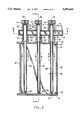
- FIG. 1is a top view of a plasma sterilizer of this invention.
- FIG. 2is a front view of the plasma sterilizer embodiment of FIG. 1.
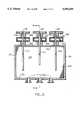
- FIG. 3is a cross-sectional view of the plasma sterilizer embodiment of FIG. 1 and FIG. 2, taken along the line 3--3 in FIG. 2.
- FIG. 4is a cross-sectional view of the plasma sterilizer embodiment of FIG. 3, taken along the line 4--4.
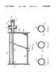
- FIG. 5is a cross-sectional view of tube 54 taken along line 5--5 in FIG. 3.
- FIG. 6is a cross-sectional view of tube 58 taken along line 6--6 in FIG. 3.
- FIG. 7is a cross-sectional view of tube 56 taken along line 7--7 in FIG. 3.
- FIG. 8is a partial cross-sectional view of the plasma generator tube and assembly of the embodiment of FIG. 1.
- FIG. 9is a partial, fragmentary, cross-sectional detail view of the plasma generator tube of the plasma generator shown in FIG. 8.
- FIG. 10is a cross-sectional view of the waveguide of the embodiment of FIG. 1, taken along the line 10--10 in FIG. 3.
- FIG. 11is a side cross-sectional view of an alternate single waveguide embodiment of the plasma sterilizer of this invention.
- FIG. 12is a cross-sectional view of the waveguide of the embodiment of FIG. 11, taken along the line 12--12.
- FIG. 13is a side cross-sectional view of a multiple magnetron embodiment of this invention.
- FIG. 14is a front cross-sectional view of the multiple waveguide embodiment of the plasma sterilizer of this invention, taken along the line 14--14 of FIG. 13.
- FIG. 15is a partial cross-sectional view of the plasma generator tube and assembly of the embodiment of FIG. 13.
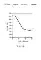
- FIG. 16graphically illustrates a typical survivor curve when practicing the invention using a plasma generated from a gas mixture according to the invention.
- a biological indicatorhere Bacillus circulans
- FIG. 17is a side sectional view of the plasma sterilizer according to another embodiment of the invention.
- FIG. 18is a detailed, sectional view of the plasma generator as a component of the plasma sterilizer shown in FIG. 17.
- ethylene oxide gas sterilizationhas made possible the sterilization of packaged articles, drugs, and medical supplies, and hospital systems are highly dependent upon these procedures.
- ethylene oxideis now suspected to be a dangerous carcinogen and a number of new state laws protecting worker safety and the environment are restricting further use of ethylene oxide sterilizers in hospital environments.
- ethylene oxideis known to be a dangerous material from several other aspects. In its pure form it is explosive and flammable and therefore requires that all equipment must be so designed as to be classified as non-explosive.
- the most popular form of the diluted or non-explosive mixturescontains fluorocarbons (Freon), which are no longer environmentally acceptable.
- fluorocarbonsFluorocarbons
- the gas sterilizer of this inventionproduces a plasma from a gas mixture containing a noble gas, such as argon or helium, together with a nonflammable mixture of oxygen and hydrogen.
- a noble gassuch as argon or helium
- This mixturecan be designated as non-flammable due to the concentration of flammable or combustion supportive gases being below defined levels of flammability, as evidenced in industry accepted standards published by the Bureau of Mines. Reference Bureau of Mines Bulletin 503, "Limits of Flammability of Gases and Vapors" and Bulletin 627, "Flammability Characteristics of Combustible Gases and Vapors". According to Lewis et al., Combustion Flame and Explosions of Gases, Academic Press (1951), the lower limit of flammability of hydrogen in air is 4.00%(v/v).
- the plasmais produced as a result of an applied electric or electromagnetic field, including any accompanying radiation which might be produced.
- the electromagnetic fieldcan cover a broad frequency range, and can be produced by a magnetron, klystron, or RF coil.
- a magnetronfor purposes of clarity of presentation and not by way of limitation, the description hereinafter describes the use of a magnetron as the electromagnetic field source, and the use of all other suitable sources of the electromagnetic field required for plasma production are intended to be included in this invention, including without limitation, magnetrons, klystron tubes, RF coils, and the like.
- the term "sterilization”connotes a process by which all viable forms of microorganisms are destroyed or removed from an object. Since microorganisms die according to first order chemical kinetics, it is customary to define sterility in terms of "probability of survivors.” The practical goal of a sterilization process is therefore measured as a probability (e.g., 10 -3 , 10 -6 , 10 -12 ), the probability indicating the lethal effect of a particular sterilizing dose or regimen. It is usual to assume increased time of exposure to a set of sterilizing conditions will decrease the probability of survivors accordingly. Doubling the sterilizing time of identical conditions would result in a doubling of the exponent of the probability term, for example 10 -6 would become 10 -12 .
- a probabilitye.g. 10 -3 , 10 -6 , 10 -12
- a plasma generator and a sterilizing chamberare used with the canister gas mixture.
- the canisterprovides a source of pressurized gas mixture in fluid communication with the plasma generator.
- U.S. Pat. No. 5,244,629issued Sep. 14, 1993, the disclosure of which is incorporated by reference, describes a pulsed treatment with one or more pulsed-vacuum cycles where one cycle involves exposing the article to be sterilized to a neutral active species of a gas plasma.
- This gas plasmamay be generated from the inventive gas mixture as is hereinafter further described and exemplified.
- Typical initial pressuresare in the range of about 2200 to about 2500 psig.
- the cylinderis replaced when the pressure drops to about 50 to 100 psig (about 350-700 kPa).
- the premixed gas mixturecan be stored under pressure in a standard gas cylinder equipped with a valve and a connecting fitting as specified by the Compressed Gas Association.
- the cylinder pressurecan be reduced and regulated by using a standard, conventional gas regulator, which may be mounted to the gas cylinder by a mating CGA fitting.
- the gaswill then flow during practice of the sterilizing method at the desired rate from the regulator to the sterilizer through conventional tubing connected with conventional gas tight fittings.
- the preferred gas concentrations of the premixed gases in the gas mixtureavoid the potential problem of flammability otherwise possible with an oxygen/hydrogen gas mixture in a noble gas carrier. Nevertheless, although these preferred concentrations are relatively low, the mixture is still useful as the source gas for a plasma formed species having sporicidal activity, as will be exemplified hereinafter.
- the optimum gas mixtureis about 2.2 ⁇ 0.2 (v/v) percent hydrogen, about 2.8 ⁇ 0.2 (v/v) percent oxygen, and the balance argon or helium, with this mixture being provided from a single container, such as a single pressurized gas canister.
- Other noble gasescould be used (neon, xenon, krypton), but they are less preferred due to expense.
- the present inventionrepresents a simpler apparatus since it eliminates such multiple regulating and sensing components required for feed lines from different gas cylinders. Consequently, overall operating performance and reliability are enhanced by eliminating the possibility of incorrect mixture proportions that could result from component failures or operator error. Additionally, routine operating costs are reduced and maintenance simplified.
- Such a premixed gas composition of the inventionmay be fed by inlet line 26.
- the operation of the control valves in valve complex 22is controlled by the central processing unit (CPU) 28 by standard algorithms or logic code or operating software.
- the control valves and CPUcan be any of the conventional, standard devices used for gas flow control in plasma generating equipment.
- the sterilizing chamber 4may comprise top plate 30, side plates 32 and 34, bottom plate 36, back plate 37, and front sealing door 38 through which articles or materials to be sterilized are placed in the chamber.
- the platesare shown attached together in a sealed relationship to form a vacuum chamber, such as by welding.
- the door 38is secured in a sealed relationship with the sterilizing chamber. It is attached to the chamber in a practical manner such as tracts or hinges at the top, side, or bottom with, in the case of apparatus shown, conventional hinge pins (structure not shown) to swing against abutting surfaces and an O-ring seal 40 (FIG. 3) of the side, top, and bottom plates, where the pressure difference between the internal chamber vacuum pressure and the surrounding atmospheric pressure holds it tightly in place.
- the doorcould also be constructed to slide open and to be closed.
- the plates and doorcan be made of any material having the strength required to withstand the external atmospheric pressure when the chamber is evacuated. Stainless steel or aluminum plates and door can be used.
- the internal surface material of the chamberis critical and greatly affects the number of killing species available in the chamber.
- One useful materialis pure (98%) aluminum which can be applied either as a liner or as a flame-sprayed coating on all internal walls of the stainless steel chamber.
- An alternate materialis nickel.
- the gasesare exhausted from the sterilizing chamber through exhaust outlet port 42 to a conventional vacuum pump system (not shown).
- FIG. 3is a top cross-sectional view of the plasma sterilizer embodiment of FIG. 1 and FIG. 2, taken along the line 3--3 in FIG. 2.
- FIG. 4is a side cross-sectional view of the plasma sterilizer embodiment of FIG. 1 and FIG. 3, taken along the line 4--4 in FIG. 3.
- Each of the plasma generators 10, 12, and 14comprise an inlet cap 44 with a gas inlet port 48 leading to a respective gas generator tube 51, 52, or 53 leading through the waveguide 8.
- the gasesare energized and convert in tubes 51, 52, and 53 to a plasma.
- the gas generator tubedirects the plasma flow into the gas distribution tubes 54, 56, and 58 from which the plasma is fed into the sterilizing chamber 60.
- the gas generator tubesare enclosed in tubular metal cooling tubes 62 and 64.
- the caps 44 and the cooling tubes 62 and 64are preferably provided with groves or cooling fins (not shown) in a conventional manner to increase their efficiency in removing heat from gas generator tubes.
- the distal ends of the gas distribution tubes 54, 56, and 58are supported by spring-biased end supports 66 mounted on sideplate 32, but could be modified for gas distributor plenum designs, as known in the art.
- the door 38is held in sealing engagement by atmospheric pressure against the O-ring seal 40 mounted in the flange 41 extending from the side plates 32 and 34, and the top and bottom plates 30 and 36 (not shown).
- additional conventional closure clamp or latch devicescan be used to insure closure of the door before chamber evacuation is initiated.
- FIG. 5, FIG. 6, and FIG. 7are cross-sectional views of gas distribution tubes 54, 58, and 56, respectively, showing angular positions of the gas distribution outlet ports.
- the outlet portsare positioned to provide plasma flow to all lower portions of the sterilizing chamber 60 where articles to be sterilized are placed.
- Tube 54 shown in FIG. 5is placed adjacent back plate 37 and directs plasma gases downward and toward the lower center of the chamber through outlet ports 70 and 72, respectively.
- Tube 58 shown in FIG. 6is placed adjacent the door 38 and directs plasma gases downward and toward the lower center of the chamber through outlet ports 74 and 76, respectively.
- Tube 56 shown in FIG. 7is placed in the central portion of the chamber 60 and directs plasma gases laterally downward through outlet ports 78 and 80.
- each tubecan have more than one angular set of outlet ports, each having different angles, along the length of the tube, as desired.
- the choice of outlet port angles and locationsshould be selected in view of how the articles to be sterilized are to be placed in the chamber and the type of article to be sterilized.
- the plasmais preferably directed through a change of direction before discharging it into the sterilizing chamber.
- the flow of plasmathus impinges on internal surfaces of the gas distribution and sterilizing chamber, thereby cooling it and evenly distributing it. This also prevents direct impingement of hot plasma onto the articles being sterilized, which greatly reduces the oxidation of sensitive packaging materials by the activated oxygen atoms in the plasma.
- FIG. 8is a partial top cross-sectional detail fragmentary view of plasma generator tube 12 of FIG. 3, and FIG. 9 is a more detailed view of the plasma generator tube outlet assembly shown in FIG. 3.
- the gas fed to the inlet port 48flows in the passageway 86.
- the gas mixturepasses into the proximal end of the tube 52 and through the excitation zone 87 within the waveguide 8 where the plasma is formed.
- the proximal end of the plasma generator tube 52is supported on cylindrical projection 88.
- O-ring 90 or another type of sealforms a gas-tight seal therewith, thereby maintaining a reduced pressure in the tube 52 and preventing leakage of atmospheric gas into the system.
- an optional plasma starter ionizeris shown.
- the tip 81is connected by an insulated conduit 83 (shown schematically) to a power supply 85 which can be powered with a standard 115 V AC power source.
- a ground conduit 89 from the power supplyconnects to the gas inlet cap 44.
- the electric fieldionizes a portion of the gas molecules flowing from opening 48 through passageway 86, the ionized gases quickly supporting a plasma as the gases pass through the zone 87.
- the ionizercan be placed in any of the inlet gas passageways of any of the embodiments of this invention.
- the outer surface 92 of the distal end of the plasma generator tube 52is tapered inward and is sealed by O-ring 94 or other form of seal with the backplate 37.
- the distal end of tube 52has increased thickness and forms a smooth surfaced venturi restriction 96 of reduced cross-sectional area.
- Cap 98 positioned on the proximal end of plasma distribution tube 56has a preselected restrictive opening 99 of further reduced cross-sectional area.
- the diameter of the restriction diameter 99is selected to maintain a desired back pressure. This pressure provides optimum energy consumption and plasma generation with the gas mixture and is a major factor for the production of a high yield of plasma at a minimum temperature and with the minimum power requirement achieved with the device of this invention.
- the restriction 99can have a diameter of from about 4.82 to about 8.00 mm and preferably from about 6.28 to about 6.54 mm.
- FIG. 10is a cross-sectional view of the waveguide of the embodiment of FIG. 1, taken along the line 10--10 in FIG. 3.
- the waveguideis formed of top and bottom plates 100 and 102, side plates 104 and 106 (FIG. 3), and end plates 108 and 110, welded or bolted together.
- a single magnetron rod 112is placed in the end of the waveguide 8.
- the plasma generating tubes 51, 52, and 53are positioned in the waveguide 8. The positions of the plasma generating tubes are selected to provide maximum conversion of the electromagnetic field energy to plasma.
- Tube 53is positioned in a zone to interact with a third of the field and not with zones of the field which will interact with tubes 51 and 52.
- Tube 52is positioned in a zone to interact with a third of the field (half of the remaining field) and not with the field zone which will interact with tube 51.
- Tube 51is positioned to interact maximally with the remainder of the field.
- FIG. 10Three tubes have been shown in FIG. 10 by way of example and not by way of limitation. Any number, odd or even, of tubes can be used up until the total power of the electromagnetic field is absorbed.
- FIG. 11is a front cross-sectional view of an alternate single wave guide embodiment of the plasma sterilizer of this invention.
- Three plasma generating units 120are positioned above the sterilizing chamber 122 defined by upper plate 124, lower plate 126, back plate 128, back plate 130, and side plates 128 and 132.
- the door plate(not shown) can be mounted to the front of the chamber as described above with respect to FIG. 2 and FIG. 3 and forms a sealed engagement with the front edges of the chamber walls.
- the gasesare exhausted from the chamber through exhaust ports 136 in the floor plate 126.
- the plasma generatorscomprise an inlet port for the gas mixture leading to the plasma generating tubes 139, 140, and 141 positioned in the waveguide 142 where the gases are energized and converted to a plasma.
- the plasmais directed by the plasma distributors 144 to the interior of the sterilizing chamber 122.
- Each plasma distributor 144can have a T-configuration described below in detail with respect to the embodiment of FIG. 14.
- the distributorcan have any shape and size which distributes the plasma gases uniformly throughout the sterilizing chamber.
- the plasma generating source in this embodimentis a magnetron 146 positioned at the end of the waveguide 142.
- FIG. 12is a cross-sectional view of the waveguide of embodiment of FIG. 11, taken along line 12--12 in FIG. 11.
- the waveguideis formed of top and bottom plates 150 and 152 (FIG. 11), side plates 154 and 156, and end plates 158 and 160, welded or bolted together.
- a single magnetron rod 162is placed in the end of the waveguide 142.
- the plasma generating tubes 139, 140, and 141are positioned in the waveguide 142. The positions of the plasma generating tubes are selected to provide maximum conversion of the electromagnetic field energy to plasma.
- Tube 141is positioned in a zone to interact with a third of the field and not with zones of the field which will interact with tubes 140 and 139.
- Tube 140is positioned in a zone to interact with a third of the field (half of the remaining field) and not with the field zone which will interact with tube 139.
- Tube 139is positioned to interact maximally with the remainder of the field.
- tubeswhich will accomplish this result will depend upon the dimensions of the wave guide and the wavelength or frequency of the energizing wave.
- Three tubeshave been shown in FIG. 12 by way of example and not by way of limitation. Any number, odd or even, of tubes can be used up until the total power of the electromagnetic field is absorbed.
- FIG. 13is a front cross-sectional view of a multiple magnetron embodiment of this invention
- FIG. 14is a side cross-sectional view taken along the line 14--14 in FIG. 13.
- Three plasma generators 208 of this embodimentare positioned above the sterilizing chamber cavity 229, each producing a plasma generated from the gas mixture introduced through inlets 210 to a plasma generating tube 230 positioned in the respective waveguides 202.
- the plasma producedis fed by plasma generating tubes 230 through respective gas distributors 211, 212, and 213 into the sterilizing chamber 229.
- the distributor tubescan have any length and configuration required for distributing the plasma gases uniformly throughout the sterilizing chamber.
- Distribution tubes made of non-fragile materialsare particularly advantageous. Suitable non-fragile tubes can be made of oxidation resistant metals such as stainless steel. Optimally, they are made of a plasma resistant polymer such as a fluorocarbon polymer, e.g., TEFLON.
- the sterilizing chamber 229is constructed from metal plates welded to form a gas-tight construction which is able to withstand external pressures when the chamber is evacuated.
- the constructioncomprises top plate 214, bottom plate 216, back plate 218, side plates 217 and 219. Exhaust ports 222 are mounted in the bottom plate 216.
- the door 224is supported by conventional pin hinges or the like (not shown) mounted on the side, top, or bottom of the chamber walls as described above with respect to the embodiment of FIG. 1.
- the door 224is held in sealing engagement by atmospheric pressure against the O-ring seal 225 mounted in the flange 227 extending from the side plates 217 and 219, and the top and bottom plates 214 and 216 (not shown).
- additional conventional closure clamp or latch devicescan be used to insure closure of the door before chamber evacuation is initiated.
- the gas mixtureis fed to the inlet port 210 by conduit 235 and then to the plasma generating tube 230 where it is energized to form a gas plasma.
- the control valves and CPUcan be any of the conventional, standard devices used for gas flow control in plasma generating equipment.
- the waveguide 202guides the electromagnetic waves generated by the magnetron 206 in a pattern which concentrates the electromagnetic energy in a zone in which the plasma generator tube 230 is positioned.
- a tuning rod 240can be vertically positioned to tune the electromagnetic waves to provide optimum plasma generation.
- the gas plasmais then fed to the gas distributor 212 and its Y- or T-distribution section 241.
- the horizontal distributorshave angular outlet ports positioned and with angular displacement as described with respect to the preferred embodiment of FIG. 5, FIG. 6, and FIG. 7.
- the plasmais directed through a change of direction, for example, 90°, twice before it is discharged into the sterilizing chamber. This prevents direct impingement of hot nascent plasma onto the articles being sterilized, greatly reducing the oxidation of sensitive packaging materials by the activated oxygen atoms in the plasma.
- FIG. 15is a fragmentary, cross-sectional view of the plasma generating tube of the plasma generator shown in FIG. 14, showing details of the tube construction and its connection with the gas distributor tube.
- the tube 230is held in a sealed engagement with the heat radiating cap 250 by O-ring 252 or a similar seal.
- the lower distal end of the tubeis also held in a sealed engagement with the lower heat radiator sleeve 254 by an O-ring 256.
- the proximal end of the distribution tube 212extends into the distal end of tube 230 and is held in a sealed relationship with the lower heat radiator sleeve by an O-ring 258.
- Cap 260is positioned on the proximal end of plasma distribution tube 212 and has a preselected restrictive opening 262 of further reduced cross-sectional area. As described with respect to the embodiment shown in FIG. 9, the restriction is a critical aspect of the invention, creating a pressure difference between the low pressure plasma generating zone and the vacuum pressure in the distribution tube and sterilizing chamber.
- the diameter of the restriction diameter 262is selected to maintain the desired back pressure, as already discussed for restriction 99.
- the embodiments of this inventionhave been presented with three plasma generating units.
- the number of generating unitsis not critical, being selected to provide a good plasma distribution in the particular sterilizing chamber used. Any desired number of plasma generators can be used with each sterilizing chamber and are intended to be included within the scope of this invention. It will be also be readily apparent that any number of gas plasma tubes can be positioned to interact with the electromagnetic field generated from a single magnetron with this waveguide configuration, and that other waveguide configurations can be used to achieve this effect.
- the preferred plasma generating tubes and plasma distributing tubesare made of quartz. However, any other materials with the necessary physical, chemical, and electrical properties for plasma generation in an electromagnetic field can be used for the plasma generating tubes.
- conduits and tubing used for transport of plasma from the plasma generator to the sterilizing chambercan be any solid material which has the requisite shape and strength and which is resistant to chemical action and degradation by the plasma gases.
- Suitable transport conduit materialsinclude quartz and other plasma corrosion resistant glasses, stainless steel and other oxidation resistant metals, and oxidation resistant plastics such as fluorocarbon polymers, e.g. TEFLON and the like, and siloxane polymers.
- FIG. 17is a side sectional view of the plasma sterilizer according to another embodiment of the invention.
- the plasma sterilizercomprises one or more plasma generators 12' connected to a sterilizing chamber 4'.
- FIG. 18is a detailed, sectional view of the plasma generator.
- Each plasma generator 12'comprises a housing 62' that is mounted onto a top portion of the sterilizing chamber.
- the housingsupports a plasma generator tube 52' that is preferably a quartz tube transparent to microwave.
- One end of the plasma generator tube 52'is coupled to a gas inlet 48' for receiving a gas or gas mixture from outside the housing 62'.
- the other end of the plasma generator tubeis coupled to an outlet manifold 49' at the bottom of the housing that allows the gas mixture to flow from the generator tube to the sterilizing chamber 4'.
- the housing 62'also supports a waveguide 8', a portion of which intersects the plasma generator tube 52'.
- the waveguideserves to transmit microwave energy from a microwave source, such as a magnetron 6', to the portion of the plasma generator tube inside the waveguide.
- a microwave sourcesuch as a magnetron 6'
- the plasma generator tubeis positioned at a crest of the standing waves in the waveguide.
- the initiation of the plasmais facilitated by a striker 102' near the gas inlet.
- the strikeris connected to a high voltage source (not shown). In this way, the gas mixture that flows through the plasma generator tube is energized in the waveguide and converted into a plasma.
- the housing 62' and the waveguide 8' assemblyare preferably constructed out of a good conductor such as aluminum and designed to minimize microwave leakage outside the assembly.
- the housingis also able to establish good thermal contact with the plasma generator tube so that it can dissipate heat generated in the plasma.
- cooling fins 104' near the top portion of the housinghelp to improve heat dissipation.
- the gas mixtureflows through the generator tube it is converted into a nascent plasma. It then exits via the outlet manifold into the sterilizing chamber. During that passage the nascent plasma is transformed into a cooler gas mixture of essentially neutral species. The conversion is facilitated by routing the gas mixture through a restrictor 99' and the outlet manifold 49'.
- the restrictor 99'helps to define the plasma generating tube 52' as a plasma generating chamber distinct from the sterilizing chamber 4'.
- the restrictoris formed by a special termination of the plasma generator tube.
- the generator tubeNear the outlet manifold 49', the generator tube is formed into a dual-wall tube, with the inner tube terminating into a smooth surfaced venturi restriction 96' of reduced cross-sectional area.
- the outer wallhas the same cross-sectional area as the rest of the generator tube.
- An O-ring 106' around the dual wall portionsecures the plasma generator tube in sealed engagement with the housing near the outlet manifold.
- the dual-wall constructionhas the advantage of insulating the O-ring from the heat of the plasma flowing in the inner tube.
- the restrictor 99'serves several important functions.
- different optimal pressurescan be maintained in the two different chambers.
- the plasma generating chamberis maintained at a higher pressure than the sterilizing chamber, the former being optimized for plasma generation and sustenance and the latter being optimized for uniform dispersion of the sterilizing gas.
- the restrictorincreases the probability of plasma components colliding into a surface. This physical structure thus promotes the conversion or recombination of charged particles in the plasma into neutral species.
- harmful ultra-violet ("UV') radiation generated in the plasma in the generator tubeonly has a small opening through which to escape into the sterilizing chamber.
- UV'harmful ultra-violet
- the sterilizing chamber 4'comprises a sterilizing enclosure 37' with a sealing door 38'.
- An inlet port 112' at the top of the enclosureis coupled to the outlet manifold 49' of the plasma generator.
- An exhaust port 114' at the bottom of the sterilizing enclosureis coupled to an external vacuum pump system (not shown).
- the articles to be sterilizedmay be placed in baskets 116' inside the sterilizing enclosure.
- a perforated exhaust panelmay be mounted across the enclosure and above the exhaust port to form a platform for supporting articles to be sterilized.
- a perforated gas distribution panel 118'is mounted to distribute the gas mixture including the neutral species entering through the inlet port 112' uniformly throughout the sterilizing enclosure.
- the perforated gas distribution panelis preferably made of rigid and inert material, such as PTFE, tempered glass, stainless steel or stainless steel coated with PTFE. Furthermore, the material should be opaque to UV light.
- the perforated gas distribution panel 118'should comprise a self-supporting structure, the main function of which is to distribute the in-flowing gas mixture in a uniform manner into the sterilizing enclosure 37'.
- the structure from the base of the plasma generator tube 52' to the perforated gas distribution panel 118'can be regarded as forming the outlet manifold 49'.
- a second inlet port 39' on a side wall of the sterilizing enclosureallows antimicrobial additives to be introduced as a vapor or liquid from an external source (not shown).
- the nascent plasma generated in the plasma generating tube 52'emerges via the outlet manifold 49' into the sterilizing chamber 4'.
- virtually all of the charged particles generated in the plasmaare converted into neutral species as they pass through the restrictor 99' and the outlet manifold 49' (See also FIG. 18).
- the UV radiation generated in the plasmais greatly reduced by the restrictor 99' and the outlet manifold 49'.
- the gas mixtureis made to negotiate through the perforated gas distribution panel 118' before it enters the sterilizing chamber 4' and acts on the article 120' to be sterilized.
- a disk 122' made of inert material such as PTFE or glassis placed on the top surface of the perforated gas panel directly below the inlet port 112'.
- the perforated gas distribution plateserves several functions. Primarily, it disperses and cools the gas mixture uniformly in the sterilizing enclosure. Secondly, it helps to block what little remaining UV radiation that may have been admitted into the outlet manifold 49'. Finally, it provides an additional surface for conversion of the few remaining charged particles in the gas mixture to neutral species. In this manner, by the time the gas mixture reaches the article to be sterilized, the main sterilizing agent contained therein is essentially neutral species generally devoid of undesirable charged particles and UV radiation.
- Sterilizing apparatuswith which the canister of this invention generates a sterilizing species derived from the canister contained mixture of noble gas (e.g. argon or helium), oxygen, and hydrogen, as is exemplified hereinafter.
- the sterilizationis carried out at a vacuum pressure of from about 0.1 to 150 torr and preferably from 1 to 40 torr.
- the temperature in the sterilizing chamberis maintained below 63° C., and preferably is from about 38° C. to about 54° C. Under these conditions, effective sterilization is effected without significant deterioration of packaging materials in which articles to be sterilized may be placed.
- Plasma sterilizationcomprises exposing an article to be sterilized to a plasma generated from a gaseous mixture of argon mixed with oxygen and hydrogen at temperatures of less than 63° C., a pressure of from 0.1 to 150 torr, and a treatment time of at least 5 minutes, and preferably from 10 to 15 minutes.
- the gas mixture from which the plasma is generatedmost preferably contains about 2.8 (v/v) percent oxygen and 2.2 (v/v) percent hydrogen, the balance being a noble gas.
- Packages for sterilizationare treated for at least 15 minutes and preferably from 1 to 5 hours.
- packaged goodsare sterilized by treatment for at least 15 minutes and preferably from 1 to 5 hours with plasma generated from the gas mixture.
- a residence time of from 5 to 10 minutesis usually sufficient to sterilize most articles. Clean articles packaged in envelopes or other shapes having porous surfaces allowing easy penetration of the plasma are usually completely sterilized within 60 minutes.
- the articles to be sterilizedare placed in the sterilizing chamber, supported by conventional grids which permit the plasma to reach all surfaces of the articles.
- the chamberis closed, the sterilizing chamber is evacuated, plasma generation is begun, and the plasma is directed into and through the sterilizing chamber.
- the plasma componentshave a short life, and quickly decay to form non-toxic components usually found in air. These are fully acceptable as residues or as exhaust gas components.
- a particularly preferred single gas mixture embodiment of the inventionwas prepared with oxygen, hydrogen, and the balance argon, which was shown to have suitable sporicidal activity, as is exemplified by the following Example 1 and with reference to FIG. 16.
- Biological indicatorsare characterized preparations of specific microorganisms resistant to a particular sterilization process. They are used to assist in the qualification of the physical operation of sterilization apparatus and to validate a sterilization process for a particular article. They typically incorporate a viable culture of a known species of microorganism, usually spores. Under the right conditions, sterilization can approximate first order kinetics, and thus allow sterilization cycle times to be readily determined. Biological indicators were prepared as follows and used to exemplify the present invention.
- Popeel PouchesPackages for the biological indicators were obtained from Baxter Laboratories as “Plastipeel Pouches.” These pouches have an upper sheet of a gas permeable fabric of bound polyethylene fibers (“Tyvek”), which is already sealed on three edges and where the user seals the fourth edge, after insertion of the carrier, to a lower sheet of impermeable clear polyester film (“Mylar”). Filter paper disks (1/4 inch diameter Schleicher & Schuell 740E) were used as carriers for spores. Each disk was inoculated with 5 to 6 logs of spores of a viable organism, which was chosen to be B. circulans. B.
- Tyvekgas permeable fabric of bound polyethylene fibers
- Mylarimpermeable clear polyester film
- circulansis advantageous as the organism as it has been found to have a higher resistance and more stable resistant pattern when compared to prior art organisms such as B. subtilis and B. stearothermophilus, as described in Ser. No. 08/111,989, filed Aug. 25, 1993, of common assignment herewith.
- Exposure intervals for exposure to the sterilizing gas mixturewere chosen, and the biological indicators were placed into the sterilizer apparatus.
- the biological indicatorswere exposed to a plasma cycle for the selected exposure required time intervals.
- the plasma generated gaseous mixturewas oxygen 2.8 (v/v) percent and hydrogen 2.2 (v/v) percent and the rest argon.
- a plasma cyclewas flowing the gas mixture embodiment at a volume of about 2.2 standard l/min.
- the indicatorswere removed and tested for sterility.
- Each pouchwas cut open and each carrier was aseptically transferred to labelled, individual grind tubes. Each tube was vortexed until the carriers were macerated. Each macerated carrier was serially diluted using standard plate count techniques. The number of surviving spores (if any) were determined under spore growth conditions.
- Survivor curveswere generated with the number of surviving spores being determined as a function of exposing step time. D-values for the separate components were calculated using linear regression analysis. D-values (decimal reduction) are the time required at a given set of exposure conditions to reduce a specific population by 90%, and are the negative reciprocal of the slope of the line fitted to the graph of the logarithm of the number of survivors versus time.
Landscapes
- Physics & Mathematics (AREA)
- Engineering & Computer Science (AREA)
- Plasma & Fusion (AREA)
- Health & Medical Sciences (AREA)
- Epidemiology (AREA)
- Spectroscopy & Molecular Physics (AREA)
- Electromagnetism (AREA)
- Life Sciences & Earth Sciences (AREA)
- Animal Behavior & Ethology (AREA)
- General Health & Medical Sciences (AREA)
- Public Health (AREA)
- Veterinary Medicine (AREA)
- Apparatus For Disinfection Or Sterilisation (AREA)
Abstract
Description
Claims (3)
Priority Applications (1)
| Application Number | Priority Date | Filing Date | Title |
|---|---|---|---|
| US08/462,982US5593649A (en) | 1989-03-08 | 1995-06-05 | Canister with plasma gas mixture for sterilizer |
Applications Claiming Priority (7)
| Application Number | Priority Date | Filing Date | Title |
|---|---|---|---|
| US32148389A | 1989-03-08 | 1989-03-08 | |
| US47560290A | 1990-02-06 | 1990-02-06 | |
| US07/576,292US5115166A (en) | 1989-03-08 | 1990-08-31 | Plasma sterilizer and method |
| US81771492A | 1992-01-07 | 1992-01-07 | |
| US08/073,653US5413759A (en) | 1989-03-08 | 1993-06-07 | Plasma sterilizer and method |
| US08/213,613US5472664A (en) | 1989-03-08 | 1994-03-21 | Plasma gas mixture for sterilizer and method |
| US08/462,982US5593649A (en) | 1989-03-08 | 1995-06-05 | Canister with plasma gas mixture for sterilizer |
Related Parent Applications (1)
| Application Number | Title | Priority Date | Filing Date |
|---|---|---|---|
| US08/213,613Continuation-In-PartUS5472664A (en) | 1989-03-08 | 1994-03-21 | Plasma gas mixture for sterilizer and method |
Publications (1)
| Publication Number | Publication Date |
|---|---|
| US5593649Atrue US5593649A (en) | 1997-01-14 |
Family
ID=27557096
Family Applications (1)
| Application Number | Title | Priority Date | Filing Date |
|---|---|---|---|
| US08/462,982Expired - LifetimeUS5593649A (en) | 1989-03-08 | 1995-06-05 | Canister with plasma gas mixture for sterilizer |
Country Status (1)
| Country | Link |
|---|---|
| US (1) | US5593649A (en) |
Cited By (16)
| Publication number | Priority date | Publication date | Assignee | Title |
|---|---|---|---|---|
| US20010031234A1 (en)* | 1999-12-15 | 2001-10-18 | Christos Christodoulatos | Segmented electrode capillary discharge, non-thermal plasma apparatus and process for promoting chemical reactions |
| US20030012689A1 (en)* | 2001-07-09 | 2003-01-16 | Pharmaceutical Systems, Inc. | Apparatus for testing sterilization methods and materials |
| US20030031610A1 (en)* | 1999-12-15 | 2003-02-13 | Plasmasol Corporation | Electrode discharge, non-thermal plasma device (reactor) for the pre-treatment of combustion air |
| US6524539B1 (en)* | 1999-07-07 | 2003-02-25 | Helmut Katschnig | Microwave sterilization device |
| US20030051993A1 (en)* | 1999-12-15 | 2003-03-20 | Plasmasol Corporation | Chemical processing using non-thermal discharge plasma |
| US20030052096A1 (en)* | 2001-07-02 | 2003-03-20 | Plasmasol, Llc | Novel electrode for use with atmospheric pressure plasma emitter apparatus and method for using the same |
| US20030106788A1 (en)* | 2001-11-02 | 2003-06-12 | Sergei Babko-Malyi | Non-thermal plasma slit discharge apparatus |
| US20030132100A1 (en)* | 1999-12-15 | 2003-07-17 | Plasmasol Corporation | In situ sterilization and decontamination system using a non-thermal plasma discharge |
| US20040050684A1 (en)* | 2001-11-02 | 2004-03-18 | Plasmasol Corporation | System and method for injection of an organic based reagent into weakly ionized gas to generate chemically active species |
| US20050196315A1 (en)* | 2004-01-22 | 2005-09-08 | Plasmasol Corporation | Modular sterilization system |
| US20050205410A1 (en)* | 2004-01-22 | 2005-09-22 | Plasmasol Corporation | Capillary-in-ring electrode gas discharge generator for producing a weakly ionized gas and method for using the same |
| US6955794B2 (en) | 1999-12-15 | 2005-10-18 | Plasmasol Corporation | Slot discharge non-thermal plasma apparatus and process for promoting chemical reaction |
| US7094322B1 (en) | 1999-12-15 | 2006-08-22 | Plasmasol Corporation Wall Township | Use of self-sustained atmospheric pressure plasma for the scattering and absorption of electromagnetic radiation |
| US20070048176A1 (en)* | 2005-08-31 | 2007-03-01 | Plasmasol Corporation | Sterilizing and recharging apparatus for batteries, battery packs and battery powered devices |
| US20080173651A1 (en)* | 2004-06-18 | 2008-07-24 | Ping Jeffrey H | Antimicrobial Lining for Gas Cylinders and Coupling Components |
| US20100282594A1 (en)* | 2007-10-02 | 2010-11-11 | Langner Manfred H | Method and device for cleaning a hot air stream |
Citations (53)
| Publication number | Priority date | Publication date | Assignee | Title |
|---|---|---|---|---|
| US2426630A (en)* | 1943-09-27 | 1947-09-02 | Specialties Dev Corp | High-pressure gaseous oxygen package |
| US3132618A (en)* | 1959-09-26 | 1964-05-12 | Bristol Siddeley Engines Ltd | Container for high pressure gas |
| US3383163A (en)* | 1964-01-24 | 1968-05-14 | Little Inc A | Treatment of surfaces |
| US3410776A (en)* | 1966-02-01 | 1968-11-12 | Lab For Electronics Inc | Gas reaction apparatus |
| US3428548A (en)* | 1966-09-27 | 1969-02-18 | Lab For Electronics Inc | Plasma reaction system for reacting a gas with a non-gaseous material |
| US3547802A (en)* | 1968-08-12 | 1970-12-15 | Perkin Elmer Corp | Low temperature r-f reactor |
| US3647676A (en)* | 1968-08-19 | 1972-03-07 | Int Plasma Corp | Method and apparatus for reacting ionized gas with a non-gaseous substance |
| US3704096A (en)* | 1970-10-16 | 1972-11-28 | Pollution Control Ind Inc | Sterilizing package and method and means for sterilizing an article and thereafter checking its sterility |
| US3737608A (en)* | 1970-05-30 | 1973-06-05 | Tokyo Shibaura Electric Co | Method and apparatus for sterilizing the interior of a vessel containing a fluid with some void space allowed therein |
| US3851436A (en)* | 1971-12-13 | 1974-12-03 | Boeing Co | Sterilizing and packaging process utilizing gas plasma |
| US3948601A (en)* | 1972-12-11 | 1976-04-06 | The Boeing Company | Sterilizing process and apparatus utilizing gas plasma |
| JPS525607A (en)* | 1975-07-01 | 1977-01-17 | Nippon Steel Corp | Preheating process by waste combustion gases of heating furnaces |
| US4065369A (en)* | 1975-07-18 | 1977-12-27 | Tokyo Shibaura Electric Co., Ltd. | Activated gas reaction apparatus & method |
| US4123663A (en)* | 1975-01-22 | 1978-10-31 | Tokyo Shibaura Electric Co., Ltd. | Gas-etching device |
| US4138306A (en)* | 1976-08-31 | 1979-02-06 | Tokyo Shibaura Electric Co., Ltd. | Apparatus for the treatment of semiconductors |
| US4151034A (en)* | 1976-12-22 | 1979-04-24 | Tokyo Shibaura Electric Co., Ltd. | Continuous gas plasma etching apparatus |
| US4160690A (en)* | 1977-03-31 | 1979-07-10 | Tokyo Shibaura Electric Co., Ltd. | Gas etching method and apparatus |
| US4169123A (en)* | 1975-12-11 | 1979-09-25 | Moore-Perk Corporation | Hydrogen peroxide vapor sterilization method |
| US4169124A (en)* | 1977-09-26 | 1979-09-25 | Moore-Perk Corporation | Cold gas sterilization process |
| US4207286A (en)* | 1978-03-16 | 1980-06-10 | Biophysics Research & Consulting Corporation | Seeded gas plasma sterilization method |
| US4230663A (en)* | 1979-07-10 | 1980-10-28 | Moore-Perk Corporation | Cold gas sterilization process using hydrogen peroxide at low concentrations |
| US4289728A (en)* | 1979-01-11 | 1981-09-15 | National Research Development Corp. | Improvements in methods of sterilization |
| US4321232A (en)* | 1980-03-25 | 1982-03-23 | Tegal Corporation | Package and sterilizing process for same |
| US4348357A (en)* | 1980-12-12 | 1982-09-07 | Motorola, Inc. | Plasma pressure pulse sterilization |
| US4366125A (en)* | 1979-11-27 | 1982-12-28 | Dai Nippon Insatsu Kabushiki Kaisha | Sterilization apparatus and process utilizing synergistic effect of combining hydrogen peroxide and ultra-violet-ray sterilization |
| JPS5887825A (en)* | 1981-11-20 | 1983-05-25 | Fujitsu Ltd | Microwave plasma processing equipment |
| JPS58103460A (en)* | 1981-12-12 | 1983-06-20 | 株式会社巴商会 | Plasma pasturization |
| JPS58162276A (en)* | 1982-03-18 | 1983-09-26 | Iwatani & Co | How to sterilize E. coli on food surfaces |
| US4437567A (en)* | 1982-01-27 | 1984-03-20 | The Kendall Company | Sterile package and method of making |
| EP0109352A1 (en)* | 1982-11-16 | 1984-05-23 | Kantonsspital St. Gallen | Method of sterilizing utensils, particularly those made from thermolabile materials |
| US4590042A (en)* | 1984-12-24 | 1986-05-20 | Tegal Corporation | Plasma reactor having slotted manifold |
| US4600563A (en)* | 1985-02-05 | 1986-07-15 | Psi Star Incorporated | Plasma reactor with voltage transformer |
| US4640782A (en)* | 1985-03-13 | 1987-02-03 | Ozo-Tek, Inc. | Method and apparatus for the generation and utilization of ozone and singlet oxygen |
| US4643876A (en)* | 1985-06-21 | 1987-02-17 | Surgikos, Inc. | Hydrogen peroxide plasma sterilization system |
| US4711767A (en)* | 1985-02-05 | 1987-12-08 | Psi Star | Plasma reactor with voltage transformer |
| US4801427A (en)* | 1987-02-25 | 1989-01-31 | Adir Jacob | Process and apparatus for dry sterilization of medical devices and materials |
| US4818488A (en)* | 1987-02-25 | 1989-04-04 | Adir Jacob | Process and apparatus for dry sterilization of medical devices and materials |
| DD268396A1 (en)* | 1988-01-19 | 1989-05-31 | Erfurt Medizinische Akademie | METHOD AND DEVICE FOR STERILIZING OR DISINFECTING OBJECTS |
| GB2214081A (en)* | 1988-01-19 | 1989-08-31 | Santasalo Sohlberg Ab Oy | Procedure and equipment for sterilizing or disinfecting objects |
| US4884708A (en)* | 1987-10-26 | 1989-12-05 | Mannesmann Ag | Pressure vessel |
| US4917586A (en)* | 1987-02-25 | 1990-04-17 | Adir Jacob | Process for dry sterilization of medical devices and materials |
| US4931261A (en)* | 1987-02-25 | 1990-06-05 | Adir Jacob | Apparatus for dry sterilization of medical devices and materials |
| US4943417A (en)* | 1987-02-25 | 1990-07-24 | Adir Jacob | Apparatus for dry sterilization of medical devices and materials |
| EP0387022A2 (en)* | 1989-03-08 | 1990-09-12 | Abtox, Inc. | Plasma sterilizer and method |
| US4976920A (en)* | 1987-07-14 | 1990-12-11 | Adir Jacob | Process for dry sterilization of medical devices and materials |
| US5084239A (en)* | 1990-08-31 | 1992-01-28 | Abtox, Inc. | Plasma sterilizing process with pulsed antimicrobial agent treatment |
| EP0474137A2 (en)* | 1990-08-31 | 1992-03-11 | Abtox, Inc. | Plasma sterilizing process with pulsed antimicrobial agent treatment |
| GB2253144A (en)* | 1991-03-01 | 1992-09-02 | Atomic Energy Authority Uk | Sterilisation using activated charge-free gaseous medium |
| US5171525A (en)* | 1987-02-25 | 1992-12-15 | Adir Jacob | Process and apparatus for dry sterilization of medical devices and materials |
| US5185132A (en)* | 1989-12-07 | 1993-02-09 | Research Development Corporation Of Japan | Atomspheric plasma reaction method and apparatus therefor |
| US5215636A (en)* | 1991-09-27 | 1993-06-01 | American International Technologies, Inc. | Pulsed discharge surface treatment apparatus and process |
| US5290489A (en)* | 1992-06-25 | 1994-03-01 | R. Lee Williams | Apparatus and method for treating the interior surfaces of hollow plastic objects for improving adhesive properties |
| US5424103A (en)* | 1992-11-09 | 1995-06-13 | Goldstar Co., Ltd. | Method for making a semiconductor using corona discharge |
- 1995
- 1995-06-05USUS08/462,982patent/US5593649A/ennot_activeExpired - Lifetime
Patent Citations (57)
| Publication number | Priority date | Publication date | Assignee | Title |
|---|---|---|---|---|
| US2426630A (en)* | 1943-09-27 | 1947-09-02 | Specialties Dev Corp | High-pressure gaseous oxygen package |
| US3132618A (en)* | 1959-09-26 | 1964-05-12 | Bristol Siddeley Engines Ltd | Container for high pressure gas |
| US3383163A (en)* | 1964-01-24 | 1968-05-14 | Little Inc A | Treatment of surfaces |
| US3410776A (en)* | 1966-02-01 | 1968-11-12 | Lab For Electronics Inc | Gas reaction apparatus |
| US3428548A (en)* | 1966-09-27 | 1969-02-18 | Lab For Electronics Inc | Plasma reaction system for reacting a gas with a non-gaseous material |
| US3547802A (en)* | 1968-08-12 | 1970-12-15 | Perkin Elmer Corp | Low temperature r-f reactor |
| US3647676A (en)* | 1968-08-19 | 1972-03-07 | Int Plasma Corp | Method and apparatus for reacting ionized gas with a non-gaseous substance |
| US3737608A (en)* | 1970-05-30 | 1973-06-05 | Tokyo Shibaura Electric Co | Method and apparatus for sterilizing the interior of a vessel containing a fluid with some void space allowed therein |
| US3704096A (en)* | 1970-10-16 | 1972-11-28 | Pollution Control Ind Inc | Sterilizing package and method and means for sterilizing an article and thereafter checking its sterility |
| US3851436A (en)* | 1971-12-13 | 1974-12-03 | Boeing Co | Sterilizing and packaging process utilizing gas plasma |
| US3948601A (en)* | 1972-12-11 | 1976-04-06 | The Boeing Company | Sterilizing process and apparatus utilizing gas plasma |
| US4123663A (en)* | 1975-01-22 | 1978-10-31 | Tokyo Shibaura Electric Co., Ltd. | Gas-etching device |
| JPS525607A (en)* | 1975-07-01 | 1977-01-17 | Nippon Steel Corp | Preheating process by waste combustion gases of heating furnaces |
| US4065369A (en)* | 1975-07-18 | 1977-12-27 | Tokyo Shibaura Electric Co., Ltd. | Activated gas reaction apparatus & method |
| US4169123A (en)* | 1975-12-11 | 1979-09-25 | Moore-Perk Corporation | Hydrogen peroxide vapor sterilization method |
| US4138306A (en)* | 1976-08-31 | 1979-02-06 | Tokyo Shibaura Electric Co., Ltd. | Apparatus for the treatment of semiconductors |
| US4151034A (en)* | 1976-12-22 | 1979-04-24 | Tokyo Shibaura Electric Co., Ltd. | Continuous gas plasma etching apparatus |
| US4160690A (en)* | 1977-03-31 | 1979-07-10 | Tokyo Shibaura Electric Co., Ltd. | Gas etching method and apparatus |
| US4169124A (en)* | 1977-09-26 | 1979-09-25 | Moore-Perk Corporation | Cold gas sterilization process |
| US4207286A (en)* | 1978-03-16 | 1980-06-10 | Biophysics Research & Consulting Corporation | Seeded gas plasma sterilization method |
| US4289728A (en)* | 1979-01-11 | 1981-09-15 | National Research Development Corp. | Improvements in methods of sterilization |
| US4230663A (en)* | 1979-07-10 | 1980-10-28 | Moore-Perk Corporation | Cold gas sterilization process using hydrogen peroxide at low concentrations |
| US4366125A (en)* | 1979-11-27 | 1982-12-28 | Dai Nippon Insatsu Kabushiki Kaisha | Sterilization apparatus and process utilizing synergistic effect of combining hydrogen peroxide and ultra-violet-ray sterilization |
| US4321232A (en)* | 1980-03-25 | 1982-03-23 | Tegal Corporation | Package and sterilizing process for same |
| US4321232B1 (en)* | 1980-03-25 | 1997-12-09 | Abtox Inc | Package and sterilizing process for same |
| US4348357A (en)* | 1980-12-12 | 1982-09-07 | Motorola, Inc. | Plasma pressure pulse sterilization |
| JPS5887825A (en)* | 1981-11-20 | 1983-05-25 | Fujitsu Ltd | Microwave plasma processing equipment |
| JPS58103460A (en)* | 1981-12-12 | 1983-06-20 | 株式会社巴商会 | Plasma pasturization |
| US4437567A (en)* | 1982-01-27 | 1984-03-20 | The Kendall Company | Sterile package and method of making |
| JPS58162276A (en)* | 1982-03-18 | 1983-09-26 | Iwatani & Co | How to sterilize E. coli on food surfaces |
| EP0109352A1 (en)* | 1982-11-16 | 1984-05-23 | Kantonsspital St. Gallen | Method of sterilizing utensils, particularly those made from thermolabile materials |
| US4590042A (en)* | 1984-12-24 | 1986-05-20 | Tegal Corporation | Plasma reactor having slotted manifold |
| US4600563A (en)* | 1985-02-05 | 1986-07-15 | Psi Star Incorporated | Plasma reactor with voltage transformer |
| US4711767A (en)* | 1985-02-05 | 1987-12-08 | Psi Star | Plasma reactor with voltage transformer |
| US4640782A (en)* | 1985-03-13 | 1987-02-03 | Ozo-Tek, Inc. | Method and apparatus for the generation and utilization of ozone and singlet oxygen |
| US4643876A (en)* | 1985-06-21 | 1987-02-17 | Surgikos, Inc. | Hydrogen peroxide plasma sterilization system |
| US4931261A (en)* | 1987-02-25 | 1990-06-05 | Adir Jacob | Apparatus for dry sterilization of medical devices and materials |
| US5171525A (en)* | 1987-02-25 | 1992-12-15 | Adir Jacob | Process and apparatus for dry sterilization of medical devices and materials |
| US4898715A (en)* | 1987-02-25 | 1990-02-06 | Adir Jacob | Process and apparatus for dry sterilization of medical devices and materials |
| US4917586A (en)* | 1987-02-25 | 1990-04-17 | Adir Jacob | Process for dry sterilization of medical devices and materials |
| US4818488A (en)* | 1987-02-25 | 1989-04-04 | Adir Jacob | Process and apparatus for dry sterilization of medical devices and materials |
| US4943417A (en)* | 1987-02-25 | 1990-07-24 | Adir Jacob | Apparatus for dry sterilization of medical devices and materials |
| US4801427A (en)* | 1987-02-25 | 1989-01-31 | Adir Jacob | Process and apparatus for dry sterilization of medical devices and materials |
| US4976920A (en)* | 1987-07-14 | 1990-12-11 | Adir Jacob | Process for dry sterilization of medical devices and materials |
| US4884708A (en)* | 1987-10-26 | 1989-12-05 | Mannesmann Ag | Pressure vessel |
| GB2214081A (en)* | 1988-01-19 | 1989-08-31 | Santasalo Sohlberg Ab Oy | Procedure and equipment for sterilizing or disinfecting objects |
| DD268396A1 (en)* | 1988-01-19 | 1989-05-31 | Erfurt Medizinische Akademie | METHOD AND DEVICE FOR STERILIZING OR DISINFECTING OBJECTS |
| EP0387022A2 (en)* | 1989-03-08 | 1990-09-12 | Abtox, Inc. | Plasma sterilizer and method |
| US5185132A (en)* | 1989-12-07 | 1993-02-09 | Research Development Corporation Of Japan | Atomspheric plasma reaction method and apparatus therefor |
| EP0474137A2 (en)* | 1990-08-31 | 1992-03-11 | Abtox, Inc. | Plasma sterilizing process with pulsed antimicrobial agent treatment |
| US5244629A (en)* | 1990-08-31 | 1993-09-14 | Caputo Ross A | Plasma sterilizing process with pulsed antimicrobial agent pretreatment |
| US5084239A (en)* | 1990-08-31 | 1992-01-28 | Abtox, Inc. | Plasma sterilizing process with pulsed antimicrobial agent treatment |
| WO1992015336A1 (en)* | 1991-03-01 | 1992-09-17 | United Kingdom Atomic Energy Authority | Gas sterilisation |
| GB2253144A (en)* | 1991-03-01 | 1992-09-02 | Atomic Energy Authority Uk | Sterilisation using activated charge-free gaseous medium |
| US5215636A (en)* | 1991-09-27 | 1993-06-01 | American International Technologies, Inc. | Pulsed discharge surface treatment apparatus and process |
| US5290489A (en)* | 1992-06-25 | 1994-03-01 | R. Lee Williams | Apparatus and method for treating the interior surfaces of hollow plastic objects for improving adhesive properties |
| US5424103A (en)* | 1992-11-09 | 1995-06-13 | Goldstar Co., Ltd. | Method for making a semiconductor using corona discharge |
Non-Patent Citations (26)
| Title |
|---|
| Caputo et al., "Validation Testing of a Gas Plasma Sterilization System," Medical Device and Diagnostic Industry, 15(1), pp. 132-138 (1993). |
| Caputo et al., Validation Testing of a Gas Plasma Sterilization System, Medical Device and Diagnostic Industry, 15(1), pp. 132 138 (1993).* |
| Caputo, "Alternative Sterilization Technologies Come of Age," Medical Device and Diagnostic Industry, 14(12), pp. 41-42 (1992). |
| Caputo, Alternative Sterilization Technologies Come of Age, Medical Device and Diagnostic Industry, 14(12), pp. 41 42 (1992).* |
| Chapman, "Gas Phase Collision Processes," Chpt. 2 in Glow Discharge Processes, A Wiley-Interscience Publication, New York: John Wiley & Sons, pp. 21-48 (1980). |
| Chapman, Gas Phase Collision Processes, Chpt. 2 in Glow Discharge Processes, A Wiley Interscience Publication, New York: John Wiley & Sons, pp. 21 48 (1980).* |
| Cold Sterilization Beyond 1995: A Look at Alternatives to Dec. 1988 EtO, Journal of Healthcare Material Management, 10(8), Sep. 1992.* |
| Fraser et al., "Plasma Sterilization Technology for Spacecraft Applications," (NASA-CR-146314), Final Report (Boeing Co., Seattle, Washington), Sep. 1975. |
| Fraser et al., Plasma Sterilization Technology for Spacecraft Applications, (NASA CR 146314), Final Report (Boeing Co., Seattle, Washington), Sep. 1975.* |
| Holahan, "Research with Electrodelessly Discharged Gases," Journal of Chemical Education, 43(6), pp. A497-A512 (1966). |
| Holahan, Research with Electrodelessly Discharged Gases, Journal of Chemical Education, 43(6), pp. A497 A512 (1966).* |
| Hollahan, "Analytical Applications of Electrodelessly Discharged Gases," Journal of Chemical Education, 43(5), pp. A401-A416 (1966). |
| Hollahan, "Applications of Low-Temperature Plasmas to Chemical and Physical Analysis," Chpt. 7 in Techniques and Applications of Plasma Chemistry, (Hollahan, ed.), New York: John Wiley & Sons (1974). |
| Hollahan, Analytical Applications of Electrodelessly Discharged Gases, Journal of Chemical Education, 43(5), pp. A401 A416 (1966).* |
| Hollahan, Applications of Low Temperature Plasmas to Chemical and Physical Analysis, Chpt. 7 in Techniques and Applications of Plasma Chemistry, (Hollahan, ed.), New York: John Wiley & Sons (1974).* |
| Hollahan, Letter to the Editor, Journal of Chemical Education, 43(7), p. 392 (1966).* |
| Leaper et al., "A Note of the Effect of Storage on the chemical Resistance of Spores of Bacillus subtilis SA22 and Bacillus subtilis globigii B17," Journal of Applied Bacteriology, 64, pp. 183-186 (1988). |
| Leaper et al., A Note of the Effect of Storage on the chemical Resistance of Spores of Bacillus subtilis SA22 and Bacillus subtilis globigii B17, Journal of Applied Bacteriology, 64, pp. 183 186 (1988).* |
| Leaper, "Comparison of the Resistance to Hydrogen Peroxide of Wet and Dry Spores of Bacillus subtilis SA22," Journal of Food Technology, 19, pp. 695-702 (1984). |
| Leaper, "Influence of Temperature on the Synergistic Sporicidal Effect of Peracetic Acid Plus Hydrogen Peroxide on Bacillus subtilis SA22 (NCA 72-52)," Food Microbiology, 1, pp. 199-203 (1984). |
| Leaper, "Synergistic Killing of Spores of Bacillus subtilis by Peracetic Acid and Alcohol," Journal of Food Technology, 19, pp. 355-360 (1984). |
| Leaper, Comparison of the Resistance to Hydrogen Peroxide of Wet and Dry Spores of Bacillus subtilis SA22, Journal of Food Technology, 19, pp. 695 702 (1984).* |
| Leaper, Influence of Temperature on the Synergistic Sporicidal Effect of Peracetic Acid Plus Hydrogen Peroxide on Bacillus subtilis SA22 (NCA 72 52), Food Microbiology, 1, pp. 199 203 (1984).* |
| Leaper, Synergistic Killing of Spores of Bacillus subtilis by Peracetic Acid and Alcohol, Journal of Food Technology, 19, pp. 355 360 (1984).* |
| Rudder et al., "Remote Plasma-Enhanced Chemical-Vapor Deposition of Epitaxial Ge Films," Journal of Applied Physics, 60(10), pp. 3519-3522 (1986). |
| Rudder et al., Remote Plasma Enhanced Chemical Vapor Deposition of Epitaxial Ge Films, Journal of Applied Physics, 60(10), pp. 3519 3522 (1986).* |
Cited By (24)
| Publication number | Priority date | Publication date | Assignee | Title |
|---|---|---|---|---|
| US6524539B1 (en)* | 1999-07-07 | 2003-02-25 | Helmut Katschnig | Microwave sterilization device |
| US20010031234A1 (en)* | 1999-12-15 | 2001-10-18 | Christos Christodoulatos | Segmented electrode capillary discharge, non-thermal plasma apparatus and process for promoting chemical reactions |
| US7192553B2 (en) | 1999-12-15 | 2007-03-20 | Plasmasol Corporation | In situ sterilization and decontamination system using a non-thermal plasma discharge |
| US7094322B1 (en) | 1999-12-15 | 2006-08-22 | Plasmasol Corporation Wall Township | Use of self-sustained atmospheric pressure plasma for the scattering and absorption of electromagnetic radiation |
| US20030051993A1 (en)* | 1999-12-15 | 2003-03-20 | Plasmasol Corporation | Chemical processing using non-thermal discharge plasma |
| US7029636B2 (en) | 1999-12-15 | 2006-04-18 | Plasmasol Corporation | Electrode discharge, non-thermal plasma device (reactor) for the pre-treatment of combustion air |
| US6955794B2 (en) | 1999-12-15 | 2005-10-18 | Plasmasol Corporation | Slot discharge non-thermal plasma apparatus and process for promoting chemical reaction |
| US20030031610A1 (en)* | 1999-12-15 | 2003-02-13 | Plasmasol Corporation | Electrode discharge, non-thermal plasma device (reactor) for the pre-treatment of combustion air |
| US6923890B2 (en) | 1999-12-15 | 2005-08-02 | Plasmasol Corporation | Chemical processing using non-thermal discharge plasma |
| US6818193B2 (en) | 1999-12-15 | 2004-11-16 | Plasmasol Corporation | Segmented electrode capillary discharge, non-thermal plasma apparatus and process for promoting chemical reactions |
| US20030132100A1 (en)* | 1999-12-15 | 2003-07-17 | Plasmasol Corporation | In situ sterilization and decontamination system using a non-thermal plasma discharge |
| US7098420B2 (en) | 2001-07-02 | 2006-08-29 | Plasmasol Corporation | Electrode for use with atmospheric pressure plasma emitter apparatus and method for using the same |
| US20030052096A1 (en)* | 2001-07-02 | 2003-03-20 | Plasmasol, Llc | Novel electrode for use with atmospheric pressure plasma emitter apparatus and method for using the same |
| US7090808B2 (en) | 2001-07-09 | 2006-08-15 | Pharmaceutical Systems, Inc. | Apparatus for testing sterilization methods and materials |
| US20030012689A1 (en)* | 2001-07-09 | 2003-01-16 | Pharmaceutical Systems, Inc. | Apparatus for testing sterilization methods and materials |
| US20040050684A1 (en)* | 2001-11-02 | 2004-03-18 | Plasmasol Corporation | System and method for injection of an organic based reagent into weakly ionized gas to generate chemically active species |
| US20030106788A1 (en)* | 2001-11-02 | 2003-06-12 | Sergei Babko-Malyi | Non-thermal plasma slit discharge apparatus |
| US20050205410A1 (en)* | 2004-01-22 | 2005-09-22 | Plasmasol Corporation | Capillary-in-ring electrode gas discharge generator for producing a weakly ionized gas and method for using the same |
| US20050196315A1 (en)* | 2004-01-22 | 2005-09-08 | Plasmasol Corporation | Modular sterilization system |
| US20080173651A1 (en)* | 2004-06-18 | 2008-07-24 | Ping Jeffrey H | Antimicrobial Lining for Gas Cylinders and Coupling Components |
| US20090289071A1 (en)* | 2004-06-18 | 2009-11-26 | The Boc Group, Inc. | Flow Through Components with an Antimicrobial Lining |
| US20090291021A1 (en)* | 2004-06-18 | 2009-11-26 | The Boc Group, Inc. | Methods for Preventing Microbial Colonization of Gas Cylinders and Coupling Components |
| US20070048176A1 (en)* | 2005-08-31 | 2007-03-01 | Plasmasol Corporation | Sterilizing and recharging apparatus for batteries, battery packs and battery powered devices |
| US20100282594A1 (en)* | 2007-10-02 | 2010-11-11 | Langner Manfred H | Method and device for cleaning a hot air stream |
Similar Documents
| Publication | Publication Date | Title |
|---|---|---|
| US5650693A (en) | Plasma sterilizer apparatus using a non-flammable mixture of hydrogen and oxygen | |
| US5413760A (en) | Plasma sterilizer and method | |
| US5115166A (en) | Plasma sterilizer and method | |
| CA2088995C (en) | Plasma cycling sterilizing process | |
| US5413759A (en) | Plasma sterilizer and method | |
| US5325020A (en) | Circular waveguide plasma microwave sterilizer apparatus | |
| US5645796A (en) | Process for plasma sterilizing with pulsed antimicrobial agent treatment | |
| US5472664A (en) | Plasma gas mixture for sterilizer and method | |
| US5603895A (en) | Plasma water vapor sterilizer and method | |
| US5184046A (en) | Circular waveguide plasma microwave sterilizer apparatus | |
| US5244629A (en) | Plasma sterilizing process with pulsed antimicrobial agent pretreatment | |
| US5178829A (en) | Flash sterilization with plasma | |
| US5084239A (en) | Plasma sterilizing process with pulsed antimicrobial agent treatment | |
| US5288460A (en) | Plasma cycling sterilizing process | |
| US5593649A (en) | Canister with plasma gas mixture for sterilizer | |
| US6149878A (en) | Process for dry sterilization of medical devices and materials | |
| US5741460A (en) | Process for dry sterilization of medical devices and materials | |
| EP0456135A2 (en) | Sterilizing with hydrogen peroxide and plasma | |
| US5376332A (en) | Plasma sterilizing with downstream oxygen addition | |
| WO1996040296A2 (en) | Process and apparatus for dry sterilization of medical devices and materials | |
| EP0456134A2 (en) | Sterilizing with peracid and plasma | |
| CA2224118C (en) | Plasma water vapor sterilizer and method |
Legal Events
| Date | Code | Title | Description |
|---|---|---|---|
| AS | Assignment | Owner name:ABTOX, INC., A CORP. OF DELAWARE, ILLINOIS Free format text:ASSIGNMENT OF ASSIGNORS INTEREST;ASSIGNORS:FISHER, JIM;CAMPBELL, LOUISE A. (LEGAL REPRESENTATIVE OF BRYANT A. CAMPBELL, DECEASED);MOULTON, KERN A.;REEL/FRAME:007669/0958;SIGNING DATES FROM 19950805 TO 19950811 | |
| STCF | Information on status: patent grant | Free format text:PATENTED CASE | |
| AS | Assignment | Owner name:WILMINGTON TRUST COMPANY, DELAWARE Free format text:SECURITY AGREEMENT;ASSIGNOR:ABTOX, INC.;REEL/FRAME:009328/0942 Effective date:19980326 | |
| FPAY | Fee payment | Year of fee payment:4 | |
| REMI | Maintenance fee reminder mailed | ||
| SULP | Surcharge for late payment | ||
| AS | Assignment | Owner name:DEPUY ORTHOPAEDICS, INC., INDIANA Free format text:ASSIGNMENT OF ASSIGNORS INTEREST;ASSIGNOR:ABTOX, INC.;REEL/FRAME:011295/0331 Effective date:20000901 | |
| FEPP | Fee payment procedure | Free format text:PAT HOLDER NO LONGER CLAIMS SMALL ENTITY STATUS, ENTITY STATUS SET TO UNDISCOUNTED (ORIGINAL EVENT CODE: STOL); ENTITY STATUS OF PATENT OWNER: LARGE ENTITY | |
| REFU | Refund | Free format text:REFUND - PAYMENT OF MAINTENANCE FEE, 8TH YR, SMALL ENTITY (ORIGINAL EVENT CODE: R2552); ENTITY STATUS OF PATENT OWNER: LARGE ENTITY | |
| FPAY | Fee payment | Year of fee payment:8 | |
| FEPP | Fee payment procedure | Free format text:ENTITY STATUS SET TO UNDISCOUNTED (ORIGINAL EVENT CODE: BIG.); ENTITY STATUS OF PATENT OWNER: LARGE ENTITY | |
| FPAY | Fee payment | Year of fee payment:12 |