US5593372A - Stationary exercise apparatus having a preferred foot platform path - Google Patents
Stationary exercise apparatus having a preferred foot platform pathDownload PDFInfo
- Publication number
- US5593372A US5593372AUS08/497,612US49761295AUS5593372AUS 5593372 AUS5593372 AUS 5593372AUS 49761295 AUS49761295 AUS 49761295AUS 5593372 AUS5593372 AUS 5593372A
- Authority
- US
- United States
- Prior art keywords
- foot
- linkage assembly
- link
- reciprocating
- reciprocating member
- Prior art date
- Legal status (The legal status is an assumption and is not a legal conclusion. Google has not performed a legal analysis and makes no representation as to the accuracy of the status listed.)
- Expired - Lifetime
Links
Images
Classifications
- B—PERFORMING OPERATIONS; TRANSPORTING
- B62—LAND VEHICLES FOR TRAVELLING OTHERWISE THAN ON RAILS
- B62M—RIDER PROPULSION OF WHEELED VEHICLES OR SLEDGES; POWERED PROPULSION OF SLEDGES OR SINGLE-TRACK CYCLES; TRANSMISSIONS SPECIALLY ADAPTED FOR SUCH VEHICLES
- B62M1/00—Rider propulsion of wheeled vehicles
- B62M1/24—Rider propulsion of wheeled vehicles with reciprocating levers, e.g. foot levers
- B62M1/26—Rider propulsion of wheeled vehicles with reciprocating levers, e.g. foot levers characterised by rotary cranks combined with reciprocating levers
- A—HUMAN NECESSITIES
- A63—SPORTS; GAMES; AMUSEMENTS
- A63B—APPARATUS FOR PHYSICAL TRAINING, GYMNASTICS, SWIMMING, CLIMBING, OR FENCING; BALL GAMES; TRAINING EQUIPMENT
- A63B22/00—Exercising apparatus specially adapted for conditioning the cardio-vascular system, for training agility or co-ordination of movements
- A63B22/0002—Exercising apparatus specially adapted for conditioning the cardio-vascular system, for training agility or co-ordination of movements involving an exercising of arms
- A63B22/001—Exercising apparatus specially adapted for conditioning the cardio-vascular system, for training agility or co-ordination of movements involving an exercising of arms by simultaneously exercising arms and legs, e.g. diagonally in anti-phase
- A—HUMAN NECESSITIES
- A63—SPORTS; GAMES; AMUSEMENTS
- A63B—APPARATUS FOR PHYSICAL TRAINING, GYMNASTICS, SWIMMING, CLIMBING, OR FENCING; BALL GAMES; TRAINING EQUIPMENT
- A63B22/00—Exercising apparatus specially adapted for conditioning the cardio-vascular system, for training agility or co-ordination of movements
- A63B22/06—Exercising apparatus specially adapted for conditioning the cardio-vascular system, for training agility or co-ordination of movements with support elements performing a rotating cycling movement, i.e. a closed path movement
- A63B22/0664—Exercising apparatus specially adapted for conditioning the cardio-vascular system, for training agility or co-ordination of movements with support elements performing a rotating cycling movement, i.e. a closed path movement performing an elliptic movement
- B—PERFORMING OPERATIONS; TRANSPORTING
- B62—LAND VEHICLES FOR TRAVELLING OTHERWISE THAN ON RAILS
- B62M—RIDER PROPULSION OF WHEELED VEHICLES OR SLEDGES; POWERED PROPULSION OF SLEDGES OR SINGLE-TRACK CYCLES; TRANSMISSIONS SPECIALLY ADAPTED FOR SUCH VEHICLES
- B62M1/00—Rider propulsion of wheeled vehicles
- B62M1/12—Rider propulsion of wheeled vehicles operated by both hand and foot power
- A—HUMAN NECESSITIES
- A63—SPORTS; GAMES; AMUSEMENTS
- A63B—APPARATUS FOR PHYSICAL TRAINING, GYMNASTICS, SWIMMING, CLIMBING, OR FENCING; BALL GAMES; TRAINING EQUIPMENT
- A63B22/00—Exercising apparatus specially adapted for conditioning the cardio-vascular system, for training agility or co-ordination of movements
- A63B22/06—Exercising apparatus specially adapted for conditioning the cardio-vascular system, for training agility or co-ordination of movements with support elements performing a rotating cycling movement, i.e. a closed path movement
- A63B22/0664—Exercising apparatus specially adapted for conditioning the cardio-vascular system, for training agility or co-ordination of movements with support elements performing a rotating cycling movement, i.e. a closed path movement performing an elliptic movement
- A63B2022/0676—Exercising apparatus specially adapted for conditioning the cardio-vascular system, for training agility or co-ordination of movements with support elements performing a rotating cycling movement, i.e. a closed path movement performing an elliptic movement with crank and handles being on the same side of the exercising apparatus with respect to the frontal body-plane of the user, e.g. crank and handles are in front of the user
- A—HUMAN NECESSITIES
- A63—SPORTS; GAMES; AMUSEMENTS
- A63B—APPARATUS FOR PHYSICAL TRAINING, GYMNASTICS, SWIMMING, CLIMBING, OR FENCING; BALL GAMES; TRAINING EQUIPMENT
- A63B22/00—Exercising apparatus specially adapted for conditioning the cardio-vascular system, for training agility or co-ordination of movements
- A63B22/20—Exercising apparatus specially adapted for conditioning the cardio-vascular system, for training agility or co-ordination of movements using rollers, wheels, castors or the like, e.g. gliding means, to be moved over the floor or other surface, e.g. guide tracks, during exercising
- A63B22/201—Exercising apparatus specially adapted for conditioning the cardio-vascular system, for training agility or co-ordination of movements using rollers, wheels, castors or the like, e.g. gliding means, to be moved over the floor or other surface, e.g. guide tracks, during exercising for moving a support element in reciprocating translation, i.e. for sliding back and forth on a guide track
- A63B22/203—Exercising apparatus specially adapted for conditioning the cardio-vascular system, for training agility or co-ordination of movements using rollers, wheels, castors or the like, e.g. gliding means, to be moved over the floor or other surface, e.g. guide tracks, during exercising for moving a support element in reciprocating translation, i.e. for sliding back and forth on a guide track in a horizontal plane
- A—HUMAN NECESSITIES
- A63—SPORTS; GAMES; AMUSEMENTS
- A63B—APPARATUS FOR PHYSICAL TRAINING, GYMNASTICS, SWIMMING, CLIMBING, OR FENCING; BALL GAMES; TRAINING EQUIPMENT
- A63B23/00—Exercising apparatus specially adapted for particular parts of the body
- A63B23/035—Exercising apparatus specially adapted for particular parts of the body for limbs, i.e. upper or lower limbs, e.g. simultaneously
- A63B23/12—Exercising apparatus specially adapted for particular parts of the body for limbs, i.e. upper or lower limbs, e.g. simultaneously for upper limbs or related muscles, e.g. chest, upper back or shoulder muscles
Definitions
- the present inventionrelates to an improved stationary exercising apparatus. More particular, the invention relates to an improved exercising apparatus which enables the user to move his feet in an elliptical path while foot platforms remain substantially parallel with a reference plane.
- Stair climbingis a popular form of exercise for the cardiovascular system. However, it can over prolonged use overstress the knees. Walking is also a popular form of exercise but it does not load the cardiovascular system to the extent stair climbing does. Therefore, the need exists for an improved stationary exercising device which will load the cardiovascular system as stair climbing does but does not overload or unduly stress the knees and other joints.
- Prior art stair climbing deviceshave two common draw backs. First, they require excessive lifting of the knees or an exaggerated vertical movement of the lower legs. See, for example, U.S. Pat. Nos. 3,316,898; 4,949,993; 4,989,857; and 5,135,477.
- the devices which do tend to promote a more natural movement of the knees and anklesare difficult to ascend and descend because of the configuration of the devices. See, for example, U.S. Pat. No. 5,242,343. Additionally, while certain prior art devices have attempted to imitate a more natural movement of the knees or ankles, they have failed to provide an accurate simulation. See, for example, U.S. Pat. Nos. 5,242,343 and 5,383,829.
- an improved stationary exercise devicewhich can combine the movements of the feet and hands in a more natural and rhythmic motion.
- a framewhich includes a base portion adapted to be supported by the floor, a mid portion and a top portion.
- a coupling memberis attached to the frame which includes a pulley defining a pivot axis.
- Two reciprocating membersare positioned in spaced relationship to the base portion of the frame. One end of each reciprocating member is adapted for linear movement substantially parallel with the floor. That end of each of the reciprocating member being linearly displaced may contact the base portion or it may slide directly on the floor. The other end of each reciprocating member is attached, directly or indirectly, to the pulley of the coupling member.
- each reciprocating memberrotates one end of each reciprocating member in a circular motion while the other end of each reciprocating member moves in a linear manner.
- Meansare also included for orienting the bottom of the foot of the user through two foot platforms or foot pads so that each foot platform follows a predetermined substantially elliptical path while the foot platforms remain substantially parallel to a reference plane, such as the floor, through their revolution about the ellipse.
- Such means for orienting the bottom of the footmay include a duplicate pair of linkage assemblies, one for each foot of the user.
- Each such linkage assemblymay comprise two links. One end of one link pivotally attached proximate the first end of a corresponding reciprocating member. The other end of the first link is in contact with one end of the second link of the linkage assembly. The other end of the second link of that same linkage assembly is pivotally connected to the end of the corresponding reciprocating member to which the first link is proximately attached.
- the coupling memberserves to rotate one end of the reciprocating member in a circular path while the other end of the reciprocating member moves substantially parallel with the floor, and the coupling member also serves to rotate the end of the second link of each linkage assembly in pivotal connection with the corresponding reciprocating member.
- This actionmoves each foot platform in a predetermined substantially elliptical path yet permits the foot platform to remain substantially parallel with a reference plane, such as the floor, during such elliptical movement.
- the first link of each linkage assemblyincludes a bent portion supported within a telescoping portion. One end of the bent portion is pivotally connected attached to the second end of the second link.
- This configurationenables the corresponding foot platform or foot pad to remain substantially parallel to a reference plane during the elliptical revolution.
- the preferred embodimentmay include corresponding arm linkage members which are pivotally attached to the telescoping portion of the first link and to the frame assembly permitting the user to exercise the upper body muscles by moving the hands arms through an arcuate path while the foot platforms revolve in a substantially predetermined elliptical path.
- the first link of each linkage assemblyincludes a foot portion and an elongated second portion which is in slidable engagement with a roller, or equivalent, mounted on the second end of the second link.
- This configurationalso permits a substantially elliptical path movement of the foot platforms yet permits the foot platforms to remain substantially parallel with a reference plane during their revolution through the elliptical path.
- this alternate embodimentmay include arm linkage members pivotally attached back to corresponding reciprocating members.
- each linkage assemblymay comprise two pairs of parallel links.
- the first pair of parallel linksact in a similar fashion to the first link of the preferred embodiment while the second set of parallel links act in a similar fashion to the second link in the preferred embodiment.
- the foot platformremains parallel with a reference plane, such as the floor, while moving through a predetermined substantially elliptical path.
- one link of the second pair of links of each linkage assemblymay be longer and used as an arm member to promote exercise of the upper body muscle group at the same time.
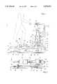
- FIG. 1is an elevation view of the preferred embodiment of the present invention.
- FIG. 2is a plan view of the preferred embodiment of the present invention.
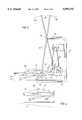
- FIG. 3is an elevation view of the preferred embodiment of the present invention having arm members.
- FIG. 4is a detail view of a portion of the present invention.
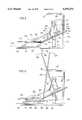
- FIG. 5is an elevation view of an alternate embodiment of the present invention.
- FIG. 6is an elevation view of the alternate embodiment of the present invention shown in FIG. 4 having arm members.
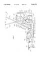
- FIG. 7is an elevation view of yet another alternate embodiment of the present invention.
- a frame 10comprising a base portion 12, a mid portion 14, and a top portion 16.
- the frame 10comprises two bottom portions 12a and 12b, two mid portions 14a and 14b, and two top portions (not shown).
- the frameis comprised of two separate bents "a" and "b".
- variationscan be made to frame 10 as disclosed without departing from the spirit of the invention.
- a coupling system 20is fixed relative to the frame and comprises a pulley 22, crank members 24, resistant brake 23, sheave 28 and belt 30.
- Two reciprocating members 32are positioned in the lower proximity of frame 10. Each reciprocating member 32 has one end 34 which is adapted to move laterally in a linear direction as shown in FIG. 1 by arrow 100.
- a roller 36is mounted at each end 34 of reciprocating member 32 and is adapted, as shown in FIG. 1, to ride on base portion 12 of frame 10. Alternatively, roller 36 may directly engage the floor, if desirable.
- the other end 38 of each reciprocating member 32is pivotally connected to one end of a crank 24. The pivotal connection at end 38 may be through a journal member 25 (see FIG.
- crank 24which extends from the end of crank 24 through an aperture in end 38 of each reciprocating member 32 and attaches to one end of a link 42 of linkage assembly 40 as discussed below.
- the other end of crank 24is attached to pulley 22 at pivot axis 26 of coupling system 20.
- Pulley 22revolves about axis 26.
- the preferred embodimentmay include a handle portion 17 which is an integral part of top portion 16 of frame 10.
- each linkage assembly 40comprises two primary links 42 and 44.
- Link 42is fixed at one end to journal member 25 and is pivotally connected at its other end 41 to link 44.
- Link 44comprises two portions--a bent portion 45 and a telescoping portion 46.
- One end of bent portion 45reciprocates within telescoping portion 46.
- a foot platform or foot pad 50is attached to telescoping portion 46 of link 44 proximate end 51 of link 44.
- each arm memberincludes a handle portion 82 which is gripped by the user during the operation of the apparatus.
- the other end of each arm member 80reciprocates within a sleeve 84.
- Sleeve 84is pivotally attached to telescoping portion 46 through pivot point 85.
- Each arm member 80is pivotally connected at pivot point 96 to the top portion 16 of frame 10. During operation of the apparatus, arm member 80 pivots about point 96 and thereby slides vertically relative to sleeve 84 as link 44 revolves in accordance with the present invention as described below.
- the user "U”ascends the present invention from the back or the sides which facilitate its use.
- ascending and descendingis difficult and cumbersome due to the location of the pulleys and of the structure.
- a climbing motion by the userresults in the displacement of first ends 34 of each reciprocating member 32 in the direction of arrow 100.
- a circular motionoccurs at the second end 38 of each reciprocating member 32 as shown in phantom by circle 105.
- the motiongradually changes from a circular motion (at ends 38) to a linear motion at ends 34.
- This geometric transitionoccurs in the form of an approximate ellipse. It is not a perfect elliptical shape; it tends to be slightly more egg-shaped. However, it provides a more natural and rhythmic body movement.
- journal member 25results in a similar circular motion of the outer end of links 42 since each crank 24 and link 42 are fixed relative to one another through journal member 25.
- Thiscauses pivot connection 41 to rotate in a circle about axis 26 as shown in phantom as circle 103.
- two concurrently circular motionsoccur as shown by circles 103 and 105.
- Such dual circular motiontranslates to a substantially elliptical shape as shown by ellipse 102 at foot platforms 50 yet permits each foot platform 50 to remain substantially parallel with a reference plane, which in the case of FIG. 1 is shown as the floor "F" or base portion 12, during such elliptical movement of foot platform 50.
- foot platform 50may be initially oriented at an angle relative to a reference plane other than the floor by bending the end of portion 46 or including a wedge under each platform 50. In either event, the present invention still provides that the foot platforms 51 remains substantially parallel to a reference plane "R" as shown in FIG. 4.
- the armsare used to oscillate handle portions 82 in an arcuate path as shown by arrow 104.
- the arc of arrow 104is defined by the radius of a circle extending from pivot point 96 to handle portions 82.
- resistant brake 23 of coupling system 20operates in a manner well-known to those skilled in the art. Resistant brake 23 serves to increase or decrease the load on the pulley through the sheave point 28/belt 30 arrangement. Coupling system 20 is secured to base portion 12 of frame 10 through plate 31. Similarly, resistant brake 23 is secured to mid portion 14 of frame 10 through bracket 27.
- Frame 110comprises a base portion 112, a mid portion 114, and a top portion 116.
- a coupling system 120is included having identical components of the coupling system 20 described above for the preferred embodiment. Furthermore, coupling system 120 performs in an identical manner to coupling system 20 described above for the preferred embodiment.
- a pair of reciprocating members 132are also included, each having a first end 134 on which rollers 136 are mounted.
- the second end 138 of each reciprocating member 132is pivotally connected via a journal member 125 to one end of each crank 124.
- two linkage assemblies 140are included, each having a first link 142 and a second link 144.
- Each link 144supports a foot platform 150 over end 151.
- each link 144is pivotally connected, preferably in front of foot platform 150 to a reciprocating member 132 proximal end 134 at connection 143.
- Link 142is fixed at one end to journal member 125.
- each link 142is fixed relative to corresponding crank member 124.
- the other end of each link 142includes a roller 141 which engages portion 145 of link 144.
- a handle portion 117is available to be gripped by the user.
- Each arm member 180includes two links 181 and 182.
- Link 181is pivotally connected at pivot connection 196 to top portion 116 of frame 110.
- the other end of each link 181is pivotally connected at connection 183 to one end of link 182.
- the other end of link 182is pivotally connected at pivot point 185 to end 134 of a reciprocating member 132.
- Each link 181includes a handle portion 182 which the operator grips during operation of the apparatus.
- each reciprocating member 132is displaced in a linear manner in the direction of arrow 200.
- end 138 of each reciprocating member 132moves in a circular motion about axis 126 as shown in phantom by circle 105 (see FIG. 1).
- FIG. 7another alternate embodiment is shown. As in the case of the previous embodiments, similar structure will be referred to with the same two-digit reference numeral when possible but with a 200 series prefix.
- Frame 210comprises a base portion 212, a mid portion 214 and a top portion 216.
- a coupler system 220is shown which includes the same components and functions identical with the coupling system 20 of the preferred embodiment.
- Two reciprocating members 232are included, each having a first end 234 to which a roller 236 is attached. The other end 238 of each reciprocating member 232 is pivotally connected to one end of a crank 224 of coupling system 220.
- this alternate embodimentincludes two identical link assemblies 240.
- Each link assembly 240includes two pairs of links 242A/B and 244A/B. As shown, link 242A is pivotally mounted parallel with link 242B, and link 244A is pivotally mounted parallel to link 244B.
- a foot platform pedal structure 252is pivotally attached to ends 251 of links 244A/B at pivot connections 243A/B. Foot platform pedal 242 is also pivotally attached to end 234 of reciprocating member 232 through pivoted connection 243A.
- Links 244A/Bare pivotally connected at ends 245 to a pivot plate 243.
- Links 244A/Bare pivotally connected at one end through pivot connections 241A/B to pivot plate 243.
- the other end of link 242Bis pivotally connected at pivot point 296B to top portion 216 of frame 210.
- Link 242Ais pivotally connected through pivot connection 296A to the top portion 216 of frame 210 as well. However, the connection at 296A is not the upper end of link 296A. Rather, as shown, link 242A extends upwardly therefrom and includes a handle portion 282 at its opposite end which is used by the operator.
- Each foot platform pedal 252includes a foot platform 250 on which the user places his foot during operation of the apparatus.
- this alternate embodimentincludes a resistant brake 223 which serves to increase or decrease the load on the pulley 222 of coupling system 220 through the sheave 228/belt 230 arrangement.
- Resistant brake 223 in combination with the sheave 228/belt 230 arrangementoperates in the identical manner to resistant brake 23 and sheave 28/belt 30 of the preferred embodiment as discussed above.
- coupling system 220is mounted to base portion 212 by a plate 231.
- resistant brake 223is mounted to mid portion 214 of frame 220 by a plate 227.
- the userascends the device from the side or the rear and begins the climbing motion using foot platforms 250.
- the useralso grabs handle portions 282 and begins an oscillating motion. Since each link 242A is pivotally connected at connection 296A, the handle portions define an arcuate path as shown by arrow 304.
- foot platforms 250define a substantially elliptical path as shown by path 302.
- the movement of linkage assemblies 240maintains foot platform 250 substantially parallel with the floor or other reference plane at all times while the foot platform revolves through elliptical path 302. As in the case of the preferred embodiment and as shown in FIGS.
- each pedal 252may be selected to orient each platform 250 and an acute angle relative to the floor but parallel to one another and a reference plane "R".
- each platformrevolves in a substantially elliptical path but each such platform 250 remains substantially parallel to a reference plane as it revolves through path 302.
- Each linkage assembly 240comprises two parallelograms, the first defined by parallel links 242A/B, top portion 216 between connections 296A/B, and the pivot plate 243 between pivot connections 241A/B.
- the second parallelogramis defined by links 244A/B, foot platform pedal 252 and pivot plate 243.
- the climbing motion which the operator imposes on platforms 250serves to revolve point 225 in a circular path about axis 226.
- Linkage assemblies 240serve to ensure that foot platforms 250 remain substantially parallel with the floor or a reference plane as it revolves in the predetermined substantially elliptical path 302.
- An improved stationary exercising deviceis disclosed in the foregoing preferred and alternate embodiments which maximizes cardiovascular exercise yet minimizes stress on critical joints through the use of linkages which define a predetermined substantially elliptical path that more accurately simulates natural and rhythmic body movement coupled with movement of a foot platform which remains substantially parallel with the floor. Keeping the foot platform substantially parallel with a reference plane, such as the floor, is beneficial since users would anticipate that the step or platform surface will remain at the same angular orientation during its revolution through the substantially elliptical path.
Landscapes
- Engineering & Computer Science (AREA)
- Health & Medical Sciences (AREA)
- Chemical & Material Sciences (AREA)
- Combustion & Propulsion (AREA)
- Transportation (AREA)
- Mechanical Engineering (AREA)
- Cardiology (AREA)
- Vascular Medicine (AREA)
- General Health & Medical Sciences (AREA)
- Physical Education & Sports Medicine (AREA)
- Rehabilitation Tools (AREA)
Abstract
Description
Claims (30)
Priority Applications (13)
| Application Number | Priority Date | Filing Date | Title |
|---|---|---|---|
| US08/497,612US5593372A (en) | 1995-01-25 | 1995-06-30 | Stationary exercise apparatus having a preferred foot platform path |
| JP08523025AJP3038242B2 (en) | 1995-01-25 | 1996-01-25 | Stationary exercise equipment |
| EP07006301AEP1818082A3 (en) | 1995-01-25 | 1996-01-25 | Stationary exercise apparatus |
| CN 96192690CN1230229C (en) | 1995-01-25 | 1996-01-25 | fitness equipment for fitness |
| HK99102479.8AHK1017282B (en) | 1995-01-25 | 1996-01-25 | An exercise apparatus for exercising |
| PCT/US1996/001101WO1996022814A1 (en) | 1995-01-25 | 1996-01-25 | Stationary exercise apparatus |
| EP96905240AEP0805708B1 (en) | 1995-01-25 | 1996-01-25 | Stationary exercise apparatus |
| CA002211127ACA2211127C (en) | 1995-01-25 | 1996-01-25 | Stationary exercise apparatus |
| AU49050/96AAU4905096A (en) | 1995-01-25 | 1996-01-25 | Stationary exercise apparatus |
| EP07006300AEP1818081A3 (en) | 1995-01-25 | 1996-01-25 | Stationary exercise apparatus |
| DE69636995TDE69636995T2 (en) | 1995-01-25 | 1996-01-25 | FIXED EXERCISE DEVICE |
| US08/665,724US5766113A (en) | 1995-01-25 | 1996-06-18 | Stationary exercise apparatus having a preferred foot platform path |
| US09/438,509USRE38803E1 (en) | 1995-01-25 | 1999-11-12 | Stationary exercise apparatus having a preferred foot platform path |
Applications Claiming Priority (2)
| Application Number | Priority Date | Filing Date | Title |
|---|---|---|---|
| US08/377,846US5573480A (en) | 1995-01-25 | 1995-01-25 | Stationary exercise apparatus |
| US08/497,612US5593372A (en) | 1995-01-25 | 1995-06-30 | Stationary exercise apparatus having a preferred foot platform path |
Related Parent Applications (1)
| Application Number | Title | Priority Date | Filing Date |
|---|---|---|---|
| US08/377,846Continuation-In-PartUS5573480A (en) | 1995-01-25 | 1995-01-25 | Stationary exercise apparatus |
Related Child Applications (1)
| Application Number | Title | Priority Date | Filing Date |
|---|---|---|---|
| US08/665,724ContinuationUS5766113A (en) | 1995-01-25 | 1996-06-18 | Stationary exercise apparatus having a preferred foot platform path |
Publications (1)
| Publication Number | Publication Date |
|---|---|
| US5593372Atrue US5593372A (en) | 1997-01-14 |
Family
ID=27007986
Family Applications (2)
| Application Number | Title | Priority Date | Filing Date |
|---|---|---|---|
| US08/497,612Expired - LifetimeUS5593372A (en) | 1995-01-25 | 1995-06-30 | Stationary exercise apparatus having a preferred foot platform path |
| US08/665,724CeasedUS5766113A (en) | 1995-01-25 | 1996-06-18 | Stationary exercise apparatus having a preferred foot platform path |
Family Applications After (1)
| Application Number | Title | Priority Date | Filing Date |
|---|---|---|---|
| US08/665,724CeasedUS5766113A (en) | 1995-01-25 | 1996-06-18 | Stationary exercise apparatus having a preferred foot platform path |
Country Status (1)
| Country | Link |
|---|---|
| US (2) | US5593372A (en) |
Cited By (114)
| Publication number | Priority date | Publication date | Assignee | Title |
|---|---|---|---|---|
| US5743834A (en)* | 1995-01-25 | 1998-04-28 | Rodgers, Jr.; Robert E. | Stationary exercise apparatus with adjustable crank |
| US5769760A (en)* | 1997-07-22 | 1998-06-23 | Lin; Michael | Stationary exercise device |
| US5782722A (en)* | 1997-08-27 | 1998-07-21 | Sands; Lenny | Structure of folding collapsible step exerciser |
| US5830112A (en)* | 1997-10-16 | 1998-11-03 | Greenmaster Industrial Corp. | Foldable jogging simulator |
| US5836854A (en)* | 1998-02-10 | 1998-11-17 | Kuo; Hai Pin | Roaming excerciser |
| US5879271A (en)* | 1997-04-15 | 1999-03-09 | Stearns; Kenneth W. | Exercise method and apparatus |
| USD408477S (en)* | 1998-04-09 | 1999-04-20 | Precor Incorporated | Stationary exercise device |
| US5895339A (en)* | 1995-06-30 | 1999-04-20 | Maresh; Joseph D. | Elliptical exercise methods and apparatus |
| US5897463A (en)* | 1995-06-30 | 1999-04-27 | Maresh; Joseph D. | Four bar exercise machine |
| US5899833A (en)* | 1996-06-17 | 1999-05-04 | Brunswick Corporation | Orbital stepping exercise apparatus |
| US5910072A (en)* | 1997-12-03 | 1999-06-08 | Stairmaster Sports/Medical Products, Inc. | Exercise apparatus |
| USD410978S (en)* | 1996-07-12 | 1999-06-15 | Precor Incorporated | Cross training exerciser |
| US5916065A (en)* | 1998-02-10 | 1999-06-29 | Stamina Products, Inc. | Multiple leg movement exercise apparatus |
| US5919118A (en)* | 1997-12-16 | 1999-07-06 | Stearns; Kenneth W. | Elliptical exercise methods and apparatus |
| US5921894A (en)* | 1997-10-21 | 1999-07-13 | Eschenbach; Paul William | Compact elliptical exercise apparatus |
| US5957814A (en)* | 1997-06-09 | 1999-09-28 | Eschenbach; Paul William | Orbital exercise apparatus with arm exercise |
| US5989159A (en)* | 1998-01-22 | 1999-11-23 | Chen; James | Exercise device |
| US5997445A (en)* | 1997-08-19 | 1999-12-07 | Maresh; Joseph D. | Elliptical exercise methods and apparatus |
| US6019710A (en)* | 1998-01-06 | 2000-02-01 | Icon Health & Fitness, Inc. | Exercising device with elliptical movement |
| US6036622A (en)* | 1997-10-10 | 2000-03-14 | Gordon; Joel D. | Exercise device |
| US6146314A (en)* | 1998-05-15 | 2000-11-14 | Stamina Products, Inc. | Pedal-type exerciser |
| US6146313A (en)* | 1995-12-07 | 2000-11-14 | Precor Incorporated | Cross training exercise device |
| US6149551A (en)* | 1998-05-12 | 2000-11-21 | Epix, Inc. | Foldable elliptical exercise machine |
| US6165107A (en)* | 1999-03-18 | 2000-12-26 | Illinois Tool Works Inc. | Flexibly coordinated motion elliptical exerciser |
| US6171217B1 (en) | 1999-02-09 | 2001-01-09 | Gordon L. Cutler | Convertible elliptical and recumbent cycle |
| US6176814B1 (en) | 1996-06-17 | 2001-01-23 | Brunswick Corporation | Cross training exercise apparatus |
| US6183398B1 (en) | 1998-07-23 | 2001-02-06 | Unisen, Inc. | Exercise trainer with a stride multiplier |
| US6206806B1 (en) | 2000-03-31 | 2001-03-27 | Yong S. Chu | Elliptical motion exerciser |
| US6217486B1 (en) | 1999-06-15 | 2001-04-17 | Brunswick Corporation | Elliptical step exercise apparatus |
| US6238321B1 (en) | 1999-10-14 | 2001-05-29 | Illinois Tool Works, Inc. | Exercise device |
| US6248045B1 (en) | 1997-03-31 | 2001-06-19 | Kenneth W. Stearns | Exercise method and apparatus |
| US20020049122A1 (en)* | 1998-07-23 | 2002-04-25 | Fred Mercado | Exercise and therapeutic trainer |
| US6398695B2 (en) | 1998-09-24 | 2002-06-04 | Larry Miller | Elliptical exercise device |
| US6416442B1 (en) | 1997-05-05 | 2002-07-09 | Kenneth W. Stearns | Elliptical exercise method and apparatus |
| US20020155927A1 (en)* | 1998-07-23 | 2002-10-24 | Corbalis Kevin P. | Elliptical exercise device and arm linkage |
| US6511402B2 (en) | 1994-05-25 | 2003-01-28 | Unisen, Inc. | Power controlled exercising machine and method for controlling the same |
| US6626802B1 (en) | 1999-12-22 | 2003-09-30 | Robert E. Rodgers, Jr. | Stationary type of exercise apparatus that enables movement of the user's feet in a reciprocating motion |
| US6689019B2 (en) | 2001-03-30 | 2004-02-10 | Nautilus, Inc. | Exercise machine |
| US20040058784A1 (en)* | 2001-07-11 | 2004-03-25 | Roberts Robert E. | Stationary type of exercise apparatus that enables movement of the user's feet in a reciprocating motion |
| US20040077463A1 (en)* | 2002-02-26 | 2004-04-22 | Rodgers Robert E. | Stationary exercise apparatus with pivoting foot platforms |
| US6752744B2 (en) | 1999-10-14 | 2004-06-22 | Precor Incorporated | Exercise device |
| US20040157706A1 (en)* | 2003-02-06 | 2004-08-12 | Miller Larry D. | Non-reciprocating exercise device |
| US20040248707A1 (en)* | 2003-06-06 | 2004-12-09 | Rodgers Robert E. | Compact variable path exercise apparatus with a relatively long cam surface |
| WO2004108225A1 (en) | 2003-06-06 | 2004-12-16 | Rodgers Robert E Jr | Variable stride exercise apparatus |
| US20040266587A1 (en)* | 2003-06-27 | 2004-12-30 | Miller Larry D. | Elliptical exercise device with movable pivot axis |
| US20040266588A1 (en)* | 2003-06-27 | 2004-12-30 | Miller Larry D. | Elliptical exercise device with modified foot action |
| US20050009668A1 (en)* | 2003-07-10 | 2005-01-13 | Greg Savettiere | Elliptical/treadmill exercise apparatus |
| US20050026752A1 (en)* | 2003-06-23 | 2005-02-03 | Nautilus, Inc. | Variable stride exercise device |
| US6855093B2 (en) | 2001-07-12 | 2005-02-15 | Brunswick Corporation | Stairclimber apparatus pedal mechanism |
| US20050164835A1 (en)* | 2004-01-23 | 2005-07-28 | Porth Timothy J. | Exercise equipment with automatic adjustment of stride length and/or stride height based upon direction of foot support rotation |
| US20050181911A1 (en)* | 2004-02-18 | 2005-08-18 | Porth Timothy J. | Exercise equipment with automatic adjustment of stride length and/or stride height based upon speed of foot support |
| US6939271B1 (en) | 1995-12-07 | 2005-09-06 | Precor Incorporated | Crosstraining exercise device |
| US20050202939A1 (en)* | 2003-06-23 | 2005-09-15 | Nautilus, Inc. | Variable stride exercise device |
| US20060003868A1 (en)* | 2003-06-23 | 2006-01-05 | Nautilus, Inc. | Releasable connection mechanism for variable stride exercise devices |
| US20060035755A1 (en)* | 2004-08-11 | 2006-02-16 | Dalebout William T | Elliptical exercise machine with integrated anaerobic exercise system |
| US20060100066A1 (en)* | 1995-06-30 | 2006-05-11 | Maresh Joseph D | Exercise methods and apparatus |
| US20060189447A1 (en)* | 2005-02-09 | 2006-08-24 | Precor Incorporated | Adjustable total body cross-training exercise device |
| US7097593B2 (en) | 2003-08-11 | 2006-08-29 | Nautilus, Inc. | Combination of treadmill and stair climbing machine |
| US20060287161A1 (en)* | 2004-08-11 | 2006-12-21 | Dalebout William T | Foldable elliptical exercise machine |
| US7169088B2 (en) | 2003-06-06 | 2007-01-30 | Rodgers Jr Robert E | Compact variable path exercise apparatus |
| US20070037667A1 (en)* | 2005-08-11 | 2007-02-15 | Gordon Joel D | Exercise device |
| US7201705B2 (en) | 2003-06-06 | 2007-04-10 | Rodgers Jr Robert E | Exercise apparatus with a variable stride system |
| US7214168B2 (en) | 2003-06-06 | 2007-05-08 | Rodgers Jr Robert E | Variable path exercise apparatus |
| US7244217B2 (en) | 2003-06-06 | 2007-07-17 | Rodgers Jr Robert E | Exercise apparatus that allows user varied stride length |
| DE102006036114A1 (en)* | 2006-08-02 | 2008-02-07 | Forhouse Corp., Daya | Training device i.e. home trainer, for providing sequences of movements, has base plates attached to two parallelogram-connecting mechanisms, which hold base plates in fixed inclinations during entire movement |
| US20080200314A1 (en)* | 2007-02-20 | 2008-08-21 | Icon Health And Fitness, Inc. | One-step foldable elliptical exercise machine |
| US7448986B1 (en) | 2004-02-18 | 2008-11-11 | Octane Fitness, Llc | Exercise equipment with automatic adjustment of stride length and/or stride height based upon the heart rate of a person exercising on the exercise equipment |
| US20080280731A1 (en)* | 2007-05-08 | 2008-11-13 | Icon Health & Fitness, Inc. | Elliptical exercise machine with adjustable foot motion |
| US20080300114A1 (en)* | 2007-06-04 | 2008-12-04 | Dalebout William T | Elliptical exercise machine with adjustable ramp |
| US7540827B1 (en)* | 1997-04-24 | 2009-06-02 | Stearns Kenneth W | Elliptical exercise methods and apparatus |
| US7658698B2 (en) | 2006-08-02 | 2010-02-09 | Icon Ip, Inc. | Variable stride exercise device with ramp |
| US20100105528A1 (en)* | 2004-06-04 | 2010-04-29 | Christiaan Ditolla | Verticle exercise cycle |
| US7717828B2 (en) | 2006-08-02 | 2010-05-18 | Icon Ip, Inc. | Exercise device with pivoting assembly |
| US8409058B2 (en) | 2006-08-10 | 2013-04-02 | Exerciting, Llc | Varied gait exercise device with pivot bar transfer system |
| US8647240B2 (en) | 2010-10-08 | 2014-02-11 | Innovative Applications, Inc. | Exercise device |
| USD742977S1 (en) | 2013-08-29 | 2015-11-10 | Octane Fitness, Llc | Stationary exercise machine |
| US9186551B1 (en)* | 2014-07-29 | 2015-11-17 | Allen D. Smith | Crawling exercise device |
| US9199115B2 (en) | 2013-03-15 | 2015-12-01 | Nautilus, Inc. | Exercise machine |
| US9364708B2 (en) | 2013-08-29 | 2016-06-14 | Octane Fitness, Llc | Lower body mimetic exercise device with fully or partially autonomous right and left leg links and ergonomically positioned pivot points |
| US20170056717A1 (en)* | 2015-08-28 | 2017-03-02 | Icon Health & Fitness, Inc. | Pedal Path of a Stepping Machine |
| US20170056709A1 (en)* | 2015-08-28 | 2017-03-02 | Icon Health & Fitness, Inc. | Pedal Path of a Stepping Machine |
| US20170106231A1 (en)* | 2005-11-04 | 2017-04-20 | Johnson Health Tech. Co., Ltd. | Stationary exercise apparatus |
| EP3178529A1 (en)* | 2015-12-08 | 2017-06-14 | Mario Contenti Designs Co., Ltd. | Elliptical trainer with changeable foot motion |
| USD792530S1 (en) | 2015-09-28 | 2017-07-18 | Nautilus, Inc. | Elliptical exercise machine |
| US9950209B2 (en) | 2013-03-15 | 2018-04-24 | Nautilus, Inc. | Exercise machine |
| US9993680B2 (en) | 2014-12-10 | 2018-06-12 | Fit-Novation, Inc. | Exercise device |
| US10039953B2 (en) | 2015-04-27 | 2018-08-07 | Prosnitz Solutions Llc | Cycle-type exercise equipment conversion apparatus and methods of converting thereof |
| US10046197B2 (en) | 2015-11-19 | 2018-08-14 | Fitnovation, Inc. | Exercise device |
| US10188890B2 (en) | 2013-12-26 | 2019-01-29 | Icon Health & Fitness, Inc. | Magnetic resistance mechanism in a cable machine |
| US10252109B2 (en) | 2016-05-13 | 2019-04-09 | Icon Health & Fitness, Inc. | Weight platform treadmill |
| US10258828B2 (en) | 2015-01-16 | 2019-04-16 | Icon Health & Fitness, Inc. | Controls for an exercise device |
| US10272317B2 (en) | 2016-03-18 | 2019-04-30 | Icon Health & Fitness, Inc. | Lighted pace feature in a treadmill |
| US10279212B2 (en) | 2013-03-14 | 2019-05-07 | Icon Health & Fitness, Inc. | Strength training apparatus with flywheel and related methods |
| US10293211B2 (en) | 2016-03-18 | 2019-05-21 | Icon Health & Fitness, Inc. | Coordinated weight selection |
| US10343017B2 (en) | 2016-11-01 | 2019-07-09 | Icon Health & Fitness, Inc. | Distance sensor for console positioning |
| US10376736B2 (en) | 2016-10-12 | 2019-08-13 | Icon Health & Fitness, Inc. | Cooling an exercise device during a dive motor runway condition |
| US10426989B2 (en) | 2014-06-09 | 2019-10-01 | Icon Health & Fitness, Inc. | Cable system incorporated into a treadmill |
| US10433612B2 (en) | 2014-03-10 | 2019-10-08 | Icon Health & Fitness, Inc. | Pressure sensor to quantify work |
| US10441844B2 (en) | 2016-07-01 | 2019-10-15 | Icon Health & Fitness, Inc. | Cooling systems and methods for exercise equipment |
| US10471299B2 (en) | 2016-07-01 | 2019-11-12 | Icon Health & Fitness, Inc. | Systems and methods for cooling internal exercise equipment components |
| US10493349B2 (en) | 2016-03-18 | 2019-12-03 | Icon Health & Fitness, Inc. | Display on exercise device |
| US10500473B2 (en) | 2016-10-10 | 2019-12-10 | Icon Health & Fitness, Inc. | Console positioning |
| US10543395B2 (en) | 2016-12-05 | 2020-01-28 | Icon Health & Fitness, Inc. | Offsetting treadmill deck weight during operation |
| US10561891B2 (en) | 2017-05-26 | 2020-02-18 | Nautilus, Inc. | Exercise machine |
| US10561894B2 (en) | 2016-03-18 | 2020-02-18 | Icon Health & Fitness, Inc. | Treadmill with removable supports |
| US10625114B2 (en) | 2016-11-01 | 2020-04-21 | Icon Health & Fitness, Inc. | Elliptical and stationary bicycle apparatus including row functionality |
| US10625137B2 (en) | 2016-03-18 | 2020-04-21 | Icon Health & Fitness, Inc. | Coordinated displays in an exercise device |
| US20200121982A1 (en)* | 2018-10-18 | 2020-04-23 | Chao-Chi Yu | Elliptical machine |
| US10661114B2 (en) | 2016-11-01 | 2020-05-26 | Icon Health & Fitness, Inc. | Body weight lift mechanism on treadmill |
| US10729965B2 (en) | 2017-12-22 | 2020-08-04 | Icon Health & Fitness, Inc. | Audible belt guide in a treadmill |
| US10953305B2 (en) | 2015-08-26 | 2021-03-23 | Icon Health & Fitness, Inc. | Strength exercise mechanisms |
| US11198033B2 (en) | 2013-03-15 | 2021-12-14 | Nautilus, Inc. | Exercise machine |
| US11451108B2 (en) | 2017-08-16 | 2022-09-20 | Ifit Inc. | Systems and methods for axial impact resistance in electric motors |
| US11786781B2 (en) | 2015-04-27 | 2023-10-17 | Prosnitz Solutions Llc | Combination stationary exercise equipment |
Families Citing this family (22)
| Publication number | Priority date | Publication date | Assignee | Title |
|---|---|---|---|---|
| US6045487A (en)* | 1996-02-08 | 2000-04-04 | Miller; Larry | Exercise apparatus |
| US6099439A (en)* | 1996-06-17 | 2000-08-08 | Brunswick Corporation | Cross training exercise apparatus |
| US5865712A (en)* | 1998-01-16 | 1999-02-02 | Chang; Major | Walking exerciser |
| GB2369586B (en)* | 2000-12-02 | 2004-09-22 | Rock Merchanting Ltd | Exercise apparatus |
| DE20219403U1 (en)* | 2002-12-14 | 2003-03-13 | Lai, Fen-Ying, Taichung | stages simulator |
| US6966869B1 (en)* | 2003-06-26 | 2005-11-22 | Stearns Kenneth W | Exercise methods and apparatus with elliptical foot motion |
| US7544152B2 (en)* | 2004-07-30 | 2009-06-09 | Unisen, Inc. | Linkage based exercise machine |
| WO2006015291A2 (en) | 2004-07-30 | 2006-02-09 | Unisen, Inc, Dba Star Trac | Articulating linkage exercise machine |
| TW200609017A (en)* | 2004-09-01 | 2006-03-16 | Johnson Health Tech Co Ltd | Elliptical exerciser |
| US20060116247A1 (en)* | 2004-12-01 | 2006-06-01 | Precor, Inc. | Total body elliptical exercise equipment with upper body monitoring |
| TWM283655U (en)* | 2005-08-19 | 2005-12-21 | Cycling & Health Tech Ind R&D | Elliptic sport machine with orbit-adjusting function |
| US7455628B1 (en)* | 2006-01-21 | 2008-11-25 | Stearns Kenneth W | Elliptical exercise methods and apparatus |
| US7749137B2 (en)* | 2006-11-16 | 2010-07-06 | Nautilus, Inc. | Variable stride exercise device |
| US7507186B2 (en)* | 2007-03-14 | 2009-03-24 | Stearns Kenneth W | Exercise methods and apparatus with elliptical foot motion |
| KR100831240B1 (en)* | 2008-02-18 | 2008-05-22 | 주식회사 모투스 | Pedal arc track exercise equipment |
| TW201240700A (en)* | 2011-04-14 | 2012-10-16 | Johnson Health Tech Co Ltd | Sport facility |
| CN103357143B (en)* | 2012-03-26 | 2016-06-01 | 乔山健康科技(上海)有限公司 | Sports equipment |
| US8979714B2 (en)* | 2013-05-07 | 2015-03-17 | Larry D. Miller Trust | Elliptical exercise device |
| CN106799005A (en)* | 2015-11-26 | 2017-06-06 | 孟乔企业有限公司 | Elliptical machine with real-time motion stroke changing function |
| USD949255S1 (en) | 2019-02-18 | 2022-04-19 | Paul Hsieh | Mini stepper with flat steps |
| US11318342B2 (en)* | 2019-03-20 | 2022-05-03 | Paradigm Health and Wellness | Mini stepper with flat steps |
| TWI707711B (en)* | 2019-12-17 | 2020-10-21 | 清河國際股份有限公司 | Link mechanism of elliptical motion track |
Citations (31)
| Publication number | Priority date | Publication date | Assignee | Title |
|---|---|---|---|---|
| US219439A (en)* | 1879-09-09 | Improvement in passive-motion walking-machines | ||
| US2603486A (en)* | 1948-07-23 | 1952-07-15 | Joseph Borroughs | Push and pull exerciser |
| US3316898A (en)* | 1964-10-23 | 1967-05-02 | James W Brown | Rehabilitation and exercise apparatus |
| US3432164A (en)* | 1967-02-14 | 1969-03-11 | Hugh A Deeks | Exercising machine |
| US3759511A (en)* | 1971-03-29 | 1973-09-18 | K Gustafson | Adjustable friction type exercising device |
| US4053173A (en)* | 1976-03-23 | 1977-10-11 | Chase Sr Douglas | Bicycle |
| US4188030A (en)* | 1976-10-18 | 1980-02-12 | Repco Limited | Cycle exerciser |
| DE2919494A1 (en)* | 1979-05-15 | 1980-11-20 | Kuemmerlin | Training appts. with tread crank - has tread plates linked to each crank web in axis-parallel manner, and supported at other end by rollers |
| US4379566A (en)* | 1981-01-26 | 1983-04-12 | Creative Motion Industries, Inc. | Operator powered vehicle |
| US4456276A (en)* | 1981-04-15 | 1984-06-26 | Peter Bortolin | Bicycle assembly |
| US4509742A (en)* | 1983-06-06 | 1985-04-09 | Cones Charles F | Exercise bicycle |
| US4555109A (en)* | 1983-09-14 | 1985-11-26 | Hartmann Joseph C | Exercising machine |
| US4561318A (en)* | 1981-10-05 | 1985-12-31 | Schirrmacher Douglas R | Lever power system |
| US4645200A (en)* | 1985-05-28 | 1987-02-24 | Hix William R | Isometric exercising device |
| US4679786A (en)* | 1986-02-25 | 1987-07-14 | Rodgers Robert E | Universal exercise machine |
| US4720093A (en)* | 1984-06-18 | 1988-01-19 | Del Mar Avionics | Stress test exercise device |
| US4869494A (en)* | 1989-03-22 | 1989-09-26 | Lambert Sr Theodore E | Exercise apparatus for the handicapped |
| US4900013A (en)* | 1988-01-27 | 1990-02-13 | Rodgers Jr Robert E | Exercise apparatus |
| US4949993A (en)* | 1989-07-31 | 1990-08-21 | Laguna Tectrix, Inc. | Exercise apparatus having high durability mechanism for user energy transmission |
| US4949954A (en)* | 1989-05-04 | 1990-08-21 | Hix William R | Jointed bicycle-simulation device for isometric exercise |
| US4989857A (en)* | 1990-06-12 | 1991-02-05 | Kuo Hai Pin | Stairclimber with a safety speed changing device |
| US5039087A (en)* | 1990-05-11 | 1991-08-13 | Kuo Hai Pin | Power stairclimber |
| US5039088A (en)* | 1990-04-26 | 1991-08-13 | Shifferaw Tessema D | Exercise machine |
| US5131895A (en)* | 1988-01-27 | 1992-07-21 | Rogers Jr Robert E | Exercise apparatus |
| US5135447A (en)* | 1988-10-21 | 1992-08-04 | Life Fitness | Exercise apparatus for simulating stair climbing |
| US5186697A (en)* | 1989-01-31 | 1993-02-16 | Rennex Brian G | Bi-directional stair/treadmill/reciprocating-pedal exerciser |
| US5242343A (en)* | 1992-09-30 | 1993-09-07 | Larry Miller | Stationary exercise device |
| US5290211A (en)* | 1992-10-29 | 1994-03-01 | Stearns Technologies, Inc. | Exercise device |
| US5295928A (en)* | 1989-01-31 | 1994-03-22 | Rennex Brian G | Bi-directional stair/treadmill/reciprocating-pedal exerciser |
| US5299993A (en)* | 1992-12-01 | 1994-04-05 | Pacific Fitness Corporation | Articulated lower body exerciser |
| US5423729A (en)* | 1994-08-01 | 1995-06-13 | Eschenbach; Paul W. | Collapsible exercise machine with arm exercise |
Family Cites Families (2)
| Publication number | Priority date | Publication date | Assignee | Title |
|---|---|---|---|---|
| US5573480A (en)* | 1995-01-25 | 1996-11-12 | Ccs, Llc | Stationary exercise apparatus |
| US5540637A (en)* | 1995-01-25 | 1996-07-30 | Ccs, Llc | Stationary exercise apparatus having a preferred foot platform orientation |
- 1995
- 1995-06-30USUS08/497,612patent/US5593372A/ennot_activeExpired - Lifetime
- 1996
- 1996-06-18USUS08/665,724patent/US5766113A/ennot_activeCeased
Patent Citations (34)
| Publication number | Priority date | Publication date | Assignee | Title |
|---|---|---|---|---|
| US219439A (en)* | 1879-09-09 | Improvement in passive-motion walking-machines | ||
| US2603486A (en)* | 1948-07-23 | 1952-07-15 | Joseph Borroughs | Push and pull exerciser |
| US3316898A (en)* | 1964-10-23 | 1967-05-02 | James W Brown | Rehabilitation and exercise apparatus |
| US3432164A (en)* | 1967-02-14 | 1969-03-11 | Hugh A Deeks | Exercising machine |
| US3759511A (en)* | 1971-03-29 | 1973-09-18 | K Gustafson | Adjustable friction type exercising device |
| US4053173A (en)* | 1976-03-23 | 1977-10-11 | Chase Sr Douglas | Bicycle |
| US4188030A (en)* | 1976-10-18 | 1980-02-12 | Repco Limited | Cycle exerciser |
| DE2919494A1 (en)* | 1979-05-15 | 1980-11-20 | Kuemmerlin | Training appts. with tread crank - has tread plates linked to each crank web in axis-parallel manner, and supported at other end by rollers |
| US4379566A (en)* | 1981-01-26 | 1983-04-12 | Creative Motion Industries, Inc. | Operator powered vehicle |
| US4456276A (en)* | 1981-04-15 | 1984-06-26 | Peter Bortolin | Bicycle assembly |
| US4561318A (en)* | 1981-10-05 | 1985-12-31 | Schirrmacher Douglas R | Lever power system |
| US4509742A (en)* | 1983-06-06 | 1985-04-09 | Cones Charles F | Exercise bicycle |
| US4555109A (en)* | 1983-09-14 | 1985-11-26 | Hartmann Joseph C | Exercising machine |
| US4720093A (en)* | 1984-06-18 | 1988-01-19 | Del Mar Avionics | Stress test exercise device |
| US4645200A (en)* | 1985-05-28 | 1987-02-24 | Hix William R | Isometric exercising device |
| US4679786A (en)* | 1986-02-25 | 1987-07-14 | Rodgers Robert E | Universal exercise machine |
| US5131895A (en)* | 1988-01-27 | 1992-07-21 | Rogers Jr Robert E | Exercise apparatus |
| US4900013A (en)* | 1988-01-27 | 1990-02-13 | Rodgers Jr Robert E | Exercise apparatus |
| US5135447A (en)* | 1988-10-21 | 1992-08-04 | Life Fitness | Exercise apparatus for simulating stair climbing |
| US5295928A (en)* | 1989-01-31 | 1994-03-22 | Rennex Brian G | Bi-directional stair/treadmill/reciprocating-pedal exerciser |
| US5186697A (en)* | 1989-01-31 | 1993-02-16 | Rennex Brian G | Bi-directional stair/treadmill/reciprocating-pedal exerciser |
| US4869494A (en)* | 1989-03-22 | 1989-09-26 | Lambert Sr Theodore E | Exercise apparatus for the handicapped |
| US4949954A (en)* | 1989-05-04 | 1990-08-21 | Hix William R | Jointed bicycle-simulation device for isometric exercise |
| US4949993A (en)* | 1989-07-31 | 1990-08-21 | Laguna Tectrix, Inc. | Exercise apparatus having high durability mechanism for user energy transmission |
| US5039088A (en)* | 1990-04-26 | 1991-08-13 | Shifferaw Tessema D | Exercise machine |
| US5039087A (en)* | 1990-05-11 | 1991-08-13 | Kuo Hai Pin | Power stairclimber |
| US4989857A (en)* | 1990-06-12 | 1991-02-05 | Kuo Hai Pin | Stairclimber with a safety speed changing device |
| US5242343A (en)* | 1992-09-30 | 1993-09-07 | Larry Miller | Stationary exercise device |
| US5383829A (en)* | 1992-09-30 | 1995-01-24 | Miller; Larry | Stationary exercise device |
| US5383829C1 (en)* | 1992-09-30 | 2002-03-05 | Larry Miller | Stationary exercise device |
| US5290211A (en)* | 1992-10-29 | 1994-03-01 | Stearns Technologies, Inc. | Exercise device |
| US5401226A (en)* | 1992-10-29 | 1995-03-28 | Stearns Technologies, Inc. | Exercise device |
| US5299993A (en)* | 1992-12-01 | 1994-04-05 | Pacific Fitness Corporation | Articulated lower body exerciser |
| US5423729A (en)* | 1994-08-01 | 1995-06-13 | Eschenbach; Paul W. | Collapsible exercise machine with arm exercise |
Cited By (175)
| Publication number | Priority date | Publication date | Assignee | Title |
|---|---|---|---|---|
| US6511402B2 (en) | 1994-05-25 | 2003-01-28 | Unisen, Inc. | Power controlled exercising machine and method for controlling the same |
| US5743834A (en)* | 1995-01-25 | 1998-04-28 | Rodgers, Jr.; Robert E. | Stationary exercise apparatus with adjustable crank |
| US7344480B2 (en) | 1995-06-30 | 2008-03-18 | Maresh Joseph D | Exercise methods and apparatus |
| US6217485B1 (en) | 1995-06-30 | 2001-04-17 | Joseph D. Maresh | Elliptical exercise methods and apparatus |
| US6387017B1 (en) | 1995-06-30 | 2002-05-14 | Joseph D. Maresh | Four bar exercise machine |
| US7137927B2 (en) | 1995-06-30 | 2006-11-21 | Maresh Joseph D | Exercise methods and apparatus |
| US7086993B1 (en) | 1995-06-30 | 2006-08-08 | Maresh Joseph D | Exercise methods and apparatus |
| US5895339A (en)* | 1995-06-30 | 1999-04-20 | Maresh; Joseph D. | Elliptical exercise methods and apparatus |
| US5897463A (en)* | 1995-06-30 | 1999-04-27 | Maresh; Joseph D. | Four bar exercise machine |
| US20060100066A1 (en)* | 1995-06-30 | 2006-05-11 | Maresh Joseph D | Exercise methods and apparatus |
| US20060100065A1 (en)* | 1995-06-30 | 2006-05-11 | Maresh Joseph D | Exercise methods and apparatus |
| US6146313A (en)* | 1995-12-07 | 2000-11-14 | Precor Incorporated | Cross training exercise device |
| US6939271B1 (en) | 1995-12-07 | 2005-09-06 | Precor Incorporated | Crosstraining exercise device |
| US6176814B1 (en) | 1996-06-17 | 2001-01-23 | Brunswick Corporation | Cross training exercise apparatus |
| US5899833A (en)* | 1996-06-17 | 1999-05-04 | Brunswick Corporation | Orbital stepping exercise apparatus |
| USD410978S (en)* | 1996-07-12 | 1999-06-15 | Precor Incorporated | Cross training exerciser |
| US6248045B1 (en) | 1997-03-31 | 2001-06-19 | Kenneth W. Stearns | Exercise method and apparatus |
| US5879271A (en)* | 1997-04-15 | 1999-03-09 | Stearns; Kenneth W. | Exercise method and apparatus |
| US7540827B1 (en)* | 1997-04-24 | 2009-06-02 | Stearns Kenneth W | Elliptical exercise methods and apparatus |
| US6416442B1 (en) | 1997-05-05 | 2002-07-09 | Kenneth W. Stearns | Elliptical exercise method and apparatus |
| US5957814A (en)* | 1997-06-09 | 1999-09-28 | Eschenbach; Paul William | Orbital exercise apparatus with arm exercise |
| US5769760A (en)* | 1997-07-22 | 1998-06-23 | Lin; Michael | Stationary exercise device |
| US5997445A (en)* | 1997-08-19 | 1999-12-07 | Maresh; Joseph D. | Elliptical exercise methods and apparatus |
| US5782722A (en)* | 1997-08-27 | 1998-07-21 | Sands; Lenny | Structure of folding collapsible step exerciser |
| US6036622A (en)* | 1997-10-10 | 2000-03-14 | Gordon; Joel D. | Exercise device |
| US5830112A (en)* | 1997-10-16 | 1998-11-03 | Greenmaster Industrial Corp. | Foldable jogging simulator |
| US5921894A (en)* | 1997-10-21 | 1999-07-13 | Eschenbach; Paul William | Compact elliptical exercise apparatus |
| US5910072A (en)* | 1997-12-03 | 1999-06-08 | Stairmaster Sports/Medical Products, Inc. | Exercise apparatus |
| US5919118A (en)* | 1997-12-16 | 1999-07-06 | Stearns; Kenneth W. | Elliptical exercise methods and apparatus |
| US6019710A (en)* | 1998-01-06 | 2000-02-01 | Icon Health & Fitness, Inc. | Exercising device with elliptical movement |
| US5989159A (en)* | 1998-01-22 | 1999-11-23 | Chen; James | Exercise device |
| US5836854A (en)* | 1998-02-10 | 1998-11-17 | Kuo; Hai Pin | Roaming excerciser |
| US5916065A (en)* | 1998-02-10 | 1999-06-29 | Stamina Products, Inc. | Multiple leg movement exercise apparatus |
| USD408477S (en)* | 1998-04-09 | 1999-04-20 | Precor Incorporated | Stationary exercise device |
| US6149551A (en)* | 1998-05-12 | 2000-11-21 | Epix, Inc. | Foldable elliptical exercise machine |
| US6190289B1 (en) | 1998-05-12 | 2001-02-20 | Epix, Inc. | Foldable elliptical exercise machine |
| US6146314A (en)* | 1998-05-15 | 2000-11-14 | Stamina Products, Inc. | Pedal-type exerciser |
| US7025710B2 (en) | 1998-07-23 | 2006-04-11 | Unisen, Inc. | Elliptical exercise device and arm linkage |
| US20020155927A1 (en)* | 1998-07-23 | 2002-10-24 | Corbalis Kevin P. | Elliptical exercise device and arm linkage |
| US20050245358A1 (en)* | 1998-07-23 | 2005-11-03 | Fred Mercado | Exercise and therapeutic trainer |
| US6575877B2 (en) | 1998-07-23 | 2003-06-10 | Unisen, Inc. | Exercise trainer with interconnected grounded movement |
| US6908416B2 (en) | 1998-07-23 | 2005-06-21 | Unisen, Inc. | Exercise and therapeutic trainer |
| US20020049122A1 (en)* | 1998-07-23 | 2002-04-25 | Fred Mercado | Exercise and therapeutic trainer |
| US7267637B2 (en) | 1998-07-23 | 2007-09-11 | Unisen, Inc. | Exercise and therapeutic trainer |
| US6183398B1 (en) | 1998-07-23 | 2001-02-06 | Unisen, Inc. | Exercise trainer with a stride multiplier |
| US20050250621A1 (en)* | 1998-07-23 | 2005-11-10 | Corbalis Kevin P | Elliptical exercise device and arm linkage |
| US6398695B2 (en) | 1998-09-24 | 2002-06-04 | Larry Miller | Elliptical exercise device |
| US6171217B1 (en) | 1999-02-09 | 2001-01-09 | Gordon L. Cutler | Convertible elliptical and recumbent cycle |
| US6165107A (en)* | 1999-03-18 | 2000-12-26 | Illinois Tool Works Inc. | Flexibly coordinated motion elliptical exerciser |
| US6277055B1 (en) | 1999-03-18 | 2001-08-21 | Illinois Tool Works, Inc. | Flexibly coordinated stationary exercise device |
| US6217486B1 (en) | 1999-06-15 | 2001-04-17 | Brunswick Corporation | Elliptical step exercise apparatus |
| US6752744B2 (en) | 1999-10-14 | 2004-06-22 | Precor Incorporated | Exercise device |
| US6238321B1 (en) | 1999-10-14 | 2001-05-29 | Illinois Tool Works, Inc. | Exercise device |
| US6626802B1 (en) | 1999-12-22 | 2003-09-30 | Robert E. Rodgers, Jr. | Stationary type of exercise apparatus that enables movement of the user's feet in a reciprocating motion |
| US6206806B1 (en) | 2000-03-31 | 2001-03-27 | Yong S. Chu | Elliptical motion exerciser |
| US20070298936A1 (en)* | 2001-03-30 | 2007-12-27 | Nautilus, Inc. | Exercise machine |
| US7341542B2 (en) | 2001-03-30 | 2008-03-11 | Nautilus, Inc. | Exercise machine |
| US20040132583A1 (en)* | 2001-03-30 | 2004-07-08 | Nautilus, Inc. | Exercise machine |
| US6689019B2 (en) | 2001-03-30 | 2004-02-10 | Nautilus, Inc. | Exercise machine |
| US20040058784A1 (en)* | 2001-07-11 | 2004-03-25 | Roberts Robert E. | Stationary type of exercise apparatus that enables movement of the user's feet in a reciprocating motion |
| US6855093B2 (en) | 2001-07-12 | 2005-02-15 | Brunswick Corporation | Stairclimber apparatus pedal mechanism |
| US20040077463A1 (en)* | 2002-02-26 | 2004-04-22 | Rodgers Robert E. | Stationary exercise apparatus with pivoting foot platforms |
| US20040157706A1 (en)* | 2003-02-06 | 2004-08-12 | Miller Larry D. | Non-reciprocating exercise device |
| US7169088B2 (en) | 2003-06-06 | 2007-01-30 | Rodgers Jr Robert E | Compact variable path exercise apparatus |
| US7244217B2 (en) | 2003-06-06 | 2007-07-17 | Rodgers Jr Robert E | Exercise apparatus that allows user varied stride length |
| US7214168B2 (en) | 2003-06-06 | 2007-05-08 | Rodgers Jr Robert E | Variable path exercise apparatus |
| US7201705B2 (en) | 2003-06-06 | 2007-04-10 | Rodgers Jr Robert E | Exercise apparatus with a variable stride system |
| US7179201B2 (en) | 2003-06-06 | 2007-02-20 | Rodgers Jr Robert E | Variable stride exercise apparatus |
| US7172531B2 (en) | 2003-06-06 | 2007-02-06 | Rodgers Jr Robert E | Variable stride exercise apparatus |
| US20040248707A1 (en)* | 2003-06-06 | 2004-12-09 | Rodgers Robert E. | Compact variable path exercise apparatus with a relatively long cam surface |
| WO2004108225A1 (en) | 2003-06-06 | 2004-12-16 | Rodgers Robert E Jr | Variable stride exercise apparatus |
| US7169089B2 (en) | 2003-06-06 | 2007-01-30 | Rodgers Jr Robert E | Compact variable path exercise apparatus with a relatively long cam surface |
| US7736278B2 (en) | 2003-06-23 | 2010-06-15 | Nautilus, Inc. | Releasable connection mechanism for variable stride exercise devices |
| US20100255958A1 (en)* | 2003-06-23 | 2010-10-07 | Nautilus, Inc. | Releasable connection mechanism for variable stride exercise devices |
| US8062187B2 (en) | 2003-06-23 | 2011-11-22 | Nautilus, Inc. | Releasable connection mechanism for variable stride exercise devices |
| US7785235B2 (en) | 2003-06-23 | 2010-08-31 | Nautilus, Inc. | Variable stride exercise device |
| US20050026752A1 (en)* | 2003-06-23 | 2005-02-03 | Nautilus, Inc. | Variable stride exercise device |
| US20050202939A1 (en)* | 2003-06-23 | 2005-09-15 | Nautilus, Inc. | Variable stride exercise device |
| US20060003868A1 (en)* | 2003-06-23 | 2006-01-05 | Nautilus, Inc. | Releasable connection mechanism for variable stride exercise devices |
| US7758473B2 (en) | 2003-06-23 | 2010-07-20 | Nautilus, Inc. | Variable stride exercise device |
| US7462134B2 (en) | 2003-06-23 | 2008-12-09 | Nautilus, Inc. | Variable stride exercise device |
| US20040266587A1 (en)* | 2003-06-27 | 2004-12-30 | Miller Larry D. | Elliptical exercise device with movable pivot axis |
| US20040266588A1 (en)* | 2003-06-27 | 2004-12-30 | Miller Larry D. | Elliptical exercise device with modified foot action |
| US20050009668A1 (en)* | 2003-07-10 | 2005-01-13 | Greg Savettiere | Elliptical/treadmill exercise apparatus |
| US7097593B2 (en) | 2003-08-11 | 2006-08-29 | Nautilus, Inc. | Combination of treadmill and stair climbing machine |
| US7270626B2 (en) | 2004-01-23 | 2007-09-18 | Octane Fitness, Llc | Exercise equipment with automatic adjustment of stride length and/or stride height based upon direction of foot support rotation |
| US20070232457A1 (en)* | 2004-01-23 | 2007-10-04 | Porth Timothy J | Exercise Equipment With Automatic Adjustment Of Stride Length And/Or Stride Height Based Upon Direction Of Foot Support Rotation |
| US20050164835A1 (en)* | 2004-01-23 | 2005-07-28 | Porth Timothy J. | Exercise equipment with automatic adjustment of stride length and/or stride height based upon direction of foot support rotation |
| US7448986B1 (en) | 2004-02-18 | 2008-11-11 | Octane Fitness, Llc | Exercise equipment with automatic adjustment of stride length and/or stride height based upon the heart rate of a person exercising on the exercise equipment |
| US7361122B2 (en) | 2004-02-18 | 2008-04-22 | Octane Fitness, Llc | Exercise equipment with automatic adjustment of stride length and/or stride height based upon speed of foot support |
| US20050181911A1 (en)* | 2004-02-18 | 2005-08-18 | Porth Timothy J. | Exercise equipment with automatic adjustment of stride length and/or stride height based upon speed of foot support |
| US8128536B2 (en)* | 2004-06-04 | 2012-03-06 | Bloomington Dynamics, Inc | Verticle exercise cycle |
| US20100105528A1 (en)* | 2004-06-04 | 2010-04-29 | Christiaan Ditolla | Verticle exercise cycle |
| US7740563B2 (en) | 2004-08-11 | 2010-06-22 | Icon Ip, Inc. | Elliptical exercise machine with integrated anaerobic exercise system |
| US20060287161A1 (en)* | 2004-08-11 | 2006-12-21 | Dalebout William T | Foldable elliptical exercise machine |
| US7909740B2 (en) | 2004-08-11 | 2011-03-22 | Icon Ip, Inc. | Elliptical exercise machine with integrated aerobic exercise system |
| US20080167163A9 (en)* | 2004-08-11 | 2008-07-10 | Icon Ip, Inc. | Folding elliptical exercise machine |
| US20080153674A9 (en)* | 2004-08-11 | 2008-06-26 | Dalebout William T | Foldable elliptical exercise machine |
| US7775940B2 (en) | 2004-08-11 | 2010-08-17 | Icon Ip, Inc. | Folding elliptical exercise machine |
| US7766797B2 (en) | 2004-08-11 | 2010-08-03 | Icon Ip, Inc. | Breakaway or folding elliptical exercise machine |
| US20070129218A1 (en)* | 2004-08-11 | 2007-06-07 | Icon Ip, Inc. | Folding elliptical exercise machine |
| US20060035755A1 (en)* | 2004-08-11 | 2006-02-16 | Dalebout William T | Elliptical exercise machine with integrated anaerobic exercise system |
| US8419598B2 (en) | 2005-02-09 | 2013-04-16 | Precor Incorporated | Adjustable total body cross-training exercise device |
| US20060189447A1 (en)* | 2005-02-09 | 2006-08-24 | Precor Incorporated | Adjustable total body cross-training exercise device |
| US20100152001A1 (en)* | 2005-08-11 | 2010-06-17 | Gordon Joel D | Exercise Device |
| US7645215B2 (en) | 2005-08-11 | 2010-01-12 | Gordon Joel D | Exercise device |
| US7833134B2 (en) | 2005-08-11 | 2010-11-16 | Gordon Joel D | Exercise device |
| US20070037667A1 (en)* | 2005-08-11 | 2007-02-15 | Gordon Joel D | Exercise device |
| US20170106231A1 (en)* | 2005-11-04 | 2017-04-20 | Johnson Health Tech. Co., Ltd. | Stationary exercise apparatus |
| US9808667B2 (en)* | 2005-11-04 | 2017-11-07 | Johnson Health Tech. Co., Ltd. | Stationary exercise apparatus |
| DE102006036114A1 (en)* | 2006-08-02 | 2008-02-07 | Forhouse Corp., Daya | Training device i.e. home trainer, for providing sequences of movements, has base plates attached to two parallelogram-connecting mechanisms, which hold base plates in fixed inclinations during entire movement |
| US7717828B2 (en) | 2006-08-02 | 2010-05-18 | Icon Ip, Inc. | Exercise device with pivoting assembly |
| US7658698B2 (en) | 2006-08-02 | 2010-02-09 | Icon Ip, Inc. | Variable stride exercise device with ramp |
| US9968824B2 (en) | 2006-08-10 | 2018-05-15 | Exerciting, Llc | Exercise device providing user defined pedal movements |
| US8409058B2 (en) | 2006-08-10 | 2013-04-02 | Exerciting, Llc | Varied gait exercise device with pivot bar transfer system |
| US9050491B2 (en) | 2006-08-10 | 2015-06-09 | Exerciting, Llc | Varied gait exercise device with anatomically aligned hip pivots |
| US9682279B2 (en) | 2006-08-10 | 2017-06-20 | Exerciting, Llc | Exercise device providing user defined pedal movements |
| US20100242246A1 (en)* | 2007-02-20 | 2010-09-30 | Icon Ip, Inc. | One-step foldable elliptical exercise machine |
| US7736279B2 (en)* | 2007-02-20 | 2010-06-15 | Icon Ip, Inc. | One-step foldable elliptical exercise machine |
| US20080200314A1 (en)* | 2007-02-20 | 2008-08-21 | Icon Health And Fitness, Inc. | One-step foldable elliptical exercise machine |
| US7674205B2 (en) | 2007-05-08 | 2010-03-09 | Icon Ip, Inc. | Elliptical exercise machine with adjustable foot motion |
| US20080280731A1 (en)* | 2007-05-08 | 2008-11-13 | Icon Health & Fitness, Inc. | Elliptical exercise machine with adjustable foot motion |
| US7618350B2 (en) | 2007-06-04 | 2009-11-17 | Icon Ip, Inc. | Elliptical exercise machine with adjustable ramp |
| US20080300114A1 (en)* | 2007-06-04 | 2008-12-04 | Dalebout William T | Elliptical exercise machine with adjustable ramp |
| US8647240B2 (en) | 2010-10-08 | 2014-02-11 | Innovative Applications, Inc. | Exercise device |
| US10279212B2 (en) | 2013-03-14 | 2019-05-07 | Icon Health & Fitness, Inc. | Strength training apparatus with flywheel and related methods |
| US10543396B2 (en) | 2013-03-15 | 2020-01-28 | Nautilus, Inc. | Exercise machine |
| US9199115B2 (en) | 2013-03-15 | 2015-12-01 | Nautilus, Inc. | Exercise machine |
| US12172051B2 (en) | 2013-03-15 | 2024-12-24 | Johnson Health Tech Retail, Inc. | Exercise machine |
| US11324994B2 (en) | 2013-03-15 | 2022-05-10 | Nautilus, Inc. | Exercise machine |
| US10252101B2 (en) | 2013-03-15 | 2019-04-09 | Nautilus, Inc. | Exercise machine |
| US11198033B2 (en) | 2013-03-15 | 2021-12-14 | Nautilus, Inc. | Exercise machine |
| US9950209B2 (en) | 2013-03-15 | 2018-04-24 | Nautilus, Inc. | Exercise machine |
| US9987513B2 (en) | 2013-03-15 | 2018-06-05 | Nautilus, Inc. | Exercise machine |
| US9364708B2 (en) | 2013-08-29 | 2016-06-14 | Octane Fitness, Llc | Lower body mimetic exercise device with fully or partially autonomous right and left leg links and ergonomically positioned pivot points |
| US10220250B2 (en)* | 2013-08-29 | 2019-03-05 | Octane Fitness, Llc | Lower body mimetic exercise device with fully or partially autonomous right and left leg links and ergonomically positioned pivot points |
| USD742977S1 (en) | 2013-08-29 | 2015-11-10 | Octane Fitness, Llc | Stationary exercise machine |
| US10188890B2 (en) | 2013-12-26 | 2019-01-29 | Icon Health & Fitness, Inc. | Magnetic resistance mechanism in a cable machine |
| US10433612B2 (en) | 2014-03-10 | 2019-10-08 | Icon Health & Fitness, Inc. | Pressure sensor to quantify work |
| US10426989B2 (en) | 2014-06-09 | 2019-10-01 | Icon Health & Fitness, Inc. | Cable system incorporated into a treadmill |
| US9186551B1 (en)* | 2014-07-29 | 2015-11-17 | Allen D. Smith | Crawling exercise device |
| US9993680B2 (en) | 2014-12-10 | 2018-06-12 | Fit-Novation, Inc. | Exercise device |
| US10258828B2 (en) | 2015-01-16 | 2019-04-16 | Icon Health & Fitness, Inc. | Controls for an exercise device |
| US11786781B2 (en) | 2015-04-27 | 2023-10-17 | Prosnitz Solutions Llc | Combination stationary exercise equipment |
| US10039953B2 (en) | 2015-04-27 | 2018-08-07 | Prosnitz Solutions Llc | Cycle-type exercise equipment conversion apparatus and methods of converting thereof |
| US10881897B2 (en) | 2015-04-27 | 2021-01-05 | Prosnitz Solutions Llc | Cycle-type exercise equipment conversion apparatus and methods of converting thereof |
| US10953305B2 (en) | 2015-08-26 | 2021-03-23 | Icon Health & Fitness, Inc. | Strength exercise mechanisms |
| US20170056709A1 (en)* | 2015-08-28 | 2017-03-02 | Icon Health & Fitness, Inc. | Pedal Path of a Stepping Machine |
| EP3341090A4 (en)* | 2015-08-28 | 2019-07-03 | Icon Health & Fitness, Inc. | STEPPER PEDAL TRAJECTORY |
| US20170056717A1 (en)* | 2015-08-28 | 2017-03-02 | Icon Health & Fitness, Inc. | Pedal Path of a Stepping Machine |
| US10207147B2 (en)* | 2015-08-28 | 2019-02-19 | Icon Health & Fitness, Inc. | Pedal path of a stepping machine |
| US10046196B2 (en)* | 2015-08-28 | 2018-08-14 | Icon Health & Fitness, Inc. | Pedal path of a stepping machine |
| USD792530S1 (en) | 2015-09-28 | 2017-07-18 | Nautilus, Inc. | Elliptical exercise machine |
| US10350451B2 (en) | 2015-11-19 | 2019-07-16 | Fit-Novation, Inc. | Exercise device |
| US10046197B2 (en) | 2015-11-19 | 2018-08-14 | Fitnovation, Inc. | Exercise device |
| EP3178529A1 (en)* | 2015-12-08 | 2017-06-14 | Mario Contenti Designs Co., Ltd. | Elliptical trainer with changeable foot motion |
| US10272317B2 (en) | 2016-03-18 | 2019-04-30 | Icon Health & Fitness, Inc. | Lighted pace feature in a treadmill |
| US10625137B2 (en) | 2016-03-18 | 2020-04-21 | Icon Health & Fitness, Inc. | Coordinated displays in an exercise device |
| US10493349B2 (en) | 2016-03-18 | 2019-12-03 | Icon Health & Fitness, Inc. | Display on exercise device |
| US10293211B2 (en) | 2016-03-18 | 2019-05-21 | Icon Health & Fitness, Inc. | Coordinated weight selection |
| US10561894B2 (en) | 2016-03-18 | 2020-02-18 | Icon Health & Fitness, Inc. | Treadmill with removable supports |
| US10252109B2 (en) | 2016-05-13 | 2019-04-09 | Icon Health & Fitness, Inc. | Weight platform treadmill |
| US10441844B2 (en) | 2016-07-01 | 2019-10-15 | Icon Health & Fitness, Inc. | Cooling systems and methods for exercise equipment |
| US10471299B2 (en) | 2016-07-01 | 2019-11-12 | Icon Health & Fitness, Inc. | Systems and methods for cooling internal exercise equipment components |
| US10500473B2 (en) | 2016-10-10 | 2019-12-10 | Icon Health & Fitness, Inc. | Console positioning |
| US10376736B2 (en) | 2016-10-12 | 2019-08-13 | Icon Health & Fitness, Inc. | Cooling an exercise device during a dive motor runway condition |
| US10625114B2 (en) | 2016-11-01 | 2020-04-21 | Icon Health & Fitness, Inc. | Elliptical and stationary bicycle apparatus including row functionality |
| US10661114B2 (en) | 2016-11-01 | 2020-05-26 | Icon Health & Fitness, Inc. | Body weight lift mechanism on treadmill |
| US10343017B2 (en) | 2016-11-01 | 2019-07-09 | Icon Health & Fitness, Inc. | Distance sensor for console positioning |
| US10543395B2 (en) | 2016-12-05 | 2020-01-28 | Icon Health & Fitness, Inc. | Offsetting treadmill deck weight during operation |
| US10561891B2 (en) | 2017-05-26 | 2020-02-18 | Nautilus, Inc. | Exercise machine |
| US11451108B2 (en) | 2017-08-16 | 2022-09-20 | Ifit Inc. | Systems and methods for axial impact resistance in electric motors |
| US10729965B2 (en) | 2017-12-22 | 2020-08-04 | Icon Health & Fitness, Inc. | Audible belt guide in a treadmill |
| US20200121982A1 (en)* | 2018-10-18 | 2020-04-23 | Chao-Chi Yu | Elliptical machine |
| US10926131B2 (en)* | 2018-10-18 | 2021-02-23 | Chao-Chi Yu | Elliptical machine |
Also Published As
| Publication number | Publication date |
|---|---|
| US5766113A (en) | 1998-06-16 |
Similar Documents
| Publication | Publication Date | Title |
|---|---|---|
| US5593372A (en) | Stationary exercise apparatus having a preferred foot platform path | |
| USRE38803E1 (en) | Stationary exercise apparatus having a preferred foot platform path | |
| US5772558A (en) | Stationary exercise apparatus | |
| US5540637A (en) | Stationary exercise apparatus having a preferred foot platform orientation | |
| US5595553A (en) | Stationary exercise apparatus | |
| US5738614A (en) | Stationary exercise apparatus with retractable arm members | |
| US5653662A (en) | Stationary exercise apparatus | |
| US5823919A (en) | Standup exercise machine with arm exercise | |
| US6045487A (en) | Exercise apparatus | |
| US5690589A (en) | Stationary exercise apparatus | |
| US5910072A (en) | Exercise apparatus | |
| US6206806B1 (en) | Elliptical motion exerciser | |
| US5529555A (en) | Crank assembly for an exercising device | |
| JP3883210B2 (en) | Improved stationary body training device | |
| US7278955B2 (en) | Exercise device for cross training | |
| US6551218B2 (en) | Deep stride exercise machine | |
| US5788610A (en) | Elliptical exercise machine with arm exercise | |
| US5277677A (en) | Stepping exercise machine | |
| CA2211127C (en) | Stationary exercise apparatus | |
| US20080004163A1 (en) | Exercise machine | |
| AU755080B2 (en) | Exercise apparatus | |
| HK1019861B (en) | Stationary exercise apparatus |
Legal Events
| Date | Code | Title | Description |
|---|---|---|---|
| RR | Request for reexamination filed | Effective date:19951121 | |
| AS | Assignment | Owner name:CCS, LLC, COLORADO Free format text:ASSIGNMENT OF ASSIGNORS INTEREST;ASSIGNOR:RODGERS, ROBERT E. JR.;REEL/FRAME:007805/0051 Effective date:19951205 | |
| STCF | Information on status: patent grant | Free format text:PATENTED CASE | |
| AS | Assignment | Owner name:CCS FITNESS, INC., COLORADO Free format text:ASSIGNMENT OF ASSIGNORS INTEREST;ASSIGNOR:CCS, LLC;REEL/FRAME:009257/0602 Effective date:19980623 | |
| FPAY | Fee payment | Year of fee payment:4 | |
| RF | Reissue application filed | Effective date:20000905 | |
| AS | Assignment | Owner name:RODGERS JR., ROBERT E., TEXAS Free format text:ASSIGNMENT OF ASSIGNORS INTEREST;ASSIGNOR:CCS FITNESS, INC.;REEL/FRAME:012631/0375 Effective date:20020212 | |
| FEPP | Fee payment procedure | Free format text:PAT HOLDER NO LONGER CLAIMS SMALL ENTITY STATUS, ENTITY STATUS SET TO UNDISCOUNTED (ORIGINAL EVENT CODE: STOL); ENTITY STATUS OF PATENT OWNER: LARGE ENTITY | |
| FPAY | Fee payment | Year of fee payment:8 | |
| AS | Assignment | Owner name:NAUTILUS, INC., WASHINGTON Free format text:ASSIGNMENT OF ASSIGNORS INTEREST;ASSIGNOR:RODGERS JR., ROBERT E.;REEL/FRAME:018026/0801 Effective date:20060706 | |
| AS | Assignment | Owner name:BANK OF AMERICA, N.A., AS ADMINISTRATIVE AGENT, WA Free format text:NOTICE OF GRANT OF SECURITY INTEREST;ASSIGNOR:NAUTILUS, INC.;REEL/FRAME:020098/0682 Effective date:20071005 Owner name:BANK OF AMERICA, N.A., AS ADMINISTRATIVE AGENT,WAS Free format text:NOTICE OF GRANT OF SECURITY INTEREST;ASSIGNOR:NAUTILUS, INC.;REEL/FRAME:020098/0682 Effective date:20071005 | |
| FEPP | Fee payment procedure | Free format text:PAYOR NUMBER ASSIGNED (ORIGINAL EVENT CODE: ASPN); ENTITY STATUS OF PATENT OWNER: LARGE ENTITY | |
| AS | Assignment | Owner name:BANK OF AMERICA, N.A., CALIFORNIA Free format text:SECURITY AGREEMENT;ASSIGNORS:NAUTILUS, INC.;DASHAMERICA, INC.;REEL/FRAME:020525/0445 Effective date:20080116 Owner name:BANK OF AMERICA, N.A.,CALIFORNIA Free format text:SECURITY AGREEMENT;ASSIGNORS:NAUTILUS, INC.;DASHAMERICA, INC.;REEL/FRAME:020525/0445 Effective date:20080116 | |
| FPAY | Fee payment | Year of fee payment:12 | |
| AS | Assignment | Owner name:NAUTILUS, INC.,WASHINGTON Free format text:RELEASE BY SECURED PARTY;ASSIGNOR:BANK OF AMERICA, N.A.;REEL/FRAME:023882/0981 Effective date:20091229 Owner name:DASHAMERICA, INC.,COLORADO Free format text:RELEASE BY SECURED PARTY;ASSIGNOR:BANK OF AMERICA, N.A.;REEL/FRAME:023882/0981 Effective date:20091229 Owner name:NAUTILUS, INC.,WASHINGTON Free format text:RELEASE BY SECURED PARTY;ASSIGNOR:BANK OF AMERICA, N.A.;REEL/FRAME:023892/0032 Effective date:20100126 Owner name:NAUTILUS, INC., WASHINGTON Free format text:RELEASE BY SECURED PARTY;ASSIGNOR:BANK OF AMERICA, N.A.;REEL/FRAME:023882/0981 Effective date:20091229 Owner name:DASHAMERICA, INC., COLORADO Free format text:RELEASE BY SECURED PARTY;ASSIGNOR:BANK OF AMERICA, N.A.;REEL/FRAME:023882/0981 Effective date:20091229 Owner name:NAUTILUS, INC., WASHINGTON Free format text:RELEASE BY SECURED PARTY;ASSIGNOR:BANK OF AMERICA, N.A.;REEL/FRAME:023892/0032 Effective date:20100126 | |
| AS | Assignment | Owner name:BANK OF THE WEST,OREGON Free format text:SECURITY AGREEMENT;ASSIGNOR:NAUTILUS, INC.;REEL/FRAME:024103/0691 Effective date:20100305 Owner name:BANK OF THE WEST, OREGON Free format text:SECURITY AGREEMENT;ASSIGNOR:NAUTILUS, INC.;REEL/FRAME:024103/0691 Effective date:20100305 | |
| AS | Assignment | Owner name:NAUTILUS, INC., WASHINGTON Free format text:RELEASE BY SECURED PARTY;ASSIGNOR:BANK OF THE WEST;REEL/FRAME:037231/0613 Effective date:20151130 | |
| AS | Assignment | Owner name:BOWFLEX INC., WASHINGTON Free format text:CHANGE OF NAME;ASSIGNOR:NAUTILUS, INC.;REEL/FRAME:065820/0610 Effective date:20231017 |