US5593134A - Magnetically assisted piezo-electric valve actuator - Google Patents
Magnetically assisted piezo-electric valve actuatorDownload PDFInfo
- Publication number
- US5593134A US5593134AUS08/391,887US39188795AUS5593134AUS 5593134 AUS5593134 AUS 5593134AUS 39188795 AUS39188795 AUS 39188795AUS 5593134 AUS5593134 AUS 5593134A
- Authority
- US
- United States
- Prior art keywords
- actuator
- magnet
- seat
- improvement
- piezo
- Prior art date
- Legal status (The legal status is an assumption and is not a legal conclusion. Google has not performed a legal analysis and makes no representation as to the accuracy of the status listed.)
- Expired - Fee Related
Links
Images

Classifications
- F—MECHANICAL ENGINEERING; LIGHTING; HEATING; WEAPONS; BLASTING
- F16—ENGINEERING ELEMENTS AND UNITS; GENERAL MEASURES FOR PRODUCING AND MAINTAINING EFFECTIVE FUNCTIONING OF MACHINES OR INSTALLATIONS; THERMAL INSULATION IN GENERAL
- F16K—VALVES; TAPS; COCKS; ACTUATING-FLOATS; DEVICES FOR VENTING OR AERATING
- F16K31/00—Actuating devices; Operating means; Releasing devices
- F16K31/004—Actuating devices; Operating means; Releasing devices actuated by piezoelectric means
- F16K31/005—Piezoelectric benders
- F—MECHANICAL ENGINEERING; LIGHTING; HEATING; WEAPONS; BLASTING
- F02—COMBUSTION ENGINES; HOT-GAS OR COMBUSTION-PRODUCT ENGINE PLANTS
- F02M—SUPPLYING COMBUSTION ENGINES IN GENERAL WITH COMBUSTIBLE MIXTURES OR CONSTITUENTS THEREOF
- F02M59/00—Pumps specially adapted for fuel-injection and not provided for in groups F02M39/00 -F02M57/00, e.g. rotary cylinder-block type of pumps
- F02M59/44—Details, components parts, or accessories not provided for in, or of interest apart from, the apparatus of groups F02M59/02 - F02M59/42; Pumps having transducers, e.g. to measure displacement of pump rack or piston
- F02M59/46—Valves
- F02M59/466—Electrically operated valves, e.g. using electromagnetic or piezoelectric operating means
- F02M59/468—Electrically operated valves, e.g. using electromagnetic or piezoelectric operating means using piezoelectric operating means
- Y—GENERAL TAGGING OF NEW TECHNOLOGICAL DEVELOPMENTS; GENERAL TAGGING OF CROSS-SECTIONAL TECHNOLOGIES SPANNING OVER SEVERAL SECTIONS OF THE IPC; TECHNICAL SUBJECTS COVERED BY FORMER USPC CROSS-REFERENCE ART COLLECTIONS [XRACs] AND DIGESTS
- Y10—TECHNICAL SUBJECTS COVERED BY FORMER USPC
- Y10T—TECHNICAL SUBJECTS COVERED BY FORMER US CLASSIFICATION
- Y10T137/00—Fluid handling
- Y10T137/2278—Pressure modulating relays or followers
Definitions
- This inventionrelates to piezo-electrically actuated hydraulic or pneumatic valves.
- Piezo-electric actuators for hydraulic and pneumatic valvesare known.
- a stack of piezo-electric actuatorswas put together in order to obtain sufficient displacement at acceptable voltage levels.
- a piezoelectric stripwas cantilevered at one end and caused to bend so that the displacement at the other end would be sufficient to actuate a fluid control valve.
- piezo-electrically actuated valvesare disclosed in which the piezo-electric actuator is in sheet form and constrained by the housing at opposite edges, with the valve orifice or seat adjacent to the center of the actuator. When the actuator is electrically excited, it bows or cups so as to displace the center portion and vary the flow area between the actuator and the seat.
- a problem with using a piezo-electric element as a hydraulic or pneumatic valve actuatoris that typically the displacement obtainable is quite limited. Forces obtainable are also quite limited.
- the present inventionis aimed at increasing the displacements and actuation forces obtainable with piezo-electric hydraulic or pneumatic valve actuators.
- the inventionprovides a valve of the type having a piezo-electric actuator for varying a flow area past a valve seat in which the valve includes a magnet opposite from the seat with the actuator between the magnet and the seat.
- the actuatoris magnetically attracted by the magnet when the actuator deflects away from the seat. Thereby, the displacement of the actuator from the seat, and therefore the flow area, is increased, and the opening force of the actuator is also increased.
- the magnetis an electromagnet.
- the electromagnetcan be selectively energized to either act by itself to attract the actuator, or to act in concert with the energization of the actuator to move the actuator away from and toward the valve seat.
- FIG. 1is a schematic cross-sectional view of a piezo-electrically actuated valve incorporating the invention
- FIG. 2is a bottom plan view of a piezo-electric actuator for the valve of FIG. 1;
- FIG. 3is a side plan view of the piezo-electric actuator of FIG. 2;
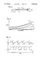
- FIG. 4is a graphical depiction of the major non-fluid forces acting on an actuator of the valve as a function of displacement from the valve seat;
- FIG. 5is a graphical depiction of a timing sequence comparing the timing of an actuation signal applied to an electro-magnet for the invention with the timing of an actuation signal applied to a piezo-electric actuator for the invention.
- a piezo-electrically actuated valve 10 of the inventionincludes a valve housing 12 which is made up of body 14 and cap 16 which define chamber 36.
- the valve 10also includes nozzle type valve seat 18, piezo-electric actuator 20, solenoid magnet 22 and, optionally, an adjusting means 24.
- the body 14defines an inlet passage 26 and an outlet passage 30, with the seat 18 between the two passages.
- the inlet passage 26is for receiving a pressurized flow of fluid, such as air or hydraulic fluid, from a suitable source (not shown) such as a pump, and communicating it to the chamber 36 in which the actuator 20 resides.
- the ends 20A and 20B of the actuator 20are clamped between the cap 16 and the body 14.
- An O-ring 38seals the cap 16 to the body 14 and bolts 40 secure the cap 16 to the body 14.
- Electrical connector 21is secured to the cap 16 so as to provide a fluid tight connection therebetween.
- Wires 17 and 19run from connector 21 to electro-magnet 22 and wires 52 and 54 run from connector 21 to the piezo-electric actuator 20.
- Connector 21has terminals which are electrically connected to the respective wires 17, 19, 52 and 54, to establish an electrical connection between the magnet 22 and actuator 20, and suitable respective power sources 27, 29 outside of the valve 10.
- Such power sourcesare well known and commercially available, for example, from Applied Power Inc., of Butler, Wis. Such power sources may be selected to output either a pulse width modulated signal or a proportional analog voltage signal in any combination, and both sources may be operated at the same time, or not.
- FIG. 1is a schematic representation of a basic valve arrangement incorporating the invention and that the invention could be applied to any of a variety of valves, including those described in U.S. Pat. Nos. 5,328,147 and 4,774,976, which are hereby incorporated by reference, and to any of a variety of piezoelectric actuators including those described in U.S. patent application Ser. No. 08/391,972, entitled “Piezo-Electrically Actuated Valve” and U.S. patent application Ser. No. 08/392,016, entitled “Piezo Composite Sheet Actuated Valve", both referred to above, filed on the same day as this application and commonly assigned to Applied Power Inc., the disclosures of which are also hereby incorporated by reference.
- the actuator 20is a piezo-ceramic monomorph, which as illustrated includes an electrode sheet 48 which is laminated on one of its sides to a layer 50, which is a sheet of piezo-ceramic material.
- An electrically conductive coating 51such as silver oxide, is applied to the surface of sheet 50 which is opposite from electrode 48 and a lead wire 52 (FIGS. 2 and 3) is soldered so as to establish electrical contact with the conductive coating electrode 51.
- a second lead wire 54is soldered to the surface of electrode 48 which is opposite from piezo-ceramic sheet 50 so as to establish electrical contact with the electrode sheet 48.
- An electrical potentialis applied between the wires 52 and 54 so as to excite the piezo-ceramic sheet 50, which would be in the field created between the coated electrode 51 and the sheet electrode 48.
- the piezo-ceramic sheet 50is poled, preferably in the thickness direction, so that when it is excited with an electric field, the actuator 20 bows or cups in the direction indicated by arrow 56 in FIG. 3.
- Such monomorphsare available from EDO Corporation, Acoustics Division, of Salt Lake City, Utah.
- the electrode sheet 48was made of invar metal, and had dimensions of 2" by 1" by approximately 0.008" thick.
- the piezo-ceramic sheetwas EDO Corporation's EC-98 ceramic, which is a lead magnesium niobate composition, and had dimensions of 1.75" by 1" by 0.020" thick.
- the actuator 20Since the actuator 20 is assembled in the housing 12 with the piezo-ceramic sheet side facing the nozzle 18, a small area (for example 0.19" diameter) 58 of the coated electrode 51 is removed at the center of the actuator 20 and the nozzle 18 contacts the actuator 20 within this area. At least the electrode coating 51 must be removed in the area 58 or else, since the electrode 51 is positively charged when the actuator 20 is excited, an electrical short would be created between the electrode coating 51 and the nozzle 18. Alternatively, since the electrode sheet 48 is grounded, as is the nozzle 18, the electrode coating 51 and the piezo-ceramic sheet 50 may be removed in the area 58 and the electrode sheet 48 allowed to contact and seal against the nozzle 18.
- the actuator 20is clamped by the housing 12 along only its end edges 20A and 20B, which are the end edges of the electrode sheet 48.
- the dotted line 64 in FIG. 2identifies the shape defined by the sidewalls of the chamber 36 relative to the actuator 20 and there it can be seen that a space 66 and 68 exists between the respective side edges 20C and 20D of the actuator 20 and the sidewalls 20 of the chamber 36.
- the spaces 66 and 68allow fluid entering the chamber 36 from the inlet passage 26 to flow around the side edges 20C and 20D of the actuator 20 to the far side (or electrode sheet 48 side) of the actuator 20.
- Fis the force
- a 1is the cross-sectional area of the nozzle 18
- P 1is the pressure in the chamber 36
- P 2is the pressure interior of the nozzle 18.
- the adjusting means 24has a shaft 74 which is axially secured to the magnet 22 so as to be rotatable relative thereto and the adjusting means is sealed to the body 14 so as to create a fluid tight connection.
- the adjusting means 24can be screwed into or out of the housing 12 so as to make small adjustments in the axial position of the shaft 74, and when that is done, very small adjustments in the axial position of the magnet 22 are also made relative to the actuator 20.
- the magnet 22is adjusted toward or away from the actuator 20 by the adjusting means 24.
- the adjusting meansneed not be provided as part of the valve, but some other means such as shims, a friction fit, or the type of adjustment described in U.S. Pat. No. 4,774,976 may be provided so that the axial position of the magnet 22 relative to the actuator 20 could be adjusted if necessary so as to provide the desired results in relation to the actuator 20. Alternatively, no adjustment may be necessary, depending on manufacturing tolerances and the application to which the valve is to be applied.
- the axial position of the actuator 20 relative to the seat 18is such as to produce a null condition (i.e., no flow) at relatively low pressure, for example, 20 psig, in the chamber 36.
- a null conditioni.e., no flow
- the pressure in chamber 36may be much higher, for example 200 psig.
- the actuator 20may be excited by a pulse width modulated electrical signal or by a proportional voltage signal.
- the voltages requiredare relatively high. In the actuator described, at a voltage of 500 volts the center displacement (at axis 11 of nozzle 18) is approximately 0.010 inches. Although high voltages are required, the actuator 20 draws current only while it is in motion (typically less than 0.001 sec.) and thus requires less average current than a solenoid for the same duty cycle.
- the actuator 20has a fast response so that a relatively high frequency can be used for a pulse width modulated signal for driving the actuator 20.
- a relatively high frequency for modulating the actuator 20(relative to the frequency which can be used with a solenoid operated valve) is desirable because it results in smoothing of the resulting pressure signal at the control passage 30, i.e. the resulting pressure signal has less "dither" at the higher frequencies. Also, for a given pulse width modulated signal frequency, the pressure control band increases with faster valve actuation.
- magnet 22is provided. Magnet 22 is shown in FIG. 1 as an electromagnet, but could be replaced with a permanent magnet.
- the magnetic field of an electromagnetcan be adjusted by varying the electrical signal applied to the electromagnet by the source 27, thereby allowing an additional means of control of the actuator 20.
- the actuator 20must be magnetically attractable. In the embodiment illustrated and described, this is provided by the electrode sheet 48, since the invar material of the sheet 48 is magnetically attractable.
- a magnetically attractable piece, such as a sheet of iron, steel or a magnet,could also be attached to the actuator 20, for example to the electrode sheet 48, to provide an additional magnetic flux path.
- the magnet 22when energized creates a magnetic field, which is variable according to the electrical signal applied to the magnet coil by source 27.
- the magnetic fieldattracts the actuator 20 toward the magnet 22, particularly when the actuator 20 gets close to the magnet 22.
- an actuator 20can be spaced apart from the magnet 22 such that at some point as actuator 20 approaches its peak displacement from the seat 18, the magnetic field generated by magnet 22 acts together with the piezo-electric force to draw the center of the actuator 20 further away from the seat 18.
- a single power sourcecould be used for both the actuator 20 and the magnet 22, with the actuator 20 and magnet 22 connected in series or in parallel.
- the pulse width modulated signals of the two sourcescould be set to have the same phase and duty cycle, or the phase relationship between the two signals and their duty cycles may be varied in any way desired to vary the results achieved. For example, referring to FIG.
- the magnet 22may be operated separately and apart from electrically actuating the actuator 20 to draw the actuator 20 away from the seat 18 by itself.
- the actuator 20can be moved away from the seat 18 by only the electrical actuation provided by source 29, without assistance from the magnet 22.
- FIG. 4illustrates a graphical depiction of the major forces acting on the actuator 20 as a function of the center displacement of the actuator 20 from the seat 18 when the actuator is both magnetically and electrically actuated (i.e., when both sources 27 and 29 are operated in unison to move the actuator 20).
- the spring force due to the resiliency of the actuator 20which tends to close the actuator 20 against seat 18
- the piezo forcewhich is the force induced by subjecting layer 50 of actuator 20 to an electric field via leads 52 and 54, which tends to open the seat 18
- the magnet force introduced by magnet 22, which also tends to open the seatare three major non-fluid forces: the spring force due to the resiliency of the actuator 20, which tends to close the actuator 20 against seat 18; the piezo force, which is the force induced by subjecting layer 50 of actuator 20 to an electric field via leads 52 and 54, which tends to open the seat 18; and the magnet force introduced by magnet 22, which also tends to open the seat.
- the spring forceis depicted as a line 101 of constant slope
- the piezo forceis depicted as a constant force by line 103
- the magnet forceis depicted by curve 105, the slope of which increases with increasing displacement, i.e., as the actuator 20 approaches the magnet 22.
- Curve 107represents the sum of the piezo force and the magnet force, both of which act in the same direction, tending to displace the actuator 20 away from the nozzle 18.
- the force due to fluid pressure acting on the actuator 20, which tends to close the actuator 20 against the nozzle 18,is depicted by line 109.
- the axial position of the magnet 22 relative to the actuator 20 and also the strength of the magnetic field produced by the magnet 22are adjustable. As such, the spacing and magnetic field strength may be adjusted so that when the magnet 22 is energized and the actuator 20 is energized, the actuator 20 latches up against the bottom surface of the magnet 22.
- This methoddoes not use the inertia force generated when the actuator 20 moves toward the magnet 22 from the seat 20. However, the inertia force, which is in the same direction as the piezo force and the magnet force, gives an added measure of protection that the actuator 20 will latch against the magnet 22.
- the spacing between the magnet 22 and the actuator 20 and the magnetic field strengthmust be adjusted to not only insure latching, but should also be adjusted to insure that when the actuator 20 is de-energized, the spring force is greater than the magnet force so that actuator 20 will unlatch from the magnet 22, so that the valve will close.
- the spacing of the magnet 22 from the actuator 20 and the magnetic field strengthcan also be adjusted (or designed in a production unit) so as to more fully utilize the inertia force generated when the actuator 20 moves in the direction from the seat 18 toward the magnet 22.
- the dynamic inertia forceis used to help further open the valve.
- latchingneed not occur, and not even necessarily contact need occur, between the actuator 20 and the magnet 22.
- Thisis a ballistic system, the actuator 20 being essentially thrown up by the inertia force into the field of influence of the magnetic field so that the magnetic field can contribute to the peak displacement of the actuator 20 from the seat 18.
- the magnetic fieldmust be designed to be less than the spring force at the maximum deflection point so that the valve will close when the piezo force is relieved. Also, in either method, mass could be added to the actuator 20 so as to increase the inertia force, if desired.
- the magnet 22be an electromagnet.
- the magnet 22could be a permanent magnet, or could utilize residual magnetism to establish the magnetic field which acts on the actuator 20. Also, once the desired spacing between the magnet 22 and actuator 20 has been determined by trial and error for a particular application, it may not be necessary to adjust the magnet position since the desired spacing can be controlled by dimensional tolerances.
- the inventionprovides a piezo-electrically actuated fluid control valve in which the utilization of magnetic forces provides greater valve deflection for a given input voltage, or which can provide the same deflection for significantly less voltage.
- the resultis improved valve performance, or lower power required to drive the valve, and also potentially lower cost of the electronic control circuits used to drive the actuator 20.
- the actuatoris smaller and lighter than prior solenoid operated or piezo-operated actuators, and as a result has a fast frequency response, so that it may be used to control relatively high pressures over a relatively wider pressure control band and at a higher frequency for a lower pressure dither amplitude.
Landscapes
- Engineering & Computer Science (AREA)
- General Engineering & Computer Science (AREA)
- Mechanical Engineering (AREA)
- Physics & Mathematics (AREA)
- Electromagnetism (AREA)
- Chemical & Material Sciences (AREA)
- Combustion & Propulsion (AREA)
- Electrically Driven Valve-Operating Means (AREA)
Abstract
Description
F=A.sub.1 (P.sub.1 -P.sub.2)
Claims (16)
Priority Applications (5)
| Application Number | Priority Date | Filing Date | Title |
|---|---|---|---|
| US08/391,887US5593134A (en) | 1995-02-21 | 1995-02-21 | Magnetically assisted piezo-electric valve actuator |
| AU48691/96AAU4869196A (en) | 1995-02-21 | 1996-02-20 | Piezo-electrically actuated valve |
| PCT/US1996/002235WO1996026378A1 (en) | 1995-02-21 | 1996-02-20 | Magnetically assisted piezo-electric valve actuator |
| PCT/US1996/002201WO1996026377A1 (en) | 1995-02-21 | 1996-02-20 | Piezo-electrically actuated valve |
| AU49281/96AAU4928196A (en) | 1995-02-21 | 1996-02-20 | Magnetically assisted piezo-electric valve actuator |
Applications Claiming Priority (1)
| Application Number | Priority Date | Filing Date | Title |
|---|---|---|---|
| US08/391,887US5593134A (en) | 1995-02-21 | 1995-02-21 | Magnetically assisted piezo-electric valve actuator |
Publications (1)
| Publication Number | Publication Date |
|---|---|
| US5593134Atrue US5593134A (en) | 1997-01-14 |
Family
ID=23548368
Family Applications (1)
| Application Number | Title | Priority Date | Filing Date |
|---|---|---|---|
| US08/391,887Expired - Fee RelatedUS5593134A (en) | 1995-02-21 | 1995-02-21 | Magnetically assisted piezo-electric valve actuator |
Country Status (1)
| Country | Link |
|---|---|
| US (1) | US5593134A (en) |
Cited By (55)
| Publication number | Priority date | Publication date | Assignee | Title |
|---|---|---|---|---|
| US5810255A (en)* | 1995-08-29 | 1998-09-22 | Robert Bosch Gmbh | Clamping device for a piesoelectric actuator of a fuel injection valve for internal combustion engines |
| WO1998053233A1 (en)* | 1997-05-19 | 1998-11-26 | Q-Core Ltd. | Magnetic flow controller |
| GB2329004A (en)* | 1997-05-19 | 1999-03-10 | Core Limited Q | Magnetic flow controller |
| US5967488A (en)* | 1998-05-29 | 1999-10-19 | Redlich; Robert Walter | Electrically actuated reed valve |
| US6047945A (en)* | 1996-11-27 | 2000-04-11 | Nass Magnet Gmbh | Electromagnetic valve construction |
| US6062256A (en)* | 1997-02-11 | 2000-05-16 | Engineering Measurements Company | Micro mass flow control apparatus and method |
| US6091314A (en)* | 1998-06-05 | 2000-07-18 | Siemens Automotive Corporation | Piezoelectric booster for an electromagnetic actuator |
| US6102365A (en)* | 1998-03-30 | 2000-08-15 | Siemens Aktiengesellschaft | Actuating drive for a pneumatic valve of an insertion head for electrical components |
| US6116863A (en)* | 1997-05-30 | 2000-09-12 | University Of Cincinnati | Electromagnetically driven microactuated device and method of making the same |
| EP0915277A3 (en)* | 1997-10-15 | 2000-11-15 | Bürkert Werke GmbH & Co. | Piezo-electric valve |
| US6230501B1 (en) | 1994-04-14 | 2001-05-15 | Promxd Technology, Inc. | Ergonomic systems and methods providing intelligent adaptive surfaces and temperature control |
| US6302495B1 (en)* | 1999-06-04 | 2001-10-16 | Ge Harris Railway Electronics, Llc | Railway car braking system including piezoelectric pilot valve and associated methods |
| WO2001088421A1 (en)* | 2000-05-16 | 2001-11-22 | Robert Bosch Gmbh | Fluid control valve |
| WO2001095829A2 (en) | 2000-06-15 | 2001-12-20 | Innoventions Inc. | Intravesicular device |
| US6350537B1 (en) | 1998-12-18 | 2002-02-26 | Aer Energy Resources, Inc. | Load responsive air door for an electrochemical cell |
| US20030038608A1 (en)* | 2000-03-15 | 2003-02-27 | Alexander Meisselbach | Device for controlling a hydraulic actuator |
| US6586889B1 (en) | 2000-06-21 | 2003-07-01 | Si Diamond Technology, Inc. | MEMS field emission device |
| US20030172975A1 (en)* | 2002-03-15 | 2003-09-18 | Coventor, Inc. | Latching micro-regulator |
| US6685164B1 (en)* | 2000-09-11 | 2004-02-03 | Hamai Industries Limited | Control valve and diaphragm for use in the control valve |
| US20050146248A1 (en)* | 2003-11-20 | 2005-07-07 | Moler Jeffery B. | Integral thermal compensation for an electro-mechanical actuator |
| US20050221147A1 (en)* | 2004-03-31 | 2005-10-06 | Canon Kabushiki Kaisha | Valve having valve element displaced by at least one of a movement of a diaphragm and a movement of an actuator, and fuel cell using the valve |
| EP1619385A1 (en)* | 2004-07-23 | 2006-01-25 | Dualon International Holding SA | Actuator for a fuel injection system |
| US20060145110A1 (en)* | 2005-01-06 | 2006-07-06 | Tzu-Yu Wang | Microfluidic modulating valve |
| US20070090321A1 (en)* | 2005-10-26 | 2007-04-26 | Toralf Bork | Dynamic hermetic barrier for use with implantable infusion pumps |
| US7219449B1 (en) | 1999-05-03 | 2007-05-22 | Promdx Technology, Inc. | Adaptively controlled footwear |
| US20070269324A1 (en)* | 2004-11-24 | 2007-11-22 | O-Core Ltd. | Finger-Type Peristaltic Pump |
| US20080041604A1 (en)* | 2004-07-02 | 2008-02-21 | Hermann Sauer | Tool with an Oscillating Head |
| US20080095649A1 (en)* | 2002-11-14 | 2008-04-24 | Zvi Ben-Shalom | Peristaltic Pump |
| US20080236584A1 (en)* | 2005-04-01 | 2008-10-02 | Ric Investments, Llc | Gas Conserving Device |
| US20090140184A1 (en)* | 2005-10-26 | 2009-06-04 | Rocco Crivelli | Flow Rate Accuracy of a Fluidic Delivery System |
| US20090140185A1 (en)* | 2005-10-26 | 2009-06-04 | Rocco Crivelli | Flow Rate Accuracy of a Fluidic Delivery System |
| US20090221964A1 (en)* | 2004-11-24 | 2009-09-03 | Q-Core Medical Ltd | Peristaltic infusion pump with locking mechanism |
| US20090240201A1 (en)* | 2006-11-13 | 2009-09-24 | Q-Core Medical Ltd | Magnetically balanced finger-type peristaltic pump |
| US20100036322A1 (en)* | 2006-11-13 | 2010-02-11 | Q-Core Medical Ltd. | Anti-free flow mechanism |
| US20100163768A1 (en)* | 2007-06-20 | 2010-07-01 | So Elektronik Ab | Electromechanical Vlave |
| US20110127459A1 (en)* | 2008-06-27 | 2011-06-02 | Murata Manufacturing Co., Ltd. | Microvalve and valve seat member |
| US20110152831A1 (en)* | 2009-12-22 | 2011-06-23 | Q-Core Medical Ltd | Peristaltic Pump with Linear Flow Control |
| US20110152772A1 (en)* | 2009-12-22 | 2011-06-23 | Q-Core Medical Ltd | Peristaltic Pump with Bi-Directional Pressure Sensor |
| US8337168B2 (en) | 2006-11-13 | 2012-12-25 | Q-Core Medical Ltd. | Finger-type peristaltic pump comprising a ribbed anvil |
| US20140366952A1 (en)* | 2009-10-15 | 2014-12-18 | Pivotal Systems Corporation | Method and apparatus for gas flow control |
| US9155871B2 (en) | 2010-11-19 | 2015-10-13 | C. Miethke Gmbh & Co Kg | Electrically operable, in one possible embodiment programmable hydrocephalus valve |
| WO2015158424A1 (en)* | 2014-04-16 | 2015-10-22 | Iro Aktiebolag | Air jet weaving machine comprising electromagnetic valve |
| US20160131268A1 (en)* | 2014-11-07 | 2016-05-12 | Buerkert Werke Gmbh | Seat valve |
| US9400004B2 (en) | 2010-11-29 | 2016-07-26 | Pivotal Systems Corporation | Transient measurements of mass flow controllers |
| US20160228889A1 (en)* | 2015-02-10 | 2016-08-11 | Tokkyokiki Corporation | Fluid Servo Valve and Fluid Servo Apparatus |
| US9457158B2 (en) | 2010-04-12 | 2016-10-04 | Q-Core Medical Ltd. | Air trap for intravenous pump |
| US9534451B2 (en) | 1999-02-17 | 2017-01-03 | Den-Con Electronics, Inc. | Oilfield equipment identification method and apparatus |
| US9674811B2 (en) | 2011-01-16 | 2017-06-06 | Q-Core Medical Ltd. | Methods, apparatus and systems for medical device communication, control and localization |
| US9726167B2 (en) | 2011-06-27 | 2017-08-08 | Q-Core Medical Ltd. | Methods, circuits, devices, apparatuses, encasements and systems for identifying if a medical infusion system is decalibrated |
| US9855110B2 (en) | 2013-02-05 | 2018-01-02 | Q-Core Medical Ltd. | Methods, apparatus and systems for operating a medical device including an accelerometer |
| US20180361405A1 (en)* | 2017-06-20 | 2018-12-20 | Progressive Grower Technologies, Inc. | Electrostatic spraying system for agriculture |
| US10205082B2 (en) | 2016-04-20 | 2019-02-12 | Honeywell International Inc. | Constrained piezo-electric element to improve drive capability |
| US10401202B2 (en) | 2015-07-10 | 2019-09-03 | Pivotal Systems Corporation | Method and apparatus for gas flow control |
| US20220120356A1 (en)* | 2020-10-19 | 2022-04-21 | Buerkert Werke Gmbh & Co. Kg | Valve having a valve body |
| US11679189B2 (en) | 2019-11-18 | 2023-06-20 | Eitan Medical Ltd. | Fast test for medical pump |
Citations (71)
| Publication number | Priority date | Publication date | Assignee | Title |
|---|---|---|---|---|
| US2596409A (en)* | 1947-03-14 | 1952-05-13 | A P Controls Corp | Solenoid gas valve |
| US2928409A (en)* | 1955-01-31 | 1960-03-15 | Textron Inc | Non-magnetic electro hydraulic transfer valve |
| US3063422A (en)* | 1960-06-13 | 1962-11-13 | Joel H Gregowski | Electromechanical device |
| US3096269A (en)* | 1961-05-23 | 1963-07-02 | Halbach Klaus | Counterrotating plasma device |
| US3152612A (en)* | 1956-09-28 | 1964-10-13 | Gen Electric | Piezoelectric crystal transducer for controlling fluid flow |
| US3465732A (en)* | 1967-10-19 | 1969-09-09 | Physics Int Co | Piezoelectric control valve |
| US3524474A (en)* | 1967-10-12 | 1970-08-18 | Delta Hydraulics Co | Servo-valve with ceramic force motor |
| US3676722A (en)* | 1969-10-06 | 1972-07-11 | Motorola Inc | Structure for bimorph or monomorph benders |
| US3753426A (en)* | 1971-04-21 | 1973-08-21 | Physics Int Co | Balanced pressure fuel valve |
| US3803424A (en)* | 1972-05-08 | 1974-04-09 | Physics Int Co | Piezoelectric pump system |
| US3927652A (en)* | 1974-06-21 | 1975-12-23 | Physics Int Co | Fuel injection system for internal combustion engines |
| US4195811A (en)* | 1977-08-22 | 1980-04-01 | EMX Controls Inc. | Electronic valve control means |
| US4219755A (en)* | 1977-03-18 | 1980-08-26 | Physics International Company | Electromotive actuator |
| US4227111A (en)* | 1979-03-28 | 1980-10-07 | The United States Of America As Represented By The Secretary Of The Navy | Flexible piezoelectric composite transducers |
| US4271989A (en)* | 1979-03-27 | 1981-06-09 | Physics International Company | Micro-metering system |
| US4298181A (en)* | 1979-07-09 | 1981-11-03 | Emx Controls, Inc. | Electronic actuated bleed valve |
| US4318023A (en)* | 1980-02-21 | 1982-03-02 | Physics International Company | Sagittally amplified piezoelectric actuator |
| US4324268A (en)* | 1979-08-24 | 1982-04-13 | Jacobson Avram A | Automatic flood control valve |
| JPS5828079A (en)* | 1981-08-13 | 1983-02-18 | Matsushita Electric Ind Co Ltd | Gas control valve |
| US4412148A (en)* | 1981-04-24 | 1983-10-25 | The United States Of America As Represented By The Secretary Of The Navy | PZT Composite and a fabrication method thereof |
| US4460840A (en)* | 1981-04-28 | 1984-07-17 | Daimler-Benz Aktiengesellschaft | Temperature compensated piezoelectric actuator arrangement |
| US4466390A (en)* | 1981-09-09 | 1984-08-21 | Robert Bosch Gmbh | Electro-hydraulic valve control system for internal combustion engine valves |
| EP0117195A1 (en)* | 1983-02-14 | 1984-08-29 | Mecilec S.A. | Electromagnetic valves with piezoelectric actuating means |
| US4492360A (en)* | 1982-06-07 | 1985-01-08 | The Lee Company | Piezoelectric valve |
| US4535810A (en)* | 1984-03-27 | 1985-08-20 | Dynamic Valves, Inc. | Electrically controlled valves |
| US4550744A (en)* | 1982-11-16 | 1985-11-05 | Nippon Soken, Inc. | Piezoelectric hydraulic control valve |
| GB2171498A (en)* | 1985-01-18 | 1986-08-28 | Diesel Kiki Co | High speed electromagnetic valve |
| US4610426A (en)* | 1984-07-10 | 1986-09-09 | Atlas Fahrzeugtechnik Gmbh | Piezoceramic valve plate for a low-pressure injection valve and process for the production thereof |
| US4624796A (en)* | 1985-06-07 | 1986-11-25 | Celanese Corporation | Piezoelectric filler and flexible piezoelectric composites |
| US4629926A (en)* | 1985-10-21 | 1986-12-16 | Kiwi Coders Corporation | Mounting for piezoelectric bender of fluid control device |
| WO1986007429A1 (en)* | 1985-06-11 | 1986-12-18 | Arthur D. Little, Inc. | Apparatus for electrical control of rate of fluid flow |
| US4643155A (en)* | 1984-10-05 | 1987-02-17 | Olin Corporation | Variable stroke, electronically controlled fuel injection control system |
| US4688536A (en)* | 1985-06-28 | 1987-08-25 | Toyota Jidosha Kabushiki Kaisha | Drive circuit for an electrostrictive actuator in a fuel injection valve |
| US4690465A (en)* | 1985-05-22 | 1987-09-01 | Nippon Soken, Inc. | Antiskid hydraulic pressure modulator for vehicle hydraulic braking system |
| US4700971A (en)* | 1984-05-21 | 1987-10-20 | Kabushiki Kaisha Toyota Chuo Kenkyusho | Adjustable hydropneumatic active suspension apparatus |
| US4705059A (en)* | 1985-06-10 | 1987-11-10 | Centre Technique Des Industries Mecaniques | Electrofluidic transducer of the nozzle/plate type and hydraulic servo-valve equipped with such a transducer |
| US4724801A (en)* | 1987-01-15 | 1988-02-16 | Olin Corporation | Hydraulic valve-operating system for internal combustion engines |
| US4774976A (en)* | 1987-09-23 | 1988-10-04 | Applied Power Inc. | Modulating hydraulic pressure control valve and assembly method therefor |
| US4793313A (en)* | 1986-04-10 | 1988-12-27 | Robert Bosch Gmbh | Fuel injection apparatus for internal combustion engines |
| US4862029A (en)* | 1987-02-11 | 1989-08-29 | Tosoh Corporation | Actuator |
| US4877296A (en)* | 1987-07-18 | 1989-10-31 | Daimler-Benz Aktiengesellschaft | Antilocking system for a road vehicle |
| US4892328A (en)* | 1988-05-27 | 1990-01-09 | Aura Systems, Inc. | Electromagnetic strut assembly |
| US4912343A (en)* | 1988-08-31 | 1990-03-27 | Aura Systems, Inc. | Electromagnetic actuator |
| US4969662A (en)* | 1989-06-08 | 1990-11-13 | Aura Systems, Inc. | Active damping system for an automobile suspension |
| US4999819A (en)* | 1990-04-18 | 1991-03-12 | The Pennsylvania Research Corporation | Transformed stress direction acoustic transducer |
| US5021957A (en)* | 1988-11-10 | 1991-06-04 | Nippon Soken, Inc. | Brake control apparatus in diagonal braking pressure supply system for use in motor vehicles |
| US5099158A (en)* | 1989-03-07 | 1992-03-24 | Aura Systems, Inc. | Electromagnetic actuator |
| US5100100A (en)* | 1990-09-12 | 1992-03-31 | Mks Instruments, Inc. | Fluid control and shut off valve |
| US5135070A (en)* | 1991-07-30 | 1992-08-04 | Aura Systems, Inc. | Active hydraulic pressure control |
| US5159225A (en)* | 1991-10-18 | 1992-10-27 | Aura Systems, Inc. | Piezoelectric actuator |
| US5162767A (en)* | 1991-04-03 | 1992-11-10 | Aura Systems, Inc. | High efficiency solenoid |
| US5173673A (en)* | 1990-06-20 | 1992-12-22 | Ericson Manufacturing Company | Magnetic solenoid resettable ground fault circuit interrupter |
| US5175465A (en)* | 1991-10-18 | 1992-12-29 | Aura Systems, Inc. | Piezoelectric and electrostrictive actuators |
| US5187398A (en)* | 1988-08-31 | 1993-02-16 | Aura Systems, Inc. | Electromagnetic actuator |
| US5191687A (en)* | 1990-09-28 | 1993-03-09 | Caterpillar Inc. | Process for making piezoelectric stacks |
| US5203537A (en)* | 1992-03-09 | 1993-04-20 | Teledyne Industries, Inc. | Piezoceramic valve actuator sandwich assembly and valve incorporating such an assembly |
| US5207737A (en)* | 1992-02-27 | 1993-05-04 | Landis & Gyr Powers, Inc. | Analog output electro-pneumatic transducer |
| US5222714A (en)* | 1992-10-05 | 1993-06-29 | Aura Systems, Inc. | Electromagnetically actuated valve |
| US5224510A (en)* | 1989-11-08 | 1993-07-06 | Ciba-Geigy Corporation | Valve |
| US5237968A (en)* | 1992-11-04 | 1993-08-24 | Caterpillar Inc. | Apparatus for adjustably controlling valve movement and fuel injection |
| GB2264998A (en)* | 1992-03-09 | 1993-09-15 | Nippon Denso Co | Electro-magnetic control valve |
| US5267589A (en)* | 1993-04-05 | 1993-12-07 | Ford Motor Company | Piezoelectric pressure control valve |
| US5276657A (en)* | 1992-02-12 | 1994-01-04 | The Pennsylvania Research Corporation | Metal-electroactive ceramic composite actuators |
| WO1994000696A1 (en)* | 1992-06-26 | 1994-01-06 | Robert Bosch Gmbh | Microvalve |
| US5285995A (en)* | 1992-05-14 | 1994-02-15 | Aura Systems, Inc. | Optical table active leveling and vibration cancellation system |
| US5328147A (en)* | 1993-06-17 | 1994-07-12 | Applied Power Inc. | Two stage pressure control valve |
| US5340081A (en)* | 1993-06-07 | 1994-08-23 | The United States Of America As Represented By The United States Department Of Energy | Means for positively seating a piezoceramic element in a piezoelectric valve during inlet gas injection |
| US5374029A (en)* | 1992-06-26 | 1994-12-20 | Wright Components, Inc. | Solenoid flow control valve and frictionless plunger assembly |
| GB2280999A (en)* | 1993-08-09 | 1995-02-15 | Motorola Inc | Transconductance amplifiers |
| US5452878A (en)* | 1991-06-18 | 1995-09-26 | Danfoss A/S | Miniature actuating device |
| US5470095A (en)* | 1994-07-20 | 1995-11-28 | Bridges; James E. | Transportable golf bag |
- 1995
- 1995-02-21USUS08/391,887patent/US5593134A/ennot_activeExpired - Fee Related
Patent Citations (72)
| Publication number | Priority date | Publication date | Assignee | Title |
|---|---|---|---|---|
| US2596409A (en)* | 1947-03-14 | 1952-05-13 | A P Controls Corp | Solenoid gas valve |
| US2928409A (en)* | 1955-01-31 | 1960-03-15 | Textron Inc | Non-magnetic electro hydraulic transfer valve |
| US3152612A (en)* | 1956-09-28 | 1964-10-13 | Gen Electric | Piezoelectric crystal transducer for controlling fluid flow |
| US3063422A (en)* | 1960-06-13 | 1962-11-13 | Joel H Gregowski | Electromechanical device |
| US3096269A (en)* | 1961-05-23 | 1963-07-02 | Halbach Klaus | Counterrotating plasma device |
| US3524474A (en)* | 1967-10-12 | 1970-08-18 | Delta Hydraulics Co | Servo-valve with ceramic force motor |
| US3465732A (en)* | 1967-10-19 | 1969-09-09 | Physics Int Co | Piezoelectric control valve |
| US3676722A (en)* | 1969-10-06 | 1972-07-11 | Motorola Inc | Structure for bimorph or monomorph benders |
| US3753426A (en)* | 1971-04-21 | 1973-08-21 | Physics Int Co | Balanced pressure fuel valve |
| US3803424A (en)* | 1972-05-08 | 1974-04-09 | Physics Int Co | Piezoelectric pump system |
| US3927652A (en)* | 1974-06-21 | 1975-12-23 | Physics Int Co | Fuel injection system for internal combustion engines |
| US4098560A (en)* | 1974-06-21 | 1978-07-04 | Physics International Company | Fuel injection pumps for internal combustion engines |
| US4219755A (en)* | 1977-03-18 | 1980-08-26 | Physics International Company | Electromotive actuator |
| US4195811A (en)* | 1977-08-22 | 1980-04-01 | EMX Controls Inc. | Electronic valve control means |
| US4271989A (en)* | 1979-03-27 | 1981-06-09 | Physics International Company | Micro-metering system |
| US4227111A (en)* | 1979-03-28 | 1980-10-07 | The United States Of America As Represented By The Secretary Of The Navy | Flexible piezoelectric composite transducers |
| US4298181A (en)* | 1979-07-09 | 1981-11-03 | Emx Controls, Inc. | Electronic actuated bleed valve |
| US4324268A (en)* | 1979-08-24 | 1982-04-13 | Jacobson Avram A | Automatic flood control valve |
| US4318023A (en)* | 1980-02-21 | 1982-03-02 | Physics International Company | Sagittally amplified piezoelectric actuator |
| US4412148A (en)* | 1981-04-24 | 1983-10-25 | The United States Of America As Represented By The Secretary Of The Navy | PZT Composite and a fabrication method thereof |
| US4460840A (en)* | 1981-04-28 | 1984-07-17 | Daimler-Benz Aktiengesellschaft | Temperature compensated piezoelectric actuator arrangement |
| JPS5828079A (en)* | 1981-08-13 | 1983-02-18 | Matsushita Electric Ind Co Ltd | Gas control valve |
| US4466390A (en)* | 1981-09-09 | 1984-08-21 | Robert Bosch Gmbh | Electro-hydraulic valve control system for internal combustion engine valves |
| US4492360A (en)* | 1982-06-07 | 1985-01-08 | The Lee Company | Piezoelectric valve |
| US4550744A (en)* | 1982-11-16 | 1985-11-05 | Nippon Soken, Inc. | Piezoelectric hydraulic control valve |
| EP0117195A1 (en)* | 1983-02-14 | 1984-08-29 | Mecilec S.A. | Electromagnetic valves with piezoelectric actuating means |
| US4535810A (en)* | 1984-03-27 | 1985-08-20 | Dynamic Valves, Inc. | Electrically controlled valves |
| US4700971A (en)* | 1984-05-21 | 1987-10-20 | Kabushiki Kaisha Toyota Chuo Kenkyusho | Adjustable hydropneumatic active suspension apparatus |
| US4610426A (en)* | 1984-07-10 | 1986-09-09 | Atlas Fahrzeugtechnik Gmbh | Piezoceramic valve plate for a low-pressure injection valve and process for the production thereof |
| US4643155A (en)* | 1984-10-05 | 1987-02-17 | Olin Corporation | Variable stroke, electronically controlled fuel injection control system |
| GB2171498A (en)* | 1985-01-18 | 1986-08-28 | Diesel Kiki Co | High speed electromagnetic valve |
| US4690465A (en)* | 1985-05-22 | 1987-09-01 | Nippon Soken, Inc. | Antiskid hydraulic pressure modulator for vehicle hydraulic braking system |
| US4624796A (en)* | 1985-06-07 | 1986-11-25 | Celanese Corporation | Piezoelectric filler and flexible piezoelectric composites |
| US4705059A (en)* | 1985-06-10 | 1987-11-10 | Centre Technique Des Industries Mecaniques | Electrofluidic transducer of the nozzle/plate type and hydraulic servo-valve equipped with such a transducer |
| WO1986007429A1 (en)* | 1985-06-11 | 1986-12-18 | Arthur D. Little, Inc. | Apparatus for electrical control of rate of fluid flow |
| US4688536A (en)* | 1985-06-28 | 1987-08-25 | Toyota Jidosha Kabushiki Kaisha | Drive circuit for an electrostrictive actuator in a fuel injection valve |
| US4629926A (en)* | 1985-10-21 | 1986-12-16 | Kiwi Coders Corporation | Mounting for piezoelectric bender of fluid control device |
| US4793313A (en)* | 1986-04-10 | 1988-12-27 | Robert Bosch Gmbh | Fuel injection apparatus for internal combustion engines |
| US4724801A (en)* | 1987-01-15 | 1988-02-16 | Olin Corporation | Hydraulic valve-operating system for internal combustion engines |
| US4862029A (en)* | 1987-02-11 | 1989-08-29 | Tosoh Corporation | Actuator |
| US4877296A (en)* | 1987-07-18 | 1989-10-31 | Daimler-Benz Aktiengesellschaft | Antilocking system for a road vehicle |
| US4774976A (en)* | 1987-09-23 | 1988-10-04 | Applied Power Inc. | Modulating hydraulic pressure control valve and assembly method therefor |
| US4892328A (en)* | 1988-05-27 | 1990-01-09 | Aura Systems, Inc. | Electromagnetic strut assembly |
| US4912343A (en)* | 1988-08-31 | 1990-03-27 | Aura Systems, Inc. | Electromagnetic actuator |
| US5187398A (en)* | 1988-08-31 | 1993-02-16 | Aura Systems, Inc. | Electromagnetic actuator |
| US5021957A (en)* | 1988-11-10 | 1991-06-04 | Nippon Soken, Inc. | Brake control apparatus in diagonal braking pressure supply system for use in motor vehicles |
| US5099158A (en)* | 1989-03-07 | 1992-03-24 | Aura Systems, Inc. | Electromagnetic actuator |
| US4969662A (en)* | 1989-06-08 | 1990-11-13 | Aura Systems, Inc. | Active damping system for an automobile suspension |
| US5224510A (en)* | 1989-11-08 | 1993-07-06 | Ciba-Geigy Corporation | Valve |
| US4999819A (en)* | 1990-04-18 | 1991-03-12 | The Pennsylvania Research Corporation | Transformed stress direction acoustic transducer |
| US5173673A (en)* | 1990-06-20 | 1992-12-22 | Ericson Manufacturing Company | Magnetic solenoid resettable ground fault circuit interrupter |
| US5100100A (en)* | 1990-09-12 | 1992-03-31 | Mks Instruments, Inc. | Fluid control and shut off valve |
| US5191687A (en)* | 1990-09-28 | 1993-03-09 | Caterpillar Inc. | Process for making piezoelectric stacks |
| US5162767A (en)* | 1991-04-03 | 1992-11-10 | Aura Systems, Inc. | High efficiency solenoid |
| US5452878A (en)* | 1991-06-18 | 1995-09-26 | Danfoss A/S | Miniature actuating device |
| US5135070A (en)* | 1991-07-30 | 1992-08-04 | Aura Systems, Inc. | Active hydraulic pressure control |
| US5159225A (en)* | 1991-10-18 | 1992-10-27 | Aura Systems, Inc. | Piezoelectric actuator |
| US5175465A (en)* | 1991-10-18 | 1992-12-29 | Aura Systems, Inc. | Piezoelectric and electrostrictive actuators |
| US5276657A (en)* | 1992-02-12 | 1994-01-04 | The Pennsylvania Research Corporation | Metal-electroactive ceramic composite actuators |
| US5207737A (en)* | 1992-02-27 | 1993-05-04 | Landis & Gyr Powers, Inc. | Analog output electro-pneumatic transducer |
| GB2264998A (en)* | 1992-03-09 | 1993-09-15 | Nippon Denso Co | Electro-magnetic control valve |
| US5203537A (en)* | 1992-03-09 | 1993-04-20 | Teledyne Industries, Inc. | Piezoceramic valve actuator sandwich assembly and valve incorporating such an assembly |
| US5285995A (en)* | 1992-05-14 | 1994-02-15 | Aura Systems, Inc. | Optical table active leveling and vibration cancellation system |
| WO1994000696A1 (en)* | 1992-06-26 | 1994-01-06 | Robert Bosch Gmbh | Microvalve |
| US5374029A (en)* | 1992-06-26 | 1994-12-20 | Wright Components, Inc. | Solenoid flow control valve and frictionless plunger assembly |
| US5222714A (en)* | 1992-10-05 | 1993-06-29 | Aura Systems, Inc. | Electromagnetically actuated valve |
| US5237968A (en)* | 1992-11-04 | 1993-08-24 | Caterpillar Inc. | Apparatus for adjustably controlling valve movement and fuel injection |
| US5267589A (en)* | 1993-04-05 | 1993-12-07 | Ford Motor Company | Piezoelectric pressure control valve |
| US5340081A (en)* | 1993-06-07 | 1994-08-23 | The United States Of America As Represented By The United States Department Of Energy | Means for positively seating a piezoceramic element in a piezoelectric valve during inlet gas injection |
| US5328147A (en)* | 1993-06-17 | 1994-07-12 | Applied Power Inc. | Two stage pressure control valve |
| GB2280999A (en)* | 1993-08-09 | 1995-02-15 | Motorola Inc | Transconductance amplifiers |
| US5470095A (en)* | 1994-07-20 | 1995-11-28 | Bridges; James E. | Transportable golf bag |
Non-Patent Citations (4)
| Title |
|---|
| Applicant Exhibit 1, 1 page flyer of Edo Western Corp., Salt Lake City, Utah, entitled Piezo Ceramic Monomorph and identified at the bottom by EWC 01985 7512, admitted prior art (No Date).* |
| Applicant s Exhibit 2, brochure entitled EDO Corporation Acoustics Division Ceramic Operations Piezoelectric Ceramics, Material Specifications Typical Applications of EDO Corporation Acoustics Division Ceramic Operations, Salt Lake City, Utah, admitted prior art (No Date).* |
| Applicant'Exhibit 1, 1 page flyer of Edo Western Corp., Salt Lake City, Utah, entitled "Piezo-Ceramic Monomorph" and identified at the bottom by EWC 01985 7512, admitted prior art (No Date). |
| Applicant's Exhibit 2, brochure entitled "EDO Corporation Acoustics Division Ceramic Operations Piezoelectric Ceramics, Material Specifications Typical Applications" of EDO Corporation Acoustics Division Ceramic Operations, Salt Lake City, Utah, admitted prior art (No Date). |
Cited By (110)
| Publication number | Priority date | Publication date | Assignee | Title |
|---|---|---|---|---|
| US6230501B1 (en) | 1994-04-14 | 2001-05-15 | Promxd Technology, Inc. | Ergonomic systems and methods providing intelligent adaptive surfaces and temperature control |
| US5810255A (en)* | 1995-08-29 | 1998-09-22 | Robert Bosch Gmbh | Clamping device for a piesoelectric actuator of a fuel injection valve for internal combustion engines |
| US6047945A (en)* | 1996-11-27 | 2000-04-11 | Nass Magnet Gmbh | Electromagnetic valve construction |
| US6230731B1 (en) | 1997-02-11 | 2001-05-15 | Engineering Measurements Company | Valve closure seating method and apparatus |
| US6062256A (en)* | 1997-02-11 | 2000-05-16 | Engineering Measurements Company | Micro mass flow control apparatus and method |
| US6095175A (en)* | 1997-02-11 | 2000-08-01 | Engineering Measurements Company | Clad piezoelectric valve actuator and application of same in controlling highly reactive and corrosive gases |
| AU731145B2 (en)* | 1997-05-19 | 2001-03-22 | Q-Core Ltd. | Magnetic flow controller |
| WO1998053233A1 (en)* | 1997-05-19 | 1998-11-26 | Q-Core Ltd. | Magnetic flow controller |
| GB2329004A (en)* | 1997-05-19 | 1999-03-10 | Core Limited Q | Magnetic flow controller |
| US5996964A (en)* | 1997-05-19 | 1999-12-07 | Q-Core Ltd. | Magnetic flow controller |
| US6116863A (en)* | 1997-05-30 | 2000-09-12 | University Of Cincinnati | Electromagnetically driven microactuated device and method of making the same |
| EP0915277A3 (en)* | 1997-10-15 | 2000-11-15 | Bürkert Werke GmbH & Co. | Piezo-electric valve |
| US6102365A (en)* | 1998-03-30 | 2000-08-15 | Siemens Aktiengesellschaft | Actuating drive for a pneumatic valve of an insertion head for electrical components |
| US5967488A (en)* | 1998-05-29 | 1999-10-19 | Redlich; Robert Walter | Electrically actuated reed valve |
| US6091314A (en)* | 1998-06-05 | 2000-07-18 | Siemens Automotive Corporation | Piezoelectric booster for an electromagnetic actuator |
| US6350537B1 (en) | 1998-12-18 | 2002-02-26 | Aer Energy Resources, Inc. | Load responsive air door for an electrochemical cell |
| US9534451B2 (en) | 1999-02-17 | 2017-01-03 | Den-Con Electronics, Inc. | Oilfield equipment identification method and apparatus |
| US7219449B1 (en) | 1999-05-03 | 2007-05-22 | Promdx Technology, Inc. | Adaptively controlled footwear |
| US6302495B1 (en)* | 1999-06-04 | 2001-10-16 | Ge Harris Railway Electronics, Llc | Railway car braking system including piezoelectric pilot valve and associated methods |
| US20030038608A1 (en)* | 2000-03-15 | 2003-02-27 | Alexander Meisselbach | Device for controlling a hydraulic actuator |
| WO2001088421A1 (en)* | 2000-05-16 | 2001-11-22 | Robert Bosch Gmbh | Fluid control valve |
| WO2001095829A2 (en) | 2000-06-15 | 2001-12-20 | Innoventions Inc. | Intravesicular device |
| US6586889B1 (en) | 2000-06-21 | 2003-07-01 | Si Diamond Technology, Inc. | MEMS field emission device |
| US6685164B1 (en)* | 2000-09-11 | 2004-02-03 | Hamai Industries Limited | Control valve and diaphragm for use in the control valve |
| US20030172975A1 (en)* | 2002-03-15 | 2003-09-18 | Coventor, Inc. | Latching micro-regulator |
| US6981518B2 (en) | 2002-03-15 | 2006-01-03 | Cytonome, Inc. | Latching micro-regulator |
| US7293581B2 (en) | 2002-03-15 | 2007-11-13 | Cytonome, Inc. | Latching micro-regulator |
| US20070044851A1 (en)* | 2002-03-15 | 2007-03-01 | Cytonome, Inc. | Latching micro-regulator |
| US20080095649A1 (en)* | 2002-11-14 | 2008-04-24 | Zvi Ben-Shalom | Peristaltic Pump |
| US7695255B2 (en) | 2002-11-14 | 2010-04-13 | Q-Core Medical Ltd | Peristaltic pump |
| US20050146248A1 (en)* | 2003-11-20 | 2005-07-07 | Moler Jeffery B. | Integral thermal compensation for an electro-mechanical actuator |
| US7126259B2 (en) | 2003-11-20 | 2006-10-24 | Viking Technologies, L.C. | Integral thermal compensation for an electro-mechanical actuator |
| US7964317B2 (en) | 2004-03-31 | 2011-06-21 | Canon Kabushiki Kaisha | Valve having valve element displaced by at least one of a movement of a diaphragm and a movement of an actuator, and fuel cell using the valve |
| US20100304263A1 (en)* | 2004-03-31 | 2010-12-02 | Canon Kabushiki Kaisha | Valve having valve element displaced by at least one of a movement of a diaphragm and a movement of an actuator, and fuel cell using the valve |
| US7790325B2 (en)* | 2004-03-31 | 2010-09-07 | Canon Kabushiki Kaisha | Valve having valve element displaced by at least one of a movement of a diaphragm and a movement of an actuator, and fuel cell using the valve |
| US20050221147A1 (en)* | 2004-03-31 | 2005-10-06 | Canon Kabushiki Kaisha | Valve having valve element displaced by at least one of a movement of a diaphragm and a movement of an actuator, and fuel cell using the valve |
| US20080041604A1 (en)* | 2004-07-02 | 2008-02-21 | Hermann Sauer | Tool with an Oscillating Head |
| US8240396B2 (en)* | 2004-07-02 | 2012-08-14 | Sauer Gmbh | Tool with an oscillating head |
| EP1619385A1 (en)* | 2004-07-23 | 2006-01-25 | Dualon International Holding SA | Actuator for a fuel injection system |
| US20070269324A1 (en)* | 2004-11-24 | 2007-11-22 | O-Core Ltd. | Finger-Type Peristaltic Pump |
| US8308457B2 (en) | 2004-11-24 | 2012-11-13 | Q-Core Medical Ltd. | Peristaltic infusion pump with locking mechanism |
| US9657902B2 (en) | 2004-11-24 | 2017-05-23 | Q-Core Medical Ltd. | Peristaltic infusion pump with locking mechanism |
| US20090221964A1 (en)* | 2004-11-24 | 2009-09-03 | Q-Core Medical Ltd | Peristaltic infusion pump with locking mechanism |
| US8029253B2 (en) | 2004-11-24 | 2011-10-04 | Q-Core Medical Ltd. | Finger-type peristaltic pump |
| US9404490B2 (en) | 2004-11-24 | 2016-08-02 | Q-Core Medical Ltd. | Finger-type peristaltic pump |
| US8678793B2 (en) | 2004-11-24 | 2014-03-25 | Q-Core Medical Ltd. | Finger-type peristaltic pump |
| US10184615B2 (en) | 2004-11-24 | 2019-01-22 | Q-Core Medical Ltd. | Peristaltic infusion pump with locking mechanism |
| US20060145110A1 (en)* | 2005-01-06 | 2006-07-06 | Tzu-Yu Wang | Microfluidic modulating valve |
| US7467779B2 (en) | 2005-01-06 | 2008-12-23 | Honeywell International Inc. | Microfluidic modulating valve |
| US20080087855A1 (en)* | 2005-01-06 | 2008-04-17 | Honeywell International Inc. | Microfluidic modulating valve |
| US7328882B2 (en)* | 2005-01-06 | 2008-02-12 | Honeywell International Inc. | Microfluidic modulating valve |
| US9752699B2 (en)* | 2005-04-01 | 2017-09-05 | Ric Investments, Llc | Gas conserving device |
| US20080236584A1 (en)* | 2005-04-01 | 2008-10-02 | Ric Investments, Llc | Gas Conserving Device |
| US8141844B2 (en)* | 2005-10-26 | 2012-03-27 | Codman NeuroSciences Sàrl | Flow rate accuracy of a fluidic delivery system |
| US20090140184A1 (en)* | 2005-10-26 | 2009-06-04 | Rocco Crivelli | Flow Rate Accuracy of a Fluidic Delivery System |
| US20070090321A1 (en)* | 2005-10-26 | 2007-04-26 | Toralf Bork | Dynamic hermetic barrier for use with implantable infusion pumps |
| US20090140185A1 (en)* | 2005-10-26 | 2009-06-04 | Rocco Crivelli | Flow Rate Accuracy of a Fluidic Delivery System |
| US8240635B2 (en)* | 2005-10-26 | 2012-08-14 | Codman Neuro Sciences Sárl | Flow rate accuracy of a fluidic delivery system |
| US8740182B2 (en) | 2005-10-26 | 2014-06-03 | Codman Neuro Sciences Sárl | Flow rate accuracy of a fluidic delivery system |
| US20090240201A1 (en)* | 2006-11-13 | 2009-09-24 | Q-Core Medical Ltd | Magnetically balanced finger-type peristaltic pump |
| US8337168B2 (en) | 2006-11-13 | 2012-12-25 | Q-Core Medical Ltd. | Finger-type peristaltic pump comprising a ribbed anvil |
| US9581152B2 (en) | 2006-11-13 | 2017-02-28 | Q-Core Medical Ltd. | Magnetically balanced finger-type peristaltic pump |
| US9056160B2 (en) | 2006-11-13 | 2015-06-16 | Q-Core Medical Ltd | Magnetically balanced finger-type peristaltic pump |
| US8535025B2 (en) | 2006-11-13 | 2013-09-17 | Q-Core Medical Ltd. | Magnetically balanced finger-type peristaltic pump |
| US20100036322A1 (en)* | 2006-11-13 | 2010-02-11 | Q-Core Medical Ltd. | Anti-free flow mechanism |
| US9333290B2 (en) | 2006-11-13 | 2016-05-10 | Q-Core Medical Ltd. | Anti-free flow mechanism |
| US10113543B2 (en) | 2006-11-13 | 2018-10-30 | Q-Core Medical Ltd. | Finger type peristaltic pump comprising a ribbed anvil |
| US20100163768A1 (en)* | 2007-06-20 | 2010-07-01 | So Elektronik Ab | Electromechanical Vlave |
| US20140209824A1 (en)* | 2007-06-20 | 2014-07-31 | So Elektronik Ab | Electromechanical Valve |
| EP2158422A4 (en)* | 2007-06-20 | 2017-08-16 | So Elektronik Ab | Electromechanical valve |
| US8763984B2 (en)* | 2007-06-20 | 2014-07-01 | So Elektronik Ab | Electromechanical vlave |
| US9157546B2 (en)* | 2007-06-20 | 2015-10-13 | So Elektronik Ab | Electromechanical valve |
| US8480057B2 (en)* | 2008-06-27 | 2013-07-09 | Murata Manufacturing Co., Ltd. | Microvalve and valve seat member |
| US20110127459A1 (en)* | 2008-06-27 | 2011-06-02 | Murata Manufacturing Co., Ltd. | Microvalve and valve seat member |
| AU2016216688B2 (en)* | 2008-10-21 | 2018-02-08 | Codman Neuro Sciences Sarl | Flow rate accuracy of a fluidic delivery system |
| AU2016203030B2 (en)* | 2008-10-22 | 2018-04-19 | Codman Neuro Sciences Sarl | Flow rate accuracy of a fluidic delivery system |
| AU2009225310B2 (en)* | 2008-10-22 | 2016-02-11 | Codman Neuro Sciences Sarl | Flow rate accuracy of a fluidic delivery system |
| US9523435B2 (en)* | 2009-10-15 | 2016-12-20 | Pivotal Systems Corporation | Method and apparatus for gas flow control |
| US9904297B2 (en)* | 2009-10-15 | 2018-02-27 | Pivotal Systems Corporation | Method and apparatus for gas flow control |
| US9983595B2 (en) | 2009-10-15 | 2018-05-29 | Pivotal Systems Corporation | Method and apparatus for gas flow control |
| US20140366952A1 (en)* | 2009-10-15 | 2014-12-18 | Pivotal Systems Corporation | Method and apparatus for gas flow control |
| US20140367596A1 (en)* | 2009-10-15 | 2014-12-18 | Pivotal Systems Corporation | Method and apparatus for gas flow control |
| US8142400B2 (en) | 2009-12-22 | 2012-03-27 | Q-Core Medical Ltd. | Peristaltic pump with bi-directional pressure sensor |
| US20110152831A1 (en)* | 2009-12-22 | 2011-06-23 | Q-Core Medical Ltd | Peristaltic Pump with Linear Flow Control |
| US20130209275A1 (en)* | 2009-12-22 | 2013-08-15 | Q-Core Medical Ltd. | Peristaltic pump with linear flow control |
| US20110152772A1 (en)* | 2009-12-22 | 2011-06-23 | Q-Core Medical Ltd | Peristaltic Pump with Bi-Directional Pressure Sensor |
| US8920144B2 (en)* | 2009-12-22 | 2014-12-30 | Q-Core Medical Ltd. | Peristaltic pump with linear flow control |
| US8371832B2 (en)* | 2009-12-22 | 2013-02-12 | Q-Core Medical Ltd. | Peristaltic pump with linear flow control |
| US9457158B2 (en) | 2010-04-12 | 2016-10-04 | Q-Core Medical Ltd. | Air trap for intravenous pump |
| US9155871B2 (en) | 2010-11-19 | 2015-10-13 | C. Miethke Gmbh & Co Kg | Electrically operable, in one possible embodiment programmable hydrocephalus valve |
| US9400004B2 (en) | 2010-11-29 | 2016-07-26 | Pivotal Systems Corporation | Transient measurements of mass flow controllers |
| US9674811B2 (en) | 2011-01-16 | 2017-06-06 | Q-Core Medical Ltd. | Methods, apparatus and systems for medical device communication, control and localization |
| US9726167B2 (en) | 2011-06-27 | 2017-08-08 | Q-Core Medical Ltd. | Methods, circuits, devices, apparatuses, encasements and systems for identifying if a medical infusion system is decalibrated |
| US9855110B2 (en) | 2013-02-05 | 2018-01-02 | Q-Core Medical Ltd. | Methods, apparatus and systems for operating a medical device including an accelerometer |
| EP2933363B1 (en)* | 2014-04-16 | 2019-01-30 | IRO Aktiebolag | Air jet weaving machine comprising electromagnetic valve |
| JP2017515004A (en)* | 2014-04-16 | 2017-06-08 | イーロ・アクチエボラグIRO Aktiebolag | Air jet loom |
| WO2015158424A1 (en)* | 2014-04-16 | 2015-10-22 | Iro Aktiebolag | Air jet weaving machine comprising electromagnetic valve |
| US9995404B2 (en)* | 2014-11-07 | 2018-06-12 | Buerkert Werke Gmbh | Seat valve |
| US20160131268A1 (en)* | 2014-11-07 | 2016-05-12 | Buerkert Werke Gmbh | Seat valve |
| US20160228889A1 (en)* | 2015-02-10 | 2016-08-11 | Tokkyokiki Corporation | Fluid Servo Valve and Fluid Servo Apparatus |
| US10465816B2 (en)* | 2015-02-10 | 2019-11-05 | Tokkyokiki Corporation | Fluid servo valve and fluid servo apparatus |
| US11335491B2 (en) | 2015-02-10 | 2022-05-17 | Tokkyokiki Corporation | Fluid servo valve and fluid servo apparatus |
| US10401202B2 (en) | 2015-07-10 | 2019-09-03 | Pivotal Systems Corporation | Method and apparatus for gas flow control |
| US10205082B2 (en) | 2016-04-20 | 2019-02-12 | Honeywell International Inc. | Constrained piezo-electric element to improve drive capability |
| US20180361405A1 (en)* | 2017-06-20 | 2018-12-20 | Progressive Grower Technologies, Inc. | Electrostatic spraying system for agriculture |
| US20190118200A1 (en)* | 2017-06-20 | 2019-04-25 | Progressive Grower Technologies, Inc. | Electrostatic spraying system for agriculture |
| US10583448B2 (en)* | 2017-06-20 | 2020-03-10 | Progressive Grower Technologies, Inc. | Electrostatic spraying system for agriculture |
| US11679189B2 (en) | 2019-11-18 | 2023-06-20 | Eitan Medical Ltd. | Fast test for medical pump |
| US20220120356A1 (en)* | 2020-10-19 | 2022-04-21 | Buerkert Werke Gmbh & Co. Kg | Valve having a valve body |
| US11686403B2 (en)* | 2020-10-19 | 2023-06-27 | Buerkert Werke Gmbh & Co. Kg | Valve having a valve body |
Similar Documents
| Publication | Publication Date | Title |
|---|---|---|
| US5593134A (en) | Magnetically assisted piezo-electric valve actuator | |
| US5630440A (en) | Piezo composite sheet actuated valve | |
| US4779582A (en) | Bistable electromechanical valve actuator | |
| US7520487B2 (en) | Valve arrangement with piezoelectric control | |
| EP0544405B1 (en) | Piezoelectric fluid flow control valve | |
| Yanagisawa et al. | Electromagetically driven microvalve | |
| US4829947A (en) | Variable lift operation of bistable electromechanical poppet valve actuator | |
| KR20150037798A (en) | Solenoid operated fluid control valve | |
| JPH06323457A (en) | Piezoelectric type pressure control valve | |
| JPS60157576A (en) | Electric control pressure transducing valve | |
| EP0218430B1 (en) | Magnetic actuator | |
| JPS61152960A (en) | Electromagnetic fuel injection valve | |
| US4684104A (en) | Electrically controlled valve with piezoelectric effect | |
| JP4203160B2 (en) | Electromagnetic pump | |
| JPS61167364A (en) | High speed solenoid valve | |
| EP0481184B1 (en) | Electromagnetically operated fluid control valve | |
| WO1996026378A1 (en) | Magnetically assisted piezo-electric valve actuator | |
| KR960010293B1 (en) | Electronic fuel injector with gradient amateur | |
| US20210246995A1 (en) | Valve drive and valve | |
| JPS6376969A (en) | Selector valve | |
| EP3628904B1 (en) | Jet-flapper servo valve | |
| JP2005201231A (en) | Electromechanical actuators for valves for internal combustion engines and internal combustion engines equipped with such actuators | |
| JP2000260619A (en) | Driving method of force motor and force motor | |
| JPS6383476A (en) | Magnetic fluid type control orifice | |
| JPS63106475A (en) | Flow control valve using piezoelectric element |
Legal Events
| Date | Code | Title | Description |
|---|---|---|---|
| AS | Assignment | Owner name:APPLIED POWER INC., WISCONSIN Free format text:ASSIGNMENT OF ASSIGNORS INTEREST;ASSIGNORS:STEBER, GEORGE R.;KNUTSON, DALE A.;REEL/FRAME:007366/0384 Effective date:19950216 | |
| FEPP | Fee payment procedure | Free format text:PAYOR NUMBER ASSIGNED (ORIGINAL EVENT CODE: ASPN); ENTITY STATUS OF PATENT OWNER: LARGE ENTITY | |
| FPAY | Fee payment | Year of fee payment:4 | |
| AS | Assignment | Owner name:CREDIT SUISSE FIRST BOSTON, AS COLLATERAL AGENT, N Free format text:SECURITY AGREEMENT;ASSIGNORS:ACTUANT CORP.;ACTUANT CORPORATION;APPLIED POWER INC.;AND OTHERS;REEL/FRAME:012875/0518 Effective date:20020522 | |
| AS | Assignment | Owner name:ACTUANT CORPORATION, WISCONSIN Free format text:RELEASE OF SECURITY AGREEMENT;ASSIGNOR:CREDIT SUISSE FIRST BOSTON;REEL/FRAME:014515/0923 Effective date:20040219 Owner name:ACTUANT CORPORATION, WISCONSIN Free format text:RELEASE OF SECURITY AGREEMENT;ASSIGNOR:CREDIT SUISSE FIRST BOSTON;REEL/FRAME:014523/0656 Effective date:20040219 Owner name:APW TOOLS AND SUPPLIES, INC. N/K/A GB TOOLS AND SU Free format text:RELEASE OF SECURITY AGREEMENT;ASSIGNOR:CREDIT SUISSE FIRST BOSTON;REEL/FRAME:014523/0656 Effective date:20040219 Owner name:APW TOOLS AND SUPPLIES, INC. N/K/A/ GB TOOLS AND S Free format text:RELEASE OF SECURITY AGREEMENT;ASSIGNOR:CREDIT SUISSE FIRST BOSTON;REEL/FRAME:014515/0923 Effective date:20040219 Owner name:ENGINEERED SOLUTIONS, L.P., WISCONSIN Free format text:RELEASE OF SECURITY AGREEMENT;ASSIGNOR:CREDIT SUISSE FIRST BOSTON;REEL/FRAME:014515/0923 Effective date:20040219 Owner name:ENGINEERED SOLUTIONS, L.P., WISCONSIN Free format text:RELEASE OF SECURITY AGREEMENT;ASSIGNOR:CREDIT SUISSE FIRST BOSTON;REEL/FRAME:014523/0656 Effective date:20040219 Owner name:GB TOOLS AND SUPPLIES, INC., WISCONSIN Free format text:RELEASE OF SECURITY AGREEMENT;ASSIGNOR:CREDIT SUISSE FIRST BOSTON;REEL/FRAME:014515/0923 Effective date:20040219 Owner name:GB TOOLS AND SUPPLIES, INC., WISCONSIN Free format text:RELEASE OF SECURITY AGREEMENT;ASSIGNOR:CREDIT SUISSE FIRST BOSTON;REEL/FRAME:014523/0656 Effective date:20040219 Owner name:VERSA TECHNOLOGIES, INC., WISCONSIN Free format text:RELEASE OF SECURITY AGREEMENT;ASSIGNOR:CREDIT SUISSE FIRST BOSTON;REEL/FRAME:014515/0923 Effective date:20040219 Owner name:VERSA TECHNOLOGIES, INC., WISCONSIN Free format text:RELEASE OF SECURITY AGREEMENT;ASSIGNOR:CREDIT SUISSE FIRST BOSTON;REEL/FRAME:014523/0656 Effective date:20040219 | |
| REMI | Maintenance fee reminder mailed | ||
| LAPS | Lapse for failure to pay maintenance fees | ||
| STCH | Information on status: patent discontinuation | Free format text:PATENT EXPIRED DUE TO NONPAYMENT OF MAINTENANCE FEES UNDER 37 CFR 1.362 | |
| FP | Lapsed due to failure to pay maintenance fee | Effective date:20050114 |