US5592438A - Method and apparatus for communicating data in a wellbore and for detecting the influx of gas - Google Patents
Method and apparatus for communicating data in a wellbore and for detecting the influx of gasDownload PDFInfo
- Publication number
- US5592438A US5592438AUS08/108,958US10895893AUS5592438AUS 5592438 AUS5592438 AUS 5592438AUS 10895893 AUS10895893 AUS 10895893AUS 5592438 AUS5592438 AUS 5592438A
- Authority
- US
- United States
- Prior art keywords
- signal
- acoustic
- communication
- transceiver
- data
- Prior art date
- Legal status (The legal status is an assumption and is not a legal conclusion. Google has not performed a legal analysis and makes no representation as to the accuracy of the status listed.)
- Expired - Fee Related
Links
Images


Classifications
- E—FIXED CONSTRUCTIONS
- E21—EARTH OR ROCK DRILLING; MINING
- E21B—EARTH OR ROCK DRILLING; OBTAINING OIL, GAS, WATER, SOLUBLE OR MELTABLE MATERIALS OR A SLURRY OF MINERALS FROM WELLS
- E21B47/00—Survey of boreholes or wells
- E21B47/12—Means for transmitting measuring-signals or control signals from the well to the surface, or from the surface to the well, e.g. for logging while drilling
- E21B47/14—Means for transmitting measuring-signals or control signals from the well to the surface, or from the surface to the well, e.g. for logging while drilling using acoustic waves
- E21B47/16—Means for transmitting measuring-signals or control signals from the well to the surface, or from the surface to the well, e.g. for logging while drilling using acoustic waves through the drill string or casing, e.g. by torsional acoustic waves
- E—FIXED CONSTRUCTIONS
- E21—EARTH OR ROCK DRILLING; MINING
- E21B—EARTH OR ROCK DRILLING; OBTAINING OIL, GAS, WATER, SOLUBLE OR MELTABLE MATERIALS OR A SLURRY OF MINERALS FROM WELLS
- E21B47/00—Survey of boreholes or wells
- E21B47/10—Locating fluid leaks, intrusions or movements
- E21B47/107—Locating fluid leaks, intrusions or movements using acoustic means
- E—FIXED CONSTRUCTIONS
- E21—EARTH OR ROCK DRILLING; MINING
- E21B—EARTH OR ROCK DRILLING; OBTAINING OIL, GAS, WATER, SOLUBLE OR MELTABLE MATERIALS OR A SLURRY OF MINERALS FROM WELLS
- E21B47/00—Survey of boreholes or wells
- E21B47/12—Means for transmitting measuring-signals or control signals from the well to the surface, or from the surface to the well, e.g. for logging while drilling
- E21B47/14—Means for transmitting measuring-signals or control signals from the well to the surface, or from the surface to the well, e.g. for logging while drilling using acoustic waves
- E21B47/18—Means for transmitting measuring-signals or control signals from the well to the surface, or from the surface to the well, e.g. for logging while drilling using acoustic waves through the well fluid, e.g. mud pressure pulse telemetry
- E21B47/20—Means for transmitting measuring-signals or control signals from the well to the surface, or from the surface to the well, e.g. for logging while drilling using acoustic waves through the well fluid, e.g. mud pressure pulse telemetry by modulation of mud waves, e.g. by continuous modulation
- E—FIXED CONSTRUCTIONS
- E21—EARTH OR ROCK DRILLING; MINING
- E21B—EARTH OR ROCK DRILLING; OBTAINING OIL, GAS, WATER, SOLUBLE OR MELTABLE MATERIALS OR A SLURRY OF MINERALS FROM WELLS
- E21B47/00—Survey of boreholes or wells
- E21B47/12—Means for transmitting measuring-signals or control signals from the well to the surface, or from the surface to the well, e.g. for logging while drilling
- E21B47/14—Means for transmitting measuring-signals or control signals from the well to the surface, or from the surface to the well, e.g. for logging while drilling using acoustic waves
- E21B47/18—Means for transmitting measuring-signals or control signals from the well to the surface, or from the surface to the well, e.g. for logging while drilling using acoustic waves through the well fluid, e.g. mud pressure pulse telemetry
- E21B47/24—Means for transmitting measuring-signals or control signals from the well to the surface, or from the surface to the well, e.g. for logging while drilling using acoustic waves through the well fluid, e.g. mud pressure pulse telemetry by positive mud pulses using a flow restricting valve within the drill pipe
- G—PHYSICS
- G08—SIGNALLING
- G08C—TRANSMISSION SYSTEMS FOR MEASURED VALUES, CONTROL OR SIMILAR SIGNALS
- G08C23/00—Non-electrical signal transmission systems, e.g. optical systems
- G—PHYSICS
- G08—SIGNALLING
- G08C—TRANSMISSION SYSTEMS FOR MEASURED VALUES, CONTROL OR SIMILAR SIGNALS
- G08C23/00—Non-electrical signal transmission systems, e.g. optical systems
- G08C23/02—Non-electrical signal transmission systems, e.g. optical systems using infrasonic, sonic or ultrasonic waves
- G—PHYSICS
- G08—SIGNALLING
- G08C—TRANSMISSION SYSTEMS FOR MEASURED VALUES, CONTROL OR SIMILAR SIGNALS
- G08C2201/00—Transmission systems of control signals via wireless link
- G08C2201/50—Receiving or transmitting feedback, e.g. replies, status updates, acknowledgements, from the controlled devices
- G08C2201/51—Remote controlling of devices based on replies, status thereof
- Y—GENERAL TAGGING OF NEW TECHNOLOGICAL DEVELOPMENTS; GENERAL TAGGING OF CROSS-SECTIONAL TECHNOLOGIES SPANNING OVER SEVERAL SECTIONS OF THE IPC; TECHNICAL SUBJECTS COVERED BY FORMER USPC CROSS-REFERENCE ART COLLECTIONS [XRACs] AND DIGESTS
- Y10—TECHNICAL SUBJECTS COVERED BY FORMER USPC
- Y10S—TECHNICAL SUBJECTS COVERED BY FORMER USPC CROSS-REFERENCE ART COLLECTIONS [XRACs] AND DIGESTS
- Y10S367/00—Communications, electrical: acoustic wave systems and devices
- Y10S367/911—Particular well-logging apparatus
- Y10S367/912—Particular transducer
Definitions
- the present inventionrelates to:
- the present inventionrelates to a practical borehole acoustic communication transducer. It is capable of generating, or responding to, acoustic waves in a viscous liquid confined in a borehole. Its design takes into consideration the waveguide nature of a borehole. It has been found that, to be practical, a borehole acoustic transducer has to generate, or respond to, acoustic waves at frequencies below one kilohertz with bandwidths of tens of Hertz, efficiently in various liquids. It has to be able to do so while providing high displacement and having a lower mechanical impedance than conventional open ocean devices. The transducer of the invention meets these criteria as well as the size and operating criteria mentioned above.
- the inventionincludes several arrangements responsible for assuring that there is good borehole transmission of acoustic waves.
- a transition sectionis included to provide acoustic impedance matching in the borehole liquid between sections of the borehole having significantly different cross-sectional areas such as between the section of the borehole having the transducer and any adjacent borehole section.
- Reference throughout this patent specification to a "cross-sectional" areais reference to the cross-sectional area of the transmission (communication channel.)
- a directional coupler arrangementis described which is at least partially responsible for inhibiting transmission opposite to the direction in the borehole of the desired communication.
- a reflection sectionis defined in the borehole, which section is spaced generally an odd number of quarter wavelengths from the transducer and positioned in a direction opposite that desired for the communication, to reflect back in the proper communication direction, any acoustic waves received by the same which are being propagated in the wrong direction.
- a multiple number of reflection sections meeting this criteriaare provided as will be described in detail.
- the borehole acoustic communication transducer of the inventionhas a chamber defining a compliant back-load for the piston, through which a window extends that is spaced from the location at which the remainder of the transducer interacts with borehole liquid by generally an odd number of quarter wavelengths of the nominal frequency of the central wavelength of potential communication waves at the locations of said window and the point of interaction.
- the present inventionrelates to a practical borehole acoustic communication system. It is capable of communicating in both flowing and non-flowing viscous liquids confined in a borehole, although many of its features are useful in borehole communication with production tubing or a drill stem being the acoustic medium. Its design, however, takes into consideration the waveguide nature of a borehole. It has been found that to be practical a borehole acoustic communication system has to operate at frequencies below one kilohertz with an adequate bandwidth. The bandwidth depends on various factors, including the efficiency of the transmission medium. It has been found that a bandwidth of at least several Hertz are required for efficient communication in various liquids. The system must transfer information in a robust and reliable manner, even during periods of excessive acoustic noise and in a dynamic environment.
- the acoustic communication systemcharacterizes the transmission channel when (1) system operation is initiated and (2) when synchronization between the downhole acoustic transceiver (DAT) and the surface acoustic transceiver (SAT) is lost.
- DATdownhole acoustic transceiver
- SATsurface acoustic transceiver
- a wide-band "chirp" signal(a signal having its energy distributed throughout the candidate spectrum) is transmitted from the DAT to the SAT.
- the received signalis processed to determine the portion of the spectrum that provides an exceptional signal to noise ratio and a bandwidth capable of supporting data transmission.
- Each of the communication transducersis a transceiver for both receiving acoustic signals from, and for imparting acoustic signals to, the (preferably) non-moving borehole liquid.
- the communicationis reciprocal in that it is provided by assuring that the electrical load impedance for receiving an acoustic signal from the borehole liquid equals the source impedance of such transceiver for transmitting.
- the transceiversare time synchronized to provide a robust communication system.
- Initial synchronizationis accomplished through transmission of a synchronization signal in the form of a repetitive chirp sequence by one of the units, such as the downhole acoustic transceiver (DAT) in the preferred embodiment.
- DATdownhole acoustic transceiver
- SATsurface acoustic transceiver
- a second synchronization signalis transmitted from the SAT to the DAT to refine such synchronization.
- the second synchronization signalis comprised of two tones, each of a different frequency. Signal analysis of these tones by the DAT enables the timing of the DAT to be adjusted into synchrony with the SAT.
- the communication system of the inventionis particularly designed for use of a borehole liquid as the transmission medium, many of its features are usable to improve acoustic transmission when the transmission system utilizes a drill stem, production tubing or other means extending in a borehole as a transmission medium. For example, it provides clock correction during the time data is being transmitted.
- Other features and advantages of the inventioneither will become apparent or will be described in the following more detailed description of a preferred embodiment and alternatives.
- While the preferred embodiment of the present invention discussed hereinis the utilization of the communication system in a producing oil and gas well, it is also possible to utilize the transducer and the communication system of the present invention during drilling operations to transmit data, preferably through the drilling fluid, between (1) selected points in the drillstring, or (2) between a selected point in the drillstring and the earth's surface.
- the present inventioncan be utilized in parallel with a conventional measurement-while-drilling data transmission system, or as a substitute for a conventional measurement-while-drilling data transmission system.
- the present inventionis superior to conventional measurement-while-drilling data transmission systems insofar as communication can occur while there is no circulation of fluid in the wellbore.
- the present inventioncan be utilized for the bidirectional transmission of data and remote control signals within the wellbore.
- the transducer and communication system of the present inventioncan also be utilized in a wellbore to detect the entry of natural gas into the wellbore, typically during drilling and completion operations.
- a wellboreto detect the entry of natural gas into the wellbore, typically during drilling and completion operations.
- the introduction of high pressure gas into a fluid column in the wellborecan result in loss of control over the well, and in the worst case, can result in a blowout of the well.
- Present technologiesare inadequate for determining both (1) that a undesirable gas influx has occurred, and (2) the location of the gas "bubble" within the fluid column (bear in mind the gas influx will travel generally upward in the fluid column).
- the present inventioncan be utilized to determine whether or not a gas bubble is present in the fluid column, and to provide a general indication of the location of the gas bubble within the fluid column. With this information, the well operator can take precautionary measurements to prevent loss of control of the well, such as by increasing or decreasing the "weight" (density) of the fluid column.
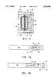
- FIG. 1is an overall schematic sectional view illustrating a potential location within a borehole of an implementation of the invention
- FIG. 2is an enlarged schematic view of a portion of the arrangement shown in FIG. 1;
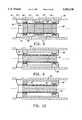
- FIG. 4is an enlarged sectional view of a portion of the construction shown in FIG. 3;
- FIG. 5is a transverse sectional view, taken on a plane indicated by the lines 5--5 in FIG. 4;
- FIG. 7Ais a schematic view corresponding to the implementation of the invention shown in FIGS. 3-6, and FIG. 7B is a variation on such implementation;
- FIGS. 8 through 11illustrate various alternate constructions
- FIG. 12illustrates in schematic form a preferred combination of such elements
- FIGS. 13A, 13B and 13Cprovide is an overall sectional view of another implementation of the instant invention.
- FIG. 14is an enlarged sectional view of a portion of the construction shown in FIG. 13;
- FIGS. 15A-15Cillustrate in schematic cross-section various constructions of a directional coupler portion of the invention.
- FIG. 16is an overall somewhat diagrammatic sectional view illustrating an implementation of the invention, a potential location within a borehole for the same;
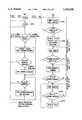
- FIG. 18is a flow chart depicting the synchronization process of the downhole acoustic transceiver portion of the preferred embodiment of FIG. 17;
- FIG. 19is a flow chart depicting the synchronization process of the surface acoustic transceiver portion of the preferred embodiment of FIG. 2;
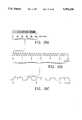
- FIG. 20A, 20B, and 20Cdepict the synchronization signal structure
- FIG. 21is a detailed block diagram of the downhole acoustic transceiver
- FIG. 23depicts the second synchronization signals and the resultant correlation signals
- FIG. 24depicts the utilization of the transducer and communication system in the present invention in a drillstring during drilling operations to transmit data between selected locations in the drillstring;
- FIGS. 25 and 26are utilized to illustrate the application of the transducer and communication system of the present invention during drilling operations for the purpose of identifying and detecting the influx of gas into a wellbore fluid column;
- FIGS. 27A, 27B and 28are block diagram representations of an alternative data communication system for the present invention.
- a boreholegenerally referred to by the reference numeral 11, is illustrated extending through the earth 12.
- Borehole 11is shown as a petroleum product completion hole for illustrative purposes. It includes a casing schematically illustrated at 13 and production tubing 14 within which the desired oil or other petroleum product flows.
- the annular space between the casing and production tubingis filled with a completion liquid represented by dots 16.
- the viscosity of this completion liquidcould be any viscosity within a wide range of possible viscosities. Its density also could be of any value within a wide range, and it may include corrosive liquid components like a high density salt such as a sodium, potassium and/or bromide compound.
- a packer represented at 17is provided to seal the borehole and the completion fluid from the desired petroleum product.
- the production tubing 14extends through the same as illustrated and may include a safety valve, data gathering instrumentation, or other tools on the petroleum side of the packer 17.
- a carrier 19 for the transducer of the inventionis provided on the lower end of the tubing 14. As illustrated, a transition section 21 and one or more reflecting sections 22 (which will be discussed in more detail below) separate the carrier from the remainder of the production tubing.
- Such carrierincludes a slot 23 within which the communication transducer of the invention is held in a conventional manner, such as by strapping or the like. A data gathering instrument, a battery pack, and other components, also could be housed within slot 23.
- the completion liquid 16which acts as the transmission medium for acoustic waves provided by the transducer, but any other fluid can be utilized for transmission, including but not limited to production fluids, drilling fluids, or fresh or salt water.
- Communication between the transducer and the annular space which confines such liquidis represented in FIGS. 1 and 2 by port 24.
- Datacan be transmitted through the port 24 to the completion liquid and, hence, by the same in accordance with the invention.
- a predetermined frequency bandmay be used for signaling by conventional coding and modulation techniques, binary data may be encoded into blocks, some error checking added, and the blocks transmitted serially by Frequency Shift Keying (FSK) or Phase Shift Keying (PSK) modulation.
- FSKFrequency Shift Keying
- PSKPhase Shift Keying
- transition section 21is to minimize the reflections caused by the mismatch between the section having the transducer and the adjacent section. It is nominally one-quarter wavelength long at the desired center frequency and the sound speed in the fluid, and it is selected to have a diameter so that the annular area between it and the casing 13 is a geometric average of the product of the adjacent annular areas, (that is, the annular areas defined by the production tubing 14 and the carrier 19). Further transition sections can be provided as necessary in the borehole to alleviate mismatches of acoustic admittances along the communication path.
- Reflections from the packerare minimized by the presence of a multiple number of reflection sections or steps below the carrier, the first of which is indicated by reference numeral 22. It provides a transition to the maximum possible annular area one-quarter wavelength below the transducer communication port. It is followed by a quarter wavelength long tubular section 25 providing an annular area for liquid with the minimum cross-sectional area it otherwise would face.
- Each of the reflection sections or stepscan be multiple number of quarter wavelengths long.
- the sections 19 and 21should be an odd number of quarter wavelengths, whereas the section 25 should be odd or even (including zero), depending on whether or not the last step before the packer 17 has a large or small cross-section. It should be an even number (or zero) if the last step before the packer is from a large cross-section to a small cross-section.
- a communication transducer for receiving the datais also provided at the location at which it is desired to have such data. In most arrangements this will be at the surface of the well, and the electronics for operation of the receiver and analysis of the communicated data also are at the surface or in some cases at another location.
- the receiving transducer 24most desirably is a duplicate in principle of the transducer being described. (It is represented in FIG. 1 by box 25 at the surface of the well).
- the communication analysis electronicsis represented by box 10.
- the acoustic transducer arrangement of the inventionis not limited necessarily to communication from downhole to the surface. Transducers can be located for communication between two different downhole locations. It is also important to note that the principle on which the transducer of the invention is based lends itself to two-way design: a single transducer can be designed to both convert an electrical communication signal to acoustic communication waves, and vice versa.
- FIGS. 3 through 6An implementation of the transducer of the invention is generally referred to by the reference numeral 26 in FIGS. 3 through 6.
- This specific designterminates at one end in a coupling or end plug 27 which is threaded into a bladder housing 28.
- a bladder 29 for pressure expansionis provided in such housing.
- the housing 28includes ports 31 for free flow into the same of the borehole completion liquid for interaction with the bladder.
- Such bladdercommunicates via a tube with a bore 32 extending through a coupler 33.
- the bore 32terminates in another tube 34 which extends into a resonator 36.
- the length of the resonatoris nominally ⁇ /4 in the liquid within resonator 36.
- the resonatoris filled with a liquid which meets the criteria of having low density, viscosity, sound speed, water content, vapor pressure and thermal expansion coefficient. Since some of these requirements are mutually contradictory, a compromise must be made, based on the condition of the application and design constraints. The best choices have thus far ben found among the 200 and 500 series Dow Corning silicone oils, refrigeration oils such as Capella B and lightweight hydrocarbons such as kerosene.
- the purpose of the bladder constructionis to enable expansion of such liquid as necessary in view of the pressure and temperature of the borehole liquid at the downhole location of the transducer.
- the transducer of the inventiongenerates (or detects) acoustic wave energy by means of the interaction of a piston in the transducer housing with the borehole liquid. In this implementation, this is done by movement of a piston 37 in a chamber 38 filled with the same liquid which fills resonator 36.
- the interaction of piston 37 with the borehole liquidis indirect: the piston is not in direct contact with such borehole liquid.
- Acoustic wavesare generated by expansion and contraction of a bellows type piston 37 in housing chamber 38.
- One end of the bellows of the piston arrangementis permanently fastened around a small opening 39 of a horn structure 41 so that reciprocation of the other end of the bellows will result in the desired expansion and contraction of the same.
- Resonator 36provides a compliant backload for this piston movement. It should be noted that the same liquid which fills the chamber of the resonator 36 and chamber 38 fills the various cavities of the piston driver to be discussed hereinafter, and the change in volumetric shape of chamber 38 caused by reciprocation of the piston takes place before pressure equalization can occur.
- piston 37made up of a steel bellows 46 (FIG. 4), is open at the surrounding horn opening 39. The other end of the bellows is closed and has a driving shaft 47 secured thereto.
- the horn structure 41communicates the resonator 36 with the piston, and such resonator aids in assuring that any acoustic energy generated by the piston that does not directly result in movement of isolating diaphragms 42 will reinforce the oscillatory motion of the piston.
- the driver for the pistonincludes the driving shaft 47 secured to the closed end of the bellows.
- Such shaftalso is connected to an end cap 48 for a tubular bobbin 49 which carries two annular coils or windings 51 and 52 in corresponding, separate radial gaps 53 and 54 (FIG. 6) of a closed loop magnetic circuit to be described, but a greater number of bobbins could be utilized.
- Such bobbinterminates at its other end in a second end cap 55 which is supported in position by a flat spring 56.
- Spring 56centers the end of the bobbin to which it is secured and constrains the same to limited movement in the direction of the longitudinal axis of the transducer, represented in FIG. 4 by line 57.
- a similar flat spring 58is provided for the end cap 48.
- a magnetic circuit having a plurality of gapsis defined within the housing.
- a cylindrical permanent magnet 60is provided as part of the driver coaxial with the axis 57.
- Such permanent magnetgenerates the magnetic flux needed for the magnetic circuit and terminates at each of its ends in a pole piece 61 and 62, respectively, to concentrate the magnetic flux for flow through the pair of longitudinally spaced apart gaps 53 and 54 in the magnetic circuit.
- the magnetic circuitis completed by an annular magnetically passive member of magnetically permeable material 64. As illustrated, such member includes a pair of inwardly directed annular flanges 66 and 67 which terminate adjacent the windings 51 and 52 and define one side of the gaps 53 and 54.
- the magnetic circuit formed by this implementationis represented in FIG. 6 by closed loop magnetic flux lines 68. As illustrated, such lines extend from the magnet 60, through pole piece 61, across gap 53 and coil 51, through the return path provided by member 64, through gap 54 and coil 52, and through pole piece 62 to magnet 60. With this arrangement, it will be seen that magnetic flux passes radially outward through gap 53 and radially inward through gap 54. Coils 51 and 52 are connected in series opposition, so that current in the same provides additive force on the common bobbin. Thus, if the transducer is being used to transmit a communication, an electrical signal defining the same is passed through the coils 51 and 52 will cause corresponding movement of the bobbin 49 and, hence, the piston 37. Such piston will interact through the windows 43 with the borehole liquid and impart the communicating acoustic energy thereto. Thus, the electrical power represented by the electrical signal is converted by the transducer to mechanical power, in the form of, acoustic waves.
- the acoustic energy defining the samewill flex the diaphragms 42 and correspondingly move the piston 37. Movement of the bobbin and windings within the gaps 51 and 52 will generate a corresponding electrical signal in the coils 51 and 52 in view of the lines of magnetic flux which are cut by the same. In other words, the acoustic power is converted to electrical power.
- the permanent magnet 60 and its associated pole pieces 61 and 62are generally cylindrical in shape with the axis 57 acting as an axis of a figure of revolution.
- the bobbinis a cylinder with the same axis, with the coils 51 and 52 being annular in shape.
- Return path member 64also is annular and surrounds the magnet, etc.
- the magnetis held centrally by support rods 71 projecting inwardly from the return path member, through slots in bobbin 49.
- the flat springs 56 and 58correspondingly centralize the bobbin while allowing limited longitudinal motion of the same as aforesaid.
- Suitable electrical leads 72 for the windings and other electrical partspass into the housing through potted feedthroughs 73.
- FIG. 7Aillustrates the implementation described above in schematic form.
- the resonatoris represented at 36, the horn structure at 41, and the piston at 37.
- the driver shaft of the pistonis represented at 47, whereas the driver mechanism itself is represented by box 74.
- FIG. 7Bshows an alternate arrangement in which the driver is located within the resonator 76 and the piston 37 communicates directly with the borehole liquid which is allowed to flow in through windows 43.
- the windowsare open; they do not include a diaphragm or other structure which prevents the borehole liquid from entering the chamber 38. It will be seen that in this arrangement the piston 37 and the horn structure 41 provide fluid-tight isolation between such chamber and the resonator 36.
- the resonator 36could be designed for the resonator 36 to be flooded by the borehole liquid. It is desirable, if it is designed to be so flooded, that such resonator include a small bore filter or the like to exclude suspended particles. In any event, the driver itself should have its own inert fluid system because of close tolerances, and strong magnetic fields. The necessary use of certain materials in the same makes it prone to impairment by corrosion and contamination by particles, particularly magnetic ones.
- FIGS. 8 through 12are schematic illustrations representing various conceptual approaches and modifications for the invention, considered by applicant.
- FIG. 8illustrates the modular design of the invention.
- the inventionis to be housed in a pipe of restricted diameter, but length is not critical.
- the inventionenables one to make the best possible use of cross-sectional area while multiple modules can be stacked to improve efficiency and power capability.
- the bobbinrepresented at 81 in FIG. 8, carries three separate annular windings represented at 82-84.
- a pair of magnetic circuitsare provided, with permanent magnets represented at 86 and 87 with facing magnetic polarities and poles 88-90.
- Return paths for both circuitsare provided by an annular passive member 91.
- the two magnetic circuits of the FIG. 8 configurationhave the central pole 89 and its associated gap in common.
- the resultis a three-coil driver with a transmitting efficiency (available acoustic power output/electric power input) greater than twice that of a single driver, because of the absence of fringing flux at the joint ends.
- the process of "stacking" two coil drivers as indicated by this arrangement with alternating magnet polaritiescan be continued as long as desired with the common bobbin being appropriately supported.
- the bobbinis connected to a piston 85 which includes a central domed part and bellows of the like sealing the same to an outer casing represented at 92.
- This flexure seal supportis preferred to sliding seals and bearings because the latter exhibit restriction that introduced distortion, particularly at the small displacements encountered when the transducer is used for receiving.
- a rigid pistoncan be sealed to the case with a bellows and a separate spring or spider used for centering.
- a spider represented at 94can be used at the opposite end of the bobbin for centering the same. If such spider is metal, it can be insulated from the case and can be used for electrical connections to the moving windings, eliminating the flexible leads otherwise required.
- the magnet 86is made annular and it surrounds a passive flux return path member 91 in its center. Since passive materials are available with saturation flux densities about twice the remanence of magnets, the design illustrated has the advantage of allowing a small diameter of the poles represented at 88 and 90 to reduce coil resistance and increase efficiency.
- the passive flux return path member 91could be replaced by another permanent magnet.
- a two- magnet designcould permit a reduction in length of the driver.
- FIG. 10schematically illustrates another magnetic structure for the driver. It includes a pair of oppositely radially polarized annular magnets 95 and 96. As illustrated, such magnets define the outer edges of the gaps. In this arrangement, an annular passive magnetic member 97 is provided, as well as a central return path member 91. While this arrangement has the advantage of reduced length due to a reduction of flux leakage at the gaps and low external flux leakage, it has the disadvantage of more difficult magnet fabrication and lower flux density in such gaps.
- FIGS. 13A, 13B, and 13C and 14An implementation of the invention incorporating some of the features mentioned above is illustrated in FIGS. 13A, 13B, and 13C and 14.
- Such implementationincludes two magnetic circuits, annular magnets defining the exterior of the magnetic circuit and a central pole piece.
- the pistonis in direct contact with the borehole liquid and the resonant chamber is filled with such liquid.
- FIGS. 13A, 13B and 13C, and 14is similar in many aspects to the implementation illustrated and described with respect to FIGS. 3 and 6. Common parts will be referred to by the same reference numerals used earlier but with the addition of prime component. This implementation includes many of the features of he earlier one, which features should be considered as being incorporated within the same, unless indicated otherwise.
- FIGS. 13A, 13B and 13C, and 14The implementation of FIGS. 13A, 13B and 13C, and 14 is generally referred to by the reference numeral 120.
- the resonator chamber 36'is downhole of this piston 37' and its driver, in this arrangement, and is allowed to be filled with borehole liquid rather than being filled with a special liquid as described in connection with the earlier implementation.
- the bladder and its associated housingis eliminated and the end plug 27' is threaded directly into the resonator chamber 36.
- Such end plugincludes a plurality of elongated bores 122 which communicate the borehole with tube 34' extending in to the resonator 36.
- the tube 34'is nominally a quarter of the communication frequency in the resonator fluid (the borehole liquid in this implementation).
- the diameter of the bores 122is selected relative to the interior diameter of tube 34' to assure that no particulate matter of sufficient size from the borehole liquid can enter and block the tube enter the same.
- Piston 37'is a bellows as described in the earlier implementation and acts to isolate the driver for the same to be described from a chamber 38' which is allowed to be filled with the borehole liquid.
- chamber 38'is illustrated as having two parts, parts 123 and 124, that communicate directly with one another.
- windows 43'extend to the annulus surrounding the transducer construction without the intermediary of isolating diaphragms as in the previous implementation.
- the piston 37'is in direct contact with borehole liquid which fills the chamber 38'.
- the piston 37'is connected via a nut 127 and driving shaft 128 to the driver mechanism.
- the driving shaft 128is connected to an end cap 48' of a tubular bobbin 49'.
- the bobbin 49'carries three annular coils or windings in a corresponding number of radial gaps of two closed loop magnetic circuits to be described. Two of these windings are represented at 128 and 129. The third winding is on the axial side of winding 129 opposite that of winding 128 in accordance with the arrangement shown in FIG. 8. Moreover, winding 129 is twice the axial length of winding 128.
- the bobbin 49'is constrained in position similarly to bobbin 49' by springs 56' and 58'.
- the driver in this implementationconceptually is a hybrid of the approaches illustrated in FIGS. 8 and 9. That is, it includes two adjacent magnetic circuits sharing a common pathway. Moreover, the permanent magnets are annular surrounding a solid core providing a passive member. In more detail, three magnets illustrated in FIG. 14 at 131, 132 and 133, develop flux which flows across the gaps within which the windings previously described ride to a solid, cylindrical core passive member 132.
- the magnetic circuitsare completed by an annular casing 134 which surrounds the magnets. Such casing 134 is fluid tight and acts to isolate the driver as described from the borehole liquid.
- an isolation bellows 136which transmits pressure changes caused in the driver casing 132 to the resonator 36'.
- the bellows 136is free floating in the sense that it is not physically connected to the tubular bobbin 49' and simply flexes to accommodate the pressure changes of the special fluid in the driver casing. It sits within a central cavity or borehole 37 within a plug 38 that extends between the driver casing and the wall of the resonant chamber 36'.
- An elongated hole or aperture 139connects the interior of bellows 136 with the resonator chamber.
- FIGS. 15A-15CA passive directional coupling arrangement is conceptually illustrated by FIGS. 15A-15C.
- the piston of the transduceris represented at 220. Its design is based on the fact that the acoustic characteristic admittance in a cylindrical waveguide is proportional to its cross-sectional area.
- the windows for transmission of the communicating acoustic energy to the borehole fluidare represented at 221.
- a second port or annular series of ports 222are located either three one-quarter wavelength section (FIG. 15A) or one-quarter wavelength sections (FIGS. 15B and C) from the windows 221.
- the coupleris divided into three quarter wavelength sections 223-226. The cross-sectional area of these sections are selected to minimize any mismatch which might defeat directional coupling.
- Center section 224has a cross-sectional area A 3 which is nominally equal to the square of the cross-sectional area of sections 223 and 226 (A 2 ) divided by the annular cross-section of the borehole at the location of the ports 221 and 222.
- the reduced cross-sectional area of section 224is obtained by including an annular restriction 227 in the same.
- the version of the directional coupler represented in FIG. 15Ais full length, requiring a three-quarter wavelength long tubing, i.e., the chamber is divided into three, quarter-wavelength-long sections.
- the versions represented in FIGS. 15B and 15Care folded versions, thereby reducing the length required. That is, the version in FIG. 15B is folded once with the sectional areas of the sections meeting the criteria discussed previously. Two of the chamber sections are coaxial with one another.
- the version represented in FIG. 15Cis folded twice. That is, all three sections are coaxial.
- the two versions in FIGS. 15B and 15Care one-fourth wavelength from the port 222 and thus are on the "uphole" side of port 221 as illustrated. It will be recognized, though, that the bandwidth of effective directional coupling is reduced with folding.
- the port 222could contain a diaphragm or bellows, an expansion chamber could be added, and a filling fluid other than well fluid could be used. Additional contouring of area could also be done to modify coupling bandwidth and efficiency. Shaping of ports and arraying of multiple ports could also be done for the same purpose.
- Directional couplingalso could be obtained by using two or more transducers of the invention as described with ports axially separated to synthesize a phased array.
- the directional couplingwould be achieved by driving each transducer with a signal appropriately predistorted in phase and amplitude.
- Such active directional couplingcan be achieved over a wider bandwidth than that achieved with a passive system.
- the predistortion functionswould have to account for all coupled resonances in each particular situation.
- a boreholegenerally referred to by the reference numeral 1100, is illustrated extending through the earth 1102.
- Borehole 1100is shown as a petroleum product completion hole for illustrative purposes. It includes a casing schematically illustrated at 1104 and production tubing 1106 within which the desired oil or other petroleum product flows.
- the annular space between the casing and production tubingis filled with borehole completion liquid represented by dots 1108.
- the properties of a completion fluidvary significantly from well to well and over time in any specific well. It typically will include suspended particles or partially be a gel. It is non-Newtonian and may include non-linear elastic properties. Its viscosity could be any viscosity within a wide range of possible viscosities. Its density also could be of any value within a wide range, and it may include corrosive solid or liquid components like a high density salt such as a sodium, calcium, potassium and/or a bromide compound.
- a carrier 1112 for a downhole acoustic transceiver (DAT) and its associated transduceris provided on the lower end of the tubing 1106. As illustrated, a transition section 1114 and one or more reflecting sections 1116, most desirably are included and separate carrier 1112 from the remainder of production tubing 1106.
- Carrier 1112includes numerous slots in accordance with conventional practice, within one of which, slot 1118, the communication transducer (DAT) of the invention is held by strapping or the like.
- One or more data gathering instruments or a battery packalso could be housed within slots like slot 1118. In the preferred embodiment, one slot is utilized to house a battery pack, and another slot (slot 1118) is utilized to house the transducer and associated electronics.
- completion liquid 1108which acts as the transmission medium for acoustic waves provided by the transducer. Communication between the transducer and the annular space which confines such liquid is represented in FIG. 16 by port 1120. Data can be transmitted through the port 1120 to the completion liquid via acoustic signals. Such communication does not rely on flow of the completion liquid.
- a surface acoustic transceiver (SAT) 1126is provided at the surface, communicating with the completion liquid in any convenient fashion, but preferably utilizing a transducer in accordance with the present invention.
- the surface configuration of the production wellis diagrammatically represented and includes an end cap on casing 1104.
- the production tubing 1106extends through a seal represented at 1122 to a production flow line 1123.
- a flow line for the completion fluid 1124is also illustrated, which extends to a conventional circulation system.
- the arrangementconverts information laden data into an acoustic signal which is coupled to the borehole liquid at one location in the borehole.
- the acoustic signalis received at a second location in the borehole where the data is recovered.
- communicationoccurs between both locations in a bidirectional fashion.
- communicationcan occur between multiple locations within the borehole such that a network of communication transceivers are arrayed along the borehole.
- communicationcould be through the fluid in the production tubing through the product which is being produced.
- Many of the aspects of the specific communication method describedare applicable as mentioned previously to communication through other transmission medium provided in a borehole, such as in the walls of the tubing 1106.
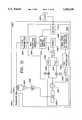
- the downhole acoustic transducer (DAT) 1200 at the downhole locationis coupled to a downhole acoustic transceiver (DAT) data acquisition system 1202 for acoustically transmitting data collected from the DAT's associated sensors 1201.
- the downhole acoustic transceiver (DAT) data acquisition system 1202includes signal processing circuitry, such as impedance matching circuits, amplifier circuits, filter circuits, analog-to-digital conversion circuits, power supply circuits, and a microprocessor and associated circuitry.
- the DAT 1202is capable of both modulating an electrical signal used to stimulate the transducer 1200 for transmission, and of demodulating signals received by the transducer 1200 from the surface acoustic transceiver (SAT) 1204 data acquisition system.
- the surface acoustic transceiver (SAT) data acquisition system 1204includes signal processing circuitry, such as impedance matching circuits, amplifier circuits, filter circuits, analog-to-digital conversion circuits, power supply circuits, and a microprocessor and associated circuitry.
- the DAT 1202both receives and transmits information.
- the SAT 1204both receives and transmits information.
- the communicationis directly between the DAT 1202 and the SAT 1204 through transducers 1200, 1205.
- intermediary transceiverscould be positioned within the borehole to accomplish data relay. Additional DATs could also be provided to transmit independently gathered data from their own sensors to the SAT or to another DAT.
- the bi-directional communication system of the inventionestablishes accurate data transfer by conducting a series of steps designed to characterize the borehole communication channel 1206, choose the best center frequency based upon the channel characterization, synchronize the SAT 1204 with the DAT 1202, and, finally, bi-directionally transfer data.
- This complex processis undertaken because the channel 1206 through which the acoustic signal must propagate is dynamic, and this time variant.
- the channelis forced to be reciprocal: the transducers are electrically loaded as necessary to provide for reciprocity.
- the inventive communication systemcharacterizes the channel in the uphole direction 1210. To do so, the DAT 1202 sends a repetitive chirp signal which the SAT 1204, in conjunction with its computer 1128, analyzes to determine the best center frequency for the system to use for effective communication in the uphole direction.
- the channel 1210is characterized only in the uphole direction; thus, an implicit assumption of reciprocity is incorporated into the design. It will be recognized that the downhole direction 1208 could be characterized rather than, or in addition to, characterization for uphole communication.
- the bit rate of the data transmitted by the DAT 1202may be higher than the commands sent by the SAT 1204 to the DAT 1202. Thus, it is advantageous to achieve the best signal to noise ratio for the uphole signals.
- each transceivercould be designed to characterize the channel in the incoming communication direction: the SAT 1204 could analyze the channel for uphole communication 1210 and the DAT 1202 could analyze for downhole communication 1208, and then command the corresponding transmitting system to use the best center frequency for the direction characterized by it.
- this alternativewould require extra processing capability in the DAT 1202. Extra processing capability means greater power and size requirements which are, in most instances, undesirable.
- system timing synchronizationis important to any coherent communication system.
- the DATbegins transmitting repetitive chirp sequences after a programmed time delay selected to be longer than the expected lowering time.
- FIGS. 20A-Cdepict the signalling structure for the chirp sequences.
- a single chirp blockis one hundred milliseconds in duration and contains three cycles of one hundred fifty (150) Hertz signal, four cycles of two hundred (200) Hertz signal, five cycles of two hundred and fifty (250) Hertz signal, six cycles of three hundred (300) Hertz signal, and seven cycles of three hundred and fifty (350) Hertz cycles.
- the chirp signal structureis depicted in FIG. 20A.
- the entire bandwidth of the desired acoustic channel, one hundred and fifty to three hundred and fifty (150-350) Hertzis chirped by each block.
- the chirp blockis repeated with a time delay between each block.
- this sequenceis repeated three times at two minute intervals. The first two sequences are transmitted sequentially without any delay between them, then a delay is created before a third sequence is transmitted. During most of the remainder of the interval, the DAT 1202 waits for a command (or default tone) from the SAT 1204.
- the specific sequence of chirp signalsshould not be construed as limiting the invention: variations on the basic scheme, including but not limited to different chirp frequencies, chirp durations, chirp pulse separations, etc., are foreseeable. It is also contemplated that PN sequences, an impulse, or any variable signal which occupies the desired spectrum could be used.
- the SAT 1204 of the preferred embodiment of the inventionuses two microprocessors 1616, 1626 to effectively control the SAT functions, as is illustrated in FIG. 22.
- the host computer 1128controls all of the activities of the SAT 1204 and is connected thereto via one of two serial channels of a Model 68000 microprocessor 1626 in the SAT 1204.
- the SAT 1204may be mounted on an input/output card which is adapted in size to be inserted within an expansion slot of a host computer.
- the 68000 microprocessoraccomplishes the bulk of the signal processing functions that are discussed below.
- the second serial channel of the 68000 microprocessoris connected to a 68HC11 processor 1616 that controls the signal digitization, the retrieval of received data, and the sending of tones and commands to the DAT.
- the chirp sequenceis received from the DAT by the transducer 1205 and converted into an electrical signal from an acoustic signal.
- the electrical signalis coupled to the receiver through transformer 1600 which provides impedance matching.
- Amplifier 1602increases the signal level, and the bandpass filter 1604 limits the noise bandwidth to three hundred and fifty (350) Hertz centered at two hundred and fifty (250) Hertz and also functions as an anti-alias filter.
- the DAT 1202has a single 68HC11 microprocessor 1512 that controls all transceiver functions, the data logging activities, logged data retrieval and transmission, and power control. For simplicity, all communications are interrupt-driven. In addition, data from the sensors are buffered, as represented by block 1510, as it arrives. Moreover, the commands are processed in the background by algorithms 1700 which are specifically designed for that purpose.
- the DAT 1202 and SAT 1204include, though not explicitly shown in the block diagrams of FIGS. 21 and 22, all of the requisite microprocessor support circuitry. These circuits, including RAM, ROM, clocks, and buffers, are well known in the art of microprocessor circuit design.
- the chirp generation circuitryis depicted as block 1500 in FIG. 21, a block diagram of the DAT 1202. Note that the digital output is used to generate a three level signal at 1502 for driving the transducer 1200. It is chosen for this application to maintain most of the signal energy in the acoustic spectrum of interest: one hundred and fifty Hertz to three hundred and fifty Hertz.
- the primary purpose of the third stateis to terminate operation of the transmitting portion of a transceiver during its receiving mode: it is, in essence, a short circuit.
- FIG. 18 and FIG. 19are flow charts of the DAT and SAT operations, respectively.
- the chirp sequencesare generated during step 1300.
- the surface transceiverPrior to the first chirp pulse being transmitted after the selected time delay, the surface transceiver awaits the arrival of the chirp sequences in accordance with step 1400 in FIG. 19.
- the DATis programmed to transmit a burst of chirps every two minutes until it receives two tones: fc and fc+1.
- Initial synchronizationstarts after a "characterize channel” command is issued at the host computer.
- the SATstarts digitizing transducer data.
- the raw transducer datais conditioned through a chain of amplifiers, anti-aliasing filters, and level translators, before being digitized.
- One second data block (1024 samples)is stored in a buffer and pipelined for subsequent processing.
- the functions of the chirp correlatorare threefold. First, it synchronizes the SAT TX/RX clock to that of the DAT. Second, it calculates a clock error between the SAT and DAT timebases, and corrects the SAT clock to match that of the DAT. Third, it calculates a one Hertz resolution channel spectrum.
- the correlatorperforms a FFT ("Fast Fourier Transform") on a 0.25 second data block, and retains FFT signal bins between one hundred and forty Hertz to three hundred and sixty Hertz.
- the complex valued signalis added coherently to a running sum buffer containing the FFT sum over the last six seconds (24 FFTs).
- the FFT binsare incoherently added as follows: magnitude squared, to a running sum over the last 6 seconds.
- An estimate of the signal to noise ratio (SNR) in each frequency binis made by a ratio of the coherent bin power to an estimated noise bin power.
- the noise power in each frequency binis computed as the difference of the incoherent bin power minus the coherent bin power.
- an "SNR sum"is computed by summing the individual bin SNRs.
- the SNR sumis added to the past twelve and eighteen second SNR sums to form a correlator output every 0.25 seconds and is stored in an eighteen second circular buffer.
- a phase angle in each frequency binis calculated from the six second buffer sum and placed into an eighteen second circular phase angle buffer for later use in clock error calculations.
- the correlator peakis found by comparing each correlator point to a noise floor plus a preset threshold. After detecting a chirp, all subsequent SAT activities are synchronized to the time at which the peak was found.
- an estimate of sampling clock difference between the SAT and DATis computed using the eighteen second circular phase angle buffer.
- Phase angle difference ( ⁇ ) over a six second time intervalis computed for each frequency bin.
- a first clock error estimationis computed by averaging the weighted phase angle difference over all the frequency bins.
- Second and third clock error estimationsare similarly calculated respectively over twelve and one hundred and eighty-five second time intervals.
- a weighted average of three clock error estimatesgives the final clock error value.
- the SAT clockis adjusted and further clock refinement is made at the next two minute chirp interval in similar fashion.
- the SATwaits for the next set of chirps at the two minute interval and averages twenty-four 0.25 second chirps over the next six seconds.
- the averaged datais zero padded and then FFT is computed to provide one Hertz resolution channel spectrum.
- the surface systemlooks for a suitable transmission frequency in the one hundred and fifty Hertz to three hundred and fifty Hertz. Generally, a frequency band having a good signal to noise ratio and bandwidths of approximately two Hertz to forty Hertz is acceptable. A width of the available channel defines the acceptable baud rate.
- the second phase of the initial communication processinvolves establishing an operational communication link between the SAT 1204 and the DAT 1202. Toward this end, two tones, each having a duration of two seconds, are sequentially sent to the DAT 1202. One tone is at the chosen center frequency and the other is offset from the center frequency by exactly one hertz. This step in the operation of the SAT 1204 is represented by block 1406 in FIG. 19.
- the DATis always looking for these two tones: fc and fc+1, after it has stopped chirping. Before looking for these tones, it acquires a one second block of data at a time when it is known that there is no signal.
- the noise collectiongenerally starts six seconds after the chirp ends to provide time for echoes to die down, and continues for the next thirty seconds. During the thirty second noise collection interval, a power spectrum of one second data block is added to a three second long running average power spectrum as often as the processor can compute the 1024 point (one second) power spectrum.
- the DATstarts looking for the two tones approximately thirty-six seconds after the end of the chirp and continues looking for them for a period of four seconds (tone duration) plus twice the maximum propagation time.
- the DATagain calculates the power spectrum of one second blocks as fast as it can, and computes signal to noise ratios for each one Hertz wide frequency bins. All the frequency components which are a preset threshold above a noise floor are possible candidates. If a frequency is a candidate in two successive blocks, then the tone is detected at its frequency. If the tones are not recognized, the DAT continues to chirp at the next two minute interval.
- the DATWhen the tones are received and properly recognized by the DAT, the DAT transmits the same two tones back to the SAT at the selected carrier frequency fc, which is recognized as an acknowledgement signal. Then, the SAT transmits characters to the DAT, which causes the DAT to look for a coded "recognition sequence signal". Control data follows the recognition signal.
- the recognition sequence signalincludes a baud rate signal which identifies to the DAT the expected baud rate, as determined by the SAT. The DAT will then respond to any command provided to it after the recognition sequence signal.
- the SATwill command the DAT to begin the transmission of data from the downhole location for receipt by the SAT at the uphole location.
- a by-product of the process of recognizing the tonesis that it enables the DAT to synchronize its internal clock to the surface transceiver's clock.
- the clock in the surface transceiverproduces a tick every second as depicted in FIG. 23. This alignment is desirable to enable each clock to tick off seconds synchronously and maintain coherency for accurately demodulating the data.
- the DATis not sure when it will receive the pair, so it conducts an FFT every second relative to its own internal clock which can be assumed not to be aligned with the surface clock.
- FIG. 23is helpful in visualizing this arrangement. Note that the FFT periods having a full one second of tone signal located within it will produce a maximum FFT peak.
- an FFT of each two second toneproduces both amplitude and phase components of the signal.
- phase of the second tonewill be two hundred and seventy degrees from that of the first tone. Consequently, the difference between the phases of each tone is two hundred and seventy degrees which corresponds to an offset of 0.75 seconds between the clocks. If the DAT adjusts its clock by 0.75 seconds, the one second ticks will be aligned. In general, the phase difference defines the time offset. This offset is corrected in this implementation.
- the timing correction processis represented by step 1308 in FIG. 18 and is accomplished by the software in the DAT, as represented by blocks 1504, 1506, 1508 in the DAT block diagram of FIG. 21.
- the tonesare generated in both the DAT and SAT in the same manner as the chirp signals were generated in the DAT.
- a microprocessor controlled digital signal generator 1500, 1628creates a pulse stream of any frequency in the band of interest. Subsequent to generation, the tones are converted into a three level signal at 1502, 1630 for transmission by the transducer 1200, 1205 through the acoustic channel.
- the DATAfter tone recognition and retransmission, the DAT adjusts its clock, then switches to the Minimum Shift Keying (MSK) modulation receiving mode. (Any modulation technique can be used, although it is preferred that MSK be used for the invention for the reasons discussed below.) Additionally, if the tones are properly recognized by the SAT as being identical to the tones which were sent (step 1408), it transmits a MSK modulated command instructing the DAT as to what baud rate the downhole unit should use to send its data to achieve the best bit energy to noise ratio at the SAT (step 1410).
- the DATis capable of selecting 2 to 40 baud in 2 baud increments for its transmissions.
- the communication link in the downhole directionis maintained at a two baud rate, which rate could be increased if desired. Additionally, the initial message instructs the downhole transceiver of the proper transmission center frequency to use for its transmissions.
- the tonesare not received by the downhole transceiver, it will revert to chirping again.
- SATdid not receive the two tone acknowledgement signal since DAT did not transmit them. In this case the operator can either try sending tones however many times he wants to or try recharacterizing channel which will essentially resynchronize the system. In the case of sending two tones again, SAT will wait until the next tone transmit time during which the DAT would be listening for the tones.
- the DATwill have switched to this MSK mode to await the MSK commands, and it will not be possible for it to detect the tones which are transmitted a second time, if the operator decides to retransmit rather than to recharacterize. Therefore, the DAT will wait a set duration. If the MSK command is not received during that period, it will switch back to the synchronization mode and begin sending chirp sequences every two minutes. This same recovery procedure will be implemented if the established communication link should subsequently deteriorate.
- MSKis a form of modulation which, in effect, is binary frequency shift keying (FSK) having continuous phase during the frequency shift occurrences.
- FSKbinary frequency shift keying
- BPSKbinary phase shift keying
- QPSKquadrature phase shift keying
- any one of the many forms of modulationcould be used in this acoustic communication system.
- the commandsare generated by the host computer 1128 as digital words.
- Each commandis encoded by a cyclical redundancy code (CRC) to provide error detection and correction capability.
- CRCcyclical redundancy code
- the encoded commandis sent to the MSK modulator portion of the 68HC11 microprocessor's software.
- the encoded command bitscontrol the same digital frequency generator 1628 used for tone generation to generate the MSK modulated signals.
- each encoded command bitis mapped, in this implementation, onto a first frequency and the next bit is mapped to a second frequency.
- the datamay be mapped onto frequencies two hundred and eighteen Hertz, representing a "1", and two hundred and eight Hertz, representing a "0".
- the transitions between the two frequenciesare phase continuous.
- the DATUpon receiving the baud rate command, the DAT will send an acknowledgement to the SAT. If an acknowledgement is not received by the SAT, it will resend the baud rate command if the operator decides to retry. If an operator wishes, the SAT can be commanded to resynchronize and recharacterize with the next set of chirps.
- a commandis sent by the SAT to instruct the DAT to begin sending data. If an acknowledgement is not received, the operator can resend the command if desired.
- the SATresets and awaits the chirp signals if the operator decides to resynchronize. However, if an acknowledgement is sent from the DAT, data are automatically transmitted by the DAT directly following the acknowledgement. Data are received by the SAT at the step represented at 1434.
- the downhole transceiverwill transmit for four minutes and then stop and listen for the next command from the SAT. Once the command is received, the DAT will transmit another 4 minute block of data. Alternatively, the transmission period can be programmed via the commands from the surface unit.
- the DATmay include buffer memory 1510 to store the incoming data from the sensors 1201 for a short duration prior to transmitting it to the surface.
- the datais encoded and MSK modulated in the DAT in the same manner that the commands were encoded and modulated in the SAT, except the DAT may use a higher data rate: two to forty baud, for transmission.
- the CRC encodingis accomplished by the microprocessor 1512 prior to modulating the signals using the same circuitry 1500 used to generate the chirp and tone bursts.
- the MSK modulated signalsare converted to tri-state signals 1502 and transmitted via the transducer 1200.
- the digitized dataare processed by a quadrature demodulator.
- the sine and cosine waveforms generated by oscillators 1635, 1636are centered at the center frequency originally chosen during the synchronization mode.
- the phase of each oscillatoris synchronized to the phase of the incoming signal via carrier transmission.
- the phase of the incoming signalis tracked to maintain synchrony via a phase tracking system such as a Costas loop or a squaring loop.
- a decoder 1642which matches the encoder used in the transmitter process: a CRC decoder, decodes and detects errors in the received data.
- the decoded information carrying datais used to instruct the DAT to accomplish a new task, to instruct the SAT to receive a different baud rate, or is stored as received sensor data by the SAT's host computer.
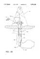
- FIG. 24shows one such utilization of the transducer and communication system during drilling operations.
- wellbore 601extends from surface 603 to bottom hole 605.
- Drillstring 607is disposed therein, and is composed of a section of drill pipe 609 and a section of drill collar 611.
- the drill collar 611is located at the lowermost portion of drillstring 607, and terminates at its lowermost end at rockbit 613.
- fluidis circulated downward through drillstring 607 to cool and lubricate drillbit 613, and to wash formation cuttings upward through annulus 615 of wellbore 601.
- a fluid columnexists within drillstring 607, and a fluid column exists within annulus 615 which is between drillstring 607 and wellbore 601.
- a measurement-while-drilling data transmission systemwhich impresses a series of either positive or negative pressure pulses upon the fluid within annulus 615 to communicate data from drill collar section 611 to surface 603.
- a measurement-while-drilling data transmission systemincludes a plurality of instruments for measuring drilling conditions, such as temperature and pressure, and formation conditions such as formation resistivity, formation gamma ray discharge, and formation dielectric properties. It is conventional to utilize measurement-while-drilling systems to provide to the operator at the surface information pertaining to the progress of the drilling operations as well as information pertaining to characteristics or qualities of the formations which have been traversed by rockbit 613.
- measurement-while-drilling subassembly 617includes sensors which detect information pertaining to drilling operations and surrounding formations, as well as the data processing and data transmission equipment necessary to coherently transmit data from drill collar 611 to surface 603.
- the utilization of steering equipmentensures that the measurement-while-drilling data gathering and transmission equipment is located thirty to sixty (30-60) feet from drill bit 613.
- Directional turns of drillbit 613cannot be accurately monitored and controlled utilizing the sensing and data transmission equipment of measurement-while-drilling system 617; near drillbit information would be required in order to have a higher degree of control.
- Some examples of desirable near drillbit datainclude: inclination of the lowermost portion of the drilling subassembly, the azimuth of the lowermost portion of the drilling subassembly, drillbit temperature, mud motor or turbine rpm, natural gamma ray readings for freshly drilled formations near the bit, resistivity readings for freshly drilled formations near the bit, the weight on the bit, and the torque on the bit.
- measurement subassembly 619is located adjacent rockbit 613, and includes a plurality of conventional instruments for measuring near drillbit data such as inclination, azimuth, bit temperature, turbine rpm, gamma ray activity, formation resistivity, weight on bit, and torque on bit, etc.
- This informationmay be digitized and multiplexed in a conventional fashion, and directed to acoustic transducer 623 which is located in an adjacent subassembly for transmission to receiver 625, which is located upward within the string, and which is adjacent measurement-while-drilling subassembly 617.
- near-drillbit datamay be transmitted a short distance (typically thirty to ninety feet) between transmitter 623 and receiver 625 which utilize the transducer of the present invention as well as the communication system of the present invention.
- the communication system of the present inventioncontinually monitors the fluid within annulus 615 with a characterization signal to identify the optimum frequencies for communication, as was discussed above.
- the datamay be routed from receiver 625 to measurement-while-drilling system 617 for storage, processing, and retransmission to surface 603 utilizing conventional measurement-while-drilling data transmission technologies.
- Thisprovides an economical and robust data communication system for the dynamic and noisy environment adjacent drill collar section 611, which allows communication of near-drillbit data for integration into a conventional data stream from a measurement-while-drilling data communication system.
- transducer 627may be provided at surface 603 for receipt of acoustic data signals from either one or both of transducer 623 or transducer 625.
- transducer 625may be utilized to transmit to an intermediate transducer located in the drillpipe section 609 of the drillstring 611 which will be able to transmit a greater distance than transducers located in the drill collar section 611.
- the transducers and communication system of the present inventionmay be utilized as a data transmission system which is parallel with a conventional measurement-while-drilling data transmission system. This is particularly useful, since conventional measurement-while-drilling systems require the continuous flow of fluid downward through drillstring 607.
- the transducer and communication system of the present inventionprovide a redundant system which can be utilized to transmit data to surface 603 during quiescent periods when no fluid is being circulated within the wellbore. This provides considerable advantages since there are significant periods of time during which data communication is not possible during drilling operations utilizing conventional measurement-while-drilling technologies.
- the transducer and communication system of the present inventioncan be utilized to completely replace a conventional measurement-while drilling data transmission system, and provide a sole mechanism for the communication of data and control systems within the wellbore during drilling operations.
- the transducer and communication system of the present inventioncan also be utilized during drilling operations for the detection of the undesirable influx of high pressure gas into the annulus of a wellbore.
- the introduction of high pressure gas into the fluid column of a wellbore during drilling operationscan result in loss of control of the well, or even a "blowout" in the most extreme situations.
- Considerable efforthas been expended to provide safety equipment at the wellhead which can be utilized to prevent the total loss of control of a well.
- remedial actionscan be taken to lessen the impact of the gas influx.
- remedial actionsinclude increasing or decreasing circulation within the well, or increasing the viscosity and density of the drilling fluid within the well.
- the transducer and communication system of the present inventioncan be utilized in drilling operations to provide the operator with significant data pertaining to (1) whether an undesirable influx of gas has occurred, and (2) the location of the gas "bubble" once it has entered the drilling fluid column. It is important to note that an influx usually occurs as an introduction of a fluid slug, which is the gas in liquified form due to the high pressure exerted by the fluid column. Since the gas generally has a lower density, it will rise within the fluid column; as it rises, it will come out of solution, and take the form of a gas "bubble".
- an influx of gascan be detected in a fluid column within a wellbore which defines a communication channel by performing the following steps:
- At least one actuatoris provided in communication with the wellbore for conversion of at least one of (a) a provided coded electrical signal to a corresponding generated coded acoustic signal during a message transmission mode of operation, and (b) a provided coded acoustic signal to a corresponding generated coded electrical signal during a message reception mode of operation; preferably, only one actuator/transducer is provided, and this is located at the surface of the wellbore at the wellhead, and is in fluid communication with the fluid column within the annulus of the wellbore, although in alternative embodiments one or more transducers may be provided downhole within the drillstring;
- the transduceris utilized to generate an interrogating signal at a selected location within the wellbore;
- the characterizing signalmay be a "chirp" which includes a plurality of signal components, each having a different frequency, and spanning over a preselected range of frequencies, or it may be an acoustic signal which includes only a single frequency component;
- the transduceris utilized to apply the interrogating signal to the communication channel which is defined, preferably, in the fluid column within the wellbore annulus;
- the interrogating signalis transmitted through the communication channel and is received by either a different transducer, or is echoed back upward through the communication channel and received by the transmitting transducer;
- the interrogating signalis analyzed to identify at least one of the following: (a) portions of a preselected range of frequencies which are suitable for communicating data in the wellbore; these portions may be identified by either frequency or bandwidth or both, or by signal-to-noise characteristics such as a signal-to-noise ratio, or signal amplitude; (b) communication channel attributes, such as communication channel length, or communication channel impedance; (c) signal attributes, such as signal amplitude, signal phase, and the occurrence of loss of the signal;
- the steps of utilizing, applying, receiving, and analyzingare repeated periodically to identify changes in at least one of: (a) portions of the preselected range of frequencies which are suitable for communicating data in the wellbore including frequency changes, bandwidth changes, changes in a signal-to-noise characteristic, changes in signal amplitude of signals transmitted within the portion, and signal time delays for signals transmitted within the portion, (b) communication channel attributes, including changes in communication channel length or communication channel impedance, or (c) changes in signal attributes (either interrogating signals or subsequent signals) including changes in signal amplitude, changes in signal phase, loss of signal, or signal time delay.
- a single transducerin the preferred embodiment of the present invention, such transducer should be located at the surface, and should be utilized to transmit a signal downward within the communication channel (of the annulus).
- the acoustic signalis reflected off of the drill collar portion of the drillstring, and thus travels back upward through the communication channel where it is received by the transducer which generated the signal.
- any signal provided by the surface transducerwill travel a multiple number of times downward and then upward within the communication channel as the signal repeatedly reflects off of the drill collar portion of the drillstring.
- one or more acoustic markersmay be placed within the drillstring at selected locations. Each member is generally larger in diameter than the adjoining drillstring, and provides a reflection surface at one or more known distances. The reflection of acoustic signals off of these markers is monitored for changes which indicate its presence of gas.
- FIG. 25graphically depicts a laboratory test of the transducer of the present invention in a wellbore five hundred (500) feet deep.
- the X-axisis representative of the acoustic travel path in units of time, which have been normalized to units of length
- the Y-axisis representative of signal strength of the signal received by the transducer which is disposed at the surface.
- Peak 701is representative of a signal which is generated by the surface acoustic transceiver.
- the first echo 705is detected by the surface acoustic transceiver.
- the acoustic signalhas traveled downward through the annulus, reflected from the drill collar, and traveled back upward to the surface acoustic transceiver for reception.
- the second acoustic signal 709is received by the surface acoustic transceiver.
- the third acoustic echo 713is received by the surface acoustic transceiver.
- the fourth acoustic echo 717is received by the surface acoustic transceiver.
- the fifth echo 719is received by the surface acoustic transceiver.
- a regular pattern of echoescan be expected for acoustic signals emitted by the surface acoustic transceiver.
- Each echooccurs at a predetermined time on a time line, which corresponds to the distance between the surface acoustic transceiver and tile drill collar portion of the drillstring. Since the length of the drillstring is known, and the frequency of transmission of the acoustic signal is also known, the echoes occur as expected, unless an obstruction exists within the annulus of the wellbore.
- An influx of gas into the annuluscan serve as an obstruction which will cause the occurrence of echoes to be shifted in time. This occurs, since the gas "slug" or "bubble” has different acoustic transmission properties from the drilling mud, and will provide a boundary from which reflection is expected.
- the generation of an acoustic signal by the surface acoustic transceiver, and subsequent monitoring of the return echoescan be utilized to detect (1) the presence of a gas influx, and (2) the location of a gas influx.
- a gas bubblehas entered the annulus during drilling operations, and is located at a position midway between the surface acoustic transceiver and the drill collar.
- the expected resultis an echo pattern which indicates a travel path of approximately one-half of that which was previously encountered during monitoring.
- the operator at the surfacecan analyze the echo pattern and thus determine the presence and location of the gas bubble.
- the transducer and communication system of the present inventionmay be utilized to detect the influx of gas by monitoring the extent of amplitude attenuation in the echo signals as compared to amplitude attenuation during periods of operation during which no gas influx is present within the communication channel; said monitoring is preferably not a calibrated measurement but is instead a relative comparison of attenuation and the description which follows utilizes the term "amplitude attenuation" in this sense.
- the presence of undesirable gas bubbles within the fluid column which comprises a communication channelwill result in a change in acoustic impedance of the fluid column and will result in additional reflection losses.
- This change in acoustic impedance of the fluid columnwill result in a change in the amplitude attenuation of the signal as it echoes within the wellbore by traveling downward and upward.
- the transducer of the present inventioncan be utilized to detect changes in acoustic impedance which occur due to the influx of gas within the communication channel. Any detected change in communication channel length or impedance can be considered to be detection of changes in "communication channel attributes".
- Signals which are transmitted from the transducercan be monitored for changes in amplitude, or significant time delays, both of which could indicate the presence of an undesirable gas influx. Additionally, signals which have been transmitted by the transducer can be monitored for signal phase shift, which in an acoustic transmission environment corresponds to significant transmission delays (which are far greater than one wavelength).
- annulus fluid 741The introduction of an undesirable gas influx into the annulus fluid 741 within wellbore 735 will alter the acoustic impedance of the annulus fluid 741, and thus will alter the optimal frequency portions for data transmission.
- Datacan be obtained by continually characterizing the communication channel of annulus fluid 741 during periods in which no gas influx is present within annulus fluid 741. Subsequent characterizations of annulus fluid 741 can be compared to the historical data to identify changes in the optimal bandpass portions of the preselected frequency range to identify the occurrence of a gas influx.
- rockbit 738is depicted as traversing a high pressure gas zone 747. This causes a gas influx 749 to enter annulus fluid 741.
- gas influx 749will enter annulus fluid 741 as a "slug" of fluid. As it rises, it will come out of solution and become a gas "bubble".
- the presence of either the fluid slug or the gas bubbleshould cause a significant change in the optimal operating frequencies for the communication channel of annulus fluid 741. These abrupt changes in the optimal data transmission frequencies should provide an indication to the operator at the surface that an undesirable gas influx has occurred.
- one or more transducersmay be located within drillstring 733 for the transmission and/or reception of acoustic signals.
- downhole acoustic transceiver 740may be provided in a position adjacent drill collar 739 for the receipt or transmission of acoustic signals.
- downhole acoustic transceiver 740may be utilized, as was described above in connection with the description of the data communication system, to generate a characterizing signal which is detected by surface acoustic transceiver 741, and processed by PC monitor 745, also as was described above.
- Surface acoustic transceiver 743 and downhole acoustic transceiver 740may be utilized to transmit signals back and forth across the communication channel of annulus fluid 741. Changes in the communication channel, changes in signals transmitted between surface acoustic transceiver 741 and downhole acoustic transceiver 740, as well as changes in the optimal communication frequencies can be utilized to detect the entry of an undesirable gas influx 749. Echoes which are generated within the communication channel of annulus fluid 741 which originate from either the surface acoustic transceiver 743 or the downhole acoustic transceiver 740 can be utilized to pinpoint the location and size of a gas bubble as it travels upward within the annulus of the wellbore.
- the present inventioncan be utilized to monitor gas influx into a well during drilling, and detect the event prior to the influx bubble reaching the surface. This will greatly improve safety, by preventing blowout of the well or other serious loss of control situations.
- the systemcan be utilized to detect the position of the top of the bubble. Since the transducer and communication system of the present invention does not require that circulation be present within the wellbore, the present invention can be utilized to detect the influx of gas during quiescent periods during which no fluid is being circulated within the wellbore, such as tripping and casing operations.
- the present inventionalso allows for the detection of small gas bubbles, far earlier than is capable under conventional techniques.
- the present inventionalso allows for significant changes to occur in the well during drilling operations, such as changes in mud weight, and the subtraction or addition of drillstring sections, since the system allows for continuous monitoring of the communication channel to determine optimum operating frequencies.
- This featureallows for the automatic and continuous adjustment of the "baseline" performance during significant reconfigurations of the wellbore, without requiring any significant knowledge by the operator of acoustic systems.
- altered acoustic paths, disrupted acoustic returns, disrupted frequency channels, and changes in the time of flight as well as changes in amplitude relative to previous amplitudescan be utilized separately or together to identify the occurrence of an undesirable gas influx, and once the influx has been detected, can be utilized to pinpoint the location, and perhaps size, of the gas influx.
- the communication system of the present inventioncan utilize an opposite approach which utilizes a very broad band in its entirety to transmit a corresponding binary character, such as a binary one, and which uses another broad band to identify a corresponding binary character, such as a binary zero. It has been shown by Drumheller, in an article entitled “Acoustical Properties of Drillstrings", Sandia National Laboratories, Paper No. SAND88-0502, published in August of 1988, that acoustical signals of specific frequencies travel from the bottom of a drillstring to the surface with only small attenuation. These frequencies are contained within frequency bands.
- the transducers of the present inventionare utilized to generate an acoustical signal which includes a plurality of signal portions, each portion representing a different frequency within the band, the portions altogether spanning the entire width of the selected frequency band.
- the acoustic transducerwill produce a signal which includes a plurality of signal components spread across the five hundred ninety to six hundred ninety (590-690) bandwidth.
- the transducerwill generate an acoustical signal which includes a plurality of signal components which span the range of frequencies between eight hundred and twenty Hertz and nine hundred and twenty Hertz (820-920).
- the transducerDuring a reception mode of operation, the transducer, and associated microprocessor computer, is utilized to analyze the energy levels of acoustic signals detected in the separate frequency band ranges.
- the energy of the zero bandis compared to a baseline noise level which has previously been obtained for the range of frequencies.
- the energy level of the frequency range representative of the binary "zero"0is compared with a baseline energy level previously acquired for the same frequency range.
- FIGS. 27 and 28depicting the logic associated with the transmitter, and FIG. 28 depicting the logic associated with the receiver.
- sensor datais provided by sensors 801 to microprocessor 805 and digital storage memory 803.
- microprocessor 805actuates digital-to-analog converter 807 which generates an actuation signal for binary "ones", and an actuation signal for binary "zeroes".
- Power driver 809generates a unique power signal associated with each binary zero, and a unique power signal associated with each binary one, as is depicted in graph 811, with a first preselected range of frequencies representing a binary "one”, and a second preselected range of frequencies representing a binary "zero".
- FIG. 27Asensor data is provided by sensors 801 to microprocessor 805 and digital storage memory 803.
- the output of summing amplifiers 825, 835are provided to a comparator. If the output of summing amplifier 825 exceeds the output of summing amplifier 835, then the output of comparator 827 is a binary "one"; however, if the output of summing amplifier 835 is greater than the output of summing amplifier 825, then the output of comparator 827 is a binary "zero". In this manner, the binary data provided as an output from microprocessor 805 (of FIG. 27) may be reconstructed at the output of comparator 827 in a remotely located transceiver.
- the transducer which is described hereinmay be utilized as an acoustic signal generator.
- the data communication system described hereinmay be utilized to select the best range of frequencies for representing the binary "one” and the binary "zero".
Landscapes
- Physics & Mathematics (AREA)
- Engineering & Computer Science (AREA)
- Geology (AREA)
- Mining & Mineral Resources (AREA)
- Life Sciences & Earth Sciences (AREA)
- Acoustics & Sound (AREA)
- Geophysics (AREA)
- Fluid Mechanics (AREA)
- Environmental & Geological Engineering (AREA)
- General Life Sciences & Earth Sciences (AREA)
- Geochemistry & Mineralogy (AREA)
- Remote Sensing (AREA)
- General Physics & Mathematics (AREA)
- Geophysics And Detection Of Objects (AREA)
- Arrangements For Transmission Of Measured Signals (AREA)
- Transducers For Ultrasonic Waves (AREA)
- Communication Control (AREA)
Abstract
Description
Claims (88)
Priority Applications (17)
| Application Number | Priority Date | Filing Date | Title |
|---|---|---|---|
| US07/715,364US5283768A (en) | 1991-06-14 | 1991-06-14 | Borehole liquid acoustic wave transducer |
| NO922284ANO307623B1 (en) | 1991-06-14 | 1992-06-11 | Two-way transducer for acoustic communication through the fluid in a well |
| CA002071067ACA2071067C (en) | 1991-06-14 | 1992-06-11 | Borehole liquid acoustic wave transducer |
| FR9207117AFR2679681B1 (en) | 1991-06-14 | 1992-06-12 | ACOUSTIC COMMUNICATION TRANSDUCER FOR PROBE HOLE. |
| GB9212508AGB2256736B (en) | 1991-06-14 | 1992-06-12 | Borehole liquid acoustic wave transducer |
| US08/108,958US5592438A (en) | 1991-06-14 | 1993-08-18 | Method and apparatus for communicating data in a wellbore and for detecting the influx of gas |
| CA002363981ACA2363981C (en) | 1991-06-14 | 1994-08-17 | Method and apparatus for communicating data in a wellbore and for detecting the influx of gas |
| CA002130282ACA2130282C (en) | 1991-06-14 | 1994-08-17 | Method and apparatus for communicating data in a wellbore and for detecting the influx of gas |
| GB9800677AGB2317955B (en) | 1991-06-14 | 1994-08-18 | Detection of influx into a wellbore |
| NO19943059ANO315289B1 (en) | 1991-06-14 | 1994-08-18 | Procedure for transferring data in a borehole |
| GB9800678AGB2317979B (en) | 1991-06-14 | 1994-08-18 | Method for communicating data in a wellbore |
| NO943058ANO943058D0 (en) | 1991-06-14 | 1994-08-18 | Method and apparatus for data communication in a wellbore, and for gas flow detection |
| FR9410114AFR2716492B1 (en) | 1991-06-14 | 1994-08-18 | Method and apparatus for communicating data in a borehole and detecting the arrival of a gas. |
| GB9416722AGB2281424B (en) | 1991-06-14 | 1994-08-18 | Method for communicating data in a wellbore |
| US08/779,300US5850369A (en) | 1991-06-14 | 1997-01-06 | Method and apparatus for communicating data in a wellbore and for detecting the influx of gas |
| US09/211,727US6208586B1 (en) | 1991-06-14 | 1998-12-14 | Method and apparatus for communicating data in a wellbore and for detecting the influx of gas |
| NO20030612ANO20030612D0 (en) | 1991-06-14 | 2003-02-07 | A method for detecting gas flow into a borehole |
Applications Claiming Priority (2)
| Application Number | Priority Date | Filing Date | Title |
|---|---|---|---|
| US07/715,364US5283768A (en) | 1991-06-14 | 1991-06-14 | Borehole liquid acoustic wave transducer |
| US08/108,958US5592438A (en) | 1991-06-14 | 1993-08-18 | Method and apparatus for communicating data in a wellbore and for detecting the influx of gas |
Related Parent Applications (1)
| Application Number | Title | Priority Date | Filing Date |
|---|---|---|---|
| US07/715,364Continuation-In-PartUS5283768A (en) | 1991-06-14 | 1991-06-14 | Borehole liquid acoustic wave transducer |
Related Child Applications (1)
| Application Number | Title | Priority Date | Filing Date |
|---|---|---|---|
| US08/779,300ContinuationUS5850369A (en) | 1991-06-14 | 1997-01-06 | Method and apparatus for communicating data in a wellbore and for detecting the influx of gas |
Publications (1)
| Publication Number | Publication Date |
|---|---|
| US5592438Atrue US5592438A (en) | 1997-01-07 |
Family
ID=39092888
Family Applications (4)
| Application Number | Title | Priority Date | Filing Date |
|---|---|---|---|
| US07/715,364Expired - LifetimeUS5283768A (en) | 1991-06-14 | 1991-06-14 | Borehole liquid acoustic wave transducer |
| US08/108,958Expired - Fee RelatedUS5592438A (en) | 1991-06-14 | 1993-08-18 | Method and apparatus for communicating data in a wellbore and for detecting the influx of gas |
| US08/779,300Expired - LifetimeUS5850369A (en) | 1991-06-14 | 1997-01-06 | Method and apparatus for communicating data in a wellbore and for detecting the influx of gas |
| US09/211,727Expired - Fee RelatedUS6208586B1 (en) | 1991-06-14 | 1998-12-14 | Method and apparatus for communicating data in a wellbore and for detecting the influx of gas |
Family Applications Before (1)
| Application Number | Title | Priority Date | Filing Date |
|---|---|---|---|
| US07/715,364Expired - LifetimeUS5283768A (en) | 1991-06-14 | 1991-06-14 | Borehole liquid acoustic wave transducer |
Family Applications After (2)
| Application Number | Title | Priority Date | Filing Date |
|---|---|---|---|
| US08/779,300Expired - LifetimeUS5850369A (en) | 1991-06-14 | 1997-01-06 | Method and apparatus for communicating data in a wellbore and for detecting the influx of gas |
| US09/211,727Expired - Fee RelatedUS6208586B1 (en) | 1991-06-14 | 1998-12-14 | Method and apparatus for communicating data in a wellbore and for detecting the influx of gas |
Country Status (5)
| Country | Link |
|---|---|
| US (4) | US5283768A (en) |
| CA (3) | CA2071067C (en) |
| FR (2) | FR2679681B1 (en) |
| GB (4) | GB2256736B (en) |
| NO (4) | NO307623B1 (en) |
Cited By (113)
| Publication number | Priority date | Publication date | Assignee | Title |
|---|---|---|---|---|
| US5660238A (en)* | 1996-01-16 | 1997-08-26 | The Bob Fournet Company | Switch actuator and flow restrictor pilot valve assembly for measurement while drilling tools |
| US5815035A (en)* | 1996-09-26 | 1998-09-29 | Mitsubishi Denki Kabushiki Kaisha | Demodulating circuit, demodulating apparatus, demodulating method, and modulating/demodulating system of acoustic signals |
| US5850369A (en)* | 1991-06-14 | 1998-12-15 | Baker Hughes Incorporated | Method and apparatus for communicating data in a wellbore and for detecting the influx of gas |
| US5965964A (en)* | 1997-09-16 | 1999-10-12 | Halliburton Energy Services, Inc. | Method and apparatus for a downhole current generator |
| US5995449A (en)* | 1995-10-20 | 1999-11-30 | Baker Hughes Inc. | Method and apparatus for improved communication in a wellbore utilizing acoustic signals |
| US6023658A (en)* | 1996-04-09 | 2000-02-08 | Schlumberger Technology Corporation | Noise detection and suppression system and method for wellbore telemetry |
| US6023445A (en)* | 1998-11-13 | 2000-02-08 | Marathon Oil Company | Determining contact levels of fluids in an oil reservoir using a reservoir contact monitoring tool |
| US6082484A (en)* | 1998-12-01 | 2000-07-04 | Baker Hughes Incorporated | Acoustic body wave dampener |
| US6262941B1 (en)* | 1995-11-20 | 2001-07-17 | Institute Francais Du Petrole | Method and device for seismic prospecting using a drilling tool acting in a well |
| EP0911649A4 (en)* | 1997-03-17 | 2001-11-28 | Yamamoto Engineering Corp | Underground acoustic wave transmitter, receiver, transmitting/receiving method, and underground exploration using this |
| US6400646B1 (en) | 1999-12-09 | 2002-06-04 | Halliburton Energy Services, Inc. | Method for compensating for remote clock offset |
| US6442105B1 (en) | 1995-02-09 | 2002-08-27 | Baker Hughes Incorporated | Acoustic transmission system |
| US20030038734A1 (en)* | 2000-01-24 | 2003-02-27 | Hirsch John Michael | Wireless reservoir production control |
| US20030042026A1 (en)* | 2001-03-02 | 2003-03-06 | Vinegar Harold J. | Controllable production well packer |
| US20030048697A1 (en)* | 2000-03-02 | 2003-03-13 | Hirsch John Michele | Power generation using batteries with reconfigurable discharge |
| US20030066671A1 (en)* | 2000-03-02 | 2003-04-10 | Vinegar Harold J. | Oil well casing electrical power pick-off points |
| US6633164B2 (en) | 2000-01-24 | 2003-10-14 | Shell Oil Company | Measuring focused through-casing resistivity using induction chokes and also using well casing as the formation contact electrodes |
| US6633236B2 (en) | 2000-01-24 | 2003-10-14 | Shell Oil Company | Permanent downhole, wireless, two-way telemetry backbone using redundant repeaters |
| US6662875B2 (en) | 2000-01-24 | 2003-12-16 | Shell Oil Company | Induction choke for power distribution in piping structure |
| US6679332B2 (en) | 2000-01-24 | 2004-01-20 | Shell Oil Company | Petroleum well having downhole sensors, communication and power |
| US20040060703A1 (en)* | 2000-01-24 | 2004-04-01 | Stegemeier George Leo | Controlled downhole chemical injection |
| US6715550B2 (en) | 2000-01-24 | 2004-04-06 | Shell Oil Company | Controllable gas-lift well and valve |
| US20040079524A1 (en)* | 2000-01-24 | 2004-04-29 | Bass Ronald Marshall | Toroidal choke inductor for wireless communication and control |
| US6758277B2 (en) | 2000-01-24 | 2004-07-06 | Shell Oil Company | System and method for fluid flow optimization |
| US6791470B1 (en)* | 2001-06-01 | 2004-09-14 | Sandia Corporation | Reducing injection loss in drill strings |
| US6817412B2 (en)* | 2000-01-24 | 2004-11-16 | Shell Oil Company | Method and apparatus for the optimal predistortion of an electromagnetic signal in a downhole communication system |
| WO2004081494A3 (en)* | 2003-03-12 | 2004-12-23 | Target Well Control Ltd | Determination of the orientation of a dowhole device |
| US20040261538A1 (en)* | 2001-11-03 | 2004-12-30 | Arthur Arscott | Acoustic flow meter in the form of a valve key |
| US6840317B2 (en) | 2000-03-02 | 2005-01-11 | Shell Oil Company | Wireless downwhole measurement and control for optimizing gas lift well and field performance |
| US6840316B2 (en) | 2000-01-24 | 2005-01-11 | Shell Oil Company | Tracker injection in a production well |
| US20050007877A1 (en)* | 2003-07-08 | 2005-01-13 | The Regents Of The University Of California | Acoustic system for communication in pipelines |
| US6851481B2 (en) | 2000-03-02 | 2005-02-08 | Shell Oil Company | Electro-hydraulically pressurized downhole valve actuator and method of use |
| US6868040B2 (en) | 2000-03-02 | 2005-03-15 | Shell Oil Company | Wireless power and communications cross-bar switch |
| US20050090985A1 (en)* | 2003-10-24 | 2005-04-28 | Goodman Kenneth R. | Downhole tool controller using autocorrelation of command sequences |
| US20060114747A1 (en)* | 2004-11-22 | 2006-06-01 | Baker Hughes Incorporated | Identification of the channel frequency response using chirps and stepped frequencies |
| US7073594B2 (en) | 2000-03-02 | 2006-07-11 | Shell Oil Company | Wireless downhole well interval inflow and injection control |
| US7114561B2 (en) | 2000-01-24 | 2006-10-03 | Shell Oil Company | Wireless communication using well casing |
| US20060219438A1 (en)* | 2005-04-05 | 2006-10-05 | Halliburton Energy Services, Inc. | Wireless communications in a drilling operations environment |
| US7147059B2 (en) | 2000-03-02 | 2006-12-12 | Shell Oil Company | Use of downhole high pressure gas in a gas-lift well and associated methods |
| US20070030762A1 (en)* | 2003-03-26 | 2007-02-08 | Schlumberger Technology Corporation | Borehole telemetry system |
| US20070063914A1 (en)* | 2005-09-19 | 2007-03-22 | Becker Charles D | Waveguide-based wireless distribution system and method of operation |
| US20070084277A1 (en)* | 2005-10-14 | 2007-04-19 | Baker Hughes Incorporated | Apparatus and method for detecting fluid entering a wellbore |
| US20070189119A1 (en)* | 2006-02-14 | 2007-08-16 | Baker Hughes Incorporated | System and Method for Measurement While Drilling Telemetry |
| US20070209865A1 (en)* | 2005-12-20 | 2007-09-13 | George Kokosalakis | Communications and power harvesting system for in-pipe wireless sensor networks |
| US20070225944A1 (en)* | 2006-03-21 | 2007-09-27 | Thorleiv Knutsen | Communication between sensor units and a recorder |
| US20080030367A1 (en)* | 2006-07-24 | 2008-02-07 | Fink Kevin D | Shear coupled acoustic telemetry system |
| US20080314586A1 (en)* | 2005-10-21 | 2008-12-25 | M-I Llc | Well Logging Fluid for Ultrasonic Cement Bond Logging |
| US7557492B2 (en) | 2006-07-24 | 2009-07-07 | Halliburton Energy Services, Inc. | Thermal expansion matching for acoustic telemetry system |
| GB2435660B (en)* | 2004-11-22 | 2009-10-14 | Baker Hughes Inc | Identification of the channel frequency response using chirps |
| US20100157741A1 (en)* | 2005-12-05 | 2010-06-24 | Xact Downhole Telemetry Inc. | Acoustic isolator |
| CN101873177A (en)* | 2010-06-02 | 2010-10-27 | 浙江大学 | A drill pipe acoustic wave communication method |
| US20110128003A1 (en)* | 2009-11-30 | 2011-06-02 | Chevron U.S.A, Inc. | System and method for measurement incorporating a crystal oscillator |
| US20110176387A1 (en)* | 2008-11-07 | 2011-07-21 | Benoit Froelich | Bi-directional wireless acoustic telemetry methods and systems for communicating data along a pipe |
| US20110267065A1 (en)* | 2009-11-30 | 2011-11-03 | Chevron U.S.A., Inc. | Packer fluid and system and method for remote sensing |
| US20120253518A1 (en)* | 2009-11-11 | 2012-10-04 | Flanders Electric, Ltd. | Methods and systems for drilling boreholes |
| US20120305240A1 (en)* | 2010-02-12 | 2012-12-06 | Progress Ultrasonics Ag | System and Method for Ultrasonically Treating Liquids in Wells and Corresponding Use of Said System |
| CN102943668A (en)* | 2012-11-14 | 2013-02-27 | 中国石油大学(华东) | Underground drilling-following acoustic signal transmission device |
| US20140153368A1 (en)* | 2012-06-07 | 2014-06-05 | California Institute Of Technology | Communication in pipes using acoustic modems that provide minimal obstruction to fluid flow |
| WO2014100271A1 (en)* | 2012-12-19 | 2014-06-26 | Exxonmobil Upstream Research Company | Wired and wireless downhole telemetry using production tubing |
| US20150007986A1 (en)* | 2013-07-03 | 2015-01-08 | Schlumberger Technology Corporation | Acoustic Determination Of Piston Position In A Modular Dynamics Tester Displacement Pump And Methods To Provide Estimates Of Fluid Flow Rate |
| US9007231B2 (en) | 2013-01-17 | 2015-04-14 | Baker Hughes Incorporated | Synchronization of distributed measurements in a borehole |
| US20150107898A1 (en)* | 2012-05-03 | 2015-04-23 | Managed Pressure Operations Pte. Ltd. | Method of drilling a subterranean borehole |
| US20150240568A1 (en)* | 2014-02-24 | 2015-08-27 | Baker Hughes Incorporated | Electromagnetic directional coupler wired pipe transmission device |
| US9154186B2 (en) | 2012-12-04 | 2015-10-06 | Schlumberger Technology Corporation | Toolstring communication in cable telemetry |
| WO2016018308A1 (en)* | 2014-07-30 | 2016-02-04 | Halliburton Energy Services, Inc. | Communicating with a downhole tool |
| US9535185B2 (en) | 2012-12-04 | 2017-01-03 | Schlumberger Technology Corporation | Failure point diagnostics in cable telemetry |
| US9557434B2 (en) | 2012-12-19 | 2017-01-31 | Exxonmobil Upstream Research Company | Apparatus and method for detecting fracture geometry using acoustic telemetry |
| US9631485B2 (en) | 2012-12-19 | 2017-04-25 | Exxonmobil Upstream Research Company | Electro-acoustic transmission of data along a wellbore |
| US9759062B2 (en) | 2012-12-19 | 2017-09-12 | Exxonmobil Upstream Research Company | Telemetry system for wireless electro-acoustical transmission of data along a wellbore |
| US20170317810A1 (en)* | 2014-10-31 | 2017-11-02 | Bae Systems Plc | Communication system |
| US9816373B2 (en) | 2012-12-19 | 2017-11-14 | Exxonmobil Upstream Research Company | Apparatus and method for relieving annular pressure in a wellbore using a wireless sensor network |
| US9863222B2 (en) | 2015-01-19 | 2018-01-09 | Exxonmobil Upstream Research Company | System and method for monitoring fluid flow in a wellbore using acoustic telemetry |
| US9911323B2 (en) | 2012-12-04 | 2018-03-06 | Schlumberger Technology Corporation | Toolstring topology mapping in cable telemetry |
| US10066479B2 (en)* | 2014-03-24 | 2018-09-04 | Green Gecko Technology Limited | Data communication in wellbores |
| US10094212B2 (en)* | 2013-04-25 | 2018-10-09 | Zenith Oilfield Technology Limited | Data communications system |
| US10100635B2 (en) | 2012-12-19 | 2018-10-16 | Exxonmobil Upstream Research Company | Wired and wireless downhole telemetry using a logging tool |
| US10132149B2 (en) | 2013-11-26 | 2018-11-20 | Exxonmobil Upstream Research Company | Remotely actuated screenout relief valves and systems and methods including the same |
| US10164757B2 (en) | 2014-10-31 | 2018-12-25 | Bae Systems Plc | Communication apparatus |
| US10196893B2 (en) | 2011-12-29 | 2019-02-05 | Schlumberger Technology Corporation | Inter-tool communication flow control in toolbus system of cable telemetry |
| US10253622B2 (en)* | 2015-12-16 | 2019-04-09 | Halliburton Energy Services, Inc. | Data transmission across downhole connections |
| US10344583B2 (en) | 2016-08-30 | 2019-07-09 | Exxonmobil Upstream Research Company | Acoustic housing for tubulars |
| US10364669B2 (en) | 2016-08-30 | 2019-07-30 | Exxonmobil Upstream Research Company | Methods of acoustically communicating and wells that utilize the methods |
| US10408047B2 (en) | 2015-01-26 | 2019-09-10 | Exxonmobil Upstream Research Company | Real-time well surveillance using a wireless network and an in-wellbore tool |
| US10415376B2 (en) | 2016-08-30 | 2019-09-17 | Exxonmobil Upstream Research Company | Dual transducer communications node for downhole acoustic wireless networks and method employing same |
| US10465505B2 (en) | 2016-08-30 | 2019-11-05 | Exxonmobil Upstream Research Company | Reservoir formation characterization using a downhole wireless network |
| US10480308B2 (en) | 2012-12-19 | 2019-11-19 | Exxonmobil Upstream Research Company | Apparatus and method for monitoring fluid flow in a wellbore using acoustic signals |
| US10487647B2 (en) | 2016-08-30 | 2019-11-26 | Exxonmobil Upstream Research Company | Hybrid downhole acoustic wireless network |
| US10526888B2 (en) | 2016-08-30 | 2020-01-07 | Exxonmobil Upstream Research Company | Downhole multiphase flow sensing methods |
| US10590759B2 (en) | 2016-08-30 | 2020-03-17 | Exxonmobil Upstream Research Company | Zonal isolation devices including sensing and wireless telemetry and methods of utilizing the same |
| US10601464B2 (en) | 2012-12-04 | 2020-03-24 | Schlumberger Technology Corporation | Wellsite system and method for multiple carrier frequency, half duplex cable telemetry |
| US10598004B2 (en) | 2014-10-31 | 2020-03-24 | Bae Systems Plc | Data communication system with multiple data links and operating modes |
| US10690794B2 (en) | 2017-11-17 | 2020-06-23 | Exxonmobil Upstream Research Company | Method and system for performing operations using communications for a hydrocarbon system |
| US10697288B2 (en) | 2017-10-13 | 2020-06-30 | Exxonmobil Upstream Research Company | Dual transducer communications node including piezo pre-tensioning for acoustic wireless networks and method employing same |
| US10697287B2 (en) | 2016-08-30 | 2020-06-30 | Exxonmobil Upstream Research Company | Plunger lift monitoring via a downhole wireless network field |
| US10711600B2 (en) | 2018-02-08 | 2020-07-14 | Exxonmobil Upstream Research Company | Methods of network peer identification and self-organization using unique tonal signatures and wells that use the methods |
| US10724363B2 (en) | 2017-10-13 | 2020-07-28 | Exxonmobil Upstream Research Company | Method and system for performing hydrocarbon operations with mixed communication networks |
| US10771326B2 (en) | 2017-10-13 | 2020-09-08 | Exxonmobil Upstream Research Company | Method and system for performing operations using communications |
| US10794176B2 (en) | 2018-08-05 | 2020-10-06 | Erdos Miller, Inc. | Drill string length measurement in measurement while drilling system |
| US10837276B2 (en) | 2017-10-13 | 2020-11-17 | Exxonmobil Upstream Research Company | Method and system for performing wireless ultrasonic communications along a drilling string |
| US10844708B2 (en) | 2017-12-20 | 2020-11-24 | Exxonmobil Upstream Research Company | Energy efficient method of retrieving wireless networked sensor data |
| US10883363B2 (en) | 2017-10-13 | 2021-01-05 | Exxonmobil Upstream Research Company | Method and system for performing communications using aliasing |
| US10989828B2 (en)* | 2018-02-17 | 2021-04-27 | Datacloud International, Inc. | Vibration while drilling acquisition and processing system |
| US11035226B2 (en) | 2017-10-13 | 2021-06-15 | Exxomobil Upstream Research Company | Method and system for performing operations with communications |
| US11156081B2 (en) | 2017-12-29 | 2021-10-26 | Exxonmobil Upstream Research Company | Methods and systems for operating and maintaining a downhole wireless network |
| US11180986B2 (en) | 2014-09-12 | 2021-11-23 | Exxonmobil Upstream Research Company | Discrete wellbore devices, hydrocarbon wells including a downhole communication network and the discrete wellbore devices and systems and methods including the same |
| US11203927B2 (en) | 2017-11-17 | 2021-12-21 | Exxonmobil Upstream Research Company | Method and system for performing wireless ultrasonic communications along tubular members |
| US11268378B2 (en) | 2018-02-09 | 2022-03-08 | Exxonmobil Upstream Research Company | Downhole wireless communication node and sensor/tools interface |
| US11293280B2 (en) | 2018-12-19 | 2022-04-05 | Exxonmobil Upstream Research Company | Method and system for monitoring post-stimulation operations through acoustic wireless sensor network |
| US11313215B2 (en) | 2017-12-29 | 2022-04-26 | Exxonmobil Upstream Research Company | Methods and systems for monitoring and optimizing reservoir stimulation operations |
| WO2023012470A1 (en)* | 2021-08-06 | 2023-02-09 | Raptor Data Limited | Acoustic receiver |
| EP3101224B1 (en) | 2015-06-05 | 2023-07-12 | Services Pétroliers Schlumberger | Backbone network architecture and network management scheme for downhole wireless communications system |
| US11952886B2 (en) | 2018-12-19 | 2024-04-09 | ExxonMobil Technology and Engineering Company | Method and system for monitoring sand production through acoustic wireless sensor network |
| US12000273B2 (en) | 2017-11-17 | 2024-06-04 | ExxonMobil Technology and Engineering Company | Method and system for performing hydrocarbon operations using communications associated with completions |
Families Citing this family (91)
| Publication number | Priority date | Publication date | Assignee | Title |
|---|---|---|---|---|
| US5459697A (en)* | 1994-08-17 | 1995-10-17 | Halliburton Company | MWD surface signal detector having enhanced acoustic detection means |
| US5597042A (en)* | 1995-02-09 | 1997-01-28 | Baker Hughes Incorporated | Method for controlling production wells having permanent downhole formation evaluation sensors |
| NO325157B1 (en)* | 1995-02-09 | 2008-02-11 | Baker Hughes Inc | Device for downhole control of well tools in a production well |
| US6065538A (en) | 1995-02-09 | 2000-05-23 | Baker Hughes Corporation | Method of obtaining improved geophysical information about earth formations |
| US5706896A (en) | 1995-02-09 | 1998-01-13 | Baker Hughes Incorporated | Method and apparatus for the remote control and monitoring of production wells |
| US5732776A (en)* | 1995-02-09 | 1998-03-31 | Baker Hughes Incorporated | Downhole production well control system and method |
| US6006832A (en)* | 1995-02-09 | 1999-12-28 | Baker Hughes Incorporated | Method and system for monitoring and controlling production and injection wells having permanent downhole formation evaluation sensors |
| US5960883A (en)* | 1995-02-09 | 1999-10-05 | Baker Hughes Incorporated | Power management system for downhole control system in a well and method of using same |
| GB2312062B (en)* | 1996-04-09 | 1999-06-30 | Anadrill Int Sa | Noise detection and suppression system for wellbore telemetry |
| US6135234A (en)* | 1997-01-02 | 2000-10-24 | Gas Research Institute | Dual mode multiple-element resonant cavity piezoceramic borehole energy source |
| US6388577B1 (en) | 1997-04-07 | 2002-05-14 | Kenneth J. Carstensen | High impact communication and control system |
| US6384738B1 (en) | 1997-04-07 | 2002-05-07 | Halliburton Energy Services, Inc. | Pressure impulse telemetry apparatus and method |
| US5924499A (en)* | 1997-04-21 | 1999-07-20 | Halliburton Energy Services, Inc. | Acoustic data link and formation property sensor for downhole MWD system |
| ES2352340T3 (en)* | 1997-07-05 | 2011-02-17 | Hudson-Sharp Machine Company | APPLIANCE FOR THE APPLICATION OF RESELLABLE CLOSURES ON A FILM BAND. |
| US6144316A (en)* | 1997-12-01 | 2000-11-07 | Halliburton Energy Services, Inc. | Electromagnetic and acoustic repeater and method for use of same |
| US6177882B1 (en) | 1997-12-01 | 2001-01-23 | Halliburton Energy Services, Inc. | Electromagnetic-to-acoustic and acoustic-to-electromagnetic repeaters and methods for use of same |
| US6018501A (en)* | 1997-12-10 | 2000-01-25 | Halliburton Energy Services, Inc. | Subsea repeater and method for use of the same |
| US6289998B1 (en)* | 1998-01-08 | 2001-09-18 | Baker Hughes Incorporated | Downhole tool including pressure intensifier for drilling wellbores |
| US6108268A (en)* | 1998-01-12 | 2000-08-22 | The Regents Of The University Of California | Impedance matched joined drill pipe for improved acoustic transmission |
| UA28132C2 (en)* | 1998-11-24 | 2000-10-16 | Микола Михайлович Пеліхатий | Appliance for acoustic effect on critical area of formation of productive beds |
| US6320820B1 (en)* | 1999-09-20 | 2001-11-20 | Halliburton Energy Services, Inc. | High data rate acoustic telemetry system |
| GB2371582B (en) | 2000-03-10 | 2003-06-11 | Schlumberger Holdings | Method and apparatus enhanced acoustic mud impulse telemetry during underbalanced drilling |
| US6439046B1 (en) | 2000-08-15 | 2002-08-27 | Baker Hughes Incorporated | Apparatus and method for synchronized formation measurement |
| RU2188940C1 (en)* | 2000-11-28 | 2002-09-10 | Степанов Валентин Петрович | Method and device for determination of reservoir parameters |
| US7250873B2 (en)* | 2001-02-27 | 2007-07-31 | Baker Hughes Incorporated | Downlink pulser for mud pulse telemetry |
| GB0108650D0 (en)* | 2001-04-06 | 2001-05-30 | Corpro Systems Ltd | Improved apparatus and method for coring and/or drilling |
| US6847585B2 (en) | 2001-10-11 | 2005-01-25 | Baker Hughes Incorporated | Method for acoustic signal transmission in a drill string |
| US20030142586A1 (en)* | 2002-01-30 | 2003-07-31 | Shah Vimal V. | Smart self-calibrating acoustic telemetry system |
| GB0222932D0 (en)* | 2002-10-03 | 2002-11-13 | Flight Refueling Ltd | Battery conservation |
| US7397388B2 (en)* | 2003-03-26 | 2008-07-08 | Schlumberger Technology Corporation | Borehold telemetry system |
| US8162839B2 (en)* | 2003-08-27 | 2012-04-24 | Microtech Medical Technologies Ltd. | Protected passive resonating sensors |
| US7415883B2 (en)* | 2004-06-28 | 2008-08-26 | Zuli Holdings Ltd | Method for protecting resonating sensors and open protected resonating sensors |
| GB2405725B (en)* | 2003-09-05 | 2006-11-01 | Schlumberger Holdings | Borehole telemetry system |
| US20050128873A1 (en)* | 2003-12-16 | 2005-06-16 | Labry Kenneth J. | Acoustic device and method for determining interface integrity |
| US20060062249A1 (en)* | 2004-06-28 | 2006-03-23 | Hall David R | Apparatus and method for adjusting bandwidth allocation in downhole drilling networks |
| US7200070B2 (en)* | 2004-06-28 | 2007-04-03 | Intelliserv, Inc. | Downhole drilling network using burst modulation techniques |
| US7248177B2 (en)* | 2004-06-28 | 2007-07-24 | Intelliserv, Inc. | Down hole transmission system |
| US7453768B2 (en)* | 2004-09-01 | 2008-11-18 | Hall David R | High-speed, downhole, cross well measurement system |
| US20060098530A1 (en)* | 2004-10-28 | 2006-05-11 | Honeywell International Inc. | Directional transducers for use in down hole communications |
| US7348893B2 (en)* | 2004-12-22 | 2008-03-25 | Schlumberger Technology Corporation | Borehole communication and measurement system |
| US8773947B2 (en)* | 2005-01-18 | 2014-07-08 | Benthic Geotech, Pty Ltd | Instrumentation probe for in situ measurement and testing of seabed |
| US7983113B2 (en)* | 2005-03-29 | 2011-07-19 | Baker Hughes Incorporated | Method and apparatus for downlink communication using dynamic threshold values for detecting transmitted signals |
| US9109433B2 (en) | 2005-08-01 | 2015-08-18 | Baker Hughes Incorporated | Early kick detection in an oil and gas well |
| US8794062B2 (en)* | 2005-08-01 | 2014-08-05 | Baker Hughes Incorporated | Early kick detection in an oil and gas well |
| US20080047337A1 (en)* | 2006-08-23 | 2008-02-28 | Baker Hughes Incorporated | Early Kick Detection in an Oil and Gas Well |
| WO2007095112A2 (en)* | 2006-02-14 | 2007-08-23 | Baker Hughes Incorporated | Decision feedback equalization in mud-pulse telemetry |
| GB2450264B (en)* | 2006-02-14 | 2011-06-15 | Baker Hughes Inc | Channel equalization for mud-pulse telemetry |
| US7969819B2 (en)* | 2006-05-09 | 2011-06-28 | Schlumberger Technology Corporation | Method for taking time-synchronized seismic measurements |
| EP2165219B1 (en)* | 2007-07-11 | 2020-03-18 | Halliburton Energy Services Inc. | Improved pulse signaling for downhole telemetry |
| US10061059B2 (en)* | 2007-07-13 | 2018-08-28 | Baker Hughes, A Ge Company, Llc | Noise cancellation in wellbore system |
| US8463548B2 (en)* | 2007-07-23 | 2013-06-11 | Athena Industrial Technologies, Inc. | Drill bit tracking apparatus and method |
| US20090034368A1 (en)* | 2007-08-02 | 2009-02-05 | Baker Hughes Incorporated | Apparatus and method for communicating data between a well and the surface using pressure pulses |
| GB0716918D0 (en) | 2007-08-31 | 2008-03-12 | Qinetiq Ltd | Underwater Communications |
| US20090159334A1 (en)* | 2007-12-19 | 2009-06-25 | Bp Corporation North America, Inc. | Method for detecting formation pore pressure by detecting pumps-off gas downhole |
| US8794350B2 (en)* | 2007-12-19 | 2014-08-05 | Bp Corporation North America Inc. | Method for detecting formation pore pressure by detecting pumps-off gas downhole |
| US8322219B2 (en)* | 2008-08-08 | 2012-12-04 | Pure Technologies Ltd. | Pseudorandom binary sequence apparatus and method for in-line inspection tool |
| US8164980B2 (en)* | 2008-10-20 | 2012-04-24 | Baker Hughes Incorporated | Methods and apparatuses for data collection and communication in drill string components |
| CA2642713C (en) | 2008-11-03 | 2012-08-07 | Halliburton Energy Services, Inc. | Drilling apparatus and method |
| US9388635B2 (en) | 2008-11-04 | 2016-07-12 | Halliburton Energy Services, Inc. | Method and apparatus for controlling an orientable connection in a drilling assembly |
| US9528334B2 (en) | 2009-07-30 | 2016-12-27 | Halliburton Energy Services, Inc. | Well drilling methods with automated response to event detection |
| US9567843B2 (en)* | 2009-07-30 | 2017-02-14 | Halliburton Energy Services, Inc. | Well drilling methods with event detection |
| US8665109B2 (en)* | 2009-09-09 | 2014-03-04 | Intelliserv, Llc | Wired drill pipe connection for single shouldered application and BHA elements |
| US8400872B2 (en)* | 2009-09-25 | 2013-03-19 | Acoustic Zoom, Inc. | Seismic source which incorporates earth coupling as part of the transmitter resonance |
| US8750075B2 (en) | 2009-12-22 | 2014-06-10 | Schlumberger Technology Corporation | Acoustic transceiver with adjacent mass guided by membranes |
| US9062535B2 (en)* | 2009-12-28 | 2015-06-23 | Schlumberger Technology Corporation | Wireless network discovery algorithm and system |
| EP2556209A1 (en)* | 2010-04-07 | 2013-02-13 | Precision Energy Services, Inc. | Multi-well interference testing and in-situ reservoir behavior characterization |
| US8976017B1 (en)* | 2010-04-13 | 2015-03-10 | Osnel de la Cruz Rodriguez | Method for inspecting down hole drilling systems for flaws using ultrasonics |
| US9063242B2 (en)* | 2010-10-14 | 2015-06-23 | Baker Hughes Incorporated | Acoustic transducers with dynamic frequency range |
| US9686021B2 (en) | 2011-03-30 | 2017-06-20 | Schlumberger Technology Corporation | Wireless network discovery and path optimization algorithm and system |
| US8689904B2 (en) | 2011-05-26 | 2014-04-08 | Schlumberger Technology Corporation | Detection of gas influx into a wellbore |
| US9157279B2 (en) | 2011-06-14 | 2015-10-13 | Rei, Inc. | Method of and system for drilling information management and resource planning |
| US10316624B2 (en) | 2011-06-14 | 2019-06-11 | Rei, Inc. | Method of and system for drilling information management and resource planning |
| US10020895B2 (en) | 2011-06-22 | 2018-07-10 | David H. Parker | Methods and apparatus for emergency mine communications using acoustic waves, time synchronization, and digital signal processing |
| US9366133B2 (en) | 2012-02-21 | 2016-06-14 | Baker Hughes Incorporated | Acoustic standoff and mud velocity using a stepped transmitter |
| US9494033B2 (en)* | 2012-06-22 | 2016-11-15 | Intelliserv, Llc | Apparatus and method for kick detection using acoustic sensors |
| US9389329B2 (en) | 2014-03-31 | 2016-07-12 | Baker Hughes Incorporated | Acoustic source with piezoelectric actuator array and stroke amplification for broad frequency range acoustic output |
| GB2526255B (en)* | 2014-04-15 | 2021-04-14 | Managed Pressure Operations | Drilling system and method of operating a drilling system |
| WO2016053582A1 (en)* | 2014-10-01 | 2016-04-07 | Halliburton Energy Services, Inc. | Trace downsampling of distributed acoustic sensor data |
| US10345771B2 (en)* | 2015-05-13 | 2019-07-09 | Conocophillips Company | Big drilling data analytics engine |
| EP3294990B1 (en)* | 2015-05-13 | 2025-06-25 | ConocoPhillips Company | Big drilling data analytics engine |
| RU2717899C2 (en)* | 2015-05-21 | 2020-03-26 | САЙПЕМ С.п.А. | Installation and method for remote measurement of geometrical parameters of pipeline at descent stage by means of sound waves in real time |
| EP3309357A1 (en)* | 2016-10-13 | 2018-04-18 | Fraunhofer Gesellschaft zur Förderung der Angewand | Drill pipe and drill string for transmitting acoustic signals |
| CN107346000B (en)* | 2017-08-12 | 2023-12-05 | 芜湖双翼航空装备科技有限公司 | Test tool for aviation alternating-current generator and application method thereof |
| AU2019240306B2 (en) | 2018-03-23 | 2023-07-13 | Conocophillips Company | Virtual downhole sub |
| CN109854216B (en)* | 2019-03-18 | 2021-04-23 | 中国石油化工股份有限公司 | Layered water injection method for water injection well multilayer separate injection distributed communication |
| IT201900004215A1 (en)* | 2019-03-22 | 2020-09-22 | Eni Spa | ELECTRO-ACOUSTIC TRANSDUCER. |
| WO2020201762A1 (en)* | 2019-04-03 | 2020-10-08 | Raptor Oil Ltd | Determining frequency band suitability for communication |
| US11098577B2 (en) | 2019-06-04 | 2021-08-24 | Baker Hughes Oilfield Operations Llc | Method and apparatus to detect gas influx using mud pulse acoustic signals in a wellbore |
| WO2021025667A1 (en)* | 2019-08-02 | 2021-02-11 | Schlumberger Technology Corporation | Downhole tool that monitors and controls inflow of produced fluid based on fluid composition measurements employing an electromagnetic acoustic transducer (emat) device |
| WO2021086352A1 (en)* | 2019-10-30 | 2021-05-06 | Halliburton Energy Services, Inc. | Data acquisition systems |
| CN112554873B (en)* | 2020-11-23 | 2024-09-27 | 中国石油天然气集团有限公司 | Receiving signal processing device of multi-pole acoustic imaging logging instrument while drilling |
Citations (53)
| Publication number | Priority date | Publication date | Assignee | Title |
|---|---|---|---|---|
| US2354887A (en)* | 1942-10-29 | 1944-08-01 | Stanolind Oil & Gas Co | Well signaling system |
| US2388141A (en)* | 1943-01-04 | 1945-10-30 | Reed Roller Bit Co | Electrical logging apparatus |
| US2411696A (en)* | 1944-04-26 | 1946-11-26 | Stanolind Oil & Gas Co | Well signaling system |
| US3150346A (en)* | 1961-01-09 | 1964-09-22 | Orville L Polly | Underwater transducer |
| US3233674A (en)* | 1963-07-22 | 1966-02-08 | Baker Oil Tools Inc | Subsurface well apparatus |
| US3305825A (en)* | 1963-08-26 | 1967-02-21 | Mobil Oil Corp | Telemetering device and system for pumping wells |
| US3496533A (en)* | 1968-09-06 | 1970-02-17 | Schlumberger Technology Corp | Directional acoustic transmitting and receiving apparatus |
| US3665955A (en)* | 1970-07-20 | 1972-05-30 | George Eugene Conner Sr | Self-contained valve control system |
| US3688029A (en)* | 1968-09-23 | 1972-08-29 | Otto E Bartoe Jr | Cableless acoustically linked underwater television system |
| US3737845A (en)* | 1971-02-17 | 1973-06-05 | H Maroney | Subsurface well control apparatus and method |
| US3750096A (en)* | 1965-10-24 | 1973-07-31 | Global Marine Inc | Acoustical underwater control apparatus |
| US3790930A (en)* | 1971-02-08 | 1974-02-05 | American Petroscience Corp | Telemetering system for oil wells |
| US3800277A (en)* | 1972-07-18 | 1974-03-26 | Mobil Oil Corp | Method and apparatus for surface-to-downhole communication |
| US3930220A (en)* | 1973-09-12 | 1975-12-30 | Sun Oil Co Pennsylvania | Borehole signalling by acoustic energy |
| US3949354A (en)* | 1974-05-15 | 1976-04-06 | Schlumberger Technology Corporation | Apparatus for transmitting well bore data |
| US3958217A (en)* | 1974-05-10 | 1976-05-18 | Teleco Inc. | Pilot operated mud-pulse valve |
| US3961308A (en)* | 1972-10-02 | 1976-06-01 | Del Norte Technology, Inc. | Oil and gas well disaster valve control system |
| US3964556A (en)* | 1974-07-10 | 1976-06-22 | Gearhart-Owen Industries, Inc. | Downhole signaling system |
| US4038632A (en)* | 1972-10-02 | 1977-07-26 | Del Norte Technology, Inc. | Oil and gas well disaster valve control system |
| US4057781A (en)* | 1976-03-19 | 1977-11-08 | Scherbatskoy Serge Alexander | Well bore communication method |
| US4129184A (en)* | 1977-06-27 | 1978-12-12 | Del Norte Technology, Inc. | Downhole valve which may be installed or removed by a wireline running tool |
| GB1540479A (en)* | 1975-12-29 | 1979-02-14 | Sperry Sun Well Surveying Co | Lock-in noise rejection circuit |
| US4147222A (en)* | 1975-11-28 | 1979-04-03 | Bunker Ramo Corporation | Acoustical underwater communication system for command control and data |
| GB2015307A (en)* | 1978-02-27 | 1979-09-05 | Schlumberger Technology Corp | Method and apparatus for demodulating signals in a well logging while drilling system |
| US4181014A (en)* | 1978-05-04 | 1980-01-01 | Scientific Drilling Controls, Inc. | Remote well signalling apparatus and methods |
| US4215425A (en)* | 1978-02-27 | 1980-07-29 | Sangamo Weston, Inc. | Apparatus and method for filtering signals in a logging-while-drilling system |
| US4215426A (en)* | 1978-05-01 | 1980-07-29 | Frederick Klatt | Telemetry and power transmission for enclosed fluid systems |
| US4246964A (en)* | 1979-07-12 | 1981-01-27 | Halliburton Company | Down hole pump and testing apparatus |
| US4254481A (en)* | 1979-08-10 | 1981-03-03 | Sperry-Sun, Inc. | Borehole telemetry system automatic gain control |
| US4273212A (en)* | 1979-01-26 | 1981-06-16 | Westinghouse Electric Corp. | Oil and gas well kick detector |
| GB1592995A (en)* | 1976-09-29 | 1981-07-15 | Schlumberger Technology Corp | Motor control method and apparatus for measuring-while-drilling |
| US4293937A (en)* | 1979-08-10 | 1981-10-06 | Sperry-Sun, Inc. | Borehole acoustic telemetry system |
| US4293936A (en)* | 1976-12-30 | 1981-10-06 | Sperry-Sun, Inc. | Telemetry system |
| US4298970A (en)* | 1979-08-10 | 1981-11-03 | Sperry-Sun, Inc. | Borehole acoustic telemetry system synchronous detector |
| US4314365A (en)* | 1980-01-21 | 1982-02-02 | Exxon Production Research Company | Acoustic transmitter and method to produce essentially longitudinal, acoustic waves |
| US4320473A (en)* | 1979-08-10 | 1982-03-16 | Sperry Sun, Inc. | Borehole acoustic telemetry clock synchronization system |
| US4373582A (en)* | 1980-12-22 | 1983-02-15 | Exxon Production Research Co. | Acoustically controlled electro-mechanical circulation sub |
| GB2123458A (en)* | 1982-07-10 | 1984-02-01 | Sperry Sun Inc | Improvements in or relating to apparatus for signalling within a borehole while drilling |
| GB2142453A (en)* | 1983-06-30 | 1985-01-16 | Nl Industries Inc | Acoustic data noise-filtering system |
| US4562559A (en)* | 1981-01-19 | 1985-12-31 | Nl Sperry Sun, Inc. | Borehole acoustic telemetry system with phase shifted signal |
| US4578675A (en)* | 1982-09-30 | 1986-03-25 | Macleod Laboratories, Inc. | Apparatus and method for logging wells while drilling |
| US4669068A (en)* | 1983-04-18 | 1987-05-26 | Frederick Klatt | Power transmission apparatus for enclosed fluid systems |
| US4689775A (en)* | 1980-01-10 | 1987-08-25 | Scherbatskoy Serge Alexander | Direct radiator system and methods for measuring during drilling operations |
| US4787093A (en)* | 1983-03-21 | 1988-11-22 | Develco, Inc. | Combinatorial coded telemetry |
| US4839644A (en)* | 1987-06-10 | 1989-06-13 | Schlumberger Technology Corp. | System and method for communicating signals in a cased borehole having tubing |
| US4862991A (en)* | 1988-09-13 | 1989-09-05 | Schlumberger Technology Corporation | Sonic well logging tool transmitter |
| EP0377378A1 (en)* | 1988-12-30 | 1990-07-11 | Institut Français du Pétrole | Method and apparatus for the remote control of a drill string equipment by information sequences |
| US4992997A (en)* | 1988-04-29 | 1991-02-12 | Atlantic Richfield Company | Stress wave telemetry system for drillstems and tubing strings |
| US5067114A (en)* | 1983-03-21 | 1991-11-19 | Develco, Inc. | Correlation for combinational coded telemetry |
| US5113379A (en)* | 1977-12-05 | 1992-05-12 | Scherbatskoy Serge Alexander | Method and apparatus for communicating between spaced locations in a borehole |
| US5197041A (en)* | 1991-01-23 | 1993-03-23 | Balogh William T | Piezoelectric mud pulser for measurement-while-drilling applications |
| US5222048A (en)* | 1990-11-08 | 1993-06-22 | Eastman Teleco Company | Method for determining borehole fluid influx |
| US5274606A (en)* | 1988-04-21 | 1993-12-28 | Drumheller Douglas S | Circuit for echo and noise suppression of accoustic signals transmitted through a drill string |
Family Cites Families (49)
| Publication number | Priority date | Publication date | Assignee | Title |
|---|---|---|---|---|
| US3227228A (en) | 1963-05-24 | 1966-01-04 | Clyde E Bannister | Rotary drilling and borehole coring apparatus and method |
| DE1565429B1 (en)* | 1966-07-26 | 1971-07-01 | Krupp Gmbh | Electrode holder for arc furnaces |
| US3492576A (en)* | 1966-07-29 | 1970-01-27 | Bell Telephone Labor Inc | Differential phase modulated communication system |
| US3668029A (en)* | 1969-10-09 | 1972-06-06 | Armstrong Cork Co | Chemical machining process |
| GB1328558A (en)* | 1971-11-17 | 1973-08-30 | Secr Defence | Fm pulse compression system for communicat-ons |
| IE39998B1 (en) | 1973-08-23 | 1979-02-14 | Schlumberger Inland Service | Method and apparatus for investigating earth formations |
| US3896667A (en) | 1973-10-26 | 1975-07-29 | Texas Dynamatics | Method and apparatus for actuating downhole devices |
| US4078620A (en) | 1975-03-10 | 1978-03-14 | Westlake John H | Method of and apparatus for telemetering information from a point in a well borehole to the earth's surface |
| US3991611A (en)* | 1975-06-02 | 1976-11-16 | Mdh Industries, Inc. | Digital telemetering system for subsurface instrumentation |
| US4166979A (en)* | 1976-05-10 | 1979-09-04 | Schlumberger Technology Corporation | System and method for extracting timing information from a modulated carrier |
| FR2379694A1 (en)* | 1977-02-03 | 1978-09-01 | Schlumberger Prospection | BOREHOLE DATA TRANSMISSION SYSTEM |
| US4468792A (en)* | 1981-09-14 | 1984-08-28 | General Electric Company | Method and apparatus for data transmission using chirped frequency-shift-keying modulation |
| US4908804A (en)* | 1983-03-21 | 1990-03-13 | Develco, Inc. | Combinatorial coded telemetry in MWD |
| US4733233A (en)* | 1983-06-23 | 1988-03-22 | Teleco Oilfield Services Inc. | Method and apparatus for borehole fluid influx detection |
| AU2907484A (en) | 1983-06-27 | 1985-01-03 | N L Industries Inc. | Drill stem logging system |
| US4648471A (en) | 1983-11-02 | 1987-03-10 | Schlumberger Technology Corporation | Control system for borehole tools |
| US4636934A (en) | 1984-05-21 | 1987-01-13 | Otis Engineering Corporation | Well valve control system |
| US4593559A (en) | 1985-03-07 | 1986-06-10 | Applied Technologies Associates | Apparatus and method to communicate bidirectional information in a borehole |
| US4736791A (en) | 1985-05-03 | 1988-04-12 | Develco, Inc. | Subsurface device actuator requiring minimum power |
| US4617960A (en) | 1985-05-03 | 1986-10-21 | Develco, Inc. | Verification of a surface controlled subsurface actuating device |
| GB8514887D0 (en) | 1985-06-12 | 1985-07-17 | Smedvig Peder As | Down-hole blow-out preventers |
| US4736798A (en) | 1986-05-16 | 1988-04-12 | Halliburton Company | Rapid cycle annulus pressure responsive tester valve |
| US4768594A (en) | 1986-06-24 | 1988-09-06 | Ava International Corporation | Valves |
| DD260053B5 (en)* | 1987-04-23 | 1998-10-01 | Heinz-Juergen Ostermeyer | Lifting device especially for forklift trucks |
| US4805449A (en) | 1987-12-01 | 1989-02-21 | Anadrill, Inc. | Apparatus and method for measuring differential pressure while drilling |
| US4903245A (en) | 1988-03-11 | 1990-02-20 | Exploration Logging, Inc. | Downhole vibration monitoring of a drillstring |
| US4796699A (en) | 1988-05-26 | 1989-01-10 | Schlumberger Technology Corporation | Well tool control system and method |
| US4896722A (en) | 1988-05-26 | 1990-01-30 | Schlumberger Technology Corporation | Multiple well tool control systems in a multi-valve well testing system having automatic control modes |
| US4856595A (en) | 1988-05-26 | 1989-08-15 | Schlumberger Technology Corporation | Well tool control system and method |
| CA2004204A1 (en)* | 1989-11-29 | 1991-05-29 | Douglas S. Drumheller | Acoustic data transmission through a drill string |
| US4971160A (en)* | 1989-12-20 | 1990-11-20 | Schlumberger Technology Corporation | Perforating and testing apparatus including a microprocessor implemented control system responsive to an output from an inductive coupler or other input stimulus |
| US5050675A (en) | 1989-12-20 | 1991-09-24 | Schlumberger Technology Corporation | Perforating and testing apparatus including a microprocessor implemented control system responsive to an output from an inductive coupler or other input stimulus |
| US5130950A (en)* | 1990-05-16 | 1992-07-14 | Schlumberger Technology Corporation | Ultrasonic measurement apparatus |
| US5275040A (en)* | 1990-06-29 | 1994-01-04 | Anadrill, Inc. | Method of and apparatus for detecting an influx into a well while drilling |
| US5226494A (en) | 1990-07-09 | 1993-07-13 | Baker Hughes Incorporated | Subsurface well apparatus |
| US5579283A (en) | 1990-07-09 | 1996-11-26 | Baker Hughes Incorporated | Method and apparatus for communicating coded messages in a wellbore |
| US5343963A (en) | 1990-07-09 | 1994-09-06 | Bouldin Brett W | Method and apparatus for providing controlled force transference to a wellbore tool |
| US5055837A (en)* | 1990-09-10 | 1991-10-08 | Teleco Oilfield Services Inc. | Analysis and identification of a drilling fluid column based on decoding of measurement-while-drilling signals |
| US5148408A (en)* | 1990-11-05 | 1992-09-15 | Teleco Oilfield Services Inc. | Acoustic data transmission method |
| US5163029A (en)* | 1991-02-08 | 1992-11-10 | Teleco Oilfield Services Inc. | Method for detection of influx gas into a marine riser of an oil or gas rig |
| US5283768A (en)* | 1991-06-14 | 1994-02-01 | Baker Hughes Incorporated | Borehole liquid acoustic wave transducer |
| US5124953A (en)* | 1991-07-26 | 1992-06-23 | Teleco Oilfield Services Inc. | Acoustic data transmission method |
| US5191326A (en)* | 1991-09-05 | 1993-03-02 | Schlumberger Technology Corporation | Communications protocol for digital telemetry system |
| ES1021773Y (en)* | 1992-06-12 | 1993-07-01 | Gonzalez Garcia Luis Emilio | INDUSTRIAL MACHINE FOR DEPOWLING, WASHING AND DRYING OF CARPETS, APPLIED TO AUTOMOBILE VEHICLES. |
| US5375098A (en)* | 1992-08-21 | 1994-12-20 | Schlumberger Technology Corporation | Logging while drilling tools, systems, and methods capable of transmitting data at a plurality of different frequencies |
| EP0597704A1 (en)* | 1992-11-13 | 1994-05-18 | Halliburton Company | Flow testing a well |
| US5678643A (en)* | 1995-10-18 | 1997-10-21 | Halliburton Energy Services, Inc. | Acoustic logging while drilling tool to determine bed boundaries |
| GB2348029B (en) | 1995-10-20 | 2001-01-03 | Baker Hughes Inc | Communication in a wellbore utilizing acoustic signals |
| US6018495A (en)* | 1997-11-17 | 2000-01-25 | Schlumberger Technology Corporation | Method of borehole compensation of earth formation characteristic measurements using depth measurements |
- 1991
- 1991-06-14USUS07/715,364patent/US5283768A/ennot_activeExpired - Lifetime
- 1992
- 1992-06-11NONO922284Apatent/NO307623B1/ennot_activeIP Right Cessation
- 1992-06-11CACA002071067Apatent/CA2071067C/ennot_activeExpired - Fee Related
- 1992-06-12GBGB9212508Apatent/GB2256736B/ennot_activeExpired - Fee Related
- 1992-06-12FRFR9207117Apatent/FR2679681B1/ennot_activeExpired - Fee Related
- 1993
- 1993-08-18USUS08/108,958patent/US5592438A/ennot_activeExpired - Fee Related
- 1994
- 1994-08-17CACA002363981Apatent/CA2363981C/ennot_activeExpired - Fee Related
- 1994-08-17CACA002130282Apatent/CA2130282C/ennot_activeExpired - Fee Related
- 1994-08-18GBGB9416722Apatent/GB2281424B/ennot_activeExpired - Fee Related
- 1994-08-18NONO19943059Apatent/NO315289B1/ennot_activeIP Right Cessation
- 1994-08-18GBGB9800678Apatent/GB2317979B/ennot_activeExpired - Fee Related
- 1994-08-18GBGB9800677Apatent/GB2317955B/ennot_activeExpired - Fee Related
- 1994-08-18NONO943058Apatent/NO943058D0/enunknown
- 1994-08-18FRFR9410114Apatent/FR2716492B1/ennot_activeExpired - Fee Related
- 1997
- 1997-01-06USUS08/779,300patent/US5850369A/ennot_activeExpired - Lifetime
- 1998
- 1998-12-14USUS09/211,727patent/US6208586B1/ennot_activeExpired - Fee Related
- 2003
- 2003-02-07NONO20030612Apatent/NO20030612D0/ennot_activeApplication Discontinuation
Patent Citations (55)
| Publication number | Priority date | Publication date | Assignee | Title |
|---|---|---|---|---|
| US2354887A (en)* | 1942-10-29 | 1944-08-01 | Stanolind Oil & Gas Co | Well signaling system |
| US2388141A (en)* | 1943-01-04 | 1945-10-30 | Reed Roller Bit Co | Electrical logging apparatus |
| US2411696A (en)* | 1944-04-26 | 1946-11-26 | Stanolind Oil & Gas Co | Well signaling system |
| US3150346A (en)* | 1961-01-09 | 1964-09-22 | Orville L Polly | Underwater transducer |
| US3233674A (en)* | 1963-07-22 | 1966-02-08 | Baker Oil Tools Inc | Subsurface well apparatus |
| US3305825A (en)* | 1963-08-26 | 1967-02-21 | Mobil Oil Corp | Telemetering device and system for pumping wells |
| US3750096A (en)* | 1965-10-24 | 1973-07-31 | Global Marine Inc | Acoustical underwater control apparatus |
| US3496533A (en)* | 1968-09-06 | 1970-02-17 | Schlumberger Technology Corp | Directional acoustic transmitting and receiving apparatus |
| US3688029A (en)* | 1968-09-23 | 1972-08-29 | Otto E Bartoe Jr | Cableless acoustically linked underwater television system |
| US3665955A (en)* | 1970-07-20 | 1972-05-30 | George Eugene Conner Sr | Self-contained valve control system |
| US3790930A (en)* | 1971-02-08 | 1974-02-05 | American Petroscience Corp | Telemetering system for oil wells |
| US3737845A (en)* | 1971-02-17 | 1973-06-05 | H Maroney | Subsurface well control apparatus and method |
| US3800277A (en)* | 1972-07-18 | 1974-03-26 | Mobil Oil Corp | Method and apparatus for surface-to-downhole communication |
| US4038632A (en)* | 1972-10-02 | 1977-07-26 | Del Norte Technology, Inc. | Oil and gas well disaster valve control system |
| US3961308A (en)* | 1972-10-02 | 1976-06-01 | Del Norte Technology, Inc. | Oil and gas well disaster valve control system |
| US4073341A (en)* | 1972-10-02 | 1978-02-14 | Del Norte Technology, Inc. | Acoustically controlled subsurface safety valve system |
| US3930220A (en)* | 1973-09-12 | 1975-12-30 | Sun Oil Co Pennsylvania | Borehole signalling by acoustic energy |
| US3958217A (en)* | 1974-05-10 | 1976-05-18 | Teleco Inc. | Pilot operated mud-pulse valve |
| US3949354A (en)* | 1974-05-15 | 1976-04-06 | Schlumberger Technology Corporation | Apparatus for transmitting well bore data |
| US3964556A (en)* | 1974-07-10 | 1976-06-22 | Gearhart-Owen Industries, Inc. | Downhole signaling system |
| US4147222A (en)* | 1975-11-28 | 1979-04-03 | Bunker Ramo Corporation | Acoustical underwater communication system for command control and data |
| GB1540479A (en)* | 1975-12-29 | 1979-02-14 | Sperry Sun Well Surveying Co | Lock-in noise rejection circuit |
| US4057781A (en)* | 1976-03-19 | 1977-11-08 | Scherbatskoy Serge Alexander | Well bore communication method |
| GB1592995A (en)* | 1976-09-29 | 1981-07-15 | Schlumberger Technology Corp | Motor control method and apparatus for measuring-while-drilling |
| US4293936A (en)* | 1976-12-30 | 1981-10-06 | Sperry-Sun, Inc. | Telemetry system |
| US4129184A (en)* | 1977-06-27 | 1978-12-12 | Del Norte Technology, Inc. | Downhole valve which may be installed or removed by a wireline running tool |
| US5113379A (en)* | 1977-12-05 | 1992-05-12 | Scherbatskoy Serge Alexander | Method and apparatus for communicating between spaced locations in a borehole |
| GB2015307A (en)* | 1978-02-27 | 1979-09-05 | Schlumberger Technology Corp | Method and apparatus for demodulating signals in a well logging while drilling system |
| US4215425A (en)* | 1978-02-27 | 1980-07-29 | Sangamo Weston, Inc. | Apparatus and method for filtering signals in a logging-while-drilling system |
| US4215426A (en)* | 1978-05-01 | 1980-07-29 | Frederick Klatt | Telemetry and power transmission for enclosed fluid systems |
| US4181014A (en)* | 1978-05-04 | 1980-01-01 | Scientific Drilling Controls, Inc. | Remote well signalling apparatus and methods |
| US4273212A (en)* | 1979-01-26 | 1981-06-16 | Westinghouse Electric Corp. | Oil and gas well kick detector |
| US4246964A (en)* | 1979-07-12 | 1981-01-27 | Halliburton Company | Down hole pump and testing apparatus |
| US4298970A (en)* | 1979-08-10 | 1981-11-03 | Sperry-Sun, Inc. | Borehole acoustic telemetry system synchronous detector |
| US4320473A (en)* | 1979-08-10 | 1982-03-16 | Sperry Sun, Inc. | Borehole acoustic telemetry clock synchronization system |
| US4293937A (en)* | 1979-08-10 | 1981-10-06 | Sperry-Sun, Inc. | Borehole acoustic telemetry system |
| US4254481A (en)* | 1979-08-10 | 1981-03-03 | Sperry-Sun, Inc. | Borehole telemetry system automatic gain control |
| US4689775A (en)* | 1980-01-10 | 1987-08-25 | Scherbatskoy Serge Alexander | Direct radiator system and methods for measuring during drilling operations |
| US4314365A (en)* | 1980-01-21 | 1982-02-02 | Exxon Production Research Company | Acoustic transmitter and method to produce essentially longitudinal, acoustic waves |
| US4373582A (en)* | 1980-12-22 | 1983-02-15 | Exxon Production Research Co. | Acoustically controlled electro-mechanical circulation sub |
| US4562559A (en)* | 1981-01-19 | 1985-12-31 | Nl Sperry Sun, Inc. | Borehole acoustic telemetry system with phase shifted signal |
| GB2123458A (en)* | 1982-07-10 | 1984-02-01 | Sperry Sun Inc | Improvements in or relating to apparatus for signalling within a borehole while drilling |
| US4578675A (en)* | 1982-09-30 | 1986-03-25 | Macleod Laboratories, Inc. | Apparatus and method for logging wells while drilling |
| US5067114A (en)* | 1983-03-21 | 1991-11-19 | Develco, Inc. | Correlation for combinational coded telemetry |
| US4787093A (en)* | 1983-03-21 | 1988-11-22 | Develco, Inc. | Combinatorial coded telemetry |
| US4669068A (en)* | 1983-04-18 | 1987-05-26 | Frederick Klatt | Power transmission apparatus for enclosed fluid systems |
| GB2142453A (en)* | 1983-06-30 | 1985-01-16 | Nl Industries Inc | Acoustic data noise-filtering system |
| US4839644A (en)* | 1987-06-10 | 1989-06-13 | Schlumberger Technology Corp. | System and method for communicating signals in a cased borehole having tubing |
| US5274606A (en)* | 1988-04-21 | 1993-12-28 | Drumheller Douglas S | Circuit for echo and noise suppression of accoustic signals transmitted through a drill string |
| US4992997A (en)* | 1988-04-29 | 1991-02-12 | Atlantic Richfield Company | Stress wave telemetry system for drillstems and tubing strings |
| US4862991A (en)* | 1988-09-13 | 1989-09-05 | Schlumberger Technology Corporation | Sonic well logging tool transmitter |
| EP0377378A1 (en)* | 1988-12-30 | 1990-07-11 | Institut Français du Pétrole | Method and apparatus for the remote control of a drill string equipment by information sequences |
| US5065825A (en)* | 1988-12-30 | 1991-11-19 | Institut Francais Du Petrole | Method and device for remote-controlling drill string equipment by a sequence of information |
| US5222048A (en)* | 1990-11-08 | 1993-06-22 | Eastman Teleco Company | Method for determining borehole fluid influx |
| US5197041A (en)* | 1991-01-23 | 1993-03-23 | Balogh William T | Piezoelectric mud pulser for measurement-while-drilling applications |
Cited By (160)
| Publication number | Priority date | Publication date | Assignee | Title |
|---|---|---|---|---|
| US5850369A (en)* | 1991-06-14 | 1998-12-15 | Baker Hughes Incorporated | Method and apparatus for communicating data in a wellbore and for detecting the influx of gas |
| US6208586B1 (en)* | 1991-06-14 | 2001-03-27 | Baker Hughes Incorporated | Method and apparatus for communicating data in a wellbore and for detecting the influx of gas |
| US6442105B1 (en) | 1995-02-09 | 2002-08-27 | Baker Hughes Incorporated | Acoustic transmission system |
| US5995449A (en)* | 1995-10-20 | 1999-11-30 | Baker Hughes Inc. | Method and apparatus for improved communication in a wellbore utilizing acoustic signals |
| US6450258B2 (en)* | 1995-10-20 | 2002-09-17 | Baker Hughes Incorporated | Method and apparatus for improved communication in a wellbore utilizing acoustic signals |
| US6262941B1 (en)* | 1995-11-20 | 2001-07-17 | Institute Francais Du Petrole | Method and device for seismic prospecting using a drilling tool acting in a well |
| US5660238A (en)* | 1996-01-16 | 1997-08-26 | The Bob Fournet Company | Switch actuator and flow restrictor pilot valve assembly for measurement while drilling tools |
| US6023658A (en)* | 1996-04-09 | 2000-02-08 | Schlumberger Technology Corporation | Noise detection and suppression system and method for wellbore telemetry |
| US5815035A (en)* | 1996-09-26 | 1998-09-29 | Mitsubishi Denki Kabushiki Kaisha | Demodulating circuit, demodulating apparatus, demodulating method, and modulating/demodulating system of acoustic signals |
| EP0911649A4 (en)* | 1997-03-17 | 2001-11-28 | Yamamoto Engineering Corp | Underground acoustic wave transmitter, receiver, transmitting/receiving method, and underground exploration using this |
| US5965964A (en)* | 1997-09-16 | 1999-10-12 | Halliburton Energy Services, Inc. | Method and apparatus for a downhole current generator |
| US6023445A (en)* | 1998-11-13 | 2000-02-08 | Marathon Oil Company | Determining contact levels of fluids in an oil reservoir using a reservoir contact monitoring tool |
| US6082484A (en)* | 1998-12-01 | 2000-07-04 | Baker Hughes Incorporated | Acoustic body wave dampener |
| US6400646B1 (en) | 1999-12-09 | 2002-06-04 | Halliburton Energy Services, Inc. | Method for compensating for remote clock offset |
| US20030038734A1 (en)* | 2000-01-24 | 2003-02-27 | Hirsch John Michael | Wireless reservoir production control |
| US6679332B2 (en) | 2000-01-24 | 2004-01-20 | Shell Oil Company | Petroleum well having downhole sensors, communication and power |
| US7259688B2 (en) | 2000-01-24 | 2007-08-21 | Shell Oil Company | Wireless reservoir production control |
| US7114561B2 (en) | 2000-01-24 | 2006-10-03 | Shell Oil Company | Wireless communication using well casing |
| US6633164B2 (en) | 2000-01-24 | 2003-10-14 | Shell Oil Company | Measuring focused through-casing resistivity using induction chokes and also using well casing as the formation contact electrodes |
| US6633236B2 (en) | 2000-01-24 | 2003-10-14 | Shell Oil Company | Permanent downhole, wireless, two-way telemetry backbone using redundant repeaters |
| US6662875B2 (en) | 2000-01-24 | 2003-12-16 | Shell Oil Company | Induction choke for power distribution in piping structure |
| US6840316B2 (en) | 2000-01-24 | 2005-01-11 | Shell Oil Company | Tracker injection in a production well |
| US20040060703A1 (en)* | 2000-01-24 | 2004-04-01 | Stegemeier George Leo | Controlled downhole chemical injection |
| US6715550B2 (en) | 2000-01-24 | 2004-04-06 | Shell Oil Company | Controllable gas-lift well and valve |
| US20040079524A1 (en)* | 2000-01-24 | 2004-04-29 | Bass Ronald Marshall | Toroidal choke inductor for wireless communication and control |
| US6758277B2 (en) | 2000-01-24 | 2004-07-06 | Shell Oil Company | System and method for fluid flow optimization |
| US7055592B2 (en) | 2000-01-24 | 2006-06-06 | Shell Oil Company | Toroidal choke inductor for wireless communication and control |
| US6817412B2 (en)* | 2000-01-24 | 2004-11-16 | Shell Oil Company | Method and apparatus for the optimal predistortion of an electromagnetic signal in a downhole communication system |
| US6981553B2 (en) | 2000-01-24 | 2006-01-03 | Shell Oil Company | Controlled downhole chemical injection |
| US6851481B2 (en) | 2000-03-02 | 2005-02-08 | Shell Oil Company | Electro-hydraulically pressurized downhole valve actuator and method of use |
| US20030066671A1 (en)* | 2000-03-02 | 2003-04-10 | Vinegar Harold J. | Oil well casing electrical power pick-off points |
| US7170424B2 (en) | 2000-03-02 | 2007-01-30 | Shell Oil Company | Oil well casting electrical power pick-off points |
| US7147059B2 (en) | 2000-03-02 | 2006-12-12 | Shell Oil Company | Use of downhole high pressure gas in a gas-lift well and associated methods |
| US6840317B2 (en) | 2000-03-02 | 2005-01-11 | Shell Oil Company | Wireless downwhole measurement and control for optimizing gas lift well and field performance |
| US6868040B2 (en) | 2000-03-02 | 2005-03-15 | Shell Oil Company | Wireless power and communications cross-bar switch |
| US20030048697A1 (en)* | 2000-03-02 | 2003-03-13 | Hirsch John Michele | Power generation using batteries with reconfigurable discharge |
| US7075454B2 (en) | 2000-03-02 | 2006-07-11 | Shell Oil Company | Power generation using batteries with reconfigurable discharge |
| US7073594B2 (en) | 2000-03-02 | 2006-07-11 | Shell Oil Company | Wireless downhole well interval inflow and injection control |
| US7322410B2 (en) | 2001-03-02 | 2008-01-29 | Shell Oil Company | Controllable production well packer |
| US20030042026A1 (en)* | 2001-03-02 | 2003-03-06 | Vinegar Harold J. | Controllable production well packer |
| US6791470B1 (en)* | 2001-06-01 | 2004-09-14 | Sandia Corporation | Reducing injection loss in drill strings |
| US6938497B2 (en)* | 2001-11-03 | 2005-09-06 | Rps Water Services Limited | Acoustic flow meter in the form of a valve key |
| US20040261538A1 (en)* | 2001-11-03 | 2004-12-30 | Arthur Arscott | Acoustic flow meter in the form of a valve key |
| WO2004081494A3 (en)* | 2003-03-12 | 2004-12-23 | Target Well Control Ltd | Determination of the orientation of a dowhole device |
| US20070030762A1 (en)* | 2003-03-26 | 2007-02-08 | Schlumberger Technology Corporation | Borehole telemetry system |
| US7994932B2 (en) | 2003-03-26 | 2011-08-09 | Schlumberger Technology Corporation | Borehole telemetry system |
| US7423931B2 (en)* | 2003-07-08 | 2008-09-09 | Lawrence Livermore National Security, Llc | Acoustic system for communication in pipelines |
| US20050007877A1 (en)* | 2003-07-08 | 2005-01-13 | The Regents Of The University Of California | Acoustic system for communication in pipelines |
| US20050090985A1 (en)* | 2003-10-24 | 2005-04-28 | Goodman Kenneth R. | Downhole tool controller using autocorrelation of command sequences |
| US7171309B2 (en)* | 2003-10-24 | 2007-01-30 | Schlumberger Technology Corporation | Downhole tool controller using autocorrelation of command sequences |
| US9644477B2 (en) | 2004-07-01 | 2017-05-09 | Halliburton Energy Services, Inc. | Wireless communications in a drilling operations environment |
| GB2435660B (en)* | 2004-11-22 | 2009-10-14 | Baker Hughes Inc | Identification of the channel frequency response using chirps |
| US7453372B2 (en)* | 2004-11-22 | 2008-11-18 | Baker Hughes Incorporated | Identification of the channel frequency response using chirps and stepped frequencies |
| US20060114747A1 (en)* | 2004-11-22 | 2006-06-01 | Baker Hughes Incorporated | Identification of the channel frequency response using chirps and stepped frequencies |
| US20060219438A1 (en)* | 2005-04-05 | 2006-10-05 | Halliburton Energy Services, Inc. | Wireless communications in a drilling operations environment |
| US8544564B2 (en) | 2005-04-05 | 2013-10-01 | Halliburton Energy Services, Inc. | Wireless communications in a drilling operations environment |
| US7606592B2 (en)* | 2005-09-19 | 2009-10-20 | Becker Charles D | Waveguide-based wireless distribution system and method of operation |
| US8489015B2 (en) | 2005-09-19 | 2013-07-16 | Wireless Expressways Inc. | Waveguide-based wireless distribution system and method of operation |
| US8897695B2 (en) | 2005-09-19 | 2014-11-25 | Wireless Expressways Inc. | Waveguide-based wireless distribution system and method of operation |
| US8078215B2 (en) | 2005-09-19 | 2011-12-13 | Becker Charles D | Waveguide-based wireless distribution system and method of operation |
| US20090325628A1 (en)* | 2005-09-19 | 2009-12-31 | Becker Charles D | Waveguide-based wireless distribution system and method of operation |
| US20070063914A1 (en)* | 2005-09-19 | 2007-03-22 | Becker Charles D | Waveguide-based wireless distribution system and method of operation |
| US7464588B2 (en)* | 2005-10-14 | 2008-12-16 | Baker Hughes Incorporated | Apparatus and method for detecting fluid entering a wellbore |
| US20090165547A1 (en)* | 2005-10-14 | 2009-07-02 | Baker Hughes Incorporated | Apparatus and Method for Detecting Fluid Entering a Wellbore |
| US20070084277A1 (en)* | 2005-10-14 | 2007-04-19 | Baker Hughes Incorporated | Apparatus and method for detecting fluid entering a wellbore |
| US8186432B2 (en)* | 2005-10-21 | 2012-05-29 | M-1 Llc | Well logging fluid for ultrasonic cement bond logging |
| US20080314586A1 (en)* | 2005-10-21 | 2008-12-25 | M-I Llc | Well Logging Fluid for Ultrasonic Cement Bond Logging |
| US8270251B2 (en)* | 2005-12-05 | 2012-09-18 | Xact Downhole Telemetry Inc. | Acoustic isolator |
| US20100157741A1 (en)* | 2005-12-05 | 2010-06-24 | Xact Downhole Telemetry Inc. | Acoustic isolator |
| US20070209865A1 (en)* | 2005-12-20 | 2007-09-13 | George Kokosalakis | Communications and power harvesting system for in-pipe wireless sensor networks |
| US7835226B2 (en) | 2005-12-20 | 2010-11-16 | Massachusetts Institute Of Technology | Communications and power harvesting system for in-pipe wireless sensor networks |
| US20070189119A1 (en)* | 2006-02-14 | 2007-08-16 | Baker Hughes Incorporated | System and Method for Measurement While Drilling Telemetry |
| WO2007095111A1 (en)* | 2006-02-14 | 2007-08-23 | Baker Hughes Incorporated | System and method for measurement while drilling telemetry |
| GB2449195A (en)* | 2006-02-14 | 2008-11-12 | Baker Hughes Inc | System and method for measurement while drilling telemetry |
| US20070225944A1 (en)* | 2006-03-21 | 2007-09-27 | Thorleiv Knutsen | Communication between sensor units and a recorder |
| US8170802B2 (en) | 2006-03-21 | 2012-05-01 | Westerngeco L.L.C. | Communication between sensor units and a recorder |
| US7557492B2 (en) | 2006-07-24 | 2009-07-07 | Halliburton Energy Services, Inc. | Thermal expansion matching for acoustic telemetry system |
| US20090245024A1 (en)* | 2006-07-24 | 2009-10-01 | Halliburton Energy Services, Inc. | Thermal expansion matching for acoustic telemetry system |
| US7595737B2 (en) | 2006-07-24 | 2009-09-29 | Halliburton Energy Services, Inc. | Shear coupled acoustic telemetry system |
| US20080030367A1 (en)* | 2006-07-24 | 2008-02-07 | Fink Kevin D | Shear coupled acoustic telemetry system |
| US7781939B2 (en) | 2006-07-24 | 2010-08-24 | Halliburton Energy Services, Inc. | Thermal expansion matching for acoustic telemetry system |
| US20110176387A1 (en)* | 2008-11-07 | 2011-07-21 | Benoit Froelich | Bi-directional wireless acoustic telemetry methods and systems for communicating data along a pipe |
| US8605548B2 (en)* | 2008-11-07 | 2013-12-10 | Schlumberger Technology Corporation | Bi-directional wireless acoustic telemetry methods and systems for communicating data along a pipe |
| US20120253518A1 (en)* | 2009-11-11 | 2012-10-04 | Flanders Electric, Ltd. | Methods and systems for drilling boreholes |
| US9316053B2 (en)* | 2009-11-11 | 2016-04-19 | Flanders Electric Motor Service, Inc. | Methods and systems for drilling boreholes |
| US20110128003A1 (en)* | 2009-11-30 | 2011-06-02 | Chevron U.S.A, Inc. | System and method for measurement incorporating a crystal oscillator |
| US8575936B2 (en)* | 2009-11-30 | 2013-11-05 | Chevron U.S.A. Inc. | Packer fluid and system and method for remote sensing |
| US20110267065A1 (en)* | 2009-11-30 | 2011-11-03 | Chevron U.S.A., Inc. | Packer fluid and system and method for remote sensing |
| US9243477B2 (en)* | 2010-02-12 | 2016-01-26 | Progress Ultrasonics Ag | System and method for ultrasonically treating liquids in wells and corresponding use of said system |
| US20120305240A1 (en)* | 2010-02-12 | 2012-12-06 | Progress Ultrasonics Ag | System and Method for Ultrasonically Treating Liquids in Wells and Corresponding Use of Said System |
| CN101873177A (en)* | 2010-06-02 | 2010-10-27 | 浙江大学 | A drill pipe acoustic wave communication method |
| CN101873177B (en)* | 2010-06-02 | 2012-12-12 | 浙江大学 | Sound wave communication method through drill rod |
| US10196893B2 (en) | 2011-12-29 | 2019-02-05 | Schlumberger Technology Corporation | Inter-tool communication flow control in toolbus system of cable telemetry |
| US20150107898A1 (en)* | 2012-05-03 | 2015-04-23 | Managed Pressure Operations Pte. Ltd. | Method of drilling a subterranean borehole |
| US10138693B2 (en)* | 2012-05-03 | 2018-11-27 | Managed Pressure Operations Pte Ltd | Method of drilling a subterranean borehole |
| US11035184B2 (en)* | 2012-05-03 | 2021-06-15 | Managed Pressure Operations Pte. Ltd. | Method of drilling a subterranean borehole |
| US20140153368A1 (en)* | 2012-06-07 | 2014-06-05 | California Institute Of Technology | Communication in pipes using acoustic modems that provide minimal obstruction to fluid flow |
| US9418647B2 (en)* | 2012-06-07 | 2016-08-16 | California Institute Of Technology | Communication in pipes using acoustic modems that provide minimal obstruction to fluid flow |
| CN102943668B (en)* | 2012-11-14 | 2014-06-18 | 中国石油大学(华东) | Underground drilling-following acoustic signal transmission device |
| CN102943668A (en)* | 2012-11-14 | 2013-02-27 | 中国石油大学(华东) | Underground drilling-following acoustic signal transmission device |
| US9911323B2 (en) | 2012-12-04 | 2018-03-06 | Schlumberger Technology Corporation | Toolstring topology mapping in cable telemetry |
| US9154186B2 (en) | 2012-12-04 | 2015-10-06 | Schlumberger Technology Corporation | Toolstring communication in cable telemetry |
| US10601464B2 (en) | 2012-12-04 | 2020-03-24 | Schlumberger Technology Corporation | Wellsite system and method for multiple carrier frequency, half duplex cable telemetry |
| US9535185B2 (en) | 2012-12-04 | 2017-01-03 | Schlumberger Technology Corporation | Failure point diagnostics in cable telemetry |
| US9759062B2 (en) | 2012-12-19 | 2017-09-12 | Exxonmobil Upstream Research Company | Telemetry system for wireless electro-acoustical transmission of data along a wellbore |
| US10100635B2 (en) | 2012-12-19 | 2018-10-16 | Exxonmobil Upstream Research Company | Wired and wireless downhole telemetry using a logging tool |
| US9557434B2 (en) | 2012-12-19 | 2017-01-31 | Exxonmobil Upstream Research Company | Apparatus and method for detecting fracture geometry using acoustic telemetry |
| US10167717B2 (en) | 2012-12-19 | 2019-01-01 | Exxonmobil Upstream Research Company | Telemetry for wireless electro-acoustical transmission of data along a wellbore |
| US9631485B2 (en) | 2012-12-19 | 2017-04-25 | Exxonmobil Upstream Research Company | Electro-acoustic transmission of data along a wellbore |
| US9816373B2 (en) | 2012-12-19 | 2017-11-14 | Exxonmobil Upstream Research Company | Apparatus and method for relieving annular pressure in a wellbore using a wireless sensor network |
| WO2014100271A1 (en)* | 2012-12-19 | 2014-06-26 | Exxonmobil Upstream Research Company | Wired and wireless downhole telemetry using production tubing |
| US10480308B2 (en) | 2012-12-19 | 2019-11-19 | Exxonmobil Upstream Research Company | Apparatus and method for monitoring fluid flow in a wellbore using acoustic signals |
| US9007231B2 (en) | 2013-01-17 | 2015-04-14 | Baker Hughes Incorporated | Synchronization of distributed measurements in a borehole |
| US10094212B2 (en)* | 2013-04-25 | 2018-10-09 | Zenith Oilfield Technology Limited | Data communications system |
| US9341169B2 (en)* | 2013-07-03 | 2016-05-17 | Schlumberger Technology Corporation | Acoustic determination of piston position in a modular dynamics tester displacement pump and methods to provide estimates of fluid flow rate |
| US20150007986A1 (en)* | 2013-07-03 | 2015-01-08 | Schlumberger Technology Corporation | Acoustic Determination Of Piston Position In A Modular Dynamics Tester Displacement Pump And Methods To Provide Estimates Of Fluid Flow Rate |
| US10689962B2 (en) | 2013-11-26 | 2020-06-23 | Exxonmobil Upstream Research Company | Remotely actuated screenout relief valves and systems and methods including the same |
| US10132149B2 (en) | 2013-11-26 | 2018-11-20 | Exxonmobil Upstream Research Company | Remotely actuated screenout relief valves and systems and methods including the same |
| US9920581B2 (en)* | 2014-02-24 | 2018-03-20 | Baker Hughes, A Ge Company, Llc | Electromagnetic directional coupler wired pipe transmission device |
| US20150240568A1 (en)* | 2014-02-24 | 2015-08-27 | Baker Hughes Incorporated | Electromagnetic directional coupler wired pipe transmission device |
| US10066479B2 (en)* | 2014-03-24 | 2018-09-04 | Green Gecko Technology Limited | Data communication in wellbores |
| US10404383B2 (en) | 2014-07-30 | 2019-09-03 | Halliburton Energy Services, Inc. | Communicating with a downhole tool |
| WO2016018308A1 (en)* | 2014-07-30 | 2016-02-04 | Halliburton Energy Services, Inc. | Communicating with a downhole tool |
| US11180986B2 (en) | 2014-09-12 | 2021-11-23 | Exxonmobil Upstream Research Company | Discrete wellbore devices, hydrocarbon wells including a downhole communication network and the discrete wellbore devices and systems and methods including the same |
| US20170317810A1 (en)* | 2014-10-31 | 2017-11-02 | Bae Systems Plc | Communication system |
| US10027467B2 (en)* | 2014-10-31 | 2018-07-17 | Bae Systems Plc | Communication system |
| US10164757B2 (en) | 2014-10-31 | 2018-12-25 | Bae Systems Plc | Communication apparatus |
| US10598004B2 (en) | 2014-10-31 | 2020-03-24 | Bae Systems Plc | Data communication system with multiple data links and operating modes |
| US9863222B2 (en) | 2015-01-19 | 2018-01-09 | Exxonmobil Upstream Research Company | System and method for monitoring fluid flow in a wellbore using acoustic telemetry |
| US10408047B2 (en) | 2015-01-26 | 2019-09-10 | Exxonmobil Upstream Research Company | Real-time well surveillance using a wireless network and an in-wellbore tool |
| EP3101224B1 (en) | 2015-06-05 | 2023-07-12 | Services Pétroliers Schlumberger | Backbone network architecture and network management scheme for downhole wireless communications system |
| US10253622B2 (en)* | 2015-12-16 | 2019-04-09 | Halliburton Energy Services, Inc. | Data transmission across downhole connections |
| US10487647B2 (en) | 2016-08-30 | 2019-11-26 | Exxonmobil Upstream Research Company | Hybrid downhole acoustic wireless network |
| US10344583B2 (en) | 2016-08-30 | 2019-07-09 | Exxonmobil Upstream Research Company | Acoustic housing for tubulars |
| US10526888B2 (en) | 2016-08-30 | 2020-01-07 | Exxonmobil Upstream Research Company | Downhole multiphase flow sensing methods |
| US10465505B2 (en) | 2016-08-30 | 2019-11-05 | Exxonmobil Upstream Research Company | Reservoir formation characterization using a downhole wireless network |
| US11828172B2 (en) | 2016-08-30 | 2023-11-28 | ExxonMobil Technology and Engineering Company | Communication networks, relay nodes for communication networks, and methods of transmitting data among a plurality of relay nodes |
| US10415376B2 (en) | 2016-08-30 | 2019-09-17 | Exxonmobil Upstream Research Company | Dual transducer communications node for downhole acoustic wireless networks and method employing same |
| US10697287B2 (en) | 2016-08-30 | 2020-06-30 | Exxonmobil Upstream Research Company | Plunger lift monitoring via a downhole wireless network field |
| US10364669B2 (en) | 2016-08-30 | 2019-07-30 | Exxonmobil Upstream Research Company | Methods of acoustically communicating and wells that utilize the methods |
| US10590759B2 (en) | 2016-08-30 | 2020-03-17 | Exxonmobil Upstream Research Company | Zonal isolation devices including sensing and wireless telemetry and methods of utilizing the same |
| US10771326B2 (en) | 2017-10-13 | 2020-09-08 | Exxonmobil Upstream Research Company | Method and system for performing operations using communications |
| US10724363B2 (en) | 2017-10-13 | 2020-07-28 | Exxonmobil Upstream Research Company | Method and system for performing hydrocarbon operations with mixed communication networks |
| US10837276B2 (en) | 2017-10-13 | 2020-11-17 | Exxonmobil Upstream Research Company | Method and system for performing wireless ultrasonic communications along a drilling string |
| US11035226B2 (en) | 2017-10-13 | 2021-06-15 | Exxomobil Upstream Research Company | Method and system for performing operations with communications |
| US10883363B2 (en) | 2017-10-13 | 2021-01-05 | Exxonmobil Upstream Research Company | Method and system for performing communications using aliasing |
| US10697288B2 (en) | 2017-10-13 | 2020-06-30 | Exxonmobil Upstream Research Company | Dual transducer communications node including piezo pre-tensioning for acoustic wireless networks and method employing same |
| US11203927B2 (en) | 2017-11-17 | 2021-12-21 | Exxonmobil Upstream Research Company | Method and system for performing wireless ultrasonic communications along tubular members |
| US10690794B2 (en) | 2017-11-17 | 2020-06-23 | Exxonmobil Upstream Research Company | Method and system for performing operations using communications for a hydrocarbon system |
| US12000273B2 (en) | 2017-11-17 | 2024-06-04 | ExxonMobil Technology and Engineering Company | Method and system for performing hydrocarbon operations using communications associated with completions |
| US10844708B2 (en) | 2017-12-20 | 2020-11-24 | Exxonmobil Upstream Research Company | Energy efficient method of retrieving wireless networked sensor data |
| US11156081B2 (en) | 2017-12-29 | 2021-10-26 | Exxonmobil Upstream Research Company | Methods and systems for operating and maintaining a downhole wireless network |
| US11313215B2 (en) | 2017-12-29 | 2022-04-26 | Exxonmobil Upstream Research Company | Methods and systems for monitoring and optimizing reservoir stimulation operations |
| US10711600B2 (en) | 2018-02-08 | 2020-07-14 | Exxonmobil Upstream Research Company | Methods of network peer identification and self-organization using unique tonal signatures and wells that use the methods |
| US11268378B2 (en) | 2018-02-09 | 2022-03-08 | Exxonmobil Upstream Research Company | Downhole wireless communication node and sensor/tools interface |
| US10989828B2 (en)* | 2018-02-17 | 2021-04-27 | Datacloud International, Inc. | Vibration while drilling acquisition and processing system |
| US10794176B2 (en) | 2018-08-05 | 2020-10-06 | Erdos Miller, Inc. | Drill string length measurement in measurement while drilling system |
| US11293280B2 (en) | 2018-12-19 | 2022-04-05 | Exxonmobil Upstream Research Company | Method and system for monitoring post-stimulation operations through acoustic wireless sensor network |
| US11952886B2 (en) | 2018-12-19 | 2024-04-09 | ExxonMobil Technology and Engineering Company | Method and system for monitoring sand production through acoustic wireless sensor network |
| WO2023012470A1 (en)* | 2021-08-06 | 2023-02-09 | Raptor Data Limited | Acoustic receiver |
Also Published As
| Publication number | Publication date |
|---|---|
| NO20030612D0 (en) | 2003-02-07 |
| GB2317955A (en) | 1998-04-08 |
| CA2363981A1 (en) | 1995-02-19 |
| FR2679681B1 (en) | 1994-05-13 |
| GB9416722D0 (en) | 1994-10-12 |
| NO315289B1 (en) | 2003-08-11 |
| NO307623B1 (en) | 2000-05-02 |
| US5283768A (en) | 1994-02-01 |
| GB9212508D0 (en) | 1992-07-22 |
| NO922284D0 (en) | 1992-06-11 |
| GB2256736B (en) | 1995-11-01 |
| GB9800678D0 (en) | 1998-03-11 |
| GB2317979B (en) | 1998-08-12 |
| NO20030612L (en) | 1995-02-20 |
| CA2071067C (en) | 2002-12-24 |
| CA2071067A1 (en) | 1992-12-15 |
| GB2281424B (en) | 1998-04-29 |
| NO943059D0 (en) | 1994-08-18 |
| US6208586B1 (en) | 2001-03-27 |
| US5850369A (en) | 1998-12-15 |
| NO922284L (en) | 1992-12-15 |
| GB2317979A (en) | 1998-04-08 |
| FR2679681A1 (en) | 1993-01-29 |
| GB2317955B (en) | 1998-08-12 |
| FR2716492B1 (en) | 2000-11-17 |
| NO943059L (en) | 1995-02-20 |
| GB2281424A (en) | 1995-03-01 |
| GB2256736A (en) | 1992-12-16 |
| FR2716492A1 (en) | 1995-08-25 |
| GB9800677D0 (en) | 1998-03-11 |
| CA2363981C (en) | 2003-10-21 |
| NO943058D0 (en) | 1994-08-18 |
| CA2130282C (en) | 2003-05-13 |
| CA2130282A1 (en) | 1995-02-19 |
Similar Documents
| Publication | Publication Date | Title |
|---|---|---|
| US5592438A (en) | Method and apparatus for communicating data in a wellbore and for detecting the influx of gas | |
| US6310829B1 (en) | Method and apparatus for improved communication in a wellbore utilizing acoustic signals | |
| US7994932B2 (en) | Borehole telemetry system | |
| WO1997014869A9 (en) | Method and apparatus for improved communication in a wellbore utilizing acoustic signals | |
| AU2003281430B2 (en) | Low frequency electromagnetic telemetry system employing high cardinality phase shift keying | |
| US5050132A (en) | Acoustic data transmission method | |
| CN103038445B (en) | mud pulse telemetry | |
| US5969638A (en) | Multiple transducer MWD surface signal processing | |
| US20150003202A1 (en) | Wireless acoustic communications method and apparatus | |
| US20150131410A1 (en) | Wellbore Telemetry and Noise Cancelation Systems and Methods for the Same | |
| US20050168349A1 (en) | Borehole telemetry system | |
| CA2577811C (en) | Joint source-channel coding for multi-carrier modulation | |
| US7210555B2 (en) | Low frequency acoustic attenuator for use in downhole applications | |
| EP3529453B1 (en) | Pipe for cableless bidirectional data transmission and the continuous circulation of stabilizing fluid in a well for the extraction of formation fluids and a pipe string comprising at least one of said pipes | |
| CA3158426A1 (en) | Telemetry system combining two telemetry methods | |
| Green | Command and Control of Subsea Well Completions by means of Acoustic Communications |
Legal Events
| Date | Code | Title | Description |
|---|---|---|---|
| AS | Assignment | Owner name:BAKER HUGHES INCORPORATED, TEXAS Free format text:ASSIGNMENT OF ASSIGNORS INTEREST;ASSIGNOR:RORDEN, LOUIS H.;REEL/FRAME:006959/0225 Effective date:19930928 Owner name:BAKER HUGHES INCORPORATED, TEXAS Free format text:ASSIGNMENT OF ASSIGNORS INTEREST;ASSIGNOR:PATEL, ASHOK (NMI);REEL/FRAME:006959/0219 Effective date:19931018 Owner name:BAKER HUGHES INCORPORATED, TEXAS Free format text:ASSIGNMENT OF ASSIGNORS INTEREST;ASSIGNOR:GIBBONS, FRANK L.;REEL/FRAME:006959/0216 Effective date:19931110 Owner name:BAKER HUGHES INCORPORATED, TEXAS Free format text:ASSIGNMENT OF ASSIGNORS INTEREST;ASSIGNOR:OWENS, STEVEN C.;REEL/FRAME:006959/0213 Effective date:19931119 Owner name:BAKER HUGHES INCORPORATED, TEXAS Free format text:ASSIGNMENT OF ASSIGNORS INTEREST;ASSIGNOR:LEGGETT, JAMES V., III;REEL/FRAME:006959/0222 Effective date:19930914 | |
| FPAY | Fee payment | Year of fee payment:4 | |
| FPAY | Fee payment | Year of fee payment:8 | |
| REMI | Maintenance fee reminder mailed | ||
| LAPS | Lapse for failure to pay maintenance fees | ||
| STCH | Information on status: patent discontinuation | Free format text:PATENT EXPIRED DUE TO NONPAYMENT OF MAINTENANCE FEES UNDER 37 CFR 1.362 | |
| FP | Lapsed due to failure to pay maintenance fee | Effective date:20090107 |