US5591412A - Electrostatic gun for injection of an electrostatically charged sorbent into a polluted gas stream - Google Patents
Electrostatic gun for injection of an electrostatically charged sorbent into a polluted gas streamDownload PDFInfo
- Publication number
- US5591412A US5591412AUS08/429,082US42908295AUS5591412AUS 5591412 AUS5591412 AUS 5591412AUS 42908295 AUS42908295 AUS 42908295AUS 5591412 AUS5591412 AUS 5591412A
- Authority
- US
- United States
- Prior art keywords
- charging
- sorbent
- wand
- gun
- charging wand
- Prior art date
- Legal status (The legal status is an assumption and is not a legal conclusion. Google has not performed a legal analysis and makes no representation as to the accuracy of the status listed.)
- Expired - Fee Related
Links
- 239000002594sorbentSubstances0.000titleclaimsabstractdescription187
- 238000002347injectionMethods0.000titledescription14
- 239000007924injectionSubstances0.000titledescription14
- 239000002245particleSubstances0.000claimsabstractdescription156
- 238000007600chargingMethods0.000claimsabstractdescription139
- UGFAIRIUMAVXCW-UHFFFAOYSA-NCarbon monoxideChemical compound[O+]#[C-]UGFAIRIUMAVXCW-UHFFFAOYSA-N0.000claimsabstractdescription52
- 239000003546flue gasSubstances0.000claimsabstractdescription52
- 239000000463materialSubstances0.000claimsabstractdescription27
- 238000005067remediationMethods0.000claimsabstractdescription16
- 239000003344environmental pollutantSubstances0.000claimsdescription30
- 231100000719pollutantToxicity0.000claimsdescription30
- 241000239290AraneaeSpecies0.000claimsdescription14
- 239000012212insulatorSubstances0.000claimsdescription13
- 239000000919ceramicSubstances0.000claimsdescription7
- 238000000034methodMethods0.000claimsdescription5
- 239000012811non-conductive materialSubstances0.000claimsdescription5
- 239000004020conductorSubstances0.000claimsdescription4
- 230000008569processEffects0.000claimsdescription4
- 229910010293ceramic materialInorganic materials0.000claimsdescription3
- 239000011248coating agentSubstances0.000claimsdescription2
- 238000000576coating methodMethods0.000claimsdescription2
- 239000007789gasSubstances0.000abstractdescription57
- 238000007786electrostatic chargingMethods0.000abstractdescription8
- 230000001965increasing effectEffects0.000abstractdescription4
- 230000008878couplingEffects0.000description15
- 238000010168coupling processMethods0.000description15
- 238000005859coupling reactionMethods0.000description15
- 239000012717electrostatic precipitatorSubstances0.000description12
- 230000015572biosynthetic processEffects0.000description7
- 238000006243chemical reactionMethods0.000description6
- 230000000694effectsEffects0.000description6
- 230000006872improvementEffects0.000description5
- 239000012716precipitatorSubstances0.000description5
- 241000196324EmbryophytaSpecies0.000description4
- 150000001875compoundsChemical class0.000description4
- 239000000203mixtureSubstances0.000description4
- 239000013618particulate matterSubstances0.000description4
- 238000004140cleaningMethods0.000description3
- 239000006185dispersionSubstances0.000description3
- 150000002500ionsChemical class0.000description3
- 239000004033plasticSubstances0.000description3
- 230000001737promoting effectEffects0.000description3
- 239000000126substanceSubstances0.000description3
- 238000013022ventingMethods0.000description3
- RAHZWNYVWXNFOC-UHFFFAOYSA-NSulphur dioxideChemical compoundO=S=ORAHZWNYVWXNFOC-UHFFFAOYSA-N0.000description2
- 238000007599dischargingMethods0.000description2
- 230000008030eliminationEffects0.000description2
- 238000003379elimination reactionMethods0.000description2
- 230000001976improved effectEffects0.000description2
- 230000001172regenerating effectEffects0.000description2
- 125000006850spacer groupChemical group0.000description2
- 235000008733Citrus aurantifoliaNutrition0.000description1
- 235000003363Cornus masNutrition0.000description1
- 240000006766Cornus masSpecies0.000description1
- PMZURENOXWZQFD-UHFFFAOYSA-LSodium SulfateChemical compound[Na+].[Na+].[O-]S([O-])(=O)=OPMZURENOXWZQFD-UHFFFAOYSA-L0.000description1
- 229910000831SteelInorganic materials0.000description1
- 235000011941Tilia x europaeaNutrition0.000description1
- 238000005054agglomerationMethods0.000description1
- 230000002776aggregationEffects0.000description1
- 238000004458analytical methodMethods0.000description1
- 239000006227byproductSubstances0.000description1
- 230000008859changeEffects0.000description1
- 239000000571cokeSubstances0.000description1
- 238000013329compoundingMethods0.000description1
- 230000003247decreasing effectEffects0.000description1
- 230000007812deficiencyEffects0.000description1
- 238000000151depositionMethods0.000description1
- 239000010419fine particleSubstances0.000description1
- 239000012530fluidSubstances0.000description1
- 238000009472formulationMethods0.000description1
- 230000005484gravityEffects0.000description1
- 230000001939inductive effectEffects0.000description1
- 239000004571limeSubstances0.000description1
- 238000004519manufacturing processMethods0.000description1
- 229910052751metalInorganic materials0.000description1
- 239000002184metalSubstances0.000description1
- 239000000615nonconductorSubstances0.000description1
- 239000011148porous materialSubstances0.000description1
- 230000035484reaction timeEffects0.000description1
- 230000001846repelling effectEffects0.000description1
- 229920002379silicone rubberPolymers0.000description1
- 229910052938sodium sulfateInorganic materials0.000description1
- 235000011152sodium sulphateNutrition0.000description1
- 239000002689soilSubstances0.000description1
- 239000010959steelSubstances0.000description1
- 238000009628steelmakingMethods0.000description1
- 230000004936stimulating effectEffects0.000description1
- 238000003860storageMethods0.000description1
- 230000007704transitionEffects0.000description1
- 238000011144upstream manufacturingMethods0.000description1
Images


Classifications
- B—PERFORMING OPERATIONS; TRANSPORTING
- B03—SEPARATION OF SOLID MATERIALS USING LIQUIDS OR USING PNEUMATIC TABLES OR JIGS; MAGNETIC OR ELECTROSTATIC SEPARATION OF SOLID MATERIALS FROM SOLID MATERIALS OR FLUIDS; SEPARATION BY HIGH-VOLTAGE ELECTRIC FIELDS
- B03C—MAGNETIC OR ELECTROSTATIC SEPARATION OF SOLID MATERIALS FROM SOLID MATERIALS OR FLUIDS; SEPARATION BY HIGH-VOLTAGE ELECTRIC FIELDS
- B03C3/00—Separating dispersed particles from gases or vapour, e.g. air, by electrostatic effect
- B03C3/017—Combinations of electrostatic separation with other processes, not otherwise provided for
- B03C3/0175—Amassing particles by electric fields, e.g. agglomeration
- B—PERFORMING OPERATIONS; TRANSPORTING
- B03—SEPARATION OF SOLID MATERIALS USING LIQUIDS OR USING PNEUMATIC TABLES OR JIGS; MAGNETIC OR ELECTROSTATIC SEPARATION OF SOLID MATERIALS FROM SOLID MATERIALS OR FLUIDS; SEPARATION BY HIGH-VOLTAGE ELECTRIC FIELDS
- B03C—MAGNETIC OR ELECTROSTATIC SEPARATION OF SOLID MATERIALS FROM SOLID MATERIALS OR FLUIDS; SEPARATION BY HIGH-VOLTAGE ELECTRIC FIELDS
- B03C3/00—Separating dispersed particles from gases or vapour, e.g. air, by electrostatic effect
- B03C3/01—Pretreatment of the gases prior to electrostatic precipitation
- B03C3/013—Conditioning by chemical additives, e.g. with SO3
- B—PERFORMING OPERATIONS; TRANSPORTING
- B03—SEPARATION OF SOLID MATERIALS USING LIQUIDS OR USING PNEUMATIC TABLES OR JIGS; MAGNETIC OR ELECTROSTATIC SEPARATION OF SOLID MATERIALS FROM SOLID MATERIALS OR FLUIDS; SEPARATION BY HIGH-VOLTAGE ELECTRIC FIELDS
- B03C—MAGNETIC OR ELECTROSTATIC SEPARATION OF SOLID MATERIALS FROM SOLID MATERIALS OR FLUIDS; SEPARATION BY HIGH-VOLTAGE ELECTRIC FIELDS
- B03C3/00—Separating dispersed particles from gases or vapour, e.g. air, by electrostatic effect
- B03C3/34—Constructional details or accessories or operation thereof
- B03C3/38—Particle charging or ionising stations, e.g. using electric discharge, radioactive radiation or flames
Definitions
- This inventionrelates to devices and systems for providing for charged dry sorbent injection into a polluted gas stream for the remediation of pollutants in that gas stream.
- the inventionprovides a device and system for the remediation and elimination of major industrial pollutants from a flue gas stream that can be practiced at lesser cost and greater efficiency than has heretofore been possible.
- the inventionis for utilization in the removal of a majority of the pollutants as are by-products of coal-fired power plants, soil remediation plants, steel plants, chemical plants, smelters and municipal incinerators. Pollution remediation systems known as dry systems have been shown to required a significantly lower capital investment than that required for wet systems.
- the inventionprovides such a charged dry sorbent for pollution particulate removal is an improvement over earlier charged dry sorbent system and is less expensive in that it can be installed for a lesser capital investment than was possible with earlier systems.
- Sorbent compoundingincludes sorbent selection and determinations of the sorbent flow and feed rate for the type and amount of pollutant(s) in a gas stream. Realizing that the desired chemical reaction is a surface phenomenon, such determination takes into account the chemical reaction rate of the sorbent particles to the pollution particles.
- the type of sorbent that is selectedits concentration and particle size will greatly effect charging effectiveness and therefore the costs of system operation.
- the characteristic of the selected sorbent that are to be consideredinclude its density, hydroscopic properties and the like, to calculate a rate of feed.
- the sorbent feed rateis determined by the stoichiometric properties of the pollutants and the selected sorbent, with the sorbent injection and the flow rate of air injected into the sorbent flow selected to minimize the volume of air that enters the flue gas stream while still obtaining a laminar flow of sorbent material.
- the inventionis in a charging gun for generating a corona discharge wherethrough the sorbent flow will pass prior to their injection into the polluted fluid gas stream.
- the injection of charged dry sorbent particles into a polluted gas streamcreates a large charged surface area in that gas flow or stream so as to induce charging of the particulate matter therein for the remediation of pollutants. While such remediation devices that rely on electrostatic charging have heretofore been available, such earlier systems have not achieved the sorbent charging efficiency of the present invention that is a dramatic improvement over such earlier electrostatic charging devices.
- a device of two of the present inventionsshows and claims an electrostatic charging gun for use in a system to provide for the remediation of pollutants in a gas stream and for the removal of charged pollution particles therefrom that the present invention improves upon.
- U.S. Patents of two of the present inventorsU.S. Pat. Nos. 5,308,590 and 5,332,562 show a utilization of an electrostatic charging gun that the present invention also improves upon.
- other examples of electrostatic guns and antenna devicesare shown in U.S. Patents to Schuff, U.S. Pat. No. 4,220,478; and U.S. Pat. No. 4,290,786. Neither of which Schuff patents show an electrostatic charging arrangement that is like that of the present invention in either its structure or functioning.
- Another object of the present inventionis to provide an electrostatic gun that provides for charging sorbent particles by a generating a corona discharge in the gun barrel that will extend from around and at a distance outwardly from a charging wand that is centered longitudinally in the gun barrel wherethrough a flow of sorbent particles is passed, and including a grounding ring or grounding plates spaced from the charging wand that are electrically attractive to a charge on that wand to promote formation of the corona discharge.
- Another object of the present inventionis to provide an electrostatic gun for uniformly and essentially fully electrostatically charging the surface of each particle in a flow of sorbent material particles that pass through the corona discharge, and providing for adjusting the corona discharge by varying the power thereto.
- Another object of the present inventionis to provide an electrostatic gun that can be sized for handling and electrostatically charging a flow of sorbent materials whose selection takes into account the sorbent particle size, its surface area, density and hydroscopic properties, to provide for selection of an optimum sorbent feed rate for the pollutants as are determined to be in a flue gas flow to whereby a dispersal of the charged sorbent particles is achieved so as to essentially charge all the pollutant particles in that polluted gas stream.
- Still another object of the present inventionis to provide an electrostatic gun that is suitable for operation with one or more like electrostatic guns to electrostatically charge a volume of sorbent materials as are required to fully charge a volume of pollutants as are present in a flue gas stream.
- Still another object of the present inventionis to provide an electrostatic gun that can be set to operate on a minimum power while still providing for charging essentially all the particles in a flow of a sorbent material as are required to charge essentially all the pollutant particles in a flue gas stream, which electrostatic gun is safe and reliable to use and is relatively inexpensive to maintain and operate.
- the electrostatic gun of the present inventionprovides for electrostatically charging and injecting a flow of sorbent materials into a flue gas flow or stream to react with the pollution particles that are in that flow or stream for the remediation of the gas pollutants.
- the selection of a sorbent compound for use in a particular remediation processtakes into account the characteristics of the sorbent particles to include their surface area, density, hydroscopic and stoichiometric properties as well as the stoichiometric properties of the pollutants as are actually found in a particular flue gas flow or stream, with stoichoeimetric defined in Random House Dictionary as "the calculations of quantifies of chemicals elements or compounds involved in chemical reactions".
- the electrostatic gunreceives a volume flow of the sorbent material that is selected for the type and amount of pollutants(s) as are present in the flue gas stream.
- the selected volume of sorbent materialis passed from a sorbent storage vessel or system and receives a measured flow of air mixed therein for passage to the electrostatic gun as a laminar flow.
- the flow of sorbent particlesis electrostatically charged by the electrostatic gun such that essentially all the sorbent particles in that flow will be charged that are then injected into the polluted flue gas flow or stream.
- the charged sorbent particles as are injected into the flue gas flowcreate a charged area that the gas flow individual pollution particles will be attracted to and will come in contact with the charged sorbent particles so as to themselves become charged from that contact.
- the charged sorbent and pollution particlestend to agglomerize, and will attract or are attracted to gaseous particles that also agglomerize therewith.
- the agglomerized particlesare then of a size to be conveniently removed utilizing a conventional bag house, electronic precipitator, moving bed system, or the like, with that clean gas flow then vented to atmosphere.
- the electrostatic gun of the inventioncan be shaped and sized appropriately for the particular polluted gas flow directed therethrough, and more than one charging gun can be arranged to provide a flow of charged sorbent particles into the flue gas transfer line, as required.
- the electrostatic charging gun of the inventionincludes a charging or grounding ring or collar, or spaced apart charging or grounding plates, that are arranged in the gun barrel adjacent and equally spaced from a charging wand centered in that barrel.
- the grounding collar or platesare to provide an electrically attractive surface or surfaces to attract a charge carried on the charging wand.
- the grounding collar or platescarries a different electrical potential from that carried on the charging wand and provides for stimulating the creation of a corona discharge surrounding and extending outwardly from the charging wand.
- the laminar sorbent particlesflow, under pressure, is directed through the corona discharge, such that each sorbent particle will absorb, from the corona, a charge over its entire surface.
- the diameter of the charging wand and its spacing distance to the charging or grounding ring or collar, or spaced apart charging plateswill determine the height of the corona discharge, extending from the charging wand. Accordingly, the combination of the charging wand and oppositely charged grounding collar or plates provides for a generation of a corona around that charging wand that will extend a distance outwardly therefrom to contact and charge the sorbent particle flow at lower electrical power than has been required for earlier like devices that have provided a less extensive corona discharge.
- the charging or grounding ring or platesare preferably electrically connected to a separate power source from the charging wand, such as a battery, to carry an opposite charge to that carried on the charging wand.
- the charge on the charging wandis thereby attracted to that on the grounding collar or plates, promoting the formation of the corona discharge around that wand that will extend outwardly toward which grounding collar or plates.
- the charging or grounding ring or collar, or pair or more of electrically conductive platesare positioned alongside and spaced apart from the charging wand.
- a ratio of the grounding ring to the charging wand diametershould be greater than 2.72 and is preferable approximately 3.77. So arranged, a voltage of up to 100,000 volts at up to 0.05 milli-amps can be passed to the charging wand to produce the corona discharge, without arcing, that will extend outwardly from around the wand surface towards the charging or grounding collar or plates. A corona discharge is thereby provided wherethrough essentially all the sorbent particles will pass.
- the flow of sorbent particlesthat is passed, under pressure, as a laminar flow along the charging wand, through the corona discharge to essentially fully charge the surface of each sorbent particle, for dispersion throughout the polluted flue gas flow or stream.
- the charged sorbent particlesprovide a charged area in the gas stream that the pollution particles will pass through. In which passage the pollution particle are themselves charged to the same charge as that of the sorbent particles.
- the charging wand of the inventionto limit electrical losses, is preferably insulated along its surface from a rear coupling end to a location that is opposite to the grounding ring.
- the wand surfaceis preferably roughened to provide a greater surface area so as to facilitate formulation of a corona discharge generation.
- the wand surface opposite to grounding ringmay additionally be shaped to facilitate production of a desire corona discharge.
- the coronain practice, is preferably generated at or near the interface of the charging gun discharge end with the flue gas stream to minimize sorbent particle discharge losses.
- the grounding ring power sourcethat may be a battery, is preferably arranged to provide an adjustable output voltage.
- the particlesIn operation, when the charged sorbent and pollution particle contact one another, along with the pollution particle taking on the sorbent particle charge, the particles tend to agglomerize and promote reactions with and bond to submicron size particles in the flue gas flow.
- the charged, agglomerized and reacted particlescan then be removed as in bag house, electrostatic precipitator, moving bed arrangement, or the like, thereby cleaning the gas flow or stream that can then be vented to atmosphere.
- Spacing distance of the charging wand from the respective grounding ring or plates of the inventionis critical to proper corona discharge formation and, accordingly, it is important to maintain the changing wand exactly centered in the straight barrel.
- a rear end thereofis fitted to and receives power from an insulator covered conductive rod that is itself centered in the gun barrel, and the charging wand forward end may be fitted into a center cup or cylinder of a spider mount.
- which spider mountincludes straight supports extending radially, at spaced intervals, from around the center cup or sleeve, and connect to a ring that is maintained onto the straight barrel interior wall.
- the spider mountextends across the straight barrel and is preferably formed from an electrically non-conductive material such as a ceramic.
- the size of the barrel of the electrostatic gun of the inventionis selected for the particular sorbent and air mix flow as it is to receive and is arranged for mounting the charging wand longitudinally centered therein.
- Which charging wandis connected, on a rear end thereof, to a source of electrical energy that is preferably arranged to be variable to allow for the particular volume of sorbent flow.
- the sorbent particles of the sorbent floware preferably fine grain particles and, after passage through the electrostatic gun or guns, will all have the same charge and will thereby repel one another to be rapidly disperse in the gas stream.
- Thisprovides a large charged surface area in the polluted gas stream for inducing, by contact with the pollution particulates, like charging of the pollution particle and agglomeration with the particulate matter that are entrained within the flue gas stream.
- the flue gas stream particulate matterconsist of submicron and larger particles agglomerized with the sorbent particles to carry the same charge and pass through a transition Whereafter the charged and agglomerized particles are passed, for removal, into a standard bag house, an electrostatic precipitator, or a filter bed arrangement, that remove the charged particles and agglomerized particles, cleaning the gas flow or stream that can then be vented to atmosphere.
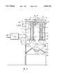
- FIG. 1is a profile perspective view of a schematic of the invention in an electrostatic gun arranged for receiving and charging a measured laminar flow of sorbent particles and for discharging the charged sorbent particles into a polluted gas stream that is shown connected to an electrostatic precipitator having three sections;
- FIG. 2is a profile sectional view of a bag house arrangement that is shown connected to receive a combined flow of charged sorbent pollution particulates and is for removing agglomerized particles from the flow or stream and venting cleaned gas to atmosphere;
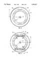
- FIG. 3is a profile perspective schematic view of a cell of a two stage electrostatic precipitator like that shown in FIG. 1;
- FIG. 4is an enlarged side elevation view of the electrostatic gun of FIG. 1, with a section removed from a rear portion of a housing thereof exposing an insulator that is coupled to a high voltage source and showing a barrel rear section with a forward portion and with a charging wand and grounding collar fitted in the barrel, that are shown in broken lines;
- FIG. 5is an enlarged sides elevation view of the grounding collar of FIG. 4;
- FIG. 6is a cross sectional view taken along the line 6--6 of FIG. 4, showing a cross section of a discharge barrel end of the electrostatic gun;
- FIG. 7is a view taken along the line 7--7 of FIG. 4, showing a spider mount arranged across the electrostatic gun straight barrel with a forward end of the charging wand fitted thereto;
- FIG. 7Ais an enlarged sectional view taken within the line 7A--7A of FIG. 4, showing a portion of the charging wand opposite to the grounding ring inner surface as having been enlarged adjacent to the charging wand end that is connected into the spider mount;
- FIG. 8is an enlarged cross sectional view taken within line 8--8 of FIG. 4 showing the grounding ring maintained in the electrostatic gun barrel with the charging wand centered therein;
- FIG. 9is a view like that of FIG. 8 only showing a pair of spaced parallel grounding plates maintained in the electrostatic gun barrel, replacing the grounding ring, and showing the charging wand centered between the charging plates.
- FIG. 1shows a profile perspective view of a schematic representation of the present invention in an electrostatic gun or dry sorbent injection gun 10 of the invention, hereinafter referred to as gun.
- gunShown also in FIG. 1 is a system for removing particulate matter and gaseous pollutants from a flue gas stream, identified as arrow A, that is shown flowing into a tube 11.
- the gun 10is shown to include a sorbent discharge line 12 that connects into the tube 11 to pass a measured laminar flow of charged sorbent particles, under pressure, for mixing in the flue gas stream. The flow of air and sorbent materials pass through and are charged in the gun 10 for dispersion into the polluted gas stream.
- the sorbent particleswill receive, over their surfaces, a like charge, repelling one another and are thereby rapidly dispersed in the flue gas stream.
- a large electrostatically charged areais provided that attracts and interacts with the pollution particles in the flue gas stream to both charge the individual pollution particles and to agglomerize with them.
- the charged and agglomerized particlesthen travel to a particulate removal apparatus like, for example, the pollution control apparatus set out in U.S. Pat. No. 5,308,590 that is also shown in use in a method patent, U.S. Pat. No. 5,332,562; or can involve an electrostatic precipitator 13, like that shown in FIG. 1; or a bag house 30 arrangement, like that shown in FIG. 2, or the like.
- the gun 10 of the present inventionis preferably for use in a system for the remediation and elimination of pollutants in a flue gas stream.
- a systemfor the remediation and elimination of pollutants in a flue gas stream.
- Such systemincludes a hopper system 14 that provides a sorbent hopper 15, a mass flow feed 16, and a blower 17.
- the hopper system 14provides for passing a measured volume of sorbent materials under a pressure that has been generated by an air flow from blower 17 to provide a laminar flow.
- the flowis adjusted to contain a maximum volume of sorbent material for a minimum air content of the sorbent material as is selected for the particular flue gas pollutants to be remediated.
- Which sorbent material selectionconsiders the sorbent particle density and their hydroscopic properties for the chemical pollutants to be removed and takes into account that the chemical reaction rate of the sorbent and pollution particles is a surface phenomena. Which sorbent feed rate is further determined from a consideration of the stoichiometric properties of the pollutants and those of the sorbent compound.
- the laminar flow of sorbent materialsis passed through a line 18 to travel through the gun 10 wherein the individual sorbent material particles are electrostatically charged.
- the charged sorbent particlesare then injected into a polluted flue gas stream, arrow A in FIG. 1, that then travels to the apparatus for the removal of agglomerized sorbent and pollution particles from that gas stream.
- a high voltage power supplyshown as block 19, is operated by controller 20, to pass a high voltage through wires 21, shown as a single wire, to the gun 10.
- the controller 20may also be used to provide power through wires 55a and 55b to grounding ring 95, as set out below, that is provided for an enhancement effect to a corona discharge that is formed around a charging wand 70, as set out in detail hereinbelow.
- FIG. 1An apparatus for removing charged sorbent and pollution particles, is shown in FIG. 1 as an electrostatic precipitator 13 that will provide for removal of essentially all pollution particles and gases in a polluted gas stream.
- the electrostatic precipitator of FIG. 1is illustrated as including a plurality of transformer-rectifier sections 22 that are maintained on a top of the unit. Which sections 22 are for supplying power to a number of discharge and collection electrodes to generate a strong field between which plates. Contaminated gases are passed through the field between the plates and a unipolar discharge of gas ions from the discharge electrode will then attach itself to the particles to be collected. This unipolar discharge of gas ions, generally at a negative charge, is brought about at certain critical voltages where air molecules become ionized.
- the gun 10 the inventionprovides for a charging of sorbent particles by their passage through a corona and for their injection into the gas stream, to form a charged area within the tube 11 to both charge the pollution particles in the gas stream and to agglomerize with them. Accordingly, the charged and combined pollution and sorbent particles that pass into an inlet 23 of the electrostatic precipitator 13 are already charged and only minimum power, if any, is required to further charge them.
- FIG. 3shows an example of a two stage precipitator 24 that may be utilized as a component of the electrostatic precipitator 13.
- a dirty gas flowarrow B, passes through spaced apart tubes 25a and 25b, as a pre-ionizing stage.
- the outer tubes 25aconnect through pre-ionizing wires 26 with the center tube 25b shown connected to a ground 27.
- a potential voltagethereby exists between adjacent tubes 25a and 25b that provide for particle charging.
- Which collector plate charging and dischargingprovides for attracting and releasing the charged gas particles, removing them from the gas stream that can then be vented, as clean gas, to atmosphere.
- an electrostatic precipitator and its functioningshould be taken as being for example only of a device or system that is suitable for use with the invention for the removal of charged sorbent and pollution particles from a gas stream.
- Charged particle removalcan also be provided by a moving bed system like that shown in the above cited U.S. Pat. Nos. 5,308,590 and 5,332,562 of two of the present inventors. Additional to the moving bed system of the above cited U.S. Patents and the electrostatic precipitator, the charged sorbent and pollution particles can also, for example, be removed utilizing a bag house 30 arrangement like that shown in FIG. 2.
- FIG. 2illustrates bag house 30 connected to receive the combined laminar flow of charged sorbent and flue gas pollution particles from a charged dry sorbent injection gun (CDSI) 31, that is preferably essentially the same as the electrostatic gun 10 and its components of FIG. 1. Shown in FIG. 2, the combined flue gas stream and charge particle flow passes through pipe 32 into the bag house 30. In this arrangement, the charged sorbent and pollution particles have agglomerized to form particles of a size to be conveniently removed during passage of the gas stream through the pours or openings in bags arranged in the bag house.
- CDSIcharged dry sorbent injection gun
- the bag house 30includes a body having a rectangular shape formed from side walls 33, that are closed over by a top 34 and is open across a bottom end 35.
- the charge agglomerized particle contained in the air streamshown as arrows B in FIG. 2, pass through the a tube end 32a that connects through a side wall 33 into the bag house 30.
- Which bag house 30preferably contains a number of cells that are like that described below.
- the air stream that passes into the house bodyimmediately impacts a baffle plate 36 of each cell. In that impact, heavier particles are dislodged from the gas stream and fall through the open area 35 and into a particle catchment basin 43 that is shown as having a funnel shape. Wall or walls of the catchment basin 43 slope inwardly into a neck 44, and a mass of agglomerized particles 45 are shown collected in that neck area to pass therefrom for disposal or processing.
- the particles remaining in the gas streamare removed by passage of the gas stream through bags that are maintained parallel in the bag house between a base plate 38 and top plate 39.
- the base plate 38provides for mounting an open neck end 37a of each bag 37, to where the gas stream B that has traveled around the baffle plate 36 lower end, passes into each bag open neck end 37a.
- the gas stream Btravels up and along each bag 37 to a closed top end 37b, venting through pores of the gas bag and depositing the agglomerized particles along the inner surface of each bag.
- the gas streamis thereby cleaned of its particle content and passes through the bags, as clean gas stream C, and travels into an exhaust line 40 that connects to a stack, not shown, for venting to atmosphere.
- a bag shaking systemis preferably included with bag house 30 to facilitate removal of the agglomerized particles as are captured on each bag 37 inner surface.
- the bag shaking systempreferably includes an electric motor 41 that is mounted between brackets 42 that connect to the top plate 39.
- a motor 41 output shaft, not shown,connects through an eccentric, not shown, that is maintained to a mounting block 42a, that, in turn, is rigidly secured to the bag house body. With a turning of the motor 41 drive shaft and eccentric, the motor and brackets 42 are moved, eccentrically to vigorously shake, the top plate 39 and connected closed bag ends 37b. The collected particles are thereby shaken off from the bag interior surface and fall out of the bag open lower ends 37a.
- the displaced particles that fall out of bags 37travel into the catchment basin 43 and mix with the particles that had fallen out of the gas stream B when it contacted baffle plate 36. Thereafter, the particles travel down the catchment basin 43 inwardly sloping walls to nozzle end or neck 44 and collect into pile 45.
- FIG. 1shows the gun 10 supported to the tube 11 by chains 10a that are each connected, at a top, link through an eyelet 50, as shown best in FIG. 4.
- the eyelets 50are secured to extend outwardly at approximately right angles from spaced points along a top edge of rear and forward gun housings 51 and 52, respectively.
- the rear gun housing 51receives a power cable 21 through an end cap 56 of rear housing 51, shown in FIG. 4, that extends from the H. V. power supply 19 whose electrical output is controlled by controller 20.
- the forward housing 52connects to line 18 through a sorbet inlet tube 53, shown in broken lines in FIG. 4, that is maintained axially in a tube housing 54.
- the hopper systemfeeds a measured flow of dry sorbent material, under pressure to provide a laminar flow of sorbent particles into the gun 10.
- the respective hopper system, H. V. power supply and controllerare preferably like the respective sorbent feed and power supply arrangements that were set out in the earlier patent of two of the inventors U.S. Pat. No. 5,312,598. Accordingly, hopper system 14 and H. V. power supply 19 and controller 20 will not be further discussed herein, it being understood, that the preferred apparatus and its functioning, have been fully described in which earlier patent, and is here included by this reference.
- More than one gun 10can be utilized to charge sorbent flows, and the high voltage power supplied to each gun 10 can be adjustable so as fully charge all the particles in that sorbent material flow.
- Which sorbent material flowis pressurized, preferably by a blower whose air flow output can be varied, to provide for flow rate that is adjustable over a wide range of flow rates to provide air under pressure to produce a laminar flow of air and sorbent materials for injection into the gun 10 for charging and injection into and dispersed within the polluted gas stream.
- Which particulate chargingit should however be understood, due to the gun 10 improvements discussed hereinbelow, will require less electrical power and is more efficient than earlier charging gun arrangements and provides for essentially charging of all sorbent particles as pass through the gun 10. Accordingly, the gun 10 of the invention, it should be understood, is suitable for use for removing pollution particulates from a number of different polluted flue gas streams.
- the gun 10includes the rear and forward housings 51 and 52 each of which may include an eyelet 50 secured thereto, for connection to ends of mounting chains 10a whose other ends connect to the tube 11 mounting the gun 10 thereto, shown in FIG. 1, or other mounting arrangement can be employed within the scope of this disclosure.
- an additional pair of wires 55a and 55bconnect the controller 20 to an a grounding collar or ring or a grounding plate system to provide power thereto that has a different charge than the power passed through cable 21, or a battery may be utilized to provide this function, as set out in detail below.
- the gun 10receives a measured laminar flow of dry sorbent materials from hopper system 14, to react with the particular pollutants as are contained in the polluted flue gas flow or stream illustrated as arrow A in FIG. 1.
- fine particulate limeare selected that are suitable for the removal of pollutants from a flue gas stream emitted by coke ovens, stinter plants or steel-making furnaces.
- a selected sorbent materialmay be nacholite that will react with sulfur dioxide in the gas stream to form sodium sulfate that adheres to the sorbent particles.
- the selected dry sorbent materialsare reduced to fine particles before loading into the hopper system 14 for passage to the gun 10.
- the capacity of the sorbent hopper 15 of the hopper system 14is selected to provide a dry sorbent material laminar flow into the gun 10, as required.
- the flow rateis selected to provide sufficient charged sorbent particles that are dispersed into the polluted gas stream to fully charge and attract all the pollution particulates in that flue gas stream.
- a sorbent hopper 15 capacity of one (1) to several thousand cubic feetis appropriate for the invention.
- Dry sorbent materialsare preferably gravity fed from sorbent hopper 15 into the mass flow fed 16 that measures a volume of dry sorbent materials and moves it through a discharge nozzle, not shown, for transfer through line 18 by operation of blower 17.
- a regenerative blowerthat is capable of providing a variable and closely controlled output volume of pressurized air is suitable for use as blower 17. Such regenerative blowers are in common use.
- the volume of sorbent particle directed into gun 10can be provided by either a volumetric feed system or a loss-in-weight system. Where a very accurate volume of the dry sorbent materials is required, the more accurate loss-in-weight system is preferred.
- Some such feeder systemare currently manufactured as for example, by AccuRate, Inc., by Vibra Screw, Inc., by KTron, Inc., by AutoWeight, Inc., and others. The selection of a particular feed system for use with gun 10 is dependant upon its capabilities for meeting the need to provide a required flow of dry sorbent materials for the particular makeup of the flue gas stream.
- Air under pressure and sorbent materials mixingpreferably takes place in a venturi throat located upstream from line 18, not shown, wherein is provided a velocity increase for thoroughly mixing the dry sorbent materials and air, into a pressurized laminar flow.
- a flow of dry sorbent materials entrained in airis maintained at a pressure of from one (1) to ten (10) PSI during passage through line 18 and into the sorbent injection tube or sorbent inlet tube 53, as shown in FIG. 4.
- Gun 10as shown in FIG. 4, includes, as its rear end, the rear housing 51, that is shown as a cylinder having an open interior. It should, however, be understood, rear housing 51 may be square or rectangular or other shape within the scope of this disclosure.
- the end cap 56is arranged for fitting across an open rear end of rear housing 51, wherethrough the cable 21 is fitted.
- a cable 21 end 21ashown in broken lines, connects to a fitting 57, that is also shown in broken lines.
- the fitting 57is fitted through a rod coupling end 58 that is secured to a rear end 59a of a power transfer rod 59.
- the power transfer rod 59is fitted axially through an insulator 60 that connects to a mounting collar 61 on a forward end.
- the insulator mounting collar 61is a rear end of a barrel insulator section 62 that is fitted through a hole formed through approximately the center of a forward plate 63 and is secured to a forward end of the rear cylindrical housing 51.
- the barrel insulator section 62includes a right angle flange 64 secured therearound.
- the right angle flange 64is fitted and secured onto a forward face of the forward plate 63 with fasteners 65 fitted therethrough that are turned through threaded holes 66 formed through the forward plate 63. So arranged, the barrel insulator section 62 is maintained to the insulator 60 forward end and, connects to the forward plate 63.
- a rear end edge 52a of the forward housingis secured to the forward plate 63 edge, as by a ring clamp arrangement, or the like, not shown, thereby aligning and connecting the respective edges into the gun 10 housing.
- a ceramic base 67is maintained axially within the barrel insulator section 62 and includes a forward end section of the power transfer rod 59 that extends therethrough and ends in a power transfer rod end 59b.
- the power transfer rod end 59bis fitted into a rear end of a wand coupling 68, shown in broken lines.
- the wand coupling 68is preferably formed from flat opposing sections that are coupled together as by fitting fasteners 69 through each, clamping the components together over both the power transfer rod end 59b and a rear end 70a of a charging wand 70. So arranged the changing wand end 70a is electrically connected to the power transfer rod end 59b, passing voltage from the high voltage power supply 19 thereto.
- the charging wand 70is preferably contained within an insulative sleeve 70c from a rear end 71a to a forward section and is maintained axially in a barrel 71, of gun 10, that is shown in broken lines as a straight cylinder, that is open therethrough.
- a rear end 71a of barrel 71is maintained in a sleeve 72 that includes rear and forward coupling collars 73a and 73b.
- the coupling collarsare for fitting, respectively, to a forward end of the insulator section 62 and rear end 71a of the barrel 71.
- the sleeve 72further includes a sorbent flow tube 74 that is fitted at an angle less that ninety (90) degrees, into the sleeve side and includes a collar 74a.
- the collar 74ais for coupling to a forward end of the sorbent injection tube 53 that is contained within tube housing 54.
- Which tube housing 54is secured into the side of the forward housing and to a coupling plate 75 that has a threaded center fitting 76 extending at a right angle out from the center thereof that is for connecting to a sorbent inlet fitting 77.
- the coupling plate 75fits across a forward face of a tube housing plate 78 that is arranged across a lower end of tube housing 54.
- the coupling plate 75 and tube housing plate 78are fitted and maintained together by passing bolts 79 through aligned holes formed through the plates and turning nuts 80 thereover. So arranged, the line 18, wherethrough is passed the measured flow laminar of sorbent materials under pressure, is connected to pass the flow of sorbent particles into the barrel 71 to travel therein alongside the insulative sleeve 70c to the exposed charging wand 70 forward end.
- the barrel 71is preferably smooth walled therealong to where a grounding ring 95 is arranged in a forward barrel 71 end, as discussed hereinbelow.
- the laminar flow of the mix of air and sorbent particlesflows alongside the insulated charging wand 70, shown in broken lines, extending longitudinally in the barrel center, that, as required, may not be insulated, to the uninsulated forward section of the wand that is immediately opposite to the grounding ring 95.
- Such insulative covering sleeve 70cis preferred for minimizing electrical losses.
- the barrel 71 forward end 71bis shown maintained to a coupling fitting 81, shown in broken lines, that connects to an angled barrel forward end 82 that mounts to a barrel discharge 83. It should, however, be understood that another discharge arrangement could be so used within the scope of this disclosure, and that the barrel discharge may connect directly into the tube 11 to essentially discharge the charged sorbent particles directly into the flue gas flow or the like.
- a connecting line arrangementis shown as an angled forward housing section 84, that contains the angled barrel forward end 82, and terminates in a flange 85 whose forward face is fitted to a rear face of a flange 86 that is a rear end of a bell shaped end 88 of a sorbent feed nozzle 87, such arrangement may be dispensed with, and a different coupling arrangement utilized within the scope of this disclosure.
- the bell end 88includes a cone shaped wall that slopes into, to form, the sorbent discharge line 12, as shown also in FIG. 1. Shown in FIG. 4, to maintain the flanges 85 and 86 fitted together, spaced aligned holes are formed through the flanges to receive bolts 89 fitted therethrough that receive nuts 90 turned thereon, coupling the flanges together.
- the smooth walled barrel 71contains the charging wand 70, that extends the length thereof, but is preferably insulated, by insulative sleeve 70c, along its length to a forward end section, which sleeve 70c may be a non-conductive coating, such as a plastic or ceramic material, with the charging wand rear end 70a connected into coupling 68.
- the smooth walled barrel 71can be formed of a P.V.C. type plastic, silicon rubber, ceramic, or like material that is not electrically conductive.
- the charging wand 70is to provide a high voltage corona discharge therearound that will impart a like strong electrostatic charge onto each of the sorbent particles that pass through the barrel 71. Accordingly, for the invention to accommodate, and fully charge all the sorbent particles entrained in the flow of sorbent materials through barrel 71, the voltage passed to the charging wand 70 is preferably variable. To provide for varying the voltage to charging wand 70, as shown in FIG. 1, controller 20 is connected to a high voltage power supply 19 to enable an operator, at the controller 20 to set a voltage for a particle sorbent flow, of up to 100,000 volts at a current of up to 0.05 milli-amps.
- the power requirements of the present invention, as set out below,are significantly reduced over earlier systems due to a corona enhancement arrangement of the invention that includes the grounding ring or collar 95 or opposing grounding plates 101, as set out below.
- the controller 20, as shown in FIG. 1,is preferably a control panel where an operator, not shown, can set a required voltage as an output to the charging wand 70 to produce a corona effect therearound, that is enhanced by the grounding ring 95 or opposing grounding plates 101.
- the smooth walled barrel 71is preferably arranged to be removable and replaceable to accommodate different sorbent flow rates.
- the inventionhas employed, in one model, a two (2) inch diameter barrel capable of conveying, as a laminar flow, from one hundred fifty (150) to three hundred (300) cubic feet per minute of combined air and dry powered sorbent material.
- Another model of gun 10has utilized a three (3) inch diameter barrel that is capable of conveying, as a laminar flow, three hundred (300) to five hundred (500) cubic feet per minute of combined air and dry powered sorbent material. It should, however, be understood that other appropriate diameters of barrels 71 could be so employed within the scope of this disclosure.
- the barrelcan be a metal, ceramic, P.V.C. type plastic, or the like.
- the sorbent inlet tube 53is connected into barrel 71 at an angle less than ninety (90) degrees and is preferably approximately thirty (30) degrees, and is fitted into the side of barrel 71.
- the sorbent particlesare transferred at a pressure of approximately 1 to 5 psi, providing a laminar flow of air and sorbent material that passes through sorbent inlet tube 53 that has an approximate diameter of 2 to 3 inches.
- the flowtravels into and through the barrel 71 that contains the charging wand 70 maintained longitudinally therein.
- the high voltage supplied to charging wand 70is controlled to maintain a uniform high voltage corona discharge therearound.
- the dischargemay be formed along the entire wand length where the insulative sleeve 70c is not in place, it is preferably generated at a location immediately opposite to the grounding ring or collar 95 so as to extend across the barrel towards the charging collar 95 to negatively or positively charge the surface of each sorbent particle that passes therethrough.
- the charging wand 70is preferably insulated along its length to opposite to the grounding ring 95, and, to also provide for improvements in corona discharge generation and avoid arching, the opposing charging wand 70 and grounding ring 95 surfaces are preferably roughened.
- a ratio of the grounding ring 95 diameter to that of the charging wand 70should be greater than approximately 2.7 and is preferably approximately 3.7.
- the diameter of the section or portion of the charging wand 70 that is opposite to the grounding ring 95may be increased to form a ridge 70d extending or projecting outwardly from the charging wand 70 surface and formed therearound to provide a desired ratio of grounding collar and charging wand diameters.
- the controller 20is shown in FIGS. 1, 4 and 5 connected to the grounding ring 95, it should be understood that power can be supplied to which grounding ring from a battery source that is connected thereto, providing a wireless arrangement. Which controller or battery voltage is preferably adjustable.
- the charged sorbent particlesare then discharged into the tube 11 that contains the flue gas flow or stream, arrow A.
- the sorbent particlesthat all bear the same negative or positive charge, tend to repel one another so as to be rapidly dispersed throughout that flue gas stream.
- a utilization, as is preferred in a practice of the invention, of very fine-grained sorbent particlestends to significantly increase the sorbent particles total surface area and considerably reduces the residence time required for their complete dispersion into the polluted gas stream.
- the charged particlesthemselves tend to attract both submicron and larger particulates in the flue gas stream, agglomerating with them to form larger particles of a size to be conveniently removed, cleaning the flow.
- the charged sorbent particlesalso provide for chemically reacting with pollutants in the stream and forming a large area for charging particulates that are not already agglomerated.
- the flue gas stream with entrained sorbentis then directed into a collection system 13, as discussed hereinabove.
- a single electrostatic gun 10may be sufficient to provide a required flow of electrostatically charged sorbent particles into that gas stream so as to fully charge of all the particulates in that flow, including submicron size particulates. Where such single electrostatic gun 10 is not sufficient to supply a required sorbent output. Even taking into account a capability for increasing or decreasing system capacity, a selection of an appropriate size of barrel 71 and controlling of the voltage transmitted to the charging wand 70 more than one gun 10 may be required. Accordingly, the invention can include, within the scope of this disclosure, a second, third of more guns 10, each functioning as described above. Which such second and additional guns 10 are preferably identical to the described gun 10.
- the grounding ring 95is preferably formed of an electrically conductive material and is insulated from the barrel 71.
- the charge received at which grounding ring 95is less than that transmitted to the charging wand 70 and can be either positive or negative so long as it is an opposite charge to that of the charge of the voltage that is transmitted to the charging wand 70. Accordingly, the high voltage present in the charging wand 70 will tend to be attracted to the grounding ring 95. This attraction tends to enhance the creation of a corona effect at a lesser power requirement than for guns without grounding rings.
- FIG. 5shows the wires 55a and 55b as contained in a single cable and connect, respectively, to a grounded sheath 96, that is contained in which cable and to a connector 97, that is maintained to the grounding ring 95.
- a grounded sheath 96that is contained in which cable and to a connector 97, that is maintained to the grounding ring 95.
- bolts 98 with nuts 99 turned thereoverare provided, that receive insulative washers 100 fitted therebetween for isolating the grounding ring 95 from the barrel 71, as set out above.
- FIG. 8shows a cross section of the grounding ring 95 with the charging wand 70 end section shown positioned in the center thereof.
- FIG. 9illustrates another embodiment of grounding plates 101 as an additional arrangement for providing electrically attractive surfaces to promote formation of a corona discharge around charging wand 70.
- the grounding plates 101function like the grounding ring 95, as described above.
- the grounding platesare like parallel plates 101 that are mounted in the barrel 71 with the charging wand 70 centered therebetween. Preferably, each plate is maintained at the same distance identified as C from the charging wand. Which distance C is computed by an analysis of surface area relationships set out above for the grounding ring and charging wand radiuses.
- the opposing parallel plates 101are each connected to wires 55a and 55b to pass a voltage thereto from the controller 20, or can be connected to a battery source.
- the grounding platesfunction like the grounding ring 95 for promoting the formation of a corona discharge around charging wand 70, except that the area across the opposing plate ends is open and so the corona discharge, as it extends towards which plates, includes lesser charged areas in the areas of the plate 101 ends.
- the plates 101may be curved to close the distances between their ends, not shown, to overcome this deficiency and are preferably electrically insulated from the barrel 71 as by an inclusion of non-conductive spacers 102 positioned therebetween, or the like. Or, where the barrel itself is formed from a non-conductive material, spacers 102 may not be needed. Except as set out above, the opposing parallel plates 101 essentially function like the grounding ring 95.
- grounding surfacesidentified as grounding ring 95 and opposing grounding plates 101, are set out and described above, it should be understood that other arrangements for providing electrically attractive surfaces within the barrel 71, for promoting the formation of a corona around charging wand 70, are possible within the scope of this disclosure.
- the inventionalso preferably includes an arrangement for maintaining the charging wand 70 centered in the barrel 71, at the desired distance from the grounding surface or surfaces arranged therein.
- the charging wand 70is, as set out above, maintained at its rear end 70a by the coupling 68.
- the charging wand end 70bis preferably fitted into a center cup or cylinder 106 of a spider 105, as shown in FIG. 7.
- the spider 105is shown as flat, and is arranged to be fitted across the barrel.
- the charging wand endis shown maintained in the spider cup or cylinder 106 by turning a set screw 107 thereagainst, that is threaded and turned through a threaded hole formed through the cup or cylinder wall, into engagement with the side of the charging wand end 70b, securing it therein.
- a number of straight radial members 108extend outwardly at spaced intervals from around the center cup or cylinder 106.
- the radial members 108connect into a ring 109 that is fitted into and is secured across the barrel 71 interior, perpendicular to the barrel 71 inner wall.
- the spider 105is preferably formed from a non-conductive material. Also, as a high volume flow of sorbent particles is to be directed through the open areas between the spider radial members, it is preferred that the spider 105 be formed of a strong durable material, such as a ceramic.
- a laminar flow of charged sorbent particlespasses through the spider 105 and, for the arrangement shown in FIG. 4, is directed through the barrel angled end 82 to flow into a bell end of the sorbent feed nozzle 87 that narrows into the sorbent discharge tube 12.
- narrowingthe velocity of the sorbent particle flow increases, thereby increasing the corrosive effects of the particles on a surface whereover they pass.
- the charged sorbent particlesafter passage through the sorbent discharge tube 12, the charged sorbent particles, under pressure, travel into and are thoroughly mixed into the gas stream, arrow A.
- the agglomerized and charged sorbent and pollution particlestravel through tube 11 and into an apparatus 13 for removal.
Landscapes
- Chemical & Material Sciences (AREA)
- Chemical Kinetics & Catalysis (AREA)
- General Chemical & Material Sciences (AREA)
- Electrostatic Separation (AREA)
Abstract
Description
Claims (17)
Priority Applications (1)
| Application Number | Priority Date | Filing Date | Title |
|---|---|---|---|
| US08/429,082US5591412A (en) | 1995-04-26 | 1995-04-26 | Electrostatic gun for injection of an electrostatically charged sorbent into a polluted gas stream |
Applications Claiming Priority (1)
| Application Number | Priority Date | Filing Date | Title |
|---|---|---|---|
| US08/429,082US5591412A (en) | 1995-04-26 | 1995-04-26 | Electrostatic gun for injection of an electrostatically charged sorbent into a polluted gas stream |
Publications (1)
| Publication Number | Publication Date |
|---|---|
| US5591412Atrue US5591412A (en) | 1997-01-07 |
Family
ID=23701716
Family Applications (1)
| Application Number | Title | Priority Date | Filing Date |
|---|---|---|---|
| US08/429,082Expired - Fee RelatedUS5591412A (en) | 1995-04-26 | 1995-04-26 | Electrostatic gun for injection of an electrostatically charged sorbent into a polluted gas stream |
Country Status (1)
| Country | Link |
|---|---|
| US (1) | US5591412A (en) |
Cited By (58)
| Publication number | Priority date | Publication date | Assignee | Title |
|---|---|---|---|---|
| US5795367A (en)* | 1996-06-25 | 1998-08-18 | Jack Kennedy Metal Products & Buildings, Inc. | Method of and apparatus for reducing sulfur in combustion gases |
| US5827352A (en)* | 1997-04-16 | 1998-10-27 | Electric Power Research Institute, Inc. | Method for removing mercury from a gas stream and apparatus for same |
| US6030506A (en)* | 1997-09-16 | 2000-02-29 | Thermo Power Corporation | Preparation of independently generated highly reactive chemical species |
| US6152988A (en)* | 1997-10-22 | 2000-11-28 | The United States Of America As Represented By The Administrator Of The Environmental Protection Agency | Enhancement of electrostatic precipitation with precharged particles and electrostatic field augmented fabric filtration |
| US6170668B1 (en)* | 1998-05-01 | 2001-01-09 | Mse Technology Applications, Inc. | Apparatus for extraction of contaminants from a gas |
| US20020122751A1 (en)* | 1998-11-05 | 2002-09-05 | Sinaiko Robert J. | Electro-kinetic air transporter-conditioner devices with a enhanced collector electrode for collecting more particulate matter |
| US20020150520A1 (en)* | 1998-11-05 | 2002-10-17 | Taylor Charles E. | Electro-kinetic air transporter-conditioner devices with enhanced emitter electrode |
| US20030147786A1 (en)* | 2001-01-29 | 2003-08-07 | Taylor Charles E. | Air transporter-conditioner device with tubular electrode configurations |
| US20040018126A1 (en)* | 1998-11-05 | 2004-01-29 | Lau Shek Fai | Electrode self-cleaning mechanism for electro-kinetic air transporter-conditioner devices |
| US20040096376A1 (en)* | 1998-11-05 | 2004-05-20 | Sharper Image Corporation | Electro-kinetic air transporter-conditioner |
| US20040202547A1 (en)* | 2003-04-09 | 2004-10-14 | Sharper Image Corporation | Air transporter-conditioner with particulate detection |
| US20040206236A1 (en)* | 2003-04-17 | 2004-10-21 | Aradi Allen A. | Use of manganese compounds to improve the efficiency of and reduce back-corona discharge on electrostatic precipitators |
| US20040226447A1 (en)* | 2003-05-14 | 2004-11-18 | Sharper Image Corporation | Electrode self-cleaning mechanisms with anti-arc guard for electro-kinetic air transporter-conditioner devices |
| US20050051028A1 (en)* | 2003-09-05 | 2005-03-10 | Sharper Image Corporation | Electrostatic precipitators with insulated driver electrodes |
| US20050051420A1 (en)* | 2003-09-05 | 2005-03-10 | Sharper Image Corporation | Electro-kinetic air transporter and conditioner devices with insulated driver electrodes |
| US20050095182A1 (en)* | 2003-09-19 | 2005-05-05 | Sharper Image Corporation | Electro-kinetic air transporter-conditioner devices with electrically conductive foam emitter electrode |
| US20050132880A1 (en)* | 2003-12-17 | 2005-06-23 | Ramsay Chang | Method and apparatus for removing particulate and vapor phase contaminants from a gas stream |
| US20050163669A1 (en)* | 1998-11-05 | 2005-07-28 | Sharper Image Corporation | Air conditioner devices including safety features |
| US20050183576A1 (en)* | 1998-11-05 | 2005-08-25 | Sharper Image Corporation | Electro-kinetic air transporter conditioner device with enhanced anti-microorganism capability and variable fan assist |
| US20050194583A1 (en)* | 2004-03-02 | 2005-09-08 | Sharper Image Corporation | Air conditioner device including pin-ring electrode configurations with driver electrode |
| US20050194246A1 (en)* | 2004-03-02 | 2005-09-08 | Sharper Image Corporation | Electro-kinetic air transporter and conditioner devices including pin-ring electrode configurations with driver electrode |
| US20050199125A1 (en)* | 2004-02-18 | 2005-09-15 | Sharper Image Corporation | Air transporter and/or conditioner device with features for cleaning emitter electrodes |
| US20050210902A1 (en)* | 2004-02-18 | 2005-09-29 | Sharper Image Corporation | Electro-kinetic air transporter and/or conditioner devices with features for cleaning emitter electrodes |
| US20050238551A1 (en)* | 2003-12-11 | 2005-10-27 | Sharper Image Corporation | Electro-kinetic air transporter-conditioner system and method to oxidize volatile organic compounds |
| US20050279905A1 (en)* | 2004-02-18 | 2005-12-22 | Sharper Image Corporation | Air movement device with a quick assembly base |
| US20060016337A1 (en)* | 2004-07-23 | 2006-01-26 | Sharper Image Corporation | Air conditioner device with enhanced ion output production features |
| US20060016336A1 (en)* | 2004-07-23 | 2006-01-26 | Sharper Image Corporation | Air conditioner device with variable voltage controlled trailing electrodes |
| US20060018809A1 (en)* | 2004-07-23 | 2006-01-26 | Sharper Image Corporation | Air conditioner device with removable driver electrodes |
| US20060018812A1 (en)* | 2004-03-02 | 2006-01-26 | Taylor Charles E | Air conditioner devices including pin-ring electrode configurations with driver electrode |
| US20060018807A1 (en)* | 2004-07-23 | 2006-01-26 | Sharper Image Corporation | Air conditioner device with enhanced germicidal lamp |
| US20060018810A1 (en)* | 2004-07-23 | 2006-01-26 | Sharper Image Corporation | Air conditioner device with 3/2 configuration and individually removable driver electrodes |
| US20060021509A1 (en)* | 2004-07-23 | 2006-02-02 | Taylor Charles E | Air conditioner device with individually removable driver electrodes |
| US20060118039A1 (en)* | 2004-11-03 | 2006-06-08 | Cooper Steven C | Spray device with touchless controls |
| US20060124779A1 (en)* | 2004-11-12 | 2006-06-15 | Cooper Steven C | Panel-mounted electrostatic spray nozzle system |
| US20060124780A1 (en)* | 2004-11-12 | 2006-06-15 | Cooper Steven C | Electrostatic spray nozzle with adjustable fluid tip and interchangeable components |
| US20060143936A1 (en)* | 2004-09-27 | 2006-07-06 | Roy Studebaker | Shrouded floor drying fan |
| US20060177592A1 (en)* | 2003-03-18 | 2006-08-10 | Masashi Takebe | Method and device for electrostatic coating |
| WO2006053229A3 (en)* | 2004-11-12 | 2006-11-09 | Mystic Tan Inc | Electrostatic spray nozzle system |
| US20070009406A1 (en)* | 1998-11-05 | 2007-01-11 | Sharper Image Corporation | Electrostatic air conditioner devices with enhanced collector electrode |
| US20070041885A1 (en)* | 2005-08-18 | 2007-02-22 | Maziuk John Jr | Method of removing sulfur dioxide from a flue gas stream |
| US20070081936A1 (en)* | 2005-09-15 | 2007-04-12 | Maziuk John Jr | Method of removing sulfur trioxide from a flue gas stream |
| US20070131805A1 (en)* | 2004-02-09 | 2007-06-14 | Matsushita Electric Works, Ltd. | Electrostatic spraying device |
| US20070148061A1 (en)* | 1998-11-05 | 2007-06-28 | The Sharper Image Corporation | Electro-kinetic air transporter and/or air conditioner with devices with features for cleaning emitter electrodes |
| US20070164130A1 (en)* | 2005-10-13 | 2007-07-19 | Cool Clean Technologies, Inc. | Nozzle device and method for forming cryogenic composite fluid spray |
| US20070176029A1 (en)* | 2004-02-09 | 2007-08-02 | Naoki Yamaguchi | Electrostatic spraying device |
| US20070210734A1 (en)* | 2006-02-28 | 2007-09-13 | Sharper Image Corporation | Air treatment apparatus having a voltage control device responsive to current sensing |
| US7695690B2 (en) | 1998-11-05 | 2010-04-13 | Tessera, Inc. | Air treatment apparatus having multiple downstream electrodes |
| US7724492B2 (en) | 2003-09-05 | 2010-05-25 | Tessera, Inc. | Emitter electrode having a strip shape |
| US7906080B1 (en) | 2003-09-05 | 2011-03-15 | Sharper Image Acquisition Llc | Air treatment apparatus having a liquid holder and a bipolar ionization device |
| US7959869B2 (en) | 1998-11-05 | 2011-06-14 | Sharper Image Acquisition Llc | Air treatment apparatus with a circuit operable to sense arcing |
| US9352355B1 (en) | 2012-04-15 | 2016-05-31 | David P. Jackson | Particle-plasma ablation process |
| CN108262165A (en)* | 2018-01-09 | 2018-07-10 | 珠海市万隆达智能科技有限公司 | The Electrostatic Absorption collection device of particle |
| CN108800181A (en)* | 2018-07-24 | 2018-11-13 | 清华大学 | Induce dust-extraction unit, stove induction cleaner and stove |
| US10369506B1 (en) | 2018-11-19 | 2019-08-06 | Physician Electronic Networks LLC | System, method, and apparatus to reduce urban air pollution |
| US10639691B1 (en) | 2012-01-05 | 2020-05-05 | David P. Jackson | Method for forming and applying an oxygenated machining fluid |
| US10661287B2 (en) | 2017-04-04 | 2020-05-26 | David P. Jackson | Passive electrostatic CO2 composite spray applicator |
| CN113071349A (en)* | 2021-03-29 | 2021-07-06 | 福建百城新能源科技有限公司 | City fills station soon |
| US11859375B2 (en) | 2009-12-16 | 2024-01-02 | Kohler Co. | Touchless faucet assembly and method of operation |
Citations (14)
| Publication number | Priority date | Publication date | Assignee | Title |
|---|---|---|---|---|
| US4023939A (en)* | 1975-03-05 | 1977-05-17 | Bergwerksverband Gmbh | Method and arrangement for purifying gases |
| US4083701A (en)* | 1975-10-09 | 1978-04-11 | Deutsche Babcock Aktiengesellschaft | Process and apparatus for removing undesirable gases from flue gases |
| US4220478A (en)* | 1978-12-04 | 1980-09-02 | Newbery Energy Corporation | Method for removing particulate matter from a gas stream and a method for producing a product using the removed particulate matter |
| US4254557A (en)* | 1979-07-31 | 1981-03-10 | Exxon Research And Engineering Co. | Magnetically stabilized fluid cross-flow contactor and process for using the same |
| US4290786A (en)* | 1978-12-04 | 1981-09-22 | Ecotech Corporation | Apparatus for removing particulate matter from a gas stream |
| US4604112A (en)* | 1984-10-05 | 1986-08-05 | Westinghouse Electric Corp. | Electrostatic precipitator with readily cleanable collecting electrode |
| US4650647A (en)* | 1984-12-05 | 1987-03-17 | Takuma Co., Ltd. | Apparatus for removing acid constituents from waste-gas |
| US4725290A (en)* | 1986-11-14 | 1988-02-16 | Kernforschungszentrum Karlsruhe Gmbh | Method for the purification of air or gas streams by a multi-path adsorption principle and moving-bed filtering apparatus for performing the method |
| US5044564A (en)* | 1989-11-21 | 1991-09-03 | Sickles James E | Electrostatic spray gun |
| US5167931A (en)* | 1990-03-28 | 1992-12-01 | The Babcock & Wilcox Company | SO2 control using moving granular beds |
| US5308590A (en)* | 1993-06-14 | 1994-05-03 | Alanco Environmental Resources Corp. | Apparatus for removing particulate matter and gases from a polluted gas stream |
| US5312598A (en)* | 1993-08-26 | 1994-05-17 | Alanco Environmental Resource Corp. | Hopper system and electrostatic gun for injection of an electrostatically charged sorbent into a polluted gas stream |
| US5332562A (en)* | 1993-06-18 | 1994-07-26 | Kersey Larry M | Method for removing particulate matter and gases from a polluted gas stream |
| US5344082A (en)* | 1992-10-05 | 1994-09-06 | Nordson Corporation | Tribo-electric powder spray gun |
- 1995
- 1995-04-26USUS08/429,082patent/US5591412A/ennot_activeExpired - Fee Related
Patent Citations (14)
| Publication number | Priority date | Publication date | Assignee | Title |
|---|---|---|---|---|
| US4023939A (en)* | 1975-03-05 | 1977-05-17 | Bergwerksverband Gmbh | Method and arrangement for purifying gases |
| US4083701A (en)* | 1975-10-09 | 1978-04-11 | Deutsche Babcock Aktiengesellschaft | Process and apparatus for removing undesirable gases from flue gases |
| US4220478A (en)* | 1978-12-04 | 1980-09-02 | Newbery Energy Corporation | Method for removing particulate matter from a gas stream and a method for producing a product using the removed particulate matter |
| US4290786A (en)* | 1978-12-04 | 1981-09-22 | Ecotech Corporation | Apparatus for removing particulate matter from a gas stream |
| US4254557A (en)* | 1979-07-31 | 1981-03-10 | Exxon Research And Engineering Co. | Magnetically stabilized fluid cross-flow contactor and process for using the same |
| US4604112A (en)* | 1984-10-05 | 1986-08-05 | Westinghouse Electric Corp. | Electrostatic precipitator with readily cleanable collecting electrode |
| US4650647A (en)* | 1984-12-05 | 1987-03-17 | Takuma Co., Ltd. | Apparatus for removing acid constituents from waste-gas |
| US4725290A (en)* | 1986-11-14 | 1988-02-16 | Kernforschungszentrum Karlsruhe Gmbh | Method for the purification of air or gas streams by a multi-path adsorption principle and moving-bed filtering apparatus for performing the method |
| US5044564A (en)* | 1989-11-21 | 1991-09-03 | Sickles James E | Electrostatic spray gun |
| US5167931A (en)* | 1990-03-28 | 1992-12-01 | The Babcock & Wilcox Company | SO2 control using moving granular beds |
| US5344082A (en)* | 1992-10-05 | 1994-09-06 | Nordson Corporation | Tribo-electric powder spray gun |
| US5308590A (en)* | 1993-06-14 | 1994-05-03 | Alanco Environmental Resources Corp. | Apparatus for removing particulate matter and gases from a polluted gas stream |
| US5332562A (en)* | 1993-06-18 | 1994-07-26 | Kersey Larry M | Method for removing particulate matter and gases from a polluted gas stream |
| US5312598A (en)* | 1993-08-26 | 1994-05-17 | Alanco Environmental Resource Corp. | Hopper system and electrostatic gun for injection of an electrostatically charged sorbent into a polluted gas stream |
Cited By (103)
| Publication number | Priority date | Publication date | Assignee | Title |
|---|---|---|---|---|
| US5795367A (en)* | 1996-06-25 | 1998-08-18 | Jack Kennedy Metal Products & Buildings, Inc. | Method of and apparatus for reducing sulfur in combustion gases |
| US5827352A (en)* | 1997-04-16 | 1998-10-27 | Electric Power Research Institute, Inc. | Method for removing mercury from a gas stream and apparatus for same |
| US6030506A (en)* | 1997-09-16 | 2000-02-29 | Thermo Power Corporation | Preparation of independently generated highly reactive chemical species |
| US6152988A (en)* | 1997-10-22 | 2000-11-28 | The United States Of America As Represented By The Administrator Of The Environmental Protection Agency | Enhancement of electrostatic precipitation with precharged particles and electrostatic field augmented fabric filtration |
| US6170668B1 (en)* | 1998-05-01 | 2001-01-09 | Mse Technology Applications, Inc. | Apparatus for extraction of contaminants from a gas |
| US20050183576A1 (en)* | 1998-11-05 | 2005-08-25 | Sharper Image Corporation | Electro-kinetic air transporter conditioner device with enhanced anti-microorganism capability and variable fan assist |
| US7318856B2 (en) | 1998-11-05 | 2008-01-15 | Sharper Image Corporation | Air treatment apparatus having an electrode extending along an axis which is substantially perpendicular to an air flow path |
| US20050232831A1 (en)* | 1998-11-05 | 2005-10-20 | Sharper Image Corporation | Air conditioner devices |
| USRE41812E1 (en) | 1998-11-05 | 2010-10-12 | Sharper Image Acquisition Llc | Electro-kinetic air transporter-conditioner |
| US20040018126A1 (en)* | 1998-11-05 | 2004-01-29 | Lau Shek Fai | Electrode self-cleaning mechanism for electro-kinetic air transporter-conditioner devices |
| US20040033340A1 (en)* | 1998-11-05 | 2004-02-19 | Sharper Image Corporation | Electrode cleaner for use with electro-kinetic air transporter-conditioner device |
| US20040079233A1 (en)* | 1998-11-05 | 2004-04-29 | Sharper Image Corporation | Electrode self-cleaning mechanism for electro-kinetic air transporter-conditioner devices |
| US20040096376A1 (en)* | 1998-11-05 | 2004-05-20 | Sharper Image Corporation | Electro-kinetic air transporter-conditioner |
| US20070009406A1 (en)* | 1998-11-05 | 2007-01-11 | Sharper Image Corporation | Electrostatic air conditioner devices with enhanced collector electrode |
| US7976615B2 (en) | 1998-11-05 | 2011-07-12 | Tessera, Inc. | Electro-kinetic air mover with upstream focus electrode surfaces |
| US20020150520A1 (en)* | 1998-11-05 | 2002-10-17 | Taylor Charles E. | Electro-kinetic air transporter-conditioner devices with enhanced emitter electrode |
| US7662348B2 (en) | 1998-11-05 | 2010-02-16 | Sharper Image Acquistion LLC | Air conditioner devices |
| US7695690B2 (en) | 1998-11-05 | 2010-04-13 | Tessera, Inc. | Air treatment apparatus having multiple downstream electrodes |
| US20070148061A1 (en)* | 1998-11-05 | 2007-06-28 | The Sharper Image Corporation | Electro-kinetic air transporter and/or air conditioner with devices with features for cleaning emitter electrodes |
| US20100162894A1 (en)* | 1998-11-05 | 2010-07-01 | Tessera, Inc. | Electro-kinetic air mover with upstream focus electrode surfaces |
| US20020122751A1 (en)* | 1998-11-05 | 2002-09-05 | Sinaiko Robert J. | Electro-kinetic air transporter-conditioner devices with a enhanced collector electrode for collecting more particulate matter |
| US8425658B2 (en) | 1998-11-05 | 2013-04-23 | Tessera, Inc. | Electrode cleaning in an electro-kinetic air mover |
| US7959869B2 (en) | 1998-11-05 | 2011-06-14 | Sharper Image Acquisition Llc | Air treatment apparatus with a circuit operable to sense arcing |
| US20050163669A1 (en)* | 1998-11-05 | 2005-07-28 | Sharper Image Corporation | Air conditioner devices including safety features |
| US7517504B2 (en) | 2001-01-29 | 2009-04-14 | Taylor Charles E | Air transporter-conditioner device with tubular electrode configurations |
| US20040170542A1 (en)* | 2001-01-29 | 2004-09-02 | Sharper Image Corporation | Air transporter-conditioner device with tubular electrode configurations |
| US20030159918A1 (en)* | 2001-01-29 | 2003-08-28 | Taylor Charles E. | Apparatus for conditioning air with anti-microorganism capability |
| US20030147786A1 (en)* | 2001-01-29 | 2003-08-07 | Taylor Charles E. | Air transporter-conditioner device with tubular electrode configurations |
| US20060177592A1 (en)* | 2003-03-18 | 2006-08-10 | Masashi Takebe | Method and device for electrostatic coating |
| US7328862B2 (en)* | 2003-03-18 | 2008-02-12 | Honda Motor Co., Ltd. | Method and device for electrostatic coating |
| US20040202547A1 (en)* | 2003-04-09 | 2004-10-14 | Sharper Image Corporation | Air transporter-conditioner with particulate detection |
| US7405672B2 (en) | 2003-04-09 | 2008-07-29 | Sharper Image Corp. | Air treatment device having a sensor |
| US20060219096A1 (en)* | 2003-04-17 | 2006-10-05 | Aradi Allen A | Use of manganese compounds to improve the efficiency of and reduce back-corona discharge on electrostatic precipitators |
| US7094274B2 (en)* | 2003-04-17 | 2006-08-22 | Afton Chemical Intangibles Llc | Use of manganese compounds to improve the efficiency of and reduce back-corona discharge on electrostatic precipitators |
| JP2004314040A (en)* | 2003-04-17 | 2004-11-11 | Ethyl Corp | Method for improving efficiency of electrostatic precipitator and method for reducing back-corona discharge on electrostatic precipitator |
| US20040206236A1 (en)* | 2003-04-17 | 2004-10-21 | Aradi Allen A. | Use of manganese compounds to improve the efficiency of and reduce back-corona discharge on electrostatic precipitators |
| US7220295B2 (en) | 2003-05-14 | 2007-05-22 | Sharper Image Corporation | Electrode self-cleaning mechanisms with anti-arc guard for electro-kinetic air transporter-conditioner devices |
| US20040226447A1 (en)* | 2003-05-14 | 2004-11-18 | Sharper Image Corporation | Electrode self-cleaning mechanisms with anti-arc guard for electro-kinetic air transporter-conditioner devices |
| US7906080B1 (en) | 2003-09-05 | 2011-03-15 | Sharper Image Acquisition Llc | Air treatment apparatus having a liquid holder and a bipolar ionization device |
| US7517505B2 (en) | 2003-09-05 | 2009-04-14 | Sharper Image Acquisition Llc | Electro-kinetic air transporter and conditioner devices with 3/2 configuration having driver electrodes |
| US7724492B2 (en) | 2003-09-05 | 2010-05-25 | Tessera, Inc. | Emitter electrode having a strip shape |
| US20050152818A1 (en)* | 2003-09-05 | 2005-07-14 | Sharper Image Corporation | Electro-kinetic air transporter and conditioner devices with 3/2 configuration having driver electrodes |
| US7077890B2 (en) | 2003-09-05 | 2006-07-18 | Sharper Image Corporation | Electrostatic precipitators with insulated driver electrodes |
| US20050051420A1 (en)* | 2003-09-05 | 2005-03-10 | Sharper Image Corporation | Electro-kinetic air transporter and conditioner devices with insulated driver electrodes |
| US20050051028A1 (en)* | 2003-09-05 | 2005-03-10 | Sharper Image Corporation | Electrostatic precipitators with insulated driver electrodes |
| US20050095182A1 (en)* | 2003-09-19 | 2005-05-05 | Sharper Image Corporation | Electro-kinetic air transporter-conditioner devices with electrically conductive foam emitter electrode |
| US7767169B2 (en) | 2003-12-11 | 2010-08-03 | Sharper Image Acquisition Llc | Electro-kinetic air transporter-conditioner system and method to oxidize volatile organic compounds |
| US20050238551A1 (en)* | 2003-12-11 | 2005-10-27 | Sharper Image Corporation | Electro-kinetic air transporter-conditioner system and method to oxidize volatile organic compounds |
| US7141091B2 (en)* | 2003-12-17 | 2006-11-28 | Electric Power Research Institute, Inc. | Method and apparatus for removing particulate and vapor phase contaminants from a gas stream |
| US20050132880A1 (en)* | 2003-12-17 | 2005-06-23 | Ramsay Chang | Method and apparatus for removing particulate and vapor phase contaminants from a gas stream |
| US20070176029A1 (en)* | 2004-02-09 | 2007-08-02 | Naoki Yamaguchi | Electrostatic spraying device |
| US20070131805A1 (en)* | 2004-02-09 | 2007-06-14 | Matsushita Electric Works, Ltd. | Electrostatic spraying device |
| US7841549B2 (en)* | 2004-02-09 | 2010-11-30 | Panasonic Electric Works Co., Ltd. | Electrostatic spraying device |
| US7823809B2 (en)* | 2004-02-09 | 2010-11-02 | Panasonic Electric Works Co., Ltd. | Electrostatic spraying device |
| US8043573B2 (en) | 2004-02-18 | 2011-10-25 | Tessera, Inc. | Electro-kinetic air transporter with mechanism for emitter electrode travel past cleaning member |
| US20050199125A1 (en)* | 2004-02-18 | 2005-09-15 | Sharper Image Corporation | Air transporter and/or conditioner device with features for cleaning emitter electrodes |
| US20050210902A1 (en)* | 2004-02-18 | 2005-09-29 | Sharper Image Corporation | Electro-kinetic air transporter and/or conditioner devices with features for cleaning emitter electrodes |
| US20050279905A1 (en)* | 2004-02-18 | 2005-12-22 | Sharper Image Corporation | Air movement device with a quick assembly base |
| US20050194583A1 (en)* | 2004-03-02 | 2005-09-08 | Sharper Image Corporation | Air conditioner device including pin-ring electrode configurations with driver electrode |
| US20050194246A1 (en)* | 2004-03-02 | 2005-09-08 | Sharper Image Corporation | Electro-kinetic air transporter and conditioner devices including pin-ring electrode configurations with driver electrode |
| US7517503B2 (en) | 2004-03-02 | 2009-04-14 | Sharper Image Acquisition Llc | Electro-kinetic air transporter and conditioner devices including pin-ring electrode configurations with driver electrode |
| US20060018812A1 (en)* | 2004-03-02 | 2006-01-26 | Taylor Charles E | Air conditioner devices including pin-ring electrode configurations with driver electrode |
| US7638104B2 (en) | 2004-03-02 | 2009-12-29 | Sharper Image Acquisition Llc | Air conditioner device including pin-ring electrode configurations with driver electrode |
| US7311762B2 (en) | 2004-07-23 | 2007-12-25 | Sharper Image Corporation | Air conditioner device with a removable driver electrode |
| US7285155B2 (en) | 2004-07-23 | 2007-10-23 | Taylor Charles E | Air conditioner device with enhanced ion output production features |
| US20060016336A1 (en)* | 2004-07-23 | 2006-01-26 | Sharper Image Corporation | Air conditioner device with variable voltage controlled trailing electrodes |
| US20060018810A1 (en)* | 2004-07-23 | 2006-01-26 | Sharper Image Corporation | Air conditioner device with 3/2 configuration and individually removable driver electrodes |
| US20060018809A1 (en)* | 2004-07-23 | 2006-01-26 | Sharper Image Corporation | Air conditioner device with removable driver electrodes |
| US20060016333A1 (en)* | 2004-07-23 | 2006-01-26 | Sharper Image Corporation | Air conditioner device with removable driver electrodes |
| US20060018807A1 (en)* | 2004-07-23 | 2006-01-26 | Sharper Image Corporation | Air conditioner device with enhanced germicidal lamp |
| US20060021509A1 (en)* | 2004-07-23 | 2006-02-02 | Taylor Charles E | Air conditioner device with individually removable driver electrodes |
| US7897118B2 (en) | 2004-07-23 | 2011-03-01 | Sharper Image Acquisition Llc | Air conditioner device with removable driver electrodes |
| US20060018076A1 (en)* | 2004-07-23 | 2006-01-26 | Sharper Image Corporation | Air conditioner device with removable driver electrodes |
| US20060016337A1 (en)* | 2004-07-23 | 2006-01-26 | Sharper Image Corporation | Air conditioner device with enhanced ion output production features |
| US7291207B2 (en) | 2004-07-23 | 2007-11-06 | Sharper Image Corporation | Air treatment apparatus with attachable grill |
| US7971369B2 (en)* | 2004-09-27 | 2011-07-05 | Roy Studebaker | Shrouded floor drying fan |
| US20060143936A1 (en)* | 2004-09-27 | 2006-07-06 | Roy Studebaker | Shrouded floor drying fan |
| US20060118039A1 (en)* | 2004-11-03 | 2006-06-08 | Cooper Steven C | Spray device with touchless controls |
| WO2006053229A3 (en)* | 2004-11-12 | 2006-11-09 | Mystic Tan Inc | Electrostatic spray nozzle system |
| US20060124780A1 (en)* | 2004-11-12 | 2006-06-15 | Cooper Steven C | Electrostatic spray nozzle with adjustable fluid tip and interchangeable components |
| US7913938B2 (en) | 2004-11-12 | 2011-03-29 | Mystic Tan, Inc. | Electrostatic spray nozzle with adjustable fluid tip and interchangeable components |
| US20060124779A1 (en)* | 2004-11-12 | 2006-06-15 | Cooper Steven C | Panel-mounted electrostatic spray nozzle system |
| US7531154B2 (en) | 2005-08-18 | 2009-05-12 | Solvay Chemicals | Method of removing sulfur dioxide from a flue gas stream |
| US20090241774A1 (en)* | 2005-08-18 | 2009-10-01 | Solvay Chemicals | Method of Removing Sulfur Dioxide From A Flue Gas Stream |
| US20070041885A1 (en)* | 2005-08-18 | 2007-02-22 | Maziuk John Jr | Method of removing sulfur dioxide from a flue gas stream |
| US7854911B2 (en) | 2005-08-18 | 2010-12-21 | Solvay Chemicals, Inc. | Method of removing sulfur dioxide from a flue gas stream |
| US20070081936A1 (en)* | 2005-09-15 | 2007-04-12 | Maziuk John Jr | Method of removing sulfur trioxide from a flue gas stream |
| US7481987B2 (en) | 2005-09-15 | 2009-01-27 | Solvay Chemicals | Method of removing sulfur trioxide from a flue gas stream |
| US20070164130A1 (en)* | 2005-10-13 | 2007-07-19 | Cool Clean Technologies, Inc. | Nozzle device and method for forming cryogenic composite fluid spray |
| US7389941B2 (en) | 2005-10-13 | 2008-06-24 | Cool Clean Technologies, Inc. | Nozzle device and method for forming cryogenic composite fluid spray |
| US7833322B2 (en) | 2006-02-28 | 2010-11-16 | Sharper Image Acquisition Llc | Air treatment apparatus having a voltage control device responsive to current sensing |
| US20070210734A1 (en)* | 2006-02-28 | 2007-09-13 | Sharper Image Corporation | Air treatment apparatus having a voltage control device responsive to current sensing |
| US11859375B2 (en) | 2009-12-16 | 2024-01-02 | Kohler Co. | Touchless faucet assembly and method of operation |
| US10639691B1 (en) | 2012-01-05 | 2020-05-05 | David P. Jackson | Method for forming and applying an oxygenated machining fluid |
| US9387511B1 (en) | 2012-04-15 | 2016-07-12 | Cleanlogix Llc | Particle-plasma ablation process for polymeric ophthalmic substrate surface |
| US9352355B1 (en) | 2012-04-15 | 2016-05-31 | David P. Jackson | Particle-plasma ablation process |
| US10661287B2 (en) | 2017-04-04 | 2020-05-26 | David P. Jackson | Passive electrostatic CO2 composite spray applicator |
| CN108262165A (en)* | 2018-01-09 | 2018-07-10 | 珠海市万隆达智能科技有限公司 | The Electrostatic Absorption collection device of particle |
| CN108800181A (en)* | 2018-07-24 | 2018-11-13 | 清华大学 | Induce dust-extraction unit, stove induction cleaner and stove |
| CN108800181B (en)* | 2018-07-24 | 2024-06-11 | 清华大学 | Induced dust collector, stove induced dust collecting equipment and stove |
| US10369506B1 (en) | 2018-11-19 | 2019-08-06 | Physician Electronic Networks LLC | System, method, and apparatus to reduce urban air pollution |
| CN113071349A (en)* | 2021-03-29 | 2021-07-06 | 福建百城新能源科技有限公司 | City fills station soon |
| CN113071349B (en)* | 2021-03-29 | 2024-01-26 | 福建百城新能源科技有限公司 | City fills station soon |
Similar Documents
| Publication | Publication Date | Title |
|---|---|---|
| US5591412A (en) | Electrostatic gun for injection of an electrostatically charged sorbent into a polluted gas stream | |
| US5648049A (en) | Purging electrostatic gun for a charged dry sorbent injection and control system for the remediation of pollutants in a gas stream | |
| RU2218993C2 (en) | Apparatus for electric deposition of laminary flow | |
| JP3370984B2 (en) | Filtration / electrostatic deposition device and method for cleaning dust on filter element of filtration / electrostatic deposition device | |
| US7585352B2 (en) | Grid electrostatic precipitator/filter for diesel engine exhaust removal | |
| US7534288B2 (en) | High performance electrostatic precipitator | |
| US5332562A (en) | Method for removing particulate matter and gases from a polluted gas stream | |
| AU677692B2 (en) | Hopper system and electrostatic gun for injection of an electrostatically charged sorbent into a polluted gas stream | |
| US5547493A (en) | Electrostatic precipitator | |
| US5308590A (en) | Apparatus for removing particulate matter and gases from a polluted gas stream | |
| ID29957A (en) | METHODS AND EQUIPMENT TO CLEAN THE LOADING GAS PARTICLE | |
| US6932857B1 (en) | Multi-stage collector and method of operation | |
| US6482253B1 (en) | Powder charging apparatus | |
| EP0995495A1 (en) | Electrostatic control for contact between gases and solid particles | |
| KR101535148B1 (en) | Electric precipitator | |
| CN114072236B (en) | Low specific resistance material processing method and processing device | |
| US3891415A (en) | Electrostatic dust collector for exhaust gases containing fine particles | |
| KR20050079024A (en) | Multi-stage device for fine dust agglomeration by using electric forces | |
| CN110000003B (en) | A nozzle-type negative ion emission gun based on hollow needle electrodes | |
| JPS5960871A (en) | Particle charger | |
| JPS5849297B2 (en) | Denki Yujin Sochi |
Legal Events
| Date | Code | Title | Description |
|---|---|---|---|
| AS | Assignment | Owner name:ALANCO ENVIRONMENTAL RESOURCES CORP., UTAH Free format text:ASSIGNMENT OF ASSIGNORS INTEREST;ASSIGNORS:JONES, JAMES T.;KERSEY, LARRY M.;STEINKE, RICHARD A.;REEL/FRAME:007515/0289 Effective date:19940613 | |
| FPAY | Fee payment | Year of fee payment:4 | |
| AS | Assignment | Owner name:HYPERTEK, INC., NEW JERSEY Free format text:ASSIGNMENT OF ASSIGNORS INTEREST;ASSIGNOR:ALANCO TECHNOLOGIES, INC.;REEL/FRAME:011442/0272 Effective date:20001127 Owner name:ALANCO TECHNOLOGIES, INC., ARIZONA Free format text:SECURITY INTEREST;ASSIGNOR:HYPERTEK, INC.;REEL/FRAME:011442/0282 Effective date:20001122 | |
| FEPP | Fee payment procedure | Free format text:PAYOR NUMBER ASSIGNED (ORIGINAL EVENT CODE: ASPN); ENTITY STATUS OF PATENT OWNER: SMALL ENTITY | |
| FPAY | Fee payment | Year of fee payment:8 | |
| REMI | Maintenance fee reminder mailed | ||
| LAPS | Lapse for failure to pay maintenance fees | ||
| LAPS | Lapse for failure to pay maintenance fees | Free format text:PATENT EXPIRED FOR FAILURE TO PAY MAINTENANCE FEES (ORIGINAL EVENT CODE: EXP.); ENTITY STATUS OF PATENT OWNER: SMALL ENTITY | |
| STCH | Information on status: patent discontinuation | Free format text:PATENT EXPIRED DUE TO NONPAYMENT OF MAINTENANCE FEES UNDER 37 CFR 1.362 | |
| FP | Lapsed due to failure to pay maintenance fee | Effective date:20090107 |