US5591196A - Method for deployment of radially expandable stents - Google Patents
Method for deployment of radially expandable stentsDownload PDFInfo
- Publication number
- US5591196A US5591196AUS08/376,352US37635295AUS5591196AUS 5591196 AUS5591196 AUS 5591196AUS 37635295 AUS37635295 AUS 37635295AUS 5591196 AUS5591196 AUS 5591196A
- Authority
- US
- United States
- Prior art keywords
- wings
- prosthesis
- support
- body passageway
- radially
- Prior art date
- Legal status (The legal status is an assumption and is not a legal conclusion. Google has not performed a legal analysis and makes no representation as to the accuracy of the status listed.)
- Expired - Lifetime
Links
- 238000000034methodMethods0.000titleclaimsabstractdescription37
- 238000006073displacement reactionMethods0.000claimsdescription20
- 239000012530fluidSubstances0.000claimsdescription12
- 230000010412perfusionEffects0.000claims1
- 239000003999initiatorSubstances0.000description23
- 230000002792vascularEffects0.000description23
- 210000001367arteryAnatomy0.000description21
- 230000007246mechanismEffects0.000description19
- 238000002399angioplastyMethods0.000description16
- 230000008878couplingEffects0.000description15
- 238000010168coupling processMethods0.000description15
- 238000005859coupling reactionMethods0.000description15
- 206010002329AneurysmDiseases0.000description13
- 230000033001locomotionEffects0.000description12
- 239000000463materialSubstances0.000description9
- 208000031481Pathologic ConstrictionDiseases0.000description7
- 208000037804stenosisDiseases0.000description7
- 230000036262stenosisEffects0.000description7
- 239000004033plasticSubstances0.000description6
- 230000003187abdominal effectEffects0.000description5
- 229910001220stainless steelInorganic materials0.000description5
- 239000010935stainless steelSubstances0.000description5
- 206010000060Abdominal distensionDiseases0.000description4
- 239000004593EpoxySubstances0.000description4
- 238000007631vascular surgeryMethods0.000description4
- 230000000994depressogenic effectEffects0.000description3
- 238000013461designMethods0.000description3
- 230000000694effectsEffects0.000description3
- 230000008569processEffects0.000description3
- 238000001356surgical procedureMethods0.000description3
- 201000001320AtherosclerosisDiseases0.000description2
- 229920004934Dacron®Polymers0.000description2
- 229920000544Gore-TexPolymers0.000description2
- 239000004809TeflonSubstances0.000description2
- 229920006362Teflon®Polymers0.000description2
- 208000002223abdominal aortic aneurysmDiseases0.000description2
- 210000000683abdominal cavityAnatomy0.000description2
- 210000000702aorta abdominalAnatomy0.000description2
- 238000013459approachMethods0.000description2
- 239000008280bloodSubstances0.000description2
- 210000004369bloodAnatomy0.000description2
- 230000017531blood circulationEffects0.000description2
- 230000001934delayEffects0.000description2
- 238000011161developmentMethods0.000description2
- 230000009365direct transmissionEffects0.000description2
- 239000005020polyethylene terephthalateSubstances0.000description2
- 229920001343polytetrafluoroethylenePolymers0.000description2
- 239000004810polytetrafluoroethyleneSubstances0.000description2
- 230000008439repair processEffects0.000description2
- 230000004044responseEffects0.000description2
- 238000009958sewingMethods0.000description2
- 206010002886Aortic aneurysm ruptureDiseases0.000description1
- 208000024172Cardiovascular diseaseDiseases0.000description1
- 208000034657ConvalescenceDiseases0.000description1
- 208000005189EmbolismDiseases0.000description1
- 241000270923Hesperostipa comataSpecies0.000description1
- 241000277275Oncorhynchus mykissSpecies0.000description1
- 230000003872anastomosisEffects0.000description1
- 208000007474aortic aneurysmDiseases0.000description1
- 230000003143atherosclerotic effectEffects0.000description1
- 238000005452bendingMethods0.000description1
- 230000015572biosynthetic processEffects0.000description1
- 230000006835compressionEffects0.000description1
- 238000007906compressionMethods0.000description1
- 230000007850degenerationEffects0.000description1
- 230000010339dilationEffects0.000description1
- 201000010099diseaseDiseases0.000description1
- 208000037265diseases, disorders, signs and symptomsDiseases0.000description1
- 238000002695general anesthesiaMethods0.000description1
- 238000002513implantationMethods0.000description1
- 230000000977initiatory effectEffects0.000description1
- 238000003780insertionMethods0.000description1
- 230000037431insertionEffects0.000description1
- 238000007726management methodMethods0.000description1
- 230000004048modificationEffects0.000description1
- 238000012986modificationMethods0.000description1
- 238000012544monitoring processMethods0.000description1
- 230000003836peripheral circulationEffects0.000description1
- 230000002980postoperative effectEffects0.000description1
- 210000003689pubic boneAnatomy0.000description1
- 238000011867re-evaluationMethods0.000description1
- 230000029058respiratory gaseous exchangeEffects0.000description1
- 230000000717retained effectEffects0.000description1
- 238000000926separation methodMethods0.000description1
- 210000001562sternumAnatomy0.000description1
- 210000002784stomachAnatomy0.000description1
- 229920002994synthetic fiberPolymers0.000description1
- BFKJFAAPBSQJPD-UHFFFAOYSA-NtetrafluoroetheneChemical compoundFC(F)=C(F)FBFKJFAAPBSQJPD-UHFFFAOYSA-N0.000description1
- 230000001225therapeutic effectEffects0.000description1
- 238000011144upstream manufacturingMethods0.000description1
- 208000019553vascular diseaseDiseases0.000description1
- 210000005166vasculatureAnatomy0.000description1
- 230000025033vasoconstrictionEffects0.000description1
- 210000003462veinAnatomy0.000description1
Images


Classifications
- A—HUMAN NECESSITIES
- A61—MEDICAL OR VETERINARY SCIENCE; HYGIENE
- A61M—DEVICES FOR INTRODUCING MEDIA INTO, OR ONTO, THE BODY; DEVICES FOR TRANSDUCING BODY MEDIA OR FOR TAKING MEDIA FROM THE BODY; DEVICES FOR PRODUCING OR ENDING SLEEP OR STUPOR
- A61M29/00—Dilators with or without means for introducing media, e.g. remedies
- A61M29/02—Dilators made of swellable material
- A—HUMAN NECESSITIES
- A61—MEDICAL OR VETERINARY SCIENCE; HYGIENE
- A61F—FILTERS IMPLANTABLE INTO BLOOD VESSELS; PROSTHESES; DEVICES PROVIDING PATENCY TO, OR PREVENTING COLLAPSING OF, TUBULAR STRUCTURES OF THE BODY, e.g. STENTS; ORTHOPAEDIC, NURSING OR CONTRACEPTIVE DEVICES; FOMENTATION; TREATMENT OR PROTECTION OF EYES OR EARS; BANDAGES, DRESSINGS OR ABSORBENT PADS; FIRST-AID KITS
- A61F2/00—Filters implantable into blood vessels; Prostheses, i.e. artificial substitutes or replacements for parts of the body; Appliances for connecting them with the body; Devices providing patency to, or preventing collapsing of, tubular structures of the body, e.g. stents
- A61F2/95—Instruments specially adapted for placement or removal of stents or stent-grafts
- A—HUMAN NECESSITIES
- A61—MEDICAL OR VETERINARY SCIENCE; HYGIENE
- A61F—FILTERS IMPLANTABLE INTO BLOOD VESSELS; PROSTHESES; DEVICES PROVIDING PATENCY TO, OR PREVENTING COLLAPSING OF, TUBULAR STRUCTURES OF THE BODY, e.g. STENTS; ORTHOPAEDIC, NURSING OR CONTRACEPTIVE DEVICES; FOMENTATION; TREATMENT OR PROTECTION OF EYES OR EARS; BANDAGES, DRESSINGS OR ABSORBENT PADS; FIRST-AID KITS
- A61F2/00—Filters implantable into blood vessels; Prostheses, i.e. artificial substitutes or replacements for parts of the body; Appliances for connecting them with the body; Devices providing patency to, or preventing collapsing of, tubular structures of the body, e.g. stents
- A61F2/02—Prostheses implantable into the body
- A61F2/04—Hollow or tubular parts of organs, e.g. bladders, tracheae, bronchi or bile ducts
- A61F2/06—Blood vessels
- A61F2/07—Stent-grafts
- A—HUMAN NECESSITIES
- A61—MEDICAL OR VETERINARY SCIENCE; HYGIENE
- A61F—FILTERS IMPLANTABLE INTO BLOOD VESSELS; PROSTHESES; DEVICES PROVIDING PATENCY TO, OR PREVENTING COLLAPSING OF, TUBULAR STRUCTURES OF THE BODY, e.g. STENTS; ORTHOPAEDIC, NURSING OR CONTRACEPTIVE DEVICES; FOMENTATION; TREATMENT OR PROTECTION OF EYES OR EARS; BANDAGES, DRESSINGS OR ABSORBENT PADS; FIRST-AID KITS
- A61F2/00—Filters implantable into blood vessels; Prostheses, i.e. artificial substitutes or replacements for parts of the body; Appliances for connecting them with the body; Devices providing patency to, or preventing collapsing of, tubular structures of the body, e.g. stents
- A61F2/95—Instruments specially adapted for placement or removal of stents or stent-grafts
- A61F2/9517—Instruments specially adapted for placement or removal of stents or stent-grafts handle assemblies therefor
- A—HUMAN NECESSITIES
- A61—MEDICAL OR VETERINARY SCIENCE; HYGIENE
- A61F—FILTERS IMPLANTABLE INTO BLOOD VESSELS; PROSTHESES; DEVICES PROVIDING PATENCY TO, OR PREVENTING COLLAPSING OF, TUBULAR STRUCTURES OF THE BODY, e.g. STENTS; ORTHOPAEDIC, NURSING OR CONTRACEPTIVE DEVICES; FOMENTATION; TREATMENT OR PROTECTION OF EYES OR EARS; BANDAGES, DRESSINGS OR ABSORBENT PADS; FIRST-AID KITS
- A61F2/00—Filters implantable into blood vessels; Prostheses, i.e. artificial substitutes or replacements for parts of the body; Appliances for connecting them with the body; Devices providing patency to, or preventing collapsing of, tubular structures of the body, e.g. stents
- A61F2/95—Instruments specially adapted for placement or removal of stents or stent-grafts
- A61F2/954—Instruments specially adapted for placement or removal of stents or stent-grafts for placing stents or stent-grafts in a bifurcation
- A—HUMAN NECESSITIES
- A61—MEDICAL OR VETERINARY SCIENCE; HYGIENE
- A61F—FILTERS IMPLANTABLE INTO BLOOD VESSELS; PROSTHESES; DEVICES PROVIDING PATENCY TO, OR PREVENTING COLLAPSING OF, TUBULAR STRUCTURES OF THE BODY, e.g. STENTS; ORTHOPAEDIC, NURSING OR CONTRACEPTIVE DEVICES; FOMENTATION; TREATMENT OR PROTECTION OF EYES OR EARS; BANDAGES, DRESSINGS OR ABSORBENT PADS; FIRST-AID KITS
- A61F2/00—Filters implantable into blood vessels; Prostheses, i.e. artificial substitutes or replacements for parts of the body; Appliances for connecting them with the body; Devices providing patency to, or preventing collapsing of, tubular structures of the body, e.g. stents
- A61F2/02—Prostheses implantable into the body
- A61F2/04—Hollow or tubular parts of organs, e.g. bladders, tracheae, bronchi or bile ducts
- A61F2/06—Blood vessels
- A61F2002/065—Y-shaped blood vessels
- A—HUMAN NECESSITIES
- A61—MEDICAL OR VETERINARY SCIENCE; HYGIENE
- A61F—FILTERS IMPLANTABLE INTO BLOOD VESSELS; PROSTHESES; DEVICES PROVIDING PATENCY TO, OR PREVENTING COLLAPSING OF, TUBULAR STRUCTURES OF THE BODY, e.g. STENTS; ORTHOPAEDIC, NURSING OR CONTRACEPTIVE DEVICES; FOMENTATION; TREATMENT OR PROTECTION OF EYES OR EARS; BANDAGES, DRESSINGS OR ABSORBENT PADS; FIRST-AID KITS
- A61F2/00—Filters implantable into blood vessels; Prostheses, i.e. artificial substitutes or replacements for parts of the body; Appliances for connecting them with the body; Devices providing patency to, or preventing collapsing of, tubular structures of the body, e.g. stents
- A61F2/02—Prostheses implantable into the body
- A61F2/04—Hollow or tubular parts of organs, e.g. bladders, tracheae, bronchi or bile ducts
- A61F2/06—Blood vessels
- A61F2/07—Stent-grafts
- A61F2002/075—Stent-grafts the stent being loosely attached to the graft material, e.g. by stitching
Definitions
- This inventionrelates to an apparatus for deploying radially expandable stents and more particularly to an apparatus that permits continuous vascular fluid flow while intraluminally deploying a radially expandable stent using a mechanical linkage.
- Cardiovascular diseaseis effecting an ever increasing proportion of the human population. Diseases of the vascular system may occur as a result of several etiologies which lead to the development of atherosclerosis. Atherosclerotic vascular disease (hardening of the arteries) occurs in two predominant manifestations. In one form, a narrowing of blood vessels impedes blood flow in one or more regions within the vessel lumen. In another form, arterial wall degeneration with a formation of aneurysms causes the wall of the affected artery to weaken and balloon outward by thinning. Management of both narrowed and dilated arteries in the peripheral circulation has come under the domain of vascular surgery.
- vascular bypass graftinginvolves the use of either accessory vessel segments or artificial arteries to bridge detects in the vascular system, or to correct narrowing or blockages in affected arteries. This was a significant advance because prior to the implementation of this technique, there existed no significant therapeutic treatment for an individual having an abdominal aortic aneurism, that is, a dilatation of the main artery of the body. Such a patient had to live with the threat of aortic aneurysm rupture and death.
- abdominal aortic aneurysm repairOne clinical approach known to vascular surgeons for patients having a large aneurysm in their abdominal aorta is an abdominal aortic aneurysm repair.
- This repair operationinvolves a long, abdominal incision extending from the lower border of the breast bone down to the pubic bone so that the abdominal aorta and the aneurysm can be exposed and a prosthetic arterial graft can be implanted.
- the operationrequires a general anesthesia with a breathing tube, extensive intensive care unit monitoring in the immediate post-operative period, along with blood transfusions and stomach and bladder tubes.
- the operationitself takes approximately six hours and, if no complications occur, the patient can return home within seven to fourteen days after convalescence.
- graftstentToday, there is a significantly less invasive clinical approach known as endovascular grafting. This procedure involves the use of prosthetic or other vascular grafts in combination with vascular stents, so called “graftstent” combinations. J. C. Parodi et al., Transfemoral Intraluminal Graft Implantation for Abdominal Aortic Aneurysms, 5 ANNALS 0F VASCULAR SURGERY 491 (1991). Stents are devices which permit fixation of a graft to an arterial wall without sewing. Conventionally, a stent-graft-stent ("graftstent”) complex is loaded onto a catheter which is then guided through a body lumen to the general vicinity of an aneurysm.
- graftstentstent-graft-stent
- An angioplasty balloonexpands the first stent until it bears firmly against the arterial wall, the balloon is then deflated and the catheter is withdrawn so that it can be reloaded or replaced. The catheter is then guided to the second stent so that the second stent can be expanded.
- the stent which has had the greatest experimental and clinical application for endovascular surgeryis the balloon-expandable Palmaz stent.
- U.S. Pat. No. 4,776,337This stent can be reliably and readily affixed to any graft material currently employed for bypass.
- the Palmaz stentis made of a multiply slotted tubular piece of stainless steel. The slots allow the stent to maintain a small overall diameter prior to use for easy introduction to the appropriate artery and location within the body. Once the stent has reached that location, it may be expanded to the desired diameter using a conventional angioplasty balloon to form a tight friction seal to the artery wall.
- a significant issue with respect to endovascular grafting techniquesconcerns the potential shift in location of a graftstent device that is deployed with a conventional angioplasty balloon.
- a balloon deployed stentcan be deployed exactly at the desired site.
- a suitably positioned stentcan shift, rotate or separate from an angioplasty balloon during the insertion or inflation of the balloon which lends a level of uncertainty to the procedure.
- a separate source of concern to surgeons using the Palmaz stent with conventional deployment devicesis that the metallic struts of the stent itself can perforate the angioplasty balloon during loading of the graftstent, advancing the graftstent to a designated site within a patient, or deploying the graftstent. Any perforation in the angioplasty balloon will result in inadequate inflation of the balloon which results in either improper deployment of the stent or the need to restart or protract the process. It is the risk of perforation that necessitates the use of hydraulic fluids for filling the angioplasty balloon; if the balloon were filled with air and inadvertently perforated, the risk of embolism would be severe.
- the rate of inflation and deflation of the angioplasty balloonbears directly on the stress induced on the heart during deployment because the intraluminal fluid pressure upstream of the balloon is increased at all times that the balloon blocks the artery, that is, whenever the balloon is not deflated. This increased fluid pressure occurs in beats, from the heart, which may cause the angioplasty balloon and stent to shift to a position more distal than the surgeon had intended to deploy the stent.
- the balloonis deployed in the abdominal aortic artery, there is a sudden increase in pressure in the artery which could result in heart disfunction. Accordingly, there exists a need to provide more reliable and rapid deployment of graftstents as well as rapid recoil of the deploying means so that blood flow is minimally impeded.
- an apparatus for an intraluminal delivery and deployment of an expandable prosthesis at a site within a body lumencomprises a support for supporting the expandable prosthesis while being delivered to the site within the lumen and a radially displaceable mechanical linkage for radially displacing the support, the linkage expanding the expandable prosthesis on the support when the linkage is displaced radially outward, the linkage permitting continuous fluid flow within the lumen while the expandable prosthesis is being expanded and deployed.
- the apparatusmay be slid onto a guide wire and comprise an axially moveable member mounted with respect to the guide wire, a deployment wire having a distal end fixedly coupled to the member for axially moving the member with respect to the guide wire, a plurality of wings surrounding the member to form a support surface for the stent, and a linkage for linking the wings to the member, the linkage causing the wings to displace radially outward when the member moves axially with respect to the guide wire in a first direction and displace radially inward when the member moves axially with respect to the guide wire in a second direction.
- An apparatus for expanding a graft, stent, or body lumen or the like at a distal end of a guide wireThe present invention can also be used without stents for expanding a body lumen.
- a method for intraluminally implanting a prosthesis disposed on a mechanical support at a distal end of a catheter which has been inserted into a body passagewaycomprising the steps of transmitting a radially, outwardly directed displacement force substantially instantaneously to the support from a control mechanism, the support being displaced radially outwardly to an expanded stance such that the prosthesis contacts the body passageway, and transmitting a radially, inwardly directed displacement force substantially instantaneously to the support from a control mechanism, the support being displaced radially inwardly to a recoiled stance less than the diameter of the body passageway while leaving the prosthesis in contact the body passageway.
- each of the transmitted displacement forcesis calibrated to the displacement of the support such that a prosthesis is expanded to a predetermined diameter.
- FIG. 1is a side view of a prosthesis mounted on an apparatus constructed in accordance with the present invention
- FIG. 2is a side view of a steerable deployment head of the present invention in a radially recoiled stance
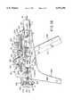
- FIG. 3is longitudinal cross-section of a steerable deployment head of the present invention
- FIG. 4is a side view partially in section of a steerable deployment head of the present invention in a radially displaced stance
- FIG. 5is a cross-section taken along line 5--5 of FIG. 3;
- FIG. 6is a cross-section taken along line 6--6 of FIG. 3;
- FIG. 7is a cross-section taken along line 7--7 of FIG. 3;
- FIG. 8is a cross-section taken along line 8--8 of FIG. 3;
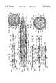
- FIG. 9is a front view of a steerable deployment head of the present invention within a body lumen which has been suitably radially displaced so as to intraluminally distend and anchor a prosthesis;
- FIG. 10is a cross-section taken along line 10--10 of FIG. 4;
- FIG. 11is a top view of an actuator subassembly and a catheter mounting subassembly in assembled relationship to one another for remotely controlling the deployment head of the present invention
- FIG. 12is a front view of the assembly of FIG. 11;
- FIG. 13is a partial cross-section of one side of the assembly taken substantially along line 13--13 of FIG. 11;
- FIG. 14is a cross-section taken along line 14--14 of FIG. 13 showing the catheter mounting subassembly in spaced proximity to the actuator subassembly;
- FIG. 15is a cross-section taken along line 15--15 of FIG. 13 showing the catheter mounting subassembly and the actuator subassembly in abutting relationship to one another;
- FIG. 16is a partial cross-section of a second side of the actuator subassembly and the catheter mounting subassembly taken substantially along line 16--16 of FIG. 11
- FIG. 17is the same view as FIG. 13 showing the operation of a trigger and an actuating lever
- FIG. 18is a cross-section taken along the line 18--18 of FIG. 13 showing the catheter mounting subassembly and the actuator subassembly in engaging relationship to one another;
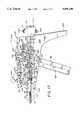
- FIG. 19is side view partially in section of a modified embodiment showing a deployment head of the present invention and its coupling to two articulated members.
- Graftstent complex 44comprises a thin-walled, crimped, knitted graft 46 of DACRON, expandable PTFE, or similar material which overlaps and is sutured to a pair of stents 48a and 48b.
- Suitable vascular graftsthat may be used include Model 80S07TW by Impra, of Tempe, Ariz.; and Model VT06070L by Gortex, of Flagstaff, Ariz.
- One stent usable with the present inventionis the RM1001 stent manufactured by Stentco, Inc. of Elmwood Park, N.J.
- Distal stent 48ais mounted on a head 50 which has a support surface comprised of four radially displaceable wings 52a, 52b, 52c, and 52d (see FIGS. 5 and 9). All of the wings may be the same.
- the stentsmay have an unexpanded diameter of five to ten millimeters or less for delivery purposes.
- the stent on head 50is radially distended to an expanded diameter by a mechanical linkage actuated by a control mechanism 54, described below.
- the radial expansion of the stentis continued until it invaginates into an arterial wall and fastens itself by a friction seal, as also described below.
- stents 48a and 48bare advanced to a designated site within a patient's vascular system under fluoroscopic control in conventional manner by sliding the device relative to a separately inserted guide wire 56.
- Head 50includes an annular support 58 (FIGS. 2 and 3) that is mounted at a proximal face by a pin 60 to a first ferrule 62.
- Ferrule 62is press fit onto the distal end of an elongate flexible shaft 64.
- Pin 60enables head 50 to pivot with respect to shaft 64.
- Shaft 64comprises a wire wound coil 66 (FIG. 10) surrounding a multilumen plastic catheter 68.
- Catheter 68includes a central lumen 70 that receives the proximal end of the guide wire such as when head. 50 is advanced to the designated site within a patient.
- the proximal end of shaft 64is retained with a nose cone 114.
- the catheterincludes various lumens (not numbered) for receiving the control wires as described below.
- the guide wireis used in conventional fashion to guide the graftstent complex 44 through the patient's vascular system.
- Guide wire 56is preferably at least 0.025 inches in diameter, and may be 0.035 inches or more.
- the guide wiremay be of tempered stainless steel and is conventionally covered with a synthetic material, such as TEFLON.
- a taut steering wire 72is shown looped at its distal end through suitable holes in the arms 84 and bifurcated lugs 106 at the distal end of annular support 58 on transverse sides of pin 60.
- head 50may be manually manipulated within the patient's vascular system to facilitate advancement of the device and the deployment of the stent in an angulated arterial segment.
- the steerability of head 50 about pin 60aids the surgeon in negotiating the tortious or twisty arteries in the patient's vascular system.
- head 50is free to pivot 30° about first ferrule 62.
- Steering wire 72is housed in an additional lumen within multilumen catheter 68 along with initiator and deployment wires 78,80 which are used for operating head 50, as shown in FIG. 10.
- steering wire 72is 0.010 inches in diameter or less.
- the apparatus of the present inventiondeploys the stent by radially displacing the wings through a mechanical coupling which consists of four pairs of arms 82,84, each pair associated with each wing, together with a tubular slide 86 and an initiator 88, both of which are axially slideably mounted with respect to the guide wire and are commonly associated with each of the wings.
- the distal ends of two of the arms 82are pivotally attached to the distal end of slide 86 by deployment wire 80 (FIG. 5) which extends from the control mechanism 54 through shaft 64 and is looped at its distal end through suitable holes in the arms 82 and bifurcated lugs 94 at the distal end of slide 86.
- the distal ends of the other two arms 82are pivotally attached to the distal end of slide 86 by pins 96.
- the proximal ends of arms 82are pivotally attached to the distal ends of arms 84 and an intermediate part of a corresponding wing 52a,b,c,d by pins 118 (see FIGS. 4 and 6).
- the proximal ends of arms 84are pivotally mounted to annular support 58 by pins 120 (FIG. 8) or steering wire 72 (FIG. 19), as described above.
- tension applied to the looped deployment wire 80will cause the arms to buckle (FIG. 4) which in turn deploys the wings 52a,b,c,d outwardly.
- Deployment wire 80is anchored at its proximal ends, preferably, to a multiply ribbed anchor 90 (FIG. 13) which mates with control mechanism 54 such that a calibrated force may be directly transmitted from control mechanism 54 to the tubular slide by squeezing a trigger 92 to effect a radial displacement of the wings, all while intraluminal fluid flow is minimally impeded within the patient's vascular system.
- Deployment wire 80is capable of transmitting compressive forces, and preferably has a diameter of 0.014 inches or less. Thus, when trigger 92 is released, the deployment wire moves axially toward the distal end of head 50 thereby towing the tubular slide to its rest position and radially recoiling the wings.
- the direct transmission of a physical force from trigger 92 to head 50causes the device of the present invention to operate substantially instantaneously without the delays associated with the filling of a balloon.
- the uniform radial separation of the wings under the direction of the mechanical linkage of tubular slide 86 and coupling arms 82,84avoids the risk of stent or graftstent rotation, a common problem with wrapped angioplasty balloon deployment designs.
- a slot 98 (FIG. 4) in each wing 52accommodates bifurcated lugs 94 and coupling ann 82 when the wings are recoiled. This allows for a more compact profile of head 50 for intraluminal delivery and removal after the surgical procedure is complete (see FIG. 2).
- Head 50can be formed with a profile of approximately five millimeters which permits the introduction of stent 48 into smaller vascular systems than a conventional balloon-stent deployment design may facilitate.
- Head 50includes cylindrical initiator 88 for initiating the radial motion of the wings from their recoiled stance shown in FIG. 3. This makes it easier to fully deploy the wings 52a, b, c, d by applying tension to deployment wire 80.
- An initiator wire 78which extends through the central lumen of initiator 88 is anchored to the initiator in a circumferential slot 100, and is used to axially slide the initiator with respect to the arms 84.
- Slot 100is preferably formed with a pair of opposing holes 102 through which initiator wire 78 may be threaded and wrapped securely (see FIG. 7). A force applied to the proximal end of initiator wire 78 by control mechanism 54 slides initiator 88 with respect to guide wire 56.
- Advancement of initiator 88 toward the distal face of annular support 58causes it to engage sloped surfaces 104 (shown by the dashed lines of FIG. 3) of the coupling arms 84.
- the sloped surfaces 104have a 15° pitch.
- each coupling arm 84buckles slightly about a pair of lugs 106, i.e. the distal portions of the coupling arms pivot slightly away from tubular slide 86 to initiate movement of each respectively coupled wing slightly radially outward.
- Coupling arms 82similarly pivot about lugs 94 while tubular slide 86 is moved slightly toward the distal face of annular support 58.
- the portion of initiator 88 that bears against surface 104is shaped as a frustrum so that frictional forces are minimized. Reduced frictional forces permit use of a thinner, more compact initiator wire 78.
- initiator wireis 0.014 inches or less in diameter.
- wings 52can be fully radially displaced, as shown in FIG. 4, by advancing tubular slide 86 toward the distal face of annular support 58 by squeezing trigger 92 to apply tension to deployment wire 80.
- head 50is shown within a body lumen 108 with tubular slide 86 retracted toward the distal face of annular support 58, as by trigger 92, to bow coupling arms 82,84 outward and radially separate the wings.
- the stent support surfaceseparates with the radial motion of the wings, the stent deforms at four contact points 110a, 110b, 110c, and 110d.
- the stentis anchored to the walls of the body lumen when the wings have dilated substantially to the diameter of the body lumen.
- body lumen 108were the abdominal aortic artery, the wings would be dilated to approximately 35 to 40 mm.
- the wingsare preferably recoiled and rotated so that the stent can be redistended at four other contact points.
- head 50has been rotated approximately 45° and redistended to contact the body lumen at points 112a, 112b, 112c, and 112d, as shown by the dashed lines. Rotation and redistention may be repeated as many times as necessary to firmly seat the stent in the body lumen.
- Each of the wingspreferably has a stepped inner surface 116 m accommodate coupling arms 82,84 (see FIG. 7).
- Each wingalso has a primary rib 122 at a distal end and a secondary rib 124 at a proximal end.
- a recess 126 between the wingsholds the stent in place.
- head 50 and shaft 64form a delivery system that can be preconfigured with a particular stent 48 or graftstent complex 44 of suitable length for a particular surgical procedure.
- the extent of expansion of the stentis directly controlled by the travel of trigger 92 which governs tubular slide 86. This travel can be calibrated to a predetermined level of expansion, e.g., thirty-five min.
- the stentcan be immediately redilatated to a larger size without the introduction of a new deployment head 50 or a catheter exchange.
- the stentcan be incrementally dilated to larger sizes on a moment-by-moment basis depending on real time fluoroscopic images and the surgeon's discretion as a function of the actual arterial dimensions instead of relying on estimated dimensions that are conventionally made prior to the procedure using an angiogram. This affords a decrease in blood loss during such redilation procedures and cuts down on the amount of time and cost involved with conventional procedures which could require multiple angioplasty catheter exchanges to redilate the stent.
- the apparatus of the present inventionmay be used without stent 48 for native artery angioplasty.
- head 50would be advanced to the designated site within a patient's vascular system under fluoroscopic control in conventional manner by sliding the device over a separately inserted guide wire 56, as described above.
- head 50is advanced to the site of a stenosis at which time trigger 92 is squeezed to effect a radial displacement of wings 54a, b, c, d against the stenosis all while intraluminal fluid flow is minimally impeded within the patient's vascular system.
- any plaque or other deposit on the walls of a body lumenwill be flattened by the radially displaced wings themselves.
- control mechanism 54as may be used with head 50 and shaft 64. Several views are given so that the geometry of control mechanism 54 can be better appreciated.
- the control mechanismcomprises a catheter mounting subassembly 200 and an actuator subassembly 202 (FIGS. 11 and 13).
- the catheter mounting subassemblycomprises a plate 204 which supports the rotatable nose cone 114, a multiply ribbed anchor 90 attached to the proximal end of the deployment wire 80, an anchor 242 attached to the proximal end of the initiator wire 78, and steering lever 74 attached to the proximal end of the steering wire 72. (FIG. 16).
- the catheter mounting subassemblymates with a first side 206 of actuator subassembly 202 to form an assembled control mechanism 54.
- a C-shaped retaining ring 208is attached to the proximal end of plate 204 by a pair of screws 210 to unite mounting subassembly 200 with nose cone 114.
- the nose conehas a circumferential groove 212 (see FIG. 13) that permits it to be rotatably supported in retaining ring 208 to plate 204. It is desirable to have the nose cone rotatably supported in the catheter mounting subassembly so that head 50 can be rotated once located within a patient's body for redistending the stent at contact points other than where the stent is first distended.
- the nose coneis provided with a stop 214, as shown in FIG. 12, that limits rotation to approximately 360°.
- a click stopmay be provided at regular intervals, for example, 45°, to provide a tactile indication of the amount of rotation brought about by rotation of nose cone 114.
- Multiply ribbed anchor 90has at its distal end a cylindrical sleeve 91 that is slideably mounded in an annular recess 115 in the proximal face of nose cone 114.
- Attached by additional screws 211 to the distal end of plate 204is an end plate 216 which supports steering lever 74 which is connected to the proximal ends of steering wire 72 (see FIG. 16).
- the steering leveris pivotally secured onto a pivot pin 220 with a locking washer 222 that is press fit onto pivot pin 220.
- Steering wire 72is directed through a hole 226 in the steering lever to a clamping screw 228.
- the natural angle that head 50 assumescan be set by tightening a set screw 230.
- head 50can be manually manipulated for advancement to the desired portion of the vascular system by rotating steering lever 74 with set screw 230 loosened.
- FIGS. 14 and 15show cross-sections of the mounting subassembly and actuator subassembly before and after control mechanism 54 is assembled, respectively. Assembly is facilitated by a peg 234 and a slot 232 complementarily formed on each of the mounting subassembly and actuator subassembly, as shown in FIG. 14, to guide the catheter mounting subassembly and actuator subassembly together.
- Shaft 64is received in control mechanism 54 by means of catheter mounting subassembly 200 after the stent or graftstent complex has been loaded upon shaft 64 and delivered to the desired location within a patient's vascular system.
- Mounting subassembly 200is then secured to actuator subassembly 202 to form a single mechanism as by screws 236, shown in FIG. 16, or by any other means to hold two components together.
- the mounting subassemblyenables head 50 to be operated remotely by trigger 92, yet together provides an automatic calibration of the distention of the stent, as described below.
- the travel of trigger 92is calibrated to the radial motion of the wings so that dilation of the stent is certain and precise.
- Deployment wire 80which is coupled at its distal end to tubular slide 86, is rigidly coupled at its proximal end to anchor 90 by a washer 238 and a nut 240 (see FIG. 13) so that a force applied to anchor 90 by trigger 92 is conveyed to tubular slide 86 to displace the wings and distend any stent 48 thereon.
- initiator wire 78 coupled at its distal end to initiator 88is coupled at its proximal end to a spool-shaped anchor 242 by a washer 244 and a nut 246. A force applied to anchor 242 by actuating lever 248 is thus conveyed to initiator 88 to displace the wings slightly radially outward, as described above in connection with FIG. 3.
- trigger 92is shown coupled to anchor 90 by a slotted yoke slide 250 terminated at the distal end in a yoke 252.
- Yoke 252selectively engages multiply ribbed anchor 90 between any one of several ribs when the catheter mounting subassembly is assembled with the actuator subassembly (see FIG. 18). This is a self-zeroing control to account for cable bending, as more completely described in connection with the operation of the device.
- the actual set of ribs on anchor 90 to which yoke 252 engagesis determined based on the orientation of shaft 64 in the patient's body.
- a link pin 254 attached to the triggerengages one of a plurality of vertical slots 256 in yoke slide 250 so that the travel of the trigger remains accurately calibrated to the force conveyed to anchor 90 which, in turn, governs the radial displacement or recoil of the wings.
- the triggerpivots on a pin 258 in an arcuate shaped milled recess 260 formed in second side 224 of actuator subassembly 202. As the trigger pivots on pin 258, link pin 254 travels in an arc along with the trigger.
- Link pin 254draws yoke slide 250 linearly forwards and backwards in actuator subassembly 202 by engagement with vertical slots 256.
- Vertical slots 256accommodate the arc traced by link pin 254 as it travels with the trigger while translating the pivotal motion of the trigger into the linear motion of yoke slide 250. This pivotal motion is in response to a force applied to a grasp handle 262 which may be provided to ensure a firm control over the trigger.
- Rack 280terminated at one end with a yoke 282.
- Rack 280has an aperture 284 so that it can slide in actuator subassembly 202 without contacting pin 254 of trigger 92.
- Rack 280has on a top margin thereof a set of teeth 286 that cooperate with a pinion gear 288 formed on one end of actuating lever 248.
- Actuating lever 248pivots about a pin 290 between a pair of lever stops 292a,b (see FIG. 11). From FIGS. 16 and 17, it is seen that as the actuating lever 248 pivots from 292a to 292b, pinion gear 288 drives rack 280 in an opposite direction and tows anchor 242 therealong.
- trigger 92is normally biased by a spring 266 into a forward position, away from a butt 268 of the actuator subassembly.
- Spring 266is housed in a horizontal slot 270 and urges a disc 272 against edge 264 in resistance to any force applied to the trigger.
- trigger 92may include an aperture 274 for receiving a peg 276 from a corresponding hole in actuator subassembly 202. Peg 276 restrains the trigger from pivotal motion until removed from aperture 274.
- a set of peg holes 278 extending toward butt 268is shown for limiting the motion of the trigger to the hole in which peg 276 has been placed.
- each of holes 278is calibrated to the relative displacement of the wings so that holes 278 may be labeled, for example, 20, 24, 26, 28, 30, and so on, to provide a millimeter scale of the distention of the stent upon squeezing the trigger to a particular one of holes 278.
- Control mechanism 54includes a trigger lock mechanism that restrains the trigger from pivotal motion unless a button 300 on a top surface 302 of the control mechanism is first depressed. This button is attached to a lever lock 304 by a pivot 306 (FIGS. 16 and 17).
- the lever lock 304pivots about a pivot pin 308 and is normally biased by a spring 3 10 into a locked position (see FIGS. 13 and 18).
- Spring 310is connected between a pin 311 below pivot pin 308 on lever lock 304 and a post 312 disposed in a pair of slots 314 formed in actuator subassembly 202.
- a pin 316(FIGS.
- trigger 92radially displaces the wings by the coupling of the trigger to the wings by way of link pin 316, slotted yoke slide 250, yoke 252, multiply ribbed anchor 90, deployment wire 80, tubular slide 86, and coupling arms 82.
- FIG. 19shows a modification of the above described embodiment.
- a second ferrule 62'is formed on the proximal end of first ferrule 62.
- a pivot pin 60'pivotally couples the second ferrule to the first ferrule on the distal end of the shaft.
- the second ferruleis rotated 90° with respect to the first ferrule to increase the steerability of head 50.
- a second taut steering wire 72'is looped at its distal end through suitable holes formed transverse to pin 60' at the proximal end of first ferrule 62.
- head 50is universally steerable by manipulating steering wires 72,72'.
- Multilumen catheter 68has at least one lumen for a wire coupled to the second ferrule of this modified embodiment.
- second ferrule 62'is press fit onto the distal end of elongate flexible shaft 64.
- a surgeonPrior to performing an operation using the device of the present invention, a surgeon first determines the nature of the atherosclerosis, that is whether there is a stenosis or aneurysm. This may conventionally be determined by means of an angiogram.
- native artery angioplastycan be performed by using the device, in the manner described below, without a stent 48a or a stent 48a may be used to support the walls of body lumen 108 from constricting.
- a graftstent complex 44 of suitable lengthis required to bypass an aneurysm.
- the angiogramfurther provides the surgeon with an indication of the lumen width in the region surrounding the stenosis or aneurysm.
- This indication of lumen widthis advantageously used to set the maximum travel of trigger 92 by setting peg 276 in an appropriate one of calibrated holes 278.
- a suitable stent or stentgraft complexmay be selected.
- the entire graftstent 44can be prefabricated and mounted on head 50 in a manner ready for connection to actuator subassembly 202 and subsequent deployment; a surgeon need only specify the length of graft 46 necessary to bypass an aneurysm and the maximum distention desired of stent 48a. The length of the aneurysm is determined during the angiogram.
- a guide wire 56is advanced within a conventional guide catheter or sheath through a patient's vascular system to a position beyond the stenosis or aneurysm.
- Head 50 at the distal end of the elongate flexible shaft 64is then advanced over the proximal end of guide wire until it reaches the site of the stenosis or aneurysm.
- a fluoroscopic image of the patient's abdominal cavitymay assist locating head 50 relative to the designated site. Where head 50 is formed of plastic or epoxy materials, it is advantageously provided with a radiopaque portion to assist in the fluoroscopic alignment process.
- At the distal end of shaft 64is an unmounted catheter mounting subassembly 200.
- a stent or stentgraft complexis to be used, it is loaded upon head 50 at the distal end of shaft 64 prior to being inserted into the patient.
- a sheath 330is placed over the prosthesis for smooth delivery to the site of a narrowing or an aneurysm.
- steering lever 74may be manipulated by the surgeon so that catheter 64 successfully negotiates the tortious and twisty arteries encountered.
- the steering levercan be set by screw 230 so that head 50 will retain its naturally assumed angle during the displacement of wings 54a, b, c, and d.
- shaft 64will likely have bends in it between its distal and proximal ends. These bends will pull on the initiator and deployment wires 78, 80 which in turn will axially reposition anchors 90, 242 with respect to nose cone 114 at the proximal end of shaft 64.
- the catheter mounting subassembly and the actuator subassemblyare joined to form an assembled control mechanism 54.
- the sheathwhen present, is withdrawn by a sheath retractor (not shown) for displacement of the wings.
- the actuating lever 248is then advanced from lever stop 292a to 292b to draw initiator 88 toward annular support 58 and to separate the wings slightly radially.
- the trigger lock button 300can then be released and the trigger 92 compressed toward butt 268 to draw tubular slide 86 toward annular support 58 and displace the wings.
- the trigger 92may be squeezed until it hits peg 276 (FIG. 17) at which point stent 48a may be expanded sufficiently to anchor it to body lumen 108, at least according to the angiogram data collected prior to the operation.
- Stent 48acan be incrementally dilated to larger sizes by removing peg 276 and squeezing trigger 92 beyond the hole 278 which peg 276 formerly occupied. This may be done on a moment-by-moment basis depending on real time fluoroscopic images and the surgeon's discretion as a function of the actual arterial dimensions.
- spring 266urges the trigger to its rest position which conveys a pushing force through yoke 252 and deployment wires 80 to tubular slide 86.
- tubular slide 86is pushed away from annular support 58, the wings return to a radially recoiled stance and stent 48a retains its radially expanded circumstance.
- the direct transmission of a physical force from trigger 92 to head 50permits rapid displacement and recoil of the wings. Displacement and recoil can be performed in virtually less than a second, as compared to the time required for balloon dilatation which may be as much as twenty to thirty seconds and sometimes up to a minute. Relative to balloon based devices, therefore, the present invention operates substantially instantaneously without the delays associated with filling a balloon. All the while, intraluminal fluids flow between the radially displaced wings. Additionally, because the wings uniformly separate radially under the direction of the mechanical linkage of tubular slide 86 and coupling arms 82,84, there is no risk of stem or graftstent rotation, a common problem with wrapped angioplasty balloon deployment designs.
- Head 50can then be rotated so that stent 48a can be redilated at contact points other than where it has already been dilated. This procedure better secures the stent to the body lumen. Rotation is effected by rotating nose cone 114. This turns shaft 64 and head 50 and thereby angularly repositions wings 54 with respect to the body lumen 108. Trigger 92 can then be squeezed to distend stent 48a at a new set of contact points. This procedure may be repeated as many times as desired until stent 48a is firmly seated. Alternatively, rotation of head 50 and relocation of wings 54 aid in the procedure of native artery angioplasty in the absence of a stent by flattening plaque and any other deposit on the body lumen.
- a stent 48bmust be deployed once stent 48a has been deployed.
- Shaft 64is withdrawn, preferably with the assistance of a fluoroscopic image of the patient's abdominal cavity, until head 50 is surrounded by undistended stent 48b.
- stent 48bwill pass over secondary rib 124 and become seated on the support surface when one margin of stent 48b abuts primary rib 122.
- head 50is formed of plastic or epoxy materials, it is advantageously provided with a radiopaque portion to assist in the fluoroscopic alignment process.
- actuating lever 248, button 300, and trigger 92are used to deploy stent 48b.
- shaft 64 and guide wire 56can be withdrawn from the patient's vascular system.
- multiple stents 48a and 48bmay be deployed with a single introduction into a patient's vascular system.
- Head 50may be produced in a disposable or non-disposable fashion. Where head 50 is to be disposed of after usage, at least wings 52, tubular slide 86, coupling arms 82,84, initiator 88, and annular support 58 may be compression molded or extruded from an epoxy material or plastic.
- the same components of head 50 listed aboveare advantageously formed of stainless steel where head 50 is intended to be reused in a subsequent procedure.
- One skilled in the artwould recognize that the choice of materials for the head affects the radiopacity of the head. Thus, an epoxy or plastic head would be radiolucid as compared to a stainless steel head which would be radiopaque.
- Sheath 330may be of a plastic or teflon material.
- the materials most commonly used as prosthetic arteriesare PTFE ("GORTEX”) and DACRON, however, other suitable grafts may be used with this device. No single prosthetic material has surfaced as being superior to others. Excellent results may be also had using a patient's own accessory vein, albeit with more imposition to the patient.
- the inventionis intended for use in deploying stents and attachment devices, i.e. devices which may be attached to a body lumen such as an artery, for example to secure a graft in place.
- stentis intended to also include such attachment devices.
- the inventioncan be used with any radially expandable stent, including stents which are partially self-expanding.
Landscapes
- Health & Medical Sciences (AREA)
- Biomedical Technology (AREA)
- Engineering & Computer Science (AREA)
- Animal Behavior & Ethology (AREA)
- Public Health (AREA)
- Heart & Thoracic Surgery (AREA)
- Veterinary Medicine (AREA)
- Life Sciences & Earth Sciences (AREA)
- Vascular Medicine (AREA)
- General Health & Medical Sciences (AREA)
- Cardiology (AREA)
- Oral & Maxillofacial Surgery (AREA)
- Transplantation (AREA)
- Anesthesiology (AREA)
- Hematology (AREA)
- Media Introduction/Drainage Providing Device (AREA)
- Prostheses (AREA)
- Materials For Medical Uses (AREA)
Abstract
Description
Claims (13)
Priority Applications (6)
| Application Number | Priority Date | Filing Date | Title |
|---|---|---|---|
| US08/376,352US5591196A (en) | 1994-02-10 | 1995-01-23 | Method for deployment of radially expandable stents |
| AU19182/95AAU1918295A (en) | 1994-02-10 | 1995-02-08 | Apparatus and method for deployment of radially expandable stents by a mechanical linkage |
| PCT/US1995/001830WO1995021593A1 (en) | 1994-02-10 | 1995-02-08 | Apparatus and method for deployment of radially expandable stents by a mechanical linkage |
| JP52139995AJP3601828B2 (en) | 1994-02-10 | 1995-02-08 | Device for deploying a radially expandable stent by mechanical linkage |
| EP95911714AEP0744930A1 (en) | 1994-02-10 | 1995-02-08 | Apparatus and method for deployment of radially expandable stents by a mechanical linkage |
| CA002182721ACA2182721A1 (en) | 1994-02-10 | 1995-02-08 | Apparatus and method for deployment of radially expandable stents by a mechanical linkage |
Applications Claiming Priority (2)
| Application Number | Priority Date | Filing Date | Title |
|---|---|---|---|
| US08/196,278US5443477A (en) | 1994-02-10 | 1994-02-10 | Apparatus and method for deployment of radially expandable stents by a mechanical linkage |
| US08/376,352US5591196A (en) | 1994-02-10 | 1995-01-23 | Method for deployment of radially expandable stents |
Related Parent Applications (1)
| Application Number | Title | Priority Date | Filing Date |
|---|---|---|---|
| US08/196,278ContinuationUS5443477A (en) | 1994-02-10 | 1994-02-10 | Apparatus and method for deployment of radially expandable stents by a mechanical linkage |
Publications (1)
| Publication Number | Publication Date |
|---|---|
| US5591196Atrue US5591196A (en) | 1997-01-07 |
Family
ID=26891785
Family Applications (1)
| Application Number | Title | Priority Date | Filing Date |
|---|---|---|---|
| US08/376,352Expired - LifetimeUS5591196A (en) | 1994-02-10 | 1995-01-23 | Method for deployment of radially expandable stents |
Country Status (6)
| Country | Link |
|---|---|
| US (1) | US5591196A (en) |
| EP (1) | EP0744930A1 (en) |
| JP (1) | JP3601828B2 (en) |
| AU (1) | AU1918295A (en) |
| CA (1) | CA2182721A1 (en) |
| WO (1) | WO1995021593A1 (en) |
Cited By (120)
| Publication number | Priority date | Publication date | Assignee | Title |
|---|---|---|---|---|
| US5776181A (en)* | 1995-07-25 | 1998-07-07 | Medstent Inc. | Expandable stent |
| US6129756A (en)* | 1998-03-16 | 2000-10-10 | Teramed, Inc. | Biluminal endovascular graft system |
| US6156062A (en)* | 1997-12-03 | 2000-12-05 | Ave Connaught | Helically wrapped interlocking stent |
| US6224609B1 (en) | 1998-03-16 | 2001-05-01 | Teramed Inc. | Bifurcated prosthetic graft |
| US6261318B1 (en) | 1995-07-25 | 2001-07-17 | Medstent Inc. | Expandable stent |
| US6273909B1 (en) | 1998-10-05 | 2001-08-14 | Teramed Inc. | Endovascular graft system |
| WO2001062145A1 (en)* | 2000-02-22 | 2001-08-30 | Power Medical Interventions, Inc. | A vessel and lumen expander attachment for use with an electromechanical driver device |
| US20020016597A1 (en)* | 2000-08-02 | 2002-02-07 | Dwyer Clifford J. | Delivery apparatus for a self-expanding stent |
| US20020022860A1 (en)* | 2000-08-18 | 2002-02-21 | Borillo Thomas E. | Expandable implant devices for filtering blood flow from atrial appendages |
| US20020058986A1 (en)* | 2000-11-16 | 2002-05-16 | Landau George D. | Stent graft with branch leg |
| US6478813B1 (en) | 1997-08-01 | 2002-11-12 | Peter T. Keith | Method for joining grafts in a common body passageway |
| US6482227B1 (en) | 1998-03-30 | 2002-11-19 | Cordis Corporation | Stent graft having improved attachment within a body vessel |
| US20020183823A1 (en)* | 2001-06-04 | 2002-12-05 | Ramesh Pappu | Cardiac stimulating apparatus having a blood clot filter and atrial pacer |
| US20020198554A1 (en)* | 2001-03-14 | 2002-12-26 | Whitman Michael P. | Trocar device |
| US20030023262A1 (en)* | 2001-07-18 | 2003-01-30 | Jeffrey Welch | Cardiac implant device tether system and method |
| US20030057156A1 (en)* | 2001-03-08 | 2003-03-27 | Dean Peterson | Atrial filter implants |
| US6551303B1 (en) | 1999-10-27 | 2003-04-22 | Atritech, Inc. | Barrier device for ostium of left atrial appendage |
| US20030105478A1 (en)* | 2001-11-30 | 2003-06-05 | Whitman Michael P. | Surgical device |
| US6575994B1 (en) | 1994-02-10 | 2003-06-10 | Teramed, Inc. | Method and apparatus concerning bypass grafts |
| US20030130677A1 (en)* | 2002-01-08 | 2003-07-10 | Whitman Michael P. | Surgical device |
| US20030130724A1 (en)* | 2002-01-08 | 2003-07-10 | Depalma Donald F. | Supra-renal anchoring prosthesis |
| US6626938B1 (en) | 2000-11-16 | 2003-09-30 | Cordis Corporation | Stent graft having a pleated graft member |
| US6652556B1 (en) | 1999-10-27 | 2003-11-25 | Atritech, Inc. | Filter apparatus for ostium of left atrial appendage |
| US6652555B1 (en) | 1999-10-27 | 2003-11-25 | Atritech, Inc. | Barrier device for covering the ostium of left atrial appendage |
| US20030225425A1 (en)* | 2002-06-03 | 2003-12-04 | David Kupiecki | Devices and methods for interconnecting vessels |
| US20040097959A1 (en)* | 2001-01-18 | 2004-05-20 | Ev3 Peripheral, Inc | Stent delivery system with spacer member |
| US6743219B1 (en) | 2000-08-02 | 2004-06-01 | Cordis Corporation | Delivery apparatus for a self-expanding stent |
| US20040186511A1 (en)* | 2003-03-20 | 2004-09-23 | Adam Stephens | Control handle for intraluminal devices |
| US20040193179A1 (en)* | 2003-03-26 | 2004-09-30 | Cardiomind, Inc. | Balloon catheter lumen based stent delivery systems |
| US20040188304A1 (en)* | 2002-12-31 | 2004-09-30 | Bonnette Michael J. | Packaging system with oxygen sensor |
| US20040230222A1 (en)* | 1999-11-08 | 2004-11-18 | Van Der Burg Erik J. | System for left atrial appendage occlusion |
| US20050004652A1 (en)* | 1998-11-06 | 2005-01-06 | Van Der Burg Eric J. | Method for left atrial appendage occlusion |
| US6843802B1 (en) | 2000-11-16 | 2005-01-18 | Cordis Corporation | Delivery apparatus for a self expanding retractable stent |
| US6887268B2 (en) | 1998-03-30 | 2005-05-03 | Cordis Corporation | Extension prosthesis for an arterial repair |
| US20050187576A1 (en)* | 2004-02-23 | 2005-08-25 | Whitman Michael P. | Surgical cutting and stapling device |
| US6942692B2 (en) | 2000-11-16 | 2005-09-13 | Cordis Corporation | Supra-renal prosthesis and renal artery bypass |
| US20050209675A1 (en)* | 2004-03-02 | 2005-09-22 | Ton Dai T | Corewire actuated delivery system with fixed distal stent-carrying extension |
| US20060111771A1 (en)* | 2003-03-26 | 2006-05-25 | Ton Dai T | Twist-down implant delivery technologies |
| US20060206148A1 (en)* | 1999-11-08 | 2006-09-14 | Khairkhahan Alexander K | Method of implanting an adjustable occlusion device |
| US20060264952A1 (en)* | 2005-05-18 | 2006-11-23 | Nelson Charles L | Methods of Using Minimally Invasive Actuable Bone Fixation Devices |
| US20060287643A1 (en)* | 2005-06-16 | 2006-12-21 | Marsh Surgical, Inc. | Surgical instrument with detachable sleeve assembly |
| US7169164B2 (en) | 2000-09-21 | 2007-01-30 | Atritech, Inc. | Apparatus for implanting devices in atrial appendages |
| US7169170B2 (en) | 2002-02-22 | 2007-01-30 | Cordis Corporation | Self-expanding stent delivery system |
| US20070027522A1 (en)* | 2005-06-14 | 2007-02-01 | Chang Jean C | Stent delivery and guidewire systems |
| US20070066993A1 (en)* | 2005-09-16 | 2007-03-22 | Kreidler Marc S | Intracardiac cage and method of delivering same |
| US20070073379A1 (en)* | 2005-09-29 | 2007-03-29 | Chang Jean C | Stent delivery system |
| US20070100418A1 (en)* | 2005-11-02 | 2007-05-03 | David Licata | Pass-through restraint electrolytic implant delivery systems |
| US7229472B2 (en) | 2000-11-16 | 2007-06-12 | Cordis Corporation | Thoracic aneurysm repair prosthesis and system |
| US7267685B2 (en) | 2000-11-16 | 2007-09-11 | Cordis Corporation | Bilateral extension prosthesis and method of delivery |
| WO2007070792A3 (en)* | 2005-12-13 | 2007-12-13 | Cordis Dev Corp | Actuator handle for use with medical device deployment systems |
| US20080115789A1 (en)* | 2004-04-07 | 2008-05-22 | Green Philip A | Variable size endotracheal tube |
| US20080132896A1 (en)* | 2006-11-22 | 2008-06-05 | Sonoma Orthopedic Products, Inc. | Curved orthopedic tool |
| US20080140078A1 (en)* | 2006-11-22 | 2008-06-12 | Sonoma Orthopedic Products, Inc. | Surgical tools for use in deploying bone repair devices |
| US20080149115A1 (en)* | 2006-11-22 | 2008-06-26 | Sonoma Orthopedic Products, Inc. | Surgical station for orthopedic reconstruction surgery |
| US20080161805A1 (en)* | 2006-11-22 | 2008-07-03 | Sonoma Orthopedic Products, Inc. | Fracture fixation device, tools and methods |
| US20080221666A1 (en)* | 2006-12-15 | 2008-09-11 | Cardiomind, Inc. | Stent systems |
| US20080243223A1 (en)* | 2007-03-29 | 2008-10-02 | Es Vascular, Ltd. | Device for affixing of tubular medical accessory to a body passage |
| US7549983B2 (en) | 1999-09-20 | 2009-06-23 | Atritech, Inc. | Method of closing an opening in a wall of the heart |
| US20090240262A1 (en)* | 2008-03-20 | 2009-09-24 | Es Vascular, Ltd. | Device for affixing prosthesis to a vessel |
| US20090270885A1 (en)* | 2005-09-29 | 2009-10-29 | Terumo Kabushiki Kaisha | Tissue closing device |
| US20090281611A1 (en)* | 2004-03-02 | 2009-11-12 | Cardiomind, Inc. | Sliding restraint stent delivery systems |
| US20100094347A1 (en)* | 2005-05-18 | 2010-04-15 | Nelson Charles L | Fracture fixation device, tools and methods |
| US7743960B2 (en) | 2002-06-14 | 2010-06-29 | Power Medical Interventions, Llc | Surgical device |
| US7785361B2 (en) | 2003-03-26 | 2010-08-31 | Julian Nikolchev | Implant delivery technologies |
| US20100331948A1 (en)* | 2009-06-26 | 2010-12-30 | Cardiomind, Inc. | Implant delivery apparatus and methods with electrolytic release |
| US20110093060A1 (en)* | 2009-07-02 | 2011-04-21 | Cartledge Richard G | Surgical Implant Devices and Methods for their Manufacture and Use |
| US7935141B2 (en) | 2005-08-17 | 2011-05-03 | C. R. Bard, Inc. | Variable speed stent delivery system |
| US20110153030A1 (en)* | 2001-08-27 | 2011-06-23 | Synecor, Llc | Positioning tools and methods for implanting medical devices |
| US8062344B2 (en) | 2001-04-30 | 2011-11-22 | Angiomed Gmbh & Co. Medizintechnik Kg | Variable speed self-expanding stent delivery system and luer locking connector |
| US8500789B2 (en) | 2007-07-11 | 2013-08-06 | C. R. Bard, Inc. | Device for catheter sheath retraction |
| US8808346B2 (en) | 2006-01-13 | 2014-08-19 | C. R. Bard, Inc. | Stent delivery system |
| US8961516B2 (en) | 2005-05-18 | 2015-02-24 | Sonoma Orthopedic Products, Inc. | Straight intramedullary fracture fixation devices and methods |
| US9060820B2 (en) | 2005-05-18 | 2015-06-23 | Sonoma Orthopedic Products, Inc. | Segmented intramedullary fracture fixation devices and methods |
| US9078779B2 (en) | 2006-08-07 | 2015-07-14 | C. R. Bard, Inc. | Hand-held actuator device |
| US9113878B2 (en) | 2002-01-08 | 2015-08-25 | Covidien Lp | Pinion clip for right angle linear cutter |
| US9138335B2 (en) | 2006-07-31 | 2015-09-22 | Syntheon Cardiology, Llc | Surgical implant devices and methods for their manufacture and use |
| US9155574B2 (en) | 2006-05-17 | 2015-10-13 | Sonoma Orthopedic Products, Inc. | Bone fixation device, tools and methods |
| US9186177B2 (en) | 2001-03-14 | 2015-11-17 | Covidien Lp | Trocar device |
| US9326872B2 (en) | 2010-08-17 | 2016-05-03 | W. L. Gore & Associates, Inc. | Forced deployment sequence handle assembly with independent actuating mechanism |
| WO2016141295A1 (en)* | 2015-03-05 | 2016-09-09 | Merit Medical Systems, Inc. | Vascular prosthesis deployment device and method of use |
| US9474516B2 (en) | 2011-11-08 | 2016-10-25 | Boston Scientific Scimed, Inc. | Handle assembly for a left atrial appendage occlusion device |
| US9566178B2 (en) | 2010-06-24 | 2017-02-14 | Edwards Lifesciences Cardiaq Llc | Actively controllable stent, stent graft, heart valve and method of controlling same |
| US9585743B2 (en) | 2006-07-31 | 2017-03-07 | Edwards Lifesciences Cardiaq Llc | Surgical implant devices and methods for their manufacture and use |
| US9730701B2 (en) | 2014-01-16 | 2017-08-15 | Boston Scientific Scimed, Inc. | Retrieval wire centering device |
| US9770278B2 (en) | 2014-01-17 | 2017-09-26 | Arthrex, Inc. | Dual tip guide wire |
| US9801745B2 (en) | 2010-10-21 | 2017-10-31 | C.R. Bard, Inc. | System to deliver a bodily implant |
| US9810520B2 (en) | 2015-10-05 | 2017-11-07 | General Electric Company | Measuring relative concentricity deviations in a confined space between two circumferential elements |
| US9814499B2 (en) | 2014-09-30 | 2017-11-14 | Arthrex, Inc. | Intramedullary fracture fixation devices and methods |
| US9814611B2 (en) | 2007-07-31 | 2017-11-14 | Edwards Lifesciences Cardiaq Llc | Actively controllable stent, stent graft, heart valve and method of controlling same |
| US9827093B2 (en) | 2011-10-21 | 2017-11-28 | Edwards Lifesciences Cardiaq Llc | Actively controllable stent, stent graft, heart valve and method of controlling same |
| US9883936B2 (en) | 2002-01-25 | 2018-02-06 | Boston Scientific Scimed, Inc | Atrial appendage blood filtration systems |
| USD836194S1 (en) | 2017-03-21 | 2018-12-18 | Merit Medical Systems, Inc. | Stent deployment device |
| US10667896B2 (en) | 2015-11-13 | 2020-06-02 | Cardiac Pacemakers, Inc. | Bioabsorbable left atrial appendage closure with endothelialization promoting surface |
| US10744009B2 (en) | 2017-03-15 | 2020-08-18 | Merit Medical Systems, Inc. | Transluminal stents and related methods |
| US10799378B2 (en) | 2016-09-29 | 2020-10-13 | Merit Medical Systems, Inc. | Pliant members for receiving and aiding in the deployment of vascular prostheses |
| US10952741B2 (en) | 2017-12-18 | 2021-03-23 | Boston Scientific Scimed, Inc. | Occlusive device with expandable member |
| US11026822B2 (en) | 2006-01-13 | 2021-06-08 | C. R. Bard, Inc. | Stent delivery system |
| US11123079B2 (en) | 2018-06-08 | 2021-09-21 | Boston Scientific Scimed, Inc. | Occlusive device with actuatable fixation members |
| US11241239B2 (en) | 2018-05-15 | 2022-02-08 | Boston Scientific Scimed, Inc. | Occlusive medical device with charged polymer coating |
| US11304837B2 (en) | 2015-09-15 | 2022-04-19 | Merit Medical Systems, Inc. | Implantable device delivery system |
| US11331104B2 (en) | 2018-05-02 | 2022-05-17 | Boston Scientific Scimed, Inc. | Occlusive sealing sensor system |
| US11382635B2 (en) | 2018-07-06 | 2022-07-12 | Boston Scientific Scimed, Inc. | Occlusive medical device |
| EP4032509A1 (en) | 2021-01-21 | 2022-07-27 | Inspiremd Ltd. | Handle for two-stage deployment of a stent |
| US11413048B2 (en) | 2018-01-19 | 2022-08-16 | Boston Scientific Scimed, Inc. | Occlusive medical device with delivery system |
| US11432809B2 (en) | 2017-04-27 | 2022-09-06 | Boston Scientific Scimed, Inc. | Occlusive medical device with fabric retention barb |
| US11540838B2 (en) | 2019-08-30 | 2023-01-03 | Boston Scientific Scimed, Inc. | Left atrial appendage implant with sealing disk |
| US11596533B2 (en) | 2018-08-21 | 2023-03-07 | Boston Scientific Scimed, Inc. | Projecting member with barb for cardiovascular devices |
| US11628078B2 (en) | 2017-03-15 | 2023-04-18 | Merit Medical Systems, Inc. | Transluminal delivery devices and related kits and methods |
| US11672541B2 (en) | 2018-06-08 | 2023-06-13 | Boston Scientific Scimed, Inc. | Medical device with occlusive member |
| CN116616972A (en)* | 2023-07-24 | 2023-08-22 | 深圳市飞梵实业有限公司 | Tracheal stent shifter |
| US11903589B2 (en) | 2020-03-24 | 2024-02-20 | Boston Scientific Scimed, Inc. | Medical system for treating a left atrial appendage |
| US11944314B2 (en) | 2019-07-17 | 2024-04-02 | Boston Scientific Scimed, Inc. | Left atrial appendage implant with continuous covering |
| US11963893B2 (en) | 2020-10-26 | 2024-04-23 | Merit Medical Systems, Inc. | Esophageal stents with helical thread |
| US12023036B2 (en) | 2020-12-18 | 2024-07-02 | Boston Scientific Scimed, Inc. | Occlusive medical device having sensing capabilities |
| US12090038B2 (en) | 2020-07-24 | 2024-09-17 | Merit Medical Systems , Inc. | Esophageal stents and related methods |
| US12318092B2 (en) | 2021-06-22 | 2025-06-03 | Boston Scientific Scimed, Inc. | Left atrial appendage implant |
| US12329500B2 (en) | 2020-11-30 | 2025-06-17 | Boston Scientific Scimed, Inc. | Implantable passive mean pressure sensor |
| US12349918B2 (en) | 2021-09-08 | 2025-07-08 | Boston Scientific Scimed, Inc. | Multi-sharpness split top soft tissue anchors |
| US12383278B2 (en) | 2021-07-08 | 2025-08-12 | Boston Scientific Scimed, Inc. | Left atrial appendage closure device |
| US12383201B2 (en) | 2021-02-03 | 2025-08-12 | Boston Scientific Scimed, Inc. | Medical system for treating a left atrial appendage |
Families Citing this family (7)
| Publication number | Priority date | Publication date | Assignee | Title |
|---|---|---|---|---|
| FR2743301B1 (en) | 1996-01-05 | 1998-04-30 | Medicorp Sa | LEVER MICROCOMMISSUROTOME |
| US5968052A (en)* | 1996-11-27 | 1999-10-19 | Scimed Life Systems Inc. | Pull back stent delivery system with pistol grip retraction handle |
| DE19807354A1 (en) | 1998-02-21 | 1999-08-26 | Aesculap Ag & Co Kg | Surgical instrument for inserting tubular implant into blood vessel, especially for treatment of abdominal or thoracic aortic aneurism |
| GB0700560D0 (en)* | 2007-01-11 | 2007-02-21 | Emcision Ltd | Device and method for the treatment of diseased tissue such as tumours |
| KR101419019B1 (en)* | 2012-09-28 | 2014-07-11 | 신경민 | Plastic stent insertion device Plastic stent insertion device |
| US10030961B2 (en) | 2015-11-27 | 2018-07-24 | General Electric Company | Gap measuring device |
| EP3614979B1 (en)* | 2017-04-26 | 2024-10-30 | Boston Scientific Scimed, Inc. | Proximal and distal release delivery system |
Citations (24)
| Publication number | Priority date | Publication date | Assignee | Title |
|---|---|---|---|---|
| US832201A (en)* | 1904-12-12 | 1906-10-02 | Samuel L Kistler | Dilator. |
| US1433031A (en)* | 1920-07-13 | 1922-10-24 | Pegaitaz Henri | Surgical dilator |
| US1737488A (en)* | 1928-12-06 | 1929-11-26 | John P Zohlen | Dilator |
| US2684069A (en)* | 1952-07-05 | 1954-07-20 | Donaldson | Precision linear-fracture instrument for heart valve surgery |
| US3495586A (en)* | 1965-07-28 | 1970-02-17 | Eberhard Regenbogen | Rectoscope with spreading means |
| US3517128A (en)* | 1968-02-08 | 1970-06-23 | James R Hines | Surgical expanding arm dilator |
| US3557794A (en)* | 1968-07-30 | 1971-01-26 | Us Air Force | Arterial dilation device |
| US3704712A (en)* | 1970-04-10 | 1972-12-05 | Medidyne Corp | Dilator device |
| US3968800A (en)* | 1974-09-17 | 1976-07-13 | Vilasi Joseph A | Device for insertion into a body opening |
| US3996938A (en)* | 1975-07-10 | 1976-12-14 | Clark Iii William T | Expanding mesh catheter |
| US4168709A (en)* | 1975-03-10 | 1979-09-25 | Bentov Itzhak E | Dilator |
| US4320762A (en)* | 1975-03-10 | 1982-03-23 | Bentov Itzhak E | Dilator |
| US4566465A (en)* | 1983-04-07 | 1986-01-28 | Universite Rene Descartes Paris V | Probe with variable geometry for measuring the radial strains in a sphincter of a living organism |
| US4577631A (en)* | 1984-11-16 | 1986-03-25 | Kreamer Jeffry W | Aneurysm repair apparatus and method |
| US4585000A (en)* | 1983-09-28 | 1986-04-29 | Cordis Corporation | Expandable device for treating intravascular stenosis |
| US4648402A (en)* | 1985-10-03 | 1987-03-10 | Santos Manuel V | Blood vessel dilating surgical instrument |
| US4776337A (en)* | 1985-11-07 | 1988-10-11 | Expandable Grafts Partnership | Expandable intraluminal graft, and method and apparatus for implanting an expandable intraluminal graft |
| US4921484A (en)* | 1988-07-25 | 1990-05-01 | Cordis Corporation | Mesh balloon catheter device |
| US4990151A (en)* | 1988-09-28 | 1991-02-05 | Medinvent S.A. | Device for transluminal implantation or extraction |
| US5064434A (en)* | 1990-04-04 | 1991-11-12 | Haber Terry M | Genitourinary implant |
| US5074871A (en)* | 1989-12-07 | 1991-12-24 | Evi Corporation | Catheter atherotome |
| US5197978A (en)* | 1991-04-26 | 1993-03-30 | Advanced Coronary Technology, Inc. | Removable heat-recoverable tissue supporting device |
| US5263963A (en)* | 1989-09-08 | 1993-11-23 | Advanced Cardiovascular Systems, Inc. | Expandable cage catheter for repairing a damaged blood vessel |
| US5279565A (en)* | 1993-02-03 | 1994-01-18 | Localmed, Inc. | Intravascular treatment apparatus and method |
Family Cites Families (2)
| Publication number | Priority date | Publication date | Assignee | Title |
|---|---|---|---|---|
| US3667474A (en)* | 1970-01-05 | 1972-06-06 | Konstantin Vasilievich Lapkin | Dilator for performing mitral and tricuspidal commissurotomy per atrium cordis |
| US4650466A (en)* | 1985-11-01 | 1987-03-17 | Angiobrade Partners | Angioplasty device |
- 1995
- 1995-01-23USUS08/376,352patent/US5591196A/ennot_activeExpired - Lifetime
- 1995-02-08CACA002182721Apatent/CA2182721A1/ennot_activeAbandoned
- 1995-02-08AUAU19182/95Apatent/AU1918295A/ennot_activeAbandoned
- 1995-02-08WOPCT/US1995/001830patent/WO1995021593A1/ennot_activeApplication Discontinuation
- 1995-02-08EPEP95911714Apatent/EP0744930A1/ennot_activeWithdrawn
- 1995-02-08JPJP52139995Apatent/JP3601828B2/ennot_activeExpired - Lifetime
Patent Citations (26)
| Publication number | Priority date | Publication date | Assignee | Title |
|---|---|---|---|---|
| US832201A (en)* | 1904-12-12 | 1906-10-02 | Samuel L Kistler | Dilator. |
| US1433031A (en)* | 1920-07-13 | 1922-10-24 | Pegaitaz Henri | Surgical dilator |
| US1737488A (en)* | 1928-12-06 | 1929-11-26 | John P Zohlen | Dilator |
| US2684069A (en)* | 1952-07-05 | 1954-07-20 | Donaldson | Precision linear-fracture instrument for heart valve surgery |
| US3495586A (en)* | 1965-07-28 | 1970-02-17 | Eberhard Regenbogen | Rectoscope with spreading means |
| US3517128A (en)* | 1968-02-08 | 1970-06-23 | James R Hines | Surgical expanding arm dilator |
| US3557794A (en)* | 1968-07-30 | 1971-01-26 | Us Air Force | Arterial dilation device |
| US3704712A (en)* | 1970-04-10 | 1972-12-05 | Medidyne Corp | Dilator device |
| US3968800A (en)* | 1974-09-17 | 1976-07-13 | Vilasi Joseph A | Device for insertion into a body opening |
| US4168709A (en)* | 1975-03-10 | 1979-09-25 | Bentov Itzhak E | Dilator |
| US4320762A (en)* | 1975-03-10 | 1982-03-23 | Bentov Itzhak E | Dilator |
| US3996938A (en)* | 1975-07-10 | 1976-12-14 | Clark Iii William T | Expanding mesh catheter |
| US4566465A (en)* | 1983-04-07 | 1986-01-28 | Universite Rene Descartes Paris V | Probe with variable geometry for measuring the radial strains in a sphincter of a living organism |
| US4585000A (en)* | 1983-09-28 | 1986-04-29 | Cordis Corporation | Expandable device for treating intravascular stenosis |
| US4577631A (en)* | 1984-11-16 | 1986-03-25 | Kreamer Jeffry W | Aneurysm repair apparatus and method |
| US4648402A (en)* | 1985-10-03 | 1987-03-10 | Santos Manuel V | Blood vessel dilating surgical instrument |
| US4776337A (en)* | 1985-11-07 | 1988-10-11 | Expandable Grafts Partnership | Expandable intraluminal graft, and method and apparatus for implanting an expandable intraluminal graft |
| US4776337B1 (en)* | 1985-11-07 | 2000-12-05 | Cordis Corp | Expandable intraluminal graft and method and apparatus for implanting an expandable intraluminal graft |
| US4921484A (en)* | 1988-07-25 | 1990-05-01 | Cordis Corporation | Mesh balloon catheter device |
| US4990151A (en)* | 1988-09-28 | 1991-02-05 | Medinvent S.A. | Device for transluminal implantation or extraction |
| US5263963A (en)* | 1989-09-08 | 1993-11-23 | Advanced Cardiovascular Systems, Inc. | Expandable cage catheter for repairing a damaged blood vessel |
| US5074871A (en)* | 1989-12-07 | 1991-12-24 | Evi Corporation | Catheter atherotome |
| US5064434A (en)* | 1990-04-04 | 1991-11-12 | Haber Terry M | Genitourinary implant |
| US5197978A (en)* | 1991-04-26 | 1993-03-30 | Advanced Coronary Technology, Inc. | Removable heat-recoverable tissue supporting device |
| US5197978B1 (en)* | 1991-04-26 | 1996-05-28 | Advanced Coronary Tech | Removable heat-recoverable tissue supporting device |
| US5279565A (en)* | 1993-02-03 | 1994-01-18 | Localmed, Inc. | Intravascular treatment apparatus and method |
Cited By (240)
| Publication number | Priority date | Publication date | Assignee | Title |
|---|---|---|---|---|
| US6575994B1 (en) | 1994-02-10 | 2003-06-10 | Teramed, Inc. | Method and apparatus concerning bypass grafts |
| US5776181A (en)* | 1995-07-25 | 1998-07-07 | Medstent Inc. | Expandable stent |
| US6261318B1 (en) | 1995-07-25 | 2001-07-17 | Medstent Inc. | Expandable stent |
| US20050060024A1 (en)* | 1995-07-25 | 2005-03-17 | Lee J. Michael | Expandible stent |
| US6478813B1 (en) | 1997-08-01 | 2002-11-12 | Peter T. Keith | Method for joining grafts in a common body passageway |
| US6156062A (en)* | 1997-12-03 | 2000-12-05 | Ave Connaught | Helically wrapped interlocking stent |
| US6129756A (en)* | 1998-03-16 | 2000-10-10 | Teramed, Inc. | Biluminal endovascular graft system |
| US6224609B1 (en) | 1998-03-16 | 2001-05-01 | Teramed Inc. | Bifurcated prosthetic graft |
| US7112217B1 (en) | 1998-03-16 | 2006-09-26 | Cordis Corporation | Biluminal endovascular graft system |
| US6887268B2 (en) | 1998-03-30 | 2005-05-03 | Cordis Corporation | Extension prosthesis for an arterial repair |
| US6482227B1 (en) | 1998-03-30 | 2002-11-19 | Cordis Corporation | Stent graft having improved attachment within a body vessel |
| US20020052645A1 (en)* | 1998-10-05 | 2002-05-02 | Kugler Chad J. | Endovascular graft system |
| US6939371B2 (en) | 1998-10-05 | 2005-09-06 | Cordis Corporation | Endovascular graft system |
| US6273909B1 (en) | 1998-10-05 | 2001-08-14 | Teramed Inc. | Endovascular graft system |
| US6652572B2 (en) | 1998-10-05 | 2003-11-25 | Cordis Corporation | Endovascular graft system |
| US20050203568A1 (en)* | 1998-11-06 | 2005-09-15 | Burg Erik J.V. | Filter mesh for preventing passage of embolic material form an atrial appendage |
| US8535343B2 (en) | 1998-11-06 | 2013-09-17 | Atritech, Inc. | Method for left atrial appendage occlusion |
| US20110218566A1 (en)* | 1998-11-06 | 2011-09-08 | Atritech, Inc. | Method for left atrial appendage occlusion |
| US7722641B2 (en) | 1998-11-06 | 2010-05-25 | Atritech, Inc. | Filter mesh for preventing passage of embolic material form an atrial appendage |
| US8523897B2 (en) | 1998-11-06 | 2013-09-03 | Atritech, Inc. | Device for left atrial appendage occlusion |
| US20050004652A1 (en)* | 1998-11-06 | 2005-01-06 | Van Der Burg Eric J. | Method for left atrial appendage occlusion |
| US9247940B2 (en) | 1999-06-02 | 2016-02-02 | Covidien Lp | Surgical cutting and stapling device |
| US10335143B2 (en) | 1999-06-02 | 2019-07-02 | Covidien Lp | Surgical cutting and stapling device |
| US9078654B2 (en) | 1999-06-02 | 2015-07-14 | Covidien Lp | Surgical device |
| US9421004B2 (en) | 1999-09-20 | 2016-08-23 | Atritech Inc. | Method of closing an opening in a wall of the heart |
| US7549983B2 (en) | 1999-09-20 | 2009-06-23 | Atritech, Inc. | Method of closing an opening in a wall of the heart |
| US10893926B2 (en) | 1999-10-27 | 2021-01-19 | Atritech, Inc. | Filter apparatus for ostium of left atrial appendage |
| US6652555B1 (en) | 1999-10-27 | 2003-11-25 | Atritech, Inc. | Barrier device for covering the ostium of left atrial appendage |
| US6689150B1 (en) | 1999-10-27 | 2004-02-10 | Atritech, Inc. | Filter apparatus for ostium of left atrial appendage |
| US20040049210A1 (en)* | 1999-10-27 | 2004-03-11 | Vantassel Robert A. | Filter apparatus for ostium of left atrial appendage |
| US6949113B2 (en) | 1999-10-27 | 2005-09-27 | Atritech, Inc. | Barrier device for ostium of left atrial appendage |
| US6730108B2 (en) | 1999-10-27 | 2004-05-04 | Atritech, Inc. | Barrier device for ostium of left atrial appendage |
| US8221445B2 (en) | 1999-10-27 | 2012-07-17 | Atritech, Inc. | Barrier device for ostium of left atrial appendage |
| US9132000B2 (en) | 1999-10-27 | 2015-09-15 | Atritech Inc. | Filter apparatus for ostium of left atrial appendage |
| US6652556B1 (en) | 1999-10-27 | 2003-11-25 | Atritech, Inc. | Filter apparatus for ostium of left atrial appendage |
| US20040127935A1 (en)* | 1999-10-27 | 2004-07-01 | Atritech, Inc. | Filter apparatus for ostium of left atrial appendage |
| US7727189B2 (en) | 1999-10-27 | 2010-06-01 | Atritech, Inc. | Filter apparatus for ostium of left atrial appendage |
| US20050049573A1 (en)* | 1999-10-27 | 2005-03-03 | Atritech, Inc. | Barrier device for ostium of left atrial appendage |
| US6551303B1 (en) | 1999-10-27 | 2003-04-22 | Atritech, Inc. | Barrier device for ostium of left atrial appendage |
| US8685055B2 (en) | 1999-10-27 | 2014-04-01 | Atritech, Inc. | Filter apparatus for ostium of left atrial appendage |
| US20040230222A1 (en)* | 1999-11-08 | 2004-11-18 | Van Der Burg Erik J. | System for left atrial appendage occlusion |
| US8043329B2 (en) | 1999-11-08 | 2011-10-25 | Atritech, Inc. | Method of implanting an adjustable occlusion device |
| US8663273B2 (en) | 1999-11-08 | 2014-03-04 | Atritech, Inc. | Method of implanting an adjustable occlusion device |
| US20060206148A1 (en)* | 1999-11-08 | 2006-09-14 | Khairkhahan Alexander K | Method of implanting an adjustable occlusion device |
| US9943299B2 (en) | 1999-11-08 | 2018-04-17 | Atritech, Inc. | Method of implanting an adjustable occlusion device |
| US6716230B2 (en) | 2000-02-22 | 2004-04-06 | Power Medical Interventions, Inc. | Vessel and lumen expander attachment for use with an electromechanical driver device |
| WO2001062145A1 (en)* | 2000-02-22 | 2001-08-30 | Power Medical Interventions, Inc. | A vessel and lumen expander attachment for use with an electromechanical driver device |
| US6348061B1 (en) | 2000-02-22 | 2002-02-19 | Powermed, Inc. | Vessel and lumen expander attachment for use with an electromechanical driver device |
| US20020016597A1 (en)* | 2000-08-02 | 2002-02-07 | Dwyer Clifford J. | Delivery apparatus for a self-expanding stent |
| US6773446B1 (en) | 2000-08-02 | 2004-08-10 | Cordis Corporation | Delivery apparatus for a self-expanding stent |
| US6743219B1 (en) | 2000-08-02 | 2004-06-01 | Cordis Corporation | Delivery apparatus for a self-expanding stent |
| US20020022860A1 (en)* | 2000-08-18 | 2002-02-21 | Borillo Thomas E. | Expandable implant devices for filtering blood flow from atrial appendages |
| US7169164B2 (en) | 2000-09-21 | 2007-01-30 | Atritech, Inc. | Apparatus for implanting devices in atrial appendages |
| US20020058986A1 (en)* | 2000-11-16 | 2002-05-16 | Landau George D. | Stent graft with branch leg |
| US7862609B2 (en) | 2000-11-16 | 2011-01-04 | Cordis Corporation | Stent graft having a pleated graft member |
| US20040098092A1 (en)* | 2000-11-16 | 2004-05-20 | Frank Butaric | Stent graft having a pleated graft member |
| US7229472B2 (en) | 2000-11-16 | 2007-06-12 | Cordis Corporation | Thoracic aneurysm repair prosthesis and system |
| US6942692B2 (en) | 2000-11-16 | 2005-09-13 | Cordis Corporation | Supra-renal prosthesis and renal artery bypass |
| US6626938B1 (en) | 2000-11-16 | 2003-09-30 | Cordis Corporation | Stent graft having a pleated graft member |
| US7267685B2 (en) | 2000-11-16 | 2007-09-11 | Cordis Corporation | Bilateral extension prosthesis and method of delivery |
| US7500988B1 (en) | 2000-11-16 | 2009-03-10 | Cordis Corporation | Stent for use in a stent graft |
| US6843802B1 (en) | 2000-11-16 | 2005-01-18 | Cordis Corporation | Delivery apparatus for a self expanding retractable stent |
| US7314483B2 (en) | 2000-11-16 | 2008-01-01 | Cordis Corp. | Stent graft with branch leg |
| US20040097959A1 (en)* | 2001-01-18 | 2004-05-20 | Ev3 Peripheral, Inc | Stent delivery system with spacer member |
| US20030057156A1 (en)* | 2001-03-08 | 2003-03-27 | Dean Peterson | Atrial filter implants |
| US9186177B2 (en) | 2001-03-14 | 2015-11-17 | Covidien Lp | Trocar device |
| US20020198554A1 (en)* | 2001-03-14 | 2002-12-26 | Whitman Michael P. | Trocar device |
| US7905897B2 (en) | 2001-03-14 | 2011-03-15 | Tyco Healthcare Group Lp | Trocar device |
| US9055971B2 (en) | 2001-03-14 | 2015-06-16 | Covidien Lp | Trocar device |
| US9192410B2 (en) | 2001-03-14 | 2015-11-24 | Covidien Lp | Trocar device |
| US8062344B2 (en) | 2001-04-30 | 2011-11-22 | Angiomed Gmbh & Co. Medizintechnik Kg | Variable speed self-expanding stent delivery system and luer locking connector |
| US6941169B2 (en) | 2001-06-04 | 2005-09-06 | Albert Einstein Healthcare Network | Cardiac stimulating apparatus having a blood clot filter and atrial pacer |
| US20050004641A1 (en)* | 2001-06-04 | 2005-01-06 | Ramesh Pappu | Cardiac stimulating apparatus having a blood clot filter and atrial pacer |
| US20020183823A1 (en)* | 2001-06-04 | 2002-12-05 | Ramesh Pappu | Cardiac stimulating apparatus having a blood clot filter and atrial pacer |
| US20030023262A1 (en)* | 2001-07-18 | 2003-01-30 | Jeffrey Welch | Cardiac implant device tether system and method |
| US7011671B2 (en) | 2001-07-18 | 2006-03-14 | Atritech, Inc. | Cardiac implant device tether system and method |
| US8784354B2 (en)* | 2001-08-27 | 2014-07-22 | Boston Scientific Scimed, Inc. | Positioning tools and methods for implanting medical devices |
| US20110153030A1 (en)* | 2001-08-27 | 2011-06-23 | Synecor, Llc | Positioning tools and methods for implanting medical devices |
| US9844453B2 (en)* | 2001-08-27 | 2017-12-19 | Boston Scientific Scimed, Inc. | Positioning tools and methods for implanting medical devices |
| US9180036B2 (en) | 2001-08-27 | 2015-11-10 | Boston Scientific Scimed, Inc. | Methods for implanting medical devices |
| US20160022464A1 (en)* | 2001-08-27 | 2016-01-28 | Boston Scientific Scimed, Inc. | Positioning tools and methods for implanting medical devices |
| US8021373B2 (en) | 2001-11-30 | 2011-09-20 | Tyco Healthcare Group Lp | Surgical device |
| US8512359B2 (en) | 2001-11-30 | 2013-08-20 | Covidien Lp | Surgical device |
| US8740932B2 (en) | 2001-11-30 | 2014-06-03 | Covidien Lp | Surgical device |
| US20100249816A1 (en)* | 2001-11-30 | 2010-09-30 | Power Medical Interventions Llc | Surgical device |
| US7695485B2 (en) | 2001-11-30 | 2010-04-13 | Power Medical Interventions, Llc | Surgical device |
| US20030105478A1 (en)* | 2001-11-30 | 2003-06-05 | Whitman Michael P. | Surgical device |
| US8016855B2 (en) | 2002-01-08 | 2011-09-13 | Tyco Healthcare Group Lp | Surgical device |
| US20030130724A1 (en)* | 2002-01-08 | 2003-07-10 | Depalma Donald F. | Supra-renal anchoring prosthesis |
| US9113878B2 (en) | 2002-01-08 | 2015-08-25 | Covidien Lp | Pinion clip for right angle linear cutter |
| US8858589B2 (en) | 2002-01-08 | 2014-10-14 | Covidien Lp | Surgical device |
| US7326237B2 (en) | 2002-01-08 | 2008-02-05 | Cordis Corporation | Supra-renal anchoring prosthesis |
| US8518074B2 (en) | 2002-01-08 | 2013-08-27 | Covidien Lp | Surgical device |
| US20030130677A1 (en)* | 2002-01-08 | 2003-07-10 | Whitman Michael P. | Surgical device |
| US10751158B2 (en) | 2002-01-25 | 2020-08-25 | Atritech, Inc. | Atrial appendage blood filtration systems |
| US9883936B2 (en) | 2002-01-25 | 2018-02-06 | Boston Scientific Scimed, Inc | Atrial appendage blood filtration systems |
| US7169170B2 (en) | 2002-02-22 | 2007-01-30 | Cordis Corporation | Self-expanding stent delivery system |
| US20030225425A1 (en)* | 2002-06-03 | 2003-12-04 | David Kupiecki | Devices and methods for interconnecting vessels |
| US7743960B2 (en) | 2002-06-14 | 2010-06-29 | Power Medical Interventions, Llc | Surgical device |
| US8540733B2 (en) | 2002-06-14 | 2013-09-24 | Covidien Lp | Surgical method and device having a first jaw and a second jaw in opposed correspondence for clamping, cutting, and stapling tissue |
| US9861362B2 (en) | 2002-06-14 | 2018-01-09 | Covidien Lp | Surgical device |
| US8056786B2 (en) | 2002-06-14 | 2011-11-15 | Tyco Healthcare Group Lp | Surgical device |
| US20040188304A1 (en)* | 2002-12-31 | 2004-09-30 | Bonnette Michael J. | Packaging system with oxygen sensor |
| US7294135B2 (en) | 2003-03-20 | 2007-11-13 | Medtronic Vascular, Inc | Control handle for intraluminal devices |
| US20040186511A1 (en)* | 2003-03-20 | 2004-09-23 | Adam Stephens | Control handle for intraluminal devices |
| GB2400325B (en)* | 2003-03-20 | 2006-04-26 | Medtronic Vascular Inc | Control handle for intraluminal devices |
| GB2400325A (en)* | 2003-03-20 | 2004-10-13 | Medtronic Vascular Inc | Control handle for intraluminal devices |
| US7785361B2 (en) | 2003-03-26 | 2010-08-31 | Julian Nikolchev | Implant delivery technologies |
| US20060111771A1 (en)* | 2003-03-26 | 2006-05-25 | Ton Dai T | Twist-down implant delivery technologies |
| US7771463B2 (en) | 2003-03-26 | 2010-08-10 | Ton Dai T | Twist-down implant delivery technologies |
| US20040193179A1 (en)* | 2003-03-26 | 2004-09-30 | Cardiomind, Inc. | Balloon catheter lumen based stent delivery systems |
| US8016869B2 (en) | 2003-03-26 | 2011-09-13 | Biosensors International Group, Ltd. | Guidewire-less stent delivery methods |
| US20040220585A1 (en)* | 2003-03-26 | 2004-11-04 | Cardiomind, Inc. | Implant delivery technologies |
| US8025199B2 (en) | 2004-02-23 | 2011-09-27 | Tyco Healthcare Group Lp | Surgical cutting and stapling device |
| US20050187576A1 (en)* | 2004-02-23 | 2005-08-25 | Whitman Michael P. | Surgical cutting and stapling device |
| US11219452B2 (en) | 2004-02-23 | 2022-01-11 | Covidien Lp | Surgical cutting and stapling device |
| US7651521B2 (en) | 2004-03-02 | 2010-01-26 | Cardiomind, Inc. | Corewire actuated delivery system with fixed distal stent-carrying extension |
| US20050209675A1 (en)* | 2004-03-02 | 2005-09-22 | Ton Dai T | Corewire actuated delivery system with fixed distal stent-carrying extension |
| US20090281611A1 (en)* | 2004-03-02 | 2009-11-12 | Cardiomind, Inc. | Sliding restraint stent delivery systems |
| US7694681B2 (en)* | 2004-04-07 | 2010-04-13 | Green Philip A | Variable size endotracheal tube |
| US20080115789A1 (en)* | 2004-04-07 | 2008-05-22 | Green Philip A | Variable size endotracheal tube |
| US20060264950A1 (en)* | 2005-05-18 | 2006-11-23 | Nelson Charles L | Minimally Invasive Actuable Bone Fixation Devices |
| US7942875B2 (en) | 2005-05-18 | 2011-05-17 | Sonoma Orthopedic Products, Inc. | Methods of using minimally invasive actuable bone fixation devices |
| US20100094347A1 (en)* | 2005-05-18 | 2010-04-15 | Nelson Charles L | Fracture fixation device, tools and methods |
| US7846162B2 (en) | 2005-05-18 | 2010-12-07 | Sonoma Orthopedic Products, Inc. | Minimally invasive actuable bone fixation devices |
| US20070233105A1 (en)* | 2005-05-18 | 2007-10-04 | Nelson Charles L | Minimally invasive actuable bone fixation devices |
| US9060820B2 (en) | 2005-05-18 | 2015-06-23 | Sonoma Orthopedic Products, Inc. | Segmented intramedullary fracture fixation devices and methods |
| US20060264952A1 (en)* | 2005-05-18 | 2006-11-23 | Nelson Charles L | Methods of Using Minimally Invasive Actuable Bone Fixation Devices |
| US8961516B2 (en) | 2005-05-18 | 2015-02-24 | Sonoma Orthopedic Products, Inc. | Straight intramedullary fracture fixation devices and methods |
| US7914533B2 (en) | 2005-05-18 | 2011-03-29 | Sonoma Orthopedic Products, Inc. | Minimally invasive actuable bone fixation devices |
| US8287541B2 (en) | 2005-05-18 | 2012-10-16 | Sonoma Orthopedic Products, Inc. | Fracture fixation device, tools and methods |
| US8287539B2 (en) | 2005-05-18 | 2012-10-16 | Sonoma Orthopedic Products, Inc. | Fracture fixation device, tools and methods |
| US20070027522A1 (en)* | 2005-06-14 | 2007-02-01 | Chang Jean C | Stent delivery and guidewire systems |
| US20060287643A1 (en)* | 2005-06-16 | 2006-12-21 | Marsh Surgical, Inc. | Surgical instrument with detachable sleeve assembly |
| US7935141B2 (en) | 2005-08-17 | 2011-05-03 | C. R. Bard, Inc. | Variable speed stent delivery system |
| US20070066993A1 (en)* | 2005-09-16 | 2007-03-22 | Kreidler Marc S | Intracardiac cage and method of delivering same |
| US9445895B2 (en) | 2005-09-16 | 2016-09-20 | Atritech, Inc. | Intracardiac cage and method of delivering same |
| US10143458B2 (en) | 2005-09-16 | 2018-12-04 | Atritech, Inc. | Intracardiac cage and method of delivering same |
| US7972359B2 (en) | 2005-09-16 | 2011-07-05 | Atritech, Inc. | Intracardiac cage and method of delivering same |
| US8945154B2 (en)* | 2005-09-29 | 2015-02-03 | Terumo Kabushiki Kaisha | Tissue closing device |
| US20070073379A1 (en)* | 2005-09-29 | 2007-03-29 | Chang Jean C | Stent delivery system |
| US20090270885A1 (en)* | 2005-09-29 | 2009-10-29 | Terumo Kabushiki Kaisha | Tissue closing device |
| US20070100419A1 (en)* | 2005-11-02 | 2007-05-03 | Cardiomind, Inc. | Tubular restraint release approaches for electrolytic implant delivery system |
| US7862602B2 (en) | 2005-11-02 | 2011-01-04 | Biosensors International Group, Ltd | Indirect-release electrolytic implant delivery systems |
| US8273116B2 (en) | 2005-11-02 | 2012-09-25 | Biosensors International Group, Ltd. | Indirect-release electrolytic implant delivery systems |
| US20070100418A1 (en)* | 2005-11-02 | 2007-05-03 | David Licata | Pass-through restraint electrolytic implant delivery systems |
| US8579954B2 (en) | 2005-11-02 | 2013-11-12 | Biosensors International Group, Ltd. | Untwisting restraint implant delivery system |
| US8900285B2 (en) | 2005-11-02 | 2014-12-02 | Biosensors International Group, Ltd. | Covering electrolytic restraint implant delivery systems |
| US20070100414A1 (en)* | 2005-11-02 | 2007-05-03 | Cardiomind, Inc. | Indirect-release electrolytic implant delivery systems |
| US20110160835A1 (en)* | 2005-11-02 | 2011-06-30 | Biosensors International Group, Ltd. | Indirect-release electrolytic implant delivery systems |
| US8974509B2 (en) | 2005-11-02 | 2015-03-10 | Biosensors International Group, Ltd. | Pass-through restraint electrolytic implant delivery systems |
| US20070100417A1 (en)* | 2005-11-02 | 2007-05-03 | David Licata | Untwisting electrolytic restraint implant delivery system |
| US20070100415A1 (en)* | 2005-11-02 | 2007-05-03 | David Licata | Indirect-release electrolytic implant delivery systems |
| US20070100416A1 (en)* | 2005-11-02 | 2007-05-03 | David Licata | Covering electrolytic restraint implant delivery systems |
| WO2007070792A3 (en)* | 2005-12-13 | 2007-12-13 | Cordis Dev Corp | Actuator handle for use with medical device deployment systems |
| US20090138023A1 (en)* | 2005-12-13 | 2009-05-28 | Johnson Kirk L | Actuator Handle for Use With Medical Device Deployment Systems |
| US9675486B2 (en) | 2006-01-13 | 2017-06-13 | C.R. Bard, Inc. | Stent delivery system |
| US11026822B2 (en) | 2006-01-13 | 2021-06-08 | C. R. Bard, Inc. | Stent delivery system |
| US8808346B2 (en) | 2006-01-13 | 2014-08-19 | C. R. Bard, Inc. | Stent delivery system |
| US9155574B2 (en) | 2006-05-17 | 2015-10-13 | Sonoma Orthopedic Products, Inc. | Bone fixation device, tools and methods |
| US9585743B2 (en) | 2006-07-31 | 2017-03-07 | Edwards Lifesciences Cardiaq Llc | Surgical implant devices and methods for their manufacture and use |
| US9827125B2 (en) | 2006-07-31 | 2017-11-28 | Edwards Lifesciences Cardiaq Llc | Sealable endovascular implants and methods for their use |
| US9138335B2 (en) | 2006-07-31 | 2015-09-22 | Syntheon Cardiology, Llc | Surgical implant devices and methods for their manufacture and use |
| US9078779B2 (en) | 2006-08-07 | 2015-07-14 | C. R. Bard, Inc. | Hand-held actuator device |
| US10993822B2 (en) | 2006-08-07 | 2021-05-04 | C. R. Bard, Inc. | Hand-held actuator device |
| US9259250B2 (en) | 2006-11-22 | 2016-02-16 | Sonoma Orthopedic Products, Inc. | Fracture fixation device, tools and methods |
| US20080149115A1 (en)* | 2006-11-22 | 2008-06-26 | Sonoma Orthopedic Products, Inc. | Surgical station for orthopedic reconstruction surgery |
| US20110144645A1 (en)* | 2006-11-22 | 2011-06-16 | Sonoma Orthopedic Products, Inc. | Fracture Fixation Device, Tools and Methods |
| US7909825B2 (en) | 2006-11-22 | 2011-03-22 | Sonoma Orthepedic Products, Inc. | Fracture fixation device, tools and methods |
| US20080161805A1 (en)* | 2006-11-22 | 2008-07-03 | Sonoma Orthopedic Products, Inc. | Fracture fixation device, tools and methods |
| US20080132896A1 (en)* | 2006-11-22 | 2008-06-05 | Sonoma Orthopedic Products, Inc. | Curved orthopedic tool |
| US20080140078A1 (en)* | 2006-11-22 | 2008-06-12 | Sonoma Orthopedic Products, Inc. | Surgical tools for use in deploying bone repair devices |
| US8439917B2 (en) | 2006-11-22 | 2013-05-14 | Sonoma Orthopedic Products, Inc. | Fracture fixation device, tools and methods |
| US20080221666A1 (en)* | 2006-12-15 | 2008-09-11 | Cardiomind, Inc. | Stent systems |
| US20080243223A1 (en)* | 2007-03-29 | 2008-10-02 | Es Vascular, Ltd. | Device for affixing of tubular medical accessory to a body passage |
| US8042720B2 (en) | 2007-03-29 | 2011-10-25 | Es Vascular Ltd. | Device for affixing of tubular medical accessory to a body passage |
| US11026821B2 (en) | 2007-07-11 | 2021-06-08 | C. R. Bard, Inc. | Device for catheter sheath retraction |
| US8500789B2 (en) | 2007-07-11 | 2013-08-06 | C. R. Bard, Inc. | Device for catheter sheath retraction |
| US10206800B2 (en) | 2007-07-11 | 2019-02-19 | C.R. Bard, Inc. | Device for catheter sheath retraction |
| US9421115B2 (en) | 2007-07-11 | 2016-08-23 | C. R. Bard, Inc. | Device for catheter sheath retraction |
| US9814611B2 (en) | 2007-07-31 | 2017-11-14 | Edwards Lifesciences Cardiaq Llc | Actively controllable stent, stent graft, heart valve and method of controlling same |
| US20090240262A1 (en)* | 2008-03-20 | 2009-09-24 | Es Vascular, Ltd. | Device for affixing prosthesis to a vessel |
| US20100331948A1 (en)* | 2009-06-26 | 2010-12-30 | Cardiomind, Inc. | Implant delivery apparatus and methods with electrolytic release |
| US8657870B2 (en) | 2009-06-26 | 2014-02-25 | Biosensors International Group, Ltd. | Implant delivery apparatus and methods with electrolytic release |
| US9408607B2 (en) | 2009-07-02 | 2016-08-09 | Edwards Lifesciences Cardiaq Llc | Surgical implant devices and methods for their manufacture and use |
| US20110093060A1 (en)* | 2009-07-02 | 2011-04-21 | Cartledge Richard G | Surgical Implant Devices and Methods for their Manufacture and Use |
| US9566178B2 (en) | 2010-06-24 | 2017-02-14 | Edwards Lifesciences Cardiaq Llc | Actively controllable stent, stent graft, heart valve and method of controlling same |
| US9326872B2 (en) | 2010-08-17 | 2016-05-03 | W. L. Gore & Associates, Inc. | Forced deployment sequence handle assembly with independent actuating mechanism |
| US9801745B2 (en) | 2010-10-21 | 2017-10-31 | C.R. Bard, Inc. | System to deliver a bodily implant |
| US10952879B2 (en) | 2010-10-21 | 2021-03-23 | C. R. Bard, Inc. | System to deliver a bodily implant |
| US9827093B2 (en) | 2011-10-21 | 2017-11-28 | Edwards Lifesciences Cardiaq Llc | Actively controllable stent, stent graft, heart valve and method of controlling same |
| US9474516B2 (en) | 2011-11-08 | 2016-10-25 | Boston Scientific Scimed, Inc. | Handle assembly for a left atrial appendage occlusion device |
| US12193678B2 (en) | 2014-01-16 | 2025-01-14 | Boston Scientific Scimed, Inc. | Retrieval wire centering device |
| US11413047B2 (en) | 2014-01-16 | 2022-08-16 | Cardiac Pacemakers, Inc. | Occlusive medical implant |
| US9730701B2 (en) | 2014-01-16 | 2017-08-15 | Boston Scientific Scimed, Inc. | Retrieval wire centering device |
| US10463377B2 (en) | 2014-01-16 | 2019-11-05 | Boston Scientific Scimed, Inc. | Retrieval wire centering device |
| US9770278B2 (en) | 2014-01-17 | 2017-09-26 | Arthrex, Inc. | Dual tip guide wire |
| US10548648B2 (en) | 2014-09-30 | 2020-02-04 | Arthrex, Inc. | Intramedullary fracture fixation devices and methods |
| US9814499B2 (en) | 2014-09-30 | 2017-11-14 | Arthrex, Inc. | Intramedullary fracture fixation devices and methods |
| US10285834B2 (en) | 2015-03-05 | 2019-05-14 | Merit Medical Systems, Inc. | Vascular prosthesis deployment device and method of use |
| WO2016141295A1 (en)* | 2015-03-05 | 2016-09-09 | Merit Medical Systems, Inc. | Vascular prosthesis deployment device and method of use |
| KR20170125862A (en)* | 2015-03-05 | 2017-11-15 | 메리트 메디컬 시스템즈, 인크. | Vascular prosthesis deployment device and method of use |
| US11304837B2 (en) | 2015-09-15 | 2022-04-19 | Merit Medical Systems, Inc. | Implantable device delivery system |
| US9810520B2 (en) | 2015-10-05 | 2017-11-07 | General Electric Company | Measuring relative concentricity deviations in a confined space between two circumferential elements |
| US10667896B2 (en) | 2015-11-13 | 2020-06-02 | Cardiac Pacemakers, Inc. | Bioabsorbable left atrial appendage closure with endothelialization promoting surface |
| US10799378B2 (en) | 2016-09-29 | 2020-10-13 | Merit Medical Systems, Inc. | Pliant members for receiving and aiding in the deployment of vascular prostheses |
| US12274634B2 (en) | 2016-09-29 | 2025-04-15 | Merit Medical Systems, Inc. | Pliant members for receiving and aiding in the deployment of vascular prostheses |
| US11707370B2 (en) | 2017-03-15 | 2023-07-25 | Merit Medical Systems, Inc. | Stents and related methods |
| US10744009B2 (en) | 2017-03-15 | 2020-08-18 | Merit Medical Systems, Inc. | Transluminal stents and related methods |
| US11628078B2 (en) | 2017-03-15 | 2023-04-18 | Merit Medical Systems, Inc. | Transluminal delivery devices and related kits and methods |
| USD836194S1 (en) | 2017-03-21 | 2018-12-18 | Merit Medical Systems, Inc. | Stent deployment device |
| US12082797B2 (en) | 2017-04-27 | 2024-09-10 | Boston Scientific Scimed, Inc. | Occlusive medical device with fabric retention barb |
| US11432809B2 (en) | 2017-04-27 | 2022-09-06 | Boston Scientific Scimed, Inc. | Occlusive medical device with fabric retention barb |
| US11925356B2 (en) | 2017-12-18 | 2024-03-12 | Boston Scientific Scimed, Inc. | Occlusive device with expandable member |
| US10952741B2 (en) | 2017-12-18 | 2021-03-23 | Boston Scientific Scimed, Inc. | Occlusive device with expandable member |
| US11413048B2 (en) | 2018-01-19 | 2022-08-16 | Boston Scientific Scimed, Inc. | Occlusive medical device with delivery system |
| US11331104B2 (en) | 2018-05-02 | 2022-05-17 | Boston Scientific Scimed, Inc. | Occlusive sealing sensor system |
| US11241239B2 (en) | 2018-05-15 | 2022-02-08 | Boston Scientific Scimed, Inc. | Occlusive medical device with charged polymer coating |
| US11890018B2 (en) | 2018-06-08 | 2024-02-06 | Boston Scientific Scimed, Inc. | Occlusive device with actuatable fixation members |
| US11123079B2 (en) | 2018-06-08 | 2021-09-21 | Boston Scientific Scimed, Inc. | Occlusive device with actuatable fixation members |
| US11672541B2 (en) | 2018-06-08 | 2023-06-13 | Boston Scientific Scimed, Inc. | Medical device with occlusive member |
| US11382635B2 (en) | 2018-07-06 | 2022-07-12 | Boston Scientific Scimed, Inc. | Occlusive medical device |
| US12232736B2 (en) | 2018-07-06 | 2025-02-25 | Boston Scientific Scimed, Inc | Occlusive medical device |
| US11596533B2 (en) | 2018-08-21 | 2023-03-07 | Boston Scientific Scimed, Inc. | Projecting member with barb for cardiovascular devices |
| US11944314B2 (en) | 2019-07-17 | 2024-04-02 | Boston Scientific Scimed, Inc. | Left atrial appendage implant with continuous covering |
| US11540838B2 (en) | 2019-08-30 | 2023-01-03 | Boston Scientific Scimed, Inc. | Left atrial appendage implant with sealing disk |
| US11903589B2 (en) | 2020-03-24 | 2024-02-20 | Boston Scientific Scimed, Inc. | Medical system for treating a left atrial appendage |
| US12090038B2 (en) | 2020-07-24 | 2024-09-17 | Merit Medical Systems , Inc. | Esophageal stents and related methods |
| US11963893B2 (en) | 2020-10-26 | 2024-04-23 | Merit Medical Systems, Inc. | Esophageal stents with helical thread |
| US12329500B2 (en) | 2020-11-30 | 2025-06-17 | Boston Scientific Scimed, Inc. | Implantable passive mean pressure sensor |
| US12023036B2 (en) | 2020-12-18 | 2024-07-02 | Boston Scientific Scimed, Inc. | Occlusive medical device having sensing capabilities |
| EP4032509A1 (en) | 2021-01-21 | 2022-07-27 | Inspiremd Ltd. | Handle for two-stage deployment of a stent |
| US11839561B2 (en) | 2021-01-21 | 2023-12-12 | Inspire M.D Ltd. | Handle for two-stage deployment of a stent |
| US12383201B2 (en) | 2021-02-03 | 2025-08-12 | Boston Scientific Scimed, Inc. | Medical system for treating a left atrial appendage |
| US12318092B2 (en) | 2021-06-22 | 2025-06-03 | Boston Scientific Scimed, Inc. | Left atrial appendage implant |
| US12336715B2 (en) | 2021-06-22 | 2025-06-24 | Boston Scientific Scimed, Inc. | Left atrial appendage implant |
| US12383278B2 (en) | 2021-07-08 | 2025-08-12 | Boston Scientific Scimed, Inc. | Left atrial appendage closure device |
| US12349918B2 (en) | 2021-09-08 | 2025-07-08 | Boston Scientific Scimed, Inc. | Multi-sharpness split top soft tissue anchors |
| CN116616972B (en)* | 2023-07-24 | 2023-10-24 | 深圳市飞梵实业有限公司 | Tracheal stent shifter |
| CN116616972A (en)* | 2023-07-24 | 2023-08-22 | 深圳市飞梵实业有限公司 | Tracheal stent shifter |
Also Published As
| Publication number | Publication date |
|---|---|
| CA2182721A1 (en) | 1995-08-17 |
| JPH09512182A (en) | 1997-12-09 |
| JP3601828B2 (en) | 2004-12-15 |
| EP0744930A1 (en) | 1996-12-04 |
| WO1995021593A1 (en) | 1995-08-17 |
| AU1918295A (en) | 1995-08-29 |
Similar Documents
| Publication | Publication Date | Title |
|---|---|---|
| US5591196A (en) | Method for deployment of radially expandable stents | |
| US5443477A (en) | Apparatus and method for deployment of radially expandable stents by a mechanical linkage | |
| US6168610B1 (en) | Method for endoluminally excluding an aortic aneurysm | |
| EP2103277B1 (en) | Apparatus for deploying stents | |
| WO1996011648A9 (en) | Method and apparatus for forming an endoluminal bifurcated graft | |
| US5824055A (en) | Stent graft delivery system and methods of use | |
| US5776186A (en) | Adjustable and retrievable graft and graft delivery system for stent-graft system and methods of implantation | |
| US5906619A (en) | Disposable delivery device for endoluminal prostheses | |
| US7419501B2 (en) | Integrated mechanical handle with quick slide mechanism | |
| US7611529B2 (en) | Thoracic introducer | |
| US8523931B2 (en) | Dual concentric guidewire and methods of bifurcated graft deployment | |
| WO1998042276A9 (en) | Stent graft delivery system and methods of use | |
| JP2003521996A (en) | Apparatus and method for delivery of endovascular prostheses | |
| JPH0623031A (en) | Implant piece in blood having branch and apparatus and method for developing implant piece | |
| JP2001025508A (en) | Intra-lumen artificial organ transporting assembly and its use method | |
| EP1587445B1 (en) | System for delivering and implanting a graft | |
| WO2005079152A2 (en) | Endovascular aortic apparatus and method for delivery and fixation of intravascular devices |
Legal Events
| Date | Code | Title | Description |
|---|---|---|---|
| AS | Assignment | Owner name:STENTCO, INC. Free format text:ASSIGNMENT OF ASSIGNORS INTEREST;ASSIGNORS:MARIN, MICHAEL;MARIN, RALPH;REEL/FRAME:007400/0095 Effective date:19950306 | |
| AS | Assignment | Owner name:ENDOVASCULAR SYSTEMS, INC., NEW YORK Free format text:CHANGE OF NAME;ASSIGNOR:STENTCO, INC.;REEL/FRAME:008188/0272 Effective date:19960625 | |
| STCF | Information on status: patent grant | Free format text:PATENTED CASE | |
| FPAY | Fee payment | Year of fee payment:4 | |
| FEPP | Fee payment procedure | Free format text:PAT HOLDER NO LONGER CLAIMS SMALL ENTITY STATUS, ENTITY STATUS SET TO UNDISCOUNTED (ORIGINAL EVENT CODE: STOL); ENTITY STATUS OF PATENT OWNER: LARGE ENTITY | |
| REFU | Refund | Free format text:REFUND - PAYMENT OF MAINTENANCE FEE, 8TH YR, SMALL ENTITY (ORIGINAL EVENT CODE: R2552); ENTITY STATUS OF PATENT OWNER: LARGE ENTITY | |
| FPAY | Fee payment | Year of fee payment:8 | |
| FPAY | Fee payment | Year of fee payment:12 | |
| AS | Assignment | Owner name:CORDIS CORPORATION, CALIFORNIA Free format text:MERGER;ASSIGNOR:TERAMED CORPORATION;REEL/FRAME:032987/0583 Effective date:20131210 | |
| AS | Assignment | Owner name:CARDINAL HEALTH SWITZERLAND 515 GMBH, SWITZERLAND Free format text:ASSIGNMENT OF ASSIGNORS INTEREST;ASSIGNOR:CORDIS CORPORATION;REEL/FRAME:042126/0259 Effective date:20170329 |