US5591182A - Atraumatic surgical clamping instrument - Google Patents
Atraumatic surgical clamping instrumentDownload PDFInfo
- Publication number
- US5591182A US5591182AUS08/324,418US32441894AUS5591182AUS 5591182 AUS5591182 AUS 5591182AUS 32441894 AUS32441894 AUS 32441894AUS 5591182 AUS5591182 AUS 5591182A
- Authority
- US
- United States
- Prior art keywords
- jaw
- insert
- base
- supporting surface
- insert base
- Prior art date
- Legal status (The legal status is an assumption and is not a legal conclusion. Google has not performed a legal analysis and makes no representation as to the accuracy of the status listed.)
- Expired - Lifetime
Links
- 239000013536elastomeric materialSubstances0.000claimsabstractdescription16
- 238000005452bendingMethods0.000claimsdescription4
- 230000002452interceptive effectEffects0.000abstract1
- 210000000056organAnatomy0.000description12
- 239000000463materialSubstances0.000description6
- 238000000034methodMethods0.000description5
- 238000001356surgical procedureMethods0.000description5
- 238000010276constructionMethods0.000description3
- 238000002357laparoscopic surgeryMethods0.000description3
- 230000015572biosynthetic processEffects0.000description2
- 208000005646PneumoperitoneumDiseases0.000description1
- 239000004743PolypropyleneSubstances0.000description1
- 210000000683abdominal cavityAnatomy0.000description1
- 238000004873anchoringMethods0.000description1
- 210000000941bileAnatomy0.000description1
- 201000001883cholelithiasisDiseases0.000description1
- 238000005553drillingMethods0.000description1
- 239000013013elastic materialSubstances0.000description1
- 230000002708enhancing effectEffects0.000description1
- 239000000835fiberSubstances0.000description1
- 210000000232gallbladderAnatomy0.000description1
- 208000001130gallstonesDiseases0.000description1
- 229920000126latexPolymers0.000description1
- 239000004816latexSubstances0.000description1
- 238000004519manufacturing processMethods0.000description1
- 238000012986modificationMethods0.000description1
- 230000004048modificationEffects0.000description1
- 239000004033plasticSubstances0.000description1
- -1polypropylenePolymers0.000description1
- 229920001155polypropylenePolymers0.000description1
- 229920002725thermoplastic elastomerPolymers0.000description1
- 210000003813thumbAnatomy0.000description1
- 231100000331toxicToxicity0.000description1
- 230000002588toxic effectEffects0.000description1
- 230000002792vascularEffects0.000description1
Images

Classifications
- A—HUMAN NECESSITIES
- A61—MEDICAL OR VETERINARY SCIENCE; HYGIENE
- A61B—DIAGNOSIS; SURGERY; IDENTIFICATION
- A61B17/00—Surgical instruments, devices or methods
- A61B17/28—Surgical forceps
- A61B17/29—Forceps for use in minimally invasive surgery
- A—HUMAN NECESSITIES
- A61—MEDICAL OR VETERINARY SCIENCE; HYGIENE
- A61B—DIAGNOSIS; SURGERY; IDENTIFICATION
- A61B17/00—Surgical instruments, devices or methods
- A61B17/12—Surgical instruments, devices or methods for ligaturing or otherwise compressing tubular parts of the body, e.g. blood vessels or umbilical cord
- A61B17/122—Clamps or clips, e.g. for the umbilical cord
- A61B17/1227—Spring clips
- A—HUMAN NECESSITIES
- A61—MEDICAL OR VETERINARY SCIENCE; HYGIENE
- A61B—DIAGNOSIS; SURGERY; IDENTIFICATION
- A61B17/00—Surgical instruments, devices or methods
- A61B17/28—Surgical forceps
- A61B17/2812—Surgical forceps with a single pivotal connection
- A61B17/282—Jaws
- A61B2017/2825—Inserts of different material in jaws
Definitions
- This inventionrelates generally to surgical grasping, retracting and occluding devices having opposing jaws, and more specifically to such devices which are provided with atraumatic inserts which extend in opposing relationship along the jaws.
- Clamps and clipshave been used in surgical procedures to engage and release various body structures such as organs and conduits.
- Such instrumentsare commonly referred to by the function that they perform once the organ has been engaged.
- grasperswhich engage the organ
- retractorswhich are used to move the organ to a different location
- occluderswhich are used to close body conduits. All of these instruments include opposing jaws which are movable relative to each other between a proximate position wherein the organ is engaged, and a spaced position wherein the organ is released.
- these clamping deviceshave been provided with atraumatic inserts which are mountable on the jaws of the device, and include a compressible elastomeric material which softens the grip on the organ.
- atraumatic insertswhich are mountable on the jaws of the device, and include a compressible elastomeric material which softens the grip on the organ.
- these insertshave added greatly to the profile of these devices. Where such devices have been used in open surgery, spacial limitations have easily accommodated the relatively large profile. However, in more confined surgeries, such as laparoscopic procedures, the relatively high profiles have not been tolerable.
- the inserts of the prior arthave included an insert base which generally extends along the direction of closure away from the supporting surface. Side walls of the insert base have extended toward the opposing jaw to further increase the profile of the clamping device.
- a third element adding to this profileis the depth of the elastomeric material which is relied on for the atraumatic feature of the insert. This depth of elastomeric material has been accommodated almost totally in the space extending between the insert base and the second jaw.
- An insertwhich includes an insert base formed with a center wall and a pair of spaced opposing side walls. These three walls form a longitudinal channel in the insert base which is sized and configured to receive the associated jaw of the clamping device.
- the elastomeric materialis disposed on the side of the center wall opposite the side walls.
- the insertWith the side walls of the base insert extending generally parallel to the plane of closure, the insert is structurally inhibited from bending in the direction of closure. However, with the side walls extending away from the second jaw, this structural integrity is achieved without a sacrifice to the profile of the insert.
- the center wall of the insert basecan also be formed with holes so that the elastic material extends through the center wall to the supporting surface of the jaw. This accommodates a greater thickness of the elastomeric material, thereby adding to the atraumatic characteristics of the insert. This feature is accomplished without a sacrifice to the profile, since the depth of the elastomeric material is accommodated without regard for the thickness of the center wall.
- Removable attachment of the insert to the jawis facilitated by a detent mechanism which extends between the side walls of the insert and the side surfaces of the associated jaw. Placing the detent in this region, enables the supporting surface of the jaw to be maintained in a continuous, unbroken surface which enhances the strength of the jaw.
- the detent attachment mechanismincludes a projection and an associated recess, the recess can be formed in the side of the jaw leaving the jaw with an "I-beam" construction which maximizes the strength of the jaw in the plane of closure.
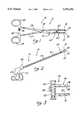
- FIG. 1is a side elevation view of a clamping device having a pair of opposing jaws and more specifically an atraumatic occluding device of the present invention
- FIG. 2is a side elevation view of a laparoscopic grasper in an additional embodiment of the invention.
- FIG. 3is a side elevation view of a vascular clip in a further embodiment of the invention.
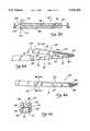
- FIG. 4ais an elevation view of one of the jaws associated with the clamping device of the present invention.
- FIG. 4bis a top plan view of the jaw illustrated in FIG. 4a;
- FIG. 4cis a cross section view taken along lines 4c--4c of FIG. 4a;
- FIG. 5ais a top plan view of a jaw insert associated with the present invention.
- FIG. 5bis an axial cross section view taken along lines 5b--5b of FIG. 5a;
- FIG. 5cis a radial cross section view taken along lines 5c--5c of FIG. 5b;
- FIG. 6ais a side elevation view illustrating an insert being mounted on a clamping jaw associated with the present invention
- FIG. 6bis a side elevation view of the insert mounted in an operative position on the associated jaw.
- FIG. 6cis a cross section view taken along lines 6c--6c of FIG. 1 and FIG. 6b.
- FIGS. 1, 2 and 3A clamping device is illustrated in FIGS. 1, 2 and 3 and designated generally by the reference numeral 10.
- the device 10is in the form of a vessel occluder 12.
- a similar device 10is illustrated in FIG. 2 in the form of a laparoscopic retractor 14.
- Still a further clamping device 10is illustrated in FIG. 3 in the form of a vessel clip 16.
- clamping devices 10are similar in that they each include a pair of opposing jaws 18 and 19 with an associated insert 20, 22. These jaws 18, 19 and inserts 20, 22 are movable between a proximate position and a spaced position. In the proximate position, the jaws 18, 19 and inserts 20, 22 are closely spaced or contacting to engage a body structure such as an organ or a conduit, for example a vessel 23 as illustrated in FIG. 1. In the released position, the jaws 18, 19 and inserts 20, 22 are spaced, thereby permitting release of the body organ, such as the vessel 23.
- the clamping device 10represented by the occluder 12, retractor 14, and clip 16, are dissimilar in their mechanism for moving the jaws 18 and 19 between the proximate and spaced position.
- a pair of crossing handles 25 and 27pivot at a fulcrum pin 30 and terminate at respective thumb loops 32 and 34.
- a pair of ratchet tabs 36 and 38 associated with the respective handles 25 and 27,provide means for locking the jaws 18 and 19 in a preferred relationship.
- the means for moving the jaws 18, 19functions as a scissors.
- the means for moving the jaws 18, 19includes a longitudinal tube 41 having a distal end 43 and a proximal end 45.
- the jaws 18, 19are disposed at the distal end 43, while the handles 25, 27 are disposed at the proximal end 45.
- One of the jaws 18, 19is attached to a shaft 47 which is axially movable within the longitudinal tube 41.
- the shaft 47is attached to and movable with one of the handles 25 and 27. Operation of the handles 25 and 27 in a scissors fashion, results in movement of the jaws 18 and 19 between the proximate and spaced positions.
- the vessel clip 16 illustrated in FIG. 3can include similar jaws 18, 19.
- the means for moving the jaws 18, 19includes telescoping cylinders 50, 52 each of which is attached to an associated one of the jaws 18, 19. The telescoping movement of these cylinders 50, 52 against the bias of a spring 54 results in relative movement of the jaws 18, 19.
- the dimension of the jaw structurewhich is of particular interest to the present invention is the dimension which occurs in a direction of closure that extends between adjacent points on the opposing jaws 18 and 19.
- this direction of closureextends along a plane 56 which is illustrated in FIG. 4b as a line. It will be understood that if the jaws 18, 19 are curved, this direction of closure will also be curved, but nevertheless will extend between adjacent points on the opposing jaws 18 and 19.
- the jaw 19may include a relatively thick section 61 and a relative thin section 63.
- a distally facing shoulder 65separates the two sections 61 and 63.
- distally facing shoulders 67 and 70separate the two sections 61 and 63.
- the thin section 63is characterized by a longitudinal configuration with a top supporting surface 72 and a bottom opposing surface 74. Side surfaces 76 and 78 are best shown in the cross-sectional view of FIG. 4c.
- a beveled or otherwise reduced surface 81extends from the supporting surface 72 to the opposing surface 74 in a proximal direction.
- the distal tip of the jaw 19tends to form a projection 83 where the surface 81 intersects the supporting surface 72.
- At least one and preferably two recesses 85 and 87can be formed along the side surfaces 76 and 78 in general proximity to the shoulders 65-70, in the manner described in greater detail below. These recesses 85 and 87 function as part of a system for removably attaching the insert 22 to the jaw 19. Importantly, the supporting surface 72 and opposing surface 74 remain continuous and unbroken in this embodiment. Additionally, the recesses can be placed as shown in the relatively thick section 61. As a result, the strength of the jaw in the plane of closure 56 remains unaffected by the recesses 85 and 87 in the side wall 76 and 78, respectively.
- the resulting "I-beam" cross sectionwell-known for its resistance to bending, is best illustrated in the cross sectional view of FIG. 4c.
- the insert 22includes an insert base 90, typically formed from a hard plastic such as polypropylene, and a pad 92, typically formed from an elastomeric material such as latex or thermoplastic elastomer.
- the insert base 90includes a center wall 94 which extends longitudinally between edges 96 and 98.
- a center line 101extends intermediate the edges 96 and 98 and is disposed in the plane of closure 56 when the insert 22 is operatively disposed on the jaw 19.
- the center wall 94has an upwardly facing surface 103 and a downwardly facing surface 105.
- a pair of side walls 110 and 112are also included in the insert base 90. These side walls 110 and 112 extend in a common direction, downwardly in FIG. 5b, from the respective edges 96 and 98 of the center wall 94. Thus, the side walls 110 and 112 are spaced from each other and form with the center wall 94 a channel 114 which extends along the length of the insert 22. This channel 114 is best illustrated in FIG. 5c. At the distal end of the insert base 90, the channel 114 is closed and forms an undercut 116.
- the center wall 94is provided with holes 102 along the center line 101. These holes 102 extend at least a portion of the distance from the upwardly facing surface 103 to the downwardly facing surface 105. In the preferred embodiment illustrated, the holes 102 extend entirely through the center wall 94.
- this pad 92is generally molded onto the upwardly facing surface 103. Since this surface is broken by the holes 102, a portion of the elastomeric material forming the pad 92 flows into the holes 102 thereby assisting in anchoring the elastomeric pad 92 to the base 90 of the insert 22.
- the holes 102also contribute to the elastomeric characteristic of the pad 92.
- the thickness of the elastomeric pad 92is locally increased by the depth of the holes 102. This additional thickness provides an increased degree of softness for the insert 22 thereby contributing to the atraumatic characteristics of the clamping device 10.
- the elastomeric material 92can extend beyond the insert base 90 to form a soft nose 118 at the distal tip of the insert 22 and the distal end of the clamping device 10.
- the side walls 110 and 112can extend beyond the center wall 94 to form respective flanges 121 and 123.
- Inwardly facing projections 125 and 127extend toward each other from the inner surfaces of the respective flanges 121 and 123.
- These projections 125 and 127which take the form of spheres in a preferred embodiment, are part of a detent mechanism 130 which aids in attaching the insert 22 to the jaw 19.
- the mounting of the insert 22 on the associated jaw 19is preferably accomplished as illustrated in FIG. 6a. Initially, the projection 83 at the end of the jaw 19 is seated in the undercut 116 at the end of the channel 114 of the insert 22. The insert 22 is then rotated downwardly until the detent mechanism 130 is actuated to mount the insert 22 in a snap fit relationship on the jaw 19. Initially the projections 125, 127 cause the flanges 121, 123 to spread as they slide along the associated side surfaces 76, 78 of the jaw 19. When these projections 125, 127 reach the recesses 85 and 87, the flanges 121, 123 snap inwardly to seat the jaw 19 into the channel 114 of the insert 22.
- the center wall 94 of the insert 22can be relatively thin in profile since the side walls 110, 112 can be relied on to maintain the structural rigidity of the base 90. And while the side walls 110, 112 maintain the structural integrity of the insert 22, they are positioned to extend away from the elastomeric pad 92. Accordingly, they make no contribution to the thickness of the jaw/insert combination along the plane of closure 56.
- This profileis further reduced by permitting the elastomeric material of the pad 92 to extend through the center wall 94 to the supporting surface 72 of the jaw 19. Given this additional thickness for the pad 92, substantial elastomeric properties can be achieved with only a thin layer of the pad 92 extending beyond the upwardly facing surface 103 of the center wall 94.
- the resulting low profile associated with the clamping device 10will be particularly appreciated in those surgical environments which do not provide an abundance of space.
- the clamping device 10such as the retractor 14 illustrated in FIG. 2 can be provided with the low profile inserts 20 and 22 in order to provide atraumatic clamping.
- the detent mechanism 130can be modified so that the projections 125, 127 and recesses, 85, 87 are reversed. This would add additional material to the jaw 19 even further enhancing the structural integrity of this element.
- Other forms of projections and recessescan be used to attach the inserts 20, 22 to the associated jaws 18, 19. As long as any recesses, such as the recesses 85 and 87, are formed along the side surfaces 76, 78, the "I-beam" cross section of the jaw 19 will not be sacrificed.
- the base 90 of the insert 22can be formed from any material providing some degree of rigidity for the insert 22 as well as also a degree of flexibility as required by the attachment mechanism, such as the detent mechanism 130. It will be apparent that the elastomeric material forming the pad 92 can also vary considerably. The elastomeric properties of course contribute to the atraumatic characteristics of the inserts 20, 22, but other materials such as fibers can also achieve this advantage.
- the pad 92can also be molded to any base, such as the base 90, having a profile which facilitates use of the clamping device 10 in a particular environment.
- the configuration of the center wall 94 of the insert 22can also vary considerably. Since this wall 94 is relied on primarily to support the pad 92 and to form the channel 114 with the side walls 110, 112, its shape and thickness can vary significantly with different embodiments. Also, the formation of the holes 102 in various sizes and shapes may enhance the atraumatic and low profile characteristics of a particular construction.
Landscapes
- Health & Medical Sciences (AREA)
- Surgery (AREA)
- Life Sciences & Earth Sciences (AREA)
- Heart & Thoracic Surgery (AREA)
- Molecular Biology (AREA)
- Veterinary Medicine (AREA)
- Engineering & Computer Science (AREA)
- Biomedical Technology (AREA)
- Public Health (AREA)
- Medical Informatics (AREA)
- Nuclear Medicine, Radiotherapy & Molecular Imaging (AREA)
- Animal Behavior & Ethology (AREA)
- General Health & Medical Sciences (AREA)
- Reproductive Health (AREA)
- Vascular Medicine (AREA)
- Ophthalmology & Optometry (AREA)
- Surgical Instruments (AREA)
Abstract
Description
Claims (18)
Priority Applications (7)
| Application Number | Priority Date | Filing Date | Title |
|---|---|---|---|
| US08/324,418US5591182A (en) | 1994-10-17 | 1994-10-17 | Atraumatic surgical clamping instrument |
| EP95937547AEP0786961B1 (en) | 1994-10-17 | 1995-10-10 | Atraumatic surgical clamping instrument |
| CA002202547ACA2202547C (en) | 1994-10-17 | 1995-10-10 | Atraumatic surgical clamping instrument |
| JP51346796AJP3662930B2 (en) | 1994-10-17 | 1995-10-10 | Atraumatic surgical clamp instrument |
| DE69531062TDE69531062T2 (en) | 1994-10-17 | 1995-10-10 | ATRAUMATIC SURGICAL CLAMPING INSTRUMENT |
| PCT/US1995/013506WO1996011635A1 (en) | 1994-10-17 | 1995-10-10 | Atraumatic surgical clamping instrument |
| JP2004379472AJP2005095678A (en) | 1994-10-17 | 2004-12-28 | Atraumatic surgical clamping instrument |
Applications Claiming Priority (1)
| Application Number | Priority Date | Filing Date | Title |
|---|---|---|---|
| US08/324,418US5591182A (en) | 1994-10-17 | 1994-10-17 | Atraumatic surgical clamping instrument |
Publications (1)
| Publication Number | Publication Date |
|---|---|
| US5591182Atrue US5591182A (en) | 1997-01-07 |
Family
ID=23263495
Family Applications (1)
| Application Number | Title | Priority Date | Filing Date |
|---|---|---|---|
| US08/324,418Expired - LifetimeUS5591182A (en) | 1994-10-17 | 1994-10-17 | Atraumatic surgical clamping instrument |
Country Status (5)
| Country | Link |
|---|---|
| US (1) | US5591182A (en) |
| EP (1) | EP0786961B1 (en) |
| JP (2) | JP3662930B2 (en) |
| DE (1) | DE69531062T2 (en) |
| WO (1) | WO1996011635A1 (en) |
Cited By (36)
| Publication number | Priority date | Publication date | Assignee | Title |
|---|---|---|---|---|
| US5906630A (en)* | 1998-06-30 | 1999-05-25 | Boston Scientific Limited | Eccentric surgical forceps |
| US6007552A (en)* | 1997-12-18 | 1999-12-28 | Minumys | Vascular clamps and surgical retractors with directional filaments for tissue engagement |
| WO2000078233A1 (en)* | 1999-06-21 | 2000-12-28 | Novare Surgical Systems, Inc. | Surgical clamp with replaceable clamp members |
| US6214023B1 (en) | 1999-06-21 | 2001-04-10 | Ethicon Endo-Surgery, Inc. | Ultrasonic surgical instrument with removable clamp arm |
| US6228104B1 (en) | 1999-06-18 | 2001-05-08 | Novare Surgical Systems, Inc. | Surgical clamp having replaceable pad |
| US6273902B1 (en) | 1999-06-18 | 2001-08-14 | Novare Surgical Systems, Inc. | Surgical clamp having replaceable pad |
| US6299621B1 (en) | 1999-06-18 | 2001-10-09 | Novare Surgical Systems, Inc. | Surgical clamp pads with elastomer impregnated mesh |
| WO2001043623A3 (en)* | 1999-12-03 | 2002-02-14 | Applied Med Resources | Vessel occlusion clamp |
| US6387112B1 (en) | 1999-06-18 | 2002-05-14 | Novare Surgical Systems, Inc. | Surgical clamp having replaceable pad |
| US6579304B1 (en) | 1997-02-03 | 2003-06-17 | Applied Medical Resources Corporation | Surgical clamp with improved traction |
| US20030181932A1 (en)* | 2002-03-21 | 2003-09-25 | Terrence Buelna | Surgical clamp pads with deflecting elements |
| US6719766B1 (en) | 2000-08-24 | 2004-04-13 | Novare Surgical Systems, Inc. | Surgical clamp pads having surface overlay |
| US20040143276A1 (en)* | 2003-01-22 | 2004-07-22 | Sturtz Karrie L. | Surgical clamp inserts with micro-tractive surfaces |
| US20050101991A1 (en)* | 2003-11-12 | 2005-05-12 | Applied Medical Resources Corporation | Overmolded grasper jaw |
| US20050240219A1 (en)* | 2004-04-22 | 2005-10-27 | Henry Kahle | Peripheral vascular occlusion devices |
| US20060161182A1 (en)* | 2005-01-19 | 2006-07-20 | Applied Medical Resources Corporation | Single fire vascular clip applier with disposable jaw |
| US20060247678A1 (en)* | 2005-04-08 | 2006-11-02 | Weisenburgh William B Ii | Surgical instrument system |
| US20070179526A1 (en)* | 1997-02-03 | 2007-08-02 | Hart Charles C | Surgical clamp with improved traction |
| US20090062618A1 (en)* | 2007-08-29 | 2009-03-05 | Ethicon Endo-Surgery, Inc. | Tissue retractors |
| US20090137877A1 (en)* | 2007-11-26 | 2009-05-28 | Ethicon Endo-Surgery, Inc. | Tissue retractors |
| US20090245754A1 (en)* | 2000-02-11 | 2009-10-01 | Datcard Systems, Inc. | System and method for producing medical image data onto portable digital recording media |
| US20100228096A1 (en)* | 2009-03-06 | 2010-09-09 | Ethicon Endo-Surgery, Inc. | Methods and devices for providing access into a body cavity |
| US20100228090A1 (en)* | 2009-03-06 | 2010-09-09 | Ethicon Endo-Surgery, Inc. | Methods and devices for providing access into a body cavity |
| US20100249521A1 (en)* | 2009-03-31 | 2010-09-30 | Shelton Iv Frederick E | Access Device Including Retractor And Insert |
| US20100249525A1 (en)* | 2009-03-31 | 2010-09-30 | Ethicon Endo-Surgery, Inc. | Devices and methods for providing access into a body cavity |
| US20100261975A1 (en)* | 2009-03-06 | 2010-10-14 | Ethicon Endo-Surgery, Inc. | Methods and devices for accessing a body cavity |
| US20110028793A1 (en)* | 2009-07-30 | 2011-02-03 | Ethicon Endo-Surgery, Inc. | Methods and devices for providing access into a body cavity |
| US20110066001A1 (en)* | 2009-03-31 | 2011-03-17 | Shelton Iv Frederick E | Access Method With Insert |
| US8460337B2 (en) | 2010-06-09 | 2013-06-11 | Ethicon Endo-Surgery, Inc. | Selectable handle biasing |
| US8491624B2 (en) | 2010-06-02 | 2013-07-23 | Covidien Lp | Apparatus for performing an electrosurgical procedure |
| US8562592B2 (en) | 2010-05-07 | 2013-10-22 | Ethicon Endo-Surgery, Inc. | Compound angle laparoscopic methods and devices |
| US9226760B2 (en) | 2010-05-07 | 2016-01-05 | Ethicon Endo-Surgery, Inc. | Laparoscopic devices with flexible actuation mechanisms |
| US9333001B2 (en) | 2009-10-08 | 2016-05-10 | Ethicon Endo-Surgery, Inc. | Articulable laparoscopic instrument |
| US9499318B2 (en) | 2014-08-21 | 2016-11-22 | Cook Medical Technologies Llc | System and method for containment and organization of medical wire |
| US9664213B2 (en) | 2014-08-21 | 2017-05-30 | Cook Medical Technologies Llc | System for containment and organization of medical wire |
| US11596428B2 (en) | 2018-11-15 | 2023-03-07 | Applied Medical Resources Corporation | Laparoscopic grasper with force-limiting grasping mechanism |
Families Citing this family (22)
| Publication number | Priority date | Publication date | Assignee | Title |
|---|---|---|---|---|
| US6050996A (en)* | 1997-11-12 | 2000-04-18 | Sherwood Services Ag | Bipolar electrosurgical instrument with replaceable electrodes |
| US7364577B2 (en) | 2002-02-11 | 2008-04-29 | Sherwood Services Ag | Vessel sealing system |
| CA2500569A1 (en)* | 2002-10-04 | 2004-04-22 | Sherwood Services Ag | Electrosurgical instrument for sealing vessels |
| US7276068B2 (en) | 2002-10-04 | 2007-10-02 | Sherwood Services Ag | Vessel sealing instrument with electrical cutting mechanism |
| US7799026B2 (en) | 2002-11-14 | 2010-09-21 | Covidien Ag | Compressible jaw configuration with bipolar RF output electrodes for soft tissue fusion |
| US7160299B2 (en) | 2003-05-01 | 2007-01-09 | Sherwood Services Ag | Method of fusing biomaterials with radiofrequency energy |
| US9848938B2 (en) | 2003-11-13 | 2017-12-26 | Covidien Ag | Compressible jaw configuration with bipolar RF output electrodes for soft tissue fusion |
| US7367976B2 (en) | 2003-11-17 | 2008-05-06 | Sherwood Services Ag | Bipolar forceps having monopolar extension |
| US7722607B2 (en) | 2005-09-30 | 2010-05-25 | Covidien Ag | In-line vessel sealer and divider |
| CA2561034C (en) | 2005-09-30 | 2014-12-09 | Sherwood Services Ag | Flexible endoscopic catheter with an end effector for coagulating and transfecting tissue |
| US8016827B2 (en) | 2008-10-09 | 2011-09-13 | Tyco Healthcare Group Lp | Apparatus, system, and method for performing an electrosurgical procedure |
| US8114122B2 (en) | 2009-01-13 | 2012-02-14 | Tyco Healthcare Group Lp | Apparatus, system, and method for performing an electrosurgical procedure |
| US8187273B2 (en) | 2009-05-07 | 2012-05-29 | Tyco Healthcare Group Lp | Apparatus, system, and method for performing an electrosurgical procedure |
| US8133254B2 (en) | 2009-09-18 | 2012-03-13 | Tyco Healthcare Group Lp | In vivo attachable and detachable end effector assembly and laparoscopic surgical instrument and methods therefor |
| US8112871B2 (en) | 2009-09-28 | 2012-02-14 | Tyco Healthcare Group Lp | Method for manufacturing electrosurgical seal plates |
| US8858553B2 (en) | 2010-01-29 | 2014-10-14 | Covidien Lp | Dielectric jaw insert for electrosurgical end effector |
| US8430877B2 (en) | 2010-06-02 | 2013-04-30 | Covidien Lp | Apparatus for performing an electrosurgical procedure |
| US9113940B2 (en) | 2011-01-14 | 2015-08-25 | Covidien Lp | Trigger lockout and kickback mechanism for surgical instruments |
| US9844384B2 (en) | 2011-07-11 | 2017-12-19 | Covidien Lp | Stand alone energy-based tissue clips |
| US20150324317A1 (en) | 2014-05-07 | 2015-11-12 | Covidien Lp | Authentication and information system for reusable surgical instruments |
| US10213250B2 (en) | 2015-11-05 | 2019-02-26 | Covidien Lp | Deployment and safety mechanisms for surgical instruments |
| US11844562B2 (en) | 2020-03-23 | 2023-12-19 | Covidien Lp | Electrosurgical forceps for grasping, treating, and/or dividing tissue |
Citations (15)
| Publication number | Priority date | Publication date | Assignee | Title |
|---|---|---|---|---|
| US1556755A (en)* | 1925-03-07 | 1925-10-13 | Peter M Burman | Multiform tool |
| US2743726A (en)* | 1953-05-28 | 1956-05-01 | Herman R Grieshaber | Surgical instrument |
| US3515139A (en)* | 1966-08-29 | 1970-06-02 | Codman & Shurtleff | Atraumatic clamp |
| US3746002A (en)* | 1971-04-29 | 1973-07-17 | J Haller | Atraumatic surgical clamp |
| US4120302A (en)* | 1976-10-08 | 1978-10-17 | American Hospital Supply Corporation | Disposable pads for surgical instruments |
| US4499798A (en)* | 1983-05-09 | 1985-02-19 | Miskiewicz Leonard A | Removable cap members for pliers |
| US4727876A (en)* | 1984-09-26 | 1988-03-01 | Michael Porat | Medical forceps or clamps |
| US4821719A (en)* | 1984-12-03 | 1989-04-18 | Fogarty Thomas J | Cohesive-adhesive atraumatic clamp |
| US4834090A (en)* | 1987-03-02 | 1989-05-30 | Moore J Paul | Suture boot |
| US4988355A (en)* | 1990-01-16 | 1991-01-29 | Leveen Eric G | Arterial clamp |
| US5009657A (en)* | 1989-12-14 | 1991-04-23 | Mohammed S. Jahanger | Umbilical cord cutting and clamping device |
| US5242458A (en)* | 1991-10-15 | 1993-09-07 | Ethicon, Inc. | Suture needle holder for endoscopic use |
| US5250072A (en)* | 1990-12-10 | 1993-10-05 | Jain Krishna M | Surgical clamp jaw cover |
| US5258005A (en)* | 1991-12-13 | 1993-11-02 | Unisurge, Inc. | Atraumatic grasping device for laparoscopic surgery |
| US5282812A (en)* | 1991-07-10 | 1994-02-01 | Suarez Jr Luis | Clamp for use in vascular surgery |
Family Cites Families (2)
| Publication number | Priority date | Publication date | Assignee | Title |
|---|---|---|---|---|
| US3503398A (en)* | 1965-09-10 | 1970-03-31 | American Hospital Supply Corp | Atraumatic clamp for vascular surgery |
| AU676208B2 (en)* | 1992-11-18 | 1997-03-06 | Ethicon Inc. | Atraumatic endoscopic apparatus |
- 1994
- 1994-10-17USUS08/324,418patent/US5591182A/ennot_activeExpired - Lifetime
- 1995
- 1995-10-10DEDE69531062Tpatent/DE69531062T2/ennot_activeExpired - Lifetime
- 1995-10-10WOPCT/US1995/013506patent/WO1996011635A1/enactiveIP Right Grant
- 1995-10-10EPEP95937547Apatent/EP0786961B1/ennot_activeExpired - Lifetime
- 1995-10-10JPJP51346796Apatent/JP3662930B2/ennot_activeExpired - Lifetime
- 2004
- 2004-12-28JPJP2004379472Apatent/JP2005095678A/enactivePending
Patent Citations (15)
| Publication number | Priority date | Publication date | Assignee | Title |
|---|---|---|---|---|
| US1556755A (en)* | 1925-03-07 | 1925-10-13 | Peter M Burman | Multiform tool |
| US2743726A (en)* | 1953-05-28 | 1956-05-01 | Herman R Grieshaber | Surgical instrument |
| US3515139A (en)* | 1966-08-29 | 1970-06-02 | Codman & Shurtleff | Atraumatic clamp |
| US3746002A (en)* | 1971-04-29 | 1973-07-17 | J Haller | Atraumatic surgical clamp |
| US4120302A (en)* | 1976-10-08 | 1978-10-17 | American Hospital Supply Corporation | Disposable pads for surgical instruments |
| US4499798A (en)* | 1983-05-09 | 1985-02-19 | Miskiewicz Leonard A | Removable cap members for pliers |
| US4727876A (en)* | 1984-09-26 | 1988-03-01 | Michael Porat | Medical forceps or clamps |
| US4821719A (en)* | 1984-12-03 | 1989-04-18 | Fogarty Thomas J | Cohesive-adhesive atraumatic clamp |
| US4834090A (en)* | 1987-03-02 | 1989-05-30 | Moore J Paul | Suture boot |
| US5009657A (en)* | 1989-12-14 | 1991-04-23 | Mohammed S. Jahanger | Umbilical cord cutting and clamping device |
| US4988355A (en)* | 1990-01-16 | 1991-01-29 | Leveen Eric G | Arterial clamp |
| US5250072A (en)* | 1990-12-10 | 1993-10-05 | Jain Krishna M | Surgical clamp jaw cover |
| US5282812A (en)* | 1991-07-10 | 1994-02-01 | Suarez Jr Luis | Clamp for use in vascular surgery |
| US5242458A (en)* | 1991-10-15 | 1993-09-07 | Ethicon, Inc. | Suture needle holder for endoscopic use |
| US5258005A (en)* | 1991-12-13 | 1993-11-02 | Unisurge, Inc. | Atraumatic grasping device for laparoscopic surgery |
Cited By (92)
| Publication number | Priority date | Publication date | Assignee | Title |
|---|---|---|---|---|
| US8092473B2 (en)* | 1997-02-03 | 2012-01-10 | Applied Medical Resources Corporation | Surgical clamp with improved traction |
| US6579304B1 (en) | 1997-02-03 | 2003-06-17 | Applied Medical Resources Corporation | Surgical clamp with improved traction |
| US20070179526A1 (en)* | 1997-02-03 | 2007-08-02 | Hart Charles C | Surgical clamp with improved traction |
| US6312445B1 (en) | 1997-12-18 | 2001-11-06 | Novare Surgical Systems, Inc. | Vascular clamps and surgical retractors with directional filaments for tissue engagement |
| US6461368B2 (en) | 1997-12-18 | 2002-10-08 | Novare Surgical Systems, Inc. | Vascular clamps and surgical retractors with directional filaments for tissue engagement |
| US6007552A (en)* | 1997-12-18 | 1999-12-28 | Minumys | Vascular clamps and surgical retractors with directional filaments for tissue engagement |
| US6165186A (en)* | 1997-12-18 | 2000-12-26 | Novare Surgical Systems, Inc. | Vascular clamps and surgical retractors with directional filaments for tissue engagement |
| US5906630A (en)* | 1998-06-30 | 1999-05-25 | Boston Scientific Limited | Eccentric surgical forceps |
| US6692514B2 (en) | 1999-06-18 | 2004-02-17 | Novare Surgical Systems, Inc. | Surgical clamp having replaceable pad |
| US6387112B1 (en) | 1999-06-18 | 2002-05-14 | Novare Surgical Systems, Inc. | Surgical clamp having replaceable pad |
| US6273902B1 (en) | 1999-06-18 | 2001-08-14 | Novare Surgical Systems, Inc. | Surgical clamp having replaceable pad |
| US6228104B1 (en) | 1999-06-18 | 2001-05-08 | Novare Surgical Systems, Inc. | Surgical clamp having replaceable pad |
| US6530942B2 (en) | 1999-06-18 | 2003-03-11 | Novare Surgical Systems, Inc. | Surgical clamp having replaceable pad |
| US6299621B1 (en) | 1999-06-18 | 2001-10-09 | Novare Surgical Systems, Inc. | Surgical clamp pads with elastomer impregnated mesh |
| US6558408B1 (en) | 1999-06-18 | 2003-05-06 | Novare Surgical Systems, Inc. | Surgical clamp having replaceable pad |
| WO2000078233A1 (en)* | 1999-06-21 | 2000-12-28 | Novare Surgical Systems, Inc. | Surgical clamp with replaceable clamp members |
| US6214023B1 (en) | 1999-06-21 | 2001-04-10 | Ethicon Endo-Surgery, Inc. | Ultrasonic surgical instrument with removable clamp arm |
| US6293954B1 (en) | 1999-06-21 | 2001-09-25 | Novare Surgical Systems, Inc. | Surgical clamp with replaceable clamp members |
| US20020183770A1 (en)* | 1999-12-03 | 2002-12-05 | Anderson Steven R. | Vessel occlusion clamp |
| EP1233708A4 (en)* | 1999-12-03 | 2006-04-26 | Applied Med Resources | Vessel occlusion clamp |
| US8740933B2 (en) | 1999-12-03 | 2014-06-03 | Applied Medical Resources Corporation | Vessel occlusion clamp |
| US20050251184A1 (en)* | 1999-12-03 | 2005-11-10 | Applied Medical Resources Corporation | Vessel occlusion clamp |
| US6932825B2 (en)* | 1999-12-03 | 2005-08-23 | Applied Medical Resources Corporation | Vessel occlusion clamp |
| US7744623B2 (en) | 1999-12-03 | 2010-06-29 | Applied Medical Resources Corporation | Vessel occlusion clamp |
| WO2001043623A3 (en)* | 1999-12-03 | 2002-02-14 | Applied Med Resources | Vessel occlusion clamp |
| US20090245754A1 (en)* | 2000-02-11 | 2009-10-01 | Datcard Systems, Inc. | System and method for producing medical image data onto portable digital recording media |
| US6719766B1 (en) | 2000-08-24 | 2004-04-13 | Novare Surgical Systems, Inc. | Surgical clamp pads having surface overlay |
| US20040167552A1 (en)* | 2000-08-24 | 2004-08-26 | Novare Surgical Systems, Inc. | Surgical clamp pads having surface overlay |
| US20030181932A1 (en)* | 2002-03-21 | 2003-09-25 | Terrence Buelna | Surgical clamp pads with deflecting elements |
| US6942676B2 (en) | 2002-03-21 | 2005-09-13 | Novare Surgical Systems, Inc. | Surgical clamp pads with deflecting elements |
| US6821284B2 (en) | 2003-01-22 | 2004-11-23 | Novare Surgical Systems, Inc. | Surgical clamp inserts with micro-tractive surfaces |
| US20040143276A1 (en)* | 2003-01-22 | 2004-07-22 | Sturtz Karrie L. | Surgical clamp inserts with micro-tractive surfaces |
| AU2004289336B2 (en)* | 2003-11-12 | 2010-07-29 | Applied Medical Resources Corporation | Surgical instrument having jaw spines |
| US7494501B2 (en)* | 2003-11-12 | 2009-02-24 | Applied Medical Resources Corporation | Overmolded grasper jaw |
| US9161770B2 (en) | 2003-11-12 | 2015-10-20 | Applied Medical Resources Corporation | Overmolded grasper jaw |
| EP2889011A1 (en)* | 2003-11-12 | 2015-07-01 | Applied Medical Resources Corporation | Overmolded grasper jaw |
| US20050101991A1 (en)* | 2003-11-12 | 2005-05-12 | Applied Medical Resources Corporation | Overmolded grasper jaw |
| US8545534B2 (en) | 2003-11-12 | 2013-10-01 | Applied Medical Resources Corporation | Overmolded grasper jaw |
| WO2005046491A1 (en)* | 2003-11-12 | 2005-05-26 | Applied Medical Resources Corporation | Overmolded grasper jaw |
| US20090131975A1 (en)* | 2003-11-12 | 2009-05-21 | Applied Medical Resources Corporation | Overmolded grasper jaw |
| US20050240219A1 (en)* | 2004-04-22 | 2005-10-27 | Henry Kahle | Peripheral vascular occlusion devices |
| WO2005107613A1 (en)* | 2004-04-22 | 2005-11-17 | Applied Medical Resources Corporation | Peripheral vascular occlusion devices |
| US20060161182A1 (en)* | 2005-01-19 | 2006-07-20 | Applied Medical Resources Corporation | Single fire vascular clip applier with disposable jaw |
| US7842045B2 (en) | 2005-01-19 | 2010-11-30 | Applied Medical Resources Corporation | Single fire vascular clip applier with disposable jaw |
| US20060247500A1 (en)* | 2005-04-08 | 2006-11-02 | Voegele James W | Surgical access device |
| US20060247673A1 (en)* | 2005-04-08 | 2006-11-02 | Voegele James W | Multi-port laparoscopic access device |
| US20060247516A1 (en)* | 2005-04-08 | 2006-11-02 | Hess Christopher J | Tissue marker and method for use |
| US20060247586A1 (en)* | 2005-04-08 | 2006-11-02 | Voegele James W | Intra-abdominal storage device |
| US20100228093A1 (en)* | 2005-04-08 | 2010-09-09 | Voegele James W | Tissue retraction device |
| US20060270911A1 (en)* | 2005-04-08 | 2006-11-30 | Voegele James W | Tissue retraction device |
| US20060247678A1 (en)* | 2005-04-08 | 2006-11-02 | Weisenburgh William B Ii | Surgical instrument system |
| US20100030032A1 (en)* | 2005-04-08 | 2010-02-04 | Voegele James W | Access device |
| US20060258899A1 (en)* | 2005-04-08 | 2006-11-16 | Gill Robert P | Tissue suspension device |
| US8545450B2 (en) | 2005-04-08 | 2013-10-01 | Ethicon Endo-Surgery, Inc. | Multi-port laparoscopic access device |
| US7837612B2 (en) | 2005-04-08 | 2010-11-23 | Ethicon Endo-Surgery, Inc. | Tissue suspension device |
| US8517995B2 (en) | 2005-04-08 | 2013-08-27 | Ethicon Endo-Surgery, Inc. | Access device |
| US20100249516A1 (en)* | 2006-04-05 | 2010-09-30 | Shelton Iv Frederick E | Access Device |
| US9005116B2 (en) | 2006-04-05 | 2015-04-14 | Ethicon Endo-Surgery, Inc. | Access device |
| US8465515B2 (en) | 2007-08-29 | 2013-06-18 | Ethicon Endo-Surgery, Inc. | Tissue retractors |
| US20090062618A1 (en)* | 2007-08-29 | 2009-03-05 | Ethicon Endo-Surgery, Inc. | Tissue retractors |
| US8517931B2 (en) | 2007-11-26 | 2013-08-27 | Ethicon Endo-Surgery, Inc. | Tissue retractors |
| US20090137877A1 (en)* | 2007-11-26 | 2009-05-28 | Ethicon Endo-Surgery, Inc. | Tissue retractors |
| US20100228096A1 (en)* | 2009-03-06 | 2010-09-09 | Ethicon Endo-Surgery, Inc. | Methods and devices for providing access into a body cavity |
| US20100228090A1 (en)* | 2009-03-06 | 2010-09-09 | Ethicon Endo-Surgery, Inc. | Methods and devices for providing access into a body cavity |
| US20100261975A1 (en)* | 2009-03-06 | 2010-10-14 | Ethicon Endo-Surgery, Inc. | Methods and devices for accessing a body cavity |
| US9737334B2 (en) | 2009-03-06 | 2017-08-22 | Ethicon Llc | Methods and devices for accessing a body cavity |
| US8357085B2 (en) | 2009-03-31 | 2013-01-22 | Ethicon Endo-Surgery, Inc. | Devices and methods for providing access into a body cavity |
| US20110066001A1 (en)* | 2009-03-31 | 2011-03-17 | Shelton Iv Frederick E | Access Method With Insert |
| US20100249520A1 (en)* | 2009-03-31 | 2010-09-30 | Shelton Iv Frederick E | Method Of Surgical Access |
| US20100249525A1 (en)* | 2009-03-31 | 2010-09-30 | Ethicon Endo-Surgery, Inc. | Devices and methods for providing access into a body cavity |
| US20100249521A1 (en)* | 2009-03-31 | 2010-09-30 | Shelton Iv Frederick E | Access Device Including Retractor And Insert |
| US8353824B2 (en) | 2009-03-31 | 2013-01-15 | Ethicon Endo-Surgery, Inc. | Access method with insert |
| US8226553B2 (en) | 2009-03-31 | 2012-07-24 | Ethicon Endo-Surgery, Inc. | Access device with insert |
| US20110028793A1 (en)* | 2009-07-30 | 2011-02-03 | Ethicon Endo-Surgery, Inc. | Methods and devices for providing access into a body cavity |
| US9474540B2 (en) | 2009-10-08 | 2016-10-25 | Ethicon-Endo-Surgery, Inc. | Laparoscopic device with compound angulation |
| US9333001B2 (en) | 2009-10-08 | 2016-05-10 | Ethicon Endo-Surgery, Inc. | Articulable laparoscopic instrument |
| US9226760B2 (en) | 2010-05-07 | 2016-01-05 | Ethicon Endo-Surgery, Inc. | Laparoscopic devices with flexible actuation mechanisms |
| US10206701B2 (en) | 2010-05-07 | 2019-02-19 | Ethicon Llc | Compound angle laparoscopic methods and devices |
| US8562592B2 (en) | 2010-05-07 | 2013-10-22 | Ethicon Endo-Surgery, Inc. | Compound angle laparoscopic methods and devices |
| US9468426B2 (en) | 2010-05-07 | 2016-10-18 | Ethicon Endo-Surgery, Inc. | Compound angle laparoscopic methods and devices |
| US8491624B2 (en) | 2010-06-02 | 2013-07-23 | Covidien Lp | Apparatus for performing an electrosurgical procedure |
| US10136940B2 (en) | 2010-06-02 | 2018-11-27 | Covidien Lp | Apparatus for performing an electrosurgical procedure |
| US9192433B2 (en) | 2010-06-02 | 2015-11-24 | Covidien Lp | Apparatus for performing an electrosurgical procedure |
| US11007006B2 (en) | 2010-06-02 | 2021-05-18 | Covidien Lp | Apparatus for performing an electrosurgical procedure |
| US8460337B2 (en) | 2010-06-09 | 2013-06-11 | Ethicon Endo-Surgery, Inc. | Selectable handle biasing |
| US9499318B2 (en) | 2014-08-21 | 2016-11-22 | Cook Medical Technologies Llc | System and method for containment and organization of medical wire |
| US9664213B2 (en) | 2014-08-21 | 2017-05-30 | Cook Medical Technologies Llc | System for containment and organization of medical wire |
| US10039611B2 (en) | 2014-08-21 | 2018-08-07 | Cook Medical Technologies Llc | System and method for containment and organization of medical wire |
| US10280955B2 (en) | 2014-08-21 | 2019-05-07 | Cook Medical Technologies Llc | System for containment and organization of medical wire |
| US10646299B2 (en) | 2014-08-21 | 2020-05-12 | Cook Medical Technologies Llc | System and method for containment and organization of medical wire |
| US11596428B2 (en) | 2018-11-15 | 2023-03-07 | Applied Medical Resources Corporation | Laparoscopic grasper with force-limiting grasping mechanism |
| US12042165B2 (en) | 2018-11-15 | 2024-07-23 | Applied Medical Resources Corporation | Laparoscopic grasper with force-limiting grasping mechanism |
Also Published As
| Publication number | Publication date |
|---|---|
| JP3662930B2 (en) | 2005-06-22 |
| EP0786961A1 (en) | 1997-08-06 |
| DE69531062T2 (en) | 2003-12-04 |
| JP2005095678A (en) | 2005-04-14 |
| EP0786961B1 (en) | 2003-06-11 |
| WO1996011635A1 (en) | 1996-04-25 |
| DE69531062D1 (en) | 2003-07-17 |
| JPH10509602A (en) | 1998-09-22 |
| EP0786961A4 (en) | 1998-01-14 |
Similar Documents
| Publication | Publication Date | Title |
|---|---|---|
| US5591182A (en) | Atraumatic surgical clamping instrument | |
| US4817604A (en) | Disposable cholangiogram clip | |
| EP1187564B1 (en) | Surgical clamp with replaceable clamp members | |
| US10136898B2 (en) | Narrow profile surgical ligation clip | |
| EP2238925B1 (en) | Surgical access port and associated introducer mechanism | |
| EP0906061B1 (en) | Surgical grasper devices | |
| US8007492B2 (en) | Cannula for receiving surgical instruments | |
| US8048109B2 (en) | Surgical retractor extensions | |
| US7909843B2 (en) | Elongateable surgical port and dilator | |
| US9597114B2 (en) | Expandable surgical access port | |
| US7780688B2 (en) | Spring clip and method for assembling same | |
| US20110224700A1 (en) | Narrow Profile Surgical Ligation Clip | |
| US20020173798A1 (en) | Cannula for receiving surgical instruments | |
| US20030004523A1 (en) | Multi-needle holding device | |
| JP2007044395A (en) | Wound retractor | |
| CA2202547C (en) | Atraumatic surgical clamping instrument | |
| US20030229368A1 (en) | Endoscopic surgical clip | |
| KR20070097714A (en) | Clip for dural suture | |
| JP7695753B1 (en) | Ring-shaped member | |
| WO2021211962A1 (en) | Surgical retractor tool for endoscopic and minimally-invasive surgeries | |
| JPS6041212Y2 (en) | Microsurgery instruments | |
| WO2001058367A1 (en) | Occlusion device | |
| JP2006175047A (en) | Variable Elevatorium |
Legal Events
| Date | Code | Title | Description |
|---|---|---|---|
| AS | Assignment | Owner name:APPLIED MEDICAL RESOURCES CORP., CALIFORNIA Free format text:ASSIGNMENT OF ASSIGNORS INTEREST;ASSIGNOR:JOHNSON, GARY M.;REEL/FRAME:007202/0379 Effective date:19941013 | |
| STCF | Information on status: patent grant | Free format text:PATENTED CASE | |
| FEPP | Fee payment procedure | Free format text:PAYOR NUMBER ASSIGNED (ORIGINAL EVENT CODE: ASPN); ENTITY STATUS OF PATENT OWNER: LARGE ENTITY | |
| REMI | Maintenance fee reminder mailed | ||
| FPAY | Fee payment | Year of fee payment:4 | |
| SULP | Surcharge for late payment | ||
| FPAY | Fee payment | Year of fee payment:8 | |
| FEPP | Fee payment procedure | Free format text:PAT HOLDER NO LONGER CLAIMS SMALL ENTITY STATUS, ENTITY STATUS SET TO UNDISCOUNTED (ORIGINAL EVENT CODE: STOL); ENTITY STATUS OF PATENT OWNER: LARGE ENTITY | |
| FPAY | Fee payment | Year of fee payment:12 | |
| REMI | Maintenance fee reminder mailed | ||
| AS | Assignment | Owner name:CITIBANK, N.A., TEXAS Free format text:SECURITY AGREEMENT;ASSIGNOR:APPLIED MEDICAL RESOURCES CORPORATION;REEL/FRAME:028115/0276 Effective date:20120417 | |
| AS | Assignment | Owner name:APPLIED MEDICAL RESOURCES CORPORATION, CALIFORNIA Free format text:RELEASE BY SECURED PARTY;ASSIGNOR:CITIBANK N.A., AS ADMINISTRATIVE AGENT;REEL/FRAME:066795/0595 Effective date:20240129 |