US5591137A - Hemostasis valve with locking seal - Google Patents
Hemostasis valve with locking sealDownload PDFInfo
- Publication number
- US5591137A US5591137AUS08/502,753US50275395AUS5591137AUS 5591137 AUS5591137 AUS 5591137AUS 50275395 AUS50275395 AUS 50275395AUS 5591137 AUS5591137 AUS 5591137A
- Authority
- US
- United States
- Prior art keywords
- compression chamber
- proximal end
- seal
- distal end
- shaft
- Prior art date
- Legal status (The legal status is an assumption and is not a legal conclusion. Google has not performed a legal analysis and makes no representation as to the accuracy of the status listed.)
- Expired - Lifetime
Links
- 230000023597hemostasisEffects0.000titleclaimsdescription18
- 230000006835compressionEffects0.000claimsabstractdescription136
- 238000007906compressionMethods0.000claimsabstractdescription136
- 238000007789sealingMethods0.000claimsdescription37
- 210000000748cardiovascular systemAnatomy0.000claimsdescription15
- 230000008878couplingEffects0.000claimsdescription11
- 238000010168coupling processMethods0.000claimsdescription11
- 238000005859coupling reactionMethods0.000claimsdescription11
- 210000001124body fluidAnatomy0.000claimsdescription4
- 239000004033plasticSubstances0.000claimsdescription4
- 229920003023plasticPolymers0.000claimsdescription4
- -1polytetrafluoroethylenePolymers0.000claimsdescription4
- 229920001343polytetrafluoroethylenePolymers0.000claimsdescription4
- 239000004810polytetrafluoroethyleneSubstances0.000claimsdescription4
- 229920001971elastomerPolymers0.000claimsdescription3
- 229920001296polysiloxanePolymers0.000claimsdescription3
- 239000005060rubberSubstances0.000claimsdescription3
- 239000004417polycarbonateSubstances0.000claimsdescription2
- 229920000515polycarbonatePolymers0.000claimsdescription2
- 230000002526effect on cardiovascular systemEffects0.000claims6
- 239000010839body fluidSubstances0.000claims2
- 230000007704transitionEffects0.000description15
- 239000008280bloodSubstances0.000description14
- 210000004369bloodAnatomy0.000description14
- 239000012530fluidSubstances0.000description13
- 238000012546transferMethods0.000description10
- 239000000463materialSubstances0.000description9
- 239000000853adhesiveSubstances0.000description7
- 230000001070adhesive effectEffects0.000description7
- 238000004891communicationMethods0.000description6
- 230000000295complement effectEffects0.000description4
- 238000003780insertionMethods0.000description4
- 230000037431insertionEffects0.000description4
- 230000000153supplemental effectEffects0.000description4
- 230000000903blocking effectEffects0.000description3
- 210000004204blood vesselAnatomy0.000description3
- 238000006073displacement reactionMethods0.000description3
- 238000000034methodMethods0.000description3
- 230000036961partial effectEffects0.000description3
- 230000000740bleeding effectEffects0.000description2
- 239000000314lubricantSubstances0.000description2
- 230000008569processEffects0.000description2
- 238000000926separation methodMethods0.000description2
- 238000001356surgical procedureMethods0.000description2
- 210000003462veinAnatomy0.000description2
- 208000030507AIDSDiseases0.000description1
- 208000019838Blood diseaseDiseases0.000description1
- 244000043261Hevea brasiliensisSpecies0.000description1
- 229920006362Teflon®Polymers0.000description1
- DHKHKXVYLBGOIT-UHFFFAOYSA-Nacetaldehyde Diethyl AcetalNatural productsCCOC(C)OCCDHKHKXVYLBGOIT-UHFFFAOYSA-N0.000description1
- 125000002777acetyl groupChemical class[H]C([H])([H])C(*)=O0.000description1
- 238000002399angioplastyMethods0.000description1
- 238000013459approachMethods0.000description1
- 238000010009beatingMethods0.000description1
- 238000011109contaminationMethods0.000description1
- 230000003247decreasing effectEffects0.000description1
- 238000013461designMethods0.000description1
- 229940079593drugDrugs0.000description1
- 239000003814drugSubstances0.000description1
- 230000000694effectsEffects0.000description1
- 238000005516engineering processMethods0.000description1
- HQQADJVZYDDRJT-UHFFFAOYSA-Nethene;prop-1-eneChemical groupC=C.CC=CHQQADJVZYDDRJT-UHFFFAOYSA-N0.000description1
- 208000014951hematologic diseaseDiseases0.000description1
- 208000018706hematopoietic system diseaseDiseases0.000description1
- 230000003993interactionEffects0.000description1
- 230000002452interceptive effectEffects0.000description1
- 230000000670limiting effectEffects0.000description1
- 229920002529medical grade siliconePolymers0.000description1
- 238000000465mouldingMethods0.000description1
- 229920003052natural elastomerPolymers0.000description1
- 229920001194natural rubberPolymers0.000description1
- 230000002829reductive effectEffects0.000description1
- 230000008439repair processEffects0.000description1
- 239000012858resilient materialSubstances0.000description1
Images


Classifications
- A—HUMAN NECESSITIES
- A61—MEDICAL OR VETERINARY SCIENCE; HYGIENE
- A61M—DEVICES FOR INTRODUCING MEDIA INTO, OR ONTO, THE BODY; DEVICES FOR TRANSDUCING BODY MEDIA OR FOR TAKING MEDIA FROM THE BODY; DEVICES FOR PRODUCING OR ENDING SLEEP OR STUPOR
- A61M39/00—Tubes, tube connectors, tube couplings, valves, access sites or the like, specially adapted for medical use
- A61M39/02—Access sites
- A61M39/06—Haemostasis valves, i.e. gaskets sealing around a needle, catheter or the like, closing on removal thereof
- A61M39/0613—Haemostasis valves, i.e. gaskets sealing around a needle, catheter or the like, closing on removal thereof with means for adjusting the seal opening or pressure
- A—HUMAN NECESSITIES
- A61—MEDICAL OR VETERINARY SCIENCE; HYGIENE
- A61M—DEVICES FOR INTRODUCING MEDIA INTO, OR ONTO, THE BODY; DEVICES FOR TRANSDUCING BODY MEDIA OR FOR TAKING MEDIA FROM THE BODY; DEVICES FOR PRODUCING OR ENDING SLEEP OR STUPOR
- A61M39/00—Tubes, tube connectors, tube couplings, valves, access sites or the like, specially adapted for medical use
- A61M39/02—Access sites
- A61M39/06—Haemostasis valves, i.e. gaskets sealing around a needle, catheter or the like, closing on removal thereof
- A61M2039/0673—Haemostasis valves, i.e. gaskets sealing around a needle, catheter or the like, closing on removal thereof comprising means actively pressing on the device passing through the seal, e.g. inflatable seals, diaphragms, clamps
Definitions
- the present inventionrelates to valves and, more specifically, to hemostasis valves.
- a cathetercan be introduced into the body of a patient and used to deliver fluid, such as medication, directly to a predetermined location within the cardiovascular system.
- Catheterscan also be used for exploratory surgery and for removing tissue samples within a body.
- One increasingly common use for cathetersis in the placement of small balloons which can be selectively inflated within a blood vessel. The balloons are used for opening blood vessels that have been blocked or partially blocked by fat build-up. This opening or altering of the vein is referred to as angioplasty.
- a common catheter design used in performing many of the procedures mentioned aboveincludes an elongated, flexible, cylindrical catheter body having a fluid flow passageway or a lumen extending along the interior of that catheter body.
- an end of the catheter referred to as the distal endis inserted into the body of the patient through an incision in a blood vessel in the cardiovascular system.
- the distal end of the catheteris advanced along the internal passageway of the vessel until the distal end is located at a desired predetermined location for conducting an intended activity.
- a guidewireis a long, cylindrical, flexible wire that is commonly used for directing the catheter to the desired location within the body.
- a guidewireis typically smaller in diameter and more rigid than a catheter. It is, therefore, easier for a surgeon to first direct and advance the guidewire within the cardiovascular system to the desired location within the body of the patient.
- the opposing end of the guidewire, positioned outside the body of the patient,is then received within the lumen of the catheter.
- the catheteris advanced along the length of the guidewire so as to properly position the catheter within the body of the patient. If desired, the guidewire can then be removed from within the catheter to open the lumen of the catheter.
- the guidewireis initially received within the lumen of the catheter, and the catheter and guidewire are simultaneously advanced within the cardiovascular system of the patient.
- a distal end of an introduceris first secured within a large vein of a patient.
- An introduceris a relatively large, hollow tube. The opposite end of the introducer is positioned outside the body of the patient and is attached to an adapter.
- An adaptertypically comprises a short, rigid tube having a passageway extending therethrough. Attached at one end of the adapter tube, referred to as the distal end, is a connector. The connector is used to connect the passageway of the adapter to the exposed end of the introducer. This enables fluids and/or medical instruments, such as catheters and guidewires, to pass between the adapter and the introducer.
- the hemostasis valvePositioned at the opposite end of the adapter tube, referred to as the proximal end, is a valve commonly referred to as a hemostasis valve.
- the hemostasis valveincludes an enlarged chamber positioned at the proximal end of the adapter tube. The chamber is aligned with and is connected to the passageway extending through the adapter tube.
- a soft, compressible sealPositioned within the chamber is a soft, compressible seal.
- the sealhas the appearance of a short piece of cylindrical tubing with a passage extending therethrough.
- the sealis oriented within the chamber so that the passage in the seal is aligned with and connected to the passageway in the adapter tube.
- a rigid, hollow shaftis also positioned within the chamber.
- the hollow shafthas an entryway extending therethrough.
- the shaftis positioned so that the entryway in the shaft is aligned with and connected to the passage in the seal.
- the shaft and sealare thus shaped and oriented so that an access is formed through the valve and into the passageway into the adapter tube.
- a catheter or guidewirecan be inserted in the access in the valve and then advanced through the adapter, through the introducer, and into the cardiovascular system of the patient for desired positioning therein.
- the sealcompresses within the chamber. Compression of the seal causes the passage in the seal to constrict. If the shaft is advanced sufficiently far within the chamber, the passage in the seal constricts so as to compress and seal around the exterior surface of a catheter or guidewire positioned therein. Alternatively, if the catheter or guidewire is removed from within the seal, the passage in the seal can constrict so that the seal completely closes off the access through the valve.
- the pressure on the patient's bloodcaused by the beating of the patient's heart, causes the patient's blood to flow up through the introducer and into the passageway of the adapter tube.
- the sealwhich is either independently closed or compressed around a catheter or guidewire, prevents the blood from spilling out of the adapter through the access in the valve.
- Displacement of the sealcan also prevent the seal from properly opening when the shaft is retracted out of the chamber. As a result, there is an increased chance that the catheter or guidewire will either not be able to be inserted within the adapter or that they might become jammed within the adapter. As a result, extra time and resources must be taken either to repair or replace the adapter.
- Still another object of the present inventionis to provide improved hemostasis valves which prevent the tubular seal used therein from becoming displaced or misoriented.
- Another object of the present inventionis to provide improved hemostasis valves which limit the risk of jamming or blocking the introduction of a catheter.
- an adapterhaving a valve assembly used for constricting or blocking a passage extending therethrough and used in fluid communication with the cardiovascular system of a patient.
- the valve assemblycomprises a tubular body having a distal end, a proximal end, and an interior surface defining a passage longitudinally extending therethrough.
- the passagecomprises a compression chamber positioned at the proximal end of the valve body.
- the compression chamberalso has a proximal end, a distal end, and an interior surface defining an inner diameter.
- the passage in the tubular bodyfurther includes a lumen communicating at a proximal end thereof to the distal end of the compression chamber.
- the lumenis concentric with the compression chamber and has an inner diameter smaller than the inner diameter of the compression chamber.
- An annular shoulderextends between the proximal end of the lumen and the distal end of the compression chamber.
- the shoulderhas an annular first ridge proximally projecting from the shoulder and defining a first receiving groove positioned between the first ridge and the interior surface of the compression chamber.
- the valve assemblyfurther includes a tubular shaft having a distal end. At least a portion of the distal end of the shaft is configured to mate within the compression chamber.
- the tubular shaftis further defined as having a distal end face having a second annular ridge distally projecting therefrom. The second ridge defines a second receiving groove positioned between the second ridge and the compression chamber when the shaft is mated within the compression chamber.
- the tubular shaftalso has an interior surface defining a passageway aligned with the lumen of the valve body and longitudinally extending through the shaft.
- a deformable, resilient, tubular sealHoused within the compression chamber is a deformable, resilient, tubular seal having a distal end face biased against the shoulder of the valve body.
- An annular first tonguedistally projects from the distal end lace of the seal and is received within the first receiving groove of the shoulder.
- the tubular sealalso has a proximal end face opposite the distal end face.
- a second tongueproximally projects from the proximal end face and is capable of being received within the second receiving groove of the shaft.
- the sealhas an interior surface defining a passageway longitudinally extending therethrough and aligned with the lumen of the valve body.
- Meansare also provided for coupling the shaft to the valve body and for selectively advancing the shaft into the compression chamber so as to compress and deform the seal within the compression chamber thereby selectively constricting or blocking the passageway extending through the seal.
- the means for coupling and advancingincludes a first set of engagement threads positioned on the proximal end of the tubular body and a second set of engagement threads positioned on the tubular shaft.
- the second set of engagement threadsare configured so as to complimentarily engage the first engagement threads. Accordingly, as the first and second engagement threads are screwed together, the shaft advances within the compression chamber to compress the seal.
- annular slip ringhaving an access extending therethrough and aligned with the lumen of the body can be positioned between the distal end of the shaft and the proximal end of the seal.
- the slip ringprevents transfer of the annular rotation between the shaft and the seal.
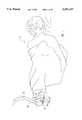
- FIG. 1is a perspective view of an adapter having a rotatable connector and a valve assembly and used for introducing a catheter into the cardiovascular system of a patient;
- FIG. 2is an enlarged perspective view of the adapter in FIG. 1 having the rotatable connector and valve assembly in a partially disassembled condition;
- FIG. 3is an enlarged cross-sectional view of the valve assembly shown in FIG. 2 in a disassembled condition
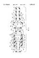
- FIG. 4is a cross-sectional view of the valve assembly shown in FIG. 3 in an assembled condition
- FIG. 5is a cross-sectional view of the valve assembly shown in FIG. 4 and showing a seal positioned therein being compressed so as to seal the valve assembly;
- FIG. 5Ais a cross-sectional view of the valve assembly shown in FIG. 5 with the seal compressing and sealing around a catheter disposed therethrough;
- FIG. 5Bis a cross-sectional view of the valve assembly shown in FIG. 5 without the use of a slip ring positioned adjacent to the seal;
- FIG. 6is an enlarged cross-sectional view of the rotatable connector shown in FIG. 2 in a disassembled condition
- FIG. 7is a cross-sectional view of the rotatable connector shown in FIG. 6 in a first stage of assembly
- FIG. 8is a cross-sectional view of the rotatable connector of FIG. 6 in a second stage of assembly
- FIG. 9is a cross-sectional view of the rotatable connector of FIG. 6 in a fully assembled condition
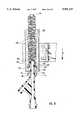
- FIG. 10is a plan view of a positioning apparatus used for attaching a slip ring onto the distal end of the adapter, as shown in FIG. 6;
- FIG. 11is a partial cross-sectional plan view of the positioning apparatus in a first stage for positioning a split ring on the distal end of the adapter;
- FIG. 12is a partial cross-sectional plan view of the positioning apparatus having the split ring positioned proximal of the flange on the distal end of the adapter;
- FIG. 13is an enlarged cross-sectional view of the positioning apparatus compressing the split ring around the distal end of the adapter and proximal to the flange;
- FIG. 14is a cross-sectional view of the positioning apparatus having the split ring securely positioned on the distal end of the adapter.
- a patient 10having an introducer 12 with a distal end (not shown) in fluid communication with the cardiovascular system of patient 10.
- a proximal end 14 of introducer 12projects outside the body of patient 10 and is connected to one embodiment of an adapter 16 incorporating features of the present invention.
- Adapter 16comprises a tubular body 18 having an exterior surface 19 with a distal end 20 and a proximal end 24 positioned at opposing ends thereof.
- a rotatable connector 22is positioned at distal end 20. Rotatable connector 22 is shown in FIG. 1 as providing a fluid coupling between introducer 12 and tubular body 18.
- valve assembly 26Positioned at proximal end 24 is a valve assembly 26.
- valve assembly 26can be used to achieve alternative objectives. In one position, valve assembly 26 can be used to completely block off proximal end 24 of tubular body 18 so as to prevent the escape of blood or other bodily fluids flowing from patient 10, through introducer 12, and into adapter 16.
- valve assembly 26can be used to form a seal around an elongated member 28, such as a catheter or guidewire, when elongated member 28 is received within valve assembly 26 and passed through tubular body 18, introducer 12, and into the cardiovascular system of patient 10. Valve assembly 26 thus also prevents the backflow of bodily fluids from introducer 12 from leaking out of adapter 16 where elongated member 28 is received within valve assembly 26.
- Adapter 16further comprises a supplemental access tube 30 in fluid communication with tubular body 18 between proximal end 24 and distal end 20.
- Supplemental access tube 30is shown in fluid communication with a catheter 32 by way of a connector 34.
- adapter 16can have a plurality of supplemental access tubes communicating with tubular body 18.
- Supplemental access tube 30can be used for introducing fluids or other medical devices into the body of patient 10.
- FIG. 2Depicted in FIG. 2 is a partially exploded or disassembled view of adapter 16.
- access tube 30comprises an exterior surface 39 and an interior surface 36 defining a channel 38 longitudinally extending therethrough.
- Access tube 30is attached in fluid communication at distal end 40 thereof to tubular body 18.
- Opposite distal end 40is a free proximal end 42 having threads 44 positioned thereat. Threads 44 are preferably configured to accommodate a conventional luer lock attachment.
- Access tube 30is preferably positioned at an angle so as to project towards proximal end 24 of tubular body 18.
- a support member 46extends between exterior surface 19 of tubular body 18 and exterior surface 39 of access tube 30. Support member 46 rigidly positions access tube 30 and helps to prevent fracture or breaking of access tube 30.
- Valve assembly 26is depicted in FIG. 2 as further comprising a rotation nut 48, a slip ring 50, and a tubular seal 52.
- FIG. 3discloses a cross-sectional exploded view of valve assembly 26.
- tubular body 18has an interior surface 54 defining a passage 56 longitudinally extending through body 18.
- passage 56is shown as comprising a compression chamber 58 positioned at a proximal terminus 59 of body 18.
- Compression chamber 58has an inner diameter defined by an interior surface 60 extending between a distal end 62 and a proximal end 64.
- Passage 56further comprises a lumen 66 communicating at a proximal end 68 thereof to distal end 62 of compression chamber 58.
- Lumen 66is concentric with compression chamber 58 and has an interior surface 70 having an inner diameter smaller than the inner diameter of compression chamber 58.
- Lumen 66 and compression chamber 58are preferably substantially cylindrical.
- An annular shoulder 72extends between proximal end 68 of lumen 66 and distal end 62 of compression chamber 58.
- An annular first ridge 74proximally projects from annular shoulder 72 and adjacently encircles lumen 66.
- First ridge 74comprises an annular end face 76 and an annular sidewall 78.
- First ridge 74has an outer diameter smaller than the inner diameter of compression chamber 58.
- an annular first receiving groove 80is formed between sidewall 78 of first ridge 74 and interior surface 60 of compression chamber 58.
- exterior surface 19 of tubular body 18includes a substantially cylindrical section 51 surrounding lumen 66 and a substantially rectangular casing 53 surrounding compression chamber 58.
- the configuration of rectangular casing 53is to provide flat surfaces that enable medical personnel to clamp or use other mechanical means for holding adapter 16.
- rectangular casing 53could be fashioned in alternative polygonal or circular cross-sectional configurations.
- first compression lip 55encircling body 18 at proximal end 24 and radially extending outward therefrom is a first compression lip 55.
- First compression lip 55has an outer diameter and will be discussed later in greater detail.
- first engagement threads 57Positioned proximal of first compression lip 55 and also encircling body 18 are first engagement threads 57 which will also be discussed later in greater detail.
- Tubular seal 52is configured to mate within compression chamber 58.
- Tubular seal 52has an exterior surface 82 extending between a proximal end 83 having a proximal end face 84 and a distal end 85 having a distal end face 86.
- Exterior surface 82has an outer diameter approximately equal to the inner diameter of compression chamber 58 such that tubular seal 52 is received within compression chamber 58.
- Seal 52also has an interior surface 88 defining a passageway 90 longitudinally extending therethrough and axially aligned with lumen 66.
- An annular first tongue 92distally projects from distal end face 86 and encircles passageway 90.
- First tongue 92has an annular distal end face 94 and an annular interior sidewall 96.
- Interior sidewall 96defines a first recess 98 concentric with passageway 90 and having an inner diameter greater than the inner diameter of passageway 90.
- FIG. 4which is an assembled view of the elements in FIG. 3
- seal 52is configured such that as seal 52 is mated within compression chamber 58, first tongue 92 is received within first receiving groove 80 and first ridge 74 is received within first recess 98.
- Second tongue 100proximally projects from proximal end face 84 of seal 52 and encircles passageway 90.
- Second tongue 100comprises an annular proximal end the 102 and an annular interior sidewall 104.
- Interior sidewall 104defines a second recess 106 concentric with passage 90 of seal 52 and having an inner diameter greater than the inner diameter of passage 90.
- Slip ring 50is depicted in FIG. 3 as having an interior surface 107 defining an opening 109 longitudinally extending through slip ring 50 and axially aligned with lumen 66.
- Slip ring 50comprises a first ring 108 having an exterior surface 110 with an outer diameter and an interior surface 112 defining a first access 114.
- Proximally attached to first ring 108is an annular second ring 115.
- Second ring 115has an exterior surface 116 with an outer diameter greater than the outer diameter of first ring 108 and an interior surface 118 defining a second access 120.
- Second access 120has an inner diameter greater than the inner diameter of first access 114.
- Second access 120is concentric with first access 114 and communicates therewith to define opening 109.
- slip ring 50is configured such that in an assembled condition first ring 50 is received within second recess 106 of seal 52 while second tongue 100 of seal 52 encircles first ring 108.
- rotation nut 48has a substantially cylindrical configuration and includes a housing 122 with a distal end 124 and an opposing proximal end 126.
- a proximal end wall 128radially extends inward at proximal end 126.
- Housing 122has an exterior surface 127 comprising a first cylindrical portion 129 positioned at distal end 124.
- a plurality of gripping ribs 131radially extend outward on first cylindrical portion 129 and are aligned with the longitudinal access of body 18.
- Exterior surface 127further comprises a second cylindrical portion 133 positioned at proximal end 126 of housing 122 and having an outer diameter greater than the outer diameter of first cylindrical portion 129.
- a plurality of gripping fibs 135also radially outwardly extend on second cylindrical portion 133 and are aligned with longitudinal access of body 18.
- Housing 122also has an interior surface 130 defining a recessed chamber 132 opened at distal end 124.
- An annular second compression lip 137radially, inwardly extends from interior surface 130 and has an inner diameter slightly smaller than the outer diameter of first compression ring 55.
- Second engagement threads 134Positioned proximal of second compression ring 137 on interior surface 130 are second engagement threads 134 configured for rotational, threaded engagement with first engagement threads 57 on proximal end 24 of body 18.
- Rotation nut 48further comprises a tubular shaft 136 distally projecting from proximal end wall 128 within recess chamber 132 of housing 122.
- Shaft 136extends to a distal end 145 having a distal end face 146.
- Shaft 136also has an exterior surface 138 having an outer diameter and an interior surface 140 defining an entryway 142 longitudinally extending through shaft 136 and proximal end wall 128.
- Interior surface 140radially outwardly expands at proximal end 126 of housing 122 to form an enlarged receiving mouth 144.
- An annular second ridge 148distally projects from distal end face 146 of shaft 136 and encircles entryway 142 extending through shaft 136.
- Second ridge 148is defined by an annular distal end face 150 and an annular outer sidewall 152.
- Outer sidewall 152has an outer diameter smaller than the inner diameter of compression chamber 58. Accordingly, a second receiving groove 149 is formed between outside wall 152 of second ridge 148 and interior surface 60 of compression chamber 58 when shaft 136 is received within compression chamber 58.
- rotation nut 48is configured so that shaft 136 can be received within compression chamber 58 while, simultaneously, proximal end 24 of body 18 is received within recess chamber 132 of rotation nut 48.
- first compression lip 55having an outer diameter slightly larger than the inner diameter of second compression lip 137 becomes biased against second compression lip 137.
- second compression lip 137 and distal end 124radially outwardly expand to allow first compression lip 55 to pass through second compression lip 137. Once this is accomplished, second compression lip 137 returns to its original configuration behind first compression lip 55, thereby holding proximal end 24 of body 18 within recess 132 of rotation nut 48.
- first engagement threads 57 on proximal end 24 of body 18are biased against second engagement threads 134 positioned on interior surface 130 of housing 122.
- First engagement threadsare configured to complimentarily engage second engagement threads 134 when rotation nut 48 is rotated relative to body 18. The rotational engagement between first engagement threads 57 and second engagement threads 134 causes shaft 136 to advance within compression chamber 58.
- distal end 145 of shaft 136is mated with second ring 115 of slip ring 50. More specifically, annular second ridge 148 at distal end 145 of shaft 136 is received within second access 120 of slip ring 50 and second ring 115 of slip ring 50 is received within second receiving groove 149 of shaft 136.
- lumen 66 in body 18, passageway 90 in seal 52, opening 109 in slip ring 50, and entryway 142 in shaft 136are each axially aligned and communicating with each other to allow passage 56 to extend therethrough.
- an elongated member 28such as a catheter or guidewire, can be longitudinally disposed through passage 56 for insertion within the cardiovascular system of a patient, as discussed with regard to FIG. 1.
- shaft 136can be selectively advanced within compression chamber 58 until interior surface 88 of seal 52 constricts to press and seal around an exterior surface 29 of elongated member 28.
- the amount of pressure applied by seal 52 on elongated member 28can be selectively controlled.
- elongated member 28can be advanced or retracted within passage 56 while maintaining a seal around elongated member 28 that prevents leakage of blood or other fluids back flowing through lumen 66.
- Seal 52is preferably made from a deformable, resilient material which allows seal 52 to compress and either independently seal or seal around a member positioned therethrough. The material should also enable seal 52 to independently conform back to its original configuration as shaft 136 is retracted from compression chamber 58.
- the preferred material for seal 52is silicone however, other kinds of conventional rubbers can also be used.
- slip ring 50The function of slip ring 50 is to prevent the twisting of seal 52 as shaft 136 is advanced within compression chamber 58. That is, as shaft 136 is advanced during annular rotation, distal end thee 146 of shaft 136 slips against slip ring 50, thereby preventing transfer of this annular rotation to seal 52 which could twist seal 52. Twisting of seal 52 can cause seal 52 to apply a counter rotating force to shaft 136 which, if sufficient, can independently back-off or unscrew shaft 136 from within compression chamber 58, thereby opening seal 52 and possibly causing fluid leakage thereat.
- slip ring 50is preferably made from a relatively rigid material having a relatively low coefficient of friction such as polytetrafluoroethylene, more commonly known as Teflon®.
- a small quantity of oil or other lubricantsuch as a medical grade silicone oil, can be used to lubricate the interactive components of valve assembly 26.
- Seal 52, and more specifically interior surface 88 of seal 52is also preferably coated with an oil. The oil helps prevent interior surface 88 of seal 52 from sticking together as shaft 136 is retracted from within compression chamber 58 to open passageway 90 through seal 52.
- valve assembly 26can be configured without the use of slip ring 50.
- annular second ridge 148 on shaft 136is received within second recess 106 of seal 52 while simultaneously annular second tongue 100 is received within second receiving groove 149 on shaft 136.
- shaft 136 and seal 52have a relationship which permits shaft 136 to advance under rotation without twisting or rotating seal 52. This can be accomplished by either the addition of lubricants or by forming seal 52 out of a material having a relatively low coefficient of friction.
- body 18 and rotation nut 48are preferably molded from a clear polycarbonate plastic. Such a material allows for easy molding, moderate flexibility, and visualizing of the internal components and operation of adapter 16. Of course, alternative types of conventional plastics can also be used.
- meansare provided for coupling shaft 136 to body 18 and for selectively advancing shaft 136 into compression chamber 58 so as to compress and deform seal 52 within compression chamber 58.
- the means for coupling and advancingincludes first engagement threads 57 positioned on exterior surface 19 at proximal end 24 of body 18 and second engagement threads 134 positioned on interior surface 130 of housing 122.
- first engagement threads 57positioned on exterior surface 19 at proximal end 24 of body 18
- second engagement threads 134positioned on interior surface 130 of housing 122.
- rotational engagement between first engagement threads 57 and second engagement threads 134couples shaft 136 to body 18.
- rotation of shaft 136 relative to body 18causes shaft 136 to advance within compression chamber 58 to compress and deform seal 52 within compression chamber 58.
- first engagement threads 57could be positioned on interior surface 60 of compression chamber 58 while second engagement threads 134 are complimentarily positioned on exterior surface 138 of shaft 136 for coupling and advancing shaft 136 within compression chamber 58.
- complementary sets of barbs or ridgescould replace first engagement threads 57 and second engagement threads 134. As shaft 136 is advanced within compression chamber 58, the complementary sets of barbs or ridges can mechanically interact to couple shaft 136 to body 18.
- the present inventionalso provides means for interlocking distal end 85 of seal 52 with annular shoulder 72 of body 18.
- the interlockingis used to prevent seal 52 from becoming displaced or misoriented within compression chamber 58. More specifically, the interlocking is used to prevent seal 52 from sticking within lumen 66 after seal 52 is compressed within compression chamber 58.
- the above means for interlocking distal end 85 of seal 52comprises annular first ridge 74 projecting from shoulder 72 of body 18 to form first receiving groove 80 positioned between first ridge 74 and interior surface 62 of compression chamber 58.
- the above interlocking meansalso comprises annular first tongue 92 distally projecting from distal end face 86 of seal 52 and defining first recess 98.
- first tongue 92is received within first receiving groove 80 and annular first ridge 74 is received within first recess 98.
- distal end 85 of seal 52is interlocked with shoulder 72 since, during compression of seal 52, first tongue 92 is held within first receiving groove 80 and prevented by first ridge 74 from slipping or flowing into lumen 66.
- Use of this interlocking configurationsignificantly prevents seal 52 from sticking within lumen 66 after seal 52 has been compressed within compression chamber 58.
- first tongue 92could comprise one or more individual fingers distally projecting from proximal end face 86 of seal 52.
- annular first receiving groove 80could be configured to correspond to one or more individual receiving slots for receiving the individual fingers.
- the present inventionalso provides means for interlocking proximal end 83 of seal 52 with distal end 145 of shaft 136.
- the interlockingis used to prevent displacement or misalignment of seal 52 within compression chamber 58. More specifically, the interlocking is used to prevent seal 52 from sticking within entryway 142 of shaft 136 after seal 52 is compressed within compression chamber 58.
- the means for interlocking proximal end 83 of seal 52includes annular second tongue 100 proximally projecting from proximal end face 84 of seal 52 and defining second recess 106.
- the interlocking meansfurther includes annular second ridge 148 distally projecting from distal end face 146 of shaft 136 and defining second receiving groove 149.
- second ridge 148can be received within second recess 106 and annular second tongue 100 can be received within second receiving groove 149.
- proximal end 83 of seal 52is interlocked with distal end 145 of shaft 136 since, during compression of seal 52, second tongue 100 is held within second receiving groove 149 and prevented by second ridge 148 from slipping or flowing into entryway 142.
- the means for interlocking proximal end 83 of seal 52can likewise have the same alternative configurations as discussed with the means for interlocking distal end 85 of seal 52.
- second tongue 100can comprise one or more individual fingers proximally projecting from proximal end face 84 of seal 52.
- the means for interlocking proximal end 83 of seal 52can include slip ring 50 being positioned between seal 52 and shaft 136 as discussed with regard to FIGS. 4 and 5.
- second ridge 148is received within second access 120 of slip ring 50 and first ring 108 of slip ring 50 is received within second recess 106 of seal 52, thereby interlocking proximal end 83 of seal 52 with distal end 145 of shaft 136 through slip ring 50.
- This configurationalso prevents second tongue 100 from entering within entryway 142 which could result in seal 52 sticking within entryway 142 of shaft 136 after compression of seal 52 within compression chamber 58.
- the present inventionalso provides means for selectively closing lumen 66 at proximal end 24 of tubular body 18.
- the means for selectively closingincludes valve assembly 26, as discussed above, and includes all of the related alternative embodiments as also discussed above.
- rotatable connector 22 positioned at distal end 20 of body 18is shown in a partial disassembled configuration.
- rotatable connector 22comprises a retaining flange 158 encircling and radially extending outward from proximal end 20 of body 18.
- Rotatable connector 22also includes an annular cap 160 rotatably encircling body 18 proximal of flange 158 and a split ring 162 rotatably encircling body 18 between flange 158 and cap 160.
- Rotatable connector 22further comprises a tubular hub 164.
- FIG. 6discloses a cross-sectional fully exploded view of rotatable connector 22.
- retaining flange 158comprises an annular proximal flange 166 encircling and radially extending outward on distal end 20 of body 18.
- Proximal flange 166comprises an annular proximal side wall 168, an annular distal side wall 170, and an annular outer surface 172.
- Retaining flange 158further comprises an annular distal flange 174 encircling and radially extending outward from said distal end 20 of body 18.
- Distal flange 174is shown as having an annular proximal side wall 176, an annular distal side wall 178, and an annular outer surface 180.
- a cylindrical section 175Positioned between proximal flange 166 and distal flange 174 is a cylindrical section 175 having a reduced outer diameter.
- retaining flange 158can be made having a uniform outer diameter along its length.
- Distally projecting from distal sidewall 178 of distal flange 158is an annular ridge 182 encircling body 18.
- Also distally projecting from distal sidewall 178 of distal flange 174is a cylindrical stem 184 adjacently encircling passage 56 extending through body 18.
- Stem 18has an exterior surface 186 and terminates at a distal terminus 188.
- Annular cap 160is shown in FIG. 6 as comprising an annular sleeve 190 having a proximal end 192 and an opposing distal end 194.
- Sleeve 190also has an interior surface 196 having an inner diameter and defining a recess 198.
- An annular end wall 200radially extends inward from interior surface 196 of sleeve 190 at a proximal end 192 thereof to define an aperture 202.
- Aperture 202has an inner diameter greater than the outer diameter of both proximal flange 166 and distal flange 174. Accordingly, as shown in FIG. 7, distal end 20 of body 18 can be received within aperture 202 of cap 160 so that cap 160 can rotatably encircle body 18 proximal of retaining flange 158.
- split ring 162is shown as comprising an annular proximal end face 204, an annular distal face 206, and an annular outer surface 208 having an outer diameter.
- Split ring 162further comprises an interior surface 210 defining an opening 212 having an inner diameter and longitudinally extending therethrough.
- Split ring 162is further shown as having a first end 214 adjacent to a second end 216 which define a slit 218. Slit 218 extends between distal end face 206 and proximal end face 204 of split ring 162. Opening 212 through split ring 162 has an inner diameter smaller than the outer diameter of proximal flange 166.
- split ring 162is capable of radially expanding to enable distal end 20 of body 18 to be received within opening 212 so that split ring 162 can rotatably encircle body 18 between proximal flange 166 and cap 160, as shown in FIG. 7.
- reference to the "outer diameter" of split ring 162 and the “inner diameter” of opening 212 through split ring 162refer to dimensions of split ring 162 in an unexpanded condition. Of course, such dimensions increase as split ring 218 expands as a result of the separation of first end 214 and second end 216.
- Tubular hub 164is disclosed in FIG. 6 as having a proximal end 220, a distal end 222, and an exterior surface 224 with an outer diameter extending therebetween.
- Hub 164further includes an interior surface 226 defining a passageway 228 longitudinally extending therethrough.
- Passageway 228is shown in FIG. 6 as comprising an access chamber 230 positioned at proximal end 220 of hub 164.
- Access chamber 230is defined by an interior surface 232 extending from a proximal end 234 to a distal end 236 of access chamber 230.
- Access chamber 230is further defined as comprising a transition bore 238, an entrance bore 240, and a sealing bore 242.
- Transition bore 238is defined by cylindrical interior surface 239 that extends between a proximal end 244 and a distal end 246.
- Entrance bore 242has an inner diameter greater than the inner diameter of transition bore 238 and is defined by cylindrical interior surface 243 that extends from a proximal terminus 241 of hub 164 to proximal end 244 of transition bore 238.
- An annular shoulder 248extends between proximal end 244 of transition bore 238 and entrance bore 240.
- Sealing bore 242has an inner diameter smaller than the inner diameter of transition bore 238 and is defined by cylindrical interior surface 245 that extends from distal end 246 of transition bore 238 to distal end 236 of access chamber 230.
- passageway 228also includes a transfer duct 250 having a proximal end 252 concentric with distal end 236 of access chamber 230.
- Transfer duct 250is defined by an interior surface 254 having an inner diameter smaller than the inner diameter of access chamber 230.
- a shoulder 256extends between proximal end 252 of transition duct 250 and distal end 236 of access chamber 230.
- Distal end 222 of hub 164is also shown as having an interior surface 258 defining a receiving slot 260 and having a set of engagement threads 262 positioned thereon.
- Engagement threads 262are preferably configured for a conventional luer lock attachment. However, alternative types of threads can also be used.
- Distally projecting from shoulder 256 within hub 164is a tubular stem 264 having interior surface 254 with transfer duct 250 extending therethrough as previously discussed.
- a seal ring 266is shown in FIG. 6 for positioning within receiving slot 260 proximal of engagement threads 262. As shown in FIG. 7, seal ring 266 can then be used for sealing a corresponding connector (not shown) threadedly engaged with engagement threads 262.
- FIG. 6also discloses a seal ring 268 having an exterior surface 269 configured to be biased against shoulder 248 and encircling transfer duct 250.
- shoulder 248includes an annular mouth 270 encircling transfer duct 250 and positioned adjacent thereto.
- Shoulder 248further includes a grooved face 272 positioned between annual mouth 270 and interior surface 232 of access chamber 230. Grooved face 272 has a configuration complimentary to exterior surface 269 of seal ring 268 so as to produce a complementary fit therebetween as shown in FIG. 7.
- assembly of rotatable connector 22is a multi-step process.
- split ring 162 and cap 160are positioned to rotatably encircle body 18 proximal of retaining flange 158 as previously discussed.
- seal ring 268is positioned within access chamber 230 so as to be biased against grooved face 272 of shoulder 248. In this position, distal end 20 of body 18 is advanced within access chamber 230, until distal sidewall 178 of distal flange 174 is biased against seal ring 268.
- distal end 20 of body 18is preferably configured to mate with access chamber 230 so as to produce an airless seal between transfer duct 250 in hub 164 and passage 56 in body 18.
- distal flange 174is sized to snugly be received within sealing bore 242 and distal stem 184 is sized to snugly be received within seal 268.
- seal ring 268deforms to fill all surrounding space and in so doing presses the air therefrom.
- distal terminus 188 of distal stem 184is biased against annular mouth 270 of shoulder 248, thereby completely bounding seal ring 268 in a substantially airless enclosure.
- FIG. 8also discloses split ring 162 being received within entrance bore 240 so that distal end face 206 of split ring 162 is biased against proximal sidewall 168 of proximal flange 166. This configuration urges distal sidewall 178 of distal flange 174 against seal ring 268, thereby maintaining the airless seal discussed above.
- cap 160has an inner diameter larger than the outer diameter of hub 164. Accordingly, as cap 160 and hub 164 are pressed together, proximal end 220 of hub 164 is received within recess 198 of cap 160. Furthermore, split ring 162 is shown positioned so as to have an exposed portion 271 proximally projecting from entrance bore 240 of hub 164 and a gap 275 positioned between end face 206 of split ring 162 and shoulder 248 of hub 164. Accordingly, as cap 160 and hub 164 are pressed together, end well 200 of cap 160 produces a positive compression force against split ring 162. In turn, split ring 162 produces a positive compression force against proximal flange 166 as discussed above. In this configuration, as shown in FIG. 9, an adhesive 273 is applied between the interior surface 196 of cap 160 and exterior surface 220 of hub 164 so as to rigidly secure cap 160 to hub 164.
- the preferred adhesive for connecting cap 160 to hub 164is a conventional ultraviolet adhesive. After hub 164 is received within recess 198 of cap 160, a small amount of adhesive 273 is positioned at distal end 194 of cap 160 at the intersection of cap 160 and hub 164. Adhesive 273 then wicks around hub 164 and between interior surface 196 of cap 160 and exterior surface 224 of hub 164. Ultraviolet light is then directed onto rotatable connector 22 which then immediately sets adhesive 273. Of course, alternative types of adhesives can also be used. Once cap 160 is secured in place, split ring 162 is continually urged against proximal flange 168 so as to maintain the airless seal between passage 56 of body 18 and transfer duct 250 of hub 164. Furthermore, the attachment of cap 160 to hub 164 prevents separation of body 18 and hub 164 but allows both hub 164 and cap 160 to annularly rotate relative to body 18.
- split ring 162 and seal ring 268typically rotate with hub 164.
- Slip surfacesare thus formed between distal end face 206 of split ring 162 and proximal sidewall 168 of proximal flange 166 and between distal sidewall 178 of distal flange 174 and seal ring 268.
- the ease at which hub 164 rotates relative to body 18can thus be varied by the material used for split ring 167 and seal ring 268.
- Split ring 162is preferably made from a material having a low coefficient of friction such as polytetrafluoroethylene so as to allow easy and smooth rotation of hub 164 relative to body 18.
- Split ring 162can alternatively be made of materials having different coefficients of friction such as acetal plastic.
- Seal ring 268is preferably made from silicone.
- seal ring 268can be made of other materials having varied coefficients of friction.
- seal ring 268can be made from natural rubber, ethylene propylene, and fluorosilicone.
- hub 164rotates relative to body 18 is also a function of the amount of force used in applying cap 160 onto hub 164. That is, by increasing the force in pressing cap 160 and hub 164 together, the friction between the above discussed slip surfaces is also increased, thereby making it more difficult to rotate 164 relative to body 18.
- the present inventionalso provides means for connecting distal end 20 of tubular body 18 to a medical device, such as introducer 12, used in fluid communication with the body of patient 10.
- a medical devicesuch as introducer 12
- the means for connectingcomprises rotatable connector 22, as disclosed above, and includes all of the alternative embodiments as discussed therewith.
- Positioning apparatus 274includes a rigid, substantially cylindrical shaft 276 having a top end 278 and a bottom end 280. Shall 276 is shown as comprising a retaining shaft 282 positioned at top end 278 and having an outer diameter smaller than the inner diameter of split ring 162. An expansion shaft 284 is positioned at bottom end 280 and has an outer diameter larger than the inner diameter of split ring 162. Finally, a frustoconical transition shaft 286 extends between retaining shaft 282 and expansion shaft 280.
- Positioning apparatus 274further comprises a housing 288 having an exterior surface 290 extending between a top end 292 and a bottom end 294. Positioned at top end 292 is a top end face 293 and positioned at bottom end 294 is a bottom end face 295. Housing 288 further includes an interior surface 296 defining a passageway 298 extending therethrough. Interior surface 296 defines a plurality of differently configured sections. Positioned at top end 292 of housing 288 is a cylindrical first surface 306 having an inner diameter substantially equal to the outer diameter of split ring 162 and extending between a first end 297 and a second end 299. Near top end 292, first surface 306 gradually radially expands outward so as to form an enlarged receiving mouth 308 at top end face 293.
- a cylindrical second surface 302is aligned with and positioned adjacent to second end 299 of first surface 306.
- Second surface 302has an inner diameter larger than the inner diameter of first surface 306.
- Extending between first surface 306 at second end 299 and second surface 302is an annular shoulder 305.
- a cylindrical third surface 300is positioned at bottom end 294 of housing 288.
- Third surface 300has an inner diameter substantially equal to the outer diameter of split ring 162.
- a frustoconical constriction surface 304extends between second surface 302 and third surface 300.
- split ring 162To attach split ring 162 onto body 18, initially bottom end 280 of shaft 276 is received within cylindrical first surface 306 and top end 278 of shaft 276 is received within opening 212 of a plurality of split rings 162. The split rings 162 thus encircle shaft 276 as shown in FIG. 10.
- the present inventionprovides means for urging split ring 162 received on retaining shaft 282 against transition shaft 286 of shall 276.
- a weight 307is provided having an interior surface 308 defining a channel 310 longitudinally extending therethrough.
- Channel 310has an inside diameter larger than the outer diameter of retaining shaft 282 but smaller than the outer diameter of split ring 162.
- Top end 271 of retaining shaft 282is received within channel 310 so that weight 307 encircles retaining shaft 282.
- Weight 307provides a gravitational force that pushes split rings 162 down the length of retaining shaft 282 and towards transition shaft 286.
- Split rings 162are held in place by the fact that a split ring 322 at bottom end 280 is unable to expand over transition shaft 286 because interior surface 296 of cylindrical first surface 306 is comparable to the outside diameter of split rings 322.
- Weight 307also has an outer diameter which can either be larger than or smaller than the inner diameter of first surface 306. Of course, other types of mechanical or manual forces could be applied to split rings 162 to push split rings 162 toward transition shaft 286.
- Meansare also provided for moving housing 290 relative to shaft 276. Preferably, this is accomplished between a first position and a second position.
- housing 288is shown having a plurality of threads 312 positioned on exterior surface 290.
- a clamp 314 having complementary threads 316mechanically engages housing 288 by thread connection between threads 312 on housing 288 and threads 316 on clamp 314.
- Clamp 314can then be attached to a piston or any other kind of mechanical or manual device which permits housing 288 to move along a longitudinal access of shaft 276.
- shaft 276is held stationary by being clamped at top end 278.
- expansion shaft 284also includes an interior surface 318 defining a recess 320.
- Recess 320is opened at bottom end face 324 of expansion shaft 284 and is configured to receive retaining flange 158 positioned on distal end 20 of body 18.
- Interior surface 318is shown as comprising a substantially cylindrical first portion 326 positioned at bottom end face 324 of expansion shaft 284.
- a substantially cylindrical second portion 328is axially aligned with first portion 326 and extends towards top end 278 of shaft 276.
- First portion 326has an inner diameter larger than the outer diameter of retaining flange 158.
- Second portion 328has an inner diameter smaller than the outer diameter of retaining flange 158. Accordingly, as distal end 20 of tubular body 18 is advanced within recess 320, distal flange 174 of retaining flange 158 becomes biased against an annular shoulder 330 extending between first portion 326 and second portion 328.
- housing 288With distal end 20 of body 18 disposed within recess 320, housing 288 begins moving in the direction of arrow A as shown in FIG. 11. At the stage shown in FIG. 11, a sufficient portion of transition shaft 286 of shaft 276 is extending out of cylindrical first surface 306 of housing 288 to cause first split ring 322, under the force of weight 307, to press out of cylindrical first surface 306 and expand over transition shaft 286 into cylindrical second surface 302 of housing 288.
- split ring 322is positioned within cylindrical second surface 302, housing 288 begins moving in the direction of arrow B as shown in FIG. 12. By so doing, first split ring 322 is engaged by shoulder 305 so as to expand and pass over expansion shaft 284. After first split ring 322 completely passes over expansion shaft 284 so as to encircle body 18 proximal of retaining flange 158, split ring 322 partially self-constricts around body 18 so as to be aligned with bottom end face 324 of expansion shaft 284.
- housing 288then begins to travel in the direction of arrow A. As housing 288 does so, bottom end face 324, mad at times proximal flange 166, holds split ring 322 in position while constriction surface 304 and third surface 300 of housing 288 radially inwardly compress first split ring 322 so as to snugly fit around body 18 as shown in FIG. 14. Distal end 20 of body 18 having first split ring 322 encircling body 18 proximal of retaining flange 158 can then be removed from recess 320 for subsequent attachment of a different split ring to a different body.
- cylindrical third surface 300, cylindrical second surface 302, and constriction surface 304can be removed from passage 298. Accordingly, in this embodiment passageway 298 exclusively defines cylindrical first surface 306 extending from top end 292 to bottom end 294 of housing 288. During operation, bottom end face 295, as shown in FIG. 11, acts like shoulder 305 to position split ring 322 around body 18 as discussed above. In this embodiment, however, split ring 322 is not subsequently compressed around body 18 by housing 288. Of course, alternative embodiments can be used to compress split ring 322 around body 18.
Landscapes
- Health & Medical Sciences (AREA)
- Heart & Thoracic Surgery (AREA)
- Pulmonology (AREA)
- Engineering & Computer Science (AREA)
- Anesthesiology (AREA)
- Biomedical Technology (AREA)
- Hematology (AREA)
- Life Sciences & Earth Sciences (AREA)
- Animal Behavior & Ethology (AREA)
- General Health & Medical Sciences (AREA)
- Public Health (AREA)
- Veterinary Medicine (AREA)
- Infusion, Injection, And Reservoir Apparatuses (AREA)
Abstract
Description
Claims (30)
Priority Applications (1)
| Application Number | Priority Date | Filing Date | Title |
|---|---|---|---|
| US08/502,753US5591137A (en) | 1995-07-14 | 1995-07-14 | Hemostasis valve with locking seal |
Applications Claiming Priority (1)
| Application Number | Priority Date | Filing Date | Title |
|---|---|---|---|
| US08/502,753US5591137A (en) | 1995-07-14 | 1995-07-14 | Hemostasis valve with locking seal |
Publications (1)
| Publication Number | Publication Date |
|---|---|
| US5591137Atrue US5591137A (en) | 1997-01-07 |
Family
ID=23999262
Family Applications (1)
| Application Number | Title | Priority Date | Filing Date |
|---|---|---|---|
| US08/502,753Expired - LifetimeUS5591137A (en) | 1995-07-14 | 1995-07-14 | Hemostasis valve with locking seal |
Country Status (1)
| Country | Link |
|---|---|
| US (1) | US5591137A (en) |
Cited By (126)
| Publication number | Priority date | Publication date | Assignee | Title |
|---|---|---|---|---|
| WO1999019008A1 (en) | 1997-10-14 | 1999-04-22 | Merit Medical Systems, Inc. | Pulse fluid infusion systems |
| US5911710A (en)* | 1997-05-02 | 1999-06-15 | Schneider/Namic | Medical insertion device with hemostatic valve |
| US5921968A (en)* | 1997-11-25 | 1999-07-13 | Merit Medical Systems, Inc. | Valve apparatus with adjustable quick-release mechanism |
| US5935112A (en)* | 1997-10-15 | 1999-08-10 | Stevens; Brian W. | Hemostasis valve with catheter/guidewire seals |
| US5992899A (en)* | 1997-09-17 | 1999-11-30 | Becton, Dickinson And Company | Adapter for mounting a fluid handling device on a catheter tubing |
| US6059759A (en)* | 1997-10-14 | 2000-05-09 | Merit Medical Systems, Inc. | Infusion catheter systems with tactile sensing feedback |
| WO2000048663A1 (en)* | 1999-02-17 | 2000-08-24 | Becton, Dickinson And Company | Needleless injection site and guidewire assembly |
| US6287280B1 (en) | 1999-09-07 | 2001-09-11 | Merit Medical Systems, Inc. | Hemostasis valve apparatus with integral introducer |
| US6331176B1 (en)* | 1999-03-11 | 2001-12-18 | Advanced Cardiovascular Systems, Inc. | Bleed back control assembly and method |
| US6572590B1 (en) | 2000-07-13 | 2003-06-03 | Merit Medical Systems, Inc. | Adjustable quick-release valve with toggle capability |
| US20030216771A1 (en)* | 2002-03-15 | 2003-11-20 | Thomas P. Osypka | Locking vascular introducer assembly with adjustable hemostatic seal |
| EP1374926A1 (en)* | 2002-06-28 | 2004-01-02 | Bioservice S.p.A. | Self-sealing valve for medical use |
| US6723073B2 (en) | 2002-09-06 | 2004-04-20 | Cardiac Pacemakers, Inc. | Hemostasis valve for use with a left ventricular pacing lead |
| US20040087986A1 (en)* | 2002-06-24 | 2004-05-06 | Berlin Heart Ag | Device for connecting a cannula made of a flexible material with a tube |
| US20040147877A1 (en)* | 2003-01-27 | 2004-07-29 | Heuser Richard R | Catheter introducer system |
| US20040172008A1 (en)* | 2002-11-19 | 2004-09-02 | Gmp/Cardiac Care, Inc. | Hemostasis valve and method of using a hemostasis valve |
| US20050085789A1 (en)* | 2003-08-26 | 2005-04-21 | Khan Mazhar M. | Haemostasis device |
| US20050119637A1 (en)* | 2002-04-08 | 2005-06-02 | Dan Lundgren | Transcutaneous portal device |
| US20050197635A1 (en)* | 2003-11-13 | 2005-09-08 | Greydanus Dominique J. | One stage saline lock and intravenous catheter set and method of use |
| US20060047222A1 (en)* | 2003-08-27 | 2006-03-02 | Heuser Richard R | Catheter guidewire system using concentric wires |
| US20070010796A1 (en)* | 2005-06-23 | 2007-01-11 | Derek Moran | Catheter device |
| US20070017583A1 (en)* | 2005-07-06 | 2007-01-25 | Fangrow Thomas F Jr | Medical connector with closeable male luer |
| US20070073271A1 (en)* | 2003-11-15 | 2007-03-29 | Brucker Gregory G | Catheter for diagnostic imaging and therapeutic procedures |
| US20070120083A1 (en)* | 2003-12-30 | 2007-05-31 | Vasogen Ireland Limited | Valve assembly |
| US20070185567A1 (en)* | 2006-01-25 | 2007-08-09 | Heuser Richard R | Catheter system with stent device for connecting adjacent blood vessels |
| US20070265563A1 (en)* | 2006-05-11 | 2007-11-15 | Heuser Richard R | Device for treating chronic total occlusion |
| US7300459B2 (en) | 2002-10-17 | 2007-11-27 | Heuser Richard R | Stent with covering and differential dilation |
| US20070276434A1 (en)* | 2004-01-23 | 2007-11-29 | Js Vascular, Inc. | Vascular sheath |
| US20070292193A1 (en)* | 2004-05-13 | 2007-12-20 | Bao Sheng Corporation | Enhanced fluid dispenser container fitment |
| JP2008005974A (en)* | 2006-06-28 | 2008-01-17 | Nippon Sherwood Medical Industries Ltd | Luer fixed fitting connection structure |
| US20080097339A1 (en)* | 2006-08-31 | 2008-04-24 | Medrad, Inc. | Catheter with filtering and sensing elements |
| US7374567B2 (en) | 2006-01-25 | 2008-05-20 | Heuser Richard R | Catheter system for connecting adjacent blood vessels |
| US20080275397A1 (en)* | 2004-08-31 | 2008-11-06 | Bonnette Michael J | Low pierce force needle port |
| US20080287920A1 (en)* | 2007-05-16 | 2008-11-20 | Fangrow Thomas F | Medical connector with closeable male luer |
| US20080294113A1 (en)* | 2007-05-22 | 2008-11-27 | Oivind Brockmeier | Access Assembly With Ribbed Seal |
| US20080306469A1 (en)* | 2007-06-05 | 2008-12-11 | Takuya Masuda | Medical connector |
| US20080312662A1 (en)* | 2007-06-13 | 2008-12-18 | Hickingbotham Dyson W | Self Sealing Cannula / Aperture Closure Cannula |
| US20090012429A1 (en)* | 2004-08-25 | 2009-01-08 | Heuser Richard R | Catheter guidewire system using concentric wires |
| US20090012476A1 (en)* | 2007-07-05 | 2009-01-08 | Galt Medical Corporation | Hemostasis valve for a catheter introducer |
| US20090125045A1 (en)* | 2004-08-25 | 2009-05-14 | Heuser Richard R | Systems and methods for ablation of occlusions within blood vessels |
| WO2009105227A1 (en)* | 2008-02-19 | 2009-08-27 | Bipore Medical Devices, Inc. | Sealing arrangement for medical introducer |
| US20090259200A1 (en)* | 2008-04-14 | 2009-10-15 | Merit Medical Systems, Inc. | Quick release hemostasis valve |
| US7749198B2 (en) | 2007-05-22 | 2010-07-06 | Tyco Healthcare Group Lp | Surgical portal apparatus with variable adjustment |
| US20100174242A1 (en)* | 2008-12-19 | 2010-07-08 | Harold Anderson | Medical connector with closeable luer connector |
| US20110004062A1 (en)* | 2008-03-24 | 2011-01-06 | Hideaki Asai | Anti-leak valve unit for overtube |
| US20110028942A1 (en)* | 2008-04-01 | 2011-02-03 | Hideya Saitoh | Catheter connector |
| US20110054261A1 (en)* | 2009-08-31 | 2011-03-03 | Tyco Healthcare Group Lp | Surgical portal apparatus including gear and lockout assembly |
| US20110077680A1 (en)* | 2008-01-28 | 2011-03-31 | Heuser Richard R | Large mouth snare device |
| US20110112375A1 (en)* | 2009-11-12 | 2011-05-12 | Tyco Healthcare Group Lp | Portal apparatus including conformable cup seal |
| US20110152774A1 (en)* | 2009-12-23 | 2011-06-23 | Jose Luis Lopez | Ophthalmic valved trocar cannula |
| US20110152775A1 (en)* | 2009-12-23 | 2011-06-23 | Jose Luis Lopez | Ophthalmic valved trocar vent |
| US20110197900A1 (en)* | 2007-03-20 | 2011-08-18 | Heuser Richard R | Percutaneous interventional cardiology system for treating valvular disease |
| US8062321B2 (en) | 2006-01-25 | 2011-11-22 | Pq Bypass, Inc. | Catheter system for connecting adjacent blood vessels |
| US20120253118A1 (en)* | 2007-09-27 | 2012-10-04 | Raphael Meloul | Bronchoscope Adapter And Method |
| US8486024B2 (en) | 2011-04-27 | 2013-07-16 | Covidien Lp | Safety IV catheter assemblies |
| US20130237753A1 (en)* | 2009-11-06 | 2013-09-12 | Nico Corporation | Surgical interface for use with endoscope |
| US8628497B2 (en) | 2011-09-26 | 2014-01-14 | Covidien Lp | Safety catheter |
| US8647310B2 (en) | 2010-05-06 | 2014-02-11 | Icu Medical, Inc. | Medical connector with closeable luer connector |
| US8715250B2 (en) | 2011-09-26 | 2014-05-06 | Covidien Lp | Safety catheter and needle assembly |
| EP2548605A4 (en)* | 2010-03-15 | 2014-05-28 | Terumo Corp | INTRODUCTORY SET |
| US20140187866A1 (en)* | 2010-09-17 | 2014-07-03 | United States Endoscopy Group, Inc. | Biopsy inlet valve |
| WO2014107593A1 (en)* | 2013-01-04 | 2014-07-10 | Heartware, Inc. | Access port |
| US8834422B2 (en) | 2011-10-14 | 2014-09-16 | Covidien Lp | Vascular access assembly and safety device |
| US8939938B2 (en) | 2006-10-12 | 2015-01-27 | Covidien Lp | Needle tip protector |
| US20150157810A1 (en)* | 2013-12-06 | 2015-06-11 | Genentech, Inc. | Apparatus and methods for low-volume medicament delivery |
| US9168366B2 (en) | 2008-12-19 | 2015-10-27 | Icu Medical, Inc. | Medical connector with closeable luer connector |
| EP2802374A4 (en)* | 2012-01-09 | 2016-02-24 | Bio2 Medical Inc | CATHETER CONNECTOR BASE APPARATUS AND METHODS OF USE |
| EP3088039A1 (en)* | 2015-04-23 | 2016-11-02 | Freudenberg Medical, LLC | An automatic medical valve with a variable diameter seal |
| US9933094B2 (en) | 2011-09-09 | 2018-04-03 | Icu Medical, Inc. | Medical connectors with fluid-resistant mating interfaces |
| WO2018071750A1 (en) | 2016-10-13 | 2018-04-19 | Covellus Llc | Modular medical device catheter system |
| WO2018169664A1 (en)* | 2017-03-13 | 2018-09-20 | Boston Scientific Limited | Hemostasis valves and methods for making and using hemostasis valves |
| US10123814B2 (en) | 2016-04-15 | 2018-11-13 | Temple University—Of the Commonwealth System of Higher Education | Infusion catheter and method of use |
| US10335186B2 (en) | 2012-11-20 | 2019-07-02 | Inari Medical, Inc. | Methods and apparatus for treating embolism |
| US10342571B2 (en) | 2015-10-23 | 2019-07-09 | Inari Medical, Inc. | Intravascular treatment of vascular occlusion and associated devices, systems, and methods |
| US10349960B2 (en) | 2014-06-09 | 2019-07-16 | Inari Medical, Inc. | Retraction and aspiration device for treating embolism and associated systems and methods |
| US20190224450A1 (en)* | 2018-01-19 | 2019-07-25 | St. Jude Medical, Cardiology Division, Inc. | Locking guide catheter hubs |
| US10524811B2 (en) | 2015-10-23 | 2020-01-07 | Inari Medical, Inc. | Intravascular treatment of vascular occlusion and associated devices, systems, and methods |
| US10557552B2 (en) | 2016-11-21 | 2020-02-11 | Cardiac Pacemakers, Inc. | Trough seal |
| US10695550B2 (en) | 2011-05-20 | 2020-06-30 | Excelsior Medical Corporation | Caps for needleless connectors |
| US20200205885A1 (en)* | 2018-12-26 | 2020-07-02 | Biosense Webster (Israel) Ltd. | Pericardium catheter including camera for guiding cutting through pericardium |
| US10737085B2 (en) | 2017-05-05 | 2020-08-11 | Greatbatch Ltd. | Medical device with hemostatic valve |
| US10737086B2 (en) | 2017-03-13 | 2020-08-11 | Boston Scientific Limited | Hemostasis valves and methods for making and using hemostasis valves |
| US10744316B2 (en) | 2016-10-14 | 2020-08-18 | Icu Medical, Inc. | Sanitizing caps for medical connectors |
| CN111601635A (en)* | 2017-09-12 | 2020-08-28 | 波士顿科学有限公司 | Hemostatic valve and methods for making and using hemostatic valve |
| US10821278B2 (en) | 2014-05-02 | 2020-11-03 | Excelsior Medical Corporation | Strip package for antiseptic cap |
| CN112206397A (en)* | 2016-09-12 | 2021-01-12 | C·R·巴德股份有限公司 | Blood control for catheter insertion devices |
| US10912577B2 (en) | 2017-01-10 | 2021-02-09 | Inari Medical, Inc. | Devices and methods for treating vascular occlusion |
| US10960501B2 (en) | 2017-03-13 | 2021-03-30 | Boston Scientific Limited | Hemostasis valves and methods for making and using hemostasis valves |
| JP2021049233A (en)* | 2019-09-26 | 2021-04-01 | メディカル・イノベイション株式会社 | Introducer needle |
| US10973539B2 (en) | 2017-11-09 | 2021-04-13 | Thrombolex, Inc. | Basket for a catheter device |
| US11000682B2 (en) | 2017-09-06 | 2021-05-11 | Inari Medical, Inc. | Hemostasis valves and methods of use |
| US11058445B2 (en) | 2013-10-21 | 2021-07-13 | Inari Medical, Inc. | Methods and apparatus for treating embolism |
| US20210316127A1 (en)* | 2019-12-18 | 2021-10-14 | Imperative Care, Inc. | Hemostasis valve |
| US11147571B2 (en) | 2012-09-24 | 2021-10-19 | Inari Medical, Inc. | Device and method for treating vascular occlusion |
| US11154314B2 (en) | 2018-01-26 | 2021-10-26 | Inari Medical, Inc. | Single insertion delivery system for treating embolism and associated systems and methods |
| US11207512B2 (en) | 2015-04-23 | 2021-12-28 | Freudenberg Medical, Llc | Automatic medical valve with a variable diameter seal |
| CN113907807A (en)* | 2021-10-29 | 2022-01-11 | 宁波迪创医疗科技有限公司 | A seal locking device |
| US11291821B2 (en) | 2017-03-13 | 2022-04-05 | Boston Scientific Limited | Hemostasis valves and methods for making and using hemostasis valves |
| US11351353B2 (en) | 2008-10-27 | 2022-06-07 | Icu Medical, Inc. | Packaging container for antimicrobial caps |
| US11389634B2 (en) | 2011-07-12 | 2022-07-19 | Icu Medical, Inc. | Device for delivery of antimicrobial agent into trans-dermal catheter |
| US11400195B2 (en) | 2018-11-07 | 2022-08-02 | Icu Medical, Inc. | Peritoneal dialysis transfer set with antimicrobial properties |
| US11433218B2 (en) | 2015-12-18 | 2022-09-06 | Inari Medical, Inc. | Catheter shaft and associated devices, systems, and methods |
| US11433215B2 (en) | 2018-11-21 | 2022-09-06 | Icu Medical, Inc. | Antimicrobial device comprising a cap with ring and insert |
| US11511098B2 (en) | 2016-11-09 | 2022-11-29 | Boston Scientific Limited | Low pressure seal design for a hemostasis valve |
| US11517733B2 (en) | 2017-05-01 | 2022-12-06 | Icu Medical, Inc. | Medical fluid connectors and methods for providing additives in medical fluid lines |
| US11517732B2 (en) | 2018-11-07 | 2022-12-06 | Icu Medical, Inc. | Syringe with antimicrobial properties |
| US11529158B2 (en) | 2004-03-25 | 2022-12-20 | Inari Medical, Inc. | Method for treating vascular occlusion |
| US11534595B2 (en) | 2018-11-07 | 2022-12-27 | Icu Medical, Inc. | Device for delivering an antimicrobial composition into an infusion device |
| US11541221B2 (en) | 2018-11-07 | 2023-01-03 | Icu Medical, Inc. | Tubing set with antimicrobial properties |
| US11541220B2 (en) | 2018-11-07 | 2023-01-03 | Icu Medical, Inc. | Needleless connector with antimicrobial properties |
| CN115591082A (en)* | 2022-09-20 | 2023-01-13 | 柏为(武汉)医疗科技股份有限公司(Cn) | An introducer sheath assembly |
| US11554005B2 (en) | 2018-08-13 | 2023-01-17 | Inari Medical, Inc. | System for treating embolism and associated devices and methods |
| US11559467B2 (en) | 2015-05-08 | 2023-01-24 | Icu Medical, Inc. | Medical connectors configured to receive emitters of therapeutic agents |
| US20230055325A1 (en)* | 2017-03-31 | 2023-02-23 | Becton Dickinson France | Adaptor for Connecting a Drug Delivery Device to a Connector |
| US11623051B2 (en) | 2003-09-17 | 2023-04-11 | E3D Agricultural Cooperative Association Ltd. | Automatic injection device |
| US11735295B2 (en) | 2008-05-30 | 2023-08-22 | Abbott Diabetes Care Inc. | Method and apparatus for providing glycemic control |
| US11864779B2 (en) | 2019-10-16 | 2024-01-09 | Inari Medical, Inc. | Systems, devices, and methods for treating vascular occlusions |
| US11918244B2 (en) | 2015-10-23 | 2024-03-05 | Inari Medical, Inc. | Intravascular treatment of vascular occlusion and associated devices, systems, and methods |
| US11944776B2 (en) | 2020-12-07 | 2024-04-02 | Icu Medical, Inc. | Peritoneal dialysis caps, systems and methods |
| WO2024139967A1 (en)* | 2022-12-27 | 2024-07-04 | 先健科技(深圳)有限公司 | Delivery device and delivery system |
| US12279867B2 (en) | 2017-08-18 | 2025-04-22 | Abbott Diabetes Care Inc. | Systems, devices, and methods related to the individualized calibration and/or manufacturing of medical devices |
| US12315630B2 (en) | 2009-08-31 | 2025-05-27 | Abbott Diabetes Care Inc. | Medical devices and methods |
| US12343479B2 (en) | 2016-02-24 | 2025-07-01 | Incept, Llc | Neurovascular catheter |
| US12350042B2 (en) | 2009-07-23 | 2025-07-08 | Abbott Diabetes Care Inc. | Continuous analyte measurement systems and systems and methods for implanting them |
| US12364496B2 (en) | 2022-01-11 | 2025-07-22 | Inari Medical, Inc. | Devices for removing clot material from intravascularly implanted devices, and associated systems and methods |
| US12369821B2 (en) | 2018-06-07 | 2025-07-29 | Abbott Diabetes Care Inc. | Focused sterilization and sterilized sub-assemblies for analyte monitoring systems |
Citations (26)
| Publication number | Priority date | Publication date | Assignee | Title |
|---|---|---|---|---|
| US2833568A (en)* | 1954-02-08 | 1958-05-06 | Youngstown Sheet And Tube Co | Swivel pipe fitting with bearing retainer |
| US3095175A (en)* | 1961-01-19 | 1963-06-25 | Iketani Taisho | Gaseous fuel regulating device for liquefied gas lighters |
| US3685786A (en)* | 1970-08-31 | 1972-08-22 | Riley D Woodson | Elastic valve element having variable orifice |
| US4857062A (en)* | 1988-03-09 | 1989-08-15 | Medical Parameters, Inc. | Catheter introducer valve |
| US4895346A (en)* | 1988-05-02 | 1990-01-23 | The Kendall Company | Valve assembly |
| US4932633A (en)* | 1988-11-21 | 1990-06-12 | Schneider-Shiley (U.S.A.) Inc. | Hemostasis valve |
| US4932114A (en)* | 1988-07-14 | 1990-06-12 | North American Instrument Corp. | Method of making a rotating adapter for catheters |
| US5009391A (en)* | 1988-05-02 | 1991-04-23 | The Kendall Company | Valve assembly |
| US5049071A (en)* | 1988-09-06 | 1991-09-17 | Warren Davis | Dental syringe tip and adaptor |
| US5059186A (en)* | 1988-03-07 | 1991-10-22 | Vitaphore Corporation | Percutaneous access device |
| US5060987A (en)* | 1990-03-14 | 1991-10-29 | Vemco Corporation | Torsion isolation fitting |
| US5078433A (en)* | 1988-07-14 | 1992-01-07 | North American Instrument Corp. | Rotating adapter for catheters and the like |
| US5098393A (en)* | 1988-05-31 | 1992-03-24 | Kurt Amplatz | Medical introducer and valve assembly |
| US5167636A (en)* | 1991-10-24 | 1992-12-01 | Mectra Labs, Inc. | Cannula sealing mechanism |
| US5197463A (en)* | 1991-12-10 | 1993-03-30 | Jeshuran Winston R | Single stage seal adaptor for endotracheal intubation and removal of anesthesia mask |
| US5205831A (en)* | 1991-04-22 | 1993-04-27 | Burron Medical, Inc. | Compression gasket for y-connector |
| US5241990A (en)* | 1992-07-10 | 1993-09-07 | Inlet Medical, Inc. | Irrigation/aspiration valve and probe for laparoscopy |
| US5269764A (en)* | 1992-08-21 | 1993-12-14 | Devices For Vascular Intervention, Inc. | Hemostatic gasket and valve assembly |
| US5299843A (en)* | 1990-01-23 | 1994-04-05 | Cajon Company | Anti-twist coupling assembly |
| US5324271A (en)* | 1993-06-04 | 1994-06-28 | Cordis Corporation | Double seal hemostasis connector |
| US5338313A (en)* | 1992-12-17 | 1994-08-16 | Thomas J. Fogarty, M.D. | Adjustable valve having a radially compressible sealing body |
| US5350205A (en)* | 1993-05-20 | 1994-09-27 | Ewal Manufacturing Company, Inc. | High pressure gas fitting for repeated connection and disconnection |
| US5352215A (en)* | 1992-08-26 | 1994-10-04 | Scimed Life Systems, Inc. | Y-adapter with a sideport radius |
| US5376077A (en)* | 1992-12-04 | 1994-12-27 | Interventional Technologies, Inc. | Introducer sheath with seal protector |
| US5383860A (en)* | 1993-03-02 | 1995-01-24 | M.I.S. Technology International, Inc. | Two-part conductive cannula with adaptive disposable non-invasive element |
| US5389090A (en)* | 1994-02-07 | 1995-02-14 | Cathco, Inc. | Guiding catheter with straightening dilator |
- 1995
- 1995-07-14USUS08/502,753patent/US5591137A/ennot_activeExpired - Lifetime
Patent Citations (27)
| Publication number | Priority date | Publication date | Assignee | Title |
|---|---|---|---|---|
| US2833568A (en)* | 1954-02-08 | 1958-05-06 | Youngstown Sheet And Tube Co | Swivel pipe fitting with bearing retainer |
| US3095175A (en)* | 1961-01-19 | 1963-06-25 | Iketani Taisho | Gaseous fuel regulating device for liquefied gas lighters |
| US3685786A (en)* | 1970-08-31 | 1972-08-22 | Riley D Woodson | Elastic valve element having variable orifice |
| US5059186A (en)* | 1988-03-07 | 1991-10-22 | Vitaphore Corporation | Percutaneous access device |
| US4857062A (en)* | 1988-03-09 | 1989-08-15 | Medical Parameters, Inc. | Catheter introducer valve |
| US4895346A (en)* | 1988-05-02 | 1990-01-23 | The Kendall Company | Valve assembly |
| US5009391A (en)* | 1988-05-02 | 1991-04-23 | The Kendall Company | Valve assembly |
| US5098393A (en)* | 1988-05-31 | 1992-03-24 | Kurt Amplatz | Medical introducer and valve assembly |
| US4932114A (en)* | 1988-07-14 | 1990-06-12 | North American Instrument Corp. | Method of making a rotating adapter for catheters |
| US5078433A (en)* | 1988-07-14 | 1992-01-07 | North American Instrument Corp. | Rotating adapter for catheters and the like |
| US5049071A (en)* | 1988-09-06 | 1991-09-17 | Warren Davis | Dental syringe tip and adaptor |
| US4932633A (en)* | 1988-11-21 | 1990-06-12 | Schneider-Shiley (U.S.A.) Inc. | Hemostasis valve |
| US5299843A (en)* | 1990-01-23 | 1994-04-05 | Cajon Company | Anti-twist coupling assembly |
| US5060987A (en)* | 1990-03-14 | 1991-10-29 | Vemco Corporation | Torsion isolation fitting |
| US5205831A (en)* | 1991-04-22 | 1993-04-27 | Burron Medical, Inc. | Compression gasket for y-connector |
| US5167636A (en)* | 1991-10-24 | 1992-12-01 | Mectra Labs, Inc. | Cannula sealing mechanism |
| US5282790A (en)* | 1991-10-24 | 1994-02-01 | Mectra Labs, Inc. | Cannula sealing mechanism |
| US5197463A (en)* | 1991-12-10 | 1993-03-30 | Jeshuran Winston R | Single stage seal adaptor for endotracheal intubation and removal of anesthesia mask |
| US5241990A (en)* | 1992-07-10 | 1993-09-07 | Inlet Medical, Inc. | Irrigation/aspiration valve and probe for laparoscopy |
| US5269764A (en)* | 1992-08-21 | 1993-12-14 | Devices For Vascular Intervention, Inc. | Hemostatic gasket and valve assembly |
| US5352215A (en)* | 1992-08-26 | 1994-10-04 | Scimed Life Systems, Inc. | Y-adapter with a sideport radius |
| US5376077A (en)* | 1992-12-04 | 1994-12-27 | Interventional Technologies, Inc. | Introducer sheath with seal protector |
| US5338313A (en)* | 1992-12-17 | 1994-08-16 | Thomas J. Fogarty, M.D. | Adjustable valve having a radially compressible sealing body |
| US5383860A (en)* | 1993-03-02 | 1995-01-24 | M.I.S. Technology International, Inc. | Two-part conductive cannula with adaptive disposable non-invasive element |
| US5350205A (en)* | 1993-05-20 | 1994-09-27 | Ewal Manufacturing Company, Inc. | High pressure gas fitting for repeated connection and disconnection |
| US5324271A (en)* | 1993-06-04 | 1994-06-28 | Cordis Corporation | Double seal hemostasis connector |
| US5389090A (en)* | 1994-02-07 | 1995-02-14 | Cathco, Inc. | Guiding catheter with straightening dilator |
Non-Patent Citations (7)
| Title |
|---|
| Product catalog of Braun which illustrates and describes various Braun Y Connectors. Sep. 1993.* |
| Product catalog of Braun which illustrates and describes various Braun Y-Connectors. Sep. 1993. |
| Product catalog of Cook Cardiology, a division of Cook Incorporated which, illustrates and describes the Large Bore Tuohy Borst Side Arm Adapter. 1992.* |
| Product catalog of Cook Cardiology, a division of Cook Incorporated which, illustrates and describes the Large Bore Tuohy-Borst Side-Arm Adapter. 1992. |
| Product catalog of Merit Medical which illustrates and describes a Y adapter featuring an airless rotator to eliminate bubbles. 1994.* |
| Product catalog of Namic which illustrates and describes Morse Y Adaptors. Jan. 1994.* |
| Product catalog of Namic which illustrates and describes Morse® Y-Adaptors. Jan. 1994. |
Cited By (269)
| Publication number | Priority date | Publication date | Assignee | Title |
|---|---|---|---|---|
| US5911710A (en)* | 1997-05-02 | 1999-06-15 | Schneider/Namic | Medical insertion device with hemostatic valve |
| US5992899A (en)* | 1997-09-17 | 1999-11-30 | Becton, Dickinson And Company | Adapter for mounting a fluid handling device on a catheter tubing |
| US6059759A (en)* | 1997-10-14 | 2000-05-09 | Merit Medical Systems, Inc. | Infusion catheter systems with tactile sensing feedback |
| WO1999019008A1 (en) | 1997-10-14 | 1999-04-22 | Merit Medical Systems, Inc. | Pulse fluid infusion systems |
| US5935112A (en)* | 1997-10-15 | 1999-08-10 | Stevens; Brian W. | Hemostasis valve with catheter/guidewire seals |
| US5921968A (en)* | 1997-11-25 | 1999-07-13 | Merit Medical Systems, Inc. | Valve apparatus with adjustable quick-release mechanism |
| WO2000048663A1 (en)* | 1999-02-17 | 2000-08-24 | Becton, Dickinson And Company | Needleless injection site and guidewire assembly |
| US6695820B1 (en) | 1999-03-11 | 2004-02-24 | Advanced Cardiovascular Systems, Inc. | Bleed back control assembly |
| US6331176B1 (en)* | 1999-03-11 | 2001-12-18 | Advanced Cardiovascular Systems, Inc. | Bleed back control assembly and method |
| US6488674B2 (en)* | 1999-03-11 | 2002-12-03 | Advanced Cardiovascular Systems, Inc. | Bleed back control assembly and method |
| US6287280B1 (en) | 1999-09-07 | 2001-09-11 | Merit Medical Systems, Inc. | Hemostasis valve apparatus with integral introducer |
| US6572590B1 (en) | 2000-07-13 | 2003-06-03 | Merit Medical Systems, Inc. | Adjustable quick-release valve with toggle capability |
| US20030216771A1 (en)* | 2002-03-15 | 2003-11-20 | Thomas P. Osypka | Locking vascular introducer assembly with adjustable hemostatic seal |
| US7192433B2 (en)* | 2002-03-15 | 2007-03-20 | Oscor Inc. | Locking vascular introducer assembly with adjustable hemostatic seal |
| US20050119637A1 (en)* | 2002-04-08 | 2005-06-02 | Dan Lundgren | Transcutaneous portal device |
| US7172574B2 (en)* | 2002-04-08 | 2007-02-06 | Transcutan Ab | Transcutaneous portal device |
| US20040087986A1 (en)* | 2002-06-24 | 2004-05-06 | Berlin Heart Ag | Device for connecting a cannula made of a flexible material with a tube |
| US7303553B2 (en)* | 2002-06-24 | 2007-12-04 | Berlin Heart Gmbh | Device for connecting a cannula made of a flexible material with a tube |
| EP1374926A1 (en)* | 2002-06-28 | 2004-01-02 | Bioservice S.p.A. | Self-sealing valve for medical use |
| US6723073B2 (en) | 2002-09-06 | 2004-04-20 | Cardiac Pacemakers, Inc. | Hemostasis valve for use with a left ventricular pacing lead |
| US7300459B2 (en) | 2002-10-17 | 2007-11-27 | Heuser Richard R | Stent with covering and differential dilation |
| US20040172008A1 (en)* | 2002-11-19 | 2004-09-02 | Gmp/Cardiac Care, Inc. | Hemostasis valve and method of using a hemostasis valve |
| US20040147877A1 (en)* | 2003-01-27 | 2004-07-29 | Heuser Richard R | Catheter introducer system |
| US7166088B2 (en)* | 2003-01-27 | 2007-01-23 | Heuser Richard R | Catheter introducer system |
| US7914492B2 (en) | 2003-01-27 | 2011-03-29 | Heuser Richard R | Catheter introducer system |
| US7976503B2 (en) | 2003-08-26 | 2011-07-12 | Vascular Solutions Zerusa Limited | Haemostasis device |
| US20050085789A1 (en)* | 2003-08-26 | 2005-04-21 | Khan Mazhar M. | Haemostasis device |
| US20060047222A1 (en)* | 2003-08-27 | 2006-03-02 | Heuser Richard R | Catheter guidewire system using concentric wires |
| US7402141B2 (en) | 2003-08-27 | 2008-07-22 | Heuser Richard R | Catheter guidewire system using concentric wires |
| US11623051B2 (en) | 2003-09-17 | 2023-04-11 | E3D Agricultural Cooperative Association Ltd. | Automatic injection device |
| US7198620B2 (en) | 2003-11-13 | 2007-04-03 | The United States Of America As Represented By The Secretary Of The Army | One stage saline lock and intravenous catheter set and method of use |
| US20050197635A1 (en)* | 2003-11-13 | 2005-09-08 | Greydanus Dominique J. | One stage saline lock and intravenous catheter set and method of use |
| US20070073271A1 (en)* | 2003-11-15 | 2007-03-29 | Brucker Gregory G | Catheter for diagnostic imaging and therapeutic procedures |
| US11266785B2 (en) | 2003-12-30 | 2022-03-08 | Icu Medical, Inc. | Medical connector with internal valve member movable within male projection |
| US10105492B2 (en) | 2003-12-30 | 2018-10-23 | Icu Medical, Inc. | Medical connector with internal valve member movable within male luer projection |
| US8556868B2 (en) | 2003-12-30 | 2013-10-15 | Icu Medical, Inc. | Syringe with multi-pronged actuator |
| US8066692B2 (en) | 2003-12-30 | 2011-11-29 | Icu Medical, Inc. | Medical male luer connector with increased closing volume |
| US9592344B2 (en) | 2003-12-30 | 2017-03-14 | Icu Medical, Inc. | Medical connector with internal valve member movable within male luer projection |
| US9707346B2 (en) | 2003-12-30 | 2017-07-18 | Icu Medical, Inc. | Medical valve connector |
| US9913945B2 (en) | 2003-12-30 | 2018-03-13 | Icu Medical, Inc. | Medical connector with internal valve member movable within male luer projection |
| US20070120083A1 (en)* | 2003-12-30 | 2007-05-31 | Vasogen Ireland Limited | Valve assembly |
| US7758566B2 (en) | 2003-12-30 | 2010-07-20 | Icu Medical, Inc. | Valve assembly |
| US20070276434A1 (en)* | 2004-01-23 | 2007-11-29 | Js Vascular, Inc. | Vascular sheath |
| US11832837B2 (en) | 2004-03-25 | 2023-12-05 | Inari Medical, Inc. | Method for treating vascular occlusion |
| US11969178B2 (en) | 2004-03-25 | 2024-04-30 | Inari Medical, Inc. | Method for treating vascular occlusion |
| US11832838B2 (en) | 2004-03-25 | 2023-12-05 | Inari Medical, Inc. | Method for treating vascular occlusion |
| US11529158B2 (en) | 2004-03-25 | 2022-12-20 | Inari Medical, Inc. | Method for treating vascular occlusion |
| US12023057B2 (en) | 2004-03-25 | 2024-07-02 | Inari Medical, Inc. | Method for treating vascular occlusion |
| US11839393B2 (en) | 2004-03-25 | 2023-12-12 | Inari Medical, Inc. | Method for treating vascular occlusion |
| US11925369B2 (en) | 2004-03-25 | 2024-03-12 | Inari Medical, Inc. | Method for treating vascular occlusion |
| US7614814B2 (en)* | 2004-05-13 | 2009-11-10 | Bao Sheng Corporation | Enhanced fluid dispenser container fitment |
| US20070292193A1 (en)* | 2004-05-13 | 2007-12-20 | Bao Sheng Corporation | Enhanced fluid dispenser container fitment |
| US20090125045A1 (en)* | 2004-08-25 | 2009-05-14 | Heuser Richard R | Systems and methods for ablation of occlusions within blood vessels |
| US20090012429A1 (en)* | 2004-08-25 | 2009-01-08 | Heuser Richard R | Catheter guidewire system using concentric wires |
| US8545418B2 (en) | 2004-08-25 | 2013-10-01 | Richard R. Heuser | Systems and methods for ablation of occlusions within blood vessels |
| US20080275397A1 (en)* | 2004-08-31 | 2008-11-06 | Bonnette Michael J | Low pierce force needle port |
| US20070010796A1 (en)* | 2005-06-23 | 2007-01-11 | Derek Moran | Catheter device |
| US7914519B2 (en) | 2005-06-23 | 2011-03-29 | Elcam Medical Agricultural Cooperative Association, Ltd. | Catheter device |
| US20110015582A1 (en)* | 2005-07-06 | 2011-01-20 | Icu Medical, Inc. | Medical connector with closeable male luer |
| US9358379B2 (en) | 2005-07-06 | 2016-06-07 | Icu Medical, Inc. | Medical connector with closeable male luer |
| US9974939B2 (en) | 2005-07-06 | 2018-05-22 | Icu Medical, Inc. | Medical connector |
| US20110015581A1 (en)* | 2005-07-06 | 2011-01-20 | Icu Medical, Inc. | Medical connector with closeable male luer |
| US20070088325A1 (en)* | 2005-07-06 | 2007-04-19 | Fangrow Thomas F Jr | Medical connector with closeable male luer |
| US9974940B2 (en) | 2005-07-06 | 2018-05-22 | Icu Medical, Inc. | Medical connector |
| US8262628B2 (en)* | 2005-07-06 | 2012-09-11 | Icu Medical, Inc. | Medical connector with closeable male luer |
| US9724504B2 (en) | 2005-07-06 | 2017-08-08 | Icu Medical, Inc. | Medical connector |
| US20070017583A1 (en)* | 2005-07-06 | 2007-01-25 | Fangrow Thomas F Jr | Medical connector with closeable male luer |
| US7803139B2 (en) | 2005-07-06 | 2010-09-28 | Icu Medical, Inc. | Medical connector with closeable male luer |
| US7803140B2 (en) | 2005-07-06 | 2010-09-28 | Icu Medical, Inc. | Medical connector with closeable male luer |
| US9636492B2 (en) | 2005-07-06 | 2017-05-02 | Icu Medical, Inc. | Medical connector with translating rigid internal valve member and narrowed passage |
| US10842982B2 (en) | 2005-07-06 | 2020-11-24 | Icu Medical, Inc. | Medical connector |
| US7815614B2 (en) | 2005-07-06 | 2010-10-19 | Icu Medical, Inc. | Medical connector with closeable male luer |
| US9126028B2 (en) | 2005-07-06 | 2015-09-08 | Icu Medical, Inc. | Medical connector |
| US9126029B2 (en) | 2005-07-06 | 2015-09-08 | Icu Medical, Inc. | Medical connector |
| US20070088324A1 (en)* | 2005-07-06 | 2007-04-19 | Fangrow Thomas F Jr | Medical connector with closeable male luer |
| US9114242B2 (en) | 2005-07-06 | 2015-08-25 | Icu Medical, Inc. | Medical connector |
| US8777908B2 (en)* | 2005-07-06 | 2014-07-15 | Icu Medical, Inc. | Medical connector with closeable male luer |
| US8777909B2 (en)* | 2005-07-06 | 2014-07-15 | Icu Medical, Inc. | Medical connector with closeable male luer |
| US8211069B2 (en)* | 2005-07-06 | 2012-07-03 | Icu Medical, Inc. | Medical connector with closeable male luer |
| US8062321B2 (en) | 2006-01-25 | 2011-11-22 | Pq Bypass, Inc. | Catheter system for connecting adjacent blood vessels |
| US7374567B2 (en) | 2006-01-25 | 2008-05-20 | Heuser Richard R | Catheter system for connecting adjacent blood vessels |
| US20070185567A1 (en)* | 2006-01-25 | 2007-08-09 | Heuser Richard R | Catheter system with stent device for connecting adjacent blood vessels |
| US20070265563A1 (en)* | 2006-05-11 | 2007-11-15 | Heuser Richard R | Device for treating chronic total occlusion |
| JP2008005974A (en)* | 2006-06-28 | 2008-01-17 | Nippon Sherwood Medical Industries Ltd | Luer fixed fitting connection structure |
| US8876754B2 (en) | 2006-08-31 | 2014-11-04 | Bayer Medical Care Inc. | Catheter with filtering and sensing elements |
| US20080097339A1 (en)* | 2006-08-31 | 2008-04-24 | Medrad, Inc. | Catheter with filtering and sensing elements |
| US8939938B2 (en) | 2006-10-12 | 2015-01-27 | Covidien Lp | Needle tip protector |
| US20110197900A1 (en)* | 2007-03-20 | 2011-08-18 | Heuser Richard R | Percutaneous interventional cardiology system for treating valvular disease |
| US20080287920A1 (en)* | 2007-05-16 | 2008-11-20 | Fangrow Thomas F | Medical connector with closeable male luer |
| US11786715B2 (en) | 2007-05-16 | 2023-10-17 | Icu Medical, Inc. | Medical connector |
| US10398887B2 (en) | 2007-05-16 | 2019-09-03 | Icu Medical, Inc. | Medical connector |
| US7998134B2 (en) | 2007-05-16 | 2011-08-16 | Icu Medical, Inc. | Medical connector |
| US7749198B2 (en) | 2007-05-22 | 2010-07-06 | Tyco Healthcare Group Lp | Surgical portal apparatus with variable adjustment |
| US20100256566A1 (en)* | 2007-05-22 | 2010-10-07 | Tyco Healthcare Group Lp | Surgical portal apparatus with variable adjustment |
| US7914496B2 (en) | 2007-05-22 | 2011-03-29 | Tyco Healthcare Group Lp | Access assembly with ribbed seal |
| US20110144445A1 (en)* | 2007-05-22 | 2011-06-16 | Tyco Healthcare Group Lp | Access assembly with ribbed seal |
| US8292854B2 (en) | 2007-05-22 | 2012-10-23 | Tyco Healthcare Group Lp | Access assembly with ribbed seal |
| US8257316B2 (en) | 2007-05-22 | 2012-09-04 | Tyco Healthcare Group Lp | Surgical portal apparatus with variable adjustment |
| US20080294113A1 (en)* | 2007-05-22 | 2008-11-27 | Oivind Brockmeier | Access Assembly With Ribbed Seal |
| US9586036B2 (en) | 2007-06-05 | 2017-03-07 | Nipro Corporation | Medical connector |
| US9044585B2 (en)* | 2007-06-05 | 2015-06-02 | Nipro Corporation | Medical connector |
| US20080306469A1 (en)* | 2007-06-05 | 2008-12-11 | Takuya Masuda | Medical connector |
| US20080312662A1 (en)* | 2007-06-13 | 2008-12-18 | Hickingbotham Dyson W | Self Sealing Cannula / Aperture Closure Cannula |
| US20090012476A1 (en)* | 2007-07-05 | 2009-01-08 | Galt Medical Corporation | Hemostasis valve for a catheter introducer |
| US20120253118A1 (en)* | 2007-09-27 | 2012-10-04 | Raphael Meloul | Bronchoscope Adapter And Method |
| US9668639B2 (en)* | 2007-09-27 | 2017-06-06 | Covidien Lp | Bronchoscope adapter and method |
| US20110077680A1 (en)* | 2008-01-28 | 2011-03-31 | Heuser Richard R | Large mouth snare device |
| WO2009105227A1 (en)* | 2008-02-19 | 2009-08-27 | Bipore Medical Devices, Inc. | Sealing arrangement for medical introducer |
| US20110004062A1 (en)* | 2008-03-24 | 2011-01-06 | Hideaki Asai | Anti-leak valve unit for overtube |
| US8366675B2 (en)* | 2008-04-01 | 2013-02-05 | Unisis Corporation | Catheter connector |
| US20110028942A1 (en)* | 2008-04-01 | 2011-02-03 | Hideya Saitoh | Catheter connector |
| US7938809B2 (en)* | 2008-04-14 | 2011-05-10 | Merit Medical Systems, Inc. | Quick release hemostasis valve |
| US20090259200A1 (en)* | 2008-04-14 | 2009-10-15 | Merit Medical Systems, Inc. | Quick release hemostasis valve |
| US11735295B2 (en) | 2008-05-30 | 2023-08-22 | Abbott Diabetes Care Inc. | Method and apparatus for providing glycemic control |
| US11351353B2 (en) | 2008-10-27 | 2022-06-07 | Icu Medical, Inc. | Packaging container for antimicrobial caps |
| US20100174242A1 (en)* | 2008-12-19 | 2010-07-08 | Harold Anderson | Medical connector with closeable luer connector |
| US10046154B2 (en) | 2008-12-19 | 2018-08-14 | Icu Medical, Inc. | Medical connector with closeable luer connector |
| US12280230B2 (en) | 2008-12-19 | 2025-04-22 | Icu Medical, Inc. | Medical connector with closeable luer connector |
| US8679090B2 (en) | 2008-12-19 | 2014-03-25 | Icu Medical, Inc. | Medical connector with closeable luer connector |
| US10716928B2 (en) | 2008-12-19 | 2020-07-21 | Icu Medical, Inc. | Medical connector with closeable luer connector |
| US11478624B2 (en) | 2008-12-19 | 2022-10-25 | Icu Medical, Inc. | Medical connector with closeable luer connector |
| US9168366B2 (en) | 2008-12-19 | 2015-10-27 | Icu Medical, Inc. | Medical connector with closeable luer connector |
| US12350042B2 (en) | 2009-07-23 | 2025-07-08 | Abbott Diabetes Care Inc. | Continuous analyte measurement systems and systems and methods for implanting them |
| US12315630B2 (en) | 2009-08-31 | 2025-05-27 | Abbott Diabetes Care Inc. | Medical devices and methods |
| US8409084B2 (en) | 2009-08-31 | 2013-04-02 | Covidien Lp | Surgical portal apparatus including gear and lockout assembly |
| US20110054261A1 (en)* | 2009-08-31 | 2011-03-03 | Tyco Healthcare Group Lp | Surgical portal apparatus including gear and lockout assembly |
| US20130237753A1 (en)* | 2009-11-06 | 2013-09-12 | Nico Corporation | Surgical interface for use with endoscope |
| US20110112375A1 (en)* | 2009-11-12 | 2011-05-12 | Tyco Healthcare Group Lp | Portal apparatus including conformable cup seal |
| US8679064B2 (en) | 2009-12-23 | 2014-03-25 | Alcon Research, Ltd. | Ophthalmic valved trocar cannula |
| US20110152775A1 (en)* | 2009-12-23 | 2011-06-23 | Jose Luis Lopez | Ophthalmic valved trocar vent |
| US8343106B2 (en) | 2009-12-23 | 2013-01-01 | Alcon Research, Ltd. | Ophthalmic valved trocar vent |
| US20110152774A1 (en)* | 2009-12-23 | 2011-06-23 | Jose Luis Lopez | Ophthalmic valved trocar cannula |
| US8277418B2 (en) | 2009-12-23 | 2012-10-02 | Alcon Research, Ltd. | Ophthalmic valved trocar cannula |
| EP2548605A4 (en)* | 2010-03-15 | 2014-05-28 | Terumo Corp | INTRODUCTORY SET |
| US9174036B2 (en) | 2010-03-15 | 2015-11-03 | Terumo Kabushiki Kaisha | Introducer assembly |
| US8647310B2 (en) | 2010-05-06 | 2014-02-11 | Icu Medical, Inc. | Medical connector with closeable luer connector |
| US20140187866A1 (en)* | 2010-09-17 | 2014-07-03 | United States Endoscopy Group, Inc. | Biopsy inlet valve |
| US8926563B2 (en) | 2011-04-27 | 2015-01-06 | Covidien Lp | Safety IV catheter assemblies |
| US8486024B2 (en) | 2011-04-27 | 2013-07-16 | Covidien Lp | Safety IV catheter assemblies |
| US10695550B2 (en) | 2011-05-20 | 2020-06-30 | Excelsior Medical Corporation | Caps for needleless connectors |
| US12186520B2 (en) | 2011-07-12 | 2025-01-07 | Icu Medical, Inc. | Device for delivery of antimicrobial agent into a medical device |
| US11389634B2 (en) | 2011-07-12 | 2022-07-19 | Icu Medical, Inc. | Device for delivery of antimicrobial agent into trans-dermal catheter |
| US11826539B2 (en) | 2011-07-12 | 2023-11-28 | Icu Medical, Inc. | Device for delivery of antimicrobial agent into a medical device |
| US10697570B2 (en) | 2011-09-09 | 2020-06-30 | Icu Medical, Inc. | Axially engaging medical connector system with diminished fluid remnants |
| USD1042817S1 (en) | 2011-09-09 | 2024-09-17 | Icu Medical, Inc. | Medical connector |
| US11168818B2 (en) | 2011-09-09 | 2021-11-09 | Icu Medical, Inc. | Axially engaging medical connector system that inhibits fluid penetration between mating surfaces |
| US9933094B2 (en) | 2011-09-09 | 2018-04-03 | Icu Medical, Inc. | Medical connectors with fluid-resistant mating interfaces |
| US10156306B2 (en) | 2011-09-09 | 2018-12-18 | Icu Medical, Inc. | Axially engaging medical connector system with fluid-resistant mating interfaces |
| US11808389B2 (en) | 2011-09-09 | 2023-11-07 | Icu Medical, Inc. | Medical connectors with luer-incompatible connection portions |
| US12320453B2 (en) | 2011-09-09 | 2025-06-03 | Icu Medical, Inc. | Medical connector with luer-incompatible connection portion |
| US9375552B2 (en) | 2011-09-26 | 2016-06-28 | Covidien Lp | Safety needle assembly |
| US8628497B2 (en) | 2011-09-26 | 2014-01-14 | Covidien Lp | Safety catheter |
| US8715250B2 (en) | 2011-09-26 | 2014-05-06 | Covidien Lp | Safety catheter and needle assembly |
| US8834422B2 (en) | 2011-10-14 | 2014-09-16 | Covidien Lp | Vascular access assembly and safety device |
| US10729882B2 (en) | 2012-01-09 | 2020-08-04 | Mermaid Medical Vascular Aps | Connector hub apparatus for catheter and methods of use |
| EP2802374A4 (en)* | 2012-01-09 | 2016-02-24 | Bio2 Medical Inc | CATHETER CONNECTOR BASE APPARATUS AND METHODS OF USE |
| US11147571B2 (en) | 2012-09-24 | 2021-10-19 | Inari Medical, Inc. | Device and method for treating vascular occlusion |
| US10335186B2 (en) | 2012-11-20 | 2019-07-02 | Inari Medical, Inc. | Methods and apparatus for treating embolism |
| US10588655B2 (en) | 2012-11-20 | 2020-03-17 | Inari Medical, Inc. | Methods and apparatus for treating embolism |
| US11648028B2 (en) | 2012-11-20 | 2023-05-16 | Inari Medical, Inc. | Methods and apparatus for treating embolism |
| US10709471B2 (en) | 2012-11-20 | 2020-07-14 | Inari Medical, Inc. | Methods and apparatus for treating embolism |
| WO2014107593A1 (en)* | 2013-01-04 | 2014-07-10 | Heartware, Inc. | Access port |
| US11058445B2 (en) | 2013-10-21 | 2021-07-13 | Inari Medical, Inc. | Methods and apparatus for treating embolism |
| US12343028B2 (en) | 2013-10-21 | 2025-07-01 | Inari Medical, Inc. | Methods and apparatus for treating embolism |
| US11937838B2 (en) | 2013-10-21 | 2024-03-26 | Inari Medical, Inc. | Methods and apparatus for treating embolism |
| AU2014360486B2 (en)* | 2013-12-06 | 2019-08-22 | Genentech, Inc. | Apparatus and methods for low-volume medicament delivery |
| US10335556B2 (en)* | 2013-12-06 | 2019-07-02 | Genentech, Inc. | Apparatus and methods for low-volume medicament delivery |
| EP3077025B1 (en)* | 2013-12-06 | 2024-07-24 | F. Hoffmann-La Roche AG | Apparatus and methods for low-volume medicament delivery |
| US11844938B2 (en) | 2013-12-06 | 2023-12-19 | Genentech, Inc. | Apparatus and methods for low-volume medicament delivery |
| JP2016538922A (en)* | 2013-12-06 | 2016-12-15 | ジェネンテック, インコーポレイテッド | Device and method for small volume drug delivery |
| US20150157810A1 (en)* | 2013-12-06 | 2015-06-11 | Genentech, Inc. | Apparatus and methods for low-volume medicament delivery |
| US11998715B2 (en) | 2014-05-02 | 2024-06-04 | Excelsior Medical Corporation | Strip package for antiseptic cap |
| US10821278B2 (en) | 2014-05-02 | 2020-11-03 | Excelsior Medical Corporation | Strip package for antiseptic cap |
| US10349960B2 (en) | 2014-06-09 | 2019-07-16 | Inari Medical, Inc. | Retraction and aspiration device for treating embolism and associated systems and methods |
| US9884175B2 (en) | 2015-04-23 | 2018-02-06 | Freudenberg Medical, Llc | Automatic medical valve with a variable diameter seal |
| US11207512B2 (en) | 2015-04-23 | 2021-12-28 | Freudenberg Medical, Llc | Automatic medical valve with a variable diameter seal |
| EP3088039A1 (en)* | 2015-04-23 | 2016-11-02 | Freudenberg Medical, LLC | An automatic medical valve with a variable diameter seal |
| US11559467B2 (en) | 2015-05-08 | 2023-01-24 | Icu Medical, Inc. | Medical connectors configured to receive emitters of therapeutic agents |
| US10524811B2 (en) | 2015-10-23 | 2020-01-07 | Inari Medical, Inc. | Intravascular treatment of vascular occlusion and associated devices, systems, and methods |
| US11058451B2 (en) | 2015-10-23 | 2021-07-13 | Inari Medical, Inc. | Intravascular treatment of vascular occlusion and associated devices, systems, and methods |
| US11918244B2 (en) | 2015-10-23 | 2024-03-05 | Inari Medical, Inc. | Intravascular treatment of vascular occlusion and associated devices, systems, and methods |
| US10342571B2 (en) | 2015-10-23 | 2019-07-09 | Inari Medical, Inc. | Intravascular treatment of vascular occlusion and associated devices, systems, and methods |
| US12310608B2 (en) | 2015-10-23 | 2025-05-27 | Inari Medical, Inc. | Intravascular treatment of vascular occlusion and associated devices, systems, and methods |
| US11918243B2 (en) | 2015-10-23 | 2024-03-05 | Inari Medical, Inc. | Intravascular treatment of vascular occlusion and associated devices, systems, and methods |
| US11433218B2 (en) | 2015-12-18 | 2022-09-06 | Inari Medical, Inc. | Catheter shaft and associated devices, systems, and methods |
| US12343479B2 (en) | 2016-02-24 | 2025-07-01 | Incept, Llc | Neurovascular catheter |
| US10993732B2 (en) | 2016-04-15 | 2021-05-04 | Temple University—Of the Commonwealth System of Higher Education | Infusion catheter and method of use |
| US10123814B2 (en) | 2016-04-15 | 2018-11-13 | Temple University—Of the Commonwealth System of Higher Education | Infusion catheter and method of use |
| US11826065B2 (en) | 2016-04-15 | 2023-11-28 | Temple University—Of the Commonwealth System of Higher Education | Infusion catheter and method of use |
| CN112206397B (en)* | 2016-09-12 | 2023-03-21 | C·R·巴德股份有限公司 | Blood control of catheter insertion device |
| CN112206397A (en)* | 2016-09-12 | 2021-01-12 | C·R·巴德股份有限公司 | Blood control for catheter insertion devices |
| WO2018071750A1 (en) | 2016-10-13 | 2018-04-19 | Covellus Llc | Modular medical device catheter system |
| US11497904B2 (en) | 2016-10-14 | 2022-11-15 | Icu Medical, Inc. | Sanitizing caps for medical connectors |
| US10744316B2 (en) | 2016-10-14 | 2020-08-18 | Icu Medical, Inc. | Sanitizing caps for medical connectors |
| US12178983B2 (en) | 2016-11-09 | 2024-12-31 | Boston Scientific Limited | Low pressure seal design for a hemostasis valve |
| US11511098B2 (en) | 2016-11-09 | 2022-11-29 | Boston Scientific Limited | Low pressure seal design for a hemostasis valve |
| US10557552B2 (en) | 2016-11-21 | 2020-02-11 | Cardiac Pacemakers, Inc. | Trough seal |
| US12251120B2 (en) | 2017-01-10 | 2025-03-18 | Inari Medical, Inc. | Devices and methods for treating vascular occlusion |
| US11806033B2 (en) | 2017-01-10 | 2023-11-07 | Inari Medical, Inc. | Devices and methods for treating vascular occlusion |
| US10912577B2 (en) | 2017-01-10 | 2021-02-09 | Inari Medical, Inc. | Devices and methods for treating vascular occlusion |
| US10960501B2 (en) | 2017-03-13 | 2021-03-30 | Boston Scientific Limited | Hemostasis valves and methods for making and using hemostasis valves |
| US10569072B2 (en) | 2017-03-13 | 2020-02-25 | Boston Scientific Limited | Hemostasis valves and methods for making and using hemostasis valves |
| US10737086B2 (en) | 2017-03-13 | 2020-08-11 | Boston Scientific Limited | Hemostasis valves and methods for making and using hemostasis valves |
| US11291821B2 (en) | 2017-03-13 | 2022-04-05 | Boston Scientific Limited | Hemostasis valves and methods for making and using hemostasis valves |
| WO2018169664A1 (en)* | 2017-03-13 | 2018-09-20 | Boston Scientific Limited | Hemostasis valves and methods for making and using hemostasis valves |
| CN110582324A (en)* | 2017-03-13 | 2019-12-17 | 波士顿科学有限公司 | Hemostatic valve and methods of making and using hemostatic valve |
| CN110582324B (en)* | 2017-03-13 | 2022-04-15 | 波士顿科学有限公司 | Hemostatic valve and methods of making and using hemostatic valve |
| US20230055325A1 (en)* | 2017-03-31 | 2023-02-23 | Becton Dickinson France | Adaptor for Connecting a Drug Delivery Device to a Connector |
| US11517733B2 (en) | 2017-05-01 | 2022-12-06 | Icu Medical, Inc. | Medical fluid connectors and methods for providing additives in medical fluid lines |
| US11559676B2 (en) | 2017-05-05 | 2023-01-24 | Greatbatch Ltd. | Medical device with hemostatic valve |
| US10737085B2 (en) | 2017-05-05 | 2020-08-11 | Greatbatch Ltd. | Medical device with hemostatic valve |
| US12279867B2 (en) | 2017-08-18 | 2025-04-22 | Abbott Diabetes Care Inc. | Systems, devices, and methods related to the individualized calibration and/or manufacturing of medical devices |
| US12285251B2 (en) | 2017-08-18 | 2025-04-29 | Abbott Diabetes Care Inc. | Systems, devices, and methods related to the individualized calibration and/or manufacturing of medical devices |
| US12285252B2 (en) | 2017-08-18 | 2025-04-29 | Abbott Diabetes Care Inc. | Systems, devices, and methods related to the individualized calibration and/or manufacturing of medical devices |
| US12109384B2 (en) | 2017-09-06 | 2024-10-08 | Inari Medical, Inc. | Hemostasis valves and methods of use |
| US11697011B2 (en) | 2017-09-06 | 2023-07-11 | Inari Medical, Inc. | Hemostasis valves and methods of use |
| US11844921B2 (en) | 2017-09-06 | 2023-12-19 | Inari Medical, Inc. | Hemostasis valves and methods of use |
| US11865291B2 (en) | 2017-09-06 | 2024-01-09 | Inari Medical, Inc. | Hemostasis valves and methods of use |
| US11697012B2 (en) | 2017-09-06 | 2023-07-11 | Inari Medical, Inc. | Hemostasis valves and methods of use |
| US11000682B2 (en) | 2017-09-06 | 2021-05-11 | Inari Medical, Inc. | Hemostasis valves and methods of use |
| US10953214B2 (en) | 2017-09-12 | 2021-03-23 | Boston Scientific Limited | Hemostasis valves and methods for making and using hemostasis valves |
| CN111601635A (en)* | 2017-09-12 | 2020-08-28 | 波士顿科学有限公司 | Hemostatic valve and methods for making and using hemostatic valve |
| US10973539B2 (en) | 2017-11-09 | 2021-04-13 | Thrombolex, Inc. | Basket for a catheter device |
| US11883044B2 (en) | 2017-11-09 | 2024-01-30 | Thrombolex, Inc. | Basket for a catheter device |
| US12245784B2 (en) | 2017-11-09 | 2025-03-11 | Thrombolex, Inc. | Basket for a catheter device |
| US20190224450A1 (en)* | 2018-01-19 | 2019-07-25 | St. Jude Medical, Cardiology Division, Inc. | Locking guide catheter hubs |
| US12350444B2 (en)* | 2018-01-19 | 2025-07-08 | St. Jude Medical, Cardiology Division, Inc. | Locking guide catheter hubs |
| US11849963B2 (en) | 2018-01-26 | 2023-12-26 | Inari Medical, Inc. | Single insertion delivery system for treating embolism and associated systems and methods |
| US12156669B2 (en) | 2018-01-26 | 2024-12-03 | Inari Medical, Inc. | Single insertion delivery system for treating embolism and associated systems and methods |
| US12102343B2 (en) | 2018-01-26 | 2024-10-01 | Inari Medical, Inc. | Single insertion delivery system for treating embolism and associated systems and methods |
| US12239333B2 (en) | 2018-01-26 | 2025-03-04 | Inari Medical, Inc. | Single insertion delivery system for treating embolism and associated systems and methods |
| US12016580B2 (en) | 2018-01-26 | 2024-06-25 | Inari Medical, Inc. | Single insertion delivery system for treating embolism and associated systems and methods |
| US11154314B2 (en) | 2018-01-26 | 2021-10-26 | Inari Medical, Inc. | Single insertion delivery system for treating embolism and associated systems and methods |
| US12369821B2 (en) | 2018-06-07 | 2025-07-29 | Abbott Diabetes Care Inc. | Focused sterilization and sterilized sub-assemblies for analyte monitoring systems |
| US11980537B2 (en) | 2018-08-13 | 2024-05-14 | Inari Medical, Inc. | System for treating embolism and associated devices and methods |
| US11833023B2 (en) | 2018-08-13 | 2023-12-05 | Inari Medical, Inc. | System for treating embolism and associated devices and methods |
| US11559382B2 (en) | 2018-08-13 | 2023-01-24 | Inari Medical, Inc. | System for treating embolism and associated devices and methods |
| US11986382B2 (en) | 2018-08-13 | 2024-05-21 | Inari Medical, Inc. | System for treating embolism and associated devices and Methods |
| US11998436B2 (en) | 2018-08-13 | 2024-06-04 | Inari Medical, Inc. | System for treating embolism and associated devices and methods |
| US11974909B2 (en) | 2018-08-13 | 2024-05-07 | Inari Medical, Inc. | System for treating embolism and associated devices and methods |
| US11969331B2 (en) | 2018-08-13 | 2024-04-30 | Inari Medical, Inc. | System for treating embolism and associated devices and methods |
| US11974910B2 (en) | 2018-08-13 | 2024-05-07 | Inari Medical, Inc. | System for treating embolism and associated devices and methods |
| US11890180B2 (en) | 2018-08-13 | 2024-02-06 | Inari Medical, Inc. | System for treating embolism and associated devices and methods |
| US11969333B2 (en) | 2018-08-13 | 2024-04-30 | Inari Medical, Inc. | System for treating embolism and associated devices and methods |
| US11744691B2 (en) | 2018-08-13 | 2023-09-05 | Inari Medical, Inc. | System for treating embolism and associated devices and methods |
| US11969332B2 (en) | 2018-08-13 | 2024-04-30 | Inari Medical, Inc. | System for treating embolism and associated devices and methods |
| US11554005B2 (en) | 2018-08-13 | 2023-01-17 | Inari Medical, Inc. | System for treating embolism and associated devices and methods |
| US11642209B2 (en) | 2018-08-13 | 2023-05-09 | Inari Medical, Inc. | System for treating embolism and associated devices and methods |
| US11963861B2 (en) | 2018-08-13 | 2024-04-23 | Inari Medical, Inc. | System for treating embolism and associated devices and methods |
| US11541221B2 (en) | 2018-11-07 | 2023-01-03 | Icu Medical, Inc. | Tubing set with antimicrobial properties |
| US11517732B2 (en) | 2018-11-07 | 2022-12-06 | Icu Medical, Inc. | Syringe with antimicrobial properties |
| US12201760B2 (en) | 2018-11-07 | 2025-01-21 | Icu Medical, Inc | Medical device with antimicrobial properties |
| US11400195B2 (en) | 2018-11-07 | 2022-08-02 | Icu Medical, Inc. | Peritoneal dialysis transfer set with antimicrobial properties |
| US11534595B2 (en) | 2018-11-07 | 2022-12-27 | Icu Medical, Inc. | Device for delivering an antimicrobial composition into an infusion device |
| US11541220B2 (en) | 2018-11-07 | 2023-01-03 | Icu Medical, Inc. | Needleless connector with antimicrobial properties |
| US12109365B2 (en) | 2018-11-21 | 2024-10-08 | Icu Medical, Inc | Antimicrobial device comprising a cap with ring and insert |
| US11433215B2 (en) | 2018-11-21 | 2022-09-06 | Icu Medical, Inc. | Antimicrobial device comprising a cap with ring and insert |
| US11779390B2 (en)* | 2018-12-26 | 2023-10-10 | Biosense Webster (Israel) Ltd. | Pericardium catheter including camera for guiding cutting through pericardium |
| US20200205885A1 (en)* | 2018-12-26 | 2020-07-02 | Biosense Webster (Israel) Ltd. | Pericardium catheter including camera for guiding cutting through pericardium |
| JP2021049233A (en)* | 2019-09-26 | 2021-04-01 | メディカル・イノベイション株式会社 | Introducer needle |
| US12274459B2 (en) | 2019-10-16 | 2025-04-15 | Inari Medical, Inc. | Systems, devices, and methods for treating vascular occlusions |
| US11864779B2 (en) | 2019-10-16 | 2024-01-09 | Inari Medical, Inc. | Systems, devices, and methods for treating vascular occlusions |
| US11937834B2 (en) | 2019-10-16 | 2024-03-26 | Inari Medical, Inc. | Systems, devices, and methods for treating vascular occlusions |
| US20210316127A1 (en)* | 2019-12-18 | 2021-10-14 | Imperative Care, Inc. | Hemostasis valve |
| US11944776B2 (en) | 2020-12-07 | 2024-04-02 | Icu Medical, Inc. | Peritoneal dialysis caps, systems and methods |
| CN113907807A (en)* | 2021-10-29 | 2022-01-11 | 宁波迪创医疗科技有限公司 | A seal locking device |
| US12364496B2 (en) | 2022-01-11 | 2025-07-22 | Inari Medical, Inc. | Devices for removing clot material from intravascularly implanted devices, and associated systems and methods |
| CN115591082A (en)* | 2022-09-20 | 2023-01-13 | 柏为(武汉)医疗科技股份有限公司(Cn) | An introducer sheath assembly |
| WO2024139967A1 (en)* | 2022-12-27 | 2024-07-04 | 先健科技(深圳)有限公司 | Delivery device and delivery system |
Similar Documents
| Publication | Publication Date | Title |
|---|---|---|
| US5591137A (en) | Hemostasis valve with locking seal | |
| US5693025A (en) | Adapter with hemostasis valve and rotatable connector | |
| US5599328A (en) | Split ring assembly for an airless rotatable connector | |
| US5616203A (en) | Method of manufacturing a split ring airless rotatable connector | |
| US5935112A (en) | Hemostasis valve with catheter/guidewire seals | |
| US6287280B1 (en) | Hemostasis valve apparatus with integral introducer | |
| US6402723B1 (en) | Inline hemostasis valve | |
| US11134950B2 (en) | Methods of attaching an implant to a vessel | |
| US20230166093A1 (en) | Catheter valves | |
| US5125915A (en) | Locking y-connector for selective attachment to exterior of medical tubing | |
| US5921968A (en) | Valve apparatus with adjustable quick-release mechanism | |
| US5556387A (en) | Method of manufacturing an adjustable valve for surgical applications | |
| US7377909B2 (en) | Connection assembly for use with splittable sheath | |
| US5147336A (en) | Adapter kit for a catheter introducer | |
| US5911710A (en) | Medical insertion device with hemostatic valve | |
| CA2531644C (en) | Detachable hemostasis valve and splittable sheath assembly | |
| EP1229948A1 (en) | Hemostasis valve apparatus with integral introducer | |
| AU765712B2 (en) | Valved connector with closure operated by axial movement of the valve | |
| US20070276434A1 (en) | Vascular sheath | |
| EP0566426A1 (en) | Rotating Y-connector | |
| US10765853B2 (en) | Hemostatic valve system | |
| WO1998013083A1 (en) | Catheter sheath introducer with improved hemostasis valve | |
| CN111346294B (en) | Hemostatic valve, sheath and catheter sheath assembly | |
| US5651170A (en) | Method for positioning a split ring over an enlarged flange | |
| US5908409A (en) | Tubing plug |
Legal Events
| Date | Code | Title | Description |
|---|---|---|---|
| AS | Assignment | Owner name:MERIT MEDICAL SYSTEMS, INC., UTAH Free format text:ASSIGNMENT OF ASSIGNORS INTEREST;ASSIGNOR:STEVENS, BRIAN W.;REEL/FRAME:007587/0454 Effective date:19950712 | |
| STCF | Information on status: patent grant | Free format text:PATENTED CASE | |
| CC | Certificate of correction | ||
| AS | Assignment | Owner name:ZIONS FIRST NATIONAL BANK, UTAH Free format text:SECURITY AGREEMENT;ASSIGNOR:MERIT MEDICAL SYSTEMS, INC.;REEL/FRAME:010281/0626 Effective date:19990811 | |
| FEPP | Fee payment procedure | Free format text:PAYOR NUMBER ASSIGNED (ORIGINAL EVENT CODE: ASPN); ENTITY STATUS OF PATENT OWNER: LARGE ENTITY | |
| FPAY | Fee payment | Year of fee payment:4 | |
| FPAY | Fee payment | Year of fee payment:8 | |
| FPAY | Fee payment | Year of fee payment:12 | |
| AS | Assignment | Owner name:MERIT MEDICAL SYSTEMS, INC., UTAH Free format text:RELEASE BY SECURED PARTY;ASSIGNOR:ZIONS FIRST NATIONAL BANK;REEL/FRAME:029461/0429 Effective date:20121212 | |
| AS | Assignment | Owner name:WELLS FARGO BANK, NATIONAL ASSOCIATION, AS ADMINIS Free format text:PATENT SECURITY AGREEMENT;ASSIGNOR:MERIT MEDICAL SYSTEMS, INC.;REEL/FRAME:029698/0033 Effective date:20121219 Owner name:WELLS FARGO BANK, NATIONAL ASSOCIATION, AS ADMINISTRATIVE AGENT, UTAH Free format text:PATENT SECURITY AGREEMENT;ASSIGNOR:MERIT MEDICAL SYSTEMS, INC.;REEL/FRAME:029698/0033 Effective date:20121219 |