US5590893A - Wheelchair frame assembly - Google Patents
Wheelchair frame assemblyDownload PDFInfo
- Publication number
- US5590893A US5590893AUS08/365,261US36526194AUS5590893AUS 5590893 AUS5590893 AUS 5590893AUS 36526194 AUS36526194 AUS 36526194AUS 5590893 AUS5590893 AUS 5590893A
- Authority
- US
- United States
- Prior art keywords
- axle
- adjustment member
- wheelchair
- caster
- housing
- Prior art date
- Legal status (The legal status is an assumption and is not a legal conclusion. Google has not performed a legal analysis and makes no representation as to the accuracy of the status listed.)
- Expired - Fee Related
Links
Images


Classifications
- A—HUMAN NECESSITIES
- A61—MEDICAL OR VETERINARY SCIENCE; HYGIENE
- A61G—TRANSPORT, PERSONAL CONVEYANCES, OR ACCOMMODATION SPECIALLY ADAPTED FOR PATIENTS OR DISABLED PERSONS; OPERATING TABLES OR CHAIRS; CHAIRS FOR DENTISTRY; FUNERAL DEVICES
- A61G5/00—Chairs or personal conveyances specially adapted for patients or disabled persons, e.g. wheelchairs
- A61G5/10—Parts, details or accessories
- A61G5/1056—Arrangements for adjusting the seat
- A61G5/1067—Arrangements for adjusting the seat adjusting the backrest relative to the seat portion
- A—HUMAN NECESSITIES
- A61—MEDICAL OR VETERINARY SCIENCE; HYGIENE
- A61G—TRANSPORT, PERSONAL CONVEYANCES, OR ACCOMMODATION SPECIALLY ADAPTED FOR PATIENTS OR DISABLED PERSONS; OPERATING TABLES OR CHAIRS; CHAIRS FOR DENTISTRY; FUNERAL DEVICES
- A61G5/00—Chairs or personal conveyances specially adapted for patients or disabled persons, e.g. wheelchairs
- A61G5/08—Chairs or personal conveyances specially adapted for patients or disabled persons, e.g. wheelchairs foldable
- A61G5/0808—Chairs or personal conveyances specially adapted for patients or disabled persons, e.g. wheelchairs foldable characterised by a particular folding direction
- A61G5/0816—Chairs or personal conveyances specially adapted for patients or disabled persons, e.g. wheelchairs foldable characterised by a particular folding direction folding side to side, e.g. reducing or expanding the overall width of the wheelchair
- A61G5/0825—Chairs or personal conveyances specially adapted for patients or disabled persons, e.g. wheelchairs foldable characterised by a particular folding direction folding side to side, e.g. reducing or expanding the overall width of the wheelchair comprising a scissor-type frame, e.g. having pivoting cross bars for enabling folding
- A—HUMAN NECESSITIES
- A61—MEDICAL OR VETERINARY SCIENCE; HYGIENE
- A61G—TRANSPORT, PERSONAL CONVEYANCES, OR ACCOMMODATION SPECIALLY ADAPTED FOR PATIENTS OR DISABLED PERSONS; OPERATING TABLES OR CHAIRS; CHAIRS FOR DENTISTRY; FUNERAL DEVICES
- A61G5/00—Chairs or personal conveyances specially adapted for patients or disabled persons, e.g. wheelchairs
- A61G5/08—Chairs or personal conveyances specially adapted for patients or disabled persons, e.g. wheelchairs foldable
- A61G5/0866—Chairs or personal conveyances specially adapted for patients or disabled persons, e.g. wheelchairs foldable folding down backrest, e.g. where the backrest folds down onto the seat support
- A—HUMAN NECESSITIES
- A61—MEDICAL OR VETERINARY SCIENCE; HYGIENE
- A61G—TRANSPORT, PERSONAL CONVEYANCES, OR ACCOMMODATION SPECIALLY ADAPTED FOR PATIENTS OR DISABLED PERSONS; OPERATING TABLES OR CHAIRS; CHAIRS FOR DENTISTRY; FUNERAL DEVICES
- A61G5/00—Chairs or personal conveyances specially adapted for patients or disabled persons, e.g. wheelchairs
- A61G5/10—Parts, details or accessories
- A61G5/1054—Large wheels, e.g. higher than the seat portion
- A—HUMAN NECESSITIES
- A61—MEDICAL OR VETERINARY SCIENCE; HYGIENE
- A61G—TRANSPORT, PERSONAL CONVEYANCES, OR ACCOMMODATION SPECIALLY ADAPTED FOR PATIENTS OR DISABLED PERSONS; OPERATING TABLES OR CHAIRS; CHAIRS FOR DENTISTRY; FUNERAL DEVICES
- A61G5/00—Chairs or personal conveyances specially adapted for patients or disabled persons, e.g. wheelchairs
- A61G5/10—Parts, details or accessories
- A61G5/1083—Quickly-removable wheels
- A—HUMAN NECESSITIES
- A61—MEDICAL OR VETERINARY SCIENCE; HYGIENE
- A61G—TRANSPORT, PERSONAL CONVEYANCES, OR ACCOMMODATION SPECIALLY ADAPTED FOR PATIENTS OR DISABLED PERSONS; OPERATING TABLES OR CHAIRS; CHAIRS FOR DENTISTRY; FUNERAL DEVICES
- A61G5/00—Chairs or personal conveyances specially adapted for patients or disabled persons, e.g. wheelchairs
- A61G5/10—Parts, details or accessories
- A61G5/1097—Camber- or toe-adjusting means for the drive wheels
- A—HUMAN NECESSITIES
- A61—MEDICAL OR VETERINARY SCIENCE; HYGIENE
- A61G—TRANSPORT, PERSONAL CONVEYANCES, OR ACCOMMODATION SPECIALLY ADAPTED FOR PATIENTS OR DISABLED PERSONS; OPERATING TABLES OR CHAIRS; CHAIRS FOR DENTISTRY; FUNERAL DEVICES
- A61G5/00—Chairs or personal conveyances specially adapted for patients or disabled persons, e.g. wheelchairs
- A61G5/10—Parts, details or accessories
- A61G5/12—Rests specially adapted therefor, e.g. for the head or the feet
- A61G5/128—Rests specially adapted therefor, e.g. for the head or the feet for feet
- A—HUMAN NECESSITIES
- A61—MEDICAL OR VETERINARY SCIENCE; HYGIENE
- A61G—TRANSPORT, PERSONAL CONVEYANCES, OR ACCOMMODATION SPECIALLY ADAPTED FOR PATIENTS OR DISABLED PERSONS; OPERATING TABLES OR CHAIRS; CHAIRS FOR DENTISTRY; FUNERAL DEVICES
- A61G5/00—Chairs or personal conveyances specially adapted for patients or disabled persons, e.g. wheelchairs
- A61G5/10—Parts, details or accessories
- A61G5/1056—Arrangements for adjusting the seat
- A61G5/1059—Arrangements for adjusting the seat adjusting the height of the seat
- Y—GENERAL TAGGING OF NEW TECHNOLOGICAL DEVELOPMENTS; GENERAL TAGGING OF CROSS-SECTIONAL TECHNOLOGIES SPANNING OVER SEVERAL SECTIONS OF THE IPC; TECHNICAL SUBJECTS COVERED BY FORMER USPC CROSS-REFERENCE ART COLLECTIONS [XRACs] AND DIGESTS
- Y10—TECHNICAL SUBJECTS COVERED BY FORMER USPC
- Y10S—TECHNICAL SUBJECTS COVERED BY FORMER USPC CROSS-REFERENCE ART COLLECTIONS [XRACs] AND DIGESTS
- Y10S297/00—Chairs and seats
- Y10S297/04—Wheelchair
Definitions
- the chairsare characterized by their light weight and adjustable wheels.
- the wheelscan be adjusted so that their camber can be changed from 0°, that is with the rear, driving wheels located in a vertical plane, to 12°, or sometimes more, where the top of the wheel is closer to the chair than the bottom of the wheel.
- height of the front caster wheelsalso needs to be changed to keep the main pivot axis of the caster wheel vertical.
- the present inventionsolves many of the problems of conventional sport wheelchairs. All adjustments to the camber of the drive wheels and height of the front caster wheels are made without tools but completely by hand, and without the need for changing or adding additional parts.
- a wheelchair frame assembly made according to the inventionincludes a frame having spaced-apart lower portions to which drive wheel axle assemblies and caster wheel assemblies are mounted.
- Each axle assemblyincludes an axle adjustment member, typically a tube, secured to the frame and an axle housing, defining an axle bore, mounted to the axle adjustment tube at a chosen rotary orientation.
- the chosen rotary orientationdetermines the camber of the drive wheel mounted to the axle assembly.
- the mounting of the axle housingis accomplished without the use of tools so that the user can manually change the camber of the drive wheel in an extremely simple manner.
- the front to rear position of the axle housingcan also be, in the preferred embodiment, adjusted in a toolless manner, typically through the use of a quick release pin designed to engage or disengage various recesses formed in the axle adjustment tube.
- the axle housingpreferably includes an axle adjustment block and an adjustable axle lug mounted within a transverse bore formed in the axle adjustment block.
- the axle lugdefines an axle bore within which a quick release axle, which passes through the drive wheel, is housed.
- the position of the adjustable axle lugcan be changed to move the hub of the drive wheel closer towards or farther away from the frame to accommodate personal preferences and to ensure that the wheel does not rub against the frame as the camber of the drive wheel is changed.
- Changing the camber of the drive wheelrequires that the distance between the front end of the frame and the support surface be changed to ensure that the caster wheel pivot axis remains vertical. This is preferably accomplished in a toolless manner by mounting the caster spool of the caster wheel to the frame at various vertical positions using a caster spool housing.
- a quick release pinengages selected indentations or recesses in the caster spool so to lock the caster spool to the caster spool housing at the desired height without the use of tools.
- the primary advantage of the inventionis that the desired positional adjustments are all simply made without the need for tools; this makes making such adjustments easy and quick. No additional parts, such as shims or washers, are needed to change the camber or other position or orientation of the drive wheels or caster wheels. This eliminates the need for carrying such extra parts and the possibility of losing necessary parts.
- Another advantage of the inventionis that its simplicity of design and ease of assembly can reduce assembly costs for the manufacturer. This translates into a lower cost chair for the user.
- FIG. 1is a side elevational view showing a wheelchair frame assembly made according to the invention
- FIG. 2is an exploded isometric view of the wheelchair frame assembly of FIG. 1 but without the seat back support shown in FIG. 1 but including a foot rest;
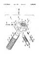
- FIG. 3is an enlarged view of the axle assembly of FIGS. 1 and 2;
- FIG. 3Ais an exploded isometric view of the axle assembly of FIG. 3;
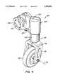
- FIG. 4is an enlarged view of the caster wheel assembly of FIGS. 1 and 2;
- FIG. 4Ais an exploded isometric view of the caster wheel assembly of FIG. 4;
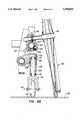
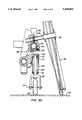
- FIGS. 5A-5Care partial cross-sectional views showing the axle assembly and caster wheel assembly when the drive wheel is at a 4° camber, an 8° camber, and a 12° camber, respectively.
- FIG. 1illustrates a wheelchair frame assembly 2, most of the components of which are also shown in FIG. 2.
- Assembly 2includes broadly a frame 4 having a pair of spaced-apart lower frame portions 6, each of which has a rear end 8 and a front end 10.
- a rear frame portion 12extends upwardly from rear end 8 of lower frame portion 6 and a front frame portion 14 extends upwardly from front end 10 of lower frame portion 6.
- the upper ends of front and rear frame portions 14, 12are coupled by seat portions 16.
- Seat portions 16are each pivotally mounted to the upper end of front frame portion 14 at a pivot 18 and adjustably mounted to one of several positions 20 along rear from portion 12 through use of a quick release pin 22.
- Each of the sides of frame 4are connected by lateral braces 24 and a footrest 26.
- An adjustable seat back support 28, shown in FIG. 1 only,is mounted to the rear end 30 of seat portion 16 and to rear frame portion 12 using a slider 32.
- a seat and backrestare mounted to frame assembly 2 during use but are not shown for simplicity
- FIGS. 3 and 3Aillustrate axle assembly 34 to include an axle adjustment member or tube 40 having a bore 42 sized to mount over and be secured to lower frame portion 6, typically by glue or other bonding agent.
- Tube 40has an outer surface 44 including axially extending splines 46 and a series of axially extending, circumferential grooves 48 formed within the splined outer surface 44.
- Axle assembly 34also includes an axle adjustment block 50 having a transverse bore 52 sized to house a generally cylindrical, adjustable axle lug 54. Together, axle adjustment block 50 and adjustable axle lug 54 constitute an axle housing 56. Lug 54 defines an axle bore 58 within which quick release axle 38 is housed.
- Axle adjustment block 50also includes a main bore 60 having a splined inner surface 62 constructed to mate with splines 46 on surface 44 of tube 40.
- splined inner surface 62 and splines 46 on surface 44contain ninety equally spaced splines, each spline spaced 4° apart. Since tube 40 is fixed to lower frame portion 6, the rotary orientation of block 50 relative to tube 40 determines the angular inclination of a drive wheel axis 64 defined by axle bore 58 and thus the cant of wheel 36. To aid the user in the proper rotary orientation of block 50 and tube 40, appropriate alignment lines can be drawn and labeled, for example 0°, 4°, 8°, 12°, on surface 44 of axle adjustment tube 40 for alignment with an appropriate index marker on axle adjustment block.
- Block 50is locked at a front-to-back position along surface 44 of tube 40 through the use of a quick release pin 66 mounted within a blind bore 68 which intersects main bore 60, as shown in FIGS. 5A-5C.
- Pin 60has a full diameter portion 70 and a reduced diameter portion 72, the end of full diameter portion 70 pressing against a compression coil spring 74 which normally biases pin 66 out of blind bore 68.
- a roll pin 76is pressed into a roll pin hole 78, formed transverse to blind bore 68, to intersect the blind bore and engage a shoulder 80 of pin 66 between portions 70, 72. Accordingly, when quick release pin 66 is in the locked or use position of FIG. 3, full diameter portion 70 is partially within main bore 60 and is in one of grooves 48 formed in surface 48 of tube 40.
- quick release pin 66To adjust the front/back position of drive wheel 36, the user simply presses on quick release pin 66 so to disengage full diameter portion 70 from groove 48, which permits axle housing 56 to slide along axle adjustment tube 40.
- quick release pin 66When the desired front/back position is achieved, quick release pin 66 is released and full diameter portion 70 snaps into the groove 48 with which it is aligned.
- Changing the camber of wheel 36is similar but axle housing 56 is moved in a forward direction until splined inner surface 62 completely disengages splines 46 to permit axle housing 56 to be rotated relative to tube 40 and then slid back onto tube 40 when the proper rotary orientation, and thus the proper camber, is achieved.
- adjustable axle lug 54has a set of circumferential grooves 84 formed in its outer surface. Grooves 84 are engaged by a quick release pin 86 housed within a blind bore 88 and biased outwardly by compression coil spring 90 in a manner similar to quick release pin 66. Pin 86 is kept from being urged completely out of hole 88 by a roll pin 92. Pressing on quick release pin 86 allows the user to adjust the position of axle lug 54 along drive wheel axis 64, thus changing the location of drive wheel hub 40 relative to frame 4.
- FIGS. 4 and 4Aillustrate a caster wheel assembly 94, including a two-piece caster spool housing 100 having a blind bore 102, see FIGS. 5A-5C, within which the generally cylindrical caster spool 104 of caster wheel 98 is housed.
- Housing 100includes a main portion 106 and a clamping portion 108 which define a cylindrical opening 110 sized to surround lower frame portion 6 adjacent front end 10 so to permit caster spool housing 100 to be clamped firmly to lower frame portion 6 using, for example, screws or bolts (not shown).
- Caster wheel 98includes a wheel 112 having a generally horizontal axis 114 mounted to a fork-like wheel mount 116 having a clevis portion 118 and a spindle portion 120 coaxial with pivot axis 96 and pivotally housed within caster spool 104.
- Caster wheel assembly 94also include a quick release pin 122 and a compression spring 124 housed within a blind bore 126 formed in housing 100; pin 122 is maintained within blind bore by a roll pin 128.
- Quick release pin 122when in its normal outwardly biased position of FIG. 4, engages one of three grooves 130 formed in the outer surface of caster spool 104 to adjust the position of caster spool 104 within blind bore 102 and thus the distance between wheel 112 and lower frame portion 6.
- FIG. 5Aillustrates drive wheel 36 at a 4° camber.
- quick release pin 122engages the upper most of grooves 130 to maintain caster wheel pivot axis 96 vertical. It has been found that this upper most groove 130 is also usable when drive wheel 36 is adjusted for a 0° camber; the difference in height of rear end 8 of lower frame portion 6 above support surface 132 when at a 0° camber and a 4° camber is very small (0.25%) so as not to require a separate groove 130 for both the 0° camber and the 4° camber.
- FIGS. 5B and 5Cillustrate drive wheel 36 at an 8° camber and a 12° camber, respectively. (Note that in FIGS.
- quick release axle 38is not shown.
- quick release pin 122engages a still lower groove 130, thus lowering front end 10 of lower frame portion 6 in an amount substantially equal to the distance rear end 8 of lower frame portion 6 is lowered at each of these different camber angles.
- the position of quick release pin 86 within one of groove 84 of adjustable axle lug 54is not changed. If desired, the position of lug 54 within transverse bore 52 can be changed to change the distance between hub 40 and lower frame portion 6 to accommodate the personal preferences of the user and ensure that top of drive wheel 36 does not rub against or otherwise interfere with frame 4.
- each drive wheel 36is adjusted by first removing drive wheel 36 from axle assembly 34 by removal of quick release axle 38.
- the rotary orientation of axle assembly 34, and thus the camber of drive wheel 36is adjusted by pressing on quick release pin 36 and sliding axle housing 56 in a forward direction, that is, towards caster wheel assembly 94, until splines 46 disengage from splined inner surface 62.
- Axle housing 56is then rotated the appropriate amount and slid back to re-engage splines 46 with splined inner surface 62.
- quick release pin 66is released to permit full diameter portion 72 to engage the appropriate groove 48, thus locking axle housing 56 in position.
- quick release pin 86is depressed and adjustable axle lug 54 is moved within transverse bore 52 until properly positioned, at which time pin 86 is released to lock lug 54 in place.
- Drive wheel 36can then be remounted to axle housing 56 using quick release axle 38 passing through drive wheel hub 39.
- the height of front end 10 of lower frame portion 6 above support surface 132can be adjusted by pressing on quick release pin 122, moving caster spool 104 within blind bore 102 and releasing quick release pin 122 when aligned with the appropriate groove 130.
- quick release pins engaging circumferential groovesare the toolless means for permitting many of the manual adjustments of axle assembly 34 and caster wheel assembly 94.
- other types of toolless engagement devicescould be used, such as having the ends of spring-biased pins engaging holes or other depressions in the object to be locked in place.
- Various thumb screw type, detented twist lock fastenerscould be used instead of quick release pins to engage or disengage various grooves according to whether the object is to be moved or locked in place.
- tube 40could be pinned in place at both ends allowing, for example, 1° shifts in the rotary orientation of the tube to permit adjustments in the camber at other than the set 4° increments available with the disclosed embodiment.
- Caster spool 104 and axle lug 54are shown to be generally cylindrical; they, along with their mating bores, could have shapes other than cylindrical, such as D-shaped; caster spool 104 and axle lug 54 need not rotate within their bores since spindle portion 120 and axle 38 provide the necessary rotation about axis 96 and axis 64, respectively.
Landscapes
- Life Sciences & Earth Sciences (AREA)
- Animal Behavior & Ethology (AREA)
- General Health & Medical Sciences (AREA)
- Public Health (AREA)
- Veterinary Medicine (AREA)
- Health & Medical Sciences (AREA)
- Carriages For Children, Sleds, And Other Hand-Operated Vehicles (AREA)
- Automatic Cycles, And Cycles In General (AREA)
- Handcart (AREA)
- Vehicle Body Suspensions (AREA)
- Materials For Medical Uses (AREA)
- Other Liquid Machine Or Engine Such As Wave Power Use (AREA)
- Golf Clubs (AREA)
- Tents Or Canopies (AREA)
- Seats For Vehicles (AREA)
- Preparing Plates And Mask In Photomechanical Process (AREA)
Abstract
Description
Claims (22)
Priority Applications (14)
| Application Number | Priority Date | Filing Date | Title |
|---|---|---|---|
| US08/365,261US5590893A (en) | 1994-12-28 | 1994-12-28 | Wheelchair frame assembly |
| DK95944264TDK0800380T3 (en) | 1994-12-28 | 1995-12-27 | Wheelchair shaft construction |
| EP95944264AEP0800380B1 (en) | 1994-12-28 | 1995-12-27 | Axle assembly for wheelchair |
| PCT/US1995/017012WO1996019961A1 (en) | 1994-12-28 | 1995-12-27 | Improved wheelchair |
| US08/579,483US6027132A (en) | 1994-12-28 | 1995-12-27 | Wheelchair |
| EP98109123AEP0867165A1 (en) | 1994-12-28 | 1995-12-27 | Wheelchair |
| ES95944264TES2131352T3 (en) | 1994-12-28 | 1995-12-27 | AXLE ASSEMBLY FOR WHEELCHAIR. |
| CA002209081ACA2209081A1 (en) | 1994-12-28 | 1995-12-27 | Improved wheelchair |
| JP8520602AJPH10513066A (en) | 1994-12-28 | 1995-12-27 | Improved wheelchair |
| AU46105/96AAU700650B2 (en) | 1994-12-28 | 1995-12-27 | Improved wheelchair |
| DE69508280TDE69508280T2 (en) | 1994-12-28 | 1995-12-27 | AXLE STRUCTURE FOR WHEELCHAIR |
| AT95944264TATE177314T1 (en) | 1994-12-28 | 1995-12-27 | AXLE STRUCTURE FOR WHEELCHAIR |
| MXPA/A/1997/004843AMXPA97004843A (en) | 1994-12-28 | 1997-06-26 | Best wheelchair |
| US08/944,810US5997021A (en) | 1994-12-28 | 1997-10-06 | Adjustable seat back assembly for a wheelchair |
Applications Claiming Priority (1)
| Application Number | Priority Date | Filing Date | Title |
|---|---|---|---|
| US08/365,261US5590893A (en) | 1994-12-28 | 1994-12-28 | Wheelchair frame assembly |
Related Child Applications (1)
| Application Number | Title | Priority Date | Filing Date |
|---|---|---|---|
| US08/579,483Continuation-In-PartUS6027132A (en) | 1994-12-28 | 1995-12-27 | Wheelchair |
Publications (1)
| Publication Number | Publication Date |
|---|---|
| US5590893Atrue US5590893A (en) | 1997-01-07 |
Family
ID=23438134
Family Applications (2)
| Application Number | Title | Priority Date | Filing Date |
|---|---|---|---|
| US08/365,261Expired - Fee RelatedUS5590893A (en) | 1994-12-28 | 1994-12-28 | Wheelchair frame assembly |
| US08/579,483Expired - Fee RelatedUS6027132A (en) | 1994-12-28 | 1995-12-27 | Wheelchair |
Family Applications After (1)
| Application Number | Title | Priority Date | Filing Date |
|---|---|---|---|
| US08/579,483Expired - Fee RelatedUS6027132A (en) | 1994-12-28 | 1995-12-27 | Wheelchair |
Country Status (10)
| Country | Link |
|---|---|
| US (2) | US5590893A (en) |
| EP (2) | EP0867165A1 (en) |
| JP (1) | JPH10513066A (en) |
| AT (1) | ATE177314T1 (en) |
| AU (1) | AU700650B2 (en) |
| CA (1) | CA2209081A1 (en) |
| DE (1) | DE69508280T2 (en) |
| DK (1) | DK0800380T3 (en) |
| ES (1) | ES2131352T3 (en) |
| WO (1) | WO1996019961A1 (en) |
Cited By (56)
| Publication number | Priority date | Publication date | Assignee | Title |
|---|---|---|---|---|
| US5727802A (en)* | 1994-07-14 | 1998-03-17 | Everest & Jennings International Ltd. | Suspension wheelchair and wheelchair frame |
| USD411149S (en) | 1998-11-20 | 1999-06-22 | Shih-Yi Huang | Framework for wheelchair |
| US5997021A (en)* | 1994-12-28 | 1999-12-07 | Sunrise Medical Hhg Inc. | Adjustable seat back assembly for a wheelchair |
| US6027132A (en)* | 1994-12-28 | 2000-02-22 | Sunrise Medical Hhg Inc. | Wheelchair |
| US6155583A (en)* | 1998-01-14 | 2000-12-05 | Koike; Shozo | Wheelchair |
| US6158757A (en)* | 1997-07-24 | 2000-12-12 | Tidcomb; Steven | Motion conversion assembly and vehicle |
| US6168177B1 (en)* | 1997-06-27 | 2001-01-02 | Otto Bock Orthopadische Industrie Gmbh & Co. | Wheel camber adapter for a wheelchair |
| US6189906B1 (en)* | 1998-02-27 | 2001-02-20 | Otto Bock Orthopaedische Industrie Besitz-Und Verwaltungs-Kommanditgesellschaft | Wheelchair having a single tube bend |
| US6217052B1 (en) | 1999-06-14 | 2001-04-17 | Sunrise Medical Whg Inc. | Notched axle bracket support for a wheelchair |
| US6264225B1 (en) | 1999-06-14 | 2001-07-24 | Sunrise Medical Hhg Inc. | Adjustable side frame and wheelchair with adjustable side frame |
| US6264218B1 (en)* | 1999-06-14 | 2001-07-24 | Sunrise Medical Hhg Inc. | Adjustable wheelchair frame |
| US6318751B1 (en) | 1999-06-14 | 2001-11-20 | Sunrise Medical Hhg Inc. | Angled axle bracket for a wheelchair |
| US6715845B2 (en)* | 1999-06-03 | 2004-04-06 | Deka Products Limited Partnership | Mechanical improvements to a personal vehicle |
| US20060042891A1 (en)* | 2004-08-27 | 2006-03-02 | Larson Eric W | Wheelchair with hands-free control |
| US20060066143A1 (en)* | 2002-03-13 | 2006-03-30 | Invacare Corporation | Adjustable seating system |
| US20060087103A1 (en)* | 2004-01-23 | 2006-04-27 | Sunrise Medical Hhg Inc. | Foldable wheelchair and axle plate therefor |
| WO2007112508A1 (en) | 2006-04-04 | 2007-10-11 | Lu Papi & Associates Pty Ltd | Wheelchair |
| US20090146389A1 (en)* | 2005-03-30 | 2009-06-11 | Jaimie Borisoff | Wheelchair |
| US20100038880A1 (en)* | 2008-08-15 | 2010-02-18 | Bagg Christian Peter Edward | Modular and/or configurable wheelchair apparatus |
| US20110006582A1 (en)* | 2008-03-05 | 2011-01-13 | Tamarack Habilitation Technologies, Inc. | Seat cushion |
| US20110291387A1 (en)* | 2010-05-26 | 2011-12-01 | Chang Liao Yuan-Chieh | Foldable wheelchair |
| US8348293B1 (en)* | 2010-03-17 | 2013-01-08 | William Lasher | Wheelchair with easily changeable wheel sets |
| US20130300083A1 (en)* | 2012-05-10 | 2013-11-14 | Jaimie Borisoff | Wheelchair and frame for a wheelchair |
| US20150150737A1 (en)* | 2006-02-06 | 2015-06-04 | Michael Jeffrey Spindle | Wheelchairs and Wheeled Vehicles |
| US9592169B2 (en)* | 2014-10-20 | 2017-03-14 | Medline Industries, Inc | Compact wheelchair assembly with removable wheels and methods therefor |
| US20180353356A1 (en)* | 2016-01-28 | 2018-12-13 | Todo Works Co., Ltd. | Attaching and detaching type driving device and wheelchair having the same |
| US10188890B2 (en) | 2013-12-26 | 2019-01-29 | Icon Health & Fitness, Inc. | Magnetic resistance mechanism in a cable machine |
| US10252109B2 (en) | 2016-05-13 | 2019-04-09 | Icon Health & Fitness, Inc. | Weight platform treadmill |
| US10258828B2 (en) | 2015-01-16 | 2019-04-16 | Icon Health & Fitness, Inc. | Controls for an exercise device |
| US10272317B2 (en) | 2016-03-18 | 2019-04-30 | Icon Health & Fitness, Inc. | Lighted pace feature in a treadmill |
| US10279212B2 (en) | 2013-03-14 | 2019-05-07 | Icon Health & Fitness, Inc. | Strength training apparatus with flywheel and related methods |
| US10293211B2 (en) | 2016-03-18 | 2019-05-21 | Icon Health & Fitness, Inc. | Coordinated weight selection |
| US10343017B2 (en) | 2016-11-01 | 2019-07-09 | Icon Health & Fitness, Inc. | Distance sensor for console positioning |
| US10376736B2 (en) | 2016-10-12 | 2019-08-13 | Icon Health & Fitness, Inc. | Cooling an exercise device during a dive motor runway condition |
| US10426989B2 (en) | 2014-06-09 | 2019-10-01 | Icon Health & Fitness, Inc. | Cable system incorporated into a treadmill |
| US10433612B2 (en) | 2014-03-10 | 2019-10-08 | Icon Health & Fitness, Inc. | Pressure sensor to quantify work |
| US10441844B2 (en) | 2016-07-01 | 2019-10-15 | Icon Health & Fitness, Inc. | Cooling systems and methods for exercise equipment |
| US10471299B2 (en) | 2016-07-01 | 2019-11-12 | Icon Health & Fitness, Inc. | Systems and methods for cooling internal exercise equipment components |
| US10493349B2 (en) | 2016-03-18 | 2019-12-03 | Icon Health & Fitness, Inc. | Display on exercise device |
| US10500473B2 (en) | 2016-10-10 | 2019-12-10 | Icon Health & Fitness, Inc. | Console positioning |
| US10543395B2 (en) | 2016-12-05 | 2020-01-28 | Icon Health & Fitness, Inc. | Offsetting treadmill deck weight during operation |
| US10561894B2 (en) | 2016-03-18 | 2020-02-18 | Icon Health & Fitness, Inc. | Treadmill with removable supports |
| US10625137B2 (en) | 2016-03-18 | 2020-04-21 | Icon Health & Fitness, Inc. | Coordinated displays in an exercise device |
| US10661114B2 (en) | 2016-11-01 | 2020-05-26 | Icon Health & Fitness, Inc. | Body weight lift mechanism on treadmill |
| US10702431B1 (en)* | 2016-02-25 | 2020-07-07 | Ki Mobility | Keyed and indexed embossed tube and taper lock system |
| US10729965B2 (en) | 2017-12-22 | 2020-08-04 | Icon Health & Fitness, Inc. | Audible belt guide in a treadmill |
| US10751235B2 (en)* | 2017-04-14 | 2020-08-25 | Chad Robert Ernst | Adjustable camber wheelchair devices, systems and methods |
| US10953305B2 (en) | 2015-08-26 | 2021-03-23 | Icon Health & Fitness, Inc. | Strength exercise mechanisms |
| US11203230B2 (en)* | 2018-09-06 | 2021-12-21 | Invacare International Gmbh | Caster wheel support assembly for a wheelchair and wheelchair comprising the same |
| US11259974B1 (en) | 2016-02-25 | 2022-03-01 | Ki Mobility Llc | Dampening system for wheelchair and wheelchair therewith |
| US11451108B2 (en) | 2017-08-16 | 2022-09-20 | Ifit Inc. | Systems and methods for axial impact resistance in electric motors |
| US11685188B2 (en)* | 2016-11-10 | 2023-06-27 | Exokinetics, Inc. | Dual-state caster and method |
| WO2023146661A1 (en)* | 2022-01-26 | 2023-08-03 | Permobil, Inc. | Wheelchair |
| US12161601B2 (en) | 2018-02-20 | 2024-12-10 | Angel Rodriguez-Cruz | Wheeleta |
| USD1054331S1 (en) | 2022-01-26 | 2024-12-17 | Permobil, Inc. | Wheelchair |
| USD1054330S1 (en) | 2022-01-26 | 2024-12-17 | Permobil, Inc. | Wheelchair |
Families Citing this family (30)
| Publication number | Priority date | Publication date | Assignee | Title |
|---|---|---|---|---|
| EP0824907A1 (en)* | 1996-08-21 | 1998-02-25 | Meyra Wilhelm Meyer Gmbh & Co. Kg | Device for adjusting the camber of wheelchairs |
| US5851018A (en)* | 1996-11-12 | 1998-12-22 | Invacare Corporation | Camber adjustment assembly for a wheelchair |
| GB2347655A (en)* | 1999-03-12 | 2000-09-13 | Sunrise Medical Ltd | Wheelchair with adjustable camber angle |
| US6273445B1 (en)* | 1999-06-14 | 2001-08-14 | Sunrise Medical Hhg Inc. | Wheel mounting assembly and wheelchair therewith |
| US6352273B1 (en)* | 1999-10-29 | 2002-03-05 | Sunrise Medical Hhg Inc. | Seat mounting assembly |
| US6302429B1 (en)* | 1999-11-16 | 2001-10-16 | Da International, Ltd | Convertible wheelchair |
| US6394476B1 (en) | 2000-08-10 | 2002-05-28 | Invacare Corporation | Wheelchair seat having adjustable telescoping assembly |
| US6776433B2 (en) | 2000-08-22 | 2004-08-17 | Richard J. Harrison | Assistive mobility device |
| US20090194975A1 (en)* | 2000-08-22 | 2009-08-06 | Harrison Richard J | Assistive mobility device |
| US6428033B1 (en)* | 2000-08-22 | 2002-08-06 | R & W Ventures, Inc | Assistive mobility device |
| DE10136369C2 (en)* | 2001-07-26 | 2003-05-28 | Alber Ulrich Gmbh & Co Kg | Small vehicle, especially a wheelchair |
| DE10136368C2 (en)* | 2001-07-26 | 2003-05-28 | Alber Ulrich Gmbh & Co Kg | Small vehicle, especially a wheelchair |
| US6976278B2 (en) | 2002-09-10 | 2005-12-20 | Martha Oetting | Commode for wheelchair |
| EP1769783A1 (en) | 2005-09-29 | 2007-04-04 | Invacare International Sàrl | Device for adjusting the seat back angle in a wheelchair and a wheelchair comprising such a device |
| CN2875405Y (en)* | 2006-01-26 | 2007-03-07 | 佛山市南海建泰铝制品有限公司 | Folding walking-aid cart |
| USD559741S1 (en)* | 2006-03-03 | 2008-01-15 | Lasher Sport, Llc | Wheelchair |
| DE102006013910B3 (en)* | 2006-03-25 | 2007-07-26 | Otto Bock Healthcare Ip Gmbh & Co. Kg | Wheelchair, with a rear structure to prevent tipping backwards, has swing struts with support rollers at the ends of the rear axle to swing out for use and fold inwards when not required |
| TWM308748U (en)* | 2006-05-19 | 2007-04-01 | Link Treasure Ltd | Foldable walker frame |
| US8152192B2 (en)* | 2007-06-19 | 2012-04-10 | Pat Dougherty | All terrain adapter for a wheelchair |
| US7735847B2 (en)* | 2007-06-19 | 2010-06-15 | Dougherty Patrick S | All terrain adapter for a wheelchair |
| US7896385B2 (en)* | 2007-09-21 | 2011-03-01 | Michael Every | Foldable wheelchair |
| DE102010017349B4 (en)* | 2010-06-14 | 2012-05-16 | Sunrise Medical Gmbh & Co. Kg | Height-adjustable wheel suspension device and wheelchair with such a device |
| ITTO20130613A1 (en)* | 2013-07-19 | 2015-01-20 | Lab 3 11 S A S | WHEELCHAIR FOR SPORTS ACTIVITIES |
| US9241852B2 (en) | 2013-11-21 | 2016-01-26 | Patrick S. Dougherty | All terrain adapter for folding wheelchair |
| EP3034056B1 (en)* | 2014-12-18 | 2017-11-29 | Permobil AB | Seat arrangement and electrically powered wheelchair comprising the same |
| US10076457B2 (en)* | 2016-08-01 | 2018-09-18 | Eric Behm | Propulsion attachment for a manual wheelchair |
| ES2857722T3 (en)* | 2018-02-14 | 2021-09-29 | Batec Mobility S L | Auxiliary chassis systems for wheelchairs |
| KR101890926B1 (en)* | 2018-03-29 | 2018-08-22 | 윈엔윈(주) | Wheel chair of athletics |
| PL427110A1 (en)* | 2018-09-18 | 2019-07-29 | Pare Spółka Z Ograniczoną Odpowiedzialnością | Adjustment mechanism of gravity centre, preferably of a wheelchair |
| CA3168572A1 (en) | 2022-07-13 | 2024-01-13 | Invacare Corporation | Wheelchair and suspension systems |
Citations (30)
| Publication number | Priority date | Publication date | Assignee | Title |
|---|---|---|---|---|
| CA501986A (en)* | 1954-05-04 | A. Linquist William | Wheel chair | |
| US3379450A (en)* | 1966-04-28 | 1968-04-23 | Technical Mfg Corp | Adjustable wheelchair device |
| US3882949A (en)* | 1972-11-16 | 1975-05-13 | Us Health | Universal wheelchair for the severely disabled |
| USD254970S (en) | 1978-03-29 | 1980-05-13 | Sony Corporation | Wheelchair |
| US4405142A (en)* | 1981-03-09 | 1983-09-20 | Stainless Medical Products, Inc. | Knock down wheel chair |
| US4477098A (en)* | 1980-11-13 | 1984-10-16 | Quadra Wheelchairs, Inc. | Wheelchair construction |
| USD278217S (en) | 1982-12-10 | 1985-04-02 | Everest & Jennings, Inc. | Wheelchair |
| US4650201A (en)* | 1984-10-22 | 1987-03-17 | Peterson, Wicks, Nemer & Kamrath, P.A. | Lightweight wheelchair |
| US4652005A (en)* | 1984-10-22 | 1987-03-24 | Peterson, Wicks, Nemer & Kamrath, P.A. | Lightweight wheelchair |
| US4721321A (en)* | 1982-11-16 | 1988-01-26 | Invacare Corporation | Wheelchair with adjustable rear canes |
| US4730842A (en)* | 1986-04-18 | 1988-03-15 | Wheel Ring, Inc. | Adjustable wheelchair |
| US4768797A (en)* | 1987-01-28 | 1988-09-06 | Everest & Jennings | Folding wheelchair having adjustable wheels and armrests |
| US4805925A (en)* | 1982-11-16 | 1989-02-21 | Invacare Corporation | Adjustable rear wheel mounting assembly for wheelchairs |
| US4813963A (en)* | 1987-08-24 | 1989-03-21 | Zimmer, Inc. | Femoral component for a hip prosthesis |
| EP0312969A2 (en)* | 1987-10-19 | 1989-04-26 | Mulholland Designs, Inc. | Adjustable frame wheelchair |
| USD306712S (en) | 1987-12-14 | 1990-03-20 | Everest & Jennings, Inc. | Wheelchair frame |
| US4955624A (en)* | 1989-04-26 | 1990-09-11 | Jeun Long Guo | Wheelchair with height adjustable seat |
| US4966379A (en)* | 1987-10-19 | 1990-10-30 | Mulholland Designs, Inc. | Reclinable wheelchair |
| US4969232A (en)* | 1989-08-03 | 1990-11-13 | Everest & Jennings, Inc. | Adjustable caster wheel assembly |
| US4989890A (en)* | 1986-09-30 | 1991-02-05 | Invacare Corporation | Length and width adjustable wheelchair |
| US5020816A (en)* | 1987-10-19 | 1991-06-04 | Mulholland Designs, Inc. | Adjustable frame wheelchair |
| US5028064A (en)* | 1989-02-10 | 1991-07-02 | Johnson John W | Racing wheelchair |
| US5060962A (en)* | 1990-05-21 | 1991-10-29 | Everest & Jennings, Inc. | Rear wheel camber sleeve assembly for a wheelchair |
| US5131672A (en)* | 1990-04-27 | 1992-07-21 | Medical Composite Technology | Camber adjustment fitting for a wheelchair |
| US5152543A (en)* | 1990-11-15 | 1992-10-06 | Everest & Jennings, Inc | Composite frame wheelchair |
| US5253888A (en)* | 1993-04-02 | 1993-10-19 | Da International, Ltd. | Rigid frame weldless wheelchair |
| US5259635A (en)* | 1989-09-29 | 1993-11-09 | Sherwood Drolet Corporation Ltd | Wheelchair |
| US5267745A (en)* | 1991-11-08 | 1993-12-07 | Medical Composite Technology, Inc. | Wheelchair and wheelchair frame |
| USD344702S (en) | 1992-10-30 | 1994-03-01 | Medical Composite Technology, Inc. | Modular wheelchair frame |
| US5333894A (en)* | 1993-05-17 | 1994-08-02 | Douglas Mayes | Wheel mounting apparatus for wheelchairs |
Family Cites Families (17)
| Publication number | Priority date | Publication date | Assignee | Title |
|---|---|---|---|---|
| US1342500A (en)* | 1916-04-07 | 1920-06-08 | Belt Grip Pulley Company | Caster |
| US1274165A (en)* | 1916-10-05 | 1918-07-30 | Solomon Himmel | Caster. |
| US1482954A (en)* | 1921-12-10 | 1924-02-05 | United Electric Company | Adjustable caster |
| US1491204A (en)* | 1923-03-03 | 1924-04-22 | Carl A Epting | Caster |
| GB456271A (en)* | 1936-04-17 | 1936-11-05 | Charles John Katenkam | Improvements in adjustable and collapsible chairs |
| US2565867A (en)* | 1944-06-20 | 1951-08-28 | Lundquist Carl Ernst Edvard | Locking device for chairs |
| US2918300A (en)* | 1958-01-31 | 1959-12-22 | Charles C Hendrickson | Caster wheel assembly for a disc tiller |
| US3784252A (en)* | 1971-12-27 | 1974-01-08 | Peterson Baby Prod Co | Seat back adjustment mechanism for baby products |
| US3866250A (en)* | 1973-09-19 | 1975-02-18 | John Guythar Bradford | Adjustable back-rest |
| FR2563993A1 (en)* | 1984-05-11 | 1985-11-15 | Quadra Wheelchairs Inc | Collapsible and foldable wheelchair |
| DE3517050A1 (en)* | 1985-05-11 | 1986-11-13 | Erich 6837 St Leon-Rot Purkott | Wheel-chair, especially for sports purposes |
| US4813693A (en)* | 1986-09-30 | 1989-03-21 | Invacare Corporation | Adjustable child's wheelchair |
| DE8631974U1 (en)* | 1986-11-28 | 1987-04-16 | MEYRA Wilhelm Meyer GmbH & Co KG, 4925 Kalletal | Hospital elevator |
| DE69230623T2 (en)* | 1991-02-20 | 2000-06-08 | Sunrise Medical Hhg Inc., Longmont | Backrest system for distortions |
| AU5666994A (en)* | 1992-11-12 | 1994-06-08 | Michael D. Doom | T-configured wheelchair |
| US5551756A (en)* | 1994-03-16 | 1996-09-03 | Custom Orthotics, Inc. | Orthotic wheelchair positioning device and support system |
| US5590893A (en)* | 1994-12-28 | 1997-01-07 | No Limit Designs, Inc. | Wheelchair frame assembly |
- 1994
- 1994-12-28USUS08/365,261patent/US5590893A/ennot_activeExpired - Fee Related
- 1995
- 1995-12-27ESES95944264Tpatent/ES2131352T3/ennot_activeExpired - Lifetime
- 1995-12-27JPJP8520602Apatent/JPH10513066A/enactivePending
- 1995-12-27USUS08/579,483patent/US6027132A/ennot_activeExpired - Fee Related
- 1995-12-27EPEP98109123Apatent/EP0867165A1/ennot_activeWithdrawn
- 1995-12-27EPEP95944264Apatent/EP0800380B1/ennot_activeExpired - Lifetime
- 1995-12-27ATAT95944264Tpatent/ATE177314T1/ennot_activeIP Right Cessation
- 1995-12-27DEDE69508280Tpatent/DE69508280T2/ennot_activeExpired - Fee Related
- 1995-12-27DKDK95944264Tpatent/DK0800380T3/enactive
- 1995-12-27AUAU46105/96Apatent/AU700650B2/ennot_activeCeased
- 1995-12-27CACA002209081Apatent/CA2209081A1/ennot_activeAbandoned
- 1995-12-27WOPCT/US1995/017012patent/WO1996019961A1/enactiveIP Right Grant
Patent Citations (31)
| Publication number | Priority date | Publication date | Assignee | Title |
|---|---|---|---|---|
| CA501986A (en)* | 1954-05-04 | A. Linquist William | Wheel chair | |
| US3379450A (en)* | 1966-04-28 | 1968-04-23 | Technical Mfg Corp | Adjustable wheelchair device |
| US3882949A (en)* | 1972-11-16 | 1975-05-13 | Us Health | Universal wheelchair for the severely disabled |
| USD254970S (en) | 1978-03-29 | 1980-05-13 | Sony Corporation | Wheelchair |
| US4477098A (en)* | 1980-11-13 | 1984-10-16 | Quadra Wheelchairs, Inc. | Wheelchair construction |
| US4405142A (en)* | 1981-03-09 | 1983-09-20 | Stainless Medical Products, Inc. | Knock down wheel chair |
| US4721321A (en)* | 1982-11-16 | 1988-01-26 | Invacare Corporation | Wheelchair with adjustable rear canes |
| US4805925A (en)* | 1982-11-16 | 1989-02-21 | Invacare Corporation | Adjustable rear wheel mounting assembly for wheelchairs |
| USD278217S (en) | 1982-12-10 | 1985-04-02 | Everest & Jennings, Inc. | Wheelchair |
| US4650201A (en)* | 1984-10-22 | 1987-03-17 | Peterson, Wicks, Nemer & Kamrath, P.A. | Lightweight wheelchair |
| US4652005A (en)* | 1984-10-22 | 1987-03-24 | Peterson, Wicks, Nemer & Kamrath, P.A. | Lightweight wheelchair |
| US4730842A (en)* | 1986-04-18 | 1988-03-15 | Wheel Ring, Inc. | Adjustable wheelchair |
| US4989890A (en)* | 1986-09-30 | 1991-02-05 | Invacare Corporation | Length and width adjustable wheelchair |
| US4768797A (en)* | 1987-01-28 | 1988-09-06 | Everest & Jennings | Folding wheelchair having adjustable wheels and armrests |
| US4813963A (en)* | 1987-08-24 | 1989-03-21 | Zimmer, Inc. | Femoral component for a hip prosthesis |
| EP0312969A2 (en)* | 1987-10-19 | 1989-04-26 | Mulholland Designs, Inc. | Adjustable frame wheelchair |
| US4966379A (en)* | 1987-10-19 | 1990-10-30 | Mulholland Designs, Inc. | Reclinable wheelchair |
| US5020816A (en)* | 1987-10-19 | 1991-06-04 | Mulholland Designs, Inc. | Adjustable frame wheelchair |
| USD306712S (en) | 1987-12-14 | 1990-03-20 | Everest & Jennings, Inc. | Wheelchair frame |
| US5028064A (en)* | 1989-02-10 | 1991-07-02 | Johnson John W | Racing wheelchair |
| US4955624A (en)* | 1989-04-26 | 1990-09-11 | Jeun Long Guo | Wheelchair with height adjustable seat |
| US4969232A (en)* | 1989-08-03 | 1990-11-13 | Everest & Jennings, Inc. | Adjustable caster wheel assembly |
| US5259635A (en)* | 1989-09-29 | 1993-11-09 | Sherwood Drolet Corporation Ltd | Wheelchair |
| US5131672A (en)* | 1990-04-27 | 1992-07-21 | Medical Composite Technology | Camber adjustment fitting for a wheelchair |
| US5060962A (en)* | 1990-05-21 | 1991-10-29 | Everest & Jennings, Inc. | Rear wheel camber sleeve assembly for a wheelchair |
| US5152543A (en)* | 1990-11-15 | 1992-10-06 | Everest & Jennings, Inc | Composite frame wheelchair |
| US5267745A (en)* | 1991-11-08 | 1993-12-07 | Medical Composite Technology, Inc. | Wheelchair and wheelchair frame |
| US5409247A (en)* | 1991-11-08 | 1995-04-25 | Robertson; A. Scott | Wheelchair frame |
| USD344702S (en) | 1992-10-30 | 1994-03-01 | Medical Composite Technology, Inc. | Modular wheelchair frame |
| US5253888A (en)* | 1993-04-02 | 1993-10-19 | Da International, Ltd. | Rigid frame weldless wheelchair |
| US5333894A (en)* | 1993-05-17 | 1994-08-02 | Douglas Mayes | Wheel mounting apparatus for wheelchairs |
Non-Patent Citations (1)
| Title |
|---|
| Action Pro product literature, pp. 10, 11, update Aug. 31, 1993.* |
Cited By (67)
| Publication number | Priority date | Publication date | Assignee | Title |
|---|---|---|---|---|
| US5727802A (en)* | 1994-07-14 | 1998-03-17 | Everest & Jennings International Ltd. | Suspension wheelchair and wheelchair frame |
| US6027132A (en)* | 1994-12-28 | 2000-02-22 | Sunrise Medical Hhg Inc. | Wheelchair |
| US5997021A (en)* | 1994-12-28 | 1999-12-07 | Sunrise Medical Hhg Inc. | Adjustable seat back assembly for a wheelchair |
| US6168177B1 (en)* | 1997-06-27 | 2001-01-02 | Otto Bock Orthopadische Industrie Gmbh & Co. | Wheel camber adapter for a wheelchair |
| US6158757A (en)* | 1997-07-24 | 2000-12-12 | Tidcomb; Steven | Motion conversion assembly and vehicle |
| US6155583A (en)* | 1998-01-14 | 2000-12-05 | Koike; Shozo | Wheelchair |
| US6189906B1 (en)* | 1998-02-27 | 2001-02-20 | Otto Bock Orthopaedische Industrie Besitz-Und Verwaltungs-Kommanditgesellschaft | Wheelchair having a single tube bend |
| USD411149S (en) | 1998-11-20 | 1999-06-22 | Shih-Yi Huang | Framework for wheelchair |
| US6715845B2 (en)* | 1999-06-03 | 2004-04-06 | Deka Products Limited Partnership | Mechanical improvements to a personal vehicle |
| US6217052B1 (en) | 1999-06-14 | 2001-04-17 | Sunrise Medical Whg Inc. | Notched axle bracket support for a wheelchair |
| US6264225B1 (en) | 1999-06-14 | 2001-07-24 | Sunrise Medical Hhg Inc. | Adjustable side frame and wheelchair with adjustable side frame |
| US6264218B1 (en)* | 1999-06-14 | 2001-07-24 | Sunrise Medical Hhg Inc. | Adjustable wheelchair frame |
| US6318751B1 (en) | 1999-06-14 | 2001-11-20 | Sunrise Medical Hhg Inc. | Angled axle bracket for a wheelchair |
| US7192042B2 (en) | 2002-03-13 | 2007-03-20 | Invacare Corporation | Adjustable seating system |
| US20060066143A1 (en)* | 2002-03-13 | 2006-03-30 | Invacare Corporation | Adjustable seating system |
| US7360781B2 (en)* | 2004-01-23 | 2008-04-22 | Sunrise Medical Hhg Inc. | Foldable wheelchair and axle plate therefor |
| US20060087103A1 (en)* | 2004-01-23 | 2006-04-27 | Sunrise Medical Hhg Inc. | Foldable wheelchair and axle plate therefor |
| US20060042891A1 (en)* | 2004-08-27 | 2006-03-02 | Larson Eric W | Wheelchair with hands-free control |
| US20090146389A1 (en)* | 2005-03-30 | 2009-06-11 | Jaimie Borisoff | Wheelchair |
| US7845665B2 (en) | 2005-03-30 | 2010-12-07 | Jaimie Borisoff | Wheelchair |
| US9381124B2 (en)* | 2006-02-06 | 2016-07-05 | Michael Jeffrey Spindle | Wheelchairs and wheeled vehicles |
| US20150150737A1 (en)* | 2006-02-06 | 2015-06-04 | Michael Jeffrey Spindle | Wheelchairs and Wheeled Vehicles |
| US8573622B2 (en)* | 2006-04-04 | 2013-11-05 | Lu Papi & Associates Pty Ltd | Wheelchair |
| WO2007112508A1 (en) | 2006-04-04 | 2007-10-11 | Lu Papi & Associates Pty Ltd | Wheelchair |
| US20100007114A1 (en)* | 2006-04-04 | 2010-01-14 | Luciano Papi | Wheelchair |
| US20110006582A1 (en)* | 2008-03-05 | 2011-01-13 | Tamarack Habilitation Technologies, Inc. | Seat cushion |
| US8177302B2 (en)* | 2008-03-05 | 2012-05-15 | Tamarack Habilitation Technologies | Seat cushion |
| US20100038880A1 (en)* | 2008-08-15 | 2010-02-18 | Bagg Christian Peter Edward | Modular and/or configurable wheelchair apparatus |
| US8348293B1 (en)* | 2010-03-17 | 2013-01-08 | William Lasher | Wheelchair with easily changeable wheel sets |
| US20110291387A1 (en)* | 2010-05-26 | 2011-12-01 | Chang Liao Yuan-Chieh | Foldable wheelchair |
| US20130300083A1 (en)* | 2012-05-10 | 2013-11-14 | Jaimie Borisoff | Wheelchair and frame for a wheelchair |
| US8801020B2 (en)* | 2012-05-10 | 2014-08-12 | Jaimie Borisoff | Wheelchair and frame for a wheelchair |
| US10279212B2 (en) | 2013-03-14 | 2019-05-07 | Icon Health & Fitness, Inc. | Strength training apparatus with flywheel and related methods |
| US10188890B2 (en) | 2013-12-26 | 2019-01-29 | Icon Health & Fitness, Inc. | Magnetic resistance mechanism in a cable machine |
| US10433612B2 (en) | 2014-03-10 | 2019-10-08 | Icon Health & Fitness, Inc. | Pressure sensor to quantify work |
| US10426989B2 (en) | 2014-06-09 | 2019-10-01 | Icon Health & Fitness, Inc. | Cable system incorporated into a treadmill |
| US9592169B2 (en)* | 2014-10-20 | 2017-03-14 | Medline Industries, Inc | Compact wheelchair assembly with removable wheels and methods therefor |
| US9901498B2 (en)* | 2014-10-20 | 2018-02-27 | Medline Industries, Inc. | Compact wheelchair assembly with removable wheels and methods therefor |
| USD782372S1 (en) | 2014-10-20 | 2017-03-28 | Medline Industries, Inc. | Chassis for a wheelchair |
| US10258828B2 (en) | 2015-01-16 | 2019-04-16 | Icon Health & Fitness, Inc. | Controls for an exercise device |
| US10953305B2 (en) | 2015-08-26 | 2021-03-23 | Icon Health & Fitness, Inc. | Strength exercise mechanisms |
| US10849803B2 (en)* | 2016-01-28 | 2020-12-01 | Todo Works Co., Ltd. | Attaching and detaching type driving device and wheelchair having the same |
| US20180353356A1 (en)* | 2016-01-28 | 2018-12-13 | Todo Works Co., Ltd. | Attaching and detaching type driving device and wheelchair having the same |
| US11259974B1 (en) | 2016-02-25 | 2022-03-01 | Ki Mobility Llc | Dampening system for wheelchair and wheelchair therewith |
| US10702431B1 (en)* | 2016-02-25 | 2020-07-07 | Ki Mobility | Keyed and indexed embossed tube and taper lock system |
| US10272317B2 (en) | 2016-03-18 | 2019-04-30 | Icon Health & Fitness, Inc. | Lighted pace feature in a treadmill |
| US10293211B2 (en) | 2016-03-18 | 2019-05-21 | Icon Health & Fitness, Inc. | Coordinated weight selection |
| US10625137B2 (en) | 2016-03-18 | 2020-04-21 | Icon Health & Fitness, Inc. | Coordinated displays in an exercise device |
| US10493349B2 (en) | 2016-03-18 | 2019-12-03 | Icon Health & Fitness, Inc. | Display on exercise device |
| US10561894B2 (en) | 2016-03-18 | 2020-02-18 | Icon Health & Fitness, Inc. | Treadmill with removable supports |
| US10252109B2 (en) | 2016-05-13 | 2019-04-09 | Icon Health & Fitness, Inc. | Weight platform treadmill |
| US10471299B2 (en) | 2016-07-01 | 2019-11-12 | Icon Health & Fitness, Inc. | Systems and methods for cooling internal exercise equipment components |
| US10441844B2 (en) | 2016-07-01 | 2019-10-15 | Icon Health & Fitness, Inc. | Cooling systems and methods for exercise equipment |
| US10500473B2 (en) | 2016-10-10 | 2019-12-10 | Icon Health & Fitness, Inc. | Console positioning |
| US10376736B2 (en) | 2016-10-12 | 2019-08-13 | Icon Health & Fitness, Inc. | Cooling an exercise device during a dive motor runway condition |
| US10661114B2 (en) | 2016-11-01 | 2020-05-26 | Icon Health & Fitness, Inc. | Body weight lift mechanism on treadmill |
| US10343017B2 (en) | 2016-11-01 | 2019-07-09 | Icon Health & Fitness, Inc. | Distance sensor for console positioning |
| US11685188B2 (en)* | 2016-11-10 | 2023-06-27 | Exokinetics, Inc. | Dual-state caster and method |
| US10543395B2 (en) | 2016-12-05 | 2020-01-28 | Icon Health & Fitness, Inc. | Offsetting treadmill deck weight during operation |
| US10751235B2 (en)* | 2017-04-14 | 2020-08-25 | Chad Robert Ernst | Adjustable camber wheelchair devices, systems and methods |
| US11451108B2 (en) | 2017-08-16 | 2022-09-20 | Ifit Inc. | Systems and methods for axial impact resistance in electric motors |
| US10729965B2 (en) | 2017-12-22 | 2020-08-04 | Icon Health & Fitness, Inc. | Audible belt guide in a treadmill |
| US12161601B2 (en) | 2018-02-20 | 2024-12-10 | Angel Rodriguez-Cruz | Wheeleta |
| US11203230B2 (en)* | 2018-09-06 | 2021-12-21 | Invacare International Gmbh | Caster wheel support assembly for a wheelchair and wheelchair comprising the same |
| WO2023146661A1 (en)* | 2022-01-26 | 2023-08-03 | Permobil, Inc. | Wheelchair |
| USD1054331S1 (en) | 2022-01-26 | 2024-12-17 | Permobil, Inc. | Wheelchair |
| USD1054330S1 (en) | 2022-01-26 | 2024-12-17 | Permobil, Inc. | Wheelchair |
Also Published As
| Publication number | Publication date |
|---|---|
| ATE177314T1 (en) | 1999-03-15 |
| EP0867165A1 (en) | 1998-09-30 |
| US6027132A (en) | 2000-02-22 |
| AU700650B2 (en) | 1999-01-14 |
| EP0800380A1 (en) | 1997-10-15 |
| WO1996019961A1 (en) | 1996-07-04 |
| JPH10513066A (en) | 1998-12-15 |
| AU4610596A (en) | 1996-07-19 |
| EP0800380B1 (en) | 1999-03-10 |
| DK0800380T3 (en) | 1999-11-01 |
| CA2209081A1 (en) | 1996-07-04 |
| ES2131352T3 (en) | 1999-07-16 |
| DE69508280D1 (en) | 1999-04-15 |
| DE69508280T2 (en) | 1999-07-08 |
| MX9704843A (en) | 1998-07-31 |
Similar Documents
| Publication | Publication Date | Title |
|---|---|---|
| US5590893A (en) | Wheelchair frame assembly | |
| US20210206450A1 (en) | Pivot joint and vehicles that employ a pivot joint | |
| EP1236007B1 (en) | Improved tripod, in particular for optical and photographic use | |
| US8662516B1 (en) | Wheelchair caster mounting assembly | |
| CA2209257C (en) | Camber adjustment assembly for a wheelchair | |
| US6607250B2 (en) | Caster block and wheel lock for wheelchair | |
| US7231689B2 (en) | Adjustable wheel assembly | |
| US20030227151A1 (en) | Wheel mount assembly | |
| US20200378415A1 (en) | Clamp and computing device stand incorporating same | |
| WO2003104028A2 (en) | Adjustable wheel assembly | |
| US6182992B1 (en) | Quick change camber tube assembly and wheelchair with quick change camber tube assembly | |
| US5662345A (en) | Wheelchair wheel cambering apparatus | |
| WO2000044610A1 (en) | Wheelchair | |
| US6851687B2 (en) | Off-axis cam adjustment system and method | |
| CA3015692A1 (en) | Mid-wheel tilt-in-space manual wheelchair with constant shoulder position | |
| US20090283983A1 (en) | Wheelchair construction | |
| US6247717B1 (en) | Wheel mounting assembly | |
| US6886843B1 (en) | Seating frame for wheelchair | |
| WO2018191620A1 (en) | Adjustable camber wheelchair devices, systems and methods | |
| US7249773B2 (en) | Angle adjustable camber | |
| US5285704A (en) | Caster angle regulating tool | |
| EP2913038B1 (en) | Wheelchair backrest having position adjustment | |
| JPH01280412A (en) | Structure of freely adjustable chair | |
| CA2361329C (en) | Wheelchair | |
| DE102016004528A1 (en) | Bicycle with foldable trained frame structure |
Legal Events
| Date | Code | Title | Description |
|---|---|---|---|
| AS | Assignment | Owner name:NO LIMIT DESIGNS, INC., CALIFORNIA Free format text:ASSIGNMENT OF ASSIGNORS INTEREST;ASSIGNORS:ROBINSON, WILLIAM G.;THORPE, JAMES C.;REEL/FRAME:007304/0765 Effective date:19941227 | |
| AS | Assignment | Owner name:QUICKIE DESIGNS, INC., CALIFORNIA Free format text:SECURITY AGREEMENT;ASSIGNOR:NO LIMIT DESIGNS, INC.;REEL/FRAME:008579/0927 Effective date:19970605 | |
| AS | Assignment | Owner name:SUNRISE MEDICAL HHG INC., COLORADO Free format text:ASSIGNMENT OF ASSIGNORS INTEREST;ASSIGNOR:NO LIMIT DESIGNS, INC.;REEL/FRAME:008683/0438 Effective date:19970729 | |
| AS | Assignment | Owner name:SUNRISE MEDICAL HHG INC., COLORADO Free format text:ASSIGNMENT OF ASSIGNORS INTEREST;ASSIGNOR:NO LIMIT DESIGNS, INC.;REEL/FRAME:008723/0496 Effective date:19970729 | |
| FEPP | Fee payment procedure | Free format text:PAYOR NUMBER ASSIGNED (ORIGINAL EVENT CODE: ASPN); ENTITY STATUS OF PATENT OWNER: LARGE ENTITY | |
| FEPP | Fee payment procedure | Free format text:PAT HLDR NO LONGER CLAIMS SMALL ENT STAT AS SMALL BUSINESS (ORIGINAL EVENT CODE: LSM2); ENTITY STATUS OF PATENT OWNER: LARGE ENTITY | |
| REFU | Refund | Free format text:REFUND - 3.5 YR SURCHARGE - LATE PMT W/IN 6 MO, SMALL ENTITY (ORIGINAL EVENT CODE: R286); ENTITY STATUS OF PATENT OWNER: LARGE ENTITY Free format text:REFUND - PAYMENT OF MAINTENANCE FEE, 4TH YR, SMALL ENTITY (ORIGINAL EVENT CODE: R283); ENTITY STATUS OF PATENT OWNER: LARGE ENTITY | |
| REMI | Maintenance fee reminder mailed | ||
| FPAY | Fee payment | Year of fee payment:4 | |
| SULP | Surcharge for late payment | ||
| AS | Assignment | Owner name:BANKERS TRUST COMPANY, NEW YORK Free format text:SECURITY INTEREST;ASSIGNOR:SUNRISE MEDICAL HHG INC.;REEL/FRAME:011506/0787 Effective date:20001213 | |
| AS | Assignment | Owner name:SUNRISE MEDICAL HHG INC, COLORADO Free format text:PATENT RELEASE;ASSIGNOR:DEUTSCHE BANK TRUST COMPANY AMERICAS;REEL/FRAME:014683/0526 Effective date:20040512 | |
| REMI | Maintenance fee reminder mailed | ||
| AS | Assignment | Owner name:DEUTSCHE BANK TRUST COMPANY AMERICAS, NEW YORK Free format text:SECURITY AGREEMENT;ASSIGNOR:SUNRISE MEDICAL HHG INC.;REEL/FRAME:015302/0454 Effective date:20040513 | |
| LAPS | Lapse for failure to pay maintenance fees | ||
| LAPS | Lapse for failure to pay maintenance fees | Free format text:PATENT EXPIRED FOR FAILURE TO PAY MAINTENANCE FEES (ORIGINAL EVENT CODE: EXP.); ENTITY STATUS OF PATENT OWNER: LARGE ENTITY | |
| STCH | Information on status: patent discontinuation | Free format text:PATENT EXPIRED DUE TO NONPAYMENT OF MAINTENANCE FEES UNDER 37 CFR 1.362 | |
| FP | Lapsed due to failure to pay maintenance fee | Effective date:20050107 | |
| AS | Assignment | Owner name:SUNRISE MEDICAL HHG INC., COLORADO Free format text:RELEASE BY SECURED PARTY;ASSIGNOR:DEUTSCHE BANK TRUST COMPANY AMERICAS;REEL/FRAME:035135/0273 Effective date:20121130 |