US5590405A - Communication technique employing variable information transmission - Google Patents
Communication technique employing variable information transmissionDownload PDFInfo
- Publication number
- US5590405A US5590405AUS08/146,372US14637293AUS5590405AUS 5590405 AUS5590405 AUS 5590405AUS 14637293 AUS14637293 AUS 14637293AUS 5590405 AUS5590405 AUS 5590405A
- Authority
- US
- United States
- Prior art keywords
- information
- base
- data rate
- rate
- node
- Prior art date
- Legal status (The legal status is an assumption and is not a legal conclusion. Google has not performed a legal analysis and makes no representation as to the accuracy of the status listed.)
- Expired - Lifetime
Links
Images

Classifications
- H—ELECTRICITY
- H04—ELECTRIC COMMUNICATION TECHNIQUE
- H04L—TRANSMISSION OF DIGITAL INFORMATION, e.g. TELEGRAPHIC COMMUNICATION
- H04L1/00—Arrangements for detecting or preventing errors in the information received
- H04L1/0001—Systems modifying transmission characteristics according to link quality, e.g. power backoff
- H04L1/0015—Systems modifying transmission characteristics according to link quality, e.g. power backoff characterised by the adaptation strategy
- H04L1/0017—Systems modifying transmission characteristics according to link quality, e.g. power backoff characterised by the adaptation strategy where the mode-switching is based on Quality of Service requirement
- H—ELECTRICITY
- H04—ELECTRIC COMMUNICATION TECHNIQUE
- H04B—TRANSMISSION
- H04B7/00—Radio transmission systems, i.e. using radiation field
- H04B7/14—Relay systems
- H04B7/15—Active relay systems
- H04B7/185—Space-based or airborne stations; Stations for satellite systems
- H04B7/1853—Satellite systems for providing telephony service to a mobile station, i.e. mobile satellite service
- H04B7/18539—Arrangements for managing radio, resources, i.e. for establishing or releasing a connection
- H04B7/18543—Arrangements for managing radio, resources, i.e. for establishing or releasing a connection for adaptation of transmission parameters, e.g. power control
- H—ELECTRICITY
- H04—ELECTRIC COMMUNICATION TECHNIQUE
- H04L—TRANSMISSION OF DIGITAL INFORMATION, e.g. TELEGRAPHIC COMMUNICATION
- H04L1/00—Arrangements for detecting or preventing errors in the information received
- H04L1/0001—Systems modifying transmission characteristics according to link quality, e.g. power backoff
- H04L1/0009—Systems modifying transmission characteristics according to link quality, e.g. power backoff by adapting the channel coding
- H—ELECTRICITY
- H04—ELECTRIC COMMUNICATION TECHNIQUE
- H04L—TRANSMISSION OF DIGITAL INFORMATION, e.g. TELEGRAPHIC COMMUNICATION
- H04L1/00—Arrangements for detecting or preventing errors in the information received
- H04L1/0001—Systems modifying transmission characteristics according to link quality, e.g. power backoff
- H04L1/0023—Systems modifying transmission characteristics according to link quality, e.g. power backoff characterised by the signalling
- H04L1/0025—Transmission of mode-switching indication
Definitions
- the inventionrelates two-way messaging systems, and in particular, to remote two-way messaging systems.
- Modem wireless two-way messaging systemssuch as commercial remote data terminal networks, are directed to supporting the mobile data messaging needs of such professionals as they travel about the coverage area of the messaging network. These networks typically operate within the frequency range reserved for cellular communications, and require a bandwidth on the order of 25 MHz.
- usersemploy transportable field transceivers to contact one or more regional processors, and thereby gain access to the network and a central application host/database.
- signals traveling between the mobile and regional processorsare subject to fading (i.e., random signal variations usually induced by atmospheric conditions and/or the surrounding topography). These variations can introduce bit errors into the data being passed to and from the mobile transceiver.
- the standard protocols and relatively unintelligent regional processors employed within the networksdictate that a substantial fixed portion of the transmission bandwidth be dedicated to error correction. This naturally reduces the bandwidth available to a user for sending and receiving information. The error correction afforded by this information bandwidth reduction is indeed necessary when a user is in an area where fading is evident.
- the information bandwidths of the field transceivers employed within a wireless two-way data networkwould have to be responsively varied in a similar dynamic manner.
- the transceivers, processors and protocols utilized within present wireless two-way data networksare simply not adapted to support such bandwidth dynamics.
- rate of information transfer with a given signal transmitted or received at a transceiver nodeis dynamically varied as a function of the relative quality of the transmission environment.
- the methodemploys a responsive buffering process at each communication node that permits this rate to be varied somewhat independently of the rate at which information is transferred to or from the transceiver node.
- the inventionpermits information to be exchanged between a wireless signal having a variable error correction bandwidth and a fixed bandwidth data stream.
- FIG. 1shows, in simplified block diagram form, a wireless two-way messaging system incorporating a particular embodiment of the invention
- FIG. 2shows, in simplified block diagram form, a wireless two-way messaging system incorporating a particular embodiment of the invention.
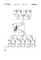
- FIG. 1is a simplified block diagram showing a wireless two-way messaging system incorporating a particular embodiment of the invention.
- base transceivers 101 and 102are connected via information channel wirelines 103 and 104, and control wirelines 105 and 106 to regional control processor (“RCP") 107, and RCP 107 is connected to satellite hub 108 via wireline 109.
- RCPregional control processor
- Each base transceiveris adapted to receive, transmit and process radio signals having a fixed channel bandwidth B.
- Network Gateway Controller (“NGC”) 110is shown to be connected to satellite hub 111 by wireline 112, and to application host/database (“AH/D”) 113 by wireline 114.
- NTCNetwork Gateway Controller
- the communication link provided by satellite hubs 108 and 111 and direct broadcast satellite 115is referred to as the backbone message transport ("BMT") link.
- Field transceivers 116 and 134are shown to be located in the vicinity of base transceiver 101.
- Field transceiver 116is adapted to transmit and receive encoded radio signals having a fixed channel bandwidth B. A portion of this bandwidth, designated I, is employed to carry information, and the remainder of bandwidth B, designated E, is used to provide error correction for the information portion of the signal. Typically, forward error correction would be employed, but other coding schemes could also be used.
- a transmission form end to endwould involve a minimum of six nodes (a field transceiver, a base transceiver, an RCP, a BMT link, an NGC and an AH/D).
- nodesa field transceiver, a base transceiver, an RCP, a BMT link, an NGC and an AH/D.
- field transceiver 116initiates a request to receive data from AH/D 113 by transmitting an encoded radio signal of bandwidth B.
- a requestwould include information as to the identity of the field transceiver and the particular data and AH/D being queried.
- field transceiver 116includes radio transmitter/receiver ("T/R") 117, controller 118, memory 119, and interface 120. Since this is an initial transmission, controller 118 would instruct transmit/receive unit 118 to employ a predetermined portion of bandwidth B for the purposes of error correction (the predetermined portion, designated El, would be set as a function of information retrieved by controller 118 from memory 119).
- the encoded signal(containing information of bandwidth B-E 1 , and error correction of bandwidth E 1 ) would then be transmitted from T/R 117 for reception by a base transceiver.
- the signal transmitted by field transceiver 116is received and processed by base transceiver 101.
- controller 122 within base transceiver 101performs a qualitative assessment of the signal. If it is determined that present transmission environment requires a level of error correction higher than that afforded by bandwidth E l (i.e., radio channel quality is poor), or if an information reduction ("IR") signal is received from RCP 107, a message instructing field transceiver 116 to increase the error correction bandwidth to an appropriate level is generated by controller 122 and transmitted by base transceiver 101.
- IRinformation reduction
- Controller 118 of field transceiver 116responds by increasing the bandwidth devoted to error correction to some value E 1+ (where E 1+ >E 1 ), and re-transmits the previously transmitted information at a reduced bandwidth of B-E 1+ . All communications between field transceiver 116 and base transceiver 101 will be carried out at this increased error correction level until an assessment of the signal received at base transceiver 101 indicates that a different level of error correction (either higher or lower) is merited.
- controller 122If, however, the assessment of the initial signal received from field transceiver 116 indicates that the present transmission environment would tolerate signals with a lesser degree of error correction controller 122 generates a message instructing field transceiver 116 to decrease the error correction bandwidth to a value of E 1- (where E 1- ⁇ E 1 ). This message is then transmitted to field transceiver 116 by base transceiver 101; although transmission of this message may be prohibited if controller 122 receives an IR signal from RCP 107 via control wireline 105.
- the rate at which base transceiver 101 receives field transceiver 116's request for data from AH/D 113varies.
- the rate at which data travels from base transceiver 101 to RCP 107 along information channel wireline 103fluctuates.
- the data received by RCP 107 on information channel wireline 103is passed to wireline 109 and the BMT link (which includes satellite 115, and satellite hubs 108 and 111).
- RCP 107functions to provide an intelligent buffer between the fluctuating rate data arriving on information channel wireline 103 and the fixed data rate of the BMT link.
- RCP 107also embeds information reflecting the aggregate rate at which data is being collected from base transceivers, and the fullness of buffer 125, into the data stream transmitted along wireline 109.
- RCP 107includes controller 123, and buffers 124 and 125.
- Controller 123functions to monitor the rate at which data is being sent to and from the various base transceivers connected to buffer 124, as well as the rate at which data is being sent to buffer 125 from the BMT link.
- controller 123receives information from controller 122 regarding the rate at which data from base transceiver 101 will be sent to buffer 124. If controller 123 determines that the aggregate incoming data rate to buffer 124 is equal to the fixed rate at which data may be passed through the BMT link, the incoming data is multiplexed or packetized within RCP 107, and then passed to satellite hub 108 via wireline 109.
- controller 123determines that the aggregate incoming data rate to buffer 124 is less than the fixed data rate of the BMT link, RCP 107 will effectively elevate the data rate by adding bits to the data stream before it is transmitted along wireline 109. These additional bits are inserted in a way that will not affect the information carded by the data stream (a practice commonly referred to as "bit stuffing"). Contrastingly, if controller 123 determines that the aggregate incoming data rate to buffer 124 is in excess of the maximum BMT link data rate, the incoming data will be stored in buffer 124 as it arrives, and allowed to pass through to wireline 109 at a rate equal to the maximum BMT link data rate.
- controller 123determines that buffer 124 is in danger of becoming full (a condition that would result in the loss of any data subsequently transmitted to RCP 107 from base transceivers), it sends an IR signal to base transceiver or transceivers currently transmitting information to RCP 107 (in this case, base transceiver 101).
- This IR signalcauses controller 122 within the base transceiver 101 to increase the bandwidth being used for error correction in communicating with field transceiver 116, thereby reducing the information bandwidth. This effectively diminishes the rate at which base transceiver 101 will transfer information to buffer 124, and allows for that buffer to be emptied.
- controller 123determines that buffer 124 is no longer in danger of becoming full, it will discontinue the IR signal being transmitted to base transceiver 101. Controller 122 will then be free to reduce the bandwidth devoted to error correction to a level suitable for the transmission environment.
- the signal from RCP 107(which includes information as to the identity of field transceiver 116 and the particular data and AH/D being queried, as well as information reflecting the aggregate rate at which data is being collected by RCP 107, and the fullness of buffer 125) arrives at NGC 110 via wireline 112.
- NGC 110depacketizes or demultiplexes the received signal, depending upon the encoding method employed by RCP 107, and routes the information contained in the signal to buffer 126.
- Controller 127retrieves information relating to the identity of field transceiver 116 and AH/D 113 (the particular AH/D being queried) from the buffered signal and compares it to a listing of approved subscribers stored in database 128. If field transceiver 116 is found to be a subscriber approved to receive information from AH/D 113, controller 127 allows the request for information to be passed from buffer 126 to AH/D 113 at a fixed rate via wireline 114. This fixed rate is set by controller 127 as a function of stored information retrieved from database 128. Database 128 contains information regarding the particular data transmission capabilities of any and all AH/Ds connected to NGC 110.
- Controller 129 within AH/D 113in response to the received request, retrieves the needed information from database 130, and transmits it at a fixed rate to buffer 131 via wireline 114. Controller 129 also embeds information as to the identity of the intended recipient of the information (field transmitter 116) into the data stream transmitted along wireline 114.
- Controller 127transfers the data received by buffer 131 to the link BMT via wireline 112. This data transfer must take place at the fixed rate required by the BMT link. As this fixed BMT rate is not necessarily equal to the rate at which AH/D 113 transfers data, buffer 131 is needed. If controller 127 determines that the incoming data rate to buffer 131 is less than the fixed data rate of the BMT link, NGC 110 will elevate the data rate by bit stuffing. Controller 127 may pause before allowing the data stored in buffer 131 to be transferred to the BMT link. This pause would be entered into if controller 127 had received a message indicating that buffer 125 of RCP 107 was nearly full (such information was included in the data requesting signal received from RCP 107). The pause may be for a fixed period or until controller 127 receives information from RCP 107 that buffer 125 was no longer in danger of becoming full. In any case, the data is transferred from the BMT link to buffer 125 via wireline 109.
- controller 123Upon receipt of the data intended for field transceiver 117 being stored in buffer 125, controller 123 causes it to be transferred along information channel wireline 103 to base transceiver 101.
- the rate at which the data is transferred to base transceiver 101is equal to the rate at which data was last received by RCP 107 from base transceiver 101. This data rate is commensurate with the error correction/information bandwidth ratio employed by field transceiver 116 in making the request for data.
- a signal carrying the requested informationmay be readily transmitted back to transceiver 116 employing the same error correction/information bandwidth ratio--A level of error correction suitable for the present transmission environment and overall system data load.
- field transceiver 116was transmitting in an area serviced by base transceiver 101.
- signals transmitted to and from a field transceivermay be received by different base transceivers (such as base transceiver 102) depending upon the location of a field transceiver.
- Base transceiver 102which operates in manner similar to that of base transceiver 101, is shown in FIG. 1 to include controller 132 and T/R 133.
- the reception and passing of a received signal among various base transceiverscan be managed in a fashion similar to that of a cellular telephone signal being passed from cell to cell.
- RCP 107may simultaneously receive more than one signal originating from more than one field transceiver, or receive more than one signal from the BMT link intended for more than one field transceiver. This additional information flowing through the system merely adds to the aggregate information flow and is compensated for through the buffering and information reduction processes described above.
- FIG. 2is a simplified block diagram showing a second wireless two-way messaging system incorporating components similar to those shown in FIG. 1.
- the systemincludes BMT 201 which is linked by wirelines 202, 203, 204 and 205 to RCPs 205, 206 and 207.
- Each of the RCPsis shown to be linked by control and information channel wirelines to two base transceivers, which are numbered 208 through 213.
- BMT 201is also shown to be linked by wirelines 214, 215 and 216 to NGCs 217 and 218. Each of these NGCs is linked by wireline to two AD/Hs, numbered 219 through 222.
- AD/Hsnumbered 219 through 222.
- communicationsare carried out between the base transceivers and various field transceivers (not shown).
- the field transceiversexchange information with the AH/Ds via radio transmissions, wirelines, base transceivers, NGCs and a BMT in a manner similar to that described for the system of FIG. 1.
- wirelines 223 and 224connect all of the RCPs within the system together, thereby allowing the controllers within each of the RCPs to share information regarding the present level at which each is allowing data to be passed to wireline 202 for transmission to BMT 201.
- the aggregate data rate flowing along wireline 202can be kept to a level matching the fixed data rate of BMT 201.
- the buffers within each of RCPsemploy variable buffering to allow the rate of data exiting each RCP to be varied somewhat independently of the rate at which data is received by a given RCP from any associated base transceivers (the buffering is performed in a manner similar to that described for RCP 107 of FIG. 1).
- Control wireline 225provides a link between NGC 217 and NGC 218. This link allows the controllers within the NGCs to share information regarding the level at which each is allowing data to be passed to BMT 210 via wireline 214. Each of the NGCs can then determine the aggregate rate at which dam is flowing along wireline 214. By utilizing the buffers contained within each NGC, the controllers can regulate this aggregate data flow to matching the fixed data rate of BMT 201 (this inter-NGC buffering is performed in a manner similar to the buffering described for RCP 107 of FIG. 1). The inter-NGC buffering is performed in addition to the any other buffering or information reduction processes normally carried out within an NGC (such as those described above for NGC 110 of FIG. 1).
- the above-described inventionprovides a practical technique for effecting variable error-correction wireless communications within a communication system, wherein the bandwidth dedicated to wireless signal error correction is varied in response to fading within the transmission environment, and the rate at which information is accumulating within the nodes of the communication system. It will be understood that the particular methods described are only illustrative of the principles of the present invention, and that various modifications could be made by those skilled in the an without departing from the scope and spirit of the present invention, which is limited only by the claims that follow. One such modification would include applying the method of this invention to a systems employing a wireline BMT link.
Landscapes
- Engineering & Computer Science (AREA)
- Quality & Reliability (AREA)
- Computer Networks & Wireless Communication (AREA)
- Signal Processing (AREA)
- Physics & Mathematics (AREA)
- Astronomy & Astrophysics (AREA)
- Aviation & Aerospace Engineering (AREA)
- General Physics & Mathematics (AREA)
- Mobile Radio Communication Systems (AREA)
- Detection And Prevention Of Errors In Transmission (AREA)
- Communication Control (AREA)
- Radio Relay Systems (AREA)
Abstract
Description
Claims (12)
Priority Applications (5)
| Application Number | Priority Date | Filing Date | Title |
|---|---|---|---|
| US08/146,372US5590405A (en) | 1993-10-29 | 1993-10-29 | Communication technique employing variable information transmission |
| CA002128386ACA2128386C (en) | 1993-10-29 | 1994-07-20 | Communication technique employing variable information transmission |
| EP94307657AEP0651531B1 (en) | 1993-10-29 | 1994-10-19 | Communication technique employing variable information transmission rate function of quality |
| DE69433834TDE69433834T2 (en) | 1993-10-29 | 1994-10-19 | Communication method with the quality according to variable data transmission rate |
| JP28722594AJP3342591B2 (en) | 1993-10-29 | 1994-10-28 | Information transmission method of communication system |
Applications Claiming Priority (1)
| Application Number | Priority Date | Filing Date | Title |
|---|---|---|---|
| US08/146,372US5590405A (en) | 1993-10-29 | 1993-10-29 | Communication technique employing variable information transmission |
Publications (1)
| Publication Number | Publication Date |
|---|---|
| US5590405Atrue US5590405A (en) | 1996-12-31 |
Family
ID=22517083
Family Applications (1)
| Application Number | Title | Priority Date | Filing Date |
|---|---|---|---|
| US08/146,372Expired - LifetimeUS5590405A (en) | 1993-10-29 | 1993-10-29 | Communication technique employing variable information transmission |
Country Status (5)
| Country | Link |
|---|---|
| US (1) | US5590405A (en) |
| EP (1) | EP0651531B1 (en) |
| JP (1) | JP3342591B2 (en) |
| CA (1) | CA2128386C (en) |
| DE (1) | DE69433834T2 (en) |
Cited By (21)
| Publication number | Priority date | Publication date | Assignee | Title |
|---|---|---|---|---|
| US5761223A (en)* | 1994-07-21 | 1998-06-02 | Matsushita Electric Industrial Co., Ltd. | Error correcting device |
| FR2759234A1 (en)* | 1997-01-31 | 1998-08-07 | Canon Kk | Data transmission system for sending facsimile image data at maximum speed |
| FR2759235A1 (en)* | 1997-01-31 | 1998-08-07 | Canon Kk | Facsimile-copier data system for rapid facsimile transmission |
| FR2759223A1 (en)* | 1997-01-31 | 1998-08-07 | Canon Kk | Data transmission system for facsimile copy image data |
| FR2759225A1 (en)* | 1997-01-31 | 1998-08-07 | Canon Kk | Symbol circulation device especially for facsimile |
| US5940769A (en)* | 1995-03-30 | 1999-08-17 | Kabushiki Kaisha Toshiba | Radio communication system having re-send control method |
| US5995515A (en)* | 1994-06-20 | 1999-11-30 | Sony Corporation | Communication system, base station, mobile station, and radio communication system |
| US6067445A (en)* | 1994-10-21 | 2000-05-23 | Seiko Communications Systems Inc. | Dual channel dual speed FM subcarrier paging system |
| US6134230A (en)* | 1997-08-29 | 2000-10-17 | Telefonaktiebolaget Lm Ericsson | Method for selecting a link protocol for a transparent data service in a digital communications system |
| US6216244B1 (en) | 1998-10-07 | 2001-04-10 | Cisco Systems, Inc. | Point-to-multipoint variable antenna compensation system |
| US6320850B1 (en) | 1998-04-24 | 2001-11-20 | Trw Inc. | Satellite communication adaptive control coding |
| US6385456B2 (en)* | 1996-01-04 | 2002-05-07 | Sony Corporation | Method and system of transmitting data in a cellular radio system |
| US6421541B1 (en)* | 1999-01-22 | 2002-07-16 | Telefonaktiebolaget Lm Ericsson | Adaptable bandwidth |
| US20020101913A1 (en)* | 1999-07-28 | 2002-08-01 | Masters Jeffrey Tony | Dynamic adaptive modulation negotiation for point-to-point terrestrial links |
| US20030050073A1 (en)* | 2001-08-31 | 2003-03-13 | Stephen Wasko | Control of network element supporting variable transmission modes |
| US6714794B1 (en)* | 2000-10-30 | 2004-03-30 | Motorola, Inc. | Communication system for wireless communication of content to users |
| US20040185889A1 (en)* | 2001-06-29 | 2004-09-23 | Shipman Robert A. | Method and apparatus for routing data |
| US20040218528A1 (en)* | 2001-06-29 | 2004-11-04 | Shipman Robert A | Method and apparatus for routing data with support for changing mobility requirements |
| US20070120950A1 (en)* | 1998-08-07 | 2007-05-31 | Matti Jokimies | Method and apparatus for controlling encoding of a digital video signal according to monitored parameters of a radio frequency communication signal |
| US20100124922A1 (en)* | 2008-11-19 | 2010-05-20 | Palmer John R | Satellite transmission obfuscation |
| US8255569B1 (en)* | 2000-02-22 | 2012-08-28 | Microsoft Corporation | Methods and systems for compressing data packets |
Families Citing this family (53)
| Publication number | Priority date | Publication date | Assignee | Title |
|---|---|---|---|---|
| US6334219B1 (en) | 1994-09-26 | 2001-12-25 | Adc Telecommunications Inc. | Channel selection for a hybrid fiber coax network |
| US5974106A (en)* | 1995-09-01 | 1999-10-26 | Motorola, Inc. | Method and apparatus for multirate data communications |
| GB2306867B (en)* | 1995-10-26 | 1998-06-03 | Bosch Gmbh Robert | Method of optimizing the transmission of signals |
| FI955944A7 (en)* | 1995-12-11 | 1997-06-12 | Nokia Telecommunications Oy | Speed matching method and speed adapter |
| FI100567B (en) | 1996-01-08 | 1997-12-31 | Nokia Telecommunications Oy | Power adapter and data transmission procedure in mobile telephone networks |
| DE69704862T2 (en)* | 1996-06-13 | 2001-08-30 | Nortel Networks Ltd., Montreal | SPACIOUS CORDLESS DISTRIBUTION SYSTEM |
| US5812968A (en)* | 1996-08-28 | 1998-09-22 | Ericsson, Inc. | Vocoder apparatus using the link margin |
| FI116181B (en)* | 1997-02-07 | 2005-09-30 | Nokia Corp | Information coding method utilizing error correction and error identification and devices |
| FI102866B (en)* | 1997-04-09 | 1999-02-26 | Nokia Telecommunications Oy | Reduction of interference in mobile phone systems |
| JPH1168873A (en) | 1997-08-08 | 1999-03-09 | Nec Corp | Data communication method and data communication system |
| US6021268A (en)* | 1997-08-21 | 2000-02-01 | Analytical Graphics, Inc. | Method and apparatus for modeling receiver bandwidth for telecommunications analysis |
| JP3191760B2 (en) | 1998-03-02 | 2001-07-23 | 日本電気株式会社 | Digital wireless communication system, digital wireless communication method, and recording medium storing digital wireless communication method |
| FR2782429B1 (en)* | 1998-08-13 | 2000-10-06 | Alsthom Cge Alcatel | METHOD FOR CHANGING THE CODING LEVEL OF DIGITAL DATA TRANSMITTED BETWEEN A TRANSMITTER AND A RECEIVER AT A CONSTANT RATE |
| US6307487B1 (en) | 1998-09-23 | 2001-10-23 | Digital Fountain, Inc. | Information additive code generator and decoder for communication systems |
| US7068729B2 (en) | 2001-12-21 | 2006-06-27 | Digital Fountain, Inc. | Multi-stage code generator and decoder for communication systems |
| US6134548A (en)* | 1998-11-19 | 2000-10-17 | Ac Properties B.V. | System, method and article of manufacture for advanced mobile bargain shopping |
| EP1173822A1 (en)* | 1998-11-12 | 2002-01-23 | AC Properties B.V. | A system, method and article of manufacture for advanced mobile bargain shopping |
| US6512749B1 (en)* | 1999-09-29 | 2003-01-28 | Trw Inc. | Downlink transmission and reception techniques for a processing communication satellite |
| US6473597B1 (en) | 2000-04-12 | 2002-10-29 | Thomas M. Johnson | Method and apparatus for modeling transmitter bandwidth for telecommunications analysis |
| US7009949B1 (en)* | 2000-11-17 | 2006-03-07 | Lucent Technologies Inc. | Asymmetric rate feedback and adjustment system for wireless communications |
| DE60113728T2 (en)* | 2001-01-29 | 2006-06-29 | Koninklijke Philips Electronics N.V. | SATELLITE COMMUNICATION SYSTEM WITH VARIABLE DATA RATE ON MULTIPLE VEHICLES |
| JP3769468B2 (en) | 2001-03-21 | 2006-04-26 | 株式会社エヌ・ティ・ティ・ドコモ | Communication quality control method, communication quality control system, packet analysis device, and data transmission terminal device |
| SE0102849D0 (en)* | 2001-08-22 | 2001-08-22 | Ericsson Telefon Ab L M | Methods and arrangements in a telecommunicaton system |
| GB2384394A (en)* | 2002-01-18 | 2003-07-23 | Inmarsat Ltd | Adapting transmission parameters to link conditions |
| US9240810B2 (en) | 2002-06-11 | 2016-01-19 | Digital Fountain, Inc. | Systems and processes for decoding chain reaction codes through inactivation |
| US8121536B2 (en) | 2002-07-23 | 2012-02-21 | Qualcomm Incorporated | Noise compensation in satellite communications |
| EP2357732B1 (en) | 2002-10-05 | 2022-04-06 | QUALCOMM Incorporated | Systematic encoding and decoding of chain reaction codes |
| EP2722995B1 (en) | 2003-10-06 | 2023-04-19 | QUALCOMM Incorporated | Soft-Decision Decoding of Multi-Stage Chain Reaction Codes |
| US7418651B2 (en) | 2004-05-07 | 2008-08-26 | Digital Fountain, Inc. | File download and streaming system |
| KR101292851B1 (en) | 2006-02-13 | 2013-08-02 | 디지털 파운튼, 인크. | Streaming and buffering using variable fec overhead and protection periods |
| US9270414B2 (en) | 2006-02-21 | 2016-02-23 | Digital Fountain, Inc. | Multiple-field based code generator and decoder for communications systems |
| US20070220403A1 (en)* | 2006-02-27 | 2007-09-20 | Honeywell International Inc. | System and method for dynamic allocation of forward error encoding |
| WO2007134196A2 (en) | 2006-05-10 | 2007-11-22 | Digital Fountain, Inc. | Code generator and decoder using hybrid codes |
| US9380096B2 (en) | 2006-06-09 | 2016-06-28 | Qualcomm Incorporated | Enhanced block-request streaming system for handling low-latency streaming |
| US9432433B2 (en) | 2006-06-09 | 2016-08-30 | Qualcomm Incorporated | Enhanced block-request streaming system using signaling or block creation |
| US9386064B2 (en) | 2006-06-09 | 2016-07-05 | Qualcomm Incorporated | Enhanced block-request streaming using URL templates and construction rules |
| US9178535B2 (en) | 2006-06-09 | 2015-11-03 | Digital Fountain, Inc. | Dynamic stream interleaving and sub-stream based delivery |
| US9209934B2 (en) | 2006-06-09 | 2015-12-08 | Qualcomm Incorporated | Enhanced block-request streaming using cooperative parallel HTTP and forward error correction |
| US9419749B2 (en) | 2009-08-19 | 2016-08-16 | Qualcomm Incorporated | Methods and apparatus employing FEC codes with permanent inactivation of symbols for encoding and decoding processes |
| US9237101B2 (en) | 2007-09-12 | 2016-01-12 | Digital Fountain, Inc. | Generating and communicating source identification information to enable reliable communications |
| US9281847B2 (en) | 2009-02-27 | 2016-03-08 | Qualcomm Incorporated | Mobile reception of digital video broadcasting—terrestrial services |
| US9288010B2 (en) | 2009-08-19 | 2016-03-15 | Qualcomm Incorporated | Universal file delivery methods for providing unequal error protection and bundled file delivery services |
| US9917874B2 (en) | 2009-09-22 | 2018-03-13 | Qualcomm Incorporated | Enhanced block-request streaming using block partitioning or request controls for improved client-side handling |
| US9049497B2 (en) | 2010-06-29 | 2015-06-02 | Qualcomm Incorporated | Signaling random access points for streaming video data |
| US8918533B2 (en) | 2010-07-13 | 2014-12-23 | Qualcomm Incorporated | Video switching for streaming video data |
| US9185439B2 (en) | 2010-07-15 | 2015-11-10 | Qualcomm Incorporated | Signaling data for multiplexing video components |
| US9596447B2 (en) | 2010-07-21 | 2017-03-14 | Qualcomm Incorporated | Providing frame packing type information for video coding |
| US8806050B2 (en) | 2010-08-10 | 2014-08-12 | Qualcomm Incorporated | Manifest file updates for network streaming of coded multimedia data |
| US8958375B2 (en) | 2011-02-11 | 2015-02-17 | Qualcomm Incorporated | Framing for an improved radio link protocol including FEC |
| US9270299B2 (en) | 2011-02-11 | 2016-02-23 | Qualcomm Incorporated | Encoding and decoding using elastic codes with flexible source block mapping |
| US9253233B2 (en) | 2011-08-31 | 2016-02-02 | Qualcomm Incorporated | Switch signaling methods providing improved switching between representations for adaptive HTTP streaming |
| US9843844B2 (en) | 2011-10-05 | 2017-12-12 | Qualcomm Incorporated | Network streaming of media data |
| US9294226B2 (en) | 2012-03-26 | 2016-03-22 | Qualcomm Incorporated | Universal object delivery and template-based file delivery |
Citations (10)
| Publication number | Priority date | Publication date | Assignee | Title |
|---|---|---|---|---|
| US4825193A (en)* | 1988-01-07 | 1989-04-25 | Motorola, Inc. | Acknowledge back pager with adaptive variable transmitter output power |
| US4833701A (en)* | 1988-01-27 | 1989-05-23 | Motorola, Inc. | Trunked communication system with nationwide roaming capability |
| US4868560A (en)* | 1988-04-14 | 1989-09-19 | Motorola, Inc. | Voice paging system providing deferred paging capability |
| US4928096A (en)* | 1987-11-16 | 1990-05-22 | Motorola, Inc. | Paging terminal apparatus with message storage and retransmission capability and method therefor |
| US5010317A (en)* | 1989-11-30 | 1991-04-23 | Motorola, Inc. | Satellite based simulcast paging system |
| US5070536A (en)* | 1988-08-04 | 1991-12-03 | Norand Corporation | Mobile radio data communication system and method |
| US5142533A (en)* | 1991-03-28 | 1992-08-25 | Motorola, Inc. | Method for controlling the scheduling of multiple access to communication resources |
| US5313467A (en)* | 1989-11-15 | 1994-05-17 | Digital Equipment Corporation | Integrated communication link having a dynamically allocatable bandwidth and protocol for transmission of allocation information over the link |
| US5321541A (en)* | 1991-12-12 | 1994-06-14 | At&T Bell Laboratories | Passive optical communication network with broadband upgrade |
| US5361399A (en)* | 1992-06-02 | 1994-11-01 | Pagemart, Inc. | Adaptive communication system for transmitting between base stations and portable transceivers via different data rate communication links |
Family Cites Families (2)
| Publication number | Priority date | Publication date | Assignee | Title |
|---|---|---|---|---|
| JPS5758447A (en)* | 1980-09-25 | 1982-04-08 | Oki Electric Ind Co Ltd | Relay device |
| JPH0626343B2 (en)* | 1988-12-16 | 1994-04-06 | 日本電気株式会社 | Modulator / demodulator data transmission rate automatic switching system |
- 1993
- 1993-10-29USUS08/146,372patent/US5590405A/ennot_activeExpired - Lifetime
- 1994
- 1994-07-20CACA002128386Apatent/CA2128386C/ennot_activeExpired - Fee Related
- 1994-10-19DEDE69433834Tpatent/DE69433834T2/ennot_activeExpired - Lifetime
- 1994-10-19EPEP94307657Apatent/EP0651531B1/ennot_activeExpired - Lifetime
- 1994-10-28JPJP28722594Apatent/JP3342591B2/ennot_activeExpired - Fee Related
Patent Citations (10)
| Publication number | Priority date | Publication date | Assignee | Title |
|---|---|---|---|---|
| US4928096A (en)* | 1987-11-16 | 1990-05-22 | Motorola, Inc. | Paging terminal apparatus with message storage and retransmission capability and method therefor |
| US4825193A (en)* | 1988-01-07 | 1989-04-25 | Motorola, Inc. | Acknowledge back pager with adaptive variable transmitter output power |
| US4833701A (en)* | 1988-01-27 | 1989-05-23 | Motorola, Inc. | Trunked communication system with nationwide roaming capability |
| US4868560A (en)* | 1988-04-14 | 1989-09-19 | Motorola, Inc. | Voice paging system providing deferred paging capability |
| US5070536A (en)* | 1988-08-04 | 1991-12-03 | Norand Corporation | Mobile radio data communication system and method |
| US5313467A (en)* | 1989-11-15 | 1994-05-17 | Digital Equipment Corporation | Integrated communication link having a dynamically allocatable bandwidth and protocol for transmission of allocation information over the link |
| US5010317A (en)* | 1989-11-30 | 1991-04-23 | Motorola, Inc. | Satellite based simulcast paging system |
| US5142533A (en)* | 1991-03-28 | 1992-08-25 | Motorola, Inc. | Method for controlling the scheduling of multiple access to communication resources |
| US5321541A (en)* | 1991-12-12 | 1994-06-14 | At&T Bell Laboratories | Passive optical communication network with broadband upgrade |
| US5361399A (en)* | 1992-06-02 | 1994-11-01 | Pagemart, Inc. | Adaptive communication system for transmitting between base stations and portable transceivers via different data rate communication links |
Cited By (26)
| Publication number | Priority date | Publication date | Assignee | Title |
|---|---|---|---|---|
| US5995515A (en)* | 1994-06-20 | 1999-11-30 | Sony Corporation | Communication system, base station, mobile station, and radio communication system |
| US5761223A (en)* | 1994-07-21 | 1998-06-02 | Matsushita Electric Industrial Co., Ltd. | Error correcting device |
| US6067445A (en)* | 1994-10-21 | 2000-05-23 | Seiko Communications Systems Inc. | Dual channel dual speed FM subcarrier paging system |
| US5940769A (en)* | 1995-03-30 | 1999-08-17 | Kabushiki Kaisha Toshiba | Radio communication system having re-send control method |
| US6385456B2 (en)* | 1996-01-04 | 2002-05-07 | Sony Corporation | Method and system of transmitting data in a cellular radio system |
| FR2759223A1 (en)* | 1997-01-31 | 1998-08-07 | Canon Kk | Data transmission system for facsimile copy image data |
| FR2759225A1 (en)* | 1997-01-31 | 1998-08-07 | Canon Kk | Symbol circulation device especially for facsimile |
| FR2759235A1 (en)* | 1997-01-31 | 1998-08-07 | Canon Kk | Facsimile-copier data system for rapid facsimile transmission |
| FR2759234A1 (en)* | 1997-01-31 | 1998-08-07 | Canon Kk | Data transmission system for sending facsimile image data at maximum speed |
| US6134230A (en)* | 1997-08-29 | 2000-10-17 | Telefonaktiebolaget Lm Ericsson | Method for selecting a link protocol for a transparent data service in a digital communications system |
| US6320850B1 (en) | 1998-04-24 | 2001-11-20 | Trw Inc. | Satellite communication adaptive control coding |
| US20070120950A1 (en)* | 1998-08-07 | 2007-05-31 | Matti Jokimies | Method and apparatus for controlling encoding of a digital video signal according to monitored parameters of a radio frequency communication signal |
| US7764927B2 (en) | 1998-08-07 | 2010-07-27 | Nokia Corporation | Method and apparatus for controlling encoding of a digital video signal according to monitored parameters of a radio frequency communication signal |
| US6216244B1 (en) | 1998-10-07 | 2001-04-10 | Cisco Systems, Inc. | Point-to-multipoint variable antenna compensation system |
| US6421541B1 (en)* | 1999-01-22 | 2002-07-16 | Telefonaktiebolaget Lm Ericsson | Adaptable bandwidth |
| US20020101913A1 (en)* | 1999-07-28 | 2002-08-01 | Masters Jeffrey Tony | Dynamic adaptive modulation negotiation for point-to-point terrestrial links |
| US8255569B1 (en)* | 2000-02-22 | 2012-08-28 | Microsoft Corporation | Methods and systems for compressing data packets |
| US6714794B1 (en)* | 2000-10-30 | 2004-03-30 | Motorola, Inc. | Communication system for wireless communication of content to users |
| US20040185889A1 (en)* | 2001-06-29 | 2004-09-23 | Shipman Robert A. | Method and apparatus for routing data |
| US20040218528A1 (en)* | 2001-06-29 | 2004-11-04 | Shipman Robert A | Method and apparatus for routing data with support for changing mobility requirements |
| US7346015B2 (en)* | 2001-06-29 | 2008-03-18 | British Telecommunications Public Limited Company | Method and apparatus for routing data with support for changing mobility requirements |
| US7359358B2 (en) | 2001-06-29 | 2008-04-15 | British Telecommunications Public Limited Company | Method and apparatus for routing data |
| US7079846B2 (en)* | 2001-08-31 | 2006-07-18 | Nokia Corporation | Control of network element supporting variable transmission modes |
| US20030050073A1 (en)* | 2001-08-31 | 2003-03-13 | Stephen Wasko | Control of network element supporting variable transmission modes |
| US20100124922A1 (en)* | 2008-11-19 | 2010-05-20 | Palmer John R | Satellite transmission obfuscation |
| US8447295B2 (en)* | 2008-11-19 | 2013-05-21 | The Boeing Company | System and method for obfuscating satellite terminal transmission activity |
Also Published As
| Publication number | Publication date |
|---|---|
| JP3342591B2 (en) | 2002-11-11 |
| EP0651531B1 (en) | 2004-06-09 |
| DE69433834T2 (en) | 2006-07-06 |
| CA2128386C (en) | 1999-04-13 |
| DE69433834D1 (en) | 2004-07-15 |
| EP0651531A2 (en) | 1995-05-03 |
| JPH07183873A (en) | 1995-07-21 |
| CA2128386A1 (en) | 1995-04-30 |
| EP0651531A3 (en) | 1998-01-28 |
Similar Documents
| Publication | Publication Date | Title |
|---|---|---|
| US5590405A (en) | Communication technique employing variable information transmission | |
| US5754555A (en) | Subscriber network arrangement for connecting subscribers to a telephone network | |
| US6300881B1 (en) | Data transfer system and method for communicating utility consumption data over power line carriers | |
| JP2895460B2 (en) | Satellite / wireless telephone mobile system | |
| US6421374B2 (en) | Method for providing service and rate negotiation in a mobile communication system | |
| US5526376A (en) | Intelligent repeater interface | |
| JP4299613B2 (en) | Mobile communication subscriber unit and method for communicating with wireless variable bandwidth air link unit | |
| US7801545B2 (en) | Power control method of discontinuous transmission | |
| US6122291A (en) | Communication system and operating method thereof | |
| AU730799B2 (en) | Satellite communications system with dual mode bandwidth control | |
| EP0840533B1 (en) | A method and system for communicating with remote units in a communication system | |
| EP1164805B1 (en) | Method for controlling transmission capacity and mobile communication system | |
| NO973655L (en) | Speed adjustment in a non-uniform, non-transparent data channel | |
| JP2000516063A (en) | Method and apparatus for enabling mobile to mobile calls in a communication system | |
| US20230043514A1 (en) | Method for providing continuous connectivity to a device | |
| US20030087651A1 (en) | Method of and apparatus for implementing adaptive downstream modulation in a fixed wireless communication system | |
| US6021120A (en) | System and method for creating full duplex virtual circuits based on multiple asymmetrical links | |
| JP2006174263A (en) | Multi-hop wireless network | |
| US5691982A (en) | Method for transferring data transmitted from base stations to a paging area controller in a personal paging network | |
| JP2010114904A (en) | Multi-hop wireless network | |
| KR20030033436A (en) | Method of controling data transmission rate of satellite communication | |
| WO2001031813A1 (en) | Access request in a satellite communication system | |
| MXPA99003798A (en) | Dual mode symmetric/asymmetric communication control system | |
| JP2003087351A (en) | Mobile communication control device and mobile communication control method | |
| JPH01206735A (en) | Radio communication system |
Legal Events
| Date | Code | Title | Description |
|---|---|---|---|
| AS | Assignment | Owner name:AMERICAN TELEPHONE AND TELEGRAPH COMPANY, NEW YORK Free format text:ASSIGNMENT OF ASSIGNORS INTEREST;ASSIGNORS:DALY, JOHN J.;HAISCH, HERMAN F.;KAPSALES, PETER;AND OTHERS;REEL/FRAME:006762/0368;SIGNING DATES FROM 19931027 TO 19931028 | |
| AS | Assignment | Owner name:AT&T CORP., NEW YORK Free format text:ASSIGNMENT OF ASSIGNORS INTEREST;ASSIGNOR:AMERICAN TELELPHONE AND TELEGRAPH COMPANY;REEL/FRAME:007527/0274 Effective date:19940420 Owner name:AT&T IPM CORP., FLORIDA Free format text:ASSIGNMENT OF ASSIGNORS INTEREST;ASSIGNOR:AT&T CORP.;REEL/FRAME:007528/0038 Effective date:19950523 | |
| AS | Assignment | Owner name:LUCENT TECHNOLOGIES, INC., NEW JERSEY Free format text:ASSIGNMENT OF ASSIGNORS INTEREST;ASSIGNOR:AT&T CORP.;REEL/FRAME:008102/0142 Effective date:19960329 | |
| STCF | Information on status: patent grant | Free format text:PATENTED CASE | |
| FEPP | Fee payment procedure | Free format text:PAYOR NUMBER ASSIGNED (ORIGINAL EVENT CODE: ASPN); ENTITY STATUS OF PATENT OWNER: LARGE ENTITY | |
| FPAY | Fee payment | Year of fee payment:4 | |
| AS | Assignment | Owner name:THE CHASE MANHATTAN BANK, AS COLLATERAL AGENT, TEX Free format text:CONDITIONAL ASSIGNMENT OF AND SECURITY INTEREST IN PATENT RIGHTS;ASSIGNOR:LUCENT TECHNOLOGIES INC. (DE CORPORATION);REEL/FRAME:011722/0048 Effective date:20010222 | |
| FEPP | Fee payment procedure | Free format text:PAYER NUMBER DE-ASSIGNED (ORIGINAL EVENT CODE: RMPN); ENTITY STATUS OF PATENT OWNER: LARGE ENTITY Free format text:PAYOR NUMBER ASSIGNED (ORIGINAL EVENT CODE: ASPN); ENTITY STATUS OF PATENT OWNER: LARGE ENTITY | |
| FPAY | Fee payment | Year of fee payment:8 | |
| AS | Assignment | Owner name:LUCENT TECHNOLOGIES INC., NEW JERSEY Free format text:TERMINATION AND RELEASE OF SECURITY INTEREST IN PATENT RIGHTS;ASSIGNOR:JPMORGAN CHASE BANK, N.A. (FORMERLY KNOWN AS THE CHASE MANHATTAN BANK), AS ADMINISTRATIVE AGENT;REEL/FRAME:018584/0446 Effective date:20061130 | |
| FPAY | Fee payment | Year of fee payment:12 | |
| AS | Assignment | Owner name:CREDIT SUISSE AG, NEW YORK Free format text:SECURITY INTEREST;ASSIGNOR:ALCATEL-LUCENT USA INC.;REEL/FRAME:030510/0627 Effective date:20130130 | |
| AS | Assignment | Owner name:ALCATEL-LUCENT USA INC., NEW JERSEY Free format text:RELEASE BY SECURED PARTY;ASSIGNOR:CREDIT SUISSE AG;REEL/FRAME:033950/0001 Effective date:20140819 |