US5590032A - Self-synchronized drive circuit for a synchronous rectifier in a clamped-mode power converter - Google Patents
Self-synchronized drive circuit for a synchronous rectifier in a clamped-mode power converterDownload PDFInfo
- Publication number
- US5590032A US5590032AUS08/452,560US45256095AUS5590032AUS 5590032 AUS5590032 AUS 5590032AUS 45256095 AUS45256095 AUS 45256095AUS 5590032 AUS5590032 AUS 5590032A
- Authority
- US
- United States
- Prior art keywords
- winding
- drive
- power
- synchronous rectifier
- voltage
- Prior art date
- Legal status (The legal status is an assumption and is not a legal conclusion. Google has not performed a legal analysis and makes no representation as to the accuracy of the status listed.)
- Ceased
Links
- 230000001360synchronised effectEffects0.000titleclaimsabstractdescription84
- 238000004804windingMethods0.000claimsabstractdescription155
- 230000008878couplingEffects0.000claimsdescription12
- 238000010168coupling processMethods0.000claimsdescription12
- 238000005859coupling reactionMethods0.000claimsdescription12
- 238000004146energy storageMethods0.000claims1
- 230000000737periodic effectEffects0.000abstractdescription4
- 239000003990capacitorSubstances0.000description5
- 230000001419dependent effectEffects0.000description3
- 238000010586diagramMethods0.000description3
- 230000009471actionEffects0.000description2
- 230000008859changeEffects0.000description2
- 238000002955isolationMethods0.000description2
- 230000003071parasitic effectEffects0.000description2
- UXUFTKZYJYGMGO-CMCWBKRRSA-N(2s,3s,4r,5r)-5-[6-amino-2-[2-[4-[3-(2-aminoethylamino)-3-oxopropyl]phenyl]ethylamino]purin-9-yl]-n-ethyl-3,4-dihydroxyoxolane-2-carboxamideChemical compoundO[C@@H]1[C@H](O)[C@@H](C(=O)NCC)O[C@H]1N1C2=NC(NCCC=3C=CC(CCC(=O)NCCN)=CC=3)=NC(N)=C2N=C1UXUFTKZYJYGMGO-CMCWBKRRSA-N0.000description1
- 238000006243chemical reactionMethods0.000description1
- 230000007812deficiencyEffects0.000description1
- 230000003993interactionEffects0.000description1
- 238000000034methodMethods0.000description1
- 230000008569processEffects0.000description1
- 230000004044responseEffects0.000description1
- 230000007704transitionEffects0.000description1
Images


Classifications
- H—ELECTRICITY
- H02—GENERATION; CONVERSION OR DISTRIBUTION OF ELECTRIC POWER
- H02M—APPARATUS FOR CONVERSION BETWEEN AC AND AC, BETWEEN AC AND DC, OR BETWEEN DC AND DC, AND FOR USE WITH MAINS OR SIMILAR POWER SUPPLY SYSTEMS; CONVERSION OF DC OR AC INPUT POWER INTO SURGE OUTPUT POWER; CONTROL OR REGULATION THEREOF
- H02M3/00—Conversion of DC power input into DC power output
- H02M3/22—Conversion of DC power input into DC power output with intermediate conversion into AC
- H02M3/24—Conversion of DC power input into DC power output with intermediate conversion into AC by static converters
- H02M3/28—Conversion of DC power input into DC power output with intermediate conversion into AC by static converters using discharge tubes with control electrode or semiconductor devices with control electrode to produce the intermediate AC
- H02M3/325—Conversion of DC power input into DC power output with intermediate conversion into AC by static converters using discharge tubes with control electrode or semiconductor devices with control electrode to produce the intermediate AC using devices of a triode or a transistor type requiring continuous application of a control signal
- H02M3/335—Conversion of DC power input into DC power output with intermediate conversion into AC by static converters using discharge tubes with control electrode or semiconductor devices with control electrode to produce the intermediate AC using devices of a triode or a transistor type requiring continuous application of a control signal using semiconductor devices only
- H02M3/33569—Conversion of DC power input into DC power output with intermediate conversion into AC by static converters using discharge tubes with control electrode or semiconductor devices with control electrode to produce the intermediate AC using devices of a triode or a transistor type requiring continuous application of a control signal using semiconductor devices only having several active switching elements
- H02M3/33576—Conversion of DC power input into DC power output with intermediate conversion into AC by static converters using discharge tubes with control electrode or semiconductor devices with control electrode to produce the intermediate AC using devices of a triode or a transistor type requiring continuous application of a control signal using semiconductor devices only having several active switching elements having at least one active switching element at the secondary side of an isolation transformer
- H02M3/33592—Conversion of DC power input into DC power output with intermediate conversion into AC by static converters using discharge tubes with control electrode or semiconductor devices with control electrode to produce the intermediate AC using devices of a triode or a transistor type requiring continuous application of a control signal using semiconductor devices only having several active switching elements having at least one active switching element at the secondary side of an isolation transformer having a synchronous rectifier circuit or a synchronous freewheeling circuit at the secondary side of an isolation transformer
- Y—GENERAL TAGGING OF NEW TECHNOLOGICAL DEVELOPMENTS; GENERAL TAGGING OF CROSS-SECTIONAL TECHNOLOGIES SPANNING OVER SEVERAL SECTIONS OF THE IPC; TECHNICAL SUBJECTS COVERED BY FORMER USPC CROSS-REFERENCE ART COLLECTIONS [XRACs] AND DIGESTS
- Y02—TECHNOLOGIES OR APPLICATIONS FOR MITIGATION OR ADAPTATION AGAINST CLIMATE CHANGE
- Y02B—CLIMATE CHANGE MITIGATION TECHNOLOGIES RELATED TO BUILDINGS, e.g. HOUSING, HOUSE APPLIANCES OR RELATED END-USER APPLICATIONS
- Y02B70/00—Technologies for an efficient end-user side electric power management and consumption
- Y02B70/10—Technologies improving the efficiency by using switched-mode power supplies [SMPS], i.e. efficient power electronics conversion e.g. power factor correction or reduction of losses in power supplies or efficient standby modes
- Y—GENERAL TAGGING OF NEW TECHNOLOGICAL DEVELOPMENTS; GENERAL TAGGING OF CROSS-SECTIONAL TECHNOLOGIES SPANNING OVER SEVERAL SECTIONS OF THE IPC; TECHNICAL SUBJECTS COVERED BY FORMER USPC CROSS-REFERENCE ART COLLECTIONS [XRACs] AND DIGESTS
- Y02—TECHNOLOGIES OR APPLICATIONS FOR MITIGATION OR ADAPTATION AGAINST CLIMATE CHANGE
- Y02E—REDUCTION OF GREENHOUSE GAS [GHG] EMISSIONS, RELATED TO ENERGY GENERATION, TRANSMISSION OR DISTRIBUTION
- Y02E10/00—Energy generation through renewable energy sources
- Y02E10/50—Photovoltaic [PV] energy
Definitions
- This inventionrelates to synchronous rectification and to a power converter employing synchronous rectification. It is particularly concerned with a self synchronized rectifier combined with a converter.
- a converteris a power processing circuit, that may have an input-output transformer isolation, that operates to convert an input voltage waveform with a DC component into an output DC voltage waveform.
- the presence of an isolation transformerrequires the use of a rectifier circuit in the converter output circuit to perform the waveform conversion.
- the traditional rectifieruses rectifying diodes that conduct the load current only when forward biased in response to the input waveform.
- some rectifiersi.e. synchronous rectifiers
- the diodesare replaced by controlled switches that are periodically biased into conduction and nonconduction in synchronism with the periodic waveform to be rectified.
- self-synchronized synchronous rectifiersthe biasing of the synchronous switches is supplied directly from a secondary winding of a transformer without requiring a separate drive to activate the synchronous switches.
- Self-synchronized synchronous rectifierscome in many forms, all designed to meet specified operating constraints. The challenge, in each instance, is to devise synchronous rectifier circuitry that is efficient (i.e. has low power dissipation) in performing the rectification process.
- the specific circuit topology of the synchronous rectifieris dependent in large part on the converter type being used and its operating characteristics (i.e. hard switched rs. soft switched).
- Application of self synchronized synchronous rectifiers to hard switched buck derived converter topologies, for example,is limited by a variable transformer reset voltage that often causes the voltage across the transformer windings to be essentially zero during a portion of each switching cycle.
- the voltages of the secondary windingmay vary over a substantial range and there is the possibility of insufficient drive voltage for a rectifier that is conducting, causing it to operate in either a dissipative mode or a cut-off mode. This deficiency is quite likely for converters that deliver low output voltages.
- a power converter with a self-synchronized rectifierthat includes one or two drive windings that do not carry load current but instead drive the control electrode(s) of one or both controlled rectifier switches (FETs).
- the drive winding(s)are connected in such a way that the switched devices rectify the periodic voltage waveform present at the secondary winding of the power transformer of the converter, with the turns of the drive winding(s) selected to provide sufficient drive signal levels under all operating conditions of input voltage and load.
- Additional switchesmay be connected in series with the control electrodes of the rectifier switches to limit the applied voltage. This drive circuit ensures that the drive voltage is always large enough to bias the proper synchronous-rectifier switch conducting, but not so large that it damages the switch or dissipates excessive power.
- an extra windingis included in the power transformer, and each of its leads is connected to the control electrode of one synchronous-rectifier switch.
- a separate drive transformeris provided to supply the gate drive signals.
- one or two extra windingsare included in the power transformer and for each one, one lead is connected to the secondary winding and the other is connected to a voltage-limiting switch, of a series connection of two voltage limiting switches which is connected to the control electrode of a synchronous-rectifier switch.
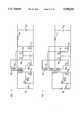
- FIG. 1is a schematic of a clamped forward converter with a drive for a self synchronized synchronous rectifier
- FIG. 2is a graph of waveforms to assist in describing the operation of the converter of FIG. 1;
- FIG. 3 through 14are schematics of other versions of a self synchronized synchronous rectifier, embodying the principles of the invention.
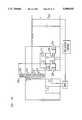
- FIG. 15is a clamped forward converter with an alternate drive for a self-synchronized synchronous rectifier.
- FIG. 16is a generalized circuit diagram embodying the principles introduced in FIG. 15.
- a power convertersuch as shown in FIG. 1, includes a main FET power switch 101 connected to and periodically switched to enable an input DC voltage to be applied to the primary winding 112 of the power transformer 102.
- An auxiliary switch 103 and a capacitor 107 connected in series and placed in shunt connection with the power switch 101operates to clamp the voltage level across the primary and secondary windings during non conducting intervals of the power switch 101. This assures that a voltage exists at the transformer windings over the entire time of non-conduction of the main power switch to assure drive for synchronous rectifier devices connected in the secondary circuit.
- the secondary winding 111is connected to two rectifier switches 105 and 106 which are controllably switched to rectify the periodic waveform supplied to the rectifier by the secondary winding 111.
- a low pass filter including inductor 104acts on the rectified waveform to supply the output voltage V out .
- a regulation control 121senses the output voltage V out , via lead 127, and controls the duty cycle of the main power switch 101 and auxiliary switch 103, via the drive circuit 122.
- the power transformer 102includes a third or auxiliary winding 110 having a winding polarity so that its voltage is utilized to appropriately drive the FET synchronous rectifier switches 105 and 106.
- Drive to the FET synchronous rectifier switches 105 and 106is applied through the drain-source path of the gate drive FET devices 109 and 108 respectively.
- the drive levelis determined by the turn ratio of the auxiliary winding 110 with respect to the primary winding 112, selected to assure that there is sufficient drive for the gates of synchronous rectifier switches 105 and 106 over the entire operating cycle and permitted range of input voltage V in .
- the FET devices 108 and 109limit the voltage applied to the gates of the synchronous rectifier switches 105 and 106 to reduce dissipative losses and to reduce the possibility of voltage overstress of the switches 105 and 106.
- a voltage source V bis used to supply a bias voltage to the FET devices 108 and 109.
- the operation of the convertermay be readily understood through the following description and by reference to the voltage waveforms shown in the FIG. 2.
- the power switch 101is non-conducting and the auxiliary switch 103 is conducting with substantially zero impedance in its main conductive path.
- the voltages ⁇ 111 across winding 111 and ⁇ 110 across winding 110(dotted ends are positive with respect to undotted ends) are determined by the respective turn ratios. Typically more turns are included in winding 110 to boost the synchronous-rectifier drive voltage above that available at winding 111.
- Non-conductance of switch 108clamps the voltage at the gate of switch 106 to a value determined by the difference between the DC bias voltage V b connected to the gate of switch 108 and the threshold voltage of the switch 108.
- the switches 101 and 103change state, after which switch 101 is non-conducting and switch 103 is conducting. For a short period during this interval, the drain-source channel of neither switch 105 or 106 is conducting and the output inductor current is conducted through the body diodes comprising a part of the switch of these devices.
- a negative voltage V in minus V c107is impressed across the primary winding 112 of transformer 102 causing the voltage across the secondary winding 111 and auxiliary winding 110 to reverse.
- switch 108is non-conducting and switch 109 is conducting.
- the negative voltage V 110 across winding 110causes the gate to source capacitance of switch 106 to discharge through the body diode of switch 108.
- the gate to source capacitance of switch 105is charged and the enabled switch 105 and output inductor 104 carry the load current.
- Circuit resonancesare produced by the switching in the circuit due to the interaction between parasitic capacitances and inductances of the circuit. These resonances cause tinging in the drain-to-source voltage waveforms of switches 105 and 106 and as shown by the waveforms of FIG. 2 as they change conductive states. Coupling of these tinging voltages through the parasitic drain-to-gate capacitances of switches 105 and 106 could cause them to inappropriately conduct, however the bias circuit arrangement described herein causes negating voltages to be clamped across the gate to source terminals of switches 105 and 106 when they are normally non-conducting. Hence temporary voltage increases can not inadvertently turn on these devices and cause turn on losses that impair circuit efficiency.
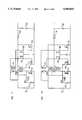
- the circuit of FIG. 3discloses a flyback converter having a drive winding on the power transformer.
- the output filteris connected to a tap in the power secondary winding to achieve both forward and flyback mode operation.
- the drive winding for the synchronous rectifiersis contained in a separate drive transformer rather than the power transformer 102.
- the primary winding of the drive transformer 110, and a series connected capacitor (to block DC current)are connected across the power switch 101.
- This drive circuitis shown in a forward converter in FIG. 5, a flyback converter in FIG. 6, and a converter with a tapped secondary winding in FIG. 7.
- the drive transformer and capacitorare connected instead across a winding of the power transformer 102.
- This drive configurationis shown for the same three basic converters, a forward converter in FIG. 8, a flyback converter in FIG. 9, and a converter with a tapped secondary winding in FIG. 10.
- FIG. 11is a schematic diagram that represents all nine of the aforementioned circuit variations; i.e., all combinations of three circuit topologies and three possible locations of the synchronous-rectifier drive winding.
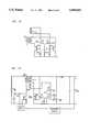
- FIGS. 12 through 14show part of the circuit of FIG. 11, to illustrate some further circuit variations that embody the principles of the invention and can be applied to any of the nine aforementioned circuits.
- the drive circuit in FIG. 12accomplishes the same action as that in FIG. 11, but for a different kind of synchronous rectifier switch.
- This switchis biased conducting when the gate-to-source voltage is zero or positive, and it is biased nonconducting by a negative gate-to-source voltage.
- Diodes 121 and 122which may be intrinsic to synchronous-rectifier switches 105 and 106, limit the positive voltage applied to the gate electrodes of the switches.
- Switches 117 and 118, along with the voltage source V plimit the negative voltage applied to the gate electrodes of 105 and 106. In the embodiment shown in FIG.
- FETs 117 and 118are p-channel enhancement-mode FETs, which turn on when the gate-to-source voltage is less than the negative threshold voltage of the device. These switches also contain intrinsic body diodes that conduct to permit turning on the corresponding synchronous-rectifier switch.
- FIGS. 13 and 14show other variations on the circuit of FIG. 11, with either synchronous-rectifier switch replaced by a diode.
- synchronous-rectifier switch 105 in HG. 11can be replaced by diode 113 in FIG. 13, with capacitor 115 substituted for the gate-to-source capacitance of switch 105.
- synchronous-rectifier switch 106 in FIG. 11can be replaced by diode 114 in FIG. 14, with capacitor 116 substituted for the gate-to-source capacitance of switch 106.
- These circuitsoperate in essentially the same manner as described previously for FIG. 1, except that a diode is conducting during one portion of the switching cycle instead of a synchronous-rectifier switch.
- FIG. 15Another means of boosting the drive voltage for self-driven synchronous rectifiers is illustrated in FIG. 15.
- the voltage available at the secondary power winding 211is sufficient to drive one of the two synchronous-rectifier switches, 206, but not to drive the other, switch 205.
- the solutionis to add drive winding 210 to the main power transformer 202, with one lead connected to the secondary power winding 211 and the other lead connected in series with one or two voltage-limiting switches and the control electrode of synchronous-rectifier switch 205.
- Gate-drive switches 209 and 208are included as in FIG. 1 to limit the positive voltage applied to the gates of the synchronous rectifier switches.
- New gate-drive switch 217 and new bias voltage V pare included to limit the "off" voltage applied to the gate of switch 205 during the time synchronous rectifier switch 206 is conducting.
- gate-drive currentcan flow through the body diode of p-channel FET 217, but during turn-off, gate-drive current flows through the channel of switch 217 until its source voltage (between switches 209 and 217) falls to less than -V p minus the negative threshold voltage of switch 217. This action protects the gate of synchronous-rectifier switch 205 from excessive negative voltage.
- FIG. 16is a generalized diagram of the invention illustrated in FIG. 15, and a circuit suitable for the alternate type of synchronous-rectifier switch introduced in FIG. 12.
- Both portions 211 and 219 of the power secondary windingmay be present, yielding an isolated buck converter with a tapped secondary winding, or the turns of winding 219 may be set to zero, yielding a forward converter as in FIG. 15, or the turns of winding 211 may be set to zero, giving a flyback converter.
- the turns of either drive winding 210 or 218may be set to zero if sufficient drive voltage is present for a particular design and range of operating conditions.
- Either of switches 208 and 216may be eliminated, and either of switches 209 and 217 may be eliminated, as long as the associated gate voltage is not excessive.
- either synchronous-rectifier switch 205 or 206may be replaced by a diode, if desired. Any of these circuit variations embodies the principles of the invention.
Landscapes
- Engineering & Computer Science (AREA)
- Power Engineering (AREA)
- Dc-Dc Converters (AREA)
Abstract
Description
Claims (28)
Priority Applications (2)
| Application Number | Priority Date | Filing Date | Title |
|---|---|---|---|
| US08/452,560US5590032A (en) | 1995-05-25 | 1995-05-25 | Self-synchronized drive circuit for a synchronous rectifier in a clamped-mode power converter |
| US09/244,624USRE37510E1 (en) | 1995-05-25 | 1998-12-17 | Self-synchronized drive circuit for a synchronized rectifier in a clamped-mode power converter |
Applications Claiming Priority (1)
| Application Number | Priority Date | Filing Date | Title |
|---|---|---|---|
| US08/452,560US5590032A (en) | 1995-05-25 | 1995-05-25 | Self-synchronized drive circuit for a synchronous rectifier in a clamped-mode power converter |
Related Child Applications (1)
| Application Number | Title | Priority Date | Filing Date |
|---|---|---|---|
| US09/244,624ReissueUSRE37510E1 (en) | 1995-05-25 | 1998-12-17 | Self-synchronized drive circuit for a synchronized rectifier in a clamped-mode power converter |
Publications (1)
| Publication Number | Publication Date |
|---|---|
| US5590032Atrue US5590032A (en) | 1996-12-31 |
Family
ID=23796960
Family Applications (2)
| Application Number | Title | Priority Date | Filing Date |
|---|---|---|---|
| US08/452,560CeasedUS5590032A (en) | 1995-05-25 | 1995-05-25 | Self-synchronized drive circuit for a synchronous rectifier in a clamped-mode power converter |
| US09/244,624Expired - LifetimeUSRE37510E1 (en) | 1995-05-25 | 1998-12-17 | Self-synchronized drive circuit for a synchronized rectifier in a clamped-mode power converter |
Family Applications After (1)
| Application Number | Title | Priority Date | Filing Date |
|---|---|---|---|
| US09/244,624Expired - LifetimeUSRE37510E1 (en) | 1995-05-25 | 1998-12-17 | Self-synchronized drive circuit for a synchronized rectifier in a clamped-mode power converter |
Country Status (1)
| Country | Link |
|---|---|
| US (2) | US5590032A (en) |
Cited By (64)
| Publication number | Priority date | Publication date | Assignee | Title |
|---|---|---|---|---|
| US5734563A (en)* | 1995-06-01 | 1998-03-31 | Nec Corporation | Synchronous rectification type converter |
| US5774350A (en)* | 1995-04-07 | 1998-06-30 | Sgs-Thomson Microelectronics S.A. | Integrated low dissipation power controller |
| US5870299A (en)* | 1997-05-28 | 1999-02-09 | Lucent Technologies Inc. | Method and apparatus for damping ringing in self-driven synchronous rectifiers |
| US5978238A (en)* | 1998-04-02 | 1999-11-02 | Lucent Technologies Inc. | Active clamp for buck-based converter and method of operation thereof |
| US6002597A (en)* | 1999-02-08 | 1999-12-14 | Lucent Technologies Inc. | Synchronous rectifier having dynamically adjustable current rating and method of operation thereof |
| US6005773A (en)* | 1996-12-23 | 1999-12-21 | Lucent Technologies Inc. | Board-mountable power supply module |
| US6011703A (en)* | 1997-07-30 | 2000-01-04 | Lucent Technologies Inc. | Self-synchronized gate drive for power converter employing self-driven synchronous rectifier and method of operation thereof |
| US6021059A (en)* | 1998-12-31 | 2000-02-01 | Honeywell Inc. | Integrated synchronous rectifier for power supplies |
| US6038148A (en)* | 1998-12-11 | 2000-03-14 | Ericsson, Inc. | Self-driven synchronous rectification scheme |
| JP3022535B1 (en) | 1998-12-16 | 2000-03-21 | 日本電気株式会社 | Synchronous rectification circuit |
| US6058026A (en)* | 1999-07-26 | 2000-05-02 | Lucent Technologies, Inc. | Multiple output converter having a single transformer winding and independent output regulation |
| US6061255A (en)* | 1999-06-04 | 2000-05-09 | Astec International Limited | Drive circuit for synchronous rectifiers in isolated forward converter |
| US6061260A (en)* | 1998-08-19 | 2000-05-09 | Lucent Technology Inc. | Board mounted power supply having an auxiliary output |
| US6069799A (en)* | 1997-05-14 | 2000-05-30 | Lucent Technologies Inc. | Self-synchronized drive circuit for a synchronous rectifier in a clamped-mode power converter |
| US6091616A (en)* | 1998-10-21 | 2000-07-18 | Lucent Technologies Inc. | Drive compensation circuit for synchronous rectifier and method of operating the same |
| US6104623A (en)* | 1999-10-21 | 2000-08-15 | Lucent Technologies, Inc. | Multiple output converter having secondary regulator using self-driven synchronous rectifiers |
| US6128206A (en)* | 1999-03-12 | 2000-10-03 | Ericsson, Inc. | Clamping circuit and method for synchronous rectification |
| EP1037221A3 (en)* | 1999-03-11 | 2000-10-04 | Murata Manufacturing Co., Ltd. | Coil device and switching power supply apparatus using the same |
| US6130828A (en)* | 1999-08-26 | 2000-10-10 | Lucent Technologies, Inc. | Multiple output converter having self-synchronized pulse width modulation regulation |
| US6181588B1 (en) | 1998-09-25 | 2001-01-30 | Dell Usa, L.P. | Constant polarity input device including synchronous bridge rectifier |
| US6181578B1 (en)* | 2000-04-06 | 2001-01-30 | Astec International Limited | Synchronous rectifier drive mechanism for resonant reset forward converters |
| US6181577B1 (en) | 1999-07-26 | 2001-01-30 | Lucent Technologies Inc. | Auxiliary bias circuit for a power supply and a method of operation thereof |
| US6215271B1 (en) | 1999-05-11 | 2001-04-10 | Satcon Technology Corporation | Charging system having a controlled rectifier bridge and a single voltage sensor |
| US6218891B1 (en) | 2000-07-28 | 2001-04-17 | Lucent Technologies Inc. | Integrated circuit including a driver for a metal-semiconductor field-effect transistor |
| US6219264B1 (en)* | 1999-07-29 | 2001-04-17 | Intel Corporation | Method and apparatus to reduce rectifier loss |
| US6239582B1 (en) | 1999-11-04 | 2001-05-29 | Satcon Technology Corporation | Motor vehicle alternator having a single voltage sensor and a half-wave controlled rectifier bridge for increasing output |
| US6243278B1 (en) | 2000-04-04 | 2001-06-05 | Tyco Electronics Logistics A.G. | Drive circuit for synchronous rectifier and method of operating the same |
| US6256214B1 (en) | 1999-03-11 | 2001-07-03 | Ericsson Inc. | General self-driven synchronous rectification scheme for synchronous rectifiers having a floating gate |
| US6275401B1 (en) | 2000-01-10 | 2001-08-14 | Power-One, Inc. | Self-driven synchronous rectification circuit for low output voltage DC-DC converters |
| US6301139B1 (en) | 2000-04-06 | 2001-10-09 | Power-One, Inc. | Self-driven synchronous rectifier circuit for non-optimal reset secondary voltage |
| US6396725B1 (en) | 2000-07-31 | 2002-05-28 | Mark E. Jacobs | System and method for improving control loop response of a power supply |
| US6400580B1 (en) | 2000-10-10 | 2002-06-04 | Wayne C. Bowman | System and method for reducing a DC magnetic flux bias in a transformer and power converter employing the same |
| US6421262B1 (en)* | 2000-02-08 | 2002-07-16 | Vlt Corporation | Active rectifier |
| US6459600B2 (en) | 2000-01-28 | 2002-10-01 | Ericsson, Inc. | Method of connecting synchronous rectifier modules in parallel without output voltage faults |
| FR2826523A1 (en)* | 2001-06-25 | 2002-12-27 | Cit Alcatel | SELF-CONTROLLED SYNCHRONOUS RECTIFIER |
| EP1229635A3 (en)* | 2001-01-25 | 2003-02-05 | Texas Instruments Incorporated | Active gate clamp circuit for self driven synchronous rectifiers |
| EP1104084A3 (en)* | 1999-11-25 | 2003-05-21 | Drenkrum Limited | Efficient parallel connection of improved power-supplies |
| US6628532B1 (en) | 2000-08-08 | 2003-09-30 | Artesyn Technologies, Inc | Drive circuit for a voltage-controlled switch |
| US20030198064A1 (en)* | 2002-01-16 | 2003-10-23 | Ballard Power Systems Corporation | Device and method of commutation control for an isolated boost converter |
| WO2004001937A1 (en)* | 2002-06-19 | 2003-12-31 | Sanken Electric Co., Ltd. | Sc-dc converter |
| US6674658B2 (en) | 2001-02-09 | 2004-01-06 | Netpower Technologies, Inc. | Power converter including circuits for improved operational control of synchronous rectifiers therein |
| US20040047164A1 (en)* | 2001-02-01 | 2004-03-11 | Brkovic Milivoje S. | Isolated drive circuitry used in switch-mode power converters |
| US6728118B1 (en)* | 2002-11-13 | 2004-04-27 | Innoveta Technologies, Inc. | Highly efficient, tightly regulated DC-to-DC converter |
| US20040145920A1 (en)* | 2003-01-24 | 2004-07-29 | Ming Xu | Self-driven circuit for synchronous rectifier DC/DC converter |
| US20040184289A1 (en)* | 2002-01-31 | 2004-09-23 | Vlt Corporation, A Texas Corporation | Output resistance modulation in power converters |
| EP1333566A3 (en)* | 2002-01-31 | 2004-11-10 | Vlt Corporation | Driving a control unit of one or more switching devices |
| US20060139967A1 (en)* | 2004-12-29 | 2006-06-29 | Quitayen Astros M | Synchronous rectifier drive circuit for low output voltage active clamp forward converter |
| US7102898B2 (en)* | 2001-02-01 | 2006-09-05 | Di/Dt, Inc. | Isolated drive circuitry used in switch-mode power converters |
| US20060203522A1 (en)* | 2005-03-08 | 2006-09-14 | John Hensel | Self-synchronized high voltage synchronous rectifier and drive |
| US7558083B2 (en) | 1997-01-24 | 2009-07-07 | Synqor, Inc. | High efficiency power converter |
| US7564702B2 (en) | 1997-01-24 | 2009-07-21 | Synqor, Inc. | High efficiency power converter |
| US20090290391A1 (en)* | 2008-05-20 | 2009-11-26 | Harris Corporation | Self-driven synchronous rectifier |
| EP1236265B1 (en)* | 1999-11-05 | 2012-01-18 | Ericsson, Inc. | Externally-driven scheme for synchronous rectification |
| WO2012104062A1 (en)* | 2011-01-31 | 2012-08-09 | Tridonic Uk Ltd. | Driver circuit for organic led |
| US20130121039A1 (en)* | 2011-11-15 | 2013-05-16 | Wen-Hsiung Hsieh | Switching amplifier with pulsed current supply |
| CN103368425A (en)* | 2013-08-05 | 2013-10-23 | 北京新雷能科技股份有限公司 | Synchronous rectification driving circuit |
| CN104079190A (en)* | 2014-05-21 | 2014-10-01 | 杰华特微电子(杭州)有限公司 | Synchronous rectification control method |
| US8934267B2 (en) | 2010-11-09 | 2015-01-13 | Tdk-Lambda Corporation | Loosely regulated feedback control for high efficiency isolated DC-DC converters |
| CN105099232A (en)* | 2014-05-07 | 2015-11-25 | 武汉永力睿源科技有限公司 | Synchronous rectification drive circuit for active clamping forward converter |
| US9520772B2 (en) | 2010-11-09 | 2016-12-13 | Tdk-Lambda Corporation | Multi-level voltage regulator system |
| US9564818B2 (en) | 2013-08-26 | 2017-02-07 | Rohm Co., Ltd | DC/DC converter capable of preventing overvoltage and overcurrent, operation method thereof and electronic apparatus |
| US10199950B1 (en) | 2013-07-02 | 2019-02-05 | Vlt, Inc. | Power distribution architecture with series-connected bus converter |
| US20190089263A1 (en)* | 2017-09-19 | 2019-03-21 | Texas Instruments Incorporated | Isolated dc-dc converter |
| US20190097544A1 (en) | 2017-09-22 | 2019-03-28 | Texas Instruments Incorporated | Isolated phase shifted dc to dc converter with secondary side regulation and sense coil to reconstruct primary phase |
Families Citing this family (8)
| Publication number | Priority date | Publication date | Assignee | Title |
|---|---|---|---|---|
| US7272021B2 (en)* | 1997-01-24 | 2007-09-18 | Synqor, Inc. | Power converter with isolated and regulated stages |
| US6535400B2 (en)* | 2001-03-30 | 2003-03-18 | Texas Instruments Incorporated | Control circuit for synchronous rectifiers in DC/DC converters to reduce body diode conduction losses |
| TW588497B (en)* | 2002-07-30 | 2004-05-21 | Delta Electronics Inc | Synchronous rectifier of intermittent control and its control method |
| JP4669341B2 (en)* | 2005-07-29 | 2011-04-13 | パイオニア株式会社 | Charge pump circuit for switching power supply |
| CN100525044C (en)* | 2005-11-28 | 2009-08-05 | 伊博电源(杭州)有限公司 | Self driving circuit for three winding reverse exciting converter synchronous rectifier |
| TWM333007U (en)* | 2007-11-23 | 2008-05-21 | Power Mate Technology Co Ltd | Synchronized-rectification driving circuit |
| CN103580484B (en)* | 2012-07-30 | 2015-10-21 | 台达电子工业股份有限公司 | Synchronous rectification device and its control method |
| TWI692189B (en) | 2019-01-31 | 2020-04-21 | 宏碁股份有限公司 | Power conversion device |
Citations (5)
| Publication number | Priority date | Publication date | Assignee | Title |
|---|---|---|---|---|
| US5066900A (en)* | 1989-11-14 | 1991-11-19 | Computer Products, Inc. | Dc/dc converter switching at zero voltage |
| US5303138A (en)* | 1993-04-29 | 1994-04-12 | At&T Bell Laboratories | Low loss synchronous rectifier for application to clamped-mode power converters |
| US5353212A (en)* | 1992-04-20 | 1994-10-04 | At&T Bell Laboratories | Zero-voltage switching power converter with ripple current cancellation |
| US5528480A (en)* | 1994-04-28 | 1996-06-18 | Elonex Technologies, Inc. | Highly efficient rectifying and converting circuit for computer power supplies |
| US5535112A (en)* | 1993-03-31 | 1996-07-09 | Alcatel N.V. | DC/DC conversion circuit |
Family Cites Families (29)
| Publication number | Priority date | Publication date | Assignee | Title |
|---|---|---|---|---|
| US3989995A (en) | 1975-05-05 | 1976-11-02 | Bell Telephone Laboratories, Incorporated | Frequency stabilized single-ended regulated converter circuit |
| SU892614A1 (en) | 1980-04-11 | 1981-12-23 | Московский Ордена Ленина Энергетический Институт | One-cycle dc voltage regulator |
| JPS57138867A (en) | 1981-02-17 | 1982-08-27 | Toshiba Corp | Voltage resonance type high frequency switching circuit |
| US4441146A (en) | 1982-02-04 | 1984-04-03 | Vicor Corporation | Optimal resetting of the transformer's core in single ended forward converters |
| US4618919A (en) | 1984-10-04 | 1986-10-21 | Sperry Corporation | Topology for miniature power supply with low voltage and low ripple requirements |
| US4716514A (en)* | 1984-12-13 | 1987-12-29 | Unitrode Corporation | Synchronous power rectifier |
| EP0289186A3 (en) | 1987-04-23 | 1990-04-04 | International Minerals And Chemical Corporation | Process for increasing the growth rate and enhancing the feed efficiency of meat producing livestock |
| US4788634A (en) | 1987-06-22 | 1988-11-29 | Massachusetts Institute Of Technology | Resonant forward converter |
| DK382687A (en) | 1987-07-22 | 1989-04-14 | Scanpower | POWER SUPPLY CIRCUIT |
| US4857822A (en)* | 1987-09-23 | 1989-08-15 | Virginia Tech Intellectual Properties, Inc. | Zero-voltage-switched multi-resonant converters including the buck and forward type |
| US4809148A (en) | 1987-10-21 | 1989-02-28 | British Columbia Telephone Company | Full-fluxed, single-ended DC converter |
| US4945467A (en) | 1988-02-26 | 1990-07-31 | Black & Decker Inc. | Multiple-mode voltage converter |
| US4903189A (en) | 1988-04-27 | 1990-02-20 | General Electric Company | Low noise, high frequency synchronous rectifier |
| US4870555A (en) | 1988-10-14 | 1989-09-26 | Compaq Computer Corporation | High-efficiency DC-to-DC power supply with synchronous rectification |
| US4931716A (en) | 1989-05-05 | 1990-06-05 | Milan Jovanovic | Constant frequency zero-voltage-switching multi-resonant converter |
| JPH0734653B2 (en) | 1989-09-05 | 1995-04-12 | 九州大学長 | Power supply |
| US4975821A (en) | 1989-10-10 | 1990-12-04 | Lethellier Patrice R | High frequency switched mode resonant commutation power supply |
| US4959764A (en) | 1989-11-14 | 1990-09-25 | Computer Products, Inc. | DC/DC converter switching at zero voltage |
| US5231563A (en) | 1990-09-07 | 1993-07-27 | Itt Corporation | Square wave converter having an improved zero voltage switching operation |
| US5126931A (en) | 1990-09-07 | 1992-06-30 | Itt Corporation | Fixed frequency single ended forward converter switching at zero voltage |
| US5291382A (en) | 1991-04-10 | 1994-03-01 | Lambda Electronics Inc. | Pulse width modulated DC/DC converter with reduced ripple current coponent stress and zero voltage switching capability |
| US5126651A (en) | 1991-07-26 | 1992-06-30 | Motorola, Inc. | Gate drive circuit for a synchronous rectifier |
| US5179512A (en) | 1991-09-18 | 1993-01-12 | General Electric Company | Gate drive for synchronous rectifiers in resonant converters |
| US5268830A (en)* | 1992-04-20 | 1993-12-07 | At&T Bell Laboratories | Drive circuit for power switches of a zero-voltage switching power converter |
| US5274543A (en)* | 1992-04-20 | 1993-12-28 | At&T Bell Laboratories | Zero-voltage switching power converter with lossless synchronous rectifier gate drive |
| EP0602835B1 (en) | 1992-12-15 | 1996-05-01 | AT&T Corp. | Voltage control circuits |
| US5282123A (en) | 1992-12-16 | 1994-01-25 | At&T Bell Laboratories | Clamped mode DC-DC converter |
| US5434768A (en) | 1993-02-12 | 1995-07-18 | Rompower | Fixed frequency converter switching at zero voltage |
| EP0660977B1 (en) | 1993-07-14 | 1998-05-13 | Melcher Ag | Synchronous rectifier resistant to feedback |
- 1995
- 1995-05-25USUS08/452,560patent/US5590032A/ennot_activeCeased
- 1998
- 1998-12-17USUS09/244,624patent/USRE37510E1/ennot_activeExpired - Lifetime
Patent Citations (5)
| Publication number | Priority date | Publication date | Assignee | Title |
|---|---|---|---|---|
| US5066900A (en)* | 1989-11-14 | 1991-11-19 | Computer Products, Inc. | Dc/dc converter switching at zero voltage |
| US5353212A (en)* | 1992-04-20 | 1994-10-04 | At&T Bell Laboratories | Zero-voltage switching power converter with ripple current cancellation |
| US5535112A (en)* | 1993-03-31 | 1996-07-09 | Alcatel N.V. | DC/DC conversion circuit |
| US5303138A (en)* | 1993-04-29 | 1994-04-12 | At&T Bell Laboratories | Low loss synchronous rectifier for application to clamped-mode power converters |
| US5528480A (en)* | 1994-04-28 | 1996-06-18 | Elonex Technologies, Inc. | Highly efficient rectifying and converting circuit for computer power supplies |
Non-Patent Citations (24)
| Title |
|---|
| Alexander, M., Blanchard, R., Severns, R., "MOSFETs Move in on Low Voltage Rectification", Mospower Applications Handbook, Siliconix Technical Article, 1982, Siliconix, Inc. |
| Alexander, M., Blanchard, R., Severns, R., MOSFETs Move in on Low Voltage Rectification , Mospower Applications Handbook, Siliconix Technical Article, 1982, Siliconix, Inc.* |
| Blanc, J., "Practical Application of MOSFET Synchronous Rectifiers", Intelec 1991 Proceedings, pp. 495-501. |
| Blanc, J., Practical Application of MOSFET Synchronous Rectifiers , Intelec 1991 Proceedings, pp. 495 501.* |
| Carsten, B., "High Power SMPS Require Intrinsic Reliability", PCI Proceedings, Mar. 29, 1982, p. 456 ff. |
| Carsten, B., "High-Power SMPS Require Intrinsic Reliabillity", PCI Proceedings, Sep. 14, 1981, pp. 118-133. |
| Carsten, B., High Power SMPS Require Intrinsic Reliability , PCI Proceedings, Mar. 29, 1982, p. 456 ff.* |
| Carsten, B., High Power SMPS Require Intrinsic Reliabillity , PCI Proceedings, Sep. 14, 1981, pp. 118 133.* |
| Cobos, J. A., Uceds, J., et al, "Resonant Reset Forward Topoligies for Low Output Voltage On-Board Converters", Conference Proceeding of the 9th Annual Applied Power Electronics Conference and Expositio, p. 703, vol. 2. |
| Cobos, J. A., Uceds, J., et al, Resonant Reset Forward Topoligies for Low Output Voltage On Board Converters , Conference Proceeding of the 9th Annual Applied Power Electronics Conference and Expositio, p. 703, vol. 2.* |
| Huber, L., and Lee, F. C., et al, "Design of a High-Efficiency Power Converter for a Satellite Solid-State Power Amplifier", Conference Proceedings of the 9th Annual Applied Power Electronics Conference and Exposition, p. 645, vol. 2. |
| Huber, L., and Lee, F. C., et al, Design of a High Efficiency Power Converter for a Satellite Solid State Power Amplifier , Conference Proceedings of the 9th Annual Applied Power Electronics Conference and Exposition, p. 645, vol. 2.* |
| Jitaru, I. D., "Constant Frequency, Forward Converter With Resonant Transitions," HFPC '91 Proceedings, pp. 282-292. |
| Jitaru, I. D., Constant Frequency, Forward Converter With Resonant Transitions, HFPC 91 Proceedings, pp. 282 292.* |
| Jitaru, I., Dan and Cocian, George, "High Efficiency DC-DC Converter", Conference Proceeding of the 9th Annual Applied Power Electronics Converence and Exposition, p. 639, vol. 2. |
| Jitaru, I., Dan and Cocian, George, High Efficiency DC DC Converter , Conference Proceeding of the 9th Annual Applied Power Electronics Converence and Exposition, p. 639, vol. 2.* |
| Kagan, R., Chi, M., "Improving Power Supply Efficiency with MOSFET Synchronous Rectifiers", Proceedings of PowerCon9, 1982. |
| Kagan, R., Chi, M., Improving Power Supply Efficiency with MOSFET Synchronous Rectifiers , Proceedings of PowerCon9, 1982.* |
| Murakami, N., et al, "A Highly Efficient, Low-Profile 300W Power Pack for Telecommunications Systems", Conference Proceedings of the 9th Annual Applied Power Electronics Conference and Exposition, p. 786, vol. 2. |
| Murakami, N., et al, A Highly Efficient, Low Profile 300W Power Pack for Telecommunications Systems , Conference Proceedings of the 9th Annual Applied Power Electronics Conference and Exposition, p. 786, vol. 2.* |
| Murakami, N., Namiki, H., Sakakibara, K., Yachi, T., "A Simple and Efficient Synchronous Rectifier for Forward DC-DC Converters", APEC 1993 Proceedings, pp. 463-468. |
| Murakami, N., Namiki, H., Sakakibara, K., Yachi, T., A Simple and Efficient Synchronous Rectifier for Forward DC DC Converters , APEC 1993 Proceedings, pp. 463 468.* |
| Tabisz, W., Lee, F. C. Chen, D., "A MOSFET Resonant Synchronous Rectifier for High Frequency DC/DC Converters", PESC 1990 Proceedings, pp. 769-779. |
| Tabisz, W., Lee, F. C. Chen, D., A MOSFET Resonant Synchronous Rectifier for High Frequency DC/DC Converters , PESC 1990 Proceedings, pp. 769 779.* |
Cited By (103)
| Publication number | Priority date | Publication date | Assignee | Title |
|---|---|---|---|---|
| US5774350A (en)* | 1995-04-07 | 1998-06-30 | Sgs-Thomson Microelectronics S.A. | Integrated low dissipation power controller |
| US5734563A (en)* | 1995-06-01 | 1998-03-31 | Nec Corporation | Synchronous rectification type converter |
| US6005773A (en)* | 1996-12-23 | 1999-12-21 | Lucent Technologies Inc. | Board-mountable power supply module |
| US7558083B2 (en) | 1997-01-24 | 2009-07-07 | Synqor, Inc. | High efficiency power converter |
| US9143042B2 (en) | 1997-01-24 | 2015-09-22 | Synqor, Inc. | High efficiency power converter |
| US8493751B2 (en) | 1997-01-24 | 2013-07-23 | Synqor, Inc. | High efficiency power converter |
| US8023290B2 (en) | 1997-01-24 | 2011-09-20 | Synqor, Inc. | High efficiency power converter |
| US7564702B2 (en) | 1997-01-24 | 2009-07-21 | Synqor, Inc. | High efficiency power converter |
| US6069799A (en)* | 1997-05-14 | 2000-05-30 | Lucent Technologies Inc. | Self-synchronized drive circuit for a synchronous rectifier in a clamped-mode power converter |
| US5870299A (en)* | 1997-05-28 | 1999-02-09 | Lucent Technologies Inc. | Method and apparatus for damping ringing in self-driven synchronous rectifiers |
| US6011703A (en)* | 1997-07-30 | 2000-01-04 | Lucent Technologies Inc. | Self-synchronized gate drive for power converter employing self-driven synchronous rectifier and method of operation thereof |
| US5978238A (en)* | 1998-04-02 | 1999-11-02 | Lucent Technologies Inc. | Active clamp for buck-based converter and method of operation thereof |
| US6061260A (en)* | 1998-08-19 | 2000-05-09 | Lucent Technology Inc. | Board mounted power supply having an auxiliary output |
| US6181588B1 (en) | 1998-09-25 | 2001-01-30 | Dell Usa, L.P. | Constant polarity input device including synchronous bridge rectifier |
| US6288920B1 (en)* | 1998-10-21 | 2001-09-11 | Mark E. Jacobs | Drive compensation circuit for synchronous rectifier and method of operating the same |
| US6091616A (en)* | 1998-10-21 | 2000-07-18 | Lucent Technologies Inc. | Drive compensation circuit for synchronous rectifier and method of operating the same |
| EP0996219A3 (en)* | 1998-10-21 | 2000-07-19 | Lucent Technologies Inc. | Drive compensation circuit for synchronous rectifier and method of operating the same |
| WO2000035071A1 (en)* | 1998-12-11 | 2000-06-15 | Ericsson, Inc. | Self-drive synchronous rectification scheme |
| KR100852550B1 (en)* | 1998-12-11 | 2008-08-18 | 에릭슨 인크. | A method and circuit for self-driven synchronous rectification |
| JP2002533045A (en)* | 1998-12-11 | 2002-10-02 | エリクソン, インコーポレイテッド | Self-driven synchronous rectification |
| US6038148A (en)* | 1998-12-11 | 2000-03-14 | Ericsson, Inc. | Self-driven synchronous rectification scheme |
| JP3022535B1 (en) | 1998-12-16 | 2000-03-21 | 日本電気株式会社 | Synchronous rectification circuit |
| US6021059A (en)* | 1998-12-31 | 2000-02-01 | Honeywell Inc. | Integrated synchronous rectifier for power supplies |
| US6002597A (en)* | 1999-02-08 | 1999-12-14 | Lucent Technologies Inc. | Synchronous rectifier having dynamically adjustable current rating and method of operation thereof |
| US6281779B1 (en) | 1999-03-11 | 2001-08-28 | Murata Manufacturing Co., Ltd. | Coil device and switching power supply apparatus using the same |
| EP1037221A3 (en)* | 1999-03-11 | 2000-10-04 | Murata Manufacturing Co., Ltd. | Coil device and switching power supply apparatus using the same |
| US6256214B1 (en) | 1999-03-11 | 2001-07-03 | Ericsson Inc. | General self-driven synchronous rectification scheme for synchronous rectifiers having a floating gate |
| US6128206A (en)* | 1999-03-12 | 2000-10-03 | Ericsson, Inc. | Clamping circuit and method for synchronous rectification |
| US6215271B1 (en) | 1999-05-11 | 2001-04-10 | Satcon Technology Corporation | Charging system having a controlled rectifier bridge and a single voltage sensor |
| US6061255A (en)* | 1999-06-04 | 2000-05-09 | Astec International Limited | Drive circuit for synchronous rectifiers in isolated forward converter |
| US6058026A (en)* | 1999-07-26 | 2000-05-02 | Lucent Technologies, Inc. | Multiple output converter having a single transformer winding and independent output regulation |
| US6181577B1 (en) | 1999-07-26 | 2001-01-30 | Lucent Technologies Inc. | Auxiliary bias circuit for a power supply and a method of operation thereof |
| US6219264B1 (en)* | 1999-07-29 | 2001-04-17 | Intel Corporation | Method and apparatus to reduce rectifier loss |
| US6130828A (en)* | 1999-08-26 | 2000-10-10 | Lucent Technologies, Inc. | Multiple output converter having self-synchronized pulse width modulation regulation |
| US6104623A (en)* | 1999-10-21 | 2000-08-15 | Lucent Technologies, Inc. | Multiple output converter having secondary regulator using self-driven synchronous rectifiers |
| US6239582B1 (en) | 1999-11-04 | 2001-05-29 | Satcon Technology Corporation | Motor vehicle alternator having a single voltage sensor and a half-wave controlled rectifier bridge for increasing output |
| EP1236265B1 (en)* | 1999-11-05 | 2012-01-18 | Ericsson, Inc. | Externally-driven scheme for synchronous rectification |
| EP1104084A3 (en)* | 1999-11-25 | 2003-05-21 | Drenkrum Limited | Efficient parallel connection of improved power-supplies |
| US6275401B1 (en) | 2000-01-10 | 2001-08-14 | Power-One, Inc. | Self-driven synchronous rectification circuit for low output voltage DC-DC converters |
| US6459600B2 (en) | 2000-01-28 | 2002-10-01 | Ericsson, Inc. | Method of connecting synchronous rectifier modules in parallel without output voltage faults |
| US20020163322A1 (en)* | 2000-02-08 | 2002-11-07 | Vlt Corporation, A Texas Corporation | Active rectifier |
| US6421262B1 (en)* | 2000-02-08 | 2002-07-16 | Vlt Corporation | Active rectifier |
| US7015561B2 (en) | 2000-02-08 | 2006-03-21 | Vlt, Inc. | Active rectifier |
| US6243278B1 (en) | 2000-04-04 | 2001-06-05 | Tyco Electronics Logistics A.G. | Drive circuit for synchronous rectifier and method of operating the same |
| US6181578B1 (en)* | 2000-04-06 | 2001-01-30 | Astec International Limited | Synchronous rectifier drive mechanism for resonant reset forward converters |
| US6301139B1 (en) | 2000-04-06 | 2001-10-09 | Power-One, Inc. | Self-driven synchronous rectifier circuit for non-optimal reset secondary voltage |
| US6218891B1 (en) | 2000-07-28 | 2001-04-17 | Lucent Technologies Inc. | Integrated circuit including a driver for a metal-semiconductor field-effect transistor |
| US6396725B1 (en) | 2000-07-31 | 2002-05-28 | Mark E. Jacobs | System and method for improving control loop response of a power supply |
| US6628532B1 (en) | 2000-08-08 | 2003-09-30 | Artesyn Technologies, Inc | Drive circuit for a voltage-controlled switch |
| US6400580B1 (en) | 2000-10-10 | 2002-06-04 | Wayne C. Bowman | System and method for reducing a DC magnetic flux bias in a transformer and power converter employing the same |
| EP1229635A3 (en)* | 2001-01-25 | 2003-02-05 | Texas Instruments Incorporated | Active gate clamp circuit for self driven synchronous rectifiers |
| US7088602B2 (en)* | 2001-01-25 | 2006-08-08 | Texas Instruments Incorporated | Active gate clamp circuit for self driven synchronous rectifiers |
| US6804125B2 (en) | 2001-02-01 | 2004-10-12 | Di/Dt Inc. | Isolated drive circuitry used in switch-mode power converters |
| US20040047164A1 (en)* | 2001-02-01 | 2004-03-11 | Brkovic Milivoje S. | Isolated drive circuitry used in switch-mode power converters |
| US6791851B2 (en) | 2001-02-01 | 2004-09-14 | Di/Dt, Inc. | Isolated drive circuitry used in switch-mode power converters |
| US7102898B2 (en)* | 2001-02-01 | 2006-09-05 | Di/Dt, Inc. | Isolated drive circuitry used in switch-mode power converters |
| US6674658B2 (en) | 2001-02-09 | 2004-01-06 | Netpower Technologies, Inc. | Power converter including circuits for improved operational control of synchronous rectifiers therein |
| FR2826523A1 (en)* | 2001-06-25 | 2002-12-27 | Cit Alcatel | SELF-CONTROLLED SYNCHRONOUS RECTIFIER |
| US6707650B2 (en) | 2001-06-25 | 2004-03-16 | Alcatel | Self-synchronized synchronous rectifier |
| US20030198064A1 (en)* | 2002-01-16 | 2003-10-23 | Ballard Power Systems Corporation | Device and method of commutation control for an isolated boost converter |
| US6937483B2 (en) | 2002-01-16 | 2005-08-30 | Ballard Power Systems Corporation | Device and method of commutation control for an isolated boost converter |
| EP1333566A3 (en)* | 2002-01-31 | 2004-11-10 | Vlt Corporation | Driving a control unit of one or more switching devices |
| US6934166B2 (en) | 2002-01-31 | 2005-08-23 | Vlt, Inc. | Output resistance modulation in power converters |
| US6911848B2 (en) | 2002-01-31 | 2005-06-28 | Vlt, Inc. | Low-loss transformer-coupled gate driver |
| US20040184289A1 (en)* | 2002-01-31 | 2004-09-23 | Vlt Corporation, A Texas Corporation | Output resistance modulation in power converters |
| US20040183513A1 (en)* | 2002-01-31 | 2004-09-23 | Vlt Corporation, A Texas Corporation | Low-loss transformer-coupled gate driver |
| WO2004001937A1 (en)* | 2002-06-19 | 2003-12-31 | Sanken Electric Co., Ltd. | Sc-dc converter |
| US20040090801A1 (en)* | 2002-11-13 | 2004-05-13 | Qing Chen | Highly efficient, tightly regulated dc-to-dc converter |
| US6728118B1 (en)* | 2002-11-13 | 2004-04-27 | Innoveta Technologies, Inc. | Highly efficient, tightly regulated DC-to-DC converter |
| US20040145920A1 (en)* | 2003-01-24 | 2004-07-29 | Ming Xu | Self-driven circuit for synchronous rectifier DC/DC converter |
| US6819574B2 (en)* | 2003-01-24 | 2004-11-16 | Virginia Tech Intellectual Properties, Inc. | Self-driven circuit for synchronous rectifier DC/DC converter |
| US7196920B2 (en)* | 2004-12-29 | 2007-03-27 | Astec International Limited | Synchronous rectifier drive circuit for low output voltage active clamp forward converter |
| US20060139967A1 (en)* | 2004-12-29 | 2006-06-29 | Quitayen Astros M | Synchronous rectifier drive circuit for low output voltage active clamp forward converter |
| US7375988B2 (en) | 2005-03-08 | 2008-05-20 | Wall Industries, Inc. | Self-synchronized high voltage synchronous rectifier and drive |
| US20060203522A1 (en)* | 2005-03-08 | 2006-09-14 | John Hensel | Self-synchronized high voltage synchronous rectifier and drive |
| US20090290391A1 (en)* | 2008-05-20 | 2009-11-26 | Harris Corporation | Self-driven synchronous rectifier |
| US7751213B2 (en)* | 2008-05-20 | 2010-07-06 | Harris Corporation | Self-driven synchronous rectifier |
| US9520772B2 (en) | 2010-11-09 | 2016-12-13 | Tdk-Lambda Corporation | Multi-level voltage regulator system |
| US10218265B2 (en) | 2010-11-09 | 2019-02-26 | Tdk-Lambda Corporation | State space-based multi-level voltage regulator system |
| US8934267B2 (en) | 2010-11-09 | 2015-01-13 | Tdk-Lambda Corporation | Loosely regulated feedback control for high efficiency isolated DC-DC converters |
| US9143047B2 (en) | 2010-11-09 | 2015-09-22 | Tdk-Lambda Corporation | Loosely regulated feedback control for high efficiency isolated DC-DC converters |
| GB2504220A (en)* | 2011-01-31 | 2014-01-22 | Tridonic Uk Ltd | Driver circuit for organic LED |
| WO2012104062A1 (en)* | 2011-01-31 | 2012-08-09 | Tridonic Uk Ltd. | Driver circuit for organic led |
| US20130121039A1 (en)* | 2011-11-15 | 2013-05-16 | Wen-Hsiung Hsieh | Switching amplifier with pulsed current supply |
| US9602067B2 (en)* | 2011-11-15 | 2017-03-21 | Wen-Hsiung Hsieh | Switching amplifier with pulsed current supply |
| US12395087B1 (en) | 2013-07-02 | 2025-08-19 | Vicor Corporation | Power distribution architecture with series-connected bus converter |
| US11705820B2 (en) | 2013-07-02 | 2023-07-18 | Vicor Corporation | Power distribution architecture with series-connected bus converter |
| US10594223B1 (en) | 2013-07-02 | 2020-03-17 | Vlt, Inc. | Power distribution architecture with series-connected bus converter |
| US10199950B1 (en) | 2013-07-02 | 2019-02-05 | Vlt, Inc. | Power distribution architecture with series-connected bus converter |
| US11075583B1 (en) | 2013-07-02 | 2021-07-27 | Vicor Corporation | Power distribution architecture with series-connected bus converter |
| CN103368425B (en)* | 2013-08-05 | 2016-01-20 | 北京新雷能科技股份有限公司 | A kind of synchronous rectification driving circuit |
| CN103368425A (en)* | 2013-08-05 | 2013-10-23 | 北京新雷能科技股份有限公司 | Synchronous rectification driving circuit |
| US9564818B2 (en) | 2013-08-26 | 2017-02-07 | Rohm Co., Ltd | DC/DC converter capable of preventing overvoltage and overcurrent, operation method thereof and electronic apparatus |
| CN105099232A (en)* | 2014-05-07 | 2015-11-25 | 武汉永力睿源科技有限公司 | Synchronous rectification drive circuit for active clamping forward converter |
| CN104079190B (en)* | 2014-05-21 | 2016-10-26 | 杰华特微电子(杭州)有限公司 | A kind of synchronous rectification control method |
| CN104079190A (en)* | 2014-05-21 | 2014-10-01 | 杰华特微电子(杭州)有限公司 | Synchronous rectification control method |
| US10601332B2 (en) | 2017-09-19 | 2020-03-24 | Texas Instruments Incorporated | Isolated DC-DC converter |
| US10622908B2 (en)* | 2017-09-19 | 2020-04-14 | Texas Instruments Incorporated | Isolated DC-DC converter |
| US20190089263A1 (en)* | 2017-09-19 | 2019-03-21 | Texas Instruments Incorporated | Isolated dc-dc converter |
| US11336193B2 (en) | 2017-09-19 | 2022-05-17 | Texas Instmments Incorporated | Isolated DC-DC converter |
| US10432102B2 (en) | 2017-09-22 | 2019-10-01 | Texas Instruments Incorporated | Isolated phase shifted DC to DC converter with secondary side regulation and sense coil to reconstruct primary phase |
| US20190097544A1 (en) | 2017-09-22 | 2019-03-28 | Texas Instruments Incorporated | Isolated phase shifted dc to dc converter with secondary side regulation and sense coil to reconstruct primary phase |
| US10727754B2 (en) | 2017-09-22 | 2020-07-28 | Texas Instruments Incorporated | Isolated phase shifted DC to DC converter with secondary side regulation and sense coil to reconstruct primary phase |
Also Published As
| Publication number | Publication date |
|---|---|
| USRE37510E1 (en) | 2002-01-15 |
Similar Documents
| Publication | Publication Date | Title |
|---|---|---|
| US5590032A (en) | Self-synchronized drive circuit for a synchronous rectifier in a clamped-mode power converter | |
| US6831847B2 (en) | Synchronous rectifier drive circuit and power supply including same | |
| US5726869A (en) | Synchronous rectifier type DC-to-DC converter in which a saturable inductive device is connected in series with a secondary-side switching device | |
| US6069799A (en) | Self-synchronized drive circuit for a synchronous rectifier in a clamped-mode power converter | |
| CA2320328C (en) | Self-driven synchronous rectification scheme | |
| US5781420A (en) | Single ended forward DC-to-DC converter providing enhanced resetting for synchronous rectification | |
| JP2795217B2 (en) | Synchronous rectification type converter | |
| US6188592B1 (en) | Externally-driven scheme for synchronous rectification | |
| US6058026A (en) | Multiple output converter having a single transformer winding and independent output regulation | |
| US6947297B2 (en) | Active resonant snubber for DC-DC converter | |
| US6373727B1 (en) | Synchronous rectification in a flyback converter | |
| US5303138A (en) | Low loss synchronous rectifier for application to clamped-mode power converters | |
| US6304463B1 (en) | Single-ended forward converter circuit with quasi-optimal resetting for synchronous rectification | |
| US6570268B1 (en) | Synchronous rectifier drive circuit and power supply including same | |
| JPH11103573A (en) | Self-synchronization drive circuit, method for driving synchronous commutator, and power converter | |
| KR20010110659A (en) | General self-driven synchronous rectification scheme for synchronous rectifiers having a floating gate | |
| US6377477B1 (en) | Self-driven synchronous rectifier by retention of gate charge | |
| US7362598B2 (en) | Synchronous rectifier gate drive shutdown circuit | |
| US6104623A (en) | Multiple output converter having secondary regulator using self-driven synchronous rectifiers | |
| US5457379A (en) | High efficiency switch mode regulator | |
| US6760236B2 (en) | Third winding reset forward converter | |
| US6239989B1 (en) | Forward converter with improved reset circuitry | |
| WO2002060066A1 (en) | An arrangement for demagnetizing a transformer | |
| JPH07337006A (en) | Synchronous rectifier circuit | |
| JPH10136646A (en) | Synchronous rectifier |
Legal Events
| Date | Code | Title | Description |
|---|---|---|---|
| AS | Assignment | Owner name:AT&T IPM CORP., FLORIDA Free format text:ASSIGNMENT OF ASSIGNORS INTEREST;ASSIGNORS:BOWMAN, WAYNE C.;NIEMELA, VAN ALAN;REEL/FRAME:007575/0797;SIGNING DATES FROM 19950714 TO 19950718 | |
| AS | Assignment | Owner name:LUCENT TECHNOLOGIES INC., NEW JERSEY Free format text:ASSIGNMENT OF ASSIGNORS INTEREST;ASSIGNOR:AT&T CORP.;REEL/FRAME:008196/0181 Effective date:19960329 | |
| STCF | Information on status: patent grant | Free format text:PATENTED CASE | |
| FEPP | Fee payment procedure | Free format text:PAYOR NUMBER ASSIGNED (ORIGINAL EVENT CODE: ASPN); ENTITY STATUS OF PATENT OWNER: LARGE ENTITY | |
| RF | Reissue application filed | Effective date:19981217 | |
| FPAY | Fee payment | Year of fee payment:4 | |
| AS | Assignment | Owner name:TYCO ELECTRONICS LOGISTICS A.G., SWITZERLAND Free format text:ASSIGNMENT OF ASSIGNORS INTEREST;ASSIGNOR:LUCENT TECHNOLOGIES INC.;REEL/FRAME:020024/0895 Effective date:20001229 | |
| AS | Assignment | Owner name:LINEAGE OVERSEAS CORP., DELAWARE Free format text:ASSIGNMENT OF ASSIGNORS INTEREST;ASSIGNOR:TYCO ELECTRONICS LOGISTICS AG;REEL/FRAME:020609/0580 Effective date:20080228 Owner name:LINEAGE POWER CORPORATION, TEXAS Free format text:ASSIGNMENT OF ASSIGNORS INTEREST;ASSIGNOR:LINEAGE OVERSEAS CORP.;REEL/FRAME:020582/0184 Effective date:20080228 | |
| AS | Assignment | Owner name:WELLS FARGO FOOTHILL, LLC, AS AGENT, CALIFORNIA Free format text:SECURITY AGREEMENT;ASSIGNOR:LINEAGE POWER CORPORATION;REEL/FRAME:021876/0066 Effective date:20081121 Owner name:WELLS FARGO FOOTHILL, LLC, AS AGENT,CALIFORNIA Free format text:SECURITY AGREEMENT;ASSIGNOR:LINEAGE POWER CORPORATION;REEL/FRAME:021876/0066 Effective date:20081121 | |
| AS | Assignment | Owner name:LINEAGE POWER CORPORATION, TEXAS Free format text:PATENT RELEASE AND REASSIGNMENT;ASSIGNOR:WELLS FARGO CAPITAL FINANCE, LLC;REEL/FRAME:027934/0566 Effective date:20110228 |