US5589843A - Antenna system with tapered aperture antenna and microstrip phase shifting feed network - Google Patents
Antenna system with tapered aperture antenna and microstrip phase shifting feed networkDownload PDFInfo
- Publication number
- US5589843A US5589843AUS08/365,590US36559094AUS5589843AUS 5589843 AUS5589843 AUS 5589843AUS 36559094 AUS36559094 AUS 36559094AUS 5589843 AUS5589843 AUS 5589843A
- Authority
- US
- United States
- Prior art keywords
- antenna
- linear arrays
- radiating elements
- linear
- array
- Prior art date
- Legal status (The legal status is an assumption and is not a legal conclusion. Google has not performed a legal analysis and makes no representation as to the accuracy of the status listed.)
- Expired - Lifetime
Links
- 238000003491arrayMethods0.000claimsabstractdescription62
- 239000011159matrix materialSubstances0.000claimsabstractdescription32
- 230000005855radiationEffects0.000claimsabstractdescription9
- 230000010287polarizationEffects0.000claimsdescription5
- 239000004593EpoxySubstances0.000claimsdescription2
- 239000011521glassSubstances0.000claimsdescription2
- 239000000758substrateSubstances0.000claimsdescription2
- 230000002238attenuated effectEffects0.000claims2
- 239000003989dielectric materialSubstances0.000claims2
- 230000010267cellular communicationEffects0.000abstractdescription5
- 238000004891communicationMethods0.000description5
- 239000002131composite materialSubstances0.000description4
- 239000007787solidSubstances0.000description4
- 230000005540biological transmissionEffects0.000description3
- 230000000875corresponding effectEffects0.000description3
- 230000007423decreaseEffects0.000description3
- 230000000712assemblyEffects0.000description2
- 238000000429assemblyMethods0.000description2
- 238000000034methodMethods0.000description2
- 230000000007visual effectEffects0.000description2
- 238000004458analytical methodMethods0.000description1
- 230000001413cellular effectEffects0.000description1
- 229910010293ceramic materialInorganic materials0.000description1
- 238000010276constructionMethods0.000description1
- 230000001627detrimental effectEffects0.000description1
- 230000009977dual effectEffects0.000description1
- 230000005670electromagnetic radiationEffects0.000description1
- 230000017525heat dissipationEffects0.000description1
- 238000009434installationMethods0.000description1
- 239000000463materialSubstances0.000description1
- 230000007246mechanismEffects0.000description1
- 230000010363phase shiftEffects0.000description1
Images


Classifications
- H—ELECTRICITY
- H01—ELECTRIC ELEMENTS
- H01Q—ANTENNAS, i.e. RADIO AERIALS
- H01Q21/00—Antenna arrays or systems
- H01Q21/06—Arrays of individually energised antenna units similarly polarised and spaced apart
- H01Q21/061—Two dimensional planar arrays
- H—ELECTRICITY
- H01—ELECTRIC ELEMENTS
- H01Q—ANTENNAS, i.e. RADIO AERIALS
- H01Q21/00—Antenna arrays or systems
- H01Q21/06—Arrays of individually energised antenna units similarly polarised and spaced apart
- H01Q21/22—Antenna units of the array energised non-uniformly in amplitude or phase, e.g. tapered array or binomial array
- H—ELECTRICITY
- H01—ELECTRIC ELEMENTS
- H01Q—ANTENNAS, i.e. RADIO AERIALS
- H01Q9/00—Electrically-short antennas having dimensions not more than twice the operating wavelength and consisting of conductive active radiating elements
- H01Q9/04—Resonant antennas
- H01Q9/16—Resonant antennas with feed intermediate between the extremities of the antenna, e.g. centre-fed dipole
Definitions
- the present inventionis directed to antenna systems having antenna arrays and feed mechanisms for use therewith, particularly where such antenna systems are used for cellular communications, personal communication systems, and other high frequency applications.
- ERPeffective radiated power
- the antennain order to have high ERP while reducing the absolute power into the antenna, the antenna must necessarily have a high gain factor.
- the physical aperturethat is the height and width of the antenna, must increase and the antenna's beam as defined by the solid cone angle, must necessarily occupy fewer steradians.
- an antennamight have a vertical beamwidth of 4°, while the horizontal beamwidth may be 30°. These beamwidths thus define the antenna's radiating beam solid cone angle. Typically the smaller the beam solid cone angle, the higher the gain of the antenna.
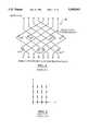
- a Butler-matrix feedSuch a matrix consists of a phasing network with N inputs and N outputs, where N can be any integer number greater than one. This phasing network serves to take each of the N inputs and divide the signal amongst the N output ports with each output port having a fixed phase offset with respect to the other output ports. By properly adjusting the phases between adjacent antennas, the output lobe from the antenna can be electrically steered to the left or fight in a controlled fashion.
- a discussion of the Butler-matrix feedis presented in "Antenna Engineering Handbook", Second Edition, Richard C. Johnsen and Henry Jasick, McGraw-Hill Book Company. pp. 20-56 through 20-60.
- the Butler-matrix feed approachgreatly reduces the problems associated with the visual appearance of a plurality of antennas, with the concomitant reduction in wind loading, as well as some cost savings with regard to mounting space.
- FIG. 2illustrates four sets of four co-linear arrays of radiating elements, yielding a 4 ⁇ 4 panel of radiating elements.
- the beamwidths, sidelobe levels and grating lobes of an antenna comprising N co-linear arrays of N radiating elements driven by an N beam Butler-matrix feedare defined by the physics of the overall antenna system.
- the spacing between the co-linear arrays of radiating elements(in wavelengths of the radiating or received energy) drive the grating lobes while the sidelobes are driven by the spacial Fourier transform of the antenna aperture width and the radiating element spacing within each of the co-linear arrays.
- the sidelobesare approximately 7 dB below the main lobe.
- A-7 dB sidelobeis a significant problem for cellular communications due to the fact that it does not provide the azimuthal beam pattern required for land mobile radio system operation.
- the essence of the present inventionis to decrease the sidelobe levels to below -10 dB by reducing the number of co-linear radiating elements at the outer edges of the multi-co-linear array antenna and to drive the resulting ant Butler-matrix network feed.
- the absolute gain of the antennadecreases slightly because the physical aperture is slightly smaller.
- space taperingThe reduction of the number of co-linear elements for the co-linear arrays toward and at the edges of the antenna is sometimes referred to as space tapering.
- space taperingis highly desirable with regard to the reduction of sidelobe levels. It has been experimentally found that for four co-linear arrays having respectively 2, 4, 4, 2 radiating elements, the sidelobe levels decrease from -7 dB to approximately -12 dB or lower. Such an arrangement results in a 5 dB improvement over that which is achievable with standard 4 ⁇ 4 array antennas and meets the initial requirements of the land mobile radio industry.
- a primary inventive aspect of the present inventionis the use of a microstrip implemented Butler-matrix feed network in combination with an antenna using space tapering in order to achieve a high gain antenna with reduced sidelobe levels which is particularly advantageous for use in land mobile radio applications, including cellular radio communications and PCS communications.
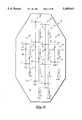
- FIG. 1illustrates a prior art Butler-matrix feed network comprising N inputs and N outputs, where N is equal to 8.
- FIG. 2is a diagrammatic representation of a prior art antenna with four co-linear arrays, in which each co-linear array comprises four radiating elements.
- FIG. 3is a diagrammatic representation of an embodiment of an antenna system according to the present invention, illustrating a space-tapered antenna, comprising four co-linear arrays, wherein the outermost co-linear arrays each have two radiating elements, and wherein the inner arrays each have four radiating elements, a 4-way Butler matrix feed network forming part of the antenna system; and radio receiver(s) and/or transmitter(s) connected to the Butler matrix feed network, the receiver(s) and/or transmitter(s) not forming part of the antenna system.
- FIG. 4is a planar view of a printed circuit board microstrip implementation of the 4-way Butler matrix feed network shown in FIG. 3.
- FIG. 5illustrates the azimuthal electromagnetic radiation (energy) patterns of the four electronically steerable beams that can be generated with the antenna system shown in FIG. 3, wherein the azimuthal patterns of all four beams shown in a composite representation.
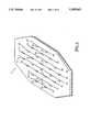
- FIG. 6is a perspective view of a space-tapered antenna for use in an antenna system according to the present invention, the antenna comprising eight co-linear arrays of radiating elements, respectively having 2, 3, 4, 5, 5, 4, 3 and 2 elements per array.
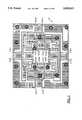
- FIG. 7is a microstrip printed circuit board layout of an 8-way Butler matrix feed network for use with the antenna shown in FIG. 6.
- FIG. 8is the azimuthal composite radiation pattern of an antenna system using the antenna shown in FIG. 6 with a Butler matrix feed network shown in FIG. 7.
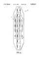
- FIG. 9is a front view of a four co-linear array antenna for use at PCS frequencies.
- FIG. 10is a front view of a four co-linear array antenna that radiates with dual polarization and in which the main lobe azimuthal angles are approximately the same for both polarizations.
- FIG. 11is an illustration of the vertical dipole assembly used for the antenna shown in FIG. 10 as well as for the antennas shown in FIGS. 3, 6 and 9.
- FIG. 12is an illustration of the horizontal dipole assembly used in the dual-polarization antenna shown in FIG. 10.
- the present inventionis directed to an improved antenna system 20 which comprises two major components; namely, a space tapered multi-beam antenna 24 and a Butler-matrix feed network 28.
- the embodiment of the antenna shown in FIG. 3comprises four co-linear arrays 26 of associated electromagnetic radiating elements 30. These radiating elements are typically dipole elements, although other types of radiating element can be used.
- the 4-way Butler matrix feed network 28has four antenna ports 29 and four radio receiver/transmitter ports 31.
- the antenna ports 29are each connected to one co-linear array 26 by cables 35 and connectors 27 associated with each array, while the receiver/transmitter ports 31 are connected to radio receiver and/or radio transmitter equipment 37 by cables 41.
- Cables 35are equal phase cables so as not to introduce any phase change with respect to the signals carried thereover relative to the other cables 35. Cables 41 need not be equal phase cables since any phase changes introduced by these cables is not relevant to the electronic beam(s) being used.
- the radio receiver/transmitter equipmentis shown generally in FIG. 3, since the specific type of equipment used in an actual installation can vary widely.
- the outermost co-linear arrayseach comprise two radiating elements, while the innermost arrays (denoted 1L and 1R) each comprise four radiating elements.
- the spacing between adjacent elements 30 in a co-linear arrayis preferably approximately ⁇ , where ⁇ is the wavelength of the electromagnetic energy to be received or transmitted.
- the spacing between adjacent co-linear arrays, such as between arrays A and B,is typically approximately ⁇ /2 (0.47 ⁇ for the embodiment shown in FIG. 3).
- the Butler-matrix feed network 28has N antenna ports 29 and N receiver/transmitter equipment ports 3l, where N is equal to the number of co-linear arrays of the associated antenna.
- each radiating element 30is, in this preferred embodiment, a dipole radiating element.
- Energyis radiated or received from these dipole elements by means of a feed strap 43 having a centrally located connector 27.
- the dipole elementsare spaced from each adjacent dipole element of the same array by a distance approximately equal to ⁇ .
- the feed strapincludes portions 45 extending beyond the lowermost and uppermost dipole element, with the end of these portions connected to the electrically conductive back plate 47 of the antenna.
- Such a feed strap configurationis known in the art as a Bogner type feed (see U.S. Pat. No. 4,086,598).
- the Butler matrix feed network 28 for use with the antenna shown in FIG. 3is best seen in FIG. 4.
- This implementationuses a planar microstrip design with no crossovers and is fabricated from a printed circuit board 39 having a dielectric substrate made of low loss ceramic material, such as glass epoxy.
- Butler matrix antenna ports 29are designated 2L, 1L, 1R, and 2R, corresponding to their respective connection to co-linear array 2L, 1L, 1R and 2R.
- the receiver/transmitter ports 31are designated 2L, 1L, 1R and 2R.
- Each antenna and receiver/transmitter portcomprises an associated coaxial connector.
- FIG. 5illustrates the radiation pattern generated with the antenna system shown in FIG. 3 for a frequency of 859 MHz (0.859 GHz).
- the radiation patternis a composite showing all four radiation beam patterns generated when the 2L, 1L, 1R and 2R Butler matrix receiver/transmitter ports 31 are respectively used.
- the antennawill have a main lobe 32, designated 2L.
- this main lobehas a beam peak of 3.6 dB at -46.76° and a beamwidth of 33.93°.
- FIG. 6illustrates a second embodiment of an antenna used in an antenna system according to the present invention which comprises eight co-linear arrays 26 identified by the notation 4L, 3L, 2L, 1L, 1R, 2R, 3R and 4R, where the L and R stand for left and right respectively.
- the overall structure of this antennais similar to that for the four co-linear array antenna shown in FIG. 3 but that the number of radiating elements is, from the 4L array to the 4R array, respectively 2, 3, 4, 5, 5, 4, 3,2.
- FIG. 7illustrates the layout of the microstrip printed circuit board implementation of a Butler matrix feed network 28 used for connection with the antenna 24 shown in FIG. 6. Again, this printed circuit board shows no crossovers and is fabricated from a similar material as that shown in FIG. 4.
- the ports 29are identified with the 4L, 3L, 2L, 1L, 1R, 2R, 3R, 4R notation corresponding to the co-linear array connections with the ports 31 for connection to the radio receiver(s) and/or transmitter(s) having a similar notation.
- the resulting main lobes and primary sidelobes of the antenna system using the antennas of FIG. 6 with the Butler matrix feed network of FIG. 7is shown in composite representation in FIG. 8 for an operating frequency of 859 MHz (0.859 GHz).
- antenna 24 shown in FIG. 6is driven by a transmission signal presented at port 31 of the Butler matrix at the 4L location, the main lobe of energy transmission is at main lobe 32-4L.
- the main lobe of the antenna shown in FIG. 6would be directed as shown by main lobe 32-4L if the 4L port 31 is connected to a receiver.
- the electronic steerability of the antenna with respect to the Butler matrix feed networkis similar to that illustrated with regard to the four co-linear array antenna and four-way Butler matrix feed network shown in FIGS. 3-5, except that the beamwidths for the eight co-linear array antenna system, are narrower by approximately one-half. Again, due to the space tapering of the antenna as driven by the Butler matrix feed network, sidelobe levels are significantly less than if the eight co-linear array antenna used the same number of radiating elements for each co-linear array.
- the number of radiating elements for the antenna shown in FIG. 3varies from 2 to 4, back to 2 and for the eight co-linear array antenna shown in FIG. 6, varies from 2 to 5, back to 2, other number of radiating elements can be employed with a corresponding effect on the antenna gain while still maintaining significant sidelobe attenuation as compared to a co-linear array antenna using a fixed number of radiating elements for each co-linear array.
- the number of radiating elements for the four co-linear array antennacould be 1, 2, 2, 1 or 3, 4, 4, 3, or 1, 3, 3, 1, as long as the number of radiating elements toward the side periphery of the antenna is monotonically less than the number of elements toward the middle of the antenna.
- FIG. 9illustrates a four co-linear array antenna similar to that shown in FIG. 3 but specifically designed for operation at personal communication system (PCS) frequencies of the order of 1.8 GHz.
- PCSpersonal communication system
- the number of radiating elements from 2L to 2Rare respectively 4, 8, 8, 4.
- the radiating elements 30are dipoles.
- FIG. 10shows another embodiment of an antenna for use in the present antenna system invention in which the antenna comprises two sets of four co-linear arrays of radiating elements (26 and 26') for operation in both the vertical and horizontal orientations respectively.
- FIG. 10Details of the vertical dipole assembly are shown in FIG. 10 which correspond to the dipole assemblies shown for the antennas illustrated in FIGS. 3, 6 and 9, while the horizontal dipole assembly 30' is shown in FIG. 12. It is there seen that the active side 49 and the passive side 51 of these radiating elements are directed downward toward the back plane 47 of the antenna. The angle of the active and passive sides of the radiating element is approximately 59° as shown by arrow 53.
- this downward angle for the active and passive sides of the horizontal dipole radiating elementsis to achieve an azimuthal steerable angle commensurate with that of the vertical dipole assemblies.
- the arrangement shown in FIGS. 10, 11 and 12achieves an azimuthal steerable angle of approximately 100°, whereas if the horizontal radiating elements were co-linear with respect to each other, the azimuthal steerable angle for the horizontal polarization radiating pattern would be less than 90°.
- an antenna systemwhich incorporates a space tapered antenna design comprising a plurality of co-linear arrays of radiating elements, with the number of radiating elements increasing monotonically from the side periphery of the antenna toward the co-linear arrays at the middle of the antenna, which when driven by or receiving information via a phase array feed network, such as a Butler matrix feed network, is steerable over a wide azimuthal angle so as to obtain significantly improved sidelobe attenuation as compared to antenna systems using a plurality of co-linear arrays of radiating elements with a fixed number of radiating elements per co-linear array.
- a phase array feed networksuch as a Butler matrix feed network
Landscapes
- Variable-Direction Aerials And Aerial Arrays (AREA)
Abstract
Description
TABLE 1 ______________________________________ BEAM PEAK POSITION BEAM WIDTH MAIN LOBE (DEGREES) (DEGREES) ______________________________________ 2 L -46.76 33.93 1 L -15.51 30.27 1 R 15.89 30.06 2 R 47.02 33.47 ______________________________________ DIFFERENCE BETWEEN SIDELOBE BEAM PEAK MAIN LOBE PEAK AND (HIGHEST) POSITION SIDELOBE PEAK ______________________________________ 2 L 71.75 (dB) -11.86 1 L -71.00 (dB) -19.41 1 L 29.00 (dB) -14.61 1 R -29.75 (dB) -12.61 1 R 71.75 (dB) -21.29 2 R -68.25 (dB) -10.68 ______________________________________
Claims (15)
Priority Applications (1)
| Application Number | Priority Date | Filing Date | Title |
|---|---|---|---|
| US08/365,590US5589843A (en) | 1994-12-28 | 1994-12-28 | Antenna system with tapered aperture antenna and microstrip phase shifting feed network |
Applications Claiming Priority (1)
| Application Number | Priority Date | Filing Date | Title |
|---|---|---|---|
| US08/365,590US5589843A (en) | 1994-12-28 | 1994-12-28 | Antenna system with tapered aperture antenna and microstrip phase shifting feed network |
Publications (1)
| Publication Number | Publication Date |
|---|---|
| US5589843Atrue US5589843A (en) | 1996-12-31 |
Family
ID=23439493
Family Applications (1)
| Application Number | Title | Priority Date | Filing Date |
|---|---|---|---|
| US08/365,590Expired - LifetimeUS5589843A (en) | 1994-12-28 | 1994-12-28 | Antenna system with tapered aperture antenna and microstrip phase shifting feed network |
Country Status (1)
| Country | Link |
|---|---|
| US (1) | US5589843A (en) |
Cited By (34)
| Publication number | Priority date | Publication date | Assignee | Title |
|---|---|---|---|---|
| WO1997039494A1 (en)* | 1996-04-12 | 1997-10-23 | Allen Telecom Inc. | Antenna having improved front-to-back ratio |
| EP0855760A3 (en)* | 1997-01-22 | 1998-08-05 | Radio Frequency Systems, Inc | Microstrip collinear antenna |
| US5929823A (en)* | 1997-07-17 | 1999-07-27 | Metawave Communications Corporation | Multiple beam planar array with parasitic elements |
| US5969689A (en)* | 1997-01-13 | 1999-10-19 | Metawave Communications Corporation | Multi-sector pivotal antenna system and method |
| US5982337A (en)* | 1998-02-20 | 1999-11-09 | Marconi Aerospace Systems Inc. | Cellular antennas for stratosphere coverage of multi-band annular earth pattern |
| US6034649A (en)* | 1998-10-14 | 2000-03-07 | Andrew Corporation | Dual polarized based station antenna |
| US6072432A (en)* | 1997-05-02 | 2000-06-06 | Radio Frequency Systems, Inc. | Hybrid power tapered/space tapered multi-beam antenna |
| US6072439A (en)* | 1998-01-15 | 2000-06-06 | Andrew Corporation | Base station antenna for dual polarization |
| WO2000036705A1 (en)* | 1998-12-17 | 2000-06-22 | Metawave Communications Corporation | Dual mode switched beam antenna |
| US6188373B1 (en) | 1996-07-16 | 2001-02-13 | Metawave Communications Corporation | System and method for per beam elevation scanning |
| US6201511B1 (en)* | 1997-04-18 | 2001-03-13 | Ericsson Inc. | Composite antenna for duplexer-free duplex operation terminals and method |
| US6285336B1 (en) | 1999-11-03 | 2001-09-04 | Andrew Corporation | Folded dipole antenna |
| US6317099B1 (en) | 2000-01-10 | 2001-11-13 | Andrew Corporation | Folded dipole antenna |
| US6317100B1 (en)* | 1999-07-12 | 2001-11-13 | Metawave Communications Corporation | Planar antenna array with parasitic elements providing multiple beams of varying widths |
| US6353410B1 (en)* | 1999-03-19 | 2002-03-05 | Radio Frequency Systems, Inc. | Space tapered antenna having compressed spacing or feed network phase progression, or both |
| US6448930B1 (en) | 1999-10-15 | 2002-09-10 | Andrew Corporation | Indoor antenna |
| US6583760B2 (en) | 1998-12-17 | 2003-06-24 | Metawave Communications Corporation | Dual mode switched beam antenna |
| US20030227420A1 (en)* | 2002-06-05 | 2003-12-11 | Andrew Corporation | Integrated aperture and calibration feed for adaptive beamforming systems |
| US6731904B1 (en) | 1999-07-20 | 2004-05-04 | Andrew Corporation | Side-to-side repeater |
| US6885343B2 (en) | 2002-09-26 | 2005-04-26 | Andrew Corporation | Stripline parallel-series-fed proximity-coupled cavity backed patch antenna array |
| US6934511B1 (en) | 1999-07-20 | 2005-08-23 | Andrew Corporation | Integrated repeater |
| WO2006120397A1 (en)* | 2005-05-12 | 2006-11-16 | Qinetiq Limited | Electrically steerable phased array antenna system |
| US20090278759A1 (en)* | 2006-09-11 | 2009-11-12 | Kmw Inc. | Dual-Band Dual-Polarized Base Station Antenna for Mobile Communication |
| US7623868B2 (en) | 2002-09-16 | 2009-11-24 | Andrew Llc | Multi-band wireless access point comprising coextensive coverage regions |
| US20100029197A1 (en)* | 1999-07-20 | 2010-02-04 | Andrew Llc | Repeaters for wireless communication systems |
| US20130038504A1 (en)* | 2011-08-08 | 2013-02-14 | Stanley W. Livingston | Continuous current rod antenna |
| US8558746B2 (en) | 2011-11-16 | 2013-10-15 | Andrew Llc | Flat panel array antenna |
| US8866687B2 (en) | 2011-11-16 | 2014-10-21 | Andrew Llc | Modular feed network |
| US9160049B2 (en) | 2011-11-16 | 2015-10-13 | Commscope Technologies Llc | Antenna adapter |
| US9196950B1 (en) | 2012-12-11 | 2015-11-24 | Siklu Communication ltd. | Systems and methods for vibration amelioration in a millimeter-wave communication network |
| GB2532206A (en)* | 2014-11-06 | 2016-05-18 | Bluwireless Tech Ltd | Antennas |
| WO2017040830A1 (en)* | 2015-09-04 | 2017-03-09 | Elwha Llc | Tunable metamaterial systems and methods |
| EP3758141A1 (en)* | 2019-06-24 | 2020-12-30 | CommScope Technologies LLC | Base station antenna |
| US11641055B2 (en) | 2020-09-01 | 2023-05-02 | Commscope Technologies Llc | Base station antennas having staggered linear arrays with improved phase center alignment between adjacent arrays |
Citations (18)
| Publication number | Priority date | Publication date | Assignee | Title |
|---|---|---|---|---|
| US3474447A (en)* | 1968-05-02 | 1969-10-21 | Raytheon Co | Electronically scanned tacan antenna |
| US3701157A (en)* | 1971-06-03 | 1972-10-24 | Us Air Force | Helicopter uhf antenna system for satellite communications |
| US3836970A (en)* | 1971-06-08 | 1974-09-17 | Siemens Ag | Antenna array for aircraft navigation system |
| US3858218A (en)* | 1973-04-03 | 1974-12-31 | Hazeltine Corp | Antenna system for radiating doppler coded pattern, using sequential modal excitation |
| US3997900A (en)* | 1975-03-12 | 1976-12-14 | The Singer Company | Four beam printed antenna for Doopler application |
| US4032922A (en)* | 1976-01-09 | 1977-06-28 | The United States Of America As Represented By The Secretary Of The Navy | Multibeam adaptive array |
| US4062019A (en)* | 1976-04-02 | 1977-12-06 | Rca Corporation | Low cost linear/circularly polarized antenna |
| US4063243A (en)* | 1975-05-27 | 1977-12-13 | The United States Of America As Represented By The Secretary Of The Navy | Conformal radar antenna |
| US4231040A (en)* | 1978-12-11 | 1980-10-28 | Motorola, Inc. | Simultaneous multiple beam antenna array matrix and method thereof |
| US4316192A (en)* | 1979-11-01 | 1982-02-16 | The Bendix Corporation | Beam forming network for butler matrix fed circular array |
| US4495502A (en)* | 1982-01-27 | 1985-01-22 | The United States Of America As Represented By The Secretary Of The Air Force | Multiple loop sidelobe canceller |
| US4596986A (en)* | 1983-08-29 | 1986-06-24 | The United States Of America As Represented By The Secretary Of The Navy | Sidelobe canceller with adaptive antenna subarraying using a weighted Butler matrix |
| US4633257A (en)* | 1983-11-14 | 1986-12-30 | Sanders Associates, Inc. | Acquisition system employing circular array |
| US4882588A (en)* | 1986-12-22 | 1989-11-21 | Hughes Aircraft Company | Steerable beam antenna system using butler matrix |
| US4905014A (en)* | 1988-04-05 | 1990-02-27 | Malibu Research Associates, Inc. | Microwave phasing structures for electromagnetically emulating reflective surfaces and focusing elements of selected geometry |
| US5115248A (en)* | 1989-09-26 | 1992-05-19 | Agence Spatiale Europeenne | Multibeam antenna feed device |
| US5255004A (en)* | 1991-09-09 | 1993-10-19 | Cubic Defense Systems, Inc. | Linear array dual polarization for roll compensation |
| US5353032A (en)* | 1992-05-05 | 1994-10-04 | Alcatel Italia S.P.A. | Circuit including a phase shifter for generating signals for electronically scanned antennas |
- 1994
- 1994-12-28USUS08/365,590patent/US5589843A/ennot_activeExpired - Lifetime
Patent Citations (18)
| Publication number | Priority date | Publication date | Assignee | Title |
|---|---|---|---|---|
| US3474447A (en)* | 1968-05-02 | 1969-10-21 | Raytheon Co | Electronically scanned tacan antenna |
| US3701157A (en)* | 1971-06-03 | 1972-10-24 | Us Air Force | Helicopter uhf antenna system for satellite communications |
| US3836970A (en)* | 1971-06-08 | 1974-09-17 | Siemens Ag | Antenna array for aircraft navigation system |
| US3858218A (en)* | 1973-04-03 | 1974-12-31 | Hazeltine Corp | Antenna system for radiating doppler coded pattern, using sequential modal excitation |
| US3997900A (en)* | 1975-03-12 | 1976-12-14 | The Singer Company | Four beam printed antenna for Doopler application |
| US4063243A (en)* | 1975-05-27 | 1977-12-13 | The United States Of America As Represented By The Secretary Of The Navy | Conformal radar antenna |
| US4032922A (en)* | 1976-01-09 | 1977-06-28 | The United States Of America As Represented By The Secretary Of The Navy | Multibeam adaptive array |
| US4062019A (en)* | 1976-04-02 | 1977-12-06 | Rca Corporation | Low cost linear/circularly polarized antenna |
| US4231040A (en)* | 1978-12-11 | 1980-10-28 | Motorola, Inc. | Simultaneous multiple beam antenna array matrix and method thereof |
| US4316192A (en)* | 1979-11-01 | 1982-02-16 | The Bendix Corporation | Beam forming network for butler matrix fed circular array |
| US4495502A (en)* | 1982-01-27 | 1985-01-22 | The United States Of America As Represented By The Secretary Of The Air Force | Multiple loop sidelobe canceller |
| US4596986A (en)* | 1983-08-29 | 1986-06-24 | The United States Of America As Represented By The Secretary Of The Navy | Sidelobe canceller with adaptive antenna subarraying using a weighted Butler matrix |
| US4633257A (en)* | 1983-11-14 | 1986-12-30 | Sanders Associates, Inc. | Acquisition system employing circular array |
| US4882588A (en)* | 1986-12-22 | 1989-11-21 | Hughes Aircraft Company | Steerable beam antenna system using butler matrix |
| US4905014A (en)* | 1988-04-05 | 1990-02-27 | Malibu Research Associates, Inc. | Microwave phasing structures for electromagnetically emulating reflective surfaces and focusing elements of selected geometry |
| US5115248A (en)* | 1989-09-26 | 1992-05-19 | Agence Spatiale Europeenne | Multibeam antenna feed device |
| US5255004A (en)* | 1991-09-09 | 1993-10-19 | Cubic Defense Systems, Inc. | Linear array dual polarization for roll compensation |
| US5353032A (en)* | 1992-05-05 | 1994-10-04 | Alcatel Italia S.P.A. | Circuit including a phase shifter for generating signals for electronically scanned antennas |
Cited By (51)
| Publication number | Priority date | Publication date | Assignee | Title |
|---|---|---|---|---|
| WO1997039494A1 (en)* | 1996-04-12 | 1997-10-23 | Allen Telecom Inc. | Antenna having improved front-to-back ratio |
| US6188373B1 (en) | 1996-07-16 | 2001-02-13 | Metawave Communications Corporation | System and method for per beam elevation scanning |
| US5969689A (en)* | 1997-01-13 | 1999-10-19 | Metawave Communications Corporation | Multi-sector pivotal antenna system and method |
| EP0855760A3 (en)* | 1997-01-22 | 1998-08-05 | Radio Frequency Systems, Inc | Microstrip collinear antenna |
| AU740174C (en)* | 1997-01-22 | 2004-05-06 | Radio Frequency Systems Inc. | Antenna having double-sided printed circuit board with collinear, alternating and opposing radiating elements and microstrip transmission line |
| US5963168A (en)* | 1997-01-22 | 1999-10-05 | Radio Frequency Systems, Inc. | Antenna having double-sided printed circuit board with collinear, alternating and opposing radiating elements and microstrip transmission lines |
| AU740174B2 (en)* | 1997-01-22 | 2001-11-01 | Radio Frequency Systems Inc. | Antenna having double-sided printed circuit board with collinear, alternating and opposing radiating elements and microstrip transmission line |
| US6201511B1 (en)* | 1997-04-18 | 2001-03-13 | Ericsson Inc. | Composite antenna for duplexer-free duplex operation terminals and method |
| US6072432A (en)* | 1997-05-02 | 2000-06-06 | Radio Frequency Systems, Inc. | Hybrid power tapered/space tapered multi-beam antenna |
| US5929823A (en)* | 1997-07-17 | 1999-07-27 | Metawave Communications Corporation | Multiple beam planar array with parasitic elements |
| US6072439A (en)* | 1998-01-15 | 2000-06-06 | Andrew Corporation | Base station antenna for dual polarization |
| US5982337A (en)* | 1998-02-20 | 1999-11-09 | Marconi Aerospace Systems Inc. | Cellular antennas for stratosphere coverage of multi-band annular earth pattern |
| US6034649A (en)* | 1998-10-14 | 2000-03-07 | Andrew Corporation | Dual polarized based station antenna |
| WO2000036705A1 (en)* | 1998-12-17 | 2000-06-22 | Metawave Communications Corporation | Dual mode switched beam antenna |
| US6198434B1 (en) | 1998-12-17 | 2001-03-06 | Metawave Communications Corporation | Dual mode switched beam antenna |
| US6583760B2 (en) | 1998-12-17 | 2003-06-24 | Metawave Communications Corporation | Dual mode switched beam antenna |
| US6353410B1 (en)* | 1999-03-19 | 2002-03-05 | Radio Frequency Systems, Inc. | Space tapered antenna having compressed spacing or feed network phase progression, or both |
| US6317100B1 (en)* | 1999-07-12 | 2001-11-13 | Metawave Communications Corporation | Planar antenna array with parasitic elements providing multiple beams of varying widths |
| US6745003B1 (en) | 1999-07-20 | 2004-06-01 | Andrew Corporation | Adaptive cancellation for wireless repeaters |
| US8971796B2 (en) | 1999-07-20 | 2015-03-03 | Andrew Llc | Repeaters for wireless communication systems |
| US20100029197A1 (en)* | 1999-07-20 | 2010-02-04 | Andrew Llc | Repeaters for wireless communication systems |
| US8358970B2 (en) | 1999-07-20 | 2013-01-22 | Andrew Corporation | Repeaters for wireless communication systems |
| US6731904B1 (en) | 1999-07-20 | 2004-05-04 | Andrew Corporation | Side-to-side repeater |
| US8630581B2 (en) | 1999-07-20 | 2014-01-14 | Andrew Llc | Repeaters for wireless communication systems |
| US8010042B2 (en) | 1999-07-20 | 2011-08-30 | Andrew Llc | Repeaters for wireless communication systems |
| US6934511B1 (en) | 1999-07-20 | 2005-08-23 | Andrew Corporation | Integrated repeater |
| US6448930B1 (en) | 1999-10-15 | 2002-09-10 | Andrew Corporation | Indoor antenna |
| US6285336B1 (en) | 1999-11-03 | 2001-09-04 | Andrew Corporation | Folded dipole antenna |
| US6317099B1 (en) | 2000-01-10 | 2001-11-13 | Andrew Corporation | Folded dipole antenna |
| WO2003019717A3 (en)* | 2001-08-23 | 2003-09-18 | Metawave Comm Corp | Dual mode switched beam antenna |
| US20030227420A1 (en)* | 2002-06-05 | 2003-12-11 | Andrew Corporation | Integrated aperture and calibration feed for adaptive beamforming systems |
| US7623868B2 (en) | 2002-09-16 | 2009-11-24 | Andrew Llc | Multi-band wireless access point comprising coextensive coverage regions |
| US6885343B2 (en) | 2002-09-26 | 2005-04-26 | Andrew Corporation | Stripline parallel-series-fed proximity-coupled cavity backed patch antenna array |
| WO2006120397A1 (en)* | 2005-05-12 | 2006-11-16 | Qinetiq Limited | Electrically steerable phased array antenna system |
| US20080191940A1 (en)* | 2005-05-12 | 2008-08-14 | Qinetiq Limited | Electrically Steerable Phased Array Antenna System |
| US7609205B2 (en) | 2005-05-12 | 2009-10-27 | Qinetiq Limited | Electrically steerable phased array antenna system |
| US20090278759A1 (en)* | 2006-09-11 | 2009-11-12 | Kmw Inc. | Dual-Band Dual-Polarized Base Station Antenna for Mobile Communication |
| US8199063B2 (en)* | 2006-09-11 | 2012-06-12 | Kmw Inc. | Dual-band dual-polarized base station antenna for mobile communication |
| US20130038504A1 (en)* | 2011-08-08 | 2013-02-14 | Stanley W. Livingston | Continuous current rod antenna |
| US8665173B2 (en)* | 2011-08-08 | 2014-03-04 | Raytheon Company | Continuous current rod antenna |
| US9160049B2 (en) | 2011-11-16 | 2015-10-13 | Commscope Technologies Llc | Antenna adapter |
| US8866687B2 (en) | 2011-11-16 | 2014-10-21 | Andrew Llc | Modular feed network |
| US8558746B2 (en) | 2011-11-16 | 2013-10-15 | Andrew Llc | Flat panel array antenna |
| US9196950B1 (en) | 2012-12-11 | 2015-11-24 | Siklu Communication ltd. | Systems and methods for vibration amelioration in a millimeter-wave communication network |
| GB2532206A (en)* | 2014-11-06 | 2016-05-18 | Bluwireless Tech Ltd | Antennas |
| WO2017040830A1 (en)* | 2015-09-04 | 2017-03-09 | Elwha Llc | Tunable metamaterial systems and methods |
| EP3758141A1 (en)* | 2019-06-24 | 2020-12-30 | CommScope Technologies LLC | Base station antenna |
| US11108169B2 (en) | 2019-06-24 | 2021-08-31 | Commscope Technologies Llc | Base station antenna |
| US11600931B2 (en) | 2019-06-24 | 2023-03-07 | Commscope Technologies Llc | Base station antenna |
| US11641055B2 (en) | 2020-09-01 | 2023-05-02 | Commscope Technologies Llc | Base station antennas having staggered linear arrays with improved phase center alignment between adjacent arrays |
| US11909103B2 (en) | 2020-09-01 | 2024-02-20 | Commscope Technologies Llc | Base station antennas having staggered linear arrays with improved phase center alignment between adjacent arrays |
Similar Documents
| Publication | Publication Date | Title |
|---|---|---|
| US5589843A (en) | Antenna system with tapered aperture antenna and microstrip phase shifting feed network | |
| US11917427B2 (en) | Multi-beam base station antennas having wideband radiating elements | |
| US12261373B2 (en) | Dual-beam sector antenna and array | |
| US11670865B2 (en) | Butler-based quasi-omni MIMO antenna | |
| US8237619B2 (en) | Dual beam sector antenna array with low loss beam forming network | |
| US11990669B2 (en) | Base station antennas having arrays of radiating elements with 4 ports without usage of diplexers | |
| US7212163B2 (en) | Circular polarized array antenna | |
| US9761937B2 (en) | Fragmented aperture for the Ka/K/Ku frequency bands | |
| CN112332111B (en) | Double circular polarization expandable active subarray | |
| KR20070088696A (en) | Antenna device and related method | |
| WO2002041450A1 (en) | Dual-beam antenna aperture | |
| US11563271B2 (en) | Antenna array with ABFN circuitry | |
| US6072432A (en) | Hybrid power tapered/space tapered multi-beam antenna | |
| CN109273870B (en) | Broadband six-beam array antenna | |
| US12327923B2 (en) | Mixed element beam forming antenna | |
| EP2290744B1 (en) | Closed shape beam forming network | |
| US6353410B1 (en) | Space tapered antenna having compressed spacing or feed network phase progression, or both | |
| US20240128638A1 (en) | Twin-beam antennas having hybrid couplers | |
| US12199703B2 (en) | Sector-splitting multi-beam base station antennas having multiple beamforming networks per polarization | |
| Dominguez et al. | Multi-Beam Electronically Steerable Antenna Array concepts for an X-Band Deep Space Gateway Data Link | |
| Kelly et al. | Microstrip Array for Troposcatter Communications |
Legal Events
| Date | Code | Title | Description |
|---|---|---|---|
| AS | Assignment | Owner name:RADIO FREQUENCY SYSTEMS, INC., NEW JERSEY Free format text:ASSIGNMENT OF ASSIGNORS INTEREST;ASSIGNORS:MEREDITH, SHELDON K.;GAUKEL, KEVIN J.;ARNOLD, PITT W.;REEL/FRAME:007383/0252 Effective date:19950220 Owner name:RADIO FREQUENCY SYSTEMS, INC., NEW JERSEY Free format text:ASSIGNMENT OF ASSIGNORS INTEREST;ASSIGNORS:HUNT, WARREN F.;CONNOLLY, KEVIN J.;REEL/FRAME:007383/0248 Effective date:19950214 | |
| STCF | Information on status: patent grant | Free format text:PATENTED CASE | |
| FEPP | Fee payment procedure | Free format text:PAYOR NUMBER ASSIGNED (ORIGINAL EVENT CODE: ASPN); ENTITY STATUS OF PATENT OWNER: LARGE ENTITY | |
| FPAY | Fee payment | Year of fee payment:4 | |
| FPAY | Fee payment | Year of fee payment:8 | |
| AS | Assignment | Owner name:RADIO FREQUENCY SYSTEMS, INC., CONNECTICUT Free format text:MERGER AND NAME CHANGE;ASSIGNORS:RADIO FREQUENCY SYSTEMS, INC.;ALCATEL NA CABLE SYSTEMS, INC.;REEL/FRAME:015370/0553 Effective date:20040624 | |
| FPAY | Fee payment | Year of fee payment:12 | |
| AS | Assignment | Owner name:CREDIT SUISSE AG, NEW YORK Free format text:SECURITY AGREEMENT;ASSIGNOR:LUCENT, ALCATEL;REEL/FRAME:029821/0001 Effective date:20130130 Owner name:CREDIT SUISSE AG, NEW YORK Free format text:SECURITY AGREEMENT;ASSIGNOR:ALCATEL LUCENT;REEL/FRAME:029821/0001 Effective date:20130130 | |
| AS | Assignment | Owner name:ALCATEL LUCENT, FRANCE Free format text:RELEASE BY SECURED PARTY;ASSIGNOR:CREDIT SUISSE AG;REEL/FRAME:033868/0001 Effective date:20140819 |