US5589666A - Enclosure for sealing a splice of electrical cables - Google Patents
Enclosure for sealing a splice of electrical cablesDownload PDFInfo
- Publication number
- US5589666A US5589666AUS08/055,494US5549493AUS5589666AUS 5589666 AUS5589666 AUS 5589666AUS 5549493 AUS5549493 AUS 5549493AUS 5589666 AUS5589666 AUS 5589666A
- Authority
- US
- United States
- Prior art keywords
- closure
- enclosure according
- sealing
- interior space
- encapsulant
- Prior art date
- Legal status (The legal status is an assumption and is not a legal conclusion. Google has not performed a legal analysis and makes no representation as to the accuracy of the status listed.)
- Expired - Lifetime
Links
Images

Classifications
- H—ELECTRICITY
- H02—GENERATION; CONVERSION OR DISTRIBUTION OF ELECTRIC POWER
- H02G—INSTALLATION OF ELECTRIC CABLES OR LINES, OR OF COMBINED OPTICAL AND ELECTRIC CABLES OR LINES
- H02G1/00—Methods or apparatus specially adapted for installing, maintaining, repairing or dismantling electric cables or lines
- H02G1/14—Methods or apparatus specially adapted for installing, maintaining, repairing or dismantling electric cables or lines for joining or terminating cables
- H—ELECTRICITY
- H02—GENERATION; CONVERSION OR DISTRIBUTION OF ELECTRIC POWER
- H02G—INSTALLATION OF ELECTRIC CABLES OR LINES, OR OF COMBINED OPTICAL AND ELECTRIC CABLES OR LINES
- H02G15/00—Cable fittings
- H02G15/013—Sealing means for cable inlets
- H—ELECTRICITY
- H02—GENERATION; CONVERSION OR DISTRIBUTION OF ELECTRIC POWER
- H02G—INSTALLATION OF ELECTRIC CABLES OR LINES, OR OF COMBINED OPTICAL AND ELECTRIC CABLES OR LINES
- H02G15/00—Cable fittings
- H02G15/08—Cable junctions
- H02G15/10—Cable junctions protected by boxes, e.g. by distribution, connection or junction boxes
- H02G15/113—Boxes split longitudinally in main cable direction
Definitions
- This inventionrelates generally to a cable splice enclosure for protecting a splice of electrical cables and more particularly to telecommunications cables.
- the splice areais generally contained within a protective housing known as an enclosure.
- the protective enclosuresare commonly referred to as buried service drop enclosures.
- Such buried enclosuresnot only must be formed of materials to provide structural rigidity and strength for use underground, but must also protect the splices from the ingress of moisture.
- an enclosure for sealing a splice of electrical cablescomprises a closure defining an interior space for accommodating a splice of cables and defining an opening for receipt of the splice therethrough.
- a closure sealis provided for sealably closing the closure opening and having apertures for receipt therethrough of the cables.
- Meansare provided for sealing the closure seal to the closure and for sealing the cables to the closure seal at the apertures.
- An inlet fittingextends into and communicates with the interior space, the inlet fitting adapted to receive and pass an encapsulant under pressure therethrough into the interior space.
- An outlet fittingextends into and communicates with the interior space, the outlet fitting adapted to pass the encapsulant therethrough when the encapsulant is exposed to a predetermined pressure in said interior space.
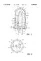
- FIG 1.is a cross-sectional view of a splice enclosure in accordance with a preferred embodiment of the invention.
- FIG 2.is a bottom view of the enclosure of FIG. 1.
- FIG. 3is a cross-section of a fragmentary portion of the upper end of a splice enclosure showing a particular arrangement of a pressure relief valve for use therewith.
- FIG. 1a buried service drop enclosure 10 for sealing a splice of telecommunication cables 11 and 12, in accordance with a preferred arrangement of the invention.
- Cables 11 and 12typically contain insulated, multiple conductors 11a and 12a that are spliced together by a conventional splice connector 14.
- the enclosure 10is preferably of the type to be utilized underground and, not to be reused or reentered, thereby simplifying the structural complexity over known, reenterable sealing devices.
- the enclosure 10comprises a closure 16 of generally cylindrical shape configuration, closed at its top end except for a vent port 18 and defining at its lower end an opening 20. Opening 20 is preferably substantially circular.
- the closure 16thereby defines an interior space 22 for accommodating the spliced cables 11a and 12a.
- the closure 16is a unitary, integral member molded of plastic material, preferably a high density polyethylene, although other materials may be used, taken into consideration the desirable strength desirable for underground purposes.
- a closure seal 24is adapted to be received in the bottom of the closure 16 and to sealably close the opening 20.
- Closure seal 24is preferably formed in cylindrical disc shape to fit into the substantially circular opening in the bottom of the closure 16.
- the discis molded of a plastic material, preferably polypropylene.
- Closure seal 24has apertures 26 and 28, respectively configured to accommodate the telecommunication cables 11 and 12. As can be seen in FIG. 2, apertures 26 and 28 may be formed of different dimensions to accommodate different sizes of telecommunications cables 11 and 12. Further, the apertures 26 and 28 are preferably formed to extend radially into the closure seal 24 in a manner that permits entry of the cables 11 and 12 radially as well as axially. Further, although two cables 11 and 12 with corresponding apertures 26 and 28 are shown, it should be appreciated that any number of cables and apertures may be used, depending upon the desired number of splices to be made.
- the cables 11 and 12are suitably sealed at the apertures 26 and 28 by applying a quantity of sealant, preferably in the form of a butyl mastic tape 30 placed around the outer jacket of the cables 11 and 12 and against the closure seal 24, in a manner as more fully described in commonly assigned, U.S. patent application Ser. No. 07/776,139, filed on Oct. 15, 1991, the disclosure of which is herein incorporated by reference for all purposes.
- a seal 32 or gasket of suitable sealing materialis wrapped around the circumference of closure seal 24 prior to the insertion of the seal 24 into the enclosure opening 20.
- Seal 32may be formed of sealing material, such as butyl mastic, rubber or other elastomeric materials. Once on the closure seal 24, the seal 32 is disposed between the periphery of the closure seal 24 and the inner walls defining the enclosure opening 20.
- clamp 34Disposed at the bottom of the closure 16 and adjacent the closure seal 24 is a clamp 34 that may be received in a groove or recess 36 formed at the lower end of the closure 16.
- Clamp 34is adapted to provide pressure for compressing the seal 32 between the bottom of the closure 16 and the closure seal 24 in order to provide a moisture sealed joint.
- the clamp 34comprises a cable tie, such as that sold under the trademark TY-RAP®, marketed by the assignee of the subject invention, although other types of clamps may be utilized.
- Fitting 38supportsed by the closure seal 24, and preferably molded therein, is an inlet fitting 38.
- Fitting 38includes an inlet port 38a that extends through the closure seal 24 and communicates with the closure interior space 22.
- Inlet fitting 38may be a conventional check valve that allows entry of an encapsulant, but as the encapsulant pressure increases internally in space 22, the valve closes, thereby preventing backflow of encapsulant out through the valve.
- the back pressure in the valve in the preferred arrangementis selected to be approximately 5 psig.
- Outlet fitting 40At the upper end of the enclosure 10 at vent port 18, and preferably molded therein, is an outlet fitting 40. Vent port 18 and thereby outlet fitting 40 extends into and communicates with the interior space 22 of the closure 16. Outlet fitting 40 may be a conventional pressure relief valve that may be preset by the manufacturer to open to provide pressure relief at a predetermined pressure. For the particular use described herein, it has been determined that a pressure of approximately 15 psig is sufficient to provide the desired sealing effect. Of course, different pressures and pressure ranges for different applications may also be contemplated. In the present application, the pressure relief valves are preset at a pressure of about 15 psig.
- a strain relief support 41is provided to form a strain relief member in cooperation with a clamp 43 as illustrated in FIG. 1.
- the strain relief support 41is formed integrally with the closure seal 24 during molding thereof, although a separate strain relief support member 41 may be used.
- the strain relief support 41has an interior opening 41a communicating with the inlet port 38a for passage therethrough of the encapsulant 42.
- the strain relief support 41is formed preferably to have recesses or seats for supporting the cables 11 and 12 therein and against which the cables are secured by means of the clamp 43.
- Clamp 43is preferably a cable tie, although other clamping devices may be utilized.
- the strain reliefis more particularly described with reference to commonly assigned U.S. patent application Ser. No. 07/776,139, filed Oct. 15, 1991 the disclosure of which is incorporated herein for all purposes.
- a suitable encapsulant 42may then be pumped under pressure into the closure interior space 22 through the inlet fitting 38 to ultimately provide a sealed enclosure splice.
- the encapsulantmay comprise polyurethane which is pumped in fluid form from an external pump suitably attached to the inlet fitting 38.
- Such encapsulant and pumpare more particularly described in commonly assigned U.S. patent application Ser. No. 07/776,139, filed Oct. 15, 1991, the disclosure of which is incorporated herein for all purposes.
- any trapped air, as well as the entering encapsulant,are introduced within the enclosure under such pressure.
- the pressure relief valve 40opens, thereby allowing any trapped air to initially escape.
- the fluid encapsulantis continued to be pumped under pressure into the interior space 22.
- encapsulantsporadically escapes from the valve 40 until a steady stream of encapsulant flows therefrom.
- the encapsulantis considered sufficiently pressurized to be forced around the cables, into the interstitial openings between the cables, and around any connections in the splice. This thus creates a barrier against water migration throughout the interstices along the cable conductors.
- FIG. 3another, particular form of pressure relief valve is illustrated and described.
- a deflectable spring member 44is suitably mounted adjacent the port 18.
- the deflectable spring member 44is mounted in cantilevered fashion.
- a shut-off plug 46formed of a resilient material such as rubber, suitably secured and supported thereat.
- spring member 44is supported on a stanchion or boss 48 which may be molded integrally with the closure 16, the spring member 44 being held thereon by a cover 50 which may be suitably attached to the boss 48 by a threaded fastener 52.
- An inner edge 50a of the cover 50defines a fulcrum point against which the spring member 44 is deflected when moved upwardly, as will be described.
- the spring member 44comprises a generally flat strip of metal, having a rectangular cross-section. Such strip may be formed of 0.015 inch thick 1050 blued spring steel, although other suitable materials and configurations may be utilized.
- the spring member 44is mounted in a manner to provide a predetermined bias force to the plug 46, thereby compressing the resilient rubber material of the plug 46 and normally closing the vent port 18.
- the spring member 44is configured to upwardly deflect when the encapsulant 42 in the interior space 22 reaches the predetermined pressure (for example, 15 psig).
- the force of the encapsulant applied to the plug 46is sufficient to overcome the bias force on the plug 46, thereby separating the plug 46 from the vent port 18 and opening the vent port 18 for passage therethrough of the encapsulant 42 at the predetermined pressure.
- the following parametersare to be taken into consideration: the length of the spring member L (i.e., the distance between the fulcrum point 50a and the center of the vent port 18); the cross-sectional area of the spring member 44; and the type of material of the spring member 44 (so that the modulus of elasticity may be determined).
Landscapes
- Cable Accessories (AREA)
Abstract
Description
Claims (19)
Priority Applications (2)
| Application Number | Priority Date | Filing Date | Title |
|---|---|---|---|
| US08/055,494US5589666A (en) | 1991-10-15 | 1993-04-30 | Enclosure for sealing a splice of electrical cables |
| CA 2122543CA2122543A1 (en) | 1993-04-30 | 1994-04-29 | Enclosure for sealing a splice of electrical cables |
Applications Claiming Priority (2)
| Application Number | Priority Date | Filing Date | Title |
|---|---|---|---|
| US07/776,139US5251373A (en) | 1991-10-15 | 1991-10-15 | Method for protection of cable splices |
| US08/055,494US5589666A (en) | 1991-10-15 | 1993-04-30 | Enclosure for sealing a splice of electrical cables |
Related Parent Applications (1)
| Application Number | Title | Priority Date | Filing Date |
|---|---|---|---|
| US07/776,139Continuation-In-PartUS5251373A (en) | 1991-10-15 | 1991-10-15 | Method for protection of cable splices |
Publications (1)
| Publication Number | Publication Date |
|---|---|
| US5589666Atrue US5589666A (en) | 1996-12-31 |
Family
ID=46202193
Family Applications (1)
| Application Number | Title | Priority Date | Filing Date |
|---|---|---|---|
| US08/055,494Expired - LifetimeUS5589666A (en) | 1991-10-15 | 1993-04-30 | Enclosure for sealing a splice of electrical cables |
Country Status (1)
| Country | Link |
|---|---|
| US (1) | US5589666A (en) |
Cited By (19)
| Publication number | Priority date | Publication date | Assignee | Title |
|---|---|---|---|---|
| US6160222A (en)* | 1996-11-25 | 2000-12-12 | Cables Pirelli | Cable connection protecting device |
| US6239372B1 (en)* | 1997-05-27 | 2001-05-29 | Robert Bosch Gmbh | Electrical connection of a movably disposed electrical component with a flexible, elastic conductor track carrier |
| US6329601B1 (en)* | 1996-06-17 | 2001-12-11 | David L. Bulford | Service wire splice housing |
| US6359226B1 (en)* | 1998-04-21 | 2002-03-19 | Tyco Electronics Corporation | Device and method for protecting and sealing exposed wires |
| US20050178003A1 (en)* | 2004-02-18 | 2005-08-18 | Yazaki Corporation | Method of waterproof of electric cable joint |
| US20060048965A1 (en)* | 2004-09-09 | 2006-03-09 | Sumitomo Wiring Systems, Ltd. | Method and structure for waterproofing a terminal splice |
| US7229325B1 (en) | 2005-07-29 | 2007-06-12 | Ilsco Corporation | Submersible electrical connector |
| US20070190839A1 (en)* | 2006-01-18 | 2007-08-16 | Jonli Odd M | Cable end joint assembly |
| US20090176416A1 (en)* | 2006-07-25 | 2009-07-09 | Ilsco Corporation | Submersible electrical connector |
| US7798829B2 (en) | 2008-04-11 | 2010-09-21 | Thomas & Betts International, Inc. | Basic insulating plug and method of manufacture |
| US20120261186A1 (en)* | 2009-11-25 | 2012-10-18 | Autonetworks Technologies, Ltd. | Method for producing wiring harness, and wiring harness |
| WO2013048823A1 (en)* | 2011-09-28 | 2013-04-04 | 3M Innovative Properties Company | Cell tower enclosure |
| EP2712042A1 (en)* | 2012-09-24 | 2014-03-26 | Nexans | Waterproof connector for electric conductors |
| USD740760S1 (en)* | 2014-08-06 | 2015-10-13 | Michael Gene Gliksman | Braided electrical speaker cable |
| US9698518B1 (en)* | 2014-02-27 | 2017-07-04 | The Patent Store Llc | Wire connectors and wire connector kits |
| US20170314692A1 (en)* | 2016-04-28 | 2017-11-02 | Novinium, Inc. | Injection electrical connector |
| US20170346270A1 (en)* | 2014-12-19 | 2017-11-30 | Sumitomo Wining Systems, Ltd. | Protecting cap for terminal consolidation splice |
| US11183791B2 (en)* | 2018-03-30 | 2021-11-23 | Autonetworks Technologies, Ltd. | Wire harness with elastic tube |
| US11374343B2 (en)* | 2018-05-31 | 2022-06-28 | Hydra-Electric Company | Method of preventing moisture intrusion through the cable exit of an enclosure comprising terminals |
Citations (24)
| Publication number | Priority date | Publication date | Assignee | Title |
|---|---|---|---|---|
| FR1256676A (en)* | 1960-02-12 | 1961-03-24 | Die casting refinements | |
| DE7110096U (en)* | 1971-03-17 | 1971-06-16 | Felten & Guilleaume Kabelwerke Ag | Long-split cable sleeve, especially for communication cables |
| US3728467A (en)* | 1971-11-09 | 1973-04-17 | Reliable Electric Co | Buried-type splice case |
| US3806630A (en)* | 1972-08-21 | 1974-04-23 | J Thompson | Encapsulated splice assembly for buried cables |
| DE2319956A1 (en)* | 1973-04-19 | 1974-11-07 | Licentia Gmbh | MULTIPART, PRESSURE-RESISTANT SOCKET |
| US3848074A (en)* | 1973-04-13 | 1974-11-12 | W Channell | Terminal and splice enclosure for cable installations |
| US3939882A (en)* | 1974-02-25 | 1976-02-24 | John T. Thompson | Cable reclamation method and apparatus |
| US4025717A (en)* | 1975-05-07 | 1977-05-24 | Whittingham William F | High voltage shielded cable splice |
| US4053704A (en)* | 1972-11-17 | 1977-10-11 | Smith-Schreyer & Assoc., Inc. | Plug and kit of parts including same for use in forming a moisture-proof cable splice enclosure |
| FR2388432A1 (en)* | 1977-10-12 | 1978-11-17 | Raychem Sa Nv | PROTECTION ASSEMBLY FOR A JUNCTION BETWEEN CONDUITS |
| US4226651A (en)* | 1978-02-01 | 1980-10-07 | Gold Marvin H | High voltage cable splicing - additive reaction |
| GB2067364A (en)* | 1979-12-26 | 1981-07-22 | Preformed Line Products Co | Cable splice enclosure |
| US4341922A (en)* | 1979-07-18 | 1982-07-27 | Minnesota Mining And Manufacturing Company | Strain-relief brace for cable splice case |
| US4490315A (en)* | 1982-02-04 | 1984-12-25 | Northern Telecom Limited | Methods of moulding of plastics articles |
| US4538021A (en)* | 1984-04-06 | 1985-08-27 | At&T Bell Laboratories, Inc. | Cable closure having asymmetrical end plate assembly |
| US4734543A (en)* | 1978-01-09 | 1988-03-29 | Nolf Jean Marie E | Branch-off assembly |
| EP0316911A2 (en)* | 1987-11-18 | 1989-05-24 | Nippon Telegraph And Telephone Corporation | Cable closure |
| US4902855A (en)* | 1988-10-25 | 1990-02-20 | Minnesota Mining And Manufacturing Company | End seal for splice closure |
| WO1990005401A1 (en)* | 1988-11-09 | 1990-05-17 | N.V. Raychem S.A. | Closure assembly |
| US4982054A (en)* | 1988-10-06 | 1991-01-01 | Raychem Corporation | Telecommunications pedestal closure with environmental control liner |
| US5245133A (en)* | 1991-10-15 | 1993-09-14 | Thomas & Betts Corporation | Moisture-resistant cable splice and sealing structure thereof |
| US5251373A (en)* | 1991-10-15 | 1993-10-12 | Thomas & Betts Corporation | Method for protection of cable splices |
| US5308923A (en)* | 1992-06-16 | 1994-05-03 | Raychem Corporation | Enclosure assembly for telecommunication cables |
| US5331114A (en)* | 1991-10-17 | 1994-07-19 | Howard W. Rudolph | Method and apparatus to pressure seal cable splices |
- 1993
- 1993-04-30USUS08/055,494patent/US5589666A/ennot_activeExpired - Lifetime
Patent Citations (25)
| Publication number | Priority date | Publication date | Assignee | Title |
|---|---|---|---|---|
| FR1256676A (en)* | 1960-02-12 | 1961-03-24 | Die casting refinements | |
| DE7110096U (en)* | 1971-03-17 | 1971-06-16 | Felten & Guilleaume Kabelwerke Ag | Long-split cable sleeve, especially for communication cables |
| US3728467A (en)* | 1971-11-09 | 1973-04-17 | Reliable Electric Co | Buried-type splice case |
| US3806630A (en)* | 1972-08-21 | 1974-04-23 | J Thompson | Encapsulated splice assembly for buried cables |
| US4053704A (en)* | 1972-11-17 | 1977-10-11 | Smith-Schreyer & Assoc., Inc. | Plug and kit of parts including same for use in forming a moisture-proof cable splice enclosure |
| US3848074A (en)* | 1973-04-13 | 1974-11-12 | W Channell | Terminal and splice enclosure for cable installations |
| DE2319956A1 (en)* | 1973-04-19 | 1974-11-07 | Licentia Gmbh | MULTIPART, PRESSURE-RESISTANT SOCKET |
| US3939882A (en)* | 1974-02-25 | 1976-02-24 | John T. Thompson | Cable reclamation method and apparatus |
| US4025717A (en)* | 1975-05-07 | 1977-05-24 | Whittingham William F | High voltage shielded cable splice |
| US4421945A (en)* | 1977-04-21 | 1983-12-20 | N.V. Raychem S.A. | Junction assembly |
| FR2388432A1 (en)* | 1977-10-12 | 1978-11-17 | Raychem Sa Nv | PROTECTION ASSEMBLY FOR A JUNCTION BETWEEN CONDUITS |
| US4734543A (en)* | 1978-01-09 | 1988-03-29 | Nolf Jean Marie E | Branch-off assembly |
| US4226651A (en)* | 1978-02-01 | 1980-10-07 | Gold Marvin H | High voltage cable splicing - additive reaction |
| US4341922A (en)* | 1979-07-18 | 1982-07-27 | Minnesota Mining And Manufacturing Company | Strain-relief brace for cable splice case |
| GB2067364A (en)* | 1979-12-26 | 1981-07-22 | Preformed Line Products Co | Cable splice enclosure |
| US4490315A (en)* | 1982-02-04 | 1984-12-25 | Northern Telecom Limited | Methods of moulding of plastics articles |
| US4538021A (en)* | 1984-04-06 | 1985-08-27 | At&T Bell Laboratories, Inc. | Cable closure having asymmetrical end plate assembly |
| EP0316911A2 (en)* | 1987-11-18 | 1989-05-24 | Nippon Telegraph And Telephone Corporation | Cable closure |
| US4982054A (en)* | 1988-10-06 | 1991-01-01 | Raychem Corporation | Telecommunications pedestal closure with environmental control liner |
| US4902855A (en)* | 1988-10-25 | 1990-02-20 | Minnesota Mining And Manufacturing Company | End seal for splice closure |
| WO1990005401A1 (en)* | 1988-11-09 | 1990-05-17 | N.V. Raychem S.A. | Closure assembly |
| US5245133A (en)* | 1991-10-15 | 1993-09-14 | Thomas & Betts Corporation | Moisture-resistant cable splice and sealing structure thereof |
| US5251373A (en)* | 1991-10-15 | 1993-10-12 | Thomas & Betts Corporation | Method for protection of cable splices |
| US5331114A (en)* | 1991-10-17 | 1994-07-19 | Howard W. Rudolph | Method and apparatus to pressure seal cable splices |
| US5308923A (en)* | 1992-06-16 | 1994-05-03 | Raychem Corporation | Enclosure assembly for telecommunication cables |
Non-Patent Citations (2)
| Title |
|---|
| Derwent Publication AN 89 361646 Describing JP 1272429, Oct. 31, 1989.* |
| Derwent Publication AN 89-361646 Describing JP 1272429, Oct. 31, 1989. |
Cited By (31)
| Publication number | Priority date | Publication date | Assignee | Title |
|---|---|---|---|---|
| US6329601B1 (en)* | 1996-06-17 | 2001-12-11 | David L. Bulford | Service wire splice housing |
| US6160222A (en)* | 1996-11-25 | 2000-12-12 | Cables Pirelli | Cable connection protecting device |
| US6239372B1 (en)* | 1997-05-27 | 2001-05-29 | Robert Bosch Gmbh | Electrical connection of a movably disposed electrical component with a flexible, elastic conductor track carrier |
| US6359226B1 (en)* | 1998-04-21 | 2002-03-19 | Tyco Electronics Corporation | Device and method for protecting and sealing exposed wires |
| US7299548B2 (en)* | 2004-02-18 | 2007-11-27 | Yazaki Corporation | Method of waterproof of electric cable joint |
| US20050178003A1 (en)* | 2004-02-18 | 2005-08-18 | Yazaki Corporation | Method of waterproof of electric cable joint |
| US20060048965A1 (en)* | 2004-09-09 | 2006-03-09 | Sumitomo Wiring Systems, Ltd. | Method and structure for waterproofing a terminal splice |
| US7834268B2 (en)* | 2004-09-09 | 2010-11-16 | Sumitomo Wiring Systems, Ltd. | Method and structure for waterproofing a terminal splice |
| US7229325B1 (en) | 2005-07-29 | 2007-06-12 | Ilsco Corporation | Submersible electrical connector |
| US20070190839A1 (en)* | 2006-01-18 | 2007-08-16 | Jonli Odd M | Cable end joint assembly |
| US7955108B2 (en)* | 2006-01-18 | 2011-06-07 | Nexans | Cable end joint assembly |
| US20090176416A1 (en)* | 2006-07-25 | 2009-07-09 | Ilsco Corporation | Submersible electrical connector |
| US7625252B2 (en) | 2006-07-25 | 2009-12-01 | Ilsco Corporation | Submersible electrical connector |
| US7798829B2 (en) | 2008-04-11 | 2010-09-21 | Thomas & Betts International, Inc. | Basic insulating plug and method of manufacture |
| US20120261186A1 (en)* | 2009-11-25 | 2012-10-18 | Autonetworks Technologies, Ltd. | Method for producing wiring harness, and wiring harness |
| US9054434B2 (en)* | 2009-11-25 | 2015-06-09 | Autonetworks Technologies, Ltd. | Method for producing wiring harness, and wiring harness |
| WO2013048823A1 (en)* | 2011-09-28 | 2013-04-04 | 3M Innovative Properties Company | Cell tower enclosure |
| EP2712042A1 (en)* | 2012-09-24 | 2014-03-26 | Nexans | Waterproof connector for electric conductors |
| US9698518B1 (en)* | 2014-02-27 | 2017-07-04 | The Patent Store Llc | Wire connectors and wire connector kits |
| USD740760S1 (en)* | 2014-08-06 | 2015-10-13 | Michael Gene Gliksman | Braided electrical speaker cable |
| US9997900B2 (en)* | 2014-12-19 | 2018-06-12 | Sumitomo Wiring Systems, Ltd. | Protecting cap for terminal consolidation splice |
| US20170346270A1 (en)* | 2014-12-19 | 2017-11-30 | Sumitomo Wining Systems, Ltd. | Protecting cap for terminal consolidation splice |
| US10199805B2 (en) | 2016-04-28 | 2019-02-05 | Novinium, Inc. | Injection electrical connector |
| US20170314692A1 (en)* | 2016-04-28 | 2017-11-02 | Novinium, Inc. | Injection electrical connector |
| US10230222B2 (en) | 2016-04-28 | 2019-03-12 | Novinium, Inc. | Injection electrical connector |
| US10418794B2 (en)* | 2016-04-28 | 2019-09-17 | Novinium, Inc. | Injection electrical connector |
| US10522984B2 (en) | 2016-04-28 | 2019-12-31 | Novinium, Inc. | Injection electrical connector |
| US10522983B2 (en) | 2016-04-28 | 2019-12-31 | Novinium, Inc. | Injection electrical connector |
| US10840678B2 (en) | 2016-04-28 | 2020-11-17 | Novinium, Inc. | Injection electrical connector |
| US11183791B2 (en)* | 2018-03-30 | 2021-11-23 | Autonetworks Technologies, Ltd. | Wire harness with elastic tube |
| US11374343B2 (en)* | 2018-05-31 | 2022-06-28 | Hydra-Electric Company | Method of preventing moisture intrusion through the cable exit of an enclosure comprising terminals |
Similar Documents
| Publication | Publication Date | Title |
|---|---|---|
| US5589666A (en) | Enclosure for sealing a splice of electrical cables | |
| CA2080509C (en) | Moisture-resistant cable splice and sealing structure thereof | |
| US4818824A (en) | Closure for aerial telephone cable splices | |
| US4451696A (en) | Toolless splice sealant device | |
| US7186929B2 (en) | Sealing member for an entry port | |
| EP0538009B1 (en) | Method and apparatus for protection of cable splices | |
| US7062851B2 (en) | Through-fittings and below grade junction boxes equipped with same | |
| KR100292448B1 (en) | Sealing member and housing including the same | |
| US6218618B1 (en) | Forced encapsulation cable splice enclosure including a container for exiting encapsulant | |
| US6218620B1 (en) | Housing for telephone splices and the like and method | |
| US3557299A (en) | Sealed cable closure | |
| CA2347841C (en) | Cable closure | |
| US4079193A (en) | Central office cable splice enclosure | |
| US5434945A (en) | Protective shell for cable connection module | |
| US3576937A (en) | Underground rigid connector housing seal | |
| US4647719A (en) | Termination closure for buried service cables and methods of installing | |
| WO1995006347A1 (en) | Sealing member | |
| US5313018A (en) | Cable sleeve composed of a longitudinally-divided housing | |
| CA2122543A1 (en) | Enclosure for sealing a splice of electrical cables | |
| US5814770A (en) | Cable closure | |
| US4320252A (en) | Telecommunication cable closure | |
| US3946144A (en) | Sealed cable junction | |
| US4767346A (en) | Pressure seal grounded potential bushing for cable fittings | |
| JPH08289446A (en) | Waterproof plug | |
| JPH0648066B2 (en) | Air venting device |
Legal Events
| Date | Code | Title | Description |
|---|---|---|---|
| STPP | Information on status: patent application and granting procedure in general | Free format text:APPLICATION UNDERGOING PREEXAM PROCESSING | |
| AS | Assignment | Owner name:THOMAS & BETTS CORPORATION, TENNESSEE Free format text:ASSIGNMENT OF ASSIGNORS INTEREST;ASSIGNORS:DECARLO, DAVID J.;STANWICK, RONALD S.;REEL/FRAME:007357/0420;SIGNING DATES FROM 19930819 TO 19930823 | |
| AS | Assignment | Owner name:THOMAS & BETTS INTERNATIONAL, INC., NEVADA Free format text:ASSIGNMENT OF ASSIGNORS INTEREST;ASSIGNOR:THOMAS & BETTS CORPORATION;REEL/FRAME:009534/0734 Effective date:19981007 | |
| FEPP | Fee payment procedure | Free format text:PAYOR NUMBER ASSIGNED (ORIGINAL EVENT CODE: ASPN); ENTITY STATUS OF PATENT OWNER: LARGE ENTITY | |
| REMI | Maintenance fee reminder mailed | ||
| FPAY | Fee payment | Year of fee payment:4 | |
| SULP | Surcharge for late payment | ||
| FPAY | Fee payment | Year of fee payment:8 | |
| FPAY | Fee payment | Year of fee payment:12 | |
| REMI | Maintenance fee reminder mailed | ||
| AS | Assignment | Owner name:BELDEN INC., MISSOURI Free format text:ASSIGNMENT OF ASSIGNORS INTEREST;ASSIGNORS:THOMAS & BETTS CORPORATION;THOMAS & BETTS INTERNATIONAL, INC.;THOMAS & BETTS LIMITED;REEL/FRAME:026133/0421 Effective date:20101119 | |
| AS | Assignment | Owner name:THOMAS & BETTS CORPORATION, TENNESSEE Free format text:ASSIGNMENT OF ASSIGNORS INTEREST;ASSIGNOR:MINEUR, THOMAS;REEL/FRAME:026631/0217 Effective date:19770505 |