US5588442A - Shaft movement control apparatus and method - Google Patents
Shaft movement control apparatus and methodDownload PDFInfo
- Publication number
- US5588442A US5588442AUS08/397,578US39757895AUS5588442AUS 5588442 AUS5588442 AUS 5588442AUS 39757895 AUS39757895 AUS 39757895AUS 5588442 AUS5588442 AUS 5588442A
- Authority
- US
- United States
- Prior art keywords
- guide wire
- catheter
- guide
- magnetically
- guide catheter
- Prior art date
- Legal status (The legal status is an assumption and is not a legal conclusion. Google has not performed a legal analysis and makes no representation as to the accuracy of the status listed.)
- Expired - Lifetime
Links
Images


Classifications
- A—HUMAN NECESSITIES
- A61—MEDICAL OR VETERINARY SCIENCE; HYGIENE
- A61M—DEVICES FOR INTRODUCING MEDIA INTO, OR ONTO, THE BODY; DEVICES FOR TRANSDUCING BODY MEDIA OR FOR TAKING MEDIA FROM THE BODY; DEVICES FOR PRODUCING OR ENDING SLEEP OR STUPOR
- A61M25/00—Catheters; Hollow probes
- A61M25/01—Introducing, guiding, advancing, emplacing or holding catheters
- A61M25/0169—Exchanging a catheter while keeping the guidewire in place
- A—HUMAN NECESSITIES
- A61—MEDICAL OR VETERINARY SCIENCE; HYGIENE
- A61M—DEVICES FOR INTRODUCING MEDIA INTO, OR ONTO, THE BODY; DEVICES FOR TRANSDUCING BODY MEDIA OR FOR TAKING MEDIA FROM THE BODY; DEVICES FOR PRODUCING OR ENDING SLEEP OR STUPOR
- A61M25/00—Catheters; Hollow probes
- A61M25/01—Introducing, guiding, advancing, emplacing or holding catheters
- A61M25/0105—Steering means as part of the catheter or advancing means; Markers for positioning
- A61M25/0127—Magnetic means; Magnetic markers
- A—HUMAN NECESSITIES
- A61—MEDICAL OR VETERINARY SCIENCE; HYGIENE
- A61M—DEVICES FOR INTRODUCING MEDIA INTO, OR ONTO, THE BODY; DEVICES FOR TRANSDUCING BODY MEDIA OR FOR TAKING MEDIA FROM THE BODY; DEVICES FOR PRODUCING OR ENDING SLEEP OR STUPOR
- A61M25/00—Catheters; Hollow probes
- A61M25/01—Introducing, guiding, advancing, emplacing or holding catheters
- A61M25/09—Guide wires
- A61M25/09041—Mechanisms for insertion of guide wires
- A—HUMAN NECESSITIES
- A61—MEDICAL OR VETERINARY SCIENCE; HYGIENE
- A61M—DEVICES FOR INTRODUCING MEDIA INTO, OR ONTO, THE BODY; DEVICES FOR TRANSDUCING BODY MEDIA OR FOR TAKING MEDIA FROM THE BODY; DEVICES FOR PRODUCING OR ENDING SLEEP OR STUPOR
- A61M25/00—Catheters; Hollow probes
- A61M25/01—Introducing, guiding, advancing, emplacing or holding catheters
- A61M25/09—Guide wires
- A61M2025/09116—Design of handles or shafts or gripping surfaces thereof for manipulating guide wires
Definitions
- the present inventionrelates to the field of medical devices, particularly catheters.
- the present inventionrelates to a method and device for controlling movement of an elongate shaft for use in the catheterization of a patient, where a portion of the shaft is inserted within the patient.
- Angioplastyhas gained wide acceptance in recent years as an efficient and effective method for treating types of vascular diseases.
- angioplastyis widely used for opening stenoses in the coronary arteries, although it is also used for treatment of stenoses in other parts of the vascular system.
- angioplastymakes use of a dilatation catheter which has an inflatable balloon at its distal end.
- the physicianguides the dilatation catheter through the vascular system until the balloon is positioned across the stenosis.
- the balloonis then inflated by supplying a fluid under pressure through an inflation lumen to the balloon.
- the inflation of the ballooncauses stretching of the artery and pressing the lesion into the artery wall to re-establish acceptable blood flow through the artery.
- One type of dilatation catheterhas a guide lumen provided therein so that a guide wire can be used to establish the path through the stenosis.
- the dilatation catheteris then advanced over the guide wire until the balloon is positioned across the stenosis.
- the use of a guide wireenables the catheter to be advanced through the blood vessel relatively quickly, thereby reducing the time required for the procedure.
- a "standard" guide wire for use in coronary angioplastyis about 175 cm long while a typical coronary angioplasty catheter is about 150 cm long.
- a portion of the guide wireprotrudes proximally from the catheter. The protruding portion enables the guide wire to be manipulated by a physician.
- the catheterbe removed in a manner which enables the guide wire to remain in place in the blood vessel so that the succeeding catheter may be inserted into the blood vessel, over the guide wire already in place, and guided to the stenosis in the blood vessel.
- the guide wireTo maintain a guide wire in place while withdrawing the catheter, the guide wire must be gripped at its proximal end to prevent it from being pulled out of the blood vessel with the catheter.
- the catheterhowever, is longer than the proximal portion of the guide wire which protrudes out the patient. Thus, before the catheter is fully withdrawn, it completely covers the proximally extending portion of the guide wire. As a result, there was no means by which a standard guide wire can be held in place to prevent it from being withdrawn together with the catheter. To withdraw the catheter while leaving the guide wire in place, a guide wire with a longer effective length was required.
- An exchange wiremay be used initially or may be exchanged for a standard guide wire already in place in the patient.
- An exchange wiretypically is much longer (e.g., 300 cm) than the typical or standard guide wire.
- the additional length of the exchange wireresults in a proximally protruding portion which is longer than the length of the catheter to be removed.
- One solutionis the use of a guide wire extension which is attached to the proximal end of the guide wire while the guide wire remains in place in the patient.
- the guide wire extensioneffectively increases the length of the guide wire to that of an exchange guide wire. While the technique substantially shortens the duration of the procedure because the extension can be attached at the proximal end of the guide wire much faster than an exchange of guide wires can be performed, the extended guide wire is still cumbersome as the physician is required to handle an extended length of a guide wire outside of the patient during at least a portion of the procedure.
- One means for catheter exchange without lengthening the guide wireis by use of a balloon catheter with a guide wire lumen located only adjacent the distal end of the catheter.
- the guide wireis external to the balloon catheter except adjacent the distal end of the balloon catheter.
- This catheter arrangementallows the catheter to be withdrawn over the guide wire without requiring the physician to completely release the guide wire until the distal end of the catheter is outside of the patient's body.
- the guide wire lumen on the catheteris shorter than the length of exposed guide wire, which allows at least some portion of the proximal end of the guide wire to be exposed at all times so that it can be grasped and its position relative to the stenosis can be maintained during removal of the catheter.
- Another means for exchanging a catheter without the use of an extended guide wireis to engage the guide wire at a point distally of the catheter and hold it in place relative to the stenosis. This has been done by providing an inflatable guide wire holding balloon which is adapted to be inflated only within a guide catheter. In this arrangement, the dilatation catheter in the patient is withdrawn over the guide wire and inside of the guide catheter a short distance. The guide wire holding balloon is aligned distally relative to the dilatation catheter and is then inflated, thereby "trapping" the guide wire against an inner wall of the guide catheter (and constraining the guide wire from longitudinal movement relative to the guide catheter).
- the dilatation catheteris then withdrawn over the guide wire (the proximal end of the guide wire can be released) and a second dilatation catheter is placed on the guide wire and advanced along the guide wire to the point where the guide wire is trapped against the guide catheter wall.
- the guide wire holding balloonis then deflated and the physician advances the second dilatation catheter along the guide wire to the stenosis to continue the procedure.
- mechanical meanssuch as a wire snare be used within a guide catheter to secure the guide wire thereto, instead of a balloon.
- the present inventionis a method and device for controlling movement of a shaft for use in the catheterization of a patient where a distal portion of the shaft is inserted within the patient.
- the present inventionis also useful for facilitating movement of a tube relative to a shaft extending through the tube, where distal portions of both the tube and the shaft are inserted within a patient.
- the device of the present inventionincludes two pieces used in conjunction with each other.
- the first pieceis an operative segment on the shaft.
- the second pieceis an ancillary tool which, when positioned adjacent the operative segment on the shaft, cooperates with the operative segment to create a coupling force field between the operative segment and the tool, thus coupling the tool and the shaft together.
- the force created between the two piecesis strong enough to maintain the position of the shaft relative to the tool when the tube is aligned over the operative segment of the shaft.
- the present inventionis used to facilitate catheter exchanges in a guide wire catheter system without the need for a long guide wire length.
- the shaftis a guide wire
- the tubeis a catheter with a lumen for slidably receiving the guide wire.
- the coupling force field between the operative segment on the guide wire and the toolis created by magnetism and is strong enough to maintain the tool and the guide wire is a coupled relation when the catheter is aligned over the operative segment on the guide wire and the catheter is moved longitudinally relative to the guide wire.
- the materials used to create the magnetic coupling forcemay be permanent magnets or magnetically permeable material.
- the present inventionis ideally suited for facilitating catheter exchanges without the need for a long guide wire length or a modified catheter.
- the original cathetermay be exchanged for a second catheter by simply aligning the operative segment on the guide wire with the tool to create the coupling force field; withdrawing the original catheter proximally past the tool and over the guide wire (which is held stationary relative to the tool) until the catheter is free of the guide wire; aligning the second catheter over the guide wire; and advancing the second catheter past the tool and over the guide wire until the second catheter is properly positioned.
- a handlewhich couples fixedly to the tool and slidably to the catheter assembly, provides for ease of operation. The catheter assembly is stabilized within the tool through the use of a geometrically configured catheter receiving notch.
- the present inventionincludes a guide catheter exchange device and method of exchanging a guide catheter.
- the guide catheter exchange deviceincludes a magnetically responsive segment located on a proximal end for maintaining a previously placed guide wire in position across the stenosis, while performing a guide catheter exchange procedure.
- the magnetically responsive segmentcan include an active magnetic segment.
- the guide catheter exchange deviceallows a guide catheter exchange procedure to be performed by a solo physician.
- the guide catheter exchange deviceincludes a support member having a proximal end and a distal end, and a mechanism for coupling responsive to a magnetic source, carried by the support member.
- the mechanism for couplingincludes a magnetically active segment located on the proximal end of the support member.
- the devicemay also include a magnetically active tool which, when positioned adjacent the magnetically active segment, couples the magnetically active segment to the magnetically active tool.
- the support membermay include a shaft having at least one lumen extending longitudinally therethrough.
- the magnetically operative segmentmay be carried by the proximal portion of the shaft.
- the magnetically operative segmentincludes a magnetically responsive member which encircles the shaft lumen.
- the magnetically responsive membermay be located adjacent the shaft lumen.
- the present inventionfurther includes a body having at least one lumen extending longitudinally therethrough, fixedly secured to the distal end of the support member.
- the magnetically responsive segmentwhich may be carried on the proximal end of the support member, may include at least one notch.
- the present inventionincludes a device for controlling the movement of a guide wire relative to a guide catheter.
- the deviceincludes a shaft having a proximal portion and a distal portion, and a magnetically operative segment carried by the proximal portion of the shaft.
- the present inventionincludes a method of maintaining a guide wire stationary relative to a guide catheter located within a patient's vascular system.
- the methodcomprises the steps of inserting an exchange device having a magnetically active segment at its proximal end with respect to the guide wire, and positioning the exchange device active segment within a magnetically active captivation tool.
- the methodalso includes the step of moving the guide catheter relative to the exchange device.
- Yet another method in accordance with the present invention for exchanging a guide cathetercomprises the steps of inserting an exchange device having a magnetically active segment at its proximal end over a guide wire positioned within a guide catheter in a patient's vascular system. Removing the guide catheter over the exchange device. Next, inserting a second guide catheter over the exchange device. Finally, removing the exchange device.
- the methodmay also include the step of positioning the exchange device active segment within a magnetically active captivation tool.
- the present inventionallows a physician to perform a guide catheter exchange procedure, while maintaining a previously placed guide wire in position across a stenosis.
- the guide catheter exchange deviceallows the guide catheter exchange procedure to be performed by a solo physician.
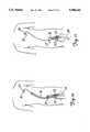
- FIG. 1is a diagrammatic view of an angioplasty catheter system in the vascular system of a patient.
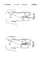
- FIG. 2is an enlarged view in side elevation of one embodiment of the present invention which shows guide wire captivation.
- FIG. 3is a sectional view of the captivation tool in FIG. 2.
- FIG. 4is a detail sectional view of an operative segment of a guide wire which is one preferred embodiment of the present invention.
- FIG. 5is a view in end elevation showing one preferred embodiment of the present invention.
- FIG. 6is a view in side elevation along line 6--6 in FIG. 5.
- FIG.7is an enlarged fragmentary detail of portion A in FIG. 5 illustrating the placement of a catheter assembly, shown in section, into the tool housing.
- FIGS. 8-13depict a preferred method of use for the present invention.
- FIG. 8shows the catheter and guide wire pre-inserted in a vessel of a patient, with the operative segment on the guide wire disposed within the proximal end of the dilatation catheter.
- FIG. 9shows the tool being placed over the operative segment of the guide wire.
- FIG. 10shows the dilatation catheter being withdrawn over the guide wire and past the tool.
- FIG. 11shows the dilatation catheter external from the patient's body with the tool adjacent the operative segment on the guide wire.
- FIG. 12shows the dilatation catheter external to the patient's body with the tool removed from adjacent the guide wire.
- FIG. 13shows the guide wire remaining in place in the vessel of the patient with the tool and dilatation catheter removed.
- FIG. 14is a detail sectional view of an operative segment of a guide wire which is another preferred embodiment of the present invention.
- FIG. 15is a detail sectional view of an operative segment of a guide wire which is another preferred embodiment of the present invention.
- FIG. 16is a schematic illustration of a guide wire extension containing an operative segment.
- FIG. 17is a schematic illustration of a tool which includes an electromagnet.
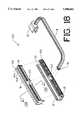
- FIG. 18is an exploded view of the three major components of the tool of an alternative embodiment.
- FIG. 19is an isometric view of the operation of the alternative embodiment of FIG. 18.
- FIG. 20is a close up view of the catheter receiving notch of the alternative embodiment.
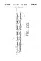
- FIG. 21is a longitudinally sectioned view of the proximal end of the guide wire of the preferred embodiment.
- FIG. 22is a perspective view of the guide catheter exchange device of the present invention.
- FIG. 22Ais a partial sectional view of one embodiment of the guide catheter exchange device of FIG. 22.
- FIG. 22Bis a partial sectional view showing an alternative embodiment of the guide catheter exchange device of FIG. 22.
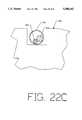
- FIG. 22Cis a cross-sectional view of the guide catheter exchange device shown in FIG. 22 operative segment positioned in a captivation tool.
- FIG. 22Dis a partial cross-sectional view showing one alternative embodiment of the operative segment of the guide catheter exchange device of FIG. 22.
- FIG. 22Eis a partial cross-sectional view showing another alternative embodiment of the operative segment of the guide catheter exchange device of FIG. 22.
- FIG. 22Fis a perspective view of another embodiment of the guide catheter exchange device of the present invention.
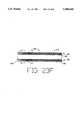
- FIG. 23is a perspective view of an alternative embodiment of the guide catheter exchange device of the present invention.
- FIG. 23Ais a partial perspective view of the guide catheter exchange device shown in FIG. 23.
- FIG. 23Bis a partial cross-sectional view of one embodiment of the operative segment shown in FIG. 23.
- FIG. 23Cis a partial sectional view of one embodiment of the operative segment shown in FIG. 23.
- FIG. 23Dis a cross-sectional view of the operative segment shown in FIG. 23C.
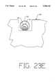
- FIG. 23Eis a cross-sectional view of the guide catheter exchange device of FIG. 23 operative segment located in a captivation tool.
- FIG. 23Fis a partial sectional view of an alternative embodiment of the operative segment shown in FIG. 23.
- FIG. 23Gis a perspective view of an alternative embodiment of the guide catheter exchange device of the present invention.
- FIG. 24is an alternative embodiment of the guide catheter exchange device of the present invention.
- FIG. 24Ais a partial sectional view of the operative segment of the guide catheter exchange device shown in FIG. 24.
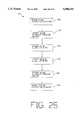
- FIG. 25is a flow diagram of a guide catheter exchange procedure using the guide catheter exchange device of the present invention.
- the present inventionis a method and device for controlling movement of an elongated shaft in the catheterization of a patient, where a portion of the shaft is inserted within the patient. More precisely, the present invention is a method and device for controlling the movement of an elongated shaft extending through an elongated tube, wherein a portion of both the tube and shaft are inserted within the patient.
- the shaftis a guide wire and the tube is a catheter with a lumen for slidably receiving the guide wire.
- a vascular system 20 and an angioplasty catheter system 32are shown in FIG. 1.
- entry into the vascular system 20is typically through the femoral artery in the thigh (as schematically shown at 21 in FIGS. 2 and 8).
- a distal portion of the vascular system 20includes a descending aorta 22, an aortic arch 24, and an ascending aorta 26. Extending from the ascending aorta 26 is a coronary artery 28, in which a stenosis 30 is formed.
- the angioplasty catheter system 32includes a guide catheter 34, a guide wire 36 extending through the guide catheter 34, and a dilatation catheter 38 with an inflatable balloon 40 mounted at a distal end 39 of a main tubular shaft 42 of the dilatation catheter 38.
- the dilatation catheter 38is designed for use in conjunction with a guide wire, and has a guide wire lumen 45 (FIGS. 2, 3 and 7) extending along its entire length.
- the dilatation catheter 38also has an inflation lumen 47 extending therethrough.
- the dilatation catheter 38may be a dual lumen or coaxial lumen structure. In a coaxial arrangement (as shown), the inflation lumen 47 is provided between the outer main shaft 42 and an inner tubular shaft 41 disposed coaxially within the outer shaft 42.
- the guide wire lumen 45is thus defined by the interior of the inner tubular shaft 41.
- a proximal portion of the guide wire 36protrudes proximally out of a proximal end 43 of the dilatation catheter 38 and a proximal portion of the dilatation catheter 38 protrudes proximally out of a Y-adaptor 37 connected to a proximal end of the guide catheter 34.
- An inflation manifold 44is connected to the proximal end 43 of the dilatation catheter 38 for facilitating inflation of the balloon 40.
- An inflation device 46 for inflating the balloon 40is in fluid communication with the balloon 40 via the inflation manifold 44 and the inflation lumen 47.
- the basic angioplasty procedureconsists of inserting the guide catheter 34 into the vascular system 20 at the femoral artery.
- the guide catheter 34is advanced through the vascular system 20 until a distal end of the guide catheter 34 is adjacent the mouth of the coronary artery 28 as shown in FIG. 1.
- the distal end 39 of the dilatation catheter 38is loaded onto and over a proximal end of the guide wire 36 and advanced over the guide wire 36 until the distal end 39 of the dilatation catheter 38 is adjacent a distal end of the guide wire 36.
- the assembled combination of the guide wire 36 and the dilatation catheter 38is inserted into the proximal end of the guide catheter 34 and advanced distally therethrough, retracing the already established path of the guide catheter 34 through the patient's vascular system 20.
- the guide wire 36 and the dilatation catheter 38 combinationtypically is advanced distally until adjacent the distal end of the guide catheter 34.
- the distal tip of the guide wire 36is then advanced separately and manipulated into the artery tree to and across the stenosed artery.
- the dilatation catheter 38is then advanced over the guide wire 36 to position the balloon 40 across the stenosis 30.
- the balloon 40is inflated to dilate the stenosis 30 to re-establish acceptable blood flow through the artery.
- the dilatation catheter 38must be exchanged for another dilatation catheter to complete the angioplasty procedure.
- the present inventionfacilitates holding the guide wire 36 in place across the stenosis 30 without requiring an exchange wire, an extension wire or additional intravascular devices to accomplish the dilatation catheter exchange over the guide wire 36.
- meansare provided proximally of the guide catheter Y-adaptor 37 to cooperate with the guide wire 36 for maintaining the position of the guide wire 36 across the stenosis 30.
- One preferred embodiment of the present inventionemploys a captivation tool 50 which cooperates with an operative segment 52 of the guide wire 36 to create a coupling force field between the tool 50 and the operative segment 52.
- the coupling force fieldis defined by an energy field (such as a magnetic field).
- the force generated by the fieldis strong enough to maintain the position of the guide wire 36 relative to the tool 50 when the dilatation catheter 38 is aligned over the operative segment 52 of the guide wire 36, and particularly when the dilatation catheter 38 is moved over the guide wire 36.
- the operative segment 52 of the guide wire 36is located on a proximal portion of the guide wire 36 and is positioned so that the operative segment 52 is located some distance beyond the proximal end of the guide catheter Y-adaptor 37.
- the operative segment 52 of the guide wire 36includes a plurality of magnetically permeable segments 54 secured on the guide wire 36 at locations along the guide wire 36.
- suitable magnetically permeable materialsare Rodar, manufactured by T. N. Wilbur B. Driver Company and available in tube form from Uniform Tubes of Collegeville, Pa.; Hiperco Alloy 50, manufactured by Carpenter Steel of Reading, Pa.; Permendur or 2V Permendur, listed as high permeable magnetic materials having large saturation flux densities in the CRC Handbook of Chemistry and Physics, 47th ed.; or any other material with a suitably large residual induction).
- the operative segment 52includes a plurality of magnetically permeable segments 54 secured about a reduced diameter portion 57 of guide wire 36.
- Non-magnetically permeable segments 53are disposed between and about each of the magnetically permeable segments 54, respectively.
- the outside diameter of the operative segment 52stays essentially the same as the outside diameter of the guide wire 36, and the transitions between magnetically permeable and non-magnetically permeable materials are smooth.
- the captivation tool 50includes a housing member 56.
- the housing member 56includes a longitudinal slot 60 defined by a pair of side slot surfaces 62 and 64, and a bottom slot surface 66.
- the slot 60provides a space with sufficient size to slidably receive the dilatation catheter 38 and allow the dilatation catheter 38 to longitudinally pass freely through the slot 60, yet still restrict lateral movement of the dilatation catheter 38 between the slot surfaces 62, 64, and 66.
- the housing member 56also includes a plurality of rectangular-shaped magnetic sections 72 (shown in phantom in FIG. 5) which have exposed surfaces at bottom slot surface 66. As best seen in FIG. 6, the magnetic sections 72 are provided at longitudinally spaced locations along the housing member 56 corresponding to the spacing of the magnetically permeable sections 54 on the guide wire 36. The magnetically permeable sections 54 on the guide wire 36 and the magnetic sections 72 in the housing member 56 are spaced such that they can be aligned across from each other as shown in FIG. 3. Although the material of the bottom slot surface 66 alternates between the housing member 56 and the magnetic sections 72, the bottom slot surface 66 is smooth.
- the magnetic sections 72are preferably made from a strong magnetic material with a large cohesive force (such as neodynium boron iron) that can hold a magnetization through a relatively thin section.
- the size and spacing of the magnetic sections 72, as well as the size and spacing of the magnetically permeable sections 54 of the operative segment 52 on the guide wire 36,are chosen to maximize the longitudinal attractive force on the guide wire 36 while minimizing the radial attractive force on the guide wire 36.
- the net force for maintaining the position of the guide wire 36 relative to the tool 50is governed by the equation:
- F netis the net force available to maintain the position of the guide wire 36
- F Lis the longitudinal force of attraction between the tool 50 and the operative segment 52 on the guide wire 36
- F Ris the radial force of attraction between the tool 50 and the operative segment 52
- ⁇is the friction coefficient between the guide wire 36 and the dilatation catheter 38.
- the friction coefficient ⁇may be reduced through the use of lubricous coatings and materials, and the attractive forces F L and F R may be optimized through the use of mathematical modeling techniques known in the art. For example, positioning the magnetic sections 72 in the tool 50 such that the polarity of the magnetic sections 72 alternates between magnetic-sections 72 reduces the radial attractive force F R . Such alternation increases the total effective magnetic field, thereby increasing the longitudinal holding force.
- the total coupling force between the operative segment 52 and the tool 50is proportional to the number of magnetic sections 72 in the tool 50.
- the guide wire 36has an outside diameter of 0.018 inches.
- the operative segment 52has a length of approximately 10 inches with approximately 50 magnetically permeable sections 54, each having a length of 0.1 inch, separated by non-magnetically permeable sections 53 with a length of 0.1 inch.
- a non-operative segment approximately 2 inches longis attached to the proximal end of the operative segment 52.
- the tool 50is approximately 4.0 inches long, 1.0 inch high, and 1.0 inch wide, with 20 magnetic sections (magnets) 72 spaced 0.2 inches apart.
- the magnetic sections 72are 0.04 inches thick and 0.75 inches high, with a width of 0.75 inches.
- the height and width of the magnetic sections 72are determined as a function of the thickness of the magnetic sections 72.
- the magnetic poles of the magnetic sections 72are alternated so that like poles of the spaced magnetic alternated so that like poles of the spaced magnetic sections 72 are facing each other.
- the slot 60 for receiving the dilatation catheter 38is 0.10 inch wide and 0.10 inch deep.
- the holes 68 centered under each of the magnetic sections 72 (for gluing magnetic sections 72 in place during assembly)are approximately 0.04 inches in diameter.
- the device of the present invention for facilitating a dilatation catheter exchange while maintaining a guide wire in place within a vesselis employed in the following manner.
- performing such an exchangerequires that the angioplasty catheter system 32 already be in place in the vascular system 20 of the patient as previously described.
- the proximal end of the guide wire 36 and the proximal end 43 of the dilatation catheter 38protrude proximally outside the patient as seen in FIG. 8, with the proximal end of the guide wire 36 extending proximally beyond the proximal end 43 of the dilatation catheter 38.
- the operative segment 52 of the guide wire 36(identified schematically by the "xxx's" in FIGS.
- the physiciangrasps the proximal end of the guide wire 36 to maintain its distal end in place across the stenosis 30. The physician then places a proximal portion of the dilatation catheter 38 (having the operative segment 52 extending therein) into the slot 60 of the housing member 56 (see FIGS. 7 and 9) and aligns the operative segment 52 with the tool 50.
- the alignment of the operative segment 52 with the tool 50is relatively simple because the operative segment 52 is longer than the slot 60 in the tool 50, and the distance between the magnetically permeable sections 54 on the guide wire 36 and the corresponding magnetic sections 72 on the tool 50 is relatively small.
- the resultis that when the operative segment 52 is positioned within the slot 60 of the tool 50 only a small amount of movement (less than half the distance between the magnetic sections 72 on the tool 50) is required to align the magnetically active portions of the operative segment 52 and the tool 50.
- the spacing between the magnetic sections 72becomes smaller, less movement is required to align the tool 50 and the operative segment 50.
- the tool 50 and the operative segment 52effectively become self-aligning, and simply positioning the operative segment 52 within the slot 60 of the tool 50 ensures proper alignment.
- the physicianreleases the guide wire 36 proximal to the tool 50 and then grasps the proximal end 43 of the dilatation catheter 38 proximally of the tool 50.
- the dilatation catheter 38is pulled proximally over the guide wire 36 and past the tool 50 while holding the tool 50 (and thus the guide wire 36) in a stationary position relative to the patient (see FIG. 10).
- the physicianmay choose to hold the tool 50 in his hand, or alternately the physician may place the tool 50 on the table to hold the tool 50 stationary.
- the longitudinal magnetic attraction between the guide wire 36 and the captivation tool 50is greater than the friction between the guide wire 36 and the inner catheter shaft 41.
- the dilatation catheter 38may be pulled over the guide wire 36 while maintaining the guide wire 36 in the same position relative to the captivation tool 50. This ultimately maintains the guide wire 36 in position across the stenosis 30 during this maneuver, as long as the tool 50 is held generally stationary with respect to the patient.
- the catheter 38is withdrawn until the distal end of the dilatation catheter 38 is exposed outside of the patient's body as seen in FIG. 11. As such, a portion of the guide wire 36 will be exposed between the distal end of the catheter 38 and the proximal end of the guide catheter 34, which protrudes outside the patient's body.
- the physiciangrasps this exposed portion of the guide wire 36 distal to the tool 50 and the distal end of the dilatation catheter 38 as at 76.
- the physicianlaterally separates the catheter 38 and the guide wire 36 therein from the tool 50 by overcoming the radial magnetic forces between the guide wire operative segment 52 and the tool 50.
- the physicianthen completely withdraws the first balloon catheter 38 proximally off of the guide wire 36.
- the guide wire 36has thus been held in a generally stationary position during the entire catheter removal procedure in a very simple and elegant manner, which can be managed by the physician without the need for extra persons to hold or manipulate additional catheter or guide wire components.
- a second dilatation catheteris placed on the proximal end of the guide wire 36 and moved distally over the guide wire 36 until the operative segment 52 of the guide wire 36 is positioned within a distal end of the second dilatation catheter (preferably within the second catheter at a point proximal to the balloon thereon).
- the operative segment 52 of the guide wire 36 and the tool 50are positioned together (as previously described) until the operative segment 52 is magnetically aligned with the magnetic sections 72 of the captivation tool 50.
- the captivation tool 50is held stationary relative to the patient to ultimately maintain the distal end of the guide wire 36 in place across the stenosis 30.
- the second dilatation catheteris advanced distally over the guide wire 36 until the proximal end of the guide wire 36 extends beyond a proximal end of the second dilatation catheter.
- the physicianthen grasps the guide wire 36 proximal to the tool 50 and dilatation catheter manifold 44, and separates the second dilatation catheter and the guide wire 36 therein from the tool 50.
- the second dilatation catheteris then further advanced distally over the guide wire 36 until the balloon of the second dilatation catheter is across the stenosis 30 for dilatation.
- the dilatation catheter exchange procedure using the captivation tool 50 and operative segment 52can thus be repeated in this manner as necessary.
- the present inventionis ideally suited for facilitating catheter exchanges without the need for a long exchange guide wire, a modified catheter, or additional intravascular devices such as a guide wire holding balloon for "trapping" the guide wire against a wall of the guide catheter.
- the present inventionallows catheter exchanges over a standard length guide wire using a catheter having a full length guide wire lumen. Additionally, the procedure may be performed by a single physician and without the prolonged use of X-ray fluoroscopy used to observe the position of the guide wire, since the guide wire is held stationary by use of the present invention and thus its position need not be continuously observed.
- the utility of the present inventionis not limited to catheter exchange procedures.
- the present inventionmay be used as a "third hand" during a catheterization procedure.
- the physicianis required to simultaneously manipulate the guide wire 36, the dilatation catheter 38, and the guide catheter 34.
- the simultaneous manipulationoften requires the use of additional medical personnel, which increases the cost and complexity of the procedure.
- the present inventioneliminates the need for the physician (or a second person) to continually hold the guide wire 36 during the procedure.
- the operative segment 52 provided on the guide wire 36can be made long enough to allow the use of more than one tool 50 during a catheterization procedure.
- a second tool 50may be used in place of the physician actually grasping the guide wire 36.
- the operative segment 52 on the guide wire 36may take a number of forms including those shown in FIGS. 14, 15 and 21.
- each of a plurality of non-magnetically permeable segments 58are secured about reduced diameter portions 55 of the guide wire 36A.
- the guide wire 36Ais made of a magnetically permeable material, and segments 58 are a non-magnetically permeable material such as plastics or non-magnetic metals.
- the operative segment 52may include an elongate non-magnetically permeable tubular member 51 with a plurality of solid cylindrically-shaped magnetically permeable segments 54A secured within member 51.
- the tubular member 51is connected to a reduced diameter portion 59 of the guide wire 36.
- operative segment 52is a guide wire segment made of a single material which can exist in either a magnetic or non-magnetic state (such as martensite of austenite steel) depending upon the heat treatment of the material. Alternating sections of the wire are heat treated locally to form alternating magnetic and non-magnetic sections on the guide wire.
- the magnetically permeable materialmay be replaced with permanent magnets.
- the operative segment 52may be provided on a short guide wire extension 74 (e.g., about 12 inches long) for a standard guide wire. As shown schematically in FIG. 16, this short extension 74 would connect to the proximal end of the standard guide wire 76 in a conventional manner, such as shown, e.g., in U.S. Pat. Nos. Gambale et al. 4,922,923; Messner et al. 4,875,489; Crittenden et al. 5,035,686; or Palmer et al. 5,117,838.
- the short extension 74is selectively attachable to the standard guide wire 76 and can be connected and disconnected multiple times during a single procedure.
- short guide wire extension 74with an operative segment 52 allows the physician to perform a catheter exchange using the present invention even if the catheterization procedure was started using a standard guide wire 76.
- the use of the short extension 74 in a catheter exchangemerely requires the additional acts of attaching the extension 74 to the guide wire 76 and withdrawing the original catheter proximally far enough to cover the operative segment 52 on the short extension 74 before positioning the dilatation catheter 38 relative to the tool 50 for magnetic coupling of the extended guide wire and the tool 50.
- the use of such a short guide wire extension 74either for holding the wire/catheter assembly during the procedure or to facilitate a catheter exchange over a stationary wire, is essentially the same as described herein.
- the tool 50may be adapted to fit over the guide catheter 34 (as in a 2-piece "clam shell” design), may be made in the form of a guide catheter extension, or may be incorporated directly into the guide catheter Y-adaptor 37, for example. Additionally, the tool 50 may be designed such that the magnetic sections 72 in the tool 50 are moved within the housing member 57 and away from the slot 60 in the housing member 56. With this feature, the attraction between the tool 50 and the operative segment 52 on the guide wire 36 is effectively "turned off” when the magnetic sections 72 are moved sufficiently laterally away from the slot 60 in the housing member 56 and the operative segment 52 of the guide wire 36 therein to break the magnetic attraction therebetween.
- Magnet fixture block 108receives permanent magnets (not shown) in magnet receiving slots 104 as described above.
- the magnetsare placed with alternating polarity to increase the effective axial holding force and decrease the effective normal force which reduces longitudinal friction.
- Magnet fixture block 108is preferably molded of a polycarbonate, with General Electric Lexan HP2X-42046 being the recommended material.
- Bottom block 102is molded of a similar but clear material, such as General Electric Lexan HP2X-111, and engages with magnet fixture block 108, through receiving channel 101.
- magnet fixture block 108is held within receiving channel 101 by the engagement of longitudinal protrusions 116 and 114 of magnetic fixture block 108 within longitudinal channels 115 and 117 of bottom block 102, respectively.
- Configured catheter receiving notch 118stabilizes the position of the catheter assembly as discussed in greater detail below.
- Operator handle 111is molded of Lexan HP2X-111 (clear) material. It has a catheter receiving element 112 and a configured engagement latch 110, which is fixedly engaged within receiving notch 103 of bottom block 102 and receiving notch 105 of magnet fixture block 108.
- FIG. 19is a isometric composite view of the alternative embodiment of FIG. 18 in operation.
- Catheter receiving element 112slidably engages y-adapter 113 of catheter assembly 119 as shown.
- Catheter assembly 119is stabilized within configured catheter receiving notch 118. The operator conveniently grasps the entire assembly using handle 111.
- FIG. 20A cross sectional view of the assembled tool is shown in FIG. 20.
- Inclines 120 and 122direct catheter assembly 119 into catheter stabilization channel 118, which is configured to hold catheter assembly 119 within the above described magnetic field.
- Permanent magnet 127is shown held in place by contact with molded spikes 129a, 129b, and 129c.
- the inner core 132 of the assemblyis preferably a wire of Hyperco 50B, which is an alloy of 48.5% cobalt, 48.5% iron, and 3% vanadium. It is commercially available as explained above and has a diameter of about 0.011 inch.
- Inner core 132is circumferentially ground to produce a reduced diameter of about 0.0045 inch for a distance of about 0.075 inch at areas 136 and 140, which are separated by distance 138, also about 0.075 inch.
- Proximal distance 134is about 10.075 inches, and distance 142 is about 0.5 inch.
- the proximal end of a standard spring coil guide(not shown for clarity) is butt welded to distal end 144 of inner core 132.
- Inner core 132is coated with an adhesive, which is preferably Hysol 9412 to fill the ground areas 136 and 140 to an overall depth at the unground areas of about 0.001 inch.
- the resulting structurehas a uniform outside diameter of about 0.011 inch, which is covered before curing is completed by hypotubing 128 of 304 stainless steel.
- the wall thickness of hypotubing 128is chosen to provide a standard finished outside diameter, such as 0.018 or 0.014 inch.
- Hypotubing 128extends distally of distal end 144 of inner core 132 by at least 0.5 inch along area 146 to provide strain relief to the butt weld at distal end 144.
- Proximal end 130is ground to a smooth hemispherical shape.
- a guide wire (or guide wire extension) 86includes an operative segment 52 (as previously described) and the guide wire 86 is, in use, inserted within a lumen of a catheter 88.
- a tool 90 in this embodimentincludes an electromagnet 92 which has selectively activated sections therein aligned to cooperate within the operative segment 52, and which is connected to a current source 94 through an on/off switch 96. Operation of the switch 96 thus controls the application of current to the electromagnet 92 and the creation of a magnetic field thereby.
- the selectively activated sections within the tool 90may be energized by wall current (AC) or rectified wall current (DC), either of which can be turned off by switch 96 to break the holding force between the tool 90 and the guide wire 86.
- the coupling force field between the guide wire and the captivation toolmay be generated by the use of electrostatic or electric fields.
- the coupling force between the tool and the guide wirecan operate through the catheter body, and there is no contact required between the tool and the guide wire.
- the present inventionincludes a guide catheter exchange device and method of exchanging guide catheters.
- the guide catheter exchange deviceallows physicians to exchange guide catheters solo during catheterization procedures.
- the guide catheter exchange deviceis useful for many catheterization procedures, including diagnostic, angiography and percutaneous transluminal angioplasty procedures.
- a dilatation balloon systemis placed within a patient's vascular system by first inserting a guide catheter through the patient's femoral, brachial, radial or any other arterial access point and advancing it through the patient's vascular system to a point near the stenotic lesion to be treated.
- a guide wireis advanced through the guide catheter lumen, with the distal end of the guide wire positioned across the stenosis.
- a dilatation catheter, having a balloon located at its distal endis advanced over the guide wire until the balloon is positioned over the stenosis for treatment of the stenosis.
- Circumstances which may require such a proceduremay include the physician's need to accommodate a larger dilatation balloon catheter, the need to locate a stent in the region of the stenosis, or the need to use atherectomy (or treatment requiring larger devices), or the weakening of the present guide catheter due to an angioplasty procedure.
- FIG. 22shows a guide catheter exchange device in accordance with the present invention generally at 200.
- the guide catheter exchange device 200generally includes a body 202 and a support member 204 which extends from the body 202.
- the body 202may include at least one lumen 208 extending therethrough sized to accommodate a guide wire 210, and an additional lumen 212 extending at least partially through the body 202 and sized to accommodate the support member 204.
- the body 202is generally formed of a soft, flexible material.
- the body 202is formed of an extruded polymeric material, such as a polyether blocked amide or PEBA, commonly available under the trade name PEBAX.
- the body 202is approximately 10 centimeters in length and has a distal section 214 which is necked down from a first larger diameter to a second smaller diameter at the distal end 216. Additionally, the distal end 216 may have a radius tip for atraumatic movement of the exchange device 200 and subsequent seating of the distal end 216 in the ostium of the vessel receiving treatment.
- the guide wire lumen 208has an approximate diameter of 0.020 inches sized to accommodate guide wires having outside diameters of 0.018 inches and smaller.
- Support member 204is inserted into the support lumen 212 and secured to the body 202 through an adhesive bond.
- body 202may take on alternative shapes and forms while remaining within the scope of the present invention.
- the body 202could be a clip or a loop to provide controlled movement of support member 204 relative to guide wire 210 while still providing support to guide wire 210 located across the stenosis.
- the body 202may have a varying outside diameter as shown in FIG. 22A, or alternatively, as shown in FIG. 22B, may be formed of a uniform outside diameter.
- the length of body 202may vary in accordance with the desired procedure, the length of body 202 is preferably between 10 and 30 centimeters.
- the body 202is formed by extruding a soft polymeric material over a wire mandrel to form guide wire lumen 208. Additionally, the polymeric material may be extruded over a partial mandrel to form the support member lumen 212 or the support member mandrel may be inserted into the extruded polymeric material before cooling. After cooling, the mandrels are removed and a lubricous coating is applied to the inner surface of guide wire lumen 208 and the outer surface of body 202. It is recognized that the outside diameter of body 202 may be varied by methods such as varying the amount of material deposited on the guide wire lumen mandrel or reheating and reforming the body 202 after cooling.
- Support member 204is inserted into support member lumen 212, and secured using an adhesive bond.
- the support member 204is a wire-like member similar in length to guide wire 210.
- the support member 204is formed of material similar to guide wire 210, but of a heavier construction relative to guide wire 210.
- support member 204is formed of 304SS, has a diameter of 0.038 inches or greater, and a length extending from body 202 of approximately 90 to 120 centimeters.
- Support member 204has an operative segment 220 which can be similar to the guide wire operative segment 52 previously disclosed in the specification and the guide wire operative segment disclosed in U.S. Pat. Ser. No. 08/369,190, filed on Jan. 5, 1995, entitled "Shaft Movement Control Apparatus and Method".
- the operative segment 220along with a guide wire operative segment 222, cooperate with a captivation tool 224 to create a coupling force field between the operative segment 220, operative segment 222, and captivation tool 224 indicated in FIG. 22C.
- the captivation tool 224can be similar to the captivation tool 50 having a magnetically active area as previously disclosed in the specification, including the alternative embodiments shown in FIGS. 18-20.
- operative segment 220 of support member 204is shown in cross-sectional view.
- the operative segment 220includes a core 254, segments 256, and a tubular member 258. Segments 256 are located within notched areas 260 of core 254. Tubular member 258 surrounds core 254, and has an outside diameter approximately equal to the outside diameter of the overall support member 204.
- Core 254is formed of a ferromagnetic material relative to the rest of operative segment 220, and becomes highly magnetic when subjected to a magnetic field.
- the core 254is formed of a HYPERCO 50B, which is an alloy of approximately 48.5 percent cobalt, 48.5 percent iron, 3 percent Vanadium, and trace elements. It is also recognized that core 254 may be formed of other magnetically responsive or magnetically active materials, such as magnetic or paramagnetic materials.
- core 254is formed by first pulling the HYPERCO material through a heated dye to form a HYPERCO wire or core.
- the HYPERCO wireis ground to a desired uniform outside dimension.
- Core 254is notched in equally spaced areas longitudinally along the core 254.
- core 254is notched by a centerless grinding process in which the HYPERCO wire is held longitudinally stationary while a wheel rotates while in contact with the wire for precision grinding each notch.
- operative segment 220includes approximately 180 notched segments 260 which are approximately 0.040 inches in length and 0.004 inches in depth.
- the longitudinal spacing of notched segment 160are similar to the longitudinal spacing of the magnetically active segments in captivation tool 224.
- notched core 254includes a larger major diameter A, and a smaller minor diameter B which together define the notched segments 260.
- a metallic or non-metallic substanceis deposited within notched segments 260 to form segments 256.
- the substanceoccludes the space between the notched segments 260, such that core 254, including segments 256, is now formed of a uniform outer diameter equal to major diameter A.
- Segments 256are formed of a metallic or nonmetallic substance which is non-magnetic or substantially less magnetic than the highly ferromagnetic core 254.
- the operative segment 220, including a core 254 having a plurality of metallic segments 256results in a magnetic "edge" effect at each notched corner. This results in an operative segment having a very strong magnetic orientation in a direction longitudinal to the core 254, and a relatively weak magnetic attraction in a radial direction relative to the core 254.
- a tubular member 258is placed over core 254.
- the tubular member 258is formed of a stainless steel hypotube having an outside diameter approximately equal to the outside diameter of the remaining portion of support member 204, and an inside diameter which is 0.0005 inches greater than the core 254 major diameter A.
- the tubular member 258may be placed over core 254 while located in an adhesive bath for securing the tubular member 258 to the core 254.
- the adhesive bathis HYSOL adhesive, available from Dexter Company, which forms the adhesive layer 262 shown between tubular member 258 and core 254. Adhesive which forms around the outside diameter of tubular member 258 is subsequently removed.
- Operative segment 220is completed by center grinding the distal end 264 of operative segment 220 to compliment a ground portion of the proximal end of support member 204. Operative segment 220 is then securely attached to support member 204 by known means, such as a resistance weld, indicated at 266. Additionally, the proximal end 268 of operative segment 220 is ground smooth.
- operative segment 220 of support member 204is shown in cross-sectional view.
- the operative segment 220can be similar to the operative segment 220 shown in FIG. 22D.
- the operative segment 220includes a core 254, ferromagnetic disks 257, and non-ferromagnetic disks 259. Core 254 is ground to a uniform outside diameter. Ferromagnetic disks 257 and non-ferromagnetic disks 259 are alternately placed over core 254.
- the ferromagnetic disks 257are formed of HYPERCO.
- tubular member 258is placed over ferromagnetic segments 257 and non-ferromagnetic segments 259. Tubular member 258 has an outside diameter approximately equal to the outside diameter of the overall support member 204.
- the guide catheter exchange device 200may include a support member 204 which does not include a body 202.
- the support member 204is positioned adjacent the guide wire 210.
- the guide wire 210does not pass through the support member 204.
- Support member 204provides the necessary support and stability for removing a guide catheter during the guide catheter exchange procedure, while providing protection to the guide wire 210, which is held in a stationary position across the stenosis.
- the operative segment 220 of the support membercan include ferromagnetic segments via core construction.
- the corecan be formed of other magnetically responsive or magnetically active materials, such as magnetic or paramagnetic materials.
- the guide catheter exchange device 200includes a generally tubular shaped member 270 having a distal end 272, a proximal end 274 and a lumen 276 extending therethrough.
- the lumen 276is sufficiently sized to allow guide wire 210 to pass through the lumen 276.
- guide catheter exchange device 200may be positioned over guide wire 210, or alternatively as shown in FIG. 23G, guide catheter exchange device 200 may be positioned adjacent guide wire 210.
- Generally tubular shaped member 270includes a tubular body 278 with an operative segment 220 located at its proximal end 274.
- the distal end 272 of the guide catheter exchange device 200allows for stabilization and protection of the guide wire 210, and structural support for the guide catheter during a guide catheter exchange procedure.
- the operative segment 220 located at the tubular member 270 proximal end 274is formed integral the tubular shaped member 270.
- the operative segment 220allows a physician to use the guide catheter exchange device 200 for performing a guide catheter exchange procedure by a solo physician without the need of exchange wires, while maintaining the position of the previously inserted guide wire across the stenotic lesion.
- Tubular body 278is formed from an extruded polymeric material through an extrusion process which may include extruding a polymeric material over a wire mandrel, or a free extrusion process.
- the operative segment 220is magnetically responsive for coupling to a captivation tool 224 indicated at FIG. 23E.
- the generally tubular shaped member 270may be formed of a uniform outside diameter, indicated in FIG. 23.
- tubular shaped member 270may have a varying outside diameter as indicated in FIG. 23A where operative segment 220 is formed of a larger outside diameter relative to tubular body 278.
- the tubular shaped member 270 operative segment 220includes a base layer 282, a magnetically responsive layer 284, and an outside layer 286.
- the base layer 282is formed of an extruded polymeric material in a generally tubular shape.
- Magnetically responsive layer 284is formed by wrapping or braiding wire or ribbon 288 around base layer 282.
- magnetically responsive layer 284is formed of a highly ferromagnetic material, such as HYPERCO ribbon.
- the magnetically responsive layer 284includes a first layer 290 and a second layer 292.
- the first layer 290is formed by coiling 0.002 inch by 0.004 inch HYPERCO ribbon about the base layer 282.
- the second layer 292is formed by intermittently coiling a similar 0.002 inch by 0.004 inch HYPERCO ribbon around the previously coiled first layer 290, with a spacing between the intermittent coils of approximately 0.02 inches, indicated at A, matching the segmented active area of captivation tool 224.
- the coiled layer 284 configuration including the size and spacing of the first layer 290 and second layer 292,are chosen to maximize the longitudinal attractive force between the captivation tool 224 and operative segment 220, while minimizing the radial attractive force between captivation tool 224 and operative segment 220.
- a smooth outer surfaceis provided to operative segment 220 by outside layer 286, where a soft polymeric material is extruded over the coiled layer 284. Additionally, a soft, rounded end 294 may be secured to the operative segment 220 by known methods, such as heat welding.
- the operative segment 220includes a generally tubular member 298 formed of a polymeric material, such as PEBA, with cores 300 located within cavities 302 integral the tubular member 298.
- the cores 300are preferably formed of a highly paramagnetic, ferromagnetic, or magnetic material. In one embodiment, the cores 300 are formed of notched HYPERCO.
- the operative segment 220may be formed by extruding tubular member 298 over a wire mandrel, and inserting core pins 300 within the tubular member 298 before cooling.
- operative segment 220may be formed by first extruding a polymeric material over a wire mandrel to form tubular member 298, including smaller mandrels to form cavities 302. Core pins 300 are then inserted into cavities 302 and attached by adhesive. Additionally, a smooth end 304 may be attached to operative segment 220.
- the operative segment 220includes a generally tubular base layer 282 formed of an extruded polymeric material in a generally tubular shape.
- Magnetically responsive layer 284is formed by alternately positioning ferromagnetic disks 283 and non-ferromagnetic disks 285 over the base layer 282.
- the width of disks 283 and 285may be formed to match the magnetically active segments of the captivation tool 224.
- an outside layer 286may be extruded over the disks 283 and 285, and a soft rounded end 294 may be secured to operative segment 220.
- tubular shaped member 270may include a single lumen extending therethrough, or alteratively, may be formed including a multi-lumen catheter member.
- the operative segment 220 active areasmay be formed around, or encircle, the single or multi-lumens, as shown in FIGS. 23, 23A, 23B, 23C, and 23D, or the active area may be located adjacent the lumen extending therethrough as shown in FIG. 24.
- the guide catheter exchange device of FIG. 23can be utilized without placing the guide wire 210 through the lumen 276 thereof.
- the exchangeis accomplished by placing the guide catheter exchange device 200 along side of the guide wire 210 within the lumen of the guide catheter to be exchanged.
- the operative segment 220 of the guide catheter exchange device 200can include ferromagnetic segments, or in the alternative, can be formed of other magnetically responsive or magnetically active materials such as magnetic or paramagnetic materials.
- FIG. 24yet another alternative embodiment of the generally tubular shaped member 270 having an operative segment 220 is shown generally at 310.
- the operative segment 220is shown in cross-sectional view in FIG. 24A.
- Operative segment 220includes a guide wire lumen 208 and a magnetically active core 314 located within a soft, flexible layer 312.
- the operative segment 220is formed by simultaneous extrusion of a soft polymeric material over a wire mandrel (to form guide wire lumen 208) and magnetically active core 314.
- a first layer of polymeric materialmay be extruded over a mandrel forming guide wire lumen 208; and after cooling, the magnetically active core 314 may be placed next to the extruded mandrel, and a second extrusion layer is extruded over both the core 314 and extruded mandrel.
- Core 314is formed of a magnetically active or magnetically responsive material which preferably may be highly paramagnetic, ferromagnetic or magnetic.
- core 314is formed of a notched HYPERCO wire. It is recognized that operative segment 220 may take on many different shapes and sizes.
- the size of core 314may be similar to the size of guide wire lumen 208, or alternatively, core 314 may be larger relative to guide wire lumen 208.
- the guide catheter exchange device 200 of the present inventionallows a guide catheter exchange procedure to be performed by a solo physician without requiring an exchange wire, an extension wire, or additional intravascular devices to accomplish a guide catheter exchange procedure over the guide wire 210 while maintaining the position of the guide wire across the stenosis. It is desirable to hold the guide wire 210 and place it across the stenosis during a guide catheter exchange procedure to eliminate the need to reestablish the position of the guide wire 210 by retracing the tortuous path to the stenosis after the guide catheter is exchanged. Maintaining the guide wire 210 in place after an initial dilatation also provides the physician with a path through the stenosis in case of an abrupt closure of the vessel.
- captivation tool 224cooperates with operative segment 220 of the guide catheter exchange device 200, and an operative segment 222 of the guide wire 210, to create a coupling force field between the captivation tool 224, the operative segment 220 and operative segment 222.
- the coupling force fieldis defined by an energy field (such as a magnetic field). The force generated by the field is strong enough to maintain the position of the guide catheter exchange device 200 and guide wire 210 relative to the captivation tool 224 when the guide catheter is aligned over the operative segments 220 and 222, and particularly when the guide catheter is moved over the guide wire 210 and guide catheter exchange device 200.
- a physicianmay desire to perform a guide catheter exchange procedure after a dilatation catheter system has been located within a patient's vascular system.
- a guide catheter exchange method flow diagramis shown generally at 318.
- the dilatation catheteris first removed using the procedure previously described within this specification indicated at 320.
- the physiciangrasps the proximal end of the guide wire 210 to maintain its distal end in place across the stenosis.
- the physicianthen places the guide wire operative segment 222 into the slot of the captivation tool 224.
- the guide wire operative segment 222is attracted to the magnetic sections of captivation tool 224 by the resultant magnetic field created therebetween. This results in the guide wire 210 being pulled against the bottom surface of the captivation tool 224.
- the physicianmay now proceed with removal of the dilatation catheter by pulling the dilatation catheter proximally over the guide wire 210 and past captivation tool 224, while holding the captivation tool 224 in a stationary position relative to the patient outside of the guide catheter.
- the dilatation catheteris pulled over the guide wire 210 while maintaining the guide wire 210 in the same position relative to the captivation tool 224, and correspondingly maintaining the guide wire 210 in position across the stenosis.
- the physicianthen separates the guide wire 210 from the captivation tool 224.
- the guide catheter exchange devicemay now be inserted, indicated at 322. While holding the guide wire 210 stationary relative to the patient, the guide catheter exchange device 200 is placed on the proximal end of the guide wire 210 and moved distally over the guide wire 210 until the guide wire operative segment 222 of the guide wire 210 is positioned just distal to the distal end of the guide catheter exchange device 200. The guide wire operative segment 222 is then positioned within captivation tool 224, through guide catheter 230, and brought into magnetic alignment.
- the guide catheter exchange device 200may be positioned within a patient's vascular system adjacent the guide wire 210.
- the captivation tool 224is held stationary relative to the patient to ultimately maintain the distal end of the guide wire 210 in place across the stenosis.
- the guide catheter exchange device 200is advanced distally over the guide wire 210 until the operative segment 220 of the guide catheter exchange device 200 is located just proximal to the captivation tool 224.
- the magnetis released and the guide catheter exchange device 200 is advanced until operative segment 220 and guide wire 210 align by holding the guide wire proximal.
- the first guide catheter 230may now be removed. If the captivation tool 224 is attached to guide catheter 230, it is released before guide catheter 230 removal. Holding the captivation tool 224 in one hand, the physician then grasps the proximal end of the guide catheter 230 proximally of the captivation tool 224. The guide catheter 230 is pulled proximally over the guide wire 210 and guide catheter exchange device 200 while holding the tool 224 in a stationary position relative to the patient. The physician may choose to hold the tool 224 in his hand, or alternatively, the physician may place the tool 224 on the table or in a docking station to hold the tool 224 stationary.
- the guide catheter 230is pulled over the guide wire 210 and guide catheter exchange device 200 while maintaining guide wire 210 and guide catheter exchange device 200 stationary relative to the captivation tool 224 and the patient's body.
- the guide catheter 230is withdrawn until the distal end of the guide catheter 230 is exposed outside of the patient's body. As such, a portion of the guide catheter exchange device 200 will be exposed between the distal end of the guide catheter 230 and the patient's body.
- the physiciangrasps this exposed portion of the guide catheter exchange device 200, and separates it from the captivation tool 224 overcoming the radial magnetic forces between the guide catheter exchange device 200, guide wire 210, and captivation tool 224.
- the physicianthen completely withdraws the guide catheter 230 proximally off of the guide catheter exchange device 200.
- the second guide catheter 232may now be inserted, indicated at 326. While maintaining the guide catheter exchange device 200 and guide wire 210 stationary relative to the patient, a second guide catheter 232 is placed on the proximal end of the guide catheter exchange device 200 and guide wire 210 and moved distally over the guide catheter exchange device 200 and guide wire 210 until the operative segments 220 and 222 are positioned just distal to the distal end of the second guide catheter 232.
- the guide catheter exchange device operative segment 220 and the guide wire operative segment 222are placed within the captivation tool 224.
- the physicianthen releases the guide catheter exchange device 200 distally of the captivation tool 224, grasps the second guide catheter 232, and distally advances the second guide catheter 232 over the guide catheter exchange device 200 and guide wire 210 longitudinally relative to captivation tool 224 to distally advance the second guide catheter 232 through the patient's vascular system.
- the captivation tool 224is held stationary relative to the patient to ultimately maintain the distal end of the guide wire 210 stationary across the stenosis.
- the second guide catheter 232is advanced distally over the guide catheter exchange device 200 until the proximal end of the guide catheter exchange device 200 and guide wire 210 extend beyond the proximal end of the second guide catheter 232.
- the physicianthen grasps the guide catheter exchange device 200 and guide wire 210 proximal to the captivation tool 224 and second guide catheter, and separates the second guide catheter and the guide catheter exchange device 200 and guide wire 210 within the captivation tool 224.
- the second guide catheteris then further advanced distally over the guide catheter exchange device 200 until it reaches a desired location near the stenosis to be treated.
- the guide catheter exchange device 200is then removed from the patient's body indicated at 328.
- the guide wire operative segment 222is positioned within captivation tool 224 after the guide catheter exchange device operative segment 220 has been moved proximal to captivation tool 224.
- the proximal end of guide catheter exchange device 200is pulled proximally over the guide wire 210, while holding captivation tool 224 stationary to maintain the position of guide wire 210 across the stenosis.
- the guide catheter exchange device 200is pulled distally until the distal end of the guide catheter exchange device 200 is removed from the patient's body.
- the physicianthen grasps the guide wire 210 at a location between the body and the distal end of guide catheter exchange device 200, and removes the remaining portion of the guide catheter exchange device 200 from the guide wire 210.
- a second dilatation cathetermay now be inserted, indicated at 330. While still grasping the guide wire 210, a second dilatation catheter is placed on the proximal end of guide wire 210 and moved distally over the guide wire 210 until the guide wire operative segment 222 of the guide wire 210 is positioned within a distal end of the second dilatation catheter. The guide wire operative segment 222 is magnetically aligned with the magnetic sections of the captivation tool 224 outside of the guide catheter 232.
- the captivation tool 224is held stationary relative to the patient to ultimately maintain the distal end of the guide wire 210 in place across the stenosis.
- the second dilatation catheteris advanced distally over the guide wire 210 until the proximal end of the guide wire 210 extends beyond a proximal end of the second dilatation catheter.
- the physiciangrasps the guide wire 210 proximal to the captivation tool 224 and dilatation catheter manifold, and separates the second dilatation catheter and the guide wire 210 therein from the captivation tool 224.
- the second dilatation catheteris then further advanced distally over the guide wire 210 until the balloon of the second dilatation catheter is positioned across the stenosis for dilatation.
- the guide catheter exchange device 200is used to perform guide catheter exchange procedures, while maintaining the position of the guide wire 210 relative to the stenosis.
- the present inventionis ideally suited for facilitating guide catheter exchanges without the need for a long exchange guide wire, a modified guide catheter, or additional intravascular devices.
- the present inventionallows guide catheter exchanges over a standard length guide wire using a guide catheter having a full length lumen. Additionally, the procedure may be performed by a single physician and without the prolonged use of x-ray fluoroscopy used to observe the position of the guide wire 210, since the guide wire 210 is held stationary by use of the present invention, and thus, its position need not be continuously observed.
- the guide catheter exchange device 200 of the present invention having an operative segment 220may be used with other dilatation catheter exchange procedures which do not employ the use of a guide wire having a magnetically active segment at its proximal end.
- other methodsmay be employed to remove the balloon dilatation catheter during the guide catheter exchange procedure, such as guide wire extensions, rapid exchange catheter systems, over-the-wire and single operator exchange procedures.
- the guide catheter exchange device of the present inventionmay be located adjacent the guide wire or be positioned over the guide wire during a guide catheter exchange procedure, while protecting the guide wire and providing support and stability during the guide catheter exchange procedure.
- operative segment 220may be provided on a short guide catheter exchange device extension. The short extension would connect to the proximal end of a larger guide wire to form a support member similar to the support member shown in FIG. 22F, or similarly may be a tubular shaped guide wire extension which is securely attached to a tubular member to form a guide wire exchange device as shown in FIG. 23.
Landscapes
- Health & Medical Sciences (AREA)
- Life Sciences & Earth Sciences (AREA)
- Biophysics (AREA)
- Pulmonology (AREA)
- Engineering & Computer Science (AREA)
- Anesthesiology (AREA)
- Biomedical Technology (AREA)
- Heart & Thoracic Surgery (AREA)
- Hematology (AREA)
- Animal Behavior & Ethology (AREA)
- General Health & Medical Sciences (AREA)
- Public Health (AREA)
- Veterinary Medicine (AREA)
- Media Introduction/Drainage Providing Device (AREA)
Abstract
Description
F.sub.net =F.sub.L -μF.sub.R
Claims (36)
Priority Applications (2)
| Application Number | Priority Date | Filing Date | Title |
|---|---|---|---|
| US08/397,578US5588442A (en) | 1992-08-12 | 1995-03-02 | Shaft movement control apparatus and method |
| PCT/US1995/017004WO1996026669A1 (en) | 1995-03-02 | 1995-12-27 | Shaft movement control apparatus and method |
Applications Claiming Priority (3)
| Application Number | Priority Date | Filing Date | Title |
|---|---|---|---|
| US07/929,083US5623943A (en) | 1992-08-12 | 1992-08-12 | Magnetic medical shaft movement control device and method |
| US08/048,492US5555893A (en) | 1992-08-12 | 1993-04-16 | Shaft movement control apparatus |
| US08/397,578US5588442A (en) | 1992-08-12 | 1995-03-02 | Shaft movement control apparatus and method |
Related Parent Applications (1)
| Application Number | Title | Priority Date | Filing Date |
|---|---|---|---|
| US08/048,492Continuation-In-PartUS5555893A (en) | 1992-08-12 | 1993-04-16 | Shaft movement control apparatus |
Publications (1)
| Publication Number | Publication Date |
|---|---|
| US5588442Atrue US5588442A (en) | 1996-12-31 |
Family
ID=23571767
Family Applications (1)
| Application Number | Title | Priority Date | Filing Date |
|---|---|---|---|
| US08/397,578Expired - LifetimeUS5588442A (en) | 1992-08-12 | 1995-03-02 | Shaft movement control apparatus and method |
Country Status (2)
| Country | Link |
|---|---|
| US (1) | US5588442A (en) |
| WO (1) | WO1996026669A1 (en) |
Cited By (93)
| Publication number | Priority date | Publication date | Assignee | Title |
|---|---|---|---|---|
| US6010464A (en)* | 1998-01-02 | 2000-01-04 | Scimed Life Systems, Inc. | Controlled guide wire resistance washer for guide catheter exchange device |
| US6517550B1 (en) | 2000-02-02 | 2003-02-11 | Board Of Regents, The University Of Texas System | Foreign body retrieval device |
| US6635022B2 (en) | 1995-03-02 | 2003-10-21 | Scimed Life Systems, Inc. | Braidless guide catheter |
| US20040260237A1 (en)* | 2003-06-17 | 2004-12-23 | Paul Squadrito | Inflation adaptor with magnetically-assisted loading |
| US20050209609A1 (en)* | 2004-02-24 | 2005-09-22 | Board Of Regents, The University Of Texas System | Foreign body retrieval devices |
| US7204464B2 (en) | 2005-01-21 | 2007-04-17 | Boston Scientific Scimed, Inc. | Medical wire holder |
| US20080297287A1 (en)* | 2007-05-30 | 2008-12-04 | Magnetecs, Inc. | Magnetic linear actuator for deployable catheter tools |
| US20090054909A1 (en)* | 2007-07-12 | 2009-02-26 | Board Of Regents Of The University Of Nebraska | Methods and systems of actuation in robotic devices |
| US7769427B2 (en) | 2002-07-16 | 2010-08-03 | Magnetics, Inc. | Apparatus and method for catheter guidance control and imaging |
| US7794407B2 (en) | 2006-10-23 | 2010-09-14 | Bard Access Systems, Inc. | Method of locating the tip of a central venous catheter |
| US7869854B2 (en) | 2006-02-23 | 2011-01-11 | Magnetecs, Inc. | Apparatus for magnetically deployable catheter with MOSFET sensor and method for mapping and ablation |
| US7873402B2 (en) | 2003-10-20 | 2011-01-18 | Magnetecs, Inc. | System and method for radar-assisted catheter guidance and control |
| US8027714B2 (en) | 2005-05-27 | 2011-09-27 | Magnetecs, Inc. | Apparatus and method for shaped magnetic field control for catheter, guidance, control, and imaging |
| US8388541B2 (en) | 2007-11-26 | 2013-03-05 | C. R. Bard, Inc. | Integrated system for intravascular placement of a catheter |
| US8388546B2 (en) | 2006-10-23 | 2013-03-05 | Bard Access Systems, Inc. | Method of locating the tip of a central venous catheter |
| US8437833B2 (en) | 2008-10-07 | 2013-05-07 | Bard Access Systems, Inc. | Percutaneous magnetic gastrostomy |
| US8457714B2 (en) | 2008-11-25 | 2013-06-04 | Magnetecs, Inc. | System and method for a catheter impedance seeking device |
| US8478382B2 (en) | 2008-02-11 | 2013-07-02 | C. R. Bard, Inc. | Systems and methods for positioning a catheter |
| US8480629B2 (en) | 2005-01-28 | 2013-07-09 | Boston Scientific Scimed, Inc. | Universal utility board for use with medical devices and methods of use |
| US8604742B2 (en) | 2003-07-08 | 2013-12-10 | Board Of Regents Of The University Of Nebraska | Robotic devices with arms and related methods |
| USD699359S1 (en) | 2011-08-09 | 2014-02-11 | C. R. Bard, Inc. | Ultrasound probe head |
| US8679096B2 (en) | 2007-06-21 | 2014-03-25 | Board Of Regents Of The University Of Nebraska | Multifunctional operational component for robotic devices |
| US8781555B2 (en) | 2007-11-26 | 2014-07-15 | C. R. Bard, Inc. | System for placement of a catheter including a signal-generating stylet |
| US8784336B2 (en) | 2005-08-24 | 2014-07-22 | C. R. Bard, Inc. | Stylet apparatuses and methods of manufacture |
| US8801693B2 (en) | 2010-10-29 | 2014-08-12 | C. R. Bard, Inc. | Bioimpedance-assisted placement of a medical device |
| US8834488B2 (en) | 2006-06-22 | 2014-09-16 | Board Of Regents Of The University Of Nebraska | Magnetically coupleable robotic surgical devices and related methods |
| US8849382B2 (en) | 2007-11-26 | 2014-09-30 | C. R. Bard, Inc. | Apparatus and display methods relating to intravascular placement of a catheter |
| US8894633B2 (en) | 2009-12-17 | 2014-11-25 | Board Of Regents Of The University Of Nebraska | Modular and cooperative medical devices and related systems and methods |
| US8968267B2 (en) | 2010-08-06 | 2015-03-03 | Board Of Regents Of The University Of Nebraska | Methods and systems for handling or delivering materials for natural orifice surgery |
| US8974440B2 (en) | 2007-08-15 | 2015-03-10 | Board Of Regents Of The University Of Nebraska | Modular and cooperative medical devices and related systems and methods |
| USD724745S1 (en) | 2011-08-09 | 2015-03-17 | C. R. Bard, Inc. | Cap for an ultrasound probe |
| US9010214B2 (en) | 2012-06-22 | 2015-04-21 | Board Of Regents Of The University Of Nebraska | Local control robotic surgical devices and related methods |
| US9060781B2 (en) | 2011-06-10 | 2015-06-23 | Board Of Regents Of The University Of Nebraska | Methods, systems, and devices relating to surgical end effectors |
| US9089353B2 (en) | 2011-07-11 | 2015-07-28 | Board Of Regents Of The University Of Nebraska | Robotic surgical devices, systems, and related methods |
| US9125578B2 (en) | 2009-06-12 | 2015-09-08 | Bard Access Systems, Inc. | Apparatus and method for catheter navigation and tip location |
| US9174020B2 (en) | 2013-05-08 | 2015-11-03 | Embolx, Inc. | Device and methods for transvascular tumor embolization with integrated flow regulation |
| US9211107B2 (en) | 2011-11-07 | 2015-12-15 | C. R. Bard, Inc. | Ruggedized ultrasound hydrogel insert |
| US9339206B2 (en) | 2009-06-12 | 2016-05-17 | Bard Access Systems, Inc. | Adaptor for endovascular electrocardiography |
| US9445734B2 (en) | 2009-06-12 | 2016-09-20 | Bard Access Systems, Inc. | Devices and methods for endovascular electrography |
| US9456766B2 (en) | 2007-11-26 | 2016-10-04 | C. R. Bard, Inc. | Apparatus for use with needle insertion guidance system |
| US9492097B2 (en) | 2007-11-26 | 2016-11-15 | C. R. Bard, Inc. | Needle length determination and calibration for insertion guidance system |
| US9498292B2 (en) | 2012-05-01 | 2016-11-22 | Board Of Regents Of The University Of Nebraska | Single site robotic device and related systems and methods |
| US9521961B2 (en) | 2007-11-26 | 2016-12-20 | C. R. Bard, Inc. | Systems and methods for guiding a medical instrument |
| US9532724B2 (en) | 2009-06-12 | 2017-01-03 | Bard Access Systems, Inc. | Apparatus and method for catheter navigation using endovascular energy mapping |
| US9550046B1 (en) | 2016-02-16 | 2017-01-24 | Embolx, Inc. | Balloon catheter and methods of fabrication and use |
| US9554716B2 (en) | 2007-11-26 | 2017-01-31 | C. R. Bard, Inc. | Insertion guidance system for needles and medical components |
| US9579088B2 (en) | 2007-02-20 | 2017-02-28 | Board Of Regents Of The University Of Nebraska | Methods, systems, and devices for surgical visualization and device manipulation |
| US9636031B2 (en) | 2007-11-26 | 2017-05-02 | C.R. Bard, Inc. | Stylets for use with apparatus for intravascular placement of a catheter |
| US9649048B2 (en) | 2007-11-26 | 2017-05-16 | C. R. Bard, Inc. | Systems and methods for breaching a sterile field for intravascular placement of a catheter |
| US9655539B2 (en) | 2009-11-09 | 2017-05-23 | Magnetecs, Inc. | System and method for targeting catheter electrodes |
| US9743987B2 (en) | 2013-03-14 | 2017-08-29 | Board Of Regents Of The University Of Nebraska | Methods, systems, and devices relating to robotic surgical devices, end effectors, and controllers |
| US9770305B2 (en) | 2012-08-08 | 2017-09-26 | Board Of Regents Of The University Of Nebraska | Robotic surgical devices, systems, and related methods |
| US9839372B2 (en) | 2014-02-06 | 2017-12-12 | C. R. Bard, Inc. | Systems and methods for guidance and placement of an intravascular device |
| US9844383B2 (en) | 2013-05-08 | 2017-12-19 | Embolx, Inc. | Devices and methods for low pressure tumor embolization |
| US9888966B2 (en) | 2013-03-14 | 2018-02-13 | Board Of Regents Of The University Of Nebraska | Methods, systems, and devices relating to force control surgical systems |
| US9901714B2 (en) | 2008-08-22 | 2018-02-27 | C. R. Bard, Inc. | Catheter assembly including ECG sensor and magnetic assemblies |
| US10046139B2 (en) | 2010-08-20 | 2018-08-14 | C. R. Bard, Inc. | Reconfirmation of ECG-assisted catheter tip placement |
| US10335024B2 (en) | 2007-08-15 | 2019-07-02 | Board Of Regents Of The University Of Nebraska | Medical inflation, attachment and delivery devices and related methods |
| US10342561B2 (en) | 2014-09-12 | 2019-07-09 | Board Of Regents Of The University Of Nebraska | Quick-release end effectors and related systems and methods |
| US10350382B1 (en) | 2018-06-08 | 2019-07-16 | Embolx, Inc. | High torque catheter and methods of manufacture |
| US10349890B2 (en) | 2015-06-26 | 2019-07-16 | C. R. Bard, Inc. | Connector interface for ECG-based catheter positioning system |
| US10376322B2 (en) | 2014-11-11 | 2019-08-13 | Board Of Regents Of The University Of Nebraska | Robotic device with compact joint design and related systems and methods |
| US10449330B2 (en) | 2007-11-26 | 2019-10-22 | C. R. Bard, Inc. | Magnetic element-equipped needle assemblies |
| US10524691B2 (en) | 2007-11-26 | 2020-01-07 | C. R. Bard, Inc. | Needle assembly including an aligned magnetic element |
| US10582973B2 (en) | 2012-08-08 | 2020-03-10 | Virtual Incision Corporation | Robotic surgical devices, systems, and related methods |
| US10639008B2 (en) | 2009-10-08 | 2020-05-05 | C. R. Bard, Inc. | Support and cover structures for an ultrasound probe head |
| US10667883B2 (en) | 2013-03-15 | 2020-06-02 | Virtual Incision Corporation | Robotic surgical devices, systems, and related methods |
| US10702347B2 (en) | 2016-08-30 | 2020-07-07 | The Regents Of The University Of California | Robotic device with compact joint design and an additional degree of freedom and related systems and methods |
| US10722319B2 (en) | 2016-12-14 | 2020-07-28 | Virtual Incision Corporation | Releasable attachment device for coupling to medical devices and related systems and methods |
| US10751509B2 (en) | 2007-11-26 | 2020-08-25 | C. R. Bard, Inc. | Iconic representations for guidance of an indwelling medical device |
| US10751136B2 (en) | 2016-05-18 | 2020-08-25 | Virtual Incision Corporation | Robotic surgical devices, systems and related methods |
| US10806538B2 (en) | 2015-08-03 | 2020-10-20 | Virtual Incision Corporation | Robotic surgical devices, systems, and related methods |
| US10820885B2 (en) | 2012-06-15 | 2020-11-03 | C. R. Bard, Inc. | Apparatus and methods for detection of a removable cap on an ultrasound probe |
| US10953204B2 (en) | 2017-01-09 | 2021-03-23 | Boston Scientific Scimed, Inc. | Guidewire with tactile feel |
| US10966700B2 (en) | 2013-07-17 | 2021-04-06 | Virtual Incision Corporation | Robotic surgical devices, systems and related methods |
| US10973584B2 (en) | 2015-01-19 | 2021-04-13 | Bard Access Systems, Inc. | Device and method for vascular access |
| US10992079B2 (en) | 2018-10-16 | 2021-04-27 | Bard Access Systems, Inc. | Safety-equipped connection systems and methods thereof for establishing electrical connections |
| US11000207B2 (en) | 2016-01-29 | 2021-05-11 | C. R. Bard, Inc. | Multiple coil system for tracking a medical device |
| US11013564B2 (en) | 2018-01-05 | 2021-05-25 | Board Of Regents Of The University Of Nebraska | Single-arm robotic device with compact joint design and related systems and methods |
| CN112971916A (en)* | 2021-04-02 | 2021-06-18 | 上海捍宇医疗科技股份有限公司 | Snare device is caught to magnetism seal wire |
| US11051894B2 (en) | 2017-09-27 | 2021-07-06 | Virtual Incision Corporation | Robotic surgical devices with tracking camera technology and related systems and methods |
| US11103213B2 (en) | 2009-10-08 | 2021-08-31 | C. R. Bard, Inc. | Spacers for use with an ultrasound probe |
| US11173617B2 (en) | 2016-08-25 | 2021-11-16 | Board Of Regents Of The University Of Nebraska | Quick-release end effector tool interface |
| US11284958B2 (en) | 2016-11-29 | 2022-03-29 | Virtual Incision Corporation | User controller with user presence detection and related systems and methods |
| US11357595B2 (en) | 2016-11-22 | 2022-06-14 | Board Of Regents Of The University Of Nebraska | Gross positioning device and related systems and methods |
| US11464948B2 (en) | 2016-02-16 | 2022-10-11 | Embolx, Inc. | Balloon catheters and methods of manufacture and use |
| US11883065B2 (en) | 2012-01-10 | 2024-01-30 | Board Of Regents Of The University Of Nebraska | Methods, systems, and devices for surgical access and insertion |
| US11903658B2 (en) | 2019-01-07 | 2024-02-20 | Virtual Incision Corporation | Robotically assisted surgical system and related devices and methods |
| US12150722B2 (en) | 2020-07-06 | 2024-11-26 | Virtual Incision Corporation | Surgical robot positioning system and related devices and methods |
| US12156710B2 (en) | 2011-10-03 | 2024-12-03 | Virtual Incision Corporation | Robotic surgical devices, systems and related methods |
| US12268824B2 (en) | 2018-07-27 | 2025-04-08 | Embolx, Inc. | Shaped catheter tip for tracking over a guidewire through turns in the vasculature |
| US12295680B2 (en) | 2012-08-08 | 2025-05-13 | Board Of Regents Of The University Of Nebraska | Robotic surgical devices, systems and related methods |
| US12409298B2 (en) | 2019-08-20 | 2025-09-09 | Embolx, Inc. | Catheters and methods of manufacture and use |
Citations (54)
| Publication number | Priority date | Publication date | Assignee | Title |
|---|---|---|---|---|
| US3358676A (en)* | 1962-11-30 | 1967-12-19 | Yeda Res & Dev | Magnetic propulsion of diagnostic or therapeutic elements through the body ducts of animal or human patients |
| US3674014A (en)* | 1969-10-28 | 1972-07-04 | Astra Meditec Ab | Magnetically guidable catheter-tip and method |
| US3722505A (en)* | 1970-07-02 | 1973-03-27 | Univ California | Orientable electromagnetic catheter probe and method |
| US3941119A (en)* | 1973-07-20 | 1976-03-02 | Mario Corrales | Means for introducing and guiding objects into body cavities and blood vessels |
| US3961632A (en)* | 1974-12-13 | 1976-06-08 | Moossun Mohamed H | Stomach intubation and catheter placement system |
| US4054128A (en)* | 1976-09-28 | 1977-10-18 | Universite De Sherbrooke | Device for carrying observation and/or manipulation instruments |
| US4134405A (en)* | 1977-01-10 | 1979-01-16 | Smit Julie A | Catheter and intestine tube and method of using the same |
| US4162679A (en)* | 1976-09-28 | 1979-07-31 | Reenstierna Erik G B | Method and device for the implantation of one or more pacemaker electrodes in a heart |
| US4244362A (en)* | 1978-11-29 | 1981-01-13 | Anderson Charles C | Endotracheal tube control device |
| US4249536A (en)* | 1979-05-14 | 1981-02-10 | Vega Roger E | Urological catheter |
| WO1981002109A1 (en)* | 1980-01-30 | 1981-08-06 | T Fogarty | Variable length dilatation catheter apparatus and method |
| US4315509A (en)* | 1977-01-10 | 1982-02-16 | Smit Julie A | Insertion and removal catheters and intestinal tubes for restricting absorption |
| US4616648A (en)* | 1985-01-08 | 1986-10-14 | Devices For Vascular Intervention | Device facilitating the exchange of dilatation catheters during an angioplasty procedure |
| US4671287A (en)* | 1983-12-29 | 1987-06-09 | Fiddian Green Richard G | Apparatus and method for sustaining vitality of organs of the gastrointestinal tract |
| US4726369A (en)* | 1986-07-31 | 1988-02-23 | Advanced Cardiovascular Systems, Inc. | Tool and method for steering an angioplasty guide wire |
| US4762129A (en)* | 1984-11-23 | 1988-08-09 | Tassilo Bonzel | Dilatation catheter |
| US4784646A (en)* | 1985-12-03 | 1988-11-15 | Vladimir Feingold | Subcutaneous delivery device |
| US4784117A (en)* | 1986-02-14 | 1988-11-15 | Olympus Optical Co., Ltd. | Endoscope insertion assisting device |
| US4790809A (en)* | 1985-08-29 | 1988-12-13 | Medical Engineering Corporation | Ureteral stent |
| US4804054A (en)* | 1987-06-01 | 1989-02-14 | Intelligent Medicine, Inc. | Device and method for precise subcutaneous placement of a medical instrument |
| US4809713A (en)* | 1987-10-28 | 1989-03-07 | Joseph Grayzel | Catheter with magnetic fixation |
| US4829999A (en)* | 1987-07-17 | 1989-05-16 | E. R. Squibb And Sons, Inc. | Side mount guidewire gripping device |
| US4860742A (en)* | 1988-05-16 | 1989-08-29 | Medical Innovations Corporation | Assembly of wire inserter and lock for a medical wire |
| WO1989007958A1 (en)* | 1988-02-29 | 1989-09-08 | Scimed Life Systems, Inc. | Dilatation balloon catheter |
| US4875489A (en)* | 1987-08-14 | 1989-10-24 | Advanced Cardiovascular Systems, Inc. | Extendable guidewire |
| US4922923A (en)* | 1985-09-18 | 1990-05-08 | C. R. Bard, Inc. | Method for effecting a catheter exchange |
| US4932413A (en)* | 1989-03-13 | 1990-06-12 | Schneider (Usa), Inc. | Guidewire exchange catheter |
| US4944740A (en)* | 1984-09-18 | 1990-07-31 | Medtronic Versaflex, Inc. | Outer exchange catheter system |
| US4976689A (en)* | 1984-09-18 | 1990-12-11 | Medtronic Versaflex, Inc. | Outer exchange catheter system |
| EP0409372A1 (en)* | 1989-07-21 | 1991-01-23 | Interventional Technologies Inc | Telescopic control unit for an atherectomy device |
| EP0415332A1 (en)* | 1989-08-25 | 1991-03-06 | SciMed Life Systems, Inc. | Apparatus for catheter exchange by guide wire captivation |
| EP0416734A1 (en)* | 1989-08-09 | 1991-03-13 | C.R. Bard, Inc. | Guide catheter and guidewires for effecting rapid catheter exchange |
| US5020367A (en)* | 1990-09-04 | 1991-06-04 | Midland Manufacturing Corp. | Tank-level gauge |
| US5035686A (en)* | 1989-01-27 | 1991-07-30 | C. R. Bard, Inc. | Catheter exchange system with detachable luer fitting |
| US5040548A (en)* | 1989-06-01 | 1991-08-20 | Yock Paul G | Angioplasty mehtod |
| US5061273A (en)* | 1989-06-01 | 1991-10-29 | Yock Paul G | Angioplasty apparatus facilitating rapid exchanges |
| GB2245495A (en)* | 1990-05-11 | 1992-01-08 | John Stanley Webber | Artery support insertion instrument |
| US5117838A (en)* | 1990-04-18 | 1992-06-02 | Cordis Corporation | Rotating guidewire extension system |
| US5120323A (en)* | 1990-01-12 | 1992-06-09 | Schneider (Usa) Inc. | Telescoping guide catheter system |
| US5156594A (en)* | 1990-08-28 | 1992-10-20 | Scimed Life Systems, Inc. | Balloon catheter with distal guide wire lumen |
| US5161534A (en)* | 1991-09-05 | 1992-11-10 | C. R. Bard, Inc. | Tool for manipulating a medical guidewire |
| US5195535A (en)* | 1990-11-09 | 1993-03-23 | C. R. Bard, Inc. | Detachable guidewire extension |
| US5234407A (en)* | 1991-03-06 | 1993-08-10 | Baxter International Inc. | Method and device for exchanging cardiovascular guide catheter while a previously inserted angioplasty guide wire remains in place |
| WO1993015786A1 (en)* | 1992-02-10 | 1993-08-19 | Scimed Life Systems, Inc. | Intravascular catheter with distal guide wire lumen |
| US5255690A (en)* | 1992-07-16 | 1993-10-26 | Scimed Life Systems, Inc. | Method and apparatus for proximal support of a guide wire during catheter exchange |
| US5257636A (en)* | 1991-04-02 | 1993-11-02 | Steven J. White | Apparatus for determining position of an endothracheal tube |
| US5267958A (en)* | 1992-03-30 | 1993-12-07 | Medtronic, Inc. | Exchange catheter having exterior guide wire loops |
| US5269759A (en)* | 1992-07-28 | 1993-12-14 | Cordis Corporation | Magnetic guidewire coupling for vascular dilatation apparatus |
| US5281203A (en)* | 1991-07-05 | 1994-01-25 | Scimed Life Systems, Inc. | Guide wire and sheath for single operator exchange |
| US5282478A (en)* | 1991-08-21 | 1994-02-01 | Baxter International, Inc. | Guidewire extension system with coil connectors |
| WO1994003229A1 (en)* | 1992-07-31 | 1994-02-17 | Scimed Life Systems, Inc. | Catheter with distal tip guide wire lumen |
| US5325746A (en)* | 1991-09-27 | 1994-07-05 | Cook Incorporated | Wire guide control handle |
| US5354282A (en)* | 1990-05-04 | 1994-10-11 | Bierman Steven F | Catheter anchoring system |
| US5464023A (en)* | 1994-01-31 | 1995-11-07 | Cordis Corporation | Magnetic exchange device for catheters |
- 1995
- 1995-03-02USUS08/397,578patent/US5588442A/ennot_activeExpired - Lifetime
- 1995-12-27WOPCT/US1995/017004patent/WO1996026669A1/enactiveApplication Filing
Patent Citations (58)
| Publication number | Priority date | Publication date | Assignee | Title |
|---|---|---|---|---|
| US3358676A (en)* | 1962-11-30 | 1967-12-19 | Yeda Res & Dev | Magnetic propulsion of diagnostic or therapeutic elements through the body ducts of animal or human patients |
| US3674014A (en)* | 1969-10-28 | 1972-07-04 | Astra Meditec Ab | Magnetically guidable catheter-tip and method |
| US3722505A (en)* | 1970-07-02 | 1973-03-27 | Univ California | Orientable electromagnetic catheter probe and method |
| US3941119A (en)* | 1973-07-20 | 1976-03-02 | Mario Corrales | Means for introducing and guiding objects into body cavities and blood vessels |
| US4077412A (en)* | 1974-12-13 | 1978-03-07 | Moossun Mohamed H | Stomach intubation and catheter placement system |
| US3961632A (en)* | 1974-12-13 | 1976-06-08 | Moossun Mohamed H | Stomach intubation and catheter placement system |
| US4162679A (en)* | 1976-09-28 | 1979-07-31 | Reenstierna Erik G B | Method and device for the implantation of one or more pacemaker electrodes in a heart |
| US4054128A (en)* | 1976-09-28 | 1977-10-18 | Universite De Sherbrooke | Device for carrying observation and/or manipulation instruments |
| US4134405A (en)* | 1977-01-10 | 1979-01-16 | Smit Julie A | Catheter and intestine tube and method of using the same |
| US4315509A (en)* | 1977-01-10 | 1982-02-16 | Smit Julie A | Insertion and removal catheters and intestinal tubes for restricting absorption |
| US4244362A (en)* | 1978-11-29 | 1981-01-13 | Anderson Charles C | Endotracheal tube control device |
| US4249536A (en)* | 1979-05-14 | 1981-02-10 | Vega Roger E | Urological catheter |
| WO1981002109A1 (en)* | 1980-01-30 | 1981-08-06 | T Fogarty | Variable length dilatation catheter apparatus and method |
| US4671287A (en)* | 1983-12-29 | 1987-06-09 | Fiddian Green Richard G | Apparatus and method for sustaining vitality of organs of the gastrointestinal tract |
| US4976689A (en)* | 1984-09-18 | 1990-12-11 | Medtronic Versaflex, Inc. | Outer exchange catheter system |
| US4944740A (en)* | 1984-09-18 | 1990-07-31 | Medtronic Versaflex, Inc. | Outer exchange catheter system |
| US4762129A (en)* | 1984-11-23 | 1988-08-09 | Tassilo Bonzel | Dilatation catheter |
| US4762129B1 (en)* | 1984-11-23 | 1991-07-02 | Tassilo Bonzel | |
| US4616648A (en)* | 1985-01-08 | 1986-10-14 | Devices For Vascular Intervention | Device facilitating the exchange of dilatation catheters during an angioplasty procedure |
| US4790809A (en)* | 1985-08-29 | 1988-12-13 | Medical Engineering Corporation | Ureteral stent |
| US4922923A (en)* | 1985-09-18 | 1990-05-08 | C. R. Bard, Inc. | Method for effecting a catheter exchange |
| US4784646A (en)* | 1985-12-03 | 1988-11-15 | Vladimir Feingold | Subcutaneous delivery device |
| EP0232968B1 (en)* | 1986-02-03 | 1992-09-09 | Mountpelier Investments, S.A. | Apparatus for placement of and in combination with a pliable catheter |
| US4784117A (en)* | 1986-02-14 | 1988-11-15 | Olympus Optical Co., Ltd. | Endoscope insertion assisting device |
| US4726369A (en)* | 1986-07-31 | 1988-02-23 | Advanced Cardiovascular Systems, Inc. | Tool and method for steering an angioplasty guide wire |
| US4804054A (en)* | 1987-06-01 | 1989-02-14 | Intelligent Medicine, Inc. | Device and method for precise subcutaneous placement of a medical instrument |
| US4829999A (en)* | 1987-07-17 | 1989-05-16 | E. R. Squibb And Sons, Inc. | Side mount guidewire gripping device |
| US4875489A (en)* | 1987-08-14 | 1989-10-24 | Advanced Cardiovascular Systems, Inc. | Extendable guidewire |
| US4809713A (en)* | 1987-10-28 | 1989-03-07 | Joseph Grayzel | Catheter with magnetic fixation |
| WO1989007958A1 (en)* | 1988-02-29 | 1989-09-08 | Scimed Life Systems, Inc. | Dilatation balloon catheter |
| US4860742A (en)* | 1988-05-16 | 1989-08-29 | Medical Innovations Corporation | Assembly of wire inserter and lock for a medical wire |
| US5035686A (en)* | 1989-01-27 | 1991-07-30 | C. R. Bard, Inc. | Catheter exchange system with detachable luer fitting |
| US4932413A (en)* | 1989-03-13 | 1990-06-12 | Schneider (Usa), Inc. | Guidewire exchange catheter |
| US4947864A (en)* | 1989-03-13 | 1990-08-14 | Schneider (U.S.A.), Inc. A Pfizer Company | Guidewire exchange catheter |
| US5040548A (en)* | 1989-06-01 | 1991-08-20 | Yock Paul G | Angioplasty mehtod |
| US5061273A (en)* | 1989-06-01 | 1991-10-29 | Yock Paul G | Angioplasty apparatus facilitating rapid exchanges |
| EP0409372A1 (en)* | 1989-07-21 | 1991-01-23 | Interventional Technologies Inc | Telescopic control unit for an atherectomy device |
| EP0416734A1 (en)* | 1989-08-09 | 1991-03-13 | C.R. Bard, Inc. | Guide catheter and guidewires for effecting rapid catheter exchange |
| EP0415332A1 (en)* | 1989-08-25 | 1991-03-06 | SciMed Life Systems, Inc. | Apparatus for catheter exchange by guide wire captivation |
| US5120323A (en)* | 1990-01-12 | 1992-06-09 | Schneider (Usa) Inc. | Telescoping guide catheter system |
| US5117838A (en)* | 1990-04-18 | 1992-06-02 | Cordis Corporation | Rotating guidewire extension system |
| US5354282A (en)* | 1990-05-04 | 1994-10-11 | Bierman Steven F | Catheter anchoring system |
| GB2245495A (en)* | 1990-05-11 | 1992-01-08 | John Stanley Webber | Artery support insertion instrument |
| US5156594A (en)* | 1990-08-28 | 1992-10-20 | Scimed Life Systems, Inc. | Balloon catheter with distal guide wire lumen |
| US5020367A (en)* | 1990-09-04 | 1991-06-04 | Midland Manufacturing Corp. | Tank-level gauge |
| US5195535A (en)* | 1990-11-09 | 1993-03-23 | C. R. Bard, Inc. | Detachable guidewire extension |
| US5234407A (en)* | 1991-03-06 | 1993-08-10 | Baxter International Inc. | Method and device for exchanging cardiovascular guide catheter while a previously inserted angioplasty guide wire remains in place |
| US5257636A (en)* | 1991-04-02 | 1993-11-02 | Steven J. White | Apparatus for determining position of an endothracheal tube |
| US5281203A (en)* | 1991-07-05 | 1994-01-25 | Scimed Life Systems, Inc. | Guide wire and sheath for single operator exchange |
| US5282478A (en)* | 1991-08-21 | 1994-02-01 | Baxter International, Inc. | Guidewire extension system with coil connectors |
| US5161534A (en)* | 1991-09-05 | 1992-11-10 | C. R. Bard, Inc. | Tool for manipulating a medical guidewire |
| US5325746A (en)* | 1991-09-27 | 1994-07-05 | Cook Incorporated | Wire guide control handle |
| WO1993015786A1 (en)* | 1992-02-10 | 1993-08-19 | Scimed Life Systems, Inc. | Intravascular catheter with distal guide wire lumen |
| US5267958A (en)* | 1992-03-30 | 1993-12-07 | Medtronic, Inc. | Exchange catheter having exterior guide wire loops |
| US5255690A (en)* | 1992-07-16 | 1993-10-26 | Scimed Life Systems, Inc. | Method and apparatus for proximal support of a guide wire during catheter exchange |
| US5269759A (en)* | 1992-07-28 | 1993-12-14 | Cordis Corporation | Magnetic guidewire coupling for vascular dilatation apparatus |
| WO1994003229A1 (en)* | 1992-07-31 | 1994-02-17 | Scimed Life Systems, Inc. | Catheter with distal tip guide wire lumen |
| US5464023A (en)* | 1994-01-31 | 1995-11-07 | Cordis Corporation | Magnetic exchange device for catheters |
Non-Patent Citations (8)
| Title |
|---|
| A. Snider; New Techniques Used in Lung Biopsy, The Washington Post, p. E16, Thursday, Dec. 4, 1969.* |
| D. Montgomery and R. Weegal; Magnetic Forces for Medical Applications, IEEE Transactions on Magnetics, p. 374, Jun. 1970.* |
| D. Montgomery, J. Hale, N. Pierce and S. Yodh; A Magnetically Guided Catheter System for Intracranial Use in Man, IEEE Transactions on Magnetics, pp. 374 375, Jun. 1970.* |
| D. Montgomery, J. Hale, N. Pierce and S. Yodh; A Magnetically Guided Catheter System for Intracranial Use in Man, IEEE Transactions on Magnetics, pp. 374-375, Jun. 1970. |
| H. Tillander; Selective Angiography with a Catheter Guided by a Magnet, IEEE Transactions on Magnetics, vol. Mag 6, No. 2, pp. 355 358, Jun. 1970.* |
| H. Tillander; Selective Angiography with a Catheter Guided by a Magnet, IEEE Transactions on Magnetics, vol. Mag-6, No. 2, pp. 355-358, Jun. 1970. |
| J. Driller, M. Casarella, T. Asch, S. K. Hilal; The POD Bronchial Catheter, IEEE Transactions on Magnetics, vol. Mag 6, No. 2, pp. 353 355, Jun. 1970.* |
| J. Driller, M. Casarella, T. Asch, S. K. Hilal; The POD Bronchial Catheter, IEEE Transactions on Magnetics, vol. Mag-6, No. 2, pp. 353-355, Jun. 1970. |
Cited By (191)
| Publication number | Priority date | Publication date | Assignee | Title |
|---|---|---|---|---|
| US6635022B2 (en) | 1995-03-02 | 2003-10-21 | Scimed Life Systems, Inc. | Braidless guide catheter |
| US6010464A (en)* | 1998-01-02 | 2000-01-04 | Scimed Life Systems, Inc. | Controlled guide wire resistance washer for guide catheter exchange device |
| US6517550B1 (en) | 2000-02-02 | 2003-02-11 | Board Of Regents, The University Of Texas System | Foreign body retrieval device |
| US7873401B2 (en) | 2002-07-16 | 2011-01-18 | Magnetecs, Inc. | System and method for a magnetic catheter tip |
| US7769427B2 (en) | 2002-07-16 | 2010-08-03 | Magnetics, Inc. | Apparatus and method for catheter guidance control and imaging |
| US20040260237A1 (en)* | 2003-06-17 | 2004-12-23 | Paul Squadrito | Inflation adaptor with magnetically-assisted loading |
| WO2005016434A1 (en)* | 2003-06-17 | 2005-02-24 | Medtronic Vascular, Inc. | Inflation adaptor with magnetically-assisted loading |
| US8604742B2 (en) | 2003-07-08 | 2013-12-10 | Board Of Regents Of The University Of Nebraska | Robotic devices with arms and related methods |
| US9403281B2 (en) | 2003-07-08 | 2016-08-02 | Board Of Regents Of The University Of Nebraska | Robotic devices with arms and related methods |
| US7873402B2 (en) | 2003-10-20 | 2011-01-18 | Magnetecs, Inc. | System and method for radar-assisted catheter guidance and control |
| US20050209609A1 (en)* | 2004-02-24 | 2005-09-22 | Board Of Regents, The University Of Texas System | Foreign body retrieval devices |
| US7204464B2 (en) | 2005-01-21 | 2007-04-17 | Boston Scientific Scimed, Inc. | Medical wire holder |
| US8480629B2 (en) | 2005-01-28 | 2013-07-09 | Boston Scientific Scimed, Inc. | Universal utility board for use with medical devices and methods of use |
| US8027714B2 (en) | 2005-05-27 | 2011-09-27 | Magnetecs, Inc. | Apparatus and method for shaped magnetic field control for catheter, guidance, control, and imaging |
| US11207496B2 (en) | 2005-08-24 | 2021-12-28 | C. R. Bard, Inc. | Stylet apparatuses and methods of manufacture |
| US10004875B2 (en) | 2005-08-24 | 2018-06-26 | C. R. Bard, Inc. | Stylet apparatuses and methods of manufacture |
| US8784336B2 (en) | 2005-08-24 | 2014-07-22 | C. R. Bard, Inc. | Stylet apparatuses and methods of manufacture |
| US7869854B2 (en) | 2006-02-23 | 2011-01-11 | Magnetecs, Inc. | Apparatus for magnetically deployable catheter with MOSFET sensor and method for mapping and ablation |
| US8968332B2 (en) | 2006-06-22 | 2015-03-03 | Board Of Regents Of The University Of Nebraska | Magnetically coupleable robotic surgical devices and related methods |
| US10376323B2 (en) | 2006-06-22 | 2019-08-13 | Board Of Regents Of The University Of Nebraska | Multifunctional operational component for robotic devices |
| US10959790B2 (en) | 2006-06-22 | 2021-03-30 | Board Of Regents Of The University Of Nebraska | Multifunctional operational component for robotic devices |
| US8834488B2 (en) | 2006-06-22 | 2014-09-16 | Board Of Regents Of The University Of Nebraska | Magnetically coupleable robotic surgical devices and related methods |
| US10307199B2 (en) | 2006-06-22 | 2019-06-04 | Board Of Regents Of The University Of Nebraska | Robotic surgical devices and related methods |
| US7794407B2 (en) | 2006-10-23 | 2010-09-14 | Bard Access Systems, Inc. | Method of locating the tip of a central venous catheter |
| US8388546B2 (en) | 2006-10-23 | 2013-03-05 | Bard Access Systems, Inc. | Method of locating the tip of a central venous catheter |
| US9265443B2 (en) | 2006-10-23 | 2016-02-23 | Bard Access Systems, Inc. | Method of locating the tip of a central venous catheter |
| US8774907B2 (en) | 2006-10-23 | 2014-07-08 | Bard Access Systems, Inc. | Method of locating the tip of a central venous catheter |
| US9345422B2 (en) | 2006-10-23 | 2016-05-24 | Bard Acess Systems, Inc. | Method of locating the tip of a central venous catheter |
| US8512256B2 (en) | 2006-10-23 | 2013-08-20 | Bard Access Systems, Inc. | Method of locating the tip of a central venous catheter |
| US9833169B2 (en) | 2006-10-23 | 2017-12-05 | Bard Access Systems, Inc. | Method of locating the tip of a central venous catheter |
| US8858455B2 (en) | 2006-10-23 | 2014-10-14 | Bard Access Systems, Inc. | Method of locating the tip of a central venous catheter |
| US9579088B2 (en) | 2007-02-20 | 2017-02-28 | Board Of Regents Of The University Of Nebraska | Methods, systems, and devices for surgical visualization and device manipulation |
| US20080297287A1 (en)* | 2007-05-30 | 2008-12-04 | Magnetecs, Inc. | Magnetic linear actuator for deployable catheter tools |
| US8679096B2 (en) | 2007-06-21 | 2014-03-25 | Board Of Regents Of The University Of Nebraska | Multifunctional operational component for robotic devices |
| US9179981B2 (en) | 2007-06-21 | 2015-11-10 | Board Of Regents Of The University Of Nebraska | Multifunctional operational component for robotic devices |
| US9956043B2 (en) | 2007-07-12 | 2018-05-01 | Board Of Regents Of The University Of Nebraska | Methods, systems, and devices for surgical access and procedures |
| US8828024B2 (en) | 2007-07-12 | 2014-09-09 | Board Of Regents Of The University Of Nebraska | Methods, systems, and devices for surgical access and procedures |
| US8343171B2 (en) | 2007-07-12 | 2013-01-01 | Board Of Regents Of The University Of Nebraska | Methods and systems of actuation in robotic devices |
| US10695137B2 (en) | 2007-07-12 | 2020-06-30 | Board Of Regents Of The University Of Nebraska | Methods, systems, and devices for surgical access and procedures |
| US20090054909A1 (en)* | 2007-07-12 | 2009-02-26 | Board Of Regents Of The University Of Nebraska | Methods and systems of actuation in robotic devices |
| US10335024B2 (en) | 2007-08-15 | 2019-07-02 | Board Of Regents Of The University Of Nebraska | Medical inflation, attachment and delivery devices and related methods |
| US8974440B2 (en) | 2007-08-15 | 2015-03-10 | Board Of Regents Of The University Of Nebraska | Modular and cooperative medical devices and related systems and methods |
| US11134915B2 (en) | 2007-11-26 | 2021-10-05 | C. R. Bard, Inc. | System for placement of a catheter including a signal-generating stylet |
| US8849382B2 (en) | 2007-11-26 | 2014-09-30 | C. R. Bard, Inc. | Apparatus and display methods relating to intravascular placement of a catheter |
| US8388541B2 (en) | 2007-11-26 | 2013-03-05 | C. R. Bard, Inc. | Integrated system for intravascular placement of a catheter |
| US11529070B2 (en) | 2007-11-26 | 2022-12-20 | C. R. Bard, Inc. | System and methods for guiding a medical instrument |
| US11707205B2 (en) | 2007-11-26 | 2023-07-25 | C. R. Bard, Inc. | Integrated system for intravascular placement of a catheter |
| US11123099B2 (en) | 2007-11-26 | 2021-09-21 | C. R. Bard, Inc. | Apparatus for use with needle insertion guidance system |
| US11779240B2 (en) | 2007-11-26 | 2023-10-10 | C. R. Bard, Inc. | Systems and methods for breaching a sterile field for intravascular placement of a catheter |
| US10342575B2 (en) | 2007-11-26 | 2019-07-09 | C. R. Bard, Inc. | Apparatus for use with needle insertion guidance system |
| US10238418B2 (en) | 2007-11-26 | 2019-03-26 | C. R. Bard, Inc. | Apparatus for use with needle insertion guidance system |
| US10231753B2 (en) | 2007-11-26 | 2019-03-19 | C. R. Bard, Inc. | Insertion guidance system for needles and medical components |
| US10449330B2 (en) | 2007-11-26 | 2019-10-22 | C. R. Bard, Inc. | Magnetic element-equipped needle assemblies |
| US10165962B2 (en) | 2007-11-26 | 2019-01-01 | C. R. Bard, Inc. | Integrated systems for intravascular placement of a catheter |
| US10524691B2 (en) | 2007-11-26 | 2020-01-07 | C. R. Bard, Inc. | Needle assembly including an aligned magnetic element |
| US9456766B2 (en) | 2007-11-26 | 2016-10-04 | C. R. Bard, Inc. | Apparatus for use with needle insertion guidance system |
| US9492097B2 (en) | 2007-11-26 | 2016-11-15 | C. R. Bard, Inc. | Needle length determination and calibration for insertion guidance system |
| US10602958B2 (en) | 2007-11-26 | 2020-03-31 | C. R. Bard, Inc. | Systems and methods for guiding a medical instrument |
| US9521961B2 (en) | 2007-11-26 | 2016-12-20 | C. R. Bard, Inc. | Systems and methods for guiding a medical instrument |
| US9526440B2 (en) | 2007-11-26 | 2016-12-27 | C.R. Bard, Inc. | System for placement of a catheter including a signal-generating stylet |
| US10105121B2 (en) | 2007-11-26 | 2018-10-23 | C. R. Bard, Inc. | System for placement of a catheter including a signal-generating stylet |
| US9549685B2 (en) | 2007-11-26 | 2017-01-24 | C. R. Bard, Inc. | Apparatus and display methods relating to intravascular placement of a catheter |
| US10966630B2 (en) | 2007-11-26 | 2021-04-06 | C. R. Bard, Inc. | Integrated system for intravascular placement of a catheter |
| US9554716B2 (en) | 2007-11-26 | 2017-01-31 | C. R. Bard, Inc. | Insertion guidance system for needles and medical components |
| US9999371B2 (en) | 2007-11-26 | 2018-06-19 | C. R. Bard, Inc. | Integrated system for intravascular placement of a catheter |
| US9636031B2 (en) | 2007-11-26 | 2017-05-02 | C.R. Bard, Inc. | Stylets for use with apparatus for intravascular placement of a catheter |
| US9649048B2 (en) | 2007-11-26 | 2017-05-16 | C. R. Bard, Inc. | Systems and methods for breaching a sterile field for intravascular placement of a catheter |
| US8781555B2 (en) | 2007-11-26 | 2014-07-15 | C. R. Bard, Inc. | System for placement of a catheter including a signal-generating stylet |
| US9681823B2 (en) | 2007-11-26 | 2017-06-20 | C. R. Bard, Inc. | Integrated system for intravascular placement of a catheter |
| US10751509B2 (en) | 2007-11-26 | 2020-08-25 | C. R. Bard, Inc. | Iconic representations for guidance of an indwelling medical device |
| US10849695B2 (en) | 2007-11-26 | 2020-12-01 | C. R. Bard, Inc. | Systems and methods for breaching a sterile field for intravascular placement of a catheter |
| US8971994B2 (en) | 2008-02-11 | 2015-03-03 | C. R. Bard, Inc. | Systems and methods for positioning a catheter |
| US8478382B2 (en) | 2008-02-11 | 2013-07-02 | C. R. Bard, Inc. | Systems and methods for positioning a catheter |
| US9901714B2 (en) | 2008-08-22 | 2018-02-27 | C. R. Bard, Inc. | Catheter assembly including ECG sensor and magnetic assemblies |
| US11027101B2 (en) | 2008-08-22 | 2021-06-08 | C. R. Bard, Inc. | Catheter assembly including ECG sensor and magnetic assemblies |
| US9907513B2 (en) | 2008-10-07 | 2018-03-06 | Bard Access Systems, Inc. | Percutaneous magnetic gastrostomy |
| US8437833B2 (en) | 2008-10-07 | 2013-05-07 | Bard Access Systems, Inc. | Percutaneous magnetic gastrostomy |
| US8457714B2 (en) | 2008-11-25 | 2013-06-04 | Magnetecs, Inc. | System and method for a catheter impedance seeking device |
| US11419517B2 (en) | 2009-06-12 | 2022-08-23 | Bard Access Systems, Inc. | Apparatus and method for catheter navigation using endovascular energy mapping |
| US9339206B2 (en) | 2009-06-12 | 2016-05-17 | Bard Access Systems, Inc. | Adaptor for endovascular electrocardiography |
| US9532724B2 (en) | 2009-06-12 | 2017-01-03 | Bard Access Systems, Inc. | Apparatus and method for catheter navigation using endovascular energy mapping |
| US9125578B2 (en) | 2009-06-12 | 2015-09-08 | Bard Access Systems, Inc. | Apparatus and method for catheter navigation and tip location |
| US9445734B2 (en) | 2009-06-12 | 2016-09-20 | Bard Access Systems, Inc. | Devices and methods for endovascular electrography |
| US10912488B2 (en) | 2009-06-12 | 2021-02-09 | Bard Access Systems, Inc. | Apparatus and method for catheter navigation and tip location |
| US10231643B2 (en) | 2009-06-12 | 2019-03-19 | Bard Access Systems, Inc. | Apparatus and method for catheter navigation and tip location |
| US10271762B2 (en) | 2009-06-12 | 2019-04-30 | Bard Access Systems, Inc. | Apparatus and method for catheter navigation using endovascular energy mapping |
| US10639008B2 (en) | 2009-10-08 | 2020-05-05 | C. R. Bard, Inc. | Support and cover structures for an ultrasound probe head |
| US11103213B2 (en) | 2009-10-08 | 2021-08-31 | C. R. Bard, Inc. | Spacers for use with an ultrasound probe |
| US11998386B2 (en) | 2009-10-08 | 2024-06-04 | C. R. Bard, Inc. | Support and cover structures for an ultrasound probe head |
| US9655539B2 (en) | 2009-11-09 | 2017-05-23 | Magnetecs, Inc. | System and method for targeting catheter electrodes |
| US8894633B2 (en) | 2009-12-17 | 2014-11-25 | Board Of Regents Of The University Of Nebraska | Modular and cooperative medical devices and related systems and methods |
| US8968267B2 (en) | 2010-08-06 | 2015-03-03 | Board Of Regents Of The University Of Nebraska | Methods and systems for handling or delivering materials for natural orifice surgery |
| US10046139B2 (en) | 2010-08-20 | 2018-08-14 | C. R. Bard, Inc. | Reconfirmation of ECG-assisted catheter tip placement |
| US8801693B2 (en) | 2010-10-29 | 2014-08-12 | C. R. Bard, Inc. | Bioimpedance-assisted placement of a medical device |
| US9415188B2 (en) | 2010-10-29 | 2016-08-16 | C. R. Bard, Inc. | Bioimpedance-assisted placement of a medical device |
| US10350000B2 (en) | 2011-06-10 | 2019-07-16 | Board Of Regents Of The University Of Nebraska | Methods, systems, and devices relating to surgical end effectors |
| US9757187B2 (en) | 2011-06-10 | 2017-09-12 | Board Of Regents Of The University Of Nebraska | Methods, systems, and devices relating to surgical end effectors |
| US9060781B2 (en) | 2011-06-10 | 2015-06-23 | Board Of Regents Of The University Of Nebraska | Methods, systems, and devices relating to surgical end effectors |
| US11065050B2 (en) | 2011-06-10 | 2021-07-20 | Board Of Regents Of The University Of Nebraska | Methods, systems, and devices relating to surgical end effectors |
| US11832871B2 (en) | 2011-06-10 | 2023-12-05 | Board Of Regents Of The University Of Nebraska | Methods, systems, and devices relating to surgical end effectors |
| US10111711B2 (en) | 2011-07-11 | 2018-10-30 | Board Of Regents Of The University Of Nebraska | Robotic surgical devices, systems, and related methods |
| US11595242B2 (en) | 2011-07-11 | 2023-02-28 | Board Of Regents Of The University Of Nebraska | Robotic surgical devices, systems and related methods |
| US11032125B2 (en) | 2011-07-11 | 2021-06-08 | Board Of Regents Of The University Of Nebraska | Robotic surgical devices, systems and related methods |
| US9089353B2 (en) | 2011-07-11 | 2015-07-28 | Board Of Regents Of The University Of Nebraska | Robotic surgical devices, systems, and related methods |
| US12323289B2 (en) | 2011-07-11 | 2025-06-03 | Board Of Regents Of The University Of Nebraska | Robotic surgical devices, systems, and related methods |
| US11909576B2 (en) | 2011-07-11 | 2024-02-20 | Board Of Regents Of The University Of Nebraska | Robotic surgical devices, systems, and related methods |
| USD699359S1 (en) | 2011-08-09 | 2014-02-11 | C. R. Bard, Inc. | Ultrasound probe head |
| USD724745S1 (en) | 2011-08-09 | 2015-03-17 | C. R. Bard, Inc. | Cap for an ultrasound probe |
| USD754357S1 (en) | 2011-08-09 | 2016-04-19 | C. R. Bard, Inc. | Ultrasound probe head |
| US12156710B2 (en) | 2011-10-03 | 2024-12-03 | Virtual Incision Corporation | Robotic surgical devices, systems and related methods |
| US9211107B2 (en) | 2011-11-07 | 2015-12-15 | C. R. Bard, Inc. | Ruggedized ultrasound hydrogel insert |
| US11883065B2 (en) | 2012-01-10 | 2024-01-30 | Board Of Regents Of The University Of Nebraska | Methods, systems, and devices for surgical access and insertion |
| US11529201B2 (en) | 2012-05-01 | 2022-12-20 | Board Of Regents Of The University Of Nebraska | Single site robotic device and related systems and methods |
| US9498292B2 (en) | 2012-05-01 | 2016-11-22 | Board Of Regents Of The University Of Nebraska | Single site robotic device and related systems and methods |
| US12171512B2 (en) | 2012-05-01 | 2024-12-24 | Board Of Regents Of The University Of Nebraska | Single site robotic device and related systems and methods |
| US11819299B2 (en) | 2012-05-01 | 2023-11-21 | Board Of Regents Of The University Of Nebraska | Single site robotic device and related systems and methods |
| US10219870B2 (en) | 2012-05-01 | 2019-03-05 | Board Of Regents Of The University Of Nebraska | Single site robotic device and related systems and methods |
| US10820885B2 (en) | 2012-06-15 | 2020-11-03 | C. R. Bard, Inc. | Apparatus and methods for detection of a removable cap on an ultrasound probe |
| US11484374B2 (en) | 2012-06-22 | 2022-11-01 | Board Of Regents Of The University Of Nebraska | Local control robotic surgical devices and related methods |
| US10470828B2 (en) | 2012-06-22 | 2019-11-12 | Board Of Regents Of The University Of Nebraska | Local control robotic surgical devices and related methods |
| US9010214B2 (en) | 2012-06-22 | 2015-04-21 | Board Of Regents Of The University Of Nebraska | Local control robotic surgical devices and related methods |
| US10624704B2 (en) | 2012-08-08 | 2020-04-21 | Board Of Regents Of The University Of Nebraska | Robotic devices with on board control and related systems and devices |
| US9770305B2 (en) | 2012-08-08 | 2017-09-26 | Board Of Regents Of The University Of Nebraska | Robotic surgical devices, systems, and related methods |
| US11051895B2 (en) | 2012-08-08 | 2021-07-06 | Board Of Regents Of The University Of Nebraska | Robotic surgical devices, systems, and related methods |
| US12295680B2 (en) | 2012-08-08 | 2025-05-13 | Board Of Regents Of The University Of Nebraska | Robotic surgical devices, systems and related methods |
| US10582973B2 (en) | 2012-08-08 | 2020-03-10 | Virtual Incision Corporation | Robotic surgical devices, systems, and related methods |
| US11617626B2 (en) | 2012-08-08 | 2023-04-04 | Board Of Regents Of The University Of Nebraska | Robotic surgical devices, systems and related methods |
| US11832902B2 (en) | 2012-08-08 | 2023-12-05 | Virtual Incision Corporation | Robotic surgical devices, systems, and related methods |
| US9888966B2 (en) | 2013-03-14 | 2018-02-13 | Board Of Regents Of The University Of Nebraska | Methods, systems, and devices relating to force control surgical systems |
| US12070282B2 (en) | 2013-03-14 | 2024-08-27 | Board Of Regents Of The University Of Nebraska | Methods, systems, and devices relating to force control surgical systems |
| US10743949B2 (en) | 2013-03-14 | 2020-08-18 | Board Of Regents Of The University Of Nebraska | Methods, systems, and devices relating to force control surgical systems |
| US10603121B2 (en) | 2013-03-14 | 2020-03-31 | Board Of Regents Of The University Of Nebraska | Methods, systems, and devices relating to robotic surgical devices, end effectors, and controllers |
| US9743987B2 (en) | 2013-03-14 | 2017-08-29 | Board Of Regents Of The University Of Nebraska | Methods, systems, and devices relating to robotic surgical devices, end effectors, and controllers |
| US12336777B2 (en) | 2013-03-14 | 2025-06-24 | Board Of Regents Of The University Of Nebraska | Methods, systems, and devices relating to robotic surgical devices, end effectors, and controllers |
| US11806097B2 (en) | 2013-03-14 | 2023-11-07 | Board Of Regents Of The University Of Nebraska | Methods, systems, and devices relating to robotic surgical devices, end effectors, and controllers |
| US10667883B2 (en) | 2013-03-15 | 2020-06-02 | Virtual Incision Corporation | Robotic surgical devices, systems, and related methods |
| US11633253B2 (en) | 2013-03-15 | 2023-04-25 | Virtual Incision Corporation | Robotic surgical devices, systems, and related methods |
| US9174020B2 (en) | 2013-05-08 | 2015-11-03 | Embolx, Inc. | Device and methods for transvascular tumor embolization with integrated flow regulation |
| US10130762B2 (en) | 2013-05-08 | 2018-11-20 | Embolx, Inc. | Device and methods for transvascular tumor embolization with integrated flow regulation |
| US11123482B2 (en) | 2013-05-08 | 2021-09-21 | Embolx, Inc. | Device and methods for transvascular tumor embolization |
| US9205226B2 (en) | 2013-05-08 | 2015-12-08 | Embolx, Inc. | Device and methods for transvascular tumor embolization with integrated flow regulation |
| US9844383B2 (en) | 2013-05-08 | 2017-12-19 | Embolx, Inc. | Devices and methods for low pressure tumor embolization |
| US10667822B2 (en) | 2013-05-08 | 2020-06-02 | Embolx, Inc. | Devices and methods for low pressure tumor embolization |
| US11826032B2 (en) | 2013-07-17 | 2023-11-28 | Virtual Incision Corporation | Robotic surgical devices, systems and related methods |
| US10966700B2 (en) | 2013-07-17 | 2021-04-06 | Virtual Incision Corporation | Robotic surgical devices, systems and related methods |
| US10863920B2 (en) | 2014-02-06 | 2020-12-15 | C. R. Bard, Inc. | Systems and methods for guidance and placement of an intravascular device |
| US9839372B2 (en) | 2014-02-06 | 2017-12-12 | C. R. Bard, Inc. | Systems and methods for guidance and placement of an intravascular device |
| US12390240B2 (en) | 2014-09-12 | 2025-08-19 | Virtual Incision Corporation | Quick-release end effectors and related systems and methods |
| US10342561B2 (en) | 2014-09-12 | 2019-07-09 | Board Of Regents Of The University Of Nebraska | Quick-release end effectors and related systems and methods |
| US11576695B2 (en) | 2014-09-12 | 2023-02-14 | Virtual Incision Corporation | Quick-release end effectors and related systems and methods |
| US12096999B2 (en) | 2014-11-11 | 2024-09-24 | Board Of Regents Of The University Of Nebraska | Robotic device with compact joint design and related systems and methods |
| US10376322B2 (en) | 2014-11-11 | 2019-08-13 | Board Of Regents Of The University Of Nebraska | Robotic device with compact joint design and related systems and methods |
| US11406458B2 (en) | 2014-11-11 | 2022-08-09 | Board Of Regents Of The University Of Nebraska | Robotic device with compact joint design and related systems and methods |
| US10973584B2 (en) | 2015-01-19 | 2021-04-13 | Bard Access Systems, Inc. | Device and method for vascular access |
| US11026630B2 (en) | 2015-06-26 | 2021-06-08 | C. R. Bard, Inc. | Connector interface for ECG-based catheter positioning system |
| US10349890B2 (en) | 2015-06-26 | 2019-07-16 | C. R. Bard, Inc. | Connector interface for ECG-based catheter positioning system |
| US11872090B2 (en) | 2015-08-03 | 2024-01-16 | Virtual Incision Corporation | Robotic surgical devices, systems, and related methods |
| US10806538B2 (en) | 2015-08-03 | 2020-10-20 | Virtual Incision Corporation | Robotic surgical devices, systems, and related methods |
| US11000207B2 (en) | 2016-01-29 | 2021-05-11 | C. R. Bard, Inc. | Multiple coil system for tracking a medical device |
| US9550046B1 (en) | 2016-02-16 | 2017-01-24 | Embolx, Inc. | Balloon catheter and methods of fabrication and use |
| US10786660B2 (en) | 2016-02-16 | 2020-09-29 | Embolx, Inc. | Occlusion balloon catheter and methods of fabrication and use |
| US10780252B2 (en) | 2016-02-16 | 2020-09-22 | Embolx, Inc. | Catheter with inflatable balloon |
| US11464948B2 (en) | 2016-02-16 | 2022-10-11 | Embolx, Inc. | Balloon catheters and methods of manufacture and use |
| US12383355B2 (en) | 2016-05-18 | 2025-08-12 | Virtual Incision Corporation | Robotic surgical devices, systems and related methods |
| US11826014B2 (en) | 2016-05-18 | 2023-11-28 | Virtual Incision Corporation | Robotic surgical devices, systems and related methods |
| US10751136B2 (en) | 2016-05-18 | 2020-08-25 | Virtual Incision Corporation | Robotic surgical devices, systems and related methods |
| US11173617B2 (en) | 2016-08-25 | 2021-11-16 | Board Of Regents Of The University Of Nebraska | Quick-release end effector tool interface |
| US10702347B2 (en) | 2016-08-30 | 2020-07-07 | The Regents Of The University Of California | Robotic device with compact joint design and an additional degree of freedom and related systems and methods |
| US12274517B2 (en) | 2016-08-30 | 2025-04-15 | Board Of Regents Of The University Of Nebraska | Robotic device with compact joint design and an additional degree of freedom and related systems and methods |
| US12109079B2 (en) | 2016-11-22 | 2024-10-08 | Board Of Regents Of The University Of Nebraska | Gross positioning device and related systems and methods |
| US11813124B2 (en) | 2016-11-22 | 2023-11-14 | Board Of Regents Of The University Of Nebraska | Gross positioning device and related systems and methods |
| US11357595B2 (en) | 2016-11-22 | 2022-06-14 | Board Of Regents Of The University Of Nebraska | Gross positioning device and related systems and methods |
| US11284958B2 (en) | 2016-11-29 | 2022-03-29 | Virtual Incision Corporation | User controller with user presence detection and related systems and methods |
| US11786334B2 (en) | 2016-12-14 | 2023-10-17 | Virtual Incision Corporation | Releasable attachment device for coupling to medical devices and related systems and methods |
| US10722319B2 (en) | 2016-12-14 | 2020-07-28 | Virtual Incision Corporation | Releasable attachment device for coupling to medical devices and related systems and methods |
| US10953204B2 (en) | 2017-01-09 | 2021-03-23 | Boston Scientific Scimed, Inc. | Guidewire with tactile feel |
| US12343098B2 (en) | 2017-09-27 | 2025-07-01 | Virtual Incision Corporation | Robotic surgical devices with tracking camera technology and related systems and methods |
| US11051894B2 (en) | 2017-09-27 | 2021-07-06 | Virtual Incision Corporation | Robotic surgical devices with tracking camera technology and related systems and methods |
| US11974824B2 (en) | 2017-09-27 | 2024-05-07 | Virtual Incision Corporation | Robotic surgical devices with tracking camera technology and related systems and methods |
| US11013564B2 (en) | 2018-01-05 | 2021-05-25 | Board Of Regents Of The University Of Nebraska | Single-arm robotic device with compact joint design and related systems and methods |
| US11504196B2 (en) | 2018-01-05 | 2022-11-22 | Board Of Regents Of The University Of Nebraska | Single-arm robotic device with compact joint design and related systems and methods |
| US12303221B2 (en) | 2018-01-05 | 2025-05-20 | Board Of Regents Of The University Of Nebraska | Single-arm robotic device with compact joint design and related systems and methods |
| US11950867B2 (en) | 2018-01-05 | 2024-04-09 | Board Of Regents Of The University Of Nebraska | Single-arm robotic device with compact joint design and related systems and methods |
| US10350382B1 (en) | 2018-06-08 | 2019-07-16 | Embolx, Inc. | High torque catheter and methods of manufacture |
| US12268824B2 (en) | 2018-07-27 | 2025-04-08 | Embolx, Inc. | Shaped catheter tip for tracking over a guidewire through turns in the vasculature |
| US10992079B2 (en) | 2018-10-16 | 2021-04-27 | Bard Access Systems, Inc. | Safety-equipped connection systems and methods thereof for establishing electrical connections |
| US11621518B2 (en) | 2018-10-16 | 2023-04-04 | Bard Access Systems, Inc. | Safety-equipped connection systems and methods thereof for establishing electrical connections |
| US11903658B2 (en) | 2019-01-07 | 2024-02-20 | Virtual Incision Corporation | Robotically assisted surgical system and related devices and methods |
| US12409298B2 (en) | 2019-08-20 | 2025-09-09 | Embolx, Inc. | Catheters and methods of manufacture and use |
| US12150722B2 (en) | 2020-07-06 | 2024-11-26 | Virtual Incision Corporation | Surgical robot positioning system and related devices and methods |
| CN112971916A (en)* | 2021-04-02 | 2021-06-18 | 上海捍宇医疗科技股份有限公司 | Snare device is caught to magnetism seal wire |
Also Published As
| Publication number | Publication date |
|---|---|
| WO1996026669A1 (en) | 1996-09-06 |
Similar Documents
| Publication | Publication Date | Title |
|---|---|---|
| US5588442A (en) | Shaft movement control apparatus and method | |
| US5623943A (en) | Magnetic medical shaft movement control device and method | |
| US5776080A (en) | Shaft movement control apparatus | |
| US5570701A (en) | Shaft movement control apparatus and method | |
| US5555893A (en) | Shaft movement control apparatus | |
| US5630427A (en) | Medical shaft movement control device and method | |
| US5269759A (en) | Magnetic guidewire coupling for vascular dilatation apparatus | |
| US5706827A (en) | Magnetic lumen catheter | |
| EP0415332B1 (en) | Apparatus for catheter exchange by guide wire captivation | |
| US5395332A (en) | Intravascualr catheter with distal tip guide wire lumen | |
| US5921958A (en) | Intravascular catheter with distal tip guide wire lumen | |
| US5385562A (en) | Guide catheter system for an angioplasty balloon catheter | |
| US5131407A (en) | Guidewire with tracking member and catheter exchange system | |
| EP0416734B1 (en) | Guide catheter and guidewires for effecting rapid catheter exchange | |
| US5217482A (en) | Balloon catheter with distal guide wire lumen | |
| EP1234594B1 (en) | Catheter shaft | |
| US5579779A (en) | Shaft movement control apparatus | |
| EP1479409A1 (en) | Balloon catheter for tentative vaso-occlusion | |
| CA2196324A1 (en) | Telescoping balloon catheter and method of use | |
| EP0436303A1 (en) | Guidewire with member for tracking along an indwelling device, and catheter exchange system | |
| WO1995021566A1 (en) | Shaft movement control apparatus and method | |
| WO1994003229A1 (en) | Catheter with distal tip guide wire lumen | |
| WO1995010976A1 (en) | Shaft movement control apparatus and method | |
| DE4413291A1 (en) | Method and device for controlling the movement of a medical shaft |
Legal Events
| Date | Code | Title | Description |
|---|---|---|---|
| AS | Assignment | Owner name:SCIMED LIFE SYSTEMS, INC., MINNESOTA Free format text:ASSIGNMENT OF ASSIGNORS INTEREST;ASSIGNORS:SCOVIL, BRIAN;BERG, TODD A.;KLITZ, KEVIN;AND OTHERS;REEL/FRAME:007386/0031 Effective date:19950301 | |
| STCF | Information on status: patent grant | Free format text:PATENTED CASE | |
| FEPP | Fee payment procedure | Free format text:PAYOR NUMBER ASSIGNED (ORIGINAL EVENT CODE: ASPN); ENTITY STATUS OF PATENT OWNER: LARGE ENTITY | |
| FEPP | Fee payment procedure | Free format text:PAYER NUMBER DE-ASSIGNED (ORIGINAL EVENT CODE: RMPN); ENTITY STATUS OF PATENT OWNER: LARGE ENTITY Free format text:PAYOR NUMBER ASSIGNED (ORIGINAL EVENT CODE: ASPN); ENTITY STATUS OF PATENT OWNER: LARGE ENTITY | |
| FEPP | Fee payment procedure | Free format text:PAYER NUMBER DE-ASSIGNED (ORIGINAL EVENT CODE: RMPN); ENTITY STATUS OF PATENT OWNER: LARGE ENTITY Free format text:PAYOR NUMBER ASSIGNED (ORIGINAL EVENT CODE: ASPN); ENTITY STATUS OF PATENT OWNER: LARGE ENTITY | |
| FPAY | Fee payment | Year of fee payment:4 | |
| FPAY | Fee payment | Year of fee payment:8 | |
| AS | Assignment | Owner name:BOSTON SCIENTIFIC SCIMED, INC., MINNESOTA Free format text:CHANGE OF NAME;ASSIGNOR:SCIMED LIFE SYSTEMS, INC.;REEL/FRAME:018505/0868 Effective date:20050101 Owner name:BOSTON SCIENTIFIC SCIMED, INC.,MINNESOTA Free format text:CHANGE OF NAME;ASSIGNOR:SCIMED LIFE SYSTEMS, INC.;REEL/FRAME:018505/0868 Effective date:20050101 | |
| FPAY | Fee payment | Year of fee payment:12 |