US5588427A - Enhancement of physiological signals using fractal analysis - Google Patents
Enhancement of physiological signals using fractal analysisDownload PDFInfo
- Publication number
- US5588427A US5588427AUS08/559,846US55984695AUS5588427AUS 5588427 AUS5588427 AUS 5588427AUS 55984695 AUS55984695 AUS 55984695AUS 5588427 AUS5588427 AUS 5588427A
- Authority
- US
- United States
- Prior art keywords
- signals
- ratio
- detected
- signal
- value
- Prior art date
- Legal status (The legal status is an assumption and is not a legal conclusion. Google has not performed a legal analysis and makes no representation as to the accuracy of the status listed.)
- Expired - Lifetime
Links
- 238000004458analytical methodMethods0.000titleclaimsabstractdescription23
- 238000000034methodMethods0.000claimsabstractdescription42
- QVGXLLKOCUKJST-UHFFFAOYSA-Natomic oxygenChemical compound[O]QVGXLLKOCUKJST-UHFFFAOYSA-N0.000claimsabstractdescription36
- 229910052760oxygenInorganic materials0.000claimsabstractdescription36
- 239000001301oxygenSubstances0.000claimsabstractdescription36
- 238000005259measurementMethods0.000claimsabstractdescription32
- 230000003044adaptive effectEffects0.000claimsdescription29
- 210000004369bloodAnatomy0.000claimsdescription27
- 239000008280bloodSubstances0.000claimsdescription27
- 238000012545processingMethods0.000claimsdescription10
- 230000006870functionEffects0.000abstractdescription18
- 238000002106pulse oximetryMethods0.000abstractdescription16
- 230000008569processEffects0.000abstractdescription10
- 230000009131signaling functionEffects0.000abstractdescription5
- 210000004204blood vesselAnatomy0.000abstract1
- 238000009795derivationMethods0.000abstract1
- 230000033001locomotionEffects0.000description25
- 238000010586diagramMethods0.000description8
- 230000000694effectsEffects0.000description7
- 230000002452interceptive effectEffects0.000description7
- 230000000541pulsatile effectEffects0.000description7
- 238000006213oxygenation reactionMethods0.000description5
- 230000001605fetal effectEffects0.000description4
- 238000001914filtrationMethods0.000description4
- 238000007619statistical methodMethods0.000description4
- 238000004364calculation methodMethods0.000description3
- 230000000875corresponding effectEffects0.000description3
- 230000008774maternal effectEffects0.000description3
- 210000000601blood cellAnatomy0.000description2
- 238000007796conventional methodMethods0.000description2
- 230000002596correlated effectEffects0.000description2
- 238000012544monitoring processMethods0.000description2
- 238000002496oximetryMethods0.000description2
- 230000035790physiological processes and functionsEffects0.000description2
- 230000000241respiratory effectEffects0.000description2
- 238000001228spectrumMethods0.000description2
- 210000001519tissueAnatomy0.000description2
- 108010003320CarboxyhemoglobinProteins0.000description1
- 230000004913activationEffects0.000description1
- 230000036772blood pressureEffects0.000description1
- 238000009530blood pressure measurementMethods0.000description1
- 150000001875compoundsChemical class0.000description1
- 238000013479data entryMethods0.000description1
- 230000007423decreaseEffects0.000description1
- 238000013461designMethods0.000description1
- 238000001514detection methodMethods0.000description1
- 229940079593drugDrugs0.000description1
- 239000003814drugSubstances0.000description1
- 230000009177electrical depolarizationEffects0.000description1
- 238000005516engineering processMethods0.000description1
- 238000002474experimental methodMethods0.000description1
- 239000011159matrix materialSubstances0.000description1
- 210000003205muscleAnatomy0.000description1
- 210000004165myocardiumAnatomy0.000description1
- 230000003287optical effectEffects0.000description1
- 230000036284oxygen consumptionEffects0.000description1
- 230000037361pathwayEffects0.000description1
- 230000000737periodic effectEffects0.000description1
- 230000035479physiological effects, processes and functionsEffects0.000description1
- 230000010349pulsationEffects0.000description1
- 238000011160researchMethods0.000description1
- 230000029058respiratory gaseous exchangeEffects0.000description1
- 239000000523sampleSubstances0.000description1
- 238000000926separation methodMethods0.000description1
- 238000001356surgical procedureMethods0.000description1
Images


Classifications
- A—HUMAN NECESSITIES
- A61—MEDICAL OR VETERINARY SCIENCE; HYGIENE
- A61B—DIAGNOSIS; SURGERY; IDENTIFICATION
- A61B5/00—Measuring for diagnostic purposes; Identification of persons
- A61B5/145—Measuring characteristics of blood in vivo, e.g. gas concentration or pH-value ; Measuring characteristics of body fluids or tissues, e.g. interstitial fluid or cerebral tissue
- A61B5/1455—Measuring characteristics of blood in vivo, e.g. gas concentration or pH-value ; Measuring characteristics of body fluids or tissues, e.g. interstitial fluid or cerebral tissue using optical sensors, e.g. spectral photometrical oximeters
- A61B5/14551—Measuring characteristics of blood in vivo, e.g. gas concentration or pH-value ; Measuring characteristics of body fluids or tissues, e.g. interstitial fluid or cerebral tissue using optical sensors, e.g. spectral photometrical oximeters for measuring blood gases
- A61B5/14552—Details of sensors specially adapted therefor
Definitions
- the present inventionrelates generally to signal processing and, more particularly, to a system and method for processing physiological signals in the presence of noise to derive the physiological signals.
- ECGelectrocardiogram
- the measurement of electrocardiogram (ECG) signalsis based on the electrical activity generated by the electrical depolarization of the heart muscle.
- the signalsare typically detected by surface electrodes mounted on the chest of the patient.
- the signalsare initially weak at the signal source (i.e., the heart) and are even weaker at the surface of the chest.
- electrical interference from the activity of other muscles, noise caused by patient breathing, general movement, and the likecause additional interference with the ECG signal.
- External electrical interferencesuch as 60 Hertz (Hz) interference, also compounds the ECG measurement problem. Therefore, great care must be taken in the design and use of physiological processors to enhance the quality of the desired signal and reduce the effects of interfering signals.
- a transmissive pulse oximetry sensor 2is placed on a finger 4 of the patient.
- First and second light sources 6 and 8are directed through the fleshy portion of the finger 4 and detected by one or more light detectors 10 on the opposite side of the finger.
- the light from light sources 6 and 8are of different wavelengths that are differentially absorbed by oxygenated blood cells.
- the first light source 6is typically designated as a Red light source having a wavelength in the red region of the spectrum.
- the second light source 8is typically designated the IR source having a wavelength in the near infrared region of the spectrum.
- the pulse oximeter 1determines the oxygen saturation based on a ratio of the light detected from the Red light source 6 and the IR light source 8, respectively.
- a ratio calculator 12determines the ratio of detected light and uses the value of the ratio as an index to a look-up table 14.
- the look-up table 14contains data relating the ratio of detected light to the oxygen saturation in the blood.
- a typical oxygen saturation curve 18is illustrated in FIG. 2 where the percentage of oxygen saturation is plotted against the ratio of detected light from the Red light source 6 and the IR light source 8 (see FIG. 1).
- Pulse oximetersmay also use reflective pulse oximetry sensors (not shown) in which the light sources and light detectors are positioned adjacent each other, and the light from the light sources is reflected back to the detector(s) by oxygenated blood cells in the finger 4.
- pulse oximetry measurementalso is susceptible to interference from noise.
- pulse oximetryis particularly susceptible to interference from stray light and from patient motion. Stray light detected by the light detector 10 can cause erroneous calculation of the ratio. Known techniques are employed to reduce the interference caused by stray light. The interference from patient motion is a much more difficult noise source and is the subject of intensive research.
- the present inventionis embodied in a system and method for the enhancement of physiological signals.
- the systemcomprises a sensor positioned in proximity with the subject to detect physiological signals and to generate signals indicative of the detected physiological signals. Each of the detected signals has a first portion arising from the physiological phenomenon and a second portion arising from an interference source.
- a signal processorresponsive to a control signal, processes the detected signals and generates processed signals.
- An analyzeranalyzes and determines the complexity value for the processed signals, with the analyzer selecting a value for the control signal that results in a selected value for said complexity value.
- the analyzermay be a fractal analyzer that determines a fractal value for the complexity value.
- the analyzerselects a value for the control signal that results in a maximum value for the complexity value.
- the analyzerselects a value for the control signal that results in a minimum value for the complexity value.
- the control signalis valid over a predetermined range, and the analyzer selects a value for the control signal in that predetermined range.
- the signal processor in the systemmay be an adaptive signal processor with a signal input, a reference input, and adaptive filter coupled to the reference input and generating the filter output and a summer coupled to the signal input and the filter output to generate a summer output.
- the signal inputreceives the detected signals and the reference input receives a signal derived from a mathematical relationship of the first and second portions of the detected signals.
- the analyzeranalyzes the processed output to determine the complexity value.
- the systemis used to detect pulse oximetry signals from a patient and includes first and second light signals transmitted from first and second light sources having first and second wavelengths, respectively. Each of the detected signals has first and second portions.
- the systemfurther includes a light detector position to detect the first and second light signals after interacting with the subject and to generate signals indicative of an intensity of the first and second detected light signals.
- a storage locationcontains a mathematical relationship of the first and second portions of the first and second detected signals and a first ratio of the first portion of the first detected signal to the first portion of the second detected signal.
- the analyzeris coupled to the storage location and determines a plurality of complexity values for the mathematical relationship over a predetermined range of the first ratio, with the first ratio being based on the complexity values.
- the first ratiohas a selected value that is determined by finding a maximum value for the plurality of complexity values. In one embodiment, the first ratio is indicative of blood oxygen saturation in the subject, and the system further includes a look-up table containing data relating the first ratio to the blood oxygen saturation levels.
- FIG. 1is a functional block diagram of a prior art oximetry system.
- FIG. 2is a typical oxygen saturation curve employed by the system of FIG. 1 to determine blood oxygen saturation.
- FIG. 3is a functional block diagram of a conventional adaptive signal processor.
- FIG. 4is a detailed functional block diagram of the system of FIG. 1.
- FIG. 5are waveforms that illustrate the timing control of light sources used by the system of FIG. 4.
- FIG. 6is a functional block diagram of the present invention used with the system of FIG. 4.
- FIG. 7Aillustrates a typical waveform analyzed by the system of FIG. 6.
- FIG. 7Billustrates another typical waveform analyzed by the system of FIG. 6.
- FIG. 7Cillustrates another typical waveform analyzed by the system of FIG. 6.
- FIG. 8is a flowchart illustrating the operation of the system of FIG. 6.
- FIG. 9illustrates a complexity distribution curve generated by the system of FIG. 6 in the presence of small amounts of noise.
- FIG. 10illustrates a complexity distribution curve generated by the system of FIG. 6 in the presence of a significant amount of noise.
- FIG. 11illustrates a complexity distribution curve generated by the system of FIG. 6 in the presence of substantially equal amounts of signal and noise.
- FIG. 12illustrates a complexity distribution curve generated by the system of FIG. 6 with substantially no motion artifact.
- FIG. 13illustrates a complexity distribution curve generated by the system of FIG. 6 with no signal.
- Measurement of physiological signals in the presence of interferenceis a difficult task, particularly if the interference is somewhat random rather than periodic.
- a number of different techniquescan potentially be used to separate the desired physiological signal from the interfering noise signal.
- a filtercan sometimes be used to remove the interfering noise signal.
- Notch filterssuch as a 60 Hz notch filter, can be used to minimize interference from line noise.
- high frequency interference noise signalscan be eliminated with a lowpass filter designed to pass the physiological signal of interest and to reject frequencies above the physiological signal bandwidth.
- some interference sourceshave the same or similar frequency content as the physiological signal of interest. For interference of this type, different signal processing technologies must be employed.
- Adaptive signal processingis one well-known technique for the separation of a desired signal from an interference signal. Adaptive signal processing is based on the assumption that the noise caused by the interference signal is uncorrelated to the desired signal.
- a conventional adaptive signal processorconfigured as a correlation canceller, is illustrated in the functional block diagram of FIG. 3.
- An adaptive processor 15has a signal input 16 and a noise reference input 17.
- the noise reference input 17is fed to an adaptive filter 18.
- the adaptive filter 18generates a filter output 19 that is subtracted from the signal input 16 in a conventional subtractor 20.
- the subtractor 20generates an error signal 21, having a value designated herein as a, that is fed back to the adaptive filter 18.
- the adaptive filter 18is automatically adjusted so that the error signal 21 has a minimum correlation with the noise reference input 17.
- the adaptive filter 18is adjusted so that the subtractor 20 cancels any correlated signal in the signal input 16.
- the error signal 21is the system output and contains the portion of the input signal 16 that is uncorrelated to the noise reference input 17.
- the signal input 16consists of a combination of a pure input signal from a device, such as a sensor, and a noise signal from one or more sources.
- the noise reference input 17should then be a signal that is related to, and at least partially correlated with, the noise signal.
- the noise reference inputshould not contain a desired signal.
- the adaptive filter 18is adjusted so that the error signal 21 is the pure input signal since the pure input signal has a minimum correlation with the noise reference signal applied to the noise reference input 17.
- Adaptive signal processinghas been successfully applied to the measurement of physiological signals when the source of the interference signal is well characterized.
- the physicianmay wish to listen to a fetal heartbeat whose acoustical signal strength is relatively small compared to the acoustical strength of the mother's heartbeat.
- simple filteringwill not work satisfactorily because the two heartbeats have similar frequency content.
- adaptive signal processingcan isolate the fetal heartbeat by using the much louder maternal heartbeat as the noise reference input 17 and the combination of fetal and maternal heartbeats as the signal input 16. Because the two heartbeats are uncorrelated and the maternal heartbeat can be independently derived, the adaptive signal processor 15 can easily isolate the fetal heartbeat. Similarly, the adaptive signal processor 16 can remove 60 Hz interference by simply using the 60 Hz signal as the noise reference input 16. Thus, adaptive signal processing can effectively remove the undesirable interference signal provided that the interference signal can be independently derived.
- pulse oximetryis susceptible to motion artifact, as described above.
- the motionalters the path that the light takes through the finger 4 (see FIG. 1) and the characteristics of the interface between the finger 4 and the sensor 2.
- the light from the Red light source 6 and the IR light source 8pass through the fleshy portion of the finger 4, each is contaminated by a noise signal, primarily due to patient motion.
- the detected lightis thus the combination of the true light transmitted through the finger 4 plus the interfering noise introduced in the measurement process. This may be illustrated by the following equations:
- Ris the light intensity measured by the light detector 10 (see FIG. 1)
- R*is the true intensity of light transmitted by the Red light source 6
- Nis the noise source introduced by the measurement process while measuring the intensity of the Red light.
- r in equation (2)is the light intensity measured by the light detector 10
- r*is the true intensity of light transmitted by the IR light source 8
- nis the noise source introduced by the measurement process while measuring the intensity of the IR light.
- the goal of the measurement processis to determine the ratio of the true intensity of Red light, R* transmitted through the finger 4 to true intensity of IR light, r* transmitted through the finger.
- R/rthe ratio of the measured signals
- most pulse oximetry systemsdetermine the ratio of the measured signals (i.e., R/r) or some processed version of the measured intensities due to an inability to determine the true intensity.
- Some prior art pulse oximetry systemsattempt to minimize the effects of motion artifact through conventional filtering or modulation of the intensity of the light sources 6 and 8.
- these processing techniquesare not particularly effective because the motion artifact is caused primarily by movement of venous blood in the tissues of the finger 4 rather than from some external noise source such as stray light.
- Conventional filteringmay remove some undesirable noise, but the frequency content of the motion artifact is similar to that of the desired signal.
- Modulation techniquesmay reduce interference from stray ambient light, but have little effect on motion artifact because the primary noise source (e.g., venous blood movement resulting from patient motion) originates in the measurement pathway.
- the ratio determined by many pulse oximetry systemsis not accurate.
- the intensity of detected lightvaries with the patient's heartbeat thus creating a time-varying pulsatile waveform.
- the pulsatile waveformcontains an alternating current (AC) signal component and a direct current (DC) component.
- ACalternating current
- DCdirect current
- equations (1) and (2) abovemay be more accurately shown as:
- the typical prior art transmissive pulse oximetry system 1, illustrated in FIG. 1,is shown in greater detail in the functional block diagram of FIG. 4, where the sensor 2 contains the Red light source 6 and the IR light source 8, typically on the same side of the patient's finger 4.
- the Red and IR light sources 6 and 8are alternately activated by a timer 22.
- the activation timing of the first and second light sources 6 and 8is illustrated in the waveform of FIG. 5.
- the Red light source 6is activated in the period T1. Following the period T1, the IR light source 8 is activated during the period T2. Following the period T2, neither the Red light source 6 or the IR light source 8 is activated during the period T3.
- the pulse oximeteruses the period T3 to detect stray ambient light and determine a baseline value to compensate for the stray ambient light. Compensation of stray light is well known by those of ordinary skill in the art and will not be discussed herein.
- the timer 22repeats the pulsation of the Red light source 6 and the IR light source 8 in the manner described above. It should be noted that the intensity of the light from the Red light source 6 and the IR light source 8 is automatically adjusted by a closed-loop system to assure an acceptable detected signal level. This closed-loop gain control is well known in the art and need not be discussed herein.
- the detector 10detects light transmitted through the fleshy portion of the finger 4.
- the signals generated by the light detector 10are passed to a demultiplexer 24.
- the demultiplexer 24is coupled to the timer 22 and is controlled by the timer to generate an independent signal for the light detected from each of the light sources 6 and 8, respectively.
- the time division multiplexing used by the system 1is well understood and will not be discussed in detail herein.
- the timer 22enables the Red light source 6 during the period T1 (see FIG. 5). During that same period T1, the timer 22 also controls the demultiplexer 24 so that the detected signals from the Red light source 6 are routed to a data line 28.
- the timer 22enables the IR light source 8 and controls the demultiplexer 24 so that the detected signals from the IR light source are routed to a data line 30.
- Each of the data lines 28 and 30can be coupled to optional amplifiers 32.
- the amplified signalsare coupled to the inputs of an analog to digital converter (ADC) 34 that digitizes the signal in a conventional manner.
- ADCanalog to digital converter
- the amplifiers 32may be integrally formed as part of the ADC 24.
- the ADC 34may also include optional lowpass filters (not shown) to assure that the analog signals are bandlimited below the Nyquist rate of the ADC.
- the demultiplexer 24is shown as a separate component in FIG. 4 for the sake of clarity. Those skilled in the art will recognize that the demultiplexing function can also occur after the signal from the light detector 10 has been digitized. The present invention is intended to encompass all such conventional techniques for demultiplexing the signals from the light detector 10.
- the ratio circuit 12receives the digitized signals and uses the ratio of R(t)/r(t) to determine a location in the look-up table 14. Assuming that no motion artifact is present, the data entry in the look-up table 14 corresponds to the blood oxygen saturation. In reality, the ratio calculated by the ratio circuit 12 may be inaccurate because of the motion artifact.
- the present inventionuses fractal dimension analysis to determine the complexity of waveforms and to determine the proper value of the ratio of true intensities based on signal complexity.
- the present inventionis embodied in a system 100, illustrated in the functional block diagram of FIG. 6.
- Many components of the system 100are conventional components used in prior art systems.
- the sensor 2, demultiplexer 24, and ADC 34operate in the same manner as do pulse oximetry systems of the prior art.
- the ratio circuit 12 of the prior artis replaced by a fractal analyzer 102. Operational details of the fractal analyzer 102 are provided below.
- the fractal analyzer 102determines the proper value for the ratio of the true intensities and thus provides a more accurate calculation for the oxygen saturation.
- the ratio of the true intensitiesmay be defined by the following equation: ##EQU1## where R*(t) is the time varying true intensity of light transmitted from the Red light source 6 and r*(t) is the time varying true intensity of light transmitted from the IR light source 8.
- the ratio of noise signals introduced by the measurement processis defined by the equation: ##EQU2## where N(t) is the noise introduced during the measurement of the light transmitted by the Red light source 6 and n(t) is the noise introduced during the measurement of the light transmitted by the IR light source 8.
- the fractal analyzerdetermines values for ⁇ and ⁇ and provides the ( ⁇ , ⁇ ) pairs to a statistical analyzer 104.
- the statistical analyzer 104performs additional statistical analysis of one or more ( ⁇ , ⁇ ) pairs to determine the best value for ⁇ .
- the best value for ⁇is provided to the look-up table 14 using a data line 106.
- the output of the lookup table 14is a value S P O 2 corresponding to the arterial oxygen saturation in the patient.
- the system 100may also include an optional S P O 2 peak detector 108 to generate signals indicative of the peak oxygen saturation.
- the system 100can produce pulsatile waveforms of the true intensities R*(t) and r*(t) using the mathematical relations described below.
- the true intensity pulsatile waveformsare useful for monitoring the patient oximetry waveforms and for calculating continuous blood pressure measurements. Techniques for calculating blood pressure from pulse oximetry output waveforms are described in U.S. Pat. No. 5,269,310.
- the system 100can be readily implemented on a conventional digital computer (not shown).
- ⁇ and ⁇are imposed by the physiology. That is, the oxygen saturation value lies between 100% and 0%, corresponding to a value for the ratio ⁇ between 0.3 to 3.0. It is also known that the following constraint exists between ⁇ and ⁇ : ⁇ because of the physiological nature of the signals. These conditions can be expressed as: ##EQU3## In equation (7), r DC is a DC component of the light intensity r measured by the light detector 10 from the IR light source 8 and R DC is a DC component of the light intensity R measured by the light detector 10 from the Red light source 6. The ratio of DC components is one technique to compensate for the effects of the DC components of the measured signals and gives a normalized result.
- the percentage of oxygen saturationis also a time-varying signal, but it changes very slowly over time (approximately 0.5% over 5 seconds). However, it is assumed that the blood oxygen saturation is constant over the short period (e.g., 5 seconds of time) required to perform the calculation. Thus, ⁇ and ⁇ can be considered ratio constants for purposes of the present discussion.
- equation (8)The significance of equation (8) is that all signal components can be explicitly calculated as a function of the input signals and the ratio constants ⁇ and ⁇ .
- the true signal components, R*(t) and r*(t),can also be explicitly derived using equation (8) above.
- the true signal components, R*(t) and r*(t)can be expressed in terms of the measured signals, R(t) and r(t), by the following equations, which are derived from equation (8): ##EQU5##
- the noise signals, N(t) and n(t)can be expressed in terms of the measured signals, R(t) and r(t), by the following equations, which are also derived from equation (8): ##EQU6##
- the ratio constants ⁇ and ⁇are symmetric and thus only one independent variable, either ⁇ or ⁇ , need be determined.
- the following descriptionprovides an example of the determination of the values of the ratio constants ⁇ and ⁇ .
- the ratio constant ⁇is related to oxygen saturation in the venous system. While a curve similar to that of FIG. 2 has not been developed to indicate the oxygen saturation for the venous system, it is known that the ratio constant ⁇ can provide some measure of oxygen saturation in the venous system. For purposes of the present invention, it is assumed that oxygen consumption in the tissue is constant over the short duration of the measurement process.
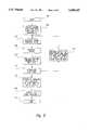
- the pulsatile waveform measured in equations (3) and (4)may resemble the waveform illustrated in the example of FIG. 7A. If the detected signals have a small amount of noise (e.g., r*(t)+n(t)), the pulsatile waveform measured in equations (3) and (4) may resemble the waveform illustrated in the example of FIG. 7B. If the detected signals contain only noise (e.g., n(t)), the pulsatile waveform measured in equations (3) and (4) may resemble the waveform illustrated in the example of FIG. 7C. It should be noted that the waveform of FIG. 7B is more complex than that of FIG.
- FIG. 7Abecause the noise in FIG. 7B tends to add complexity to the overall waveform relative to a normal S P O 2 waveform.
- the waveform of FIG. 7Cis more complex than that of FIG. 7B due to the significant increase in noise in FIG. 7C.
- FDdenotes the "fractal dimension.”
- Euclidean geometryhas long defined objects in space using integer dimensions, such as a one dimensional line, a two dimensional plane, and a three dimensional cube.
- Mathematicianshave recently developed the concept of real numbers for dimensions rather than the more limited Euclidean concept of integer dimensions.
- a mathematical equation plotted on the surface of a piece of papermay not occupy the entire two dimensional plane defined by the surface of the paper. The mathematical equation may, therefore, be considered to occupy a fraction of the two dimensional plane, such as 1.3.
- the term fractal dimensionrefers to the portion of the Euclidean dimensional space occupied by a particular object.
- the present inventionprovides analysis techniques based on the complexity of measured signals.
- One convenient technique used to determine the complexity of the measured signalsis a fractal dimension associated with the measured signals.
- fractal dimensionsprovide a quantitative indication of the complexity of the measured signals.
- the present inventionapplies the fundamental concepts of fractal analysis to physiologic waveforms.
- equation (17)states that the fractal dimension FD of the true signal r*(t) is less than or equal to the fractal dimension FD of the noise signal n(t).
- the present inventionuses fractal analysis to determine the complexity of waveforms based on the premise that the true waveform with no noise will have the least complexity.
- the fractal dimension FDis a type of control signal that can be used to enhance the desired physiological signal.
- Fractal dimensionsare well known and need not be discussed in greater detail herein.
- the study of fractal dimensionsis discussed in The Fractal Geometry of Nature, by B. Mandelbrot, Freeman Press, New York, 1983.
- the study of fractal analysis in physiologic waveformsis described in Fractals and the Analysis of Waveforms, by M. J. Katz, Computers In Biology and Medicine, Vol. 18(3), pp. 145-56, 1988.
- Katzdescribes physiologic waveforms as a special case of Mandelbrot's analysis because of the time dependency of the waveforms.
- the equations used hereinare derived from Katz's article. However, those skilled in that art will recognize that any formula that can be used to derive the fractal value can be used with the present invention.
- Equation (18)gives a time varying signal function for every value of ⁇ . If one assumes that R(t) and r(t) are normalized AC signals, it is possible to restrict the value of the variable ⁇ to the range from 0.3 to 3.0 and show that equation (18) contains all possible signal solutions. For the special cases in which the variable ⁇ is equal to ⁇ or ⁇ , equation (18) simplifies to the following equations:
- ⁇is defined over the range from 0.3 to 3.0.
- the first intervalis discarded and the divide and conquer process is repeated on the second interval.
- the location of the maximum and/or minimumcan be determined to any degree of accuracy by selecting the minimum size for the subdivided interval.
- the divide and conquer techniqueis well known and need not be described in greater detail. There are other well-known techniques for detecting the maximum and minimum values of the fractal dimension function FDs( ⁇ ). The present invention is not limited by the particular technique used to locate the maximum and minimum values.
- the fractal analyzer 102determines the values for ⁇ and ⁇ based on the fractal complexity of the measured signals R(t) and r(t).
- the values for the ( ⁇ , ⁇ ) pairsmay be accumulated for a predetermined time and subjected to further statistical analysis by the statistical analyzer 104 (see FIG. 6) to select the best value for ⁇ .
- the mean value of ⁇can be determined over a predetermined period of time and used as the best value for ⁇ .
- Other forms of statistical analysis known to those of ordinary skill in the artcan also be applied to select the best value for ⁇ .
- the best value for ⁇is then used as the index to the look-up table 14 (see FIG. 6) to determine the arterial oxygen saturation S P O 2 for the patient.
- a peak S P O 2 valuecan also be determined over time using the S P O 2 peak detector 108 (see FIG. 6).
- the system 100collects patient data.
- the system 100collects 500 data points in a data window, which includes 2-4 heartbeats. If there are less than 2 heartbeats in the data window, there may be insufficient data to properly analyze the signals. Conversely, having a large data window that includes more than 4 heartbeats generally does not provide additional information, and the computational complexity increases significantly as the size of the data window is extended. Therefore, a data window of 500 data points typically includes the 2-4 heartbeats.
- the fractal analyzer 102calculates the set of signal functions S(t, ⁇ ) for the collected data.
- the fractal analyzer 102calculates the fractal dimension functions FDs( ⁇ ) over the range of ⁇ from 0.3 to 3.0.
- the fractal analyzer 102finds the maximum and minimum values for the fractal dimension functions.
- the statistical analyzer 104accumulates the ( ⁇ , ⁇ ) pairs.
- step 214the system 100 discards the oldest 100 data points and adds 100 new data points to create a new 500 point data window. The system then returns to step 204 to calculate new signal functions S(t, ⁇ ) for the new 500 point data window.
- the system 100uses a sliding data window to determine the arterial oxygen saturation.
- the statistical analyzer 104is performing a statistical analysis of the accumulated ( ⁇ , ⁇ ) pairs in step 218. The statistical analyzer selects the best ⁇ in step 218.
- step 220the system 100 computes the S P O 2 using the selected ⁇ . As previously discussed, the selected ⁇ is used as an index to the look-up table 14 (see FIG. 6) to determine the S P O 2 for the patient.
- the systemends the analysis in step 222.
- the fractal analysis techniques described aboveprovide a reliable system and method for the determination of blood oxygen saturation even in the presence of significant amounts of noise.
- certain assumptions that have been madeare not correct under all real life circumstances. For example, the assumption that the true signal and the noise signal are uncorrelated is not always true.
- the operation of the system 100 for each of the categoriesis described below.
- the most common caseis category (1) where the signal is mixed with some small amount of motion artifact.
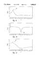
- the fractal dimension function FDs( ⁇ )has a maximum 250 at the point where ⁇ is equal to the value of ⁇ , which is equal to approximately 0.55 in the example illustrated in the graph of FIG. 9.
- the fractal dimension function FDs( ⁇ ), illustrated in the graph of FIG. 10,has a relatively high value except at the point where ⁇ is equal to the value of ⁇ where the desired arterial signal is found.
- the graph of FIG. 10has a minimum 254 at the point where ⁇ is equal to the value of ⁇ , which is equal to approximately 1.5 in the example of FIG. 10.
- the artifact noise signalwill be approximately equal in strength to the desired arterial signal, which corresponds to category (3) above.
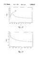
- the data windowtends to include distinguishable maximum and minimum values for the fractal dimension function FDs( ⁇ ), as illustrated in the graph of FIG. 11.
- the fractal dimension function FDs( ⁇ )has a maximum 256 at the point where ⁇ is equal to the value of ⁇ , which is equal to approximately 0.5 in the example of FIG. 11, and a minimum 258 at the point where ⁇ is equal to the value of ⁇ , which is equal to approximately 1.35 in the example of FIG. 11.
- the curve of FIG. 11does not contain sharp peaks for the maximum and minimum values, it is nonetheless possible to determine the maximum and minimum values for the fractal dimension function FDs( ⁇ ).
- ⁇ and/or ⁇ valuesmay not exist is a measurement cycle in which there is no arterial signal, category (5) above. This occurs only in the special case in which the sensor 2 (see FIG. 6) is off of the patient or is unplugged from the rest of the system 100. This is another unusual case in which equations (9)-(13) and (16) are no longer valid because there is no arterial signal. As illustrated in FIG. 13, the fractal dimension function FDs( ⁇ ) behaves differently from that of the other four categories discussed above. The fractal dimension function FDs( ⁇ ) in category (5) produces a smooth curve without any maxima or minima.
- This conditiondoes not produce blood oxygen data, but can be used to detect a "probe off patient” condition and provide an indication to the user.
- the analysisdemonstrates that the fractal dimension method may not produce ⁇ , ⁇ values for every data set, depending on the actual signal content.
- Equation (12)is used as the reference signal 17 to represent the noise n(t) and is varied over the known physiological range for ⁇ .
- the measured signal r(t)which is the sum of the true intensity r*(t) and the noise signal n(t), is applied to the signal input 16 of the adaptive signal processor 15.
- the summer output 19is used as a control signal to adjust the adaptive filter 18.
- the fractal analyzer 102analyzes the summer output 21 of the adaptive signal processor 15 in the manner previously described to determine maximum and minimum fractal values corresponding to ⁇ and ⁇ , respectively.
- the adaptive signal processor 15can be configured in different ways other than the example illustrated in FIG. 3. However, the principles of the present invention can be readily applied to other configurations of the adaptive signal processor 15.
- the output of the fractal analyzer 102(see FIG. 6) is used to select the proper reference signal 17.
- a third light source(not shown) may be added to produce a third wavelength in the sensor 2 (see FIG. 5).
- Three ratios of light intensitiese.g., ratio of light source one to light source two, ratio of light source one to light source three, and ratio of light source two to light source three
- the three ratioscan be independently used to derive both the arterial oxygen saturation and the arterial carboxyhemoglobin saturation period.
- the present inventionis also not limited solely to the use of optical sensors.
- Electrical sensorsmay derive physiological signals that can be processed according to the principles of the present invention.
- electrical sensorscan be used to derive a noise-free ECG signal.
- the electrical sensorseach derive an ECG signal and the ratios of the ECG signals may be used to derive a noise-free version of the true ECG signal.
- the fractal analysis of the present inventioncan derive noise-free physiological signals in a variety of conditions.
- the present inventionis described herein using the example of pulse oximetry.
- the minimum fractal dimension FDcorresponds to the value of ⁇ .
- an ECG signalis often contaminated by interference from a low frequency respiratory signal.
- the minimum fractal dimension FDmay correspond to the respiratory signal rather than the desired ECG signal.
- the maximum fractal dimension FDmay correspond to the desired ECG signal.
Landscapes
- Health & Medical Sciences (AREA)
- Physics & Mathematics (AREA)
- Life Sciences & Earth Sciences (AREA)
- Biomedical Technology (AREA)
- Medical Informatics (AREA)
- Biophysics (AREA)
- Pathology (AREA)
- Engineering & Computer Science (AREA)
- Spectroscopy & Molecular Physics (AREA)
- Heart & Thoracic Surgery (AREA)
- Optics & Photonics (AREA)
- Molecular Biology (AREA)
- Surgery (AREA)
- Animal Behavior & Ethology (AREA)
- General Health & Medical Sciences (AREA)
- Public Health (AREA)
- Veterinary Medicine (AREA)
- Measurement Of The Respiration, Hearing Ability, Form, And Blood Characteristics Of Living Organisms (AREA)
Abstract
Description
R=R*+N (1)
r=r*+n (2)
R(t)=R*(t)+N(t) (3)
r(t)=r*(t)+n(t) (4)
FD(r*(t))<FD(n(t)) (17)
S(t,θ)=n(t) θ=α (19)
S(t,θ)=r*(t) θ=β (20)
FDs(θ)≡FD(n(t))=maximum, θ=α (22)
FDs(θ)≡FD(r*(t))=minimum, θ=β (23)
Claims (30)
Priority Applications (1)
| Application Number | Priority Date | Filing Date | Title |
|---|---|---|---|
| US08/559,846US5588427A (en) | 1995-11-20 | 1995-11-20 | Enhancement of physiological signals using fractal analysis |
Applications Claiming Priority (1)
| Application Number | Priority Date | Filing Date | Title |
|---|---|---|---|
| US08/559,846US5588427A (en) | 1995-11-20 | 1995-11-20 | Enhancement of physiological signals using fractal analysis |
Publications (1)
| Publication Number | Publication Date |
|---|---|
| US5588427Atrue US5588427A (en) | 1996-12-31 |
Family
ID=24235275
Family Applications (1)
| Application Number | Title | Priority Date | Filing Date |
|---|---|---|---|
| US08/559,846Expired - LifetimeUS5588427A (en) | 1995-11-20 | 1995-11-20 | Enhancement of physiological signals using fractal analysis |
Country Status (1)
| Country | Link |
|---|---|
| US (1) | US5588427A (en) |
Cited By (138)
| Publication number | Priority date | Publication date | Assignee | Title |
|---|---|---|---|---|
| US6002952A (en)* | 1997-04-14 | 1999-12-14 | Masimo Corporation | Signal processing apparatus and method |
| DE19831424A1 (en)* | 1998-07-14 | 2000-02-03 | Mbr Gmbh | Spectroscopic method to determine concentration of substance distributed in light scattering medium, e.g. body tissue, using fractal dimension |
| US6393311B1 (en) | 1998-10-15 | 2002-05-21 | Ntc Technology Inc. | Method, apparatus and system for removing motion artifacts from measurements of bodily parameters |
| US6422998B1 (en)* | 1999-09-20 | 2002-07-23 | Ut-Battelle, Llc | Fractal analysis of time varying data |
| US6487439B1 (en)* | 1997-03-17 | 2002-11-26 | Victor N. Skladnev | Glove-mounted hybrid probe for tissue type recognition |
| US6505060B1 (en) | 2000-09-29 | 2003-01-07 | Datex-Ohmeda, Inc. | Method and apparatus for determining pulse oximetry differential values |
| US6515273B2 (en)* | 1999-08-26 | 2003-02-04 | Masimo Corporation | System for indicating the expiration of the useful operating life of a pulse oximetry sensor |
| US20030028086A1 (en)* | 2000-09-29 | 2003-02-06 | Heckel Donald W. | Pulse oximetry method and system with improved motion correction |
| US6519486B1 (en) | 1998-10-15 | 2003-02-11 | Ntc Technology Inc. | Method, apparatus and system for removing motion artifacts from measurements of bodily parameters |
| US6541756B2 (en) | 1991-03-21 | 2003-04-01 | Masimo Corporation | Shielded optical probe having an electrical connector |
| US6542764B1 (en) | 1999-12-01 | 2003-04-01 | Masimo Corporation | Pulse oximeter monitor for expressing the urgency of the patient's condition |
| US20060122520A1 (en)* | 2004-12-07 | 2006-06-08 | Dr. Matthew Banet | Vital sign-monitoring system with multiple optical modules |
| US20060258927A1 (en)* | 1998-10-15 | 2006-11-16 | Edgar Reuben W Jr | Method, apparatus, and system for removing motion artifacts from measurements of bodily parameters |
| US20060258921A1 (en)* | 2003-02-27 | 2006-11-16 | Cardiodigital Limited | Method of analyzing and processing signals |
| US20070073120A1 (en)* | 2005-09-29 | 2007-03-29 | Li Li | System and method for pre-processing waveforms |
| US20070129616A1 (en)* | 2005-12-02 | 2007-06-07 | Borje Rantala | Probe and a method for use with a probe |
| US20070149872A1 (en)* | 2005-12-23 | 2007-06-28 | Shenzhen Mindray Bio-Medical Electronics Co., Ltd. | Method and apparatus for eliminating interference in pulse oxygen measurement |
| US20070260132A1 (en)* | 2006-05-04 | 2007-11-08 | Sterling Bernhard B | Method and apparatus for processing signals reflecting physiological characteristics from multiple sensors |
| US7377794B2 (en) | 2005-03-01 | 2008-05-27 | Masimo Corporation | Multiple wavelength sensor interconnect |
| US20080297764A1 (en)* | 2006-11-13 | 2008-12-04 | Weinmann Gerate Fur Medizin Gmbh + Co. Kg | Sensor for determining body parameters |
| US7477924B2 (en) | 2006-05-02 | 2009-01-13 | Nellcor Puritan Bennett Llc | Medical sensor and technique for using the same |
| US7483731B2 (en) | 2005-09-30 | 2009-01-27 | Nellcor Puritan Bennett Llc | Medical sensor and technique for using the same |
| US7486979B2 (en) | 2005-09-30 | 2009-02-03 | Nellcor Puritan Bennett Llc | Optically aligned pulse oximetry sensor and technique for using the same |
| US7499740B2 (en) | 2004-02-25 | 2009-03-03 | Nellcor Puritan Bennett Llc | Techniques for detecting heart pulses and reducing power consumption in sensors |
| US7522948B2 (en) | 2006-05-02 | 2009-04-21 | Nellcor Puritan Bennett Llc | Medical sensor and technique for using the same |
| US7555327B2 (en) | 2005-09-30 | 2009-06-30 | Nellcor Puritan Bennett Llc | Folding medical sensor and technique for using the same |
| US7574244B2 (en) | 2005-08-08 | 2009-08-11 | Nellcor Puritan Bennett Llc | Compliant diaphragm medical sensor and technique for using the same |
| US7574245B2 (en) | 2006-09-27 | 2009-08-11 | Nellcor Puritan Bennett Llc | Flexible medical sensor enclosure |
| US7590439B2 (en) | 2005-08-08 | 2009-09-15 | Nellcor Puritan Bennett Llc | Bi-stable medical sensor and technique for using the same |
| US7650177B2 (en) | 2005-09-29 | 2010-01-19 | Nellcor Puritan Bennett Llc | Medical sensor for reducing motion artifacts and technique for using the same |
| US7657295B2 (en) | 2005-08-08 | 2010-02-02 | Nellcor Puritan Bennett Llc | Medical sensor and technique for using the same |
| US7658652B2 (en) | 2006-09-29 | 2010-02-09 | Nellcor Puritan Bennett Llc | Device and method for reducing crosstalk |
| US7676253B2 (en) | 2005-09-29 | 2010-03-09 | Nellcor Puritan Bennett Llc | Medical sensor and technique for using the same |
| US7680522B2 (en) | 2006-09-29 | 2010-03-16 | Nellcor Puritan Bennett Llc | Method and apparatus for detecting misapplied sensors |
| US7684842B2 (en) | 2006-09-29 | 2010-03-23 | Nellcor Puritan Bennett Llc | System and method for preventing sensor misuse |
| US7689259B2 (en) | 2000-04-17 | 2010-03-30 | Nellcor Puritan Bennett Llc | Pulse oximeter sensor with piece-wise function |
| US20100094107A1 (en)* | 2008-10-13 | 2010-04-15 | Masimo Corporation | Reflection-detector sensor position indicator |
| US7720516B2 (en) | 1996-10-10 | 2010-05-18 | Nellcor Puritan Bennett Llc | Motion compatible sensor for non-invasive optical blood analysis |
| US20100160796A1 (en)* | 2007-06-12 | 2010-06-24 | Sotera Wireless, Inc. | BODY-WORN SYSTEM FOR MEASURING CONTINUOUS NON-INVASIVE BLOOD PRESSURE (cNIBP) |
| US20100160798A1 (en)* | 2007-06-12 | 2010-06-24 | Sotera Wireless, Inc. | BODY-WORN SYSTEM FOR MEASURING CONTINUOUS NON-INVASIVE BLOOD PRESSURE (cNIBP) |
| US7796403B2 (en) | 2006-09-28 | 2010-09-14 | Nellcor Puritan Bennett Llc | Means for mechanical registration and mechanical-electrical coupling of a faraday shield to a photodetector and an electrical circuit |
| US20100298651A1 (en)* | 2009-05-20 | 2010-11-25 | Triage Wireless, Inc. | Cable system for generating signals for detecting motion and measuring vital signs |
| US20100298661A1 (en)* | 2009-05-20 | 2010-11-25 | Triage Wireless, Inc. | Method for generating alarms/alerts based on a patient's posture and vital signs |
| US20100318146A1 (en)* | 2009-06-10 | 2010-12-16 | Can Cinbis | Tissue Oxygenation Monitoring in Heart Failure |
| US20100317938A1 (en)* | 2009-06-10 | 2010-12-16 | Kuhn Jonathan L | Device and Method for Monitoring of Absolute Oxygen Saturation and Tissue Hemoglobin Concentration |
| US20100317943A1 (en)* | 2009-06-10 | 2010-12-16 | Kuhn Jonathan L | Active Noise Cancellation in an Optical Sensor Signal |
| US20100318149A1 (en)* | 2009-06-10 | 2010-12-16 | Kuhn Jonathan L | Shock Reduction Using Absolute Calibrated Tissue Oxygen Saturation and Total Hemoglobin Volume Fraction |
| US20100317940A1 (en)* | 2009-06-10 | 2010-12-16 | Kuhn Jonathan L | Absolute calibrated tissue oxygen saturation and total hemoglobin volume fraction |
| US20100324389A1 (en)* | 2009-06-17 | 2010-12-23 | Jim Moon | Body-worn pulse oximeter |
| US7869849B2 (en) | 2006-09-26 | 2011-01-11 | Nellcor Puritan Bennett Llc | Opaque, electrically nonconductive region on a medical sensor |
| US7881762B2 (en) | 2005-09-30 | 2011-02-01 | Nellcor Puritan Bennett Llc | Clip-style medical sensor and technique for using the same |
| US7880884B2 (en) | 2008-06-30 | 2011-02-01 | Nellcor Puritan Bennett Llc | System and method for coating and shielding electronic sensor components |
| US7887345B2 (en) | 2008-06-30 | 2011-02-15 | Nellcor Puritan Bennett Llc | Single use connector for pulse oximetry sensors |
| US7890153B2 (en) | 2006-09-28 | 2011-02-15 | Nellcor Puritan Bennett Llc | System and method for mitigating interference in pulse oximetry |
| US7894869B2 (en) | 2007-03-09 | 2011-02-22 | Nellcor Puritan Bennett Llc | Multiple configuration medical sensor and technique for using the same |
| US7899510B2 (en) | 2005-09-29 | 2011-03-01 | Nellcor Puritan Bennett Llc | Medical sensor and technique for using the same |
| US20110066018A1 (en)* | 2009-09-11 | 2011-03-17 | Kuhn Jonathan L | Method and apparatus for post-shock evaluation using tissue oxygenation measurements |
| US20110066044A1 (en)* | 2009-09-15 | 2011-03-17 | Jim Moon | Body-worn vital sign monitor |
| US20110066008A1 (en)* | 2009-09-14 | 2011-03-17 | Matt Banet | Body-worn monitor for measuring respiration rate |
| US20110066009A1 (en)* | 2009-09-15 | 2011-03-17 | Jim Moon | Body-worn vital sign monitor |
| US20110066043A1 (en)* | 2009-09-14 | 2011-03-17 | Matt Banet | System for measuring vital signs during hemodialysis |
| US20110066045A1 (en)* | 2009-09-15 | 2011-03-17 | Jim Moon | Body-worn vital sign monitor |
| US20110087121A1 (en)* | 2009-10-13 | 2011-04-14 | Siemens Medical Solutions Usa, Inc. | System for Continuous cardiac pathology detection and characterization |
| US20110224508A1 (en)* | 2010-03-10 | 2011-09-15 | Sotera Wireless, Inc. | Body-worn vital sign monitor |
| US8062221B2 (en) | 2005-09-30 | 2011-11-22 | Nellcor Puritan Bennett Llc | Sensor for tissue gas detection and technique for using the same |
| US8068891B2 (en) | 2006-09-29 | 2011-11-29 | Nellcor Puritan Bennett Llc | Symmetric LED array for pulse oximetry |
| US8071935B2 (en) | 2008-06-30 | 2011-12-06 | Nellcor Puritan Bennett Llc | Optical detector with an overmolded faraday shield |
| US8073518B2 (en) | 2006-05-02 | 2011-12-06 | Nellcor Puritan Bennett Llc | Clip-style medical sensor and technique for using the same |
| US8070508B2 (en) | 2007-12-31 | 2011-12-06 | Nellcor Puritan Bennett Llc | Method and apparatus for aligning and securing a cable strain relief |
| US8092379B2 (en) | 2005-09-29 | 2012-01-10 | Nellcor Puritan Bennett Llc | Method and system for determining when to reposition a physiological sensor |
| US8092993B2 (en) | 2007-12-31 | 2012-01-10 | Nellcor Puritan Bennett Llc | Hydrogel thin film for use as a biosensor |
| US8112375B2 (en) | 2008-03-31 | 2012-02-07 | Nellcor Puritan Bennett Llc | Wavelength selection and outlier detection in reduced rank linear models |
| US20120059267A1 (en)* | 2010-08-26 | 2012-03-08 | Masimo Corporation | Blood pressure measurement system |
| US8133176B2 (en) | 1999-04-14 | 2012-03-13 | Tyco Healthcare Group Lp | Method and circuit for indicating quality and accuracy of physiological measurements |
| US8145288B2 (en) | 2006-08-22 | 2012-03-27 | Nellcor Puritan Bennett Llc | Medical sensor for reducing signal artifacts and technique for using the same |
| US8175667B2 (en) | 2006-09-29 | 2012-05-08 | Nellcor Puritan Bennett Llc | Symmetric LED array for pulse oximetry |
| US8175671B2 (en) | 2006-09-22 | 2012-05-08 | Nellcor Puritan Bennett Llc | Medical sensor for reducing signal artifacts and technique for using the same |
| US8190224B2 (en) | 2006-09-22 | 2012-05-29 | Nellcor Puritan Bennett Llc | Medical sensor for reducing signal artifacts and technique for using the same |
| US8199007B2 (en) | 2007-12-31 | 2012-06-12 | Nellcor Puritan Bennett Llc | Flex circuit snap track for a biometric sensor |
| US8219170B2 (en) | 2006-09-20 | 2012-07-10 | Nellcor Puritan Bennett Llc | System and method for practicing spectrophotometry using light emitting nanostructure devices |
| US8224412B2 (en) | 2000-04-17 | 2012-07-17 | Nellcor Puritan Bennett Llc | Pulse oximeter sensor with piece-wise function |
| US8221319B2 (en) | 2009-03-25 | 2012-07-17 | Nellcor Puritan Bennett Llc | Medical device for assessing intravascular blood volume and technique for using the same |
| US8233954B2 (en) | 2005-09-30 | 2012-07-31 | Nellcor Puritan Bennett Llc | Mucosal sensor for the assessment of tissue and blood constituents and technique for using the same |
| US8260391B2 (en) | 2005-09-12 | 2012-09-04 | Nellcor Puritan Bennett Llc | Medical sensor for reducing motion artifacts and technique for using the same |
| US8265724B2 (en) | 2007-03-09 | 2012-09-11 | Nellcor Puritan Bennett Llc | Cancellation of light shunting |
| US8280469B2 (en) | 2007-03-09 | 2012-10-02 | Nellcor Puritan Bennett Llc | Method for detection of aberrant tissue spectra |
| US8311601B2 (en) | 2009-06-30 | 2012-11-13 | Nellcor Puritan Bennett Llc | Reflectance and/or transmissive pulse oximeter |
| US8346328B2 (en) | 2007-12-21 | 2013-01-01 | Covidien Lp | Medical sensor and technique for using the same |
| US8352004B2 (en) | 2007-12-21 | 2013-01-08 | Covidien Lp | Medical sensor and technique for using the same |
| US8364220B2 (en) | 2008-09-25 | 2013-01-29 | Covidien Lp | Medical sensor and technique for using the same |
| US8366613B2 (en) | 2007-12-26 | 2013-02-05 | Covidien Lp | LED drive circuit for pulse oximetry and method for using same |
| US8391941B2 (en) | 2009-07-17 | 2013-03-05 | Covidien Lp | System and method for memory switching for multiple configuration medical sensor |
| US8396527B2 (en) | 2006-09-22 | 2013-03-12 | Covidien Lp | Medical sensor for reducing signal artifacts and technique for using the same |
| US8417310B2 (en) | 2009-08-10 | 2013-04-09 | Covidien Lp | Digital switching in multi-site sensor |
| US8417309B2 (en) | 2008-09-30 | 2013-04-09 | Covidien Lp | Medical sensor |
| US8423112B2 (en) | 2008-09-30 | 2013-04-16 | Covidien Lp | Medical sensor and technique for using the same |
| US8428675B2 (en) | 2009-08-19 | 2013-04-23 | Covidien Lp | Nanofiber adhesives used in medical devices |
| US8433383B2 (en) | 2001-10-12 | 2013-04-30 | Covidien Lp | Stacked adhesive optical sensor |
| US8437822B2 (en) | 2008-03-28 | 2013-05-07 | Covidien Lp | System and method for estimating blood analyte concentration |
| US8442608B2 (en) | 2007-12-28 | 2013-05-14 | Covidien Lp | System and method for estimating physiological parameters by deconvolving artifacts |
| US8452364B2 (en) | 2007-12-28 | 2013-05-28 | Covidien LLP | System and method for attaching a sensor to a patient's skin |
| US8452366B2 (en) | 2009-03-16 | 2013-05-28 | Covidien Lp | Medical monitoring device with flexible circuitry |
| US8483790B2 (en) | 2002-10-18 | 2013-07-09 | Covidien Lp | Non-adhesive oximeter sensor for sensitive skin |
| US8509869B2 (en) | 2009-05-15 | 2013-08-13 | Covidien Lp | Method and apparatus for detecting and analyzing variations in a physiologic parameter |
| US8505821B2 (en) | 2009-06-30 | 2013-08-13 | Covidien Lp | System and method for providing sensor quality assurance |
| US8577434B2 (en) | 2007-12-27 | 2013-11-05 | Covidien Lp | Coaxial LED light sources |
| US8634891B2 (en) | 2009-05-20 | 2014-01-21 | Covidien Lp | Method and system for self regulation of sensor component contact pressure |
| US8747330B2 (en) | 2010-04-19 | 2014-06-10 | Sotera Wireless, Inc. | Body-worn monitor for measuring respiratory rate |
| US8781544B2 (en) | 2007-03-27 | 2014-07-15 | Cercacor Laboratories, Inc. | Multiple wavelength optical sensor |
| US8801613B2 (en) | 2009-12-04 | 2014-08-12 | Masimo Corporation | Calibration for multi-stage physiological monitors |
| US8888700B2 (en) | 2010-04-19 | 2014-11-18 | Sotera Wireless, Inc. | Body-worn monitor for measuring respiratory rate |
| US8897850B2 (en) | 2007-12-31 | 2014-11-25 | Covidien Lp | Sensor with integrated living hinge and spring |
| US8914088B2 (en) | 2008-09-30 | 2014-12-16 | Covidien Lp | Medical sensor and technique for using the same |
| US8965471B2 (en) | 2007-04-21 | 2015-02-24 | Cercacor Laboratories, Inc. | Tissue profile wellness monitor |
| US8979765B2 (en) | 2010-04-19 | 2015-03-17 | Sotera Wireless, Inc. | Body-worn monitor for measuring respiratory rate |
| US9010634B2 (en) | 2009-06-30 | 2015-04-21 | Covidien Lp | System and method for linking patient data to a patient and providing sensor quality assurance |
| US9173594B2 (en) | 2010-04-19 | 2015-11-03 | Sotera Wireless, Inc. | Body-worn monitor for measuring respiratory rate |
| US9173593B2 (en) | 2010-04-19 | 2015-11-03 | Sotera Wireless, Inc. | Body-worn monitor for measuring respiratory rate |
| US9339209B2 (en) | 2010-04-19 | 2016-05-17 | Sotera Wireless, Inc. | Body-worn monitor for measuring respiratory rate |
| US9364158B2 (en) | 2010-12-28 | 2016-06-14 | Sotera Wirless, Inc. | Body-worn system for continuous, noninvasive measurement of cardiac output, stroke volume, cardiac power, and blood pressure |
| US9439574B2 (en) | 2011-02-18 | 2016-09-13 | Sotera Wireless, Inc. | Modular wrist-worn processor for patient monitoring |
| US9560998B2 (en) | 2006-10-12 | 2017-02-07 | Masimo Corporation | System and method for monitoring the life of a physiological sensor |
| US9795739B2 (en) | 2009-05-20 | 2017-10-24 | Masimo Corporation | Hemoglobin display and patient treatment |
| US9839381B1 (en) | 2009-11-24 | 2017-12-12 | Cercacor Laboratories, Inc. | Physiological measurement system with automatic wavelength adjustment |
| US20180116568A1 (en)* | 2016-10-27 | 2018-05-03 | Nihon Kohden Corporation | Medical photometer and medical photometer control method |
| US20180116567A1 (en)* | 2016-10-27 | 2018-05-03 | Nihon Kohden Corporation | Medical photometer and medical photometer control method |
| US10357187B2 (en) | 2011-02-18 | 2019-07-23 | Sotera Wireless, Inc. | Optical sensor for measuring physiological properties |
| US10420476B2 (en) | 2009-09-15 | 2019-09-24 | Sotera Wireless, Inc. | Body-worn vital sign monitor |
| US11191485B2 (en) | 2006-06-05 | 2021-12-07 | Masimo Corporation | Parameter upgrade system |
| US11253169B2 (en) | 2009-09-14 | 2022-02-22 | Sotera Wireless, Inc. | Body-worn monitor for measuring respiration rate |
| US11330988B2 (en) | 2007-06-12 | 2022-05-17 | Sotera Wireless, Inc. | Body-worn system for measuring continuous non-invasive blood pressure (cNIBP) |
| US11607152B2 (en) | 2007-06-12 | 2023-03-21 | Sotera Wireless, Inc. | Optical sensors for use in vital sign monitoring |
| US11793466B2 (en) | 2016-08-12 | 2023-10-24 | Koninklijke Philips N.V. | Sensor device and method, device and method for communication with the sensor device |
| US11896350B2 (en) | 2009-05-20 | 2024-02-13 | Sotera Wireless, Inc. | Cable system for generating signals for detecting motion and measuring vital signs |
| US12029586B2 (en) | 2006-10-12 | 2024-07-09 | Masimo Corporation | Oximeter probe off indicator defining probe off space |
| US12121364B2 (en) | 2009-09-14 | 2024-10-22 | Sotera Wireless, Inc. | Body-worn monitor for measuring respiration rate |
| US12156743B2 (en) | 2009-09-15 | 2024-12-03 | Sotera Wireless, Inc. | Body-worn vital sign monitor |
| US12245852B2 (en) | 2007-06-12 | 2025-03-11 | Sotera Wireless, Inc. | Optical sensors for use in vital sign monitoring |
Citations (3)
| Publication number | Priority date | Publication date | Assignee | Title |
|---|---|---|---|---|
| US5040539A (en)* | 1989-05-12 | 1991-08-20 | The United States Of America | Pulse oximeter for diagnosis of dental pulp pathology |
| US5277181A (en)* | 1991-12-12 | 1994-01-11 | Vivascan Corporation | Noninvasive measurement of hematocrit and hemoglobin content by differential optical analysis |
| US5482036A (en)* | 1991-03-07 | 1996-01-09 | Masimo Corporation | Signal processing apparatus and method |
- 1995
- 1995-11-20USUS08/559,846patent/US5588427A/ennot_activeExpired - Lifetime
Patent Citations (3)
| Publication number | Priority date | Publication date | Assignee | Title |
|---|---|---|---|---|
| US5040539A (en)* | 1989-05-12 | 1991-08-20 | The United States Of America | Pulse oximeter for diagnosis of dental pulp pathology |
| US5482036A (en)* | 1991-03-07 | 1996-01-09 | Masimo Corporation | Signal processing apparatus and method |
| US5277181A (en)* | 1991-12-12 | 1994-01-11 | Vivascan Corporation | Noninvasive measurement of hematocrit and hemoglobin content by differential optical analysis |
Cited By (357)
| Publication number | Priority date | Publication date | Assignee | Title |
|---|---|---|---|---|
| US6541756B2 (en) | 1991-03-21 | 2003-04-01 | Masimo Corporation | Shielded optical probe having an electrical connector |
| US7132641B2 (en) | 1991-03-21 | 2006-11-07 | Masimo Corporation | Shielded optical probe having an electrical connector |
| US8649839B2 (en) | 1996-10-10 | 2014-02-11 | Covidien Lp | Motion compatible sensor for non-invasive optical blood analysis |
| US7720516B2 (en) | 1996-10-10 | 2010-05-18 | Nellcor Puritan Bennett Llc | Motion compatible sensor for non-invasive optical blood analysis |
| US6487439B1 (en)* | 1997-03-17 | 2002-11-26 | Victor N. Skladnev | Glove-mounted hybrid probe for tissue type recognition |
| US8180420B2 (en) | 1997-04-14 | 2012-05-15 | Masimo Corporation | Signal processing apparatus and method |
| US8888708B2 (en) | 1997-04-14 | 2014-11-18 | Masimo Corporation | Signal processing apparatus and method |
| US9289167B2 (en) | 1997-04-14 | 2016-03-22 | Masimo Corporation | Signal processing apparatus and method |
| US6699194B1 (en) | 1997-04-14 | 2004-03-02 | Masimo Corporation | Signal processing apparatus and method |
| US6067462A (en)* | 1997-04-14 | 2000-05-23 | Masimo Corporation | Signal processing apparatus and method |
| US6002952A (en)* | 1997-04-14 | 1999-12-14 | Masimo Corporation | Signal processing apparatus and method |
| US8190227B2 (en) | 1997-04-14 | 2012-05-29 | Masimo Corporation | Signal processing apparatus and method |
| DE19831424C2 (en)* | 1998-07-14 | 2000-12-28 | Mbr Gmbh | Spectroscopic method for determining the concentration of a substance distributed in a scattering medium |
| DE19831424A1 (en)* | 1998-07-14 | 2000-02-03 | Mbr Gmbh | Spectroscopic method to determine concentration of substance distributed in light scattering medium, e.g. body tissue, using fractal dimension |
| US6519486B1 (en) | 1998-10-15 | 2003-02-11 | Ntc Technology Inc. | Method, apparatus and system for removing motion artifacts from measurements of bodily parameters |
| US6810277B2 (en) | 1998-10-15 | 2004-10-26 | Ric Investments, Inc. | Method, apparatus and system for removing motion artifacts from measurements of bodily parameters |
| US6393311B1 (en) | 1998-10-15 | 2002-05-21 | Ntc Technology Inc. | Method, apparatus and system for removing motion artifacts from measurements of bodily parameters |
| US7991448B2 (en) | 1998-10-15 | 2011-08-02 | Philips Electronics North America Corporation | Method, apparatus, and system for removing motion artifacts from measurements of bodily parameters |
| US20060258927A1 (en)* | 1998-10-15 | 2006-11-16 | Edgar Reuben W Jr | Method, apparatus, and system for removing motion artifacts from measurements of bodily parameters |
| US7072702B2 (en) | 1998-10-15 | 2006-07-04 | Ric Investments, Llc | Method, apparatus and system for removing motion artifacts from measurements of bodily parameters |
| US8133176B2 (en) | 1999-04-14 | 2012-03-13 | Tyco Healthcare Group Lp | Method and circuit for indicating quality and accuracy of physiological measurements |
| US6979812B2 (en) | 1999-08-26 | 2005-12-27 | Masimo Corporation | Systems and methods for indicating an amount of use of a sensor |
| US8399822B2 (en) | 1999-08-26 | 2013-03-19 | Masimo Corporation | Systems and methods for indicating an amount of use of a sensor |
| US7910875B2 (en) | 1999-08-26 | 2011-03-22 | Masimo Corporation | Systems and methods for indicating an amount of use of a sensor |
| US6861639B2 (en) | 1999-08-26 | 2005-03-01 | Masimo Corporation | Systems and methods for indicating an amount of use of a sensor |
| US7186966B2 (en) | 1999-08-26 | 2007-03-06 | Masimo Corporation | Amount of use tracking device and method for medical product |
| US6515273B2 (en)* | 1999-08-26 | 2003-02-04 | Masimo Corporation | System for indicating the expiration of the useful operating life of a pulse oximetry sensor |
| US20030111592A1 (en)* | 1999-08-26 | 2003-06-19 | Ammar Al-Ali | Systems and methods for indicating an amount of use of a sensor |
| US6422998B1 (en)* | 1999-09-20 | 2002-07-23 | Ut-Battelle, Llc | Fractal analysis of time varying data |
| US6542764B1 (en) | 1999-12-01 | 2003-04-01 | Masimo Corporation | Pulse oximeter monitor for expressing the urgency of the patient's condition |
| US8078246B2 (en) | 2000-04-17 | 2011-12-13 | Nellcor Puritan Bennett Llc | Pulse oximeter sensor with piece-wise function |
| US7689259B2 (en) | 2000-04-17 | 2010-03-30 | Nellcor Puritan Bennett Llc | Pulse oximeter sensor with piece-wise function |
| US8224412B2 (en) | 2000-04-17 | 2012-07-17 | Nellcor Puritan Bennett Llc | Pulse oximeter sensor with piece-wise function |
| EP1320321A4 (en)* | 2000-09-29 | 2006-10-04 | Datex Ohmeda Inc | Pulse oximetry method and system with improved motion correction |
| US20030028086A1 (en)* | 2000-09-29 | 2003-02-06 | Heckel Donald W. | Pulse oximetry method and system with improved motion correction |
| US6839582B2 (en) | 2000-09-29 | 2005-01-04 | Datex-Ohmeda, Inc. | Pulse oximetry method and system with improved motion correction |
| US6505060B1 (en) | 2000-09-29 | 2003-01-07 | Datex-Ohmeda, Inc. | Method and apparatus for determining pulse oximetry differential values |
| US8433383B2 (en) | 2001-10-12 | 2013-04-30 | Covidien Lp | Stacked adhesive optical sensor |
| US8483790B2 (en) | 2002-10-18 | 2013-07-09 | Covidien Lp | Non-adhesive oximeter sensor for sensitive skin |
| US20060258921A1 (en)* | 2003-02-27 | 2006-11-16 | Cardiodigital Limited | Method of analyzing and processing signals |
| US10182764B2 (en) | 2003-02-27 | 2019-01-22 | Nellcor Puritan Bennett Ireland | Method of analyzing and processing signals |
| US9192336B2 (en) | 2003-02-27 | 2015-11-24 | Nellcor Puritan Bennett Ireland | Method of analyzing and processing signals |
| US9198616B2 (en) | 2003-02-27 | 2015-12-01 | Nellcor Puritan Bennett Ireland | Method of analyzing and processing signals |
| US9220459B2 (en) | 2003-02-27 | 2015-12-29 | Nellcor Puritan Bennett Ireland | Method of analyzing and processing signals |
| US9220460B2 (en) | 2003-02-27 | 2015-12-29 | Nellcor Puritan Bennett Ireland | Method of analyzing and processing signals |
| WO2004075746A3 (en)* | 2003-02-27 | 2007-02-08 | Cardiodigital Ltd | Method and system for analysing and processing ph0t0plethysmogram signals using wavelet transform |
| US8255029B2 (en) | 2003-02-27 | 2012-08-28 | Nellcor Puritan Bennett Llc | Method of analyzing and processing signals |
| US7499740B2 (en) | 2004-02-25 | 2009-03-03 | Nellcor Puritan Bennett Llc | Techniques for detecting heart pulses and reducing power consumption in sensors |
| US20060122520A1 (en)* | 2004-12-07 | 2006-06-08 | Dr. Matthew Banet | Vital sign-monitoring system with multiple optical modules |
| US8385996B2 (en) | 2005-03-01 | 2013-02-26 | Cercacor Laboratories, Inc. | Multiple wavelength sensor emitters |
| US8718735B2 (en) | 2005-03-01 | 2014-05-06 | Cercacor Laboratories, Inc. | Physiological parameter confidence measure |
| US9351675B2 (en) | 2005-03-01 | 2016-05-31 | Cercacor Laboratories, Inc. | Noninvasive multi-parameter patient monitor |
| US9241662B2 (en) | 2005-03-01 | 2016-01-26 | Cercacor Laboratories, Inc. | Configurable physiological measurement system |
| US9549696B2 (en) | 2005-03-01 | 2017-01-24 | Cercacor Laboratories, Inc. | Physiological parameter confidence measure |
| US9750443B2 (en) | 2005-03-01 | 2017-09-05 | Cercacor Laboratories, Inc. | Multiple wavelength sensor emitters |
| US7377794B2 (en) | 2005-03-01 | 2008-05-27 | Masimo Corporation | Multiple wavelength sensor interconnect |
| US8483787B2 (en) | 2005-03-01 | 2013-07-09 | Cercacor Laboratories, Inc. | Multiple wavelength sensor drivers |
| US12283374B2 (en) | 2005-03-01 | 2025-04-22 | Willow Laboratories, Inc. | Noninvasive multi-parameter patient monitor |
| US9167995B2 (en) | 2005-03-01 | 2015-10-27 | Cercacor Laboratories, Inc. | Physiological parameter confidence measure |
| US10123726B2 (en) | 2005-03-01 | 2018-11-13 | Cercacor Laboratories, Inc. | Configurable physiological measurement system |
| US7729733B2 (en) | 2005-03-01 | 2010-06-01 | Masimo Laboratories, Inc. | Configurable physiological measurement system |
| US10251585B2 (en) | 2005-03-01 | 2019-04-09 | Cercacor Laboratories, Inc. | Noninvasive multi-parameter patient monitor |
| US9131882B2 (en) | 2005-03-01 | 2015-09-15 | Cercacor Laboratories, Inc. | Noninvasive multi-parameter patient monitor |
| US8224411B2 (en) | 2005-03-01 | 2012-07-17 | Masimo Laboratories, Inc. | Noninvasive multi-parameter patient monitor |
| US8581732B2 (en) | 2005-03-01 | 2013-11-12 | Carcacor Laboratories, Inc. | Noninvasive multi-parameter patient monitor |
| US8190223B2 (en) | 2005-03-01 | 2012-05-29 | Masimo Laboratories, Inc. | Noninvasive multi-parameter patient monitor |
| US7647083B2 (en) | 2005-03-01 | 2010-01-12 | Masimo Laboratories, Inc. | Multiple wavelength sensor equalization |
| US10327683B2 (en) | 2005-03-01 | 2019-06-25 | Cercacor Laboratories, Inc. | Multiple wavelength sensor emitters |
| US7596398B2 (en) | 2005-03-01 | 2009-09-29 | Masimo Laboratories, Inc. | Multiple wavelength sensor attachment |
| US7761127B2 (en) | 2005-03-01 | 2010-07-20 | Masimo Laboratories, Inc. | Multiple wavelength sensor substrate |
| US7764982B2 (en) | 2005-03-01 | 2010-07-27 | Masimo Laboratories, Inc. | Multiple wavelength sensor emitters |
| US8301217B2 (en) | 2005-03-01 | 2012-10-30 | Cercacor Laboratories, Inc. | Multiple wavelength sensor emitters |
| US8130105B2 (en) | 2005-03-01 | 2012-03-06 | Masimo Laboratories, Inc. | Noninvasive multi-parameter patient monitor |
| US8634889B2 (en) | 2005-03-01 | 2014-01-21 | Cercacor Laboratories, Inc. | Configurable physiological measurement system |
| US12230393B2 (en) | 2005-03-01 | 2025-02-18 | Willow Laboratories, Inc. | Multiple wavelength sensor emitters |
| US10856788B2 (en) | 2005-03-01 | 2020-12-08 | Cercacor Laboratories, Inc. | Noninvasive multi-parameter patient monitor |
| US7957780B2 (en) | 2005-03-01 | 2011-06-07 | Masimo Laboratories, Inc. | Physiological parameter confidence measure |
| US7563110B2 (en) | 2005-03-01 | 2009-07-21 | Masimo Laboratories, Inc. | Multiple wavelength sensor interconnect |
| US10984911B2 (en) | 2005-03-01 | 2021-04-20 | Cercacor Laboratories, Inc. | Multiple wavelength sensor emitters |
| US8050728B2 (en) | 2005-03-01 | 2011-11-01 | Masimo Laboratories, Inc. | Multiple wavelength sensor drivers |
| US8255027B2 (en) | 2005-03-01 | 2012-08-28 | Cercacor Laboratories, Inc. | Multiple wavelength sensor substrate |
| US8849365B2 (en) | 2005-03-01 | 2014-09-30 | Cercacor Laboratories, Inc. | Multiple wavelength sensor emitters |
| US11545263B2 (en) | 2005-03-01 | 2023-01-03 | Cercacor Laboratories, Inc. | Multiple wavelength sensor emitters |
| US11430572B2 (en) | 2005-03-01 | 2022-08-30 | Cercacor Laboratories, Inc. | Multiple wavelength sensor emitters |
| US8929964B2 (en) | 2005-03-01 | 2015-01-06 | Cercacor Laboratories, Inc. | Multiple wavelength sensor drivers |
| US8912909B2 (en) | 2005-03-01 | 2014-12-16 | Cercacor Laboratories, Inc. | Noninvasive multi-parameter patient monitor |
| US8528185B2 (en) | 2005-08-08 | 2013-09-10 | Covidien Lp | Bi-stable medical sensor and technique for using the same |
| US7657296B2 (en) | 2005-08-08 | 2010-02-02 | Nellcor Puritan Bennett Llc | Unitary medical sensor assembly and technique for using the same |
| US7590439B2 (en) | 2005-08-08 | 2009-09-15 | Nellcor Puritan Bennett Llc | Bi-stable medical sensor and technique for using the same |
| US7684843B2 (en) | 2005-08-08 | 2010-03-23 | Nellcor Puritan Bennett Llc | Medical sensor and technique for using the same |
| US7657294B2 (en) | 2005-08-08 | 2010-02-02 | Nellcor Puritan Bennett Llc | Compliant diaphragm medical sensor and technique for using the same |
| US7574244B2 (en) | 2005-08-08 | 2009-08-11 | Nellcor Puritan Bennett Llc | Compliant diaphragm medical sensor and technique for using the same |
| US7647084B2 (en) | 2005-08-08 | 2010-01-12 | Nellcor Puritan Bennett Llc | Medical sensor and technique for using the same |
| US7738937B2 (en) | 2005-08-08 | 2010-06-15 | Nellcor Puritan Bennett Llc | Medical sensor and technique for using the same |
| US7657295B2 (en) | 2005-08-08 | 2010-02-02 | Nellcor Puritan Bennett Llc | Medical sensor and technique for using the same |
| US8311602B2 (en) | 2005-08-08 | 2012-11-13 | Nellcor Puritan Bennett Llc | Compliant diaphragm medical sensor and technique for using the same |
| US7693559B2 (en) | 2005-08-08 | 2010-04-06 | Nellcor Puritan Bennett Llc | Medical sensor having a deformable region and technique for using the same |
| US8260391B2 (en) | 2005-09-12 | 2012-09-04 | Nellcor Puritan Bennett Llc | Medical sensor for reducing motion artifacts and technique for using the same |
| US8600469B2 (en) | 2005-09-29 | 2013-12-03 | Covidien Lp | Medical sensor and technique for using the same |
| US7650177B2 (en) | 2005-09-29 | 2010-01-19 | Nellcor Puritan Bennett Llc | Medical sensor for reducing motion artifacts and technique for using the same |
| US7869850B2 (en) | 2005-09-29 | 2011-01-11 | Nellcor Puritan Bennett Llc | Medical sensor for reducing motion artifacts and technique for using the same |
| US7725146B2 (en)* | 2005-09-29 | 2010-05-25 | Nellcor Puritan Bennett Llc | System and method for pre-processing waveforms |
| US7729736B2 (en) | 2005-09-29 | 2010-06-01 | Nellcor Puritan Bennett Llc | Medical sensor and technique for using the same |
| US8965473B2 (en) | 2005-09-29 | 2015-02-24 | Covidien Lp | Medical sensor for reducing motion artifacts and technique for using the same |
| US8092379B2 (en) | 2005-09-29 | 2012-01-10 | Nellcor Puritan Bennett Llc | Method and system for determining when to reposition a physiological sensor |
| US8060171B2 (en) | 2005-09-29 | 2011-11-15 | Nellcor Puritan Bennett Llc | Medical sensor for reducing motion artifacts and technique for using the same |
| US20070073120A1 (en)* | 2005-09-29 | 2007-03-29 | Li Li | System and method for pre-processing waveforms |
| US7899510B2 (en) | 2005-09-29 | 2011-03-01 | Nellcor Puritan Bennett Llc | Medical sensor and technique for using the same |
| US7904130B2 (en) | 2005-09-29 | 2011-03-08 | Nellcor Puritan Bennett Llc | Medical sensor and technique for using the same |
| US7676253B2 (en) | 2005-09-29 | 2010-03-09 | Nellcor Puritan Bennett Llc | Medical sensor and technique for using the same |
| US8062221B2 (en) | 2005-09-30 | 2011-11-22 | Nellcor Puritan Bennett Llc | Sensor for tissue gas detection and technique for using the same |
| US7486979B2 (en) | 2005-09-30 | 2009-02-03 | Nellcor Puritan Bennett Llc | Optically aligned pulse oximetry sensor and technique for using the same |
| US7881762B2 (en) | 2005-09-30 | 2011-02-01 | Nellcor Puritan Bennett Llc | Clip-style medical sensor and technique for using the same |
| US8352010B2 (en) | 2005-09-30 | 2013-01-08 | Covidien Lp | Folding medical sensor and technique for using the same |
| US8386002B2 (en) | 2005-09-30 | 2013-02-26 | Covidien Lp | Optically aligned pulse oximetry sensor and technique for using the same |
| US8352009B2 (en) | 2005-09-30 | 2013-01-08 | Covidien Lp | Medical sensor and technique for using the same |
| US8233954B2 (en) | 2005-09-30 | 2012-07-31 | Nellcor Puritan Bennett Llc | Mucosal sensor for the assessment of tissue and blood constituents and technique for using the same |
| US7555327B2 (en) | 2005-09-30 | 2009-06-30 | Nellcor Puritan Bennett Llc | Folding medical sensor and technique for using the same |
| US7483731B2 (en) | 2005-09-30 | 2009-01-27 | Nellcor Puritan Bennett Llc | Medical sensor and technique for using the same |
| US20070129616A1 (en)* | 2005-12-02 | 2007-06-07 | Borje Rantala | Probe and a method for use with a probe |
| US8126525B2 (en)* | 2005-12-02 | 2012-02-28 | Ge Healthcare Finland Oy | Probe and a method for use with a probe |
| US20070149872A1 (en)* | 2005-12-23 | 2007-06-28 | Shenzhen Mindray Bio-Medical Electronics Co., Ltd. | Method and apparatus for eliminating interference in pulse oxygen measurement |
| US8050730B2 (en)* | 2005-12-23 | 2011-11-01 | Shenzhen Mindray Bio-Medical Electrics Co., Ltd. | Method and apparatus for eliminating interference in pulse oxygen measurement |
| US7522948B2 (en) | 2006-05-02 | 2009-04-21 | Nellcor Puritan Bennett Llc | Medical sensor and technique for using the same |
| US8073518B2 (en) | 2006-05-02 | 2011-12-06 | Nellcor Puritan Bennett Llc | Clip-style medical sensor and technique for using the same |
| US7477924B2 (en) | 2006-05-02 | 2009-01-13 | Nellcor Puritan Bennett Llc | Medical sensor and technique for using the same |
| US8437826B2 (en) | 2006-05-02 | 2013-05-07 | Covidien Lp | Clip-style medical sensor and technique for using the same |
| US20070260132A1 (en)* | 2006-05-04 | 2007-11-08 | Sterling Bernhard B | Method and apparatus for processing signals reflecting physiological characteristics from multiple sensors |
| US11191485B2 (en) | 2006-06-05 | 2021-12-07 | Masimo Corporation | Parameter upgrade system |
| US12109048B2 (en) | 2006-06-05 | 2024-10-08 | Masimo Corporation | Parameter upgrade system |
| US8577436B2 (en) | 2006-08-22 | 2013-11-05 | Covidien Lp | Medical sensor for reducing signal artifacts and technique for using the same |
| US8145288B2 (en) | 2006-08-22 | 2012-03-27 | Nellcor Puritan Bennett Llc | Medical sensor for reducing signal artifacts and technique for using the same |
| US8219170B2 (en) | 2006-09-20 | 2012-07-10 | Nellcor Puritan Bennett Llc | System and method for practicing spectrophotometry using light emitting nanostructure devices |
| US8175671B2 (en) | 2006-09-22 | 2012-05-08 | Nellcor Puritan Bennett Llc | Medical sensor for reducing signal artifacts and technique for using the same |
| US8190224B2 (en) | 2006-09-22 | 2012-05-29 | Nellcor Puritan Bennett Llc | Medical sensor for reducing signal artifacts and technique for using the same |
| US8190225B2 (en) | 2006-09-22 | 2012-05-29 | Nellcor Puritan Bennett Llc | Medical sensor for reducing signal artifacts and technique for using the same |
| US8195264B2 (en) | 2006-09-22 | 2012-06-05 | Nellcor Puritan Bennett Llc | Medical sensor for reducing signal artifacts and technique for using the same |
| US8396527B2 (en) | 2006-09-22 | 2013-03-12 | Covidien Lp | Medical sensor for reducing signal artifacts and technique for using the same |
| US7869849B2 (en) | 2006-09-26 | 2011-01-11 | Nellcor Puritan Bennett Llc | Opaque, electrically nonconductive region on a medical sensor |
| US8315685B2 (en) | 2006-09-27 | 2012-11-20 | Nellcor Puritan Bennett Llc | Flexible medical sensor enclosure |
| US7574245B2 (en) | 2006-09-27 | 2009-08-11 | Nellcor Puritan Bennett Llc | Flexible medical sensor enclosure |
| US7796403B2 (en) | 2006-09-28 | 2010-09-14 | Nellcor Puritan Bennett Llc | Means for mechanical registration and mechanical-electrical coupling of a faraday shield to a photodetector and an electrical circuit |
| US7890153B2 (en) | 2006-09-28 | 2011-02-15 | Nellcor Puritan Bennett Llc | System and method for mitigating interference in pulse oximetry |
| US8660626B2 (en) | 2006-09-28 | 2014-02-25 | Covidien Lp | System and method for mitigating interference in pulse oximetry |
| US8175667B2 (en) | 2006-09-29 | 2012-05-08 | Nellcor Puritan Bennett Llc | Symmetric LED array for pulse oximetry |
| US7684842B2 (en) | 2006-09-29 | 2010-03-23 | Nellcor Puritan Bennett Llc | System and method for preventing sensor misuse |
| US7680522B2 (en) | 2006-09-29 | 2010-03-16 | Nellcor Puritan Bennett Llc | Method and apparatus for detecting misapplied sensors |
| US8068891B2 (en) | 2006-09-29 | 2011-11-29 | Nellcor Puritan Bennett Llc | Symmetric LED array for pulse oximetry |
| US7658652B2 (en) | 2006-09-29 | 2010-02-09 | Nellcor Puritan Bennett Llc | Device and method for reducing crosstalk |
| US7794266B2 (en) | 2006-09-29 | 2010-09-14 | Nellcor Puritan Bennett Llc | Device and method for reducing crosstalk |
| US11857319B2 (en) | 2006-10-12 | 2024-01-02 | Masimo Corporation | System and method for monitoring the life of a physiological sensor |
| US12029586B2 (en) | 2006-10-12 | 2024-07-09 | Masimo Corporation | Oximeter probe off indicator defining probe off space |
| US10342470B2 (en) | 2006-10-12 | 2019-07-09 | Masimo Corporation | System and method for monitoring the life of a physiological sensor |
| US10863938B2 (en) | 2006-10-12 | 2020-12-15 | Masimo Corporation | System and method for monitoring the life of a physiological sensor |
| US12127835B2 (en) | 2006-10-12 | 2024-10-29 | Masimo Corporation | System and method for monitoring the life of a physiological sensor |
| US11317837B2 (en) | 2006-10-12 | 2022-05-03 | Masimo Corporation | System and method for monitoring the life of a physiological sensor |
| US9560998B2 (en) | 2006-10-12 | 2017-02-07 | Masimo Corporation | System and method for monitoring the life of a physiological sensor |
| US10039482B2 (en) | 2006-10-12 | 2018-08-07 | Masimo Corporation | System and method for monitoring the life of a physiological sensor |
| US20080297764A1 (en)* | 2006-11-13 | 2008-12-04 | Weinmann Gerate Fur Medizin Gmbh + Co. Kg | Sensor for determining body parameters |
| US7894869B2 (en) | 2007-03-09 | 2011-02-22 | Nellcor Puritan Bennett Llc | Multiple configuration medical sensor and technique for using the same |
| US8280469B2 (en) | 2007-03-09 | 2012-10-02 | Nellcor Puritan Bennett Llc | Method for detection of aberrant tissue spectra |
| US8265724B2 (en) | 2007-03-09 | 2012-09-11 | Nellcor Puritan Bennett Llc | Cancellation of light shunting |
| US8781544B2 (en) | 2007-03-27 | 2014-07-15 | Cercacor Laboratories, Inc. | Multiple wavelength optical sensor |
| US10980457B2 (en) | 2007-04-21 | 2021-04-20 | Masimo Corporation | Tissue profile wellness monitor |
| US8965471B2 (en) | 2007-04-21 | 2015-02-24 | Cercacor Laboratories, Inc. | Tissue profile wellness monitor |
| US12156733B2 (en) | 2007-04-21 | 2024-12-03 | Masimo Corporation | Tissue profile wellness monitor |
| US9848807B2 (en) | 2007-04-21 | 2017-12-26 | Masimo Corporation | Tissue profile wellness monitor |
| US10251586B2 (en) | 2007-04-21 | 2019-04-09 | Masimo Corporation | Tissue profile wellness monitor |
| US11647923B2 (en) | 2007-04-21 | 2023-05-16 | Masimo Corporation | Tissue profile wellness monitor |
| US10765326B2 (en) | 2007-06-12 | 2020-09-08 | Sotera Wirless, Inc. | Body-worn system for measuring continuous non-invasive blood pressure (cNIBP) |
| US8808188B2 (en) | 2007-06-12 | 2014-08-19 | Sotera Wireless, Inc. | Body-worn system for measuring continuous non-invasive blood pressure (cNIBP) |
| US20100160795A1 (en)* | 2007-06-12 | 2010-06-24 | Sotera Wireless, Inc. | BODY-WORN SYSTEM FOR MEASURING CONTINUOUS NON-INVASIVE BLOOD PRESSURE (cNIBP) |
| US20100160794A1 (en)* | 2007-06-12 | 2010-06-24 | Sotera Wireless, Inc. | BODY-WORN SYSTEM FOR MEASURING CONTINUOUS NON-INVASIVE BLOOD PRESSURE (cNIBP) |
| US20100160797A1 (en)* | 2007-06-12 | 2010-06-24 | Sotera Wireless, Inc. | BODY-WORN SYSTEM FOR MEASURING CONTINUOUS NON-INVASIVE BLOOD PRESSURE (cNIBP) |
| US11607152B2 (en) | 2007-06-12 | 2023-03-21 | Sotera Wireless, Inc. | Optical sensors for use in vital sign monitoring |
| US20100160798A1 (en)* | 2007-06-12 | 2010-06-24 | Sotera Wireless, Inc. | BODY-WORN SYSTEM FOR MEASURING CONTINUOUS NON-INVASIVE BLOOD PRESSURE (cNIBP) |
| US8740802B2 (en) | 2007-06-12 | 2014-06-03 | Sotera Wireless, Inc. | Body-worn system for measuring continuous non-invasive blood pressure (cNIBP) |
| US9161700B2 (en) | 2007-06-12 | 2015-10-20 | Sotera Wireless, Inc. | Body-worn system for measuring continuous non-invasive blood pressure (cNIBP) |
| US20100168589A1 (en)* | 2007-06-12 | 2010-07-01 | Sotera Wireless, Inc. | BODY-WORN SYSTEM FOR MEASURING CONTINUOUS NON-INVASIVE BLOOD PRESSURE (cNIBP) |
| US8602997B2 (en) | 2007-06-12 | 2013-12-10 | Sotera Wireless, Inc. | Body-worn system for measuring continuous non-invasive blood pressure (cNIBP) |
| US20100160796A1 (en)* | 2007-06-12 | 2010-06-24 | Sotera Wireless, Inc. | BODY-WORN SYSTEM FOR MEASURING CONTINUOUS NON-INVASIVE BLOOD PRESSURE (cNIBP) |
| US9215986B2 (en) | 2007-06-12 | 2015-12-22 | Sotera Wireless, Inc. | Body-worn system for measuring continuous non-invasive blood pressure (cNIBP) |
| US9668656B2 (en) | 2007-06-12 | 2017-06-06 | Sotera Wireless, Inc. | Body-worn system for measuring continuous non-invasive blood pressure (cNIBP) |
| US12245852B2 (en) | 2007-06-12 | 2025-03-11 | Sotera Wireless, Inc. | Optical sensors for use in vital sign monitoring |
| US11330988B2 (en) | 2007-06-12 | 2022-05-17 | Sotera Wireless, Inc. | Body-worn system for measuring continuous non-invasive blood pressure (cNIBP) |
| US8352004B2 (en) | 2007-12-21 | 2013-01-08 | Covidien Lp | Medical sensor and technique for using the same |
| US8346328B2 (en) | 2007-12-21 | 2013-01-01 | Covidien Lp | Medical sensor and technique for using the same |
| US8366613B2 (en) | 2007-12-26 | 2013-02-05 | Covidien Lp | LED drive circuit for pulse oximetry and method for using same |
| US8577434B2 (en) | 2007-12-27 | 2013-11-05 | Covidien Lp | Coaxial LED light sources |
| US8452364B2 (en) | 2007-12-28 | 2013-05-28 | Covidien LLP | System and method for attaching a sensor to a patient's skin |
| US8442608B2 (en) | 2007-12-28 | 2013-05-14 | Covidien Lp | System and method for estimating physiological parameters by deconvolving artifacts |
| US8897850B2 (en) | 2007-12-31 | 2014-11-25 | Covidien Lp | Sensor with integrated living hinge and spring |
| US8199007B2 (en) | 2007-12-31 | 2012-06-12 | Nellcor Puritan Bennett Llc | Flex circuit snap track for a biometric sensor |
| US8092993B2 (en) | 2007-12-31 | 2012-01-10 | Nellcor Puritan Bennett Llc | Hydrogel thin film for use as a biosensor |
| US8070508B2 (en) | 2007-12-31 | 2011-12-06 | Nellcor Puritan Bennett Llc | Method and apparatus for aligning and securing a cable strain relief |
| US8437822B2 (en) | 2008-03-28 | 2013-05-07 | Covidien Lp | System and method for estimating blood analyte concentration |
| US8112375B2 (en) | 2008-03-31 | 2012-02-07 | Nellcor Puritan Bennett Llc | Wavelength selection and outlier detection in reduced rank linear models |
| US8071935B2 (en) | 2008-06-30 | 2011-12-06 | Nellcor Puritan Bennett Llc | Optical detector with an overmolded faraday shield |
| US7880884B2 (en) | 2008-06-30 | 2011-02-01 | Nellcor Puritan Bennett Llc | System and method for coating and shielding electronic sensor components |
| US7887345B2 (en) | 2008-06-30 | 2011-02-15 | Nellcor Puritan Bennett Llc | Single use connector for pulse oximetry sensors |
| US8364220B2 (en) | 2008-09-25 | 2013-01-29 | Covidien Lp | Medical sensor and technique for using the same |
| US8423112B2 (en) | 2008-09-30 | 2013-04-16 | Covidien Lp | Medical sensor and technique for using the same |
| US8417309B2 (en) | 2008-09-30 | 2013-04-09 | Covidien Lp | Medical sensor |
| US8914088B2 (en) | 2008-09-30 | 2014-12-16 | Covidien Lp | Medical sensor and technique for using the same |
| US8761850B2 (en) | 2008-10-13 | 2014-06-24 | Masimo Corporation | Reflection-detector sensor position indicator |
| US9119595B2 (en) | 2008-10-13 | 2015-09-01 | Masimo Corporation | Reflection-detector sensor position indicator |
| US8346330B2 (en)* | 2008-10-13 | 2013-01-01 | Masimo Corporation | Reflection-detector sensor position indicator |
| US20100094107A1 (en)* | 2008-10-13 | 2010-04-15 | Masimo Corporation | Reflection-detector sensor position indicator |
| US8452366B2 (en) | 2009-03-16 | 2013-05-28 | Covidien Lp | Medical monitoring device with flexible circuitry |
| US8221319B2 (en) | 2009-03-25 | 2012-07-17 | Nellcor Puritan Bennett Llc | Medical device for assessing intravascular blood volume and technique for using the same |
| US8509869B2 (en) | 2009-05-15 | 2013-08-13 | Covidien Lp | Method and apparatus for detecting and analyzing variations in a physiologic parameter |
| US11752262B2 (en) | 2009-05-20 | 2023-09-12 | Masimo Corporation | Hemoglobin display and patient treatment |
| US11918321B2 (en) | 2009-05-20 | 2024-03-05 | Sotera Wireless, Inc. | Alarm system that processes both motion and vital signs using specific heuristic rules and thresholds |
| US10973414B2 (en) | 2009-05-20 | 2021-04-13 | Sotera Wireless, Inc. | Vital sign monitoring system featuring 3 accelerometers |
| US9492092B2 (en) | 2009-05-20 | 2016-11-15 | Sotera Wireless, Inc. | Method for continuously monitoring a patient using a body-worn device and associated system for alarms/alerts |
| US10987004B2 (en) | 2009-05-20 | 2021-04-27 | Sotera Wireless, Inc. | Alarm system that processes both motion and vital signs using specific heuristic rules and thresholds |
| US10413666B2 (en) | 2009-05-20 | 2019-09-17 | Masimo Corporation | Hemoglobin display and patient treatment |
| US9795739B2 (en) | 2009-05-20 | 2017-10-24 | Masimo Corporation | Hemoglobin display and patient treatment |
| US20100298651A1 (en)* | 2009-05-20 | 2010-11-25 | Triage Wireless, Inc. | Cable system for generating signals for detecting motion and measuring vital signs |
| US8594776B2 (en) | 2009-05-20 | 2013-11-26 | Sotera Wireless, Inc. | Alarm system that processes both motion and vital signs using specific heuristic rules and thresholds |
| US20100298661A1 (en)* | 2009-05-20 | 2010-11-25 | Triage Wireless, Inc. | Method for generating alarms/alerts based on a patient's posture and vital signs |
| US10953156B2 (en) | 2009-05-20 | 2021-03-23 | Masimo Corporation | Hemoglobin display and patient treatment |
| US20100298654A1 (en)* | 2009-05-20 | 2010-11-25 | Triage Wireless, Inc. | Blood pressure-monitoring system with alarm/alert system that accounts for patient motion |
| US11589754B2 (en) | 2009-05-20 | 2023-02-28 | Sotera Wireless, Inc. | Blood pressure-monitoring system with alarm/alert system that accounts for patient motion |
| US8634891B2 (en) | 2009-05-20 | 2014-01-21 | Covidien Lp | Method and system for self regulation of sensor component contact pressure |
| US20100298657A1 (en)* | 2009-05-20 | 2010-11-25 | Triage Wireless, Inc. | Method for continuously monitoring a patient using a body-worn device and associated system for alarms/alerts |
| US12318580B2 (en) | 2009-05-20 | 2025-06-03 | Masimo Corporation | Hemoglobin display and patient treatment |
| US8956293B2 (en) | 2009-05-20 | 2015-02-17 | Sotera Wireless, Inc. | Graphical ‘mapping system’ for continuously monitoring a patient's vital signs, motion, and location |
| US8956294B2 (en) | 2009-05-20 | 2015-02-17 | Sotera Wireless, Inc. | Body-worn system for continuously monitoring a patients BP, HR, SpO2, RR, temperature, and motion; also describes specific monitors for apnea, ASY, VTAC, VFIB, and ‘bed sore’ index |
| US20100298652A1 (en)* | 2009-05-20 | 2010-11-25 | Triage Wireless, Inc. | System for calibrating a ptt-based blood pressure measurement using arm height |
| US8672854B2 (en) | 2009-05-20 | 2014-03-18 | Sotera Wireless, Inc. | System for calibrating a PTT-based blood pressure measurement using arm height |
| US20100298650A1 (en)* | 2009-05-20 | 2010-11-25 | Triage Wireless, Inc. | Vital sign monitoring system featuring 3 accelerometers |
| US20100298660A1 (en)* | 2009-05-20 | 2010-11-25 | Triage Wireless, Inc. | Body-worn device and associated system for alarms/alerts based on vital signs and motion; also describes specific monitors that include barcode scanner and different user interfaces for nurse, patient, etc. |
| US8738118B2 (en) | 2009-05-20 | 2014-05-27 | Sotera Wireless, Inc. | Cable system for generating signals for detecting motion and measuring vital signs |
| US8909330B2 (en) | 2009-05-20 | 2014-12-09 | Sotera Wireless, Inc. | Body-worn device and associated system for alarms/alerts based on vital signs and motion |
| US10555676B2 (en) | 2009-05-20 | 2020-02-11 | Sotera Wireless, Inc. | Method for generating alarms/alerts based on a patient's posture and vital signs |
| US20100298658A1 (en)* | 2009-05-20 | 2010-11-25 | Triage Wireless, Inc. | Graphical 'mapping system' for continuously monitoring a patient's vital signs, motion, and location |
| US20100298653A1 (en)* | 2009-05-20 | 2010-11-25 | Triage Wireless, Inc. | Method for measuring patient motion, activity level, and posture along with ptt-based blood pressure |
| US11896350B2 (en) | 2009-05-20 | 2024-02-13 | Sotera Wireless, Inc. | Cable system for generating signals for detecting motion and measuring vital signs |
| US20100298659A1 (en)* | 2009-05-20 | 2010-11-25 | Triage Wireless, Inc. | Body-worn system for continuously monitoring a patient's bp, hr, spo2, rr, temperature, and motion; also describes specific monitors for apnea, asy, vtac, vfib, and 'bed sore' index |
| US8463346B2 (en) | 2009-06-10 | 2013-06-11 | Medtronic, Inc. | Absolute calibrated tissue oxygen saturation and total hemoglobin volume fraction |
| US20100317938A1 (en)* | 2009-06-10 | 2010-12-16 | Kuhn Jonathan L | Device and Method for Monitoring of Absolute Oxygen Saturation and Tissue Hemoglobin Concentration |
| US8463345B2 (en) | 2009-06-10 | 2013-06-11 | Medtronic, Inc. | Device and method for monitoring of absolute oxygen saturation and total hemoglobin concentration |
| US8352008B2 (en)* | 2009-06-10 | 2013-01-08 | Medtronic, Inc. | Active noise cancellation in an optical sensor signal |
| US20100317939A1 (en)* | 2009-06-10 | 2010-12-16 | Kuhn Jonathan L | Device and Method for Monitoring of Absolute Oxygen Saturation and Tissue Hemoglobin Concentration |
| US20100317942A1 (en)* | 2009-06-10 | 2010-12-16 | Can Cinbis | Tissue Oxygenation Monitoring in Heart Failure |
| US8666466B2 (en) | 2009-06-10 | 2014-03-04 | Medtronic, Inc. | Device and method for monitoring of absolute oxygen saturation and tissue hemoglobin concentration |
| US20100318149A1 (en)* | 2009-06-10 | 2010-12-16 | Kuhn Jonathan L | Shock Reduction Using Absolute Calibrated Tissue Oxygen Saturation and Total Hemoglobin Volume Fraction |
| US8571620B2 (en) | 2009-06-10 | 2013-10-29 | Medtronic, Inc. | Tissue oxygenation monitoring in heart failure |
| US8391979B2 (en) | 2009-06-10 | 2013-03-05 | Medtronic, Inc. | Shock reduction using absolute calibrated tissue oxygen saturation and total hemoglobin volume fraction |
| US8346332B2 (en) | 2009-06-10 | 2013-01-01 | Medtronic, Inc. | Absolute calibrated tissue oxygen saturation and total hemoglobin volume fraction |
| US8634890B2 (en) | 2009-06-10 | 2014-01-21 | Medtronic, Inc. | Device and method for monitoring of absolute oxygen saturation and tissue hemoglobin concentration |
| US20100317941A1 (en)* | 2009-06-10 | 2010-12-16 | Kuhn Jonathan L | Absolute calibrated tissue oxygen saturation and total hemoglobin volume fraction |
| US20100317946A1 (en)* | 2009-06-10 | 2010-12-16 | Kuhn Jonathan L | Shock Reduction Using Absolute Calibrated Tissue Oxygen Saturation and Total Hemoglobin Volume Fraction |
| US8515537B2 (en) | 2009-06-10 | 2013-08-20 | Medtronic, Inc. | Tissue oxygenation monitoring in heart failure |
| US20100317943A1 (en)* | 2009-06-10 | 2010-12-16 | Kuhn Jonathan L | Active Noise Cancellation in an Optical Sensor Signal |
| US9126049B2 (en) | 2009-06-10 | 2015-09-08 | Medtronic, Inc. | Shock reduction using absolute calibrated tissue oxygen saturation and total hemoglobin volume fraction |
| US20100317940A1 (en)* | 2009-06-10 | 2010-12-16 | Kuhn Jonathan L | Absolute calibrated tissue oxygen saturation and total hemoglobin volume fraction |
| US10179242B2 (en) | 2009-06-10 | 2019-01-15 | Medtronic, Inc. | Tissue oxygenation monitoring in heart failure |
| US20100318146A1 (en)* | 2009-06-10 | 2010-12-16 | Can Cinbis | Tissue Oxygenation Monitoring in Heart Failure |
| US20100317947A1 (en)* | 2009-06-10 | 2010-12-16 | Can Cinbis | Tissue Oxygenation Monitoring in Heart Failure |
| US20100317937A1 (en)* | 2009-06-10 | 2010-12-16 | Kuhn Jonathan L | Device and Method for Monitoring of Absolute Oxygen Saturation and Total Hemoglobin Concentration |
| US11638533B2 (en) | 2009-06-17 | 2023-05-02 | Sotera Wireless, Inc. | Body-worn pulse oximeter |
| US11103148B2 (en) | 2009-06-17 | 2021-08-31 | Sotera Wireless, Inc. | Body-worn pulse oximeter |
| US20100324385A1 (en)* | 2009-06-17 | 2010-12-23 | Jim Moon | Body-worn pulse oximeter |
| US11134857B2 (en) | 2009-06-17 | 2021-10-05 | Sotera Wireless, Inc. | Body-worn pulse oximeter |
| US20100324384A1 (en)* | 2009-06-17 | 2010-12-23 | Jim Moon | Body-worn pulse oximeter |
| US20100324387A1 (en)* | 2009-06-17 | 2010-12-23 | Jim Moon | Body-worn pulse oximeter |
| US20100324389A1 (en)* | 2009-06-17 | 2010-12-23 | Jim Moon | Body-worn pulse oximeter |
| US8554297B2 (en) | 2009-06-17 | 2013-10-08 | Sotera Wireless, Inc. | Body-worn pulse oximeter |
| US10085657B2 (en)* | 2009-06-17 | 2018-10-02 | Sotera Wireless, Inc. | Body-worn pulse oximeter |
| US9596999B2 (en) | 2009-06-17 | 2017-03-21 | Sotera Wireless, Inc. | Body-worn pulse oximeter |
| US12076127B2 (en) | 2009-06-17 | 2024-09-03 | Sotera Wireless, Inc. | Body-worn pulse oximeter |
| US8437824B2 (en) | 2009-06-17 | 2013-05-07 | Sotera Wireless, Inc. | Body-worn pulse oximeter |
| US20100324388A1 (en)* | 2009-06-17 | 2010-12-23 | Jim Moon | Body-worn pulse oximeter |
| US20100324386A1 (en)* | 2009-06-17 | 2010-12-23 | Jim Moon | Body-worn pulse oximeter |
| US9775529B2 (en) | 2009-06-17 | 2017-10-03 | Sotera Wireless, Inc. | Body-worn pulse oximeter |
| US8311601B2 (en) | 2009-06-30 | 2012-11-13 | Nellcor Puritan Bennett Llc | Reflectance and/or transmissive pulse oximeter |
| US9010634B2 (en) | 2009-06-30 | 2015-04-21 | Covidien Lp | System and method for linking patient data to a patient and providing sensor quality assurance |
| US8505821B2 (en) | 2009-06-30 | 2013-08-13 | Covidien Lp | System and method for providing sensor quality assurance |
| US8391941B2 (en) | 2009-07-17 | 2013-03-05 | Covidien Lp | System and method for memory switching for multiple configuration medical sensor |
| US8417310B2 (en) | 2009-08-10 | 2013-04-09 | Covidien Lp | Digital switching in multi-site sensor |
| US8428675B2 (en) | 2009-08-19 | 2013-04-23 | Covidien Lp | Nanofiber adhesives used in medical devices |
| US20110066017A1 (en)* | 2009-09-11 | 2011-03-17 | Medtronic, Inc. | Method and apparatus for post-shock evaluation using tissue oxygenation measurements |
| US8521245B2 (en) | 2009-09-11 | 2013-08-27 | Medtronic, Inc. | Method and apparatus for post-shock evaluation using tissue oxygenation measurements |
| US8630708B2 (en) | 2009-09-11 | 2014-01-14 | Medtronic, Inc. | Method and apparatus for post-shock evaluation using tissue oxygenation measurements |
| US20110066204A1 (en)* | 2009-09-11 | 2011-03-17 | Kuhn Jonathan L | Method and apparatus for post-shock evaluation using tissue oxygenation measurements |
| US20110066018A1 (en)* | 2009-09-11 | 2011-03-17 | Kuhn Jonathan L | Method and apparatus for post-shock evaluation using tissue oxygenation measurements |
| US20110066039A1 (en)* | 2009-09-14 | 2011-03-17 | Matt Banet | Body-worn monitor for measuring respiration rate |
| US20110066043A1 (en)* | 2009-09-14 | 2011-03-17 | Matt Banet | System for measuring vital signs during hemodialysis |
| US10123722B2 (en) | 2009-09-14 | 2018-11-13 | Sotera Wireless, Inc. | Body-worn monitor for measuring respiration rate |
| US20110066062A1 (en)* | 2009-09-14 | 2011-03-17 | Matt Banet | Body-worn monitor for measuring respiration rate |
| US20110066007A1 (en)* | 2009-09-14 | 2011-03-17 | Matt Banet | Body-worn monitor for measuring respiration rate |
| US20110066037A1 (en)* | 2009-09-14 | 2011-03-17 | Matt Banet | Body-worn monitor for measuring respiration rate |
| US8545417B2 (en) | 2009-09-14 | 2013-10-01 | Sotera Wireless, Inc. | Body-worn monitor for measuring respiration rate |
| US20110066038A1 (en)* | 2009-09-14 | 2011-03-17 | Matt Banet | Body-worn monitor for measuring respiration rate |
| US8740807B2 (en) | 2009-09-14 | 2014-06-03 | Sotera Wireless, Inc. | Body-worn monitor for measuring respiration rate |
| US12121364B2 (en) | 2009-09-14 | 2024-10-22 | Sotera Wireless, Inc. | Body-worn monitor for measuring respiration rate |
| US11253169B2 (en) | 2009-09-14 | 2022-02-22 | Sotera Wireless, Inc. | Body-worn monitor for measuring respiration rate |
| US8622922B2 (en) | 2009-09-14 | 2014-01-07 | Sotera Wireless, Inc. | Body-worn monitor for measuring respiration rate |
| US10595746B2 (en) | 2009-09-14 | 2020-03-24 | Sotera Wireless, Inc. | Body-worn monitor for measuring respiration rate |
| US20110066008A1 (en)* | 2009-09-14 | 2011-03-17 | Matt Banet | Body-worn monitor for measuring respiration rate |
| US10806351B2 (en) | 2009-09-15 | 2020-10-20 | Sotera Wireless, Inc. | Body-worn vital sign monitor |
| US11963746B2 (en) | 2009-09-15 | 2024-04-23 | Sotera Wireless, Inc. | Body-worn vital sign monitor |
| US20110066044A1 (en)* | 2009-09-15 | 2011-03-17 | Jim Moon | Body-worn vital sign monitor |
| US8527038B2 (en) | 2009-09-15 | 2013-09-03 | Sotera Wireless, Inc. | Body-worn vital sign monitor |
| US12156743B2 (en) | 2009-09-15 | 2024-12-03 | Sotera Wireless, Inc. | Body-worn vital sign monitor |
| US20110066009A1 (en)* | 2009-09-15 | 2011-03-17 | Jim Moon | Body-worn vital sign monitor |
| US10420476B2 (en) | 2009-09-15 | 2019-09-24 | Sotera Wireless, Inc. | Body-worn vital sign monitor |
| US20110066045A1 (en)* | 2009-09-15 | 2011-03-17 | Jim Moon | Body-worn vital sign monitor |
| US20110087121A1 (en)* | 2009-10-13 | 2011-04-14 | Siemens Medical Solutions Usa, Inc. | System for Continuous cardiac pathology detection and characterization |
| US8321005B2 (en) | 2009-10-13 | 2012-11-27 | Siemens Medical Solutions Usa, Inc. | System for continuous cardiac pathology detection and characterization |
| US10750983B2 (en) | 2009-11-24 | 2020-08-25 | Cercacor Laboratories, Inc. | Physiological measurement system with automatic wavelength adjustment |
| US11534087B2 (en) | 2009-11-24 | 2022-12-27 | Cercacor Laboratories, Inc. | Physiological measurement system with automatic wavelength adjustment |
| US9839381B1 (en) | 2009-11-24 | 2017-12-12 | Cercacor Laboratories, Inc. | Physiological measurement system with automatic wavelength adjustment |
| US12127833B2 (en) | 2009-11-24 | 2024-10-29 | Willow Laboratories, Inc. | Physiological measurement system with automatic wavelength adjustment |
| US8801613B2 (en) | 2009-12-04 | 2014-08-12 | Masimo Corporation | Calibration for multi-stage physiological monitors |
| US11571152B2 (en) | 2009-12-04 | 2023-02-07 | Masimo Corporation | Calibration for multi-stage physiological monitors |
| US12186079B2 (en) | 2009-12-04 | 2025-01-07 | Masimo Corporation | Calibration for multi-stage physiological monitors |
| US10729402B2 (en) | 2009-12-04 | 2020-08-04 | Masimo Corporation | Calibration for multi-stage physiological monitors |
| US8727977B2 (en) | 2010-03-10 | 2014-05-20 | Sotera Wireless, Inc. | Body-worn vital sign monitor |
| US20110224508A1 (en)* | 2010-03-10 | 2011-09-15 | Sotera Wireless, Inc. | Body-worn vital sign monitor |
| US8591411B2 (en) | 2010-03-10 | 2013-11-26 | Sotera Wireless, Inc. | Body-worn vital sign monitor |
| US20110224556A1 (en)* | 2010-03-10 | 2011-09-15 | Sotera Wireless, Inc. | Body-worn vital sign monitor |
| US20110224500A1 (en)* | 2010-03-10 | 2011-09-15 | Sotera Wireless, Inc. | Body-worn vital sign monitor |
| US20110224507A1 (en)* | 2010-03-10 | 2011-09-15 | Sotera Wireless, Inc. | Body-worn vital sign monitor |
| US20110224499A1 (en)* | 2010-03-10 | 2011-09-15 | Sotera Wireless, Inc. | Body-worn vital sign monitor |
| US20110224498A1 (en)* | 2010-03-10 | 2011-09-15 | Sotera Wireless, Inc. | Body-worn vital sign monitor |
| US20110224557A1 (en)* | 2010-03-10 | 2011-09-15 | Sotera Wireless, Inc. | Body-worn vital sign monitor |
| US10213159B2 (en) | 2010-03-10 | 2019-02-26 | Sotera Wireless, Inc. | Body-worn vital sign monitor |
| US10278645B2 (en) | 2010-03-10 | 2019-05-07 | Sotera Wireless, Inc. | Body-worn vital sign monitor |
| US20110224564A1 (en)* | 2010-03-10 | 2011-09-15 | Sotera Wireless, Inc. | Body-worn vital sign monitor |
| US20110224506A1 (en)* | 2010-03-10 | 2011-09-15 | Sotera Wireless, Inc. | Body-worn vital sign monitor |
| US8888700B2 (en) | 2010-04-19 | 2014-11-18 | Sotera Wireless, Inc. | Body-worn monitor for measuring respiratory rate |
| US9339209B2 (en) | 2010-04-19 | 2016-05-17 | Sotera Wireless, Inc. | Body-worn monitor for measuring respiratory rate |
| US8747330B2 (en) | 2010-04-19 | 2014-06-10 | Sotera Wireless, Inc. | Body-worn monitor for measuring respiratory rate |
| US8979765B2 (en) | 2010-04-19 | 2015-03-17 | Sotera Wireless, Inc. | Body-worn monitor for measuring respiratory rate |
| US9173594B2 (en) | 2010-04-19 | 2015-11-03 | Sotera Wireless, Inc. | Body-worn monitor for measuring respiratory rate |
| US9173593B2 (en) | 2010-04-19 | 2015-11-03 | Sotera Wireless, Inc. | Body-worn monitor for measuring respiratory rate |
| US20120059267A1 (en)* | 2010-08-26 | 2012-03-08 | Masimo Corporation | Blood pressure measurement system |
| US9649054B2 (en)* | 2010-08-26 | 2017-05-16 | Cercacor Laboratories, Inc. | Blood pressure measurement method |
| US9585577B2 (en) | 2010-12-28 | 2017-03-07 | Sotera Wireless, Inc. | Body-worn system for continuous, noninvasive measurement of cardiac output, stroke volume, cardiac power, and blood pressure |
| US10722132B2 (en) | 2010-12-28 | 2020-07-28 | Sotera Wireless, Inc. | Body-worn system for continuous, noninvasive measurement of cardiac output, stroke volume, cardiac power, and blood pressure |
| US10722131B2 (en) | 2010-12-28 | 2020-07-28 | Sotera Wireless, Inc. | Body-worn system for continuous, noninvasive measurement of cardiac output, stroke volume, cardiac power, and blood pressure |
| US9364158B2 (en) | 2010-12-28 | 2016-06-14 | Sotera Wirless, Inc. | Body-worn system for continuous, noninvasive measurement of cardiac output, stroke volume, cardiac power, and blood pressure |
| US10856752B2 (en) | 2010-12-28 | 2020-12-08 | Sotera Wireless, Inc. | Body-worn system for continuous, noninvasive measurement of cardiac output, stroke volume, cardiac power, and blood pressure |
| US10722130B2 (en) | 2010-12-28 | 2020-07-28 | Sotera Wireless, Inc. | Body-worn system for continuous, noninvasive measurement of cardiac output, stroke volume, cardiac power, and blood pressure |
| US9380952B2 (en) | 2010-12-28 | 2016-07-05 | Sotera Wireless, Inc. | Body-worn system for continuous, noninvasive measurement of cardiac output, stroke volume, cardiac power, and blood pressure |
| US9439574B2 (en) | 2011-02-18 | 2016-09-13 | Sotera Wireless, Inc. | Modular wrist-worn processor for patient monitoring |
| US11179105B2 (en) | 2011-02-18 | 2021-11-23 | Sotera Wireless, Inc. | Modular wrist-worn processor for patient monitoring |
| US10357187B2 (en) | 2011-02-18 | 2019-07-23 | Sotera Wireless, Inc. | Optical sensor for measuring physiological properties |
| US11793466B2 (en) | 2016-08-12 | 2023-10-24 | Koninklijke Philips N.V. | Sensor device and method, device and method for communication with the sensor device |
| EP3496611B1 (en)* | 2016-08-12 | 2025-01-01 | Koninklijke Philips N.V. | Sensor device and method, device and method for communication with the sensor device |
| US10722154B2 (en)* | 2016-10-27 | 2020-07-28 | Nihon Kohden Corporation | Medical photometer and medical photometer control method |
| US20180116568A1 (en)* | 2016-10-27 | 2018-05-03 | Nihon Kohden Corporation | Medical photometer and medical photometer control method |
| US10722153B2 (en)* | 2016-10-27 | 2020-07-28 | Nihon Kohden Corporation | Medical photometer and medical photometer control method |
| US20180116567A1 (en)* | 2016-10-27 | 2018-05-03 | Nihon Kohden Corporation | Medical photometer and medical photometer control method |
Similar Documents
| Publication | Publication Date | Title |
|---|---|---|
| US5588427A (en) | Enhancement of physiological signals using fractal analysis | |
| US5687722A (en) | System and method for the algebraic derivation of physiological signals | |
| US7072702B2 (en) | Method, apparatus and system for removing motion artifacts from measurements of bodily parameters | |
| EP1437087B1 (en) | Blood component spectroscopy analysis system for removing abnormal data | |
| US6393311B1 (en) | Method, apparatus and system for removing motion artifacts from measurements of bodily parameters | |
| US7991448B2 (en) | Method, apparatus, and system for removing motion artifacts from measurements of bodily parameters | |
| US5934277A (en) | System for pulse oximetry SpO2 determination | |
| US5503148A (en) | System for pulse oximetry SPO2 determination | |
| US6714803B1 (en) | Pulse oximetry SpO2 determination | |
| US7499741B2 (en) | Signal processing apparatus and method | |
| US6987994B1 (en) | Pulse oximetry SpO2 determination | |
| US7020507B2 (en) | Separating motion from cardiac signals using second order derivative of the photo-plethysmogram and fast fourier transforms | |
| US7530955B2 (en) | Signal processing apparatus | |
| US20090076400A1 (en) | Signal processing apparatus | |
| Aarthi et al. | Fingertip based estimation of heart rate using photoplethysmography | |
| EP0744154A1 (en) | System and method for the algebraic derivation of physiological signals |
Legal Events
| Date | Code | Title | Description |
|---|---|---|---|
| AS | Assignment | Owner name:SPACELABS MEDICAL, INC., WASHINGTON Free format text:ASSIGNMENT OF ASSIGNORS INTEREST;ASSIGNOR:TIEN, JONATHAN;REEL/FRAME:007791/0455 Effective date:19951117 | |
| STCF | Information on status: patent grant | Free format text:PATENTED CASE | |
| CC | Certificate of correction | ||
| REMI | Maintenance fee reminder mailed | ||
| FPAY | Fee payment | Year of fee payment:4 | |
| SULP | Surcharge for late payment | ||
| AS | Assignment | Owner name:BANK OF AMERICA, N.A., CALIFORNIA Free format text:ASSIGNMENT OF ASSIGNORS INTEREST;ASSIGNORS:SPACELABS MEDICAL, INC.;SPACELABS, INC.;REEL/FRAME:012520/0423 Effective date:20020116 | |
| AS | Assignment | Owner name:LIFECLINIC MEDICAL DATA CORPORATION, WASHINGTON Free format text:RELEASE OF SECURITY INTEREST;ASSIGNOR:BANK OF AMERICA, N.A.;REEL/FRAME:013128/0729 Effective date:20020703 Owner name:LIFECLINIC.COM CORPORATION, WASHINGTON Free format text:RELEASE OF SECURITY INTEREST;ASSIGNOR:BANK OF AMERICA, N.A.;REEL/FRAME:013128/0729 Effective date:20020703 Owner name:SPACELABS BURDICK, INC., WASHINGTON Free format text:RELEASE OF SECURITY INTEREST;ASSIGNOR:BANK OF AMERICA, N.A.;REEL/FRAME:013128/0729 Effective date:20020703 Owner name:SPACELABS MEDICAL, INC., WASHINGTON Free format text:RELEASE OF SECURITY INTEREST;ASSIGNOR:BANK OF AMERICA, N.A.;REEL/FRAME:013128/0729 Effective date:20020703 Owner name:VITASTAT MEDICAL SERVICES, INC., WASHINGTON Free format text:RELEASE OF SECURITY INTEREST;ASSIGNOR:BANK OF AMERICA, N.A.;REEL/FRAME:013128/0729 Effective date:20020703 | |
| AS | Assignment | Owner name:DATEX-OHMEDA, INC., WISCONSIN Free format text:MERGER;ASSIGNORS:SPACELABS MEDICAL, INC. (DELAWARE);SPACELABS MEDICAL, INC. (CALIFORNIA);REEL/FRAME:013852/0337 Effective date:20021216 | |
| FEPP | Fee payment procedure | Free format text:PAYOR NUMBER ASSIGNED (ORIGINAL EVENT CODE: ASPN); ENTITY STATUS OF PATENT OWNER: LARGE ENTITY | |
| FPAY | Fee payment | Year of fee payment:8 | |
| AS | Assignment | Owner name:BANK OF THE WEST, A CALIFORNIA BANKING CORPORATION Free format text:SECURITY AGREEMENT;ASSIGNOR:SPACELABS MEDICAL, INC.;REEL/FRAME:016182/0797 Effective date:20050624 Owner name:SPACELABS MEDICAL, LLC, CALIFORNIA Free format text:ASSIGNMENT OF ASSIGNORS INTEREST;ASSIGNOR:DATEX-OHMEDA, INC.;REEL/FRAME:016418/0873 Effective date:20040319 | |
| AS | Assignment | Owner name:SPACELABS MEDICAL, INC., WASHINGTON Free format text:ASSIGNMENT OF ASSIGNORS INTEREST;ASSIGNOR:DATEX-OHMEDA, INC.;REEL/FRAME:018367/0214 Effective date:20060928 | |
| AS | Assignment | Owner name:WACHOVIA BANK, NATIONAL ASSOCIATION, AS ADMINISTRA Free format text:NOTICE OF GRANT OF SECURITY INTEREST;ASSIGNOR:SPACELABS HEALTHCARE, LLC;REEL/FRAME:019679/0424 Effective date:20070727 | |
| AS | Assignment | Owner name:SPACELABS MEDICAL, INC., WASHINGTON Free format text:MERGER;ASSIGNOR:SPACELABS MEDICAL, LLC;REEL/FRAME:020134/0733 Effective date:20040323 | |
| AS | Assignment | Owner name:SPACELABS HEALTHCARE, LLC, WASHINGTON Free format text:NUNC PRO TUNC ASSIGNMENT;ASSIGNOR:SPACELABS MEDICAL, INC.;REEL/FRAME:020166/0907 Effective date:20071128 | |
| FEPP | Fee payment procedure | Free format text:PAYER NUMBER DE-ASSIGNED (ORIGINAL EVENT CODE: RMPN); ENTITY STATUS OF PATENT OWNER: LARGE ENTITY Free format text:PAYOR NUMBER ASSIGNED (ORIGINAL EVENT CODE: ASPN); ENTITY STATUS OF PATENT OWNER: LARGE ENTITY | |
| AS | Assignment | Owner name:SPACELABS MEDICAL, INC., WASHINGTON Free format text:TERMINATION OF SECURITY INTEREST IN PATENTS;ASSIGNOR:BANK OF THE WEST;REEL/FRAME:020638/0737 Effective date:20070727 | |
| REMI | Maintenance fee reminder mailed | ||
| FPAY | Fee payment | Year of fee payment:12 | |
| SULP | Surcharge for late payment | Year of fee payment:11 | |
| AS | Assignment | Owner name:WELLS FARGO BANK, NATIONAL ASSOCIATION, AS ADMINIS Free format text:NOTICE OF GRANT OF SECURITY INTEREST IN PATENTS;ASSIGNOR:SPACELABS HEALTHCARE, LLC;REEL/FRAME:025150/0956 Effective date:20070727 | |
| AS | Assignment | Owner name:SPACELABS HEALTHCARE, LLC, WASHINGTON Free format text:TERMINATION OF SECURITY INTEREST IN PATENTS;ASSIGNOR:WELLS FARGO BANK, NATIONAL ASSOCIATION, SUCCESSOR-BY-MERGER TO WACHOVIA BANK, NATIONAL ASSOCIATION, AS ADMINISTRATIVE AGENT;REEL/FRAME:025169/0269 Effective date:20101015 |