US5588109A - User interface for a remote diagnostic device - Google Patents
User interface for a remote diagnostic deviceDownload PDFInfo
- Publication number
- US5588109A US5588109AUS08/376,720US37672095AUS5588109AUS 5588109 AUS5588109 AUS 5588109AUS 37672095 AUS37672095 AUS 37672095AUS 5588109 AUS5588109 AUS 5588109A
- Authority
- US
- United States
- Prior art keywords
- instrument
- window
- computer
- variables
- cursor
- Prior art date
- Legal status (The legal status is an assumption and is not a legal conclusion. Google has not performed a legal analysis and makes no representation as to the accuracy of the status listed.)
- Expired - Fee Related
Links
- 238000000034methodMethods0.000claimsdescription21
- 238000012360testing methodMethods0.000claimsdescription14
- 230000000881depressing effectEffects0.000claimsdescription13
- 230000008439repair processEffects0.000claimsdescription7
- 238000012544monitoring processMethods0.000claimsdescription5
- 238000004891communicationMethods0.000claimsdescription4
- 230000000694effectsEffects0.000claims2
- 238000012552reviewMethods0.000claims2
- 238000004171remote diagnosisMethods0.000abstractdescription2
- 238000003745diagnosisMethods0.000description4
- 230000008901benefitEffects0.000description2
- 238000012986modificationMethods0.000description2
- 230000004048modificationEffects0.000description2
- TZCXTZWJZNENPQ-UHFFFAOYSA-Lbarium sulfateChemical compound[Ba+2].[O-]S([O-])(=O)=OTZCXTZWJZNENPQ-UHFFFAOYSA-L0.000description1
- 230000008859changeEffects0.000description1
- 238000004817gas chromatographyMethods0.000description1
- 230000000737periodic effectEffects0.000description1
- 238000012546transferMethods0.000description1
- 230000000007visual effectEffects0.000description1
Images


Classifications
- G—PHYSICS
- G05—CONTROLLING; REGULATING
- G05B—CONTROL OR REGULATING SYSTEMS IN GENERAL; FUNCTIONAL ELEMENTS OF SUCH SYSTEMS; MONITORING OR TESTING ARRANGEMENTS FOR SUCH SYSTEMS OR ELEMENTS
- G05B19/00—Programme-control systems
- G05B19/02—Programme-control systems electric
- G05B19/04—Programme control other than numerical control, i.e. in sequence controllers or logic controllers
- G05B19/042—Programme control other than numerical control, i.e. in sequence controllers or logic controllers using digital processors
- G—PHYSICS
- G05—CONTROLLING; REGULATING
- G05B—CONTROL OR REGULATING SYSTEMS IN GENERAL; FUNCTIONAL ELEMENTS OF SUCH SYSTEMS; MONITORING OR TESTING ARRANGEMENTS FOR SUCH SYSTEMS OR ELEMENTS
- G05B23/00—Testing or monitoring of control systems or parts thereof
- G05B23/02—Electric testing or monitoring
- G05B23/0205—Electric testing or monitoring by means of a monitoring system capable of detecting and responding to faults
- G05B23/0208—Electric testing or monitoring by means of a monitoring system capable of detecting and responding to faults characterized by the configuration of the monitoring system
- G05B23/0216—Human interface functionality, e.g. monitoring system providing help to the user in the selection of tests or in its configuration
- G—PHYSICS
- G05—CONTROLLING; REGULATING
- G05B—CONTROL OR REGULATING SYSTEMS IN GENERAL; FUNCTIONAL ELEMENTS OF SUCH SYSTEMS; MONITORING OR TESTING ARRANGEMENTS FOR SUCH SYSTEMS OR ELEMENTS
- G05B2219/00—Program-control systems
- G05B2219/20—Pc systems
- G05B2219/23—Pc programming
- G05B2219/23258—GUI graphical user interface, icon, function bloc editor, labview
- G—PHYSICS
- G05—CONTROLLING; REGULATING
- G05B—CONTROL OR REGULATING SYSTEMS IN GENERAL; FUNCTIONAL ELEMENTS OF SUCH SYSTEMS; MONITORING OR TESTING ARRANGEMENTS FOR SUCH SYSTEMS OR ELEMENTS
- G05B2219/00—Program-control systems
- G05B2219/20—Pc systems
- G05B2219/24—Pc safety
- G05B2219/24048—Remote test, monitoring, diagnostic
- G—PHYSICS
- G05—CONTROLLING; REGULATING
- G05B—CONTROL OR REGULATING SYSTEMS IN GENERAL; FUNCTIONAL ELEMENTS OF SUCH SYSTEMS; MONITORING OR TESTING ARRANGEMENTS FOR SUCH SYSTEMS OR ELEMENTS
- G05B2219/00—Program-control systems
- G05B2219/20—Pc systems
- G05B2219/24—Pc safety
- G05B2219/24086—Expert system, guidance operator, locate fault and indicate how to repair
- G—PHYSICS
- G05—CONTROLLING; REGULATING
- G05B—CONTROL OR REGULATING SYSTEMS IN GENERAL; FUNCTIONAL ELEMENTS OF SUCH SYSTEMS; MONITORING OR TESTING ARRANGEMENTS FOR SUCH SYSTEMS OR ELEMENTS
- G05B2219/00—Program-control systems
- G05B2219/20—Pc systems
- G05B2219/24—Pc safety
- G05B2219/24088—Simulate process graphically using feedback from real, to prevent or repair
- G—PHYSICS
- G05—CONTROLLING; REGULATING
- G05B—CONTROL OR REGULATING SYSTEMS IN GENERAL; FUNCTIONAL ELEMENTS OF SUCH SYSTEMS; MONITORING OR TESTING ARRANGEMENTS FOR SUCH SYSTEMS OR ELEMENTS
- G05B2223/00—Indexing scheme associated with group G05B23/00
- G05B2223/06—Remote monitoring
Definitions
- the present inventionrelates to methods and apparatus for interfacing a user to an instrument and, more particularly, to a user interface for a remote diagnostic device for providing a graphical display of instrument configuration, components, variables and setpoints.
- Product support and servicetypically involves sending a customer engineer to a customer site to service a product. Once on-site, the customer engineer will attempt to ascertain or diagnose the problem which led to the visit and implement a repair. Remote support and service may be accomplished over the telephone through a series of questions and answers between the customer and the customer engineer. Unfortunately, the problem described by the customer is not always the actual problem, and quite often, the customer can not give answers to questions from the customer engineer. The foregoing results in an unhappy customer and a frustrated customer engineer.
- the present inventionis a diagnostic tool employing a graphical user interface in which a graphical representation of an instrument is depicted and continuous monitoring of instrument variables are provided to enhance remote instrument diagnosis and repair.
- a computerexecutes a software application program to generate a graphical user interface, as well as to set up communication between the computer and the instrument.
- the computerincludes a display screen having a plurality of windows for displaying the graphical user interface.
- An instrument schematic windowprovides a graphical depiction of the instrument, wherein individual instrument components may be accessed for increasing the level of detail of the instrument schematic being displayed.
- An instrument variables windowis employed for displaying continuously updated instrument output values corresponding to the displayed instrument components.
- a memo pad windowis employed for displaying selected instrument variables and their corresponding output values even though they may not be currently displayed on the instrument schematic, as well as notes and comments.
- a tool bar windowis employed which comprises a plurality of graphical icons for accessing diagnostic operations available for execution on the computer.
- the present inventionmay also be adapted in certain embodiments to provide a method and apparatus for on-site diagnosis and repair whereby the graphical user interface is executed on a computer coupled directly to the instrument and not over standard phone lines.
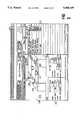
- FIG. 1is a schematic representation of a remote computer coupled to an instrument, the computer displaying the preferred embodiment of the graphical user interface for a remote diagnostic tool.
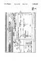
- FIG. 2depicts the graphical user interface depicted in FIG. 1 illustrating a top level view of an instrument schematic window, an instrument variables window and a memo pad window.
- FIG. 3depicts the graphical user interface as set forth in FIG. 2 in which the FID is highlighted in a box, as well as the corresponding FID instrument variables
- FIG. 4depicts the graphical user interface providing detailed FID information.
- FIG. 5depicts a graphical user interface as set forth in FIG. 1 upon actuation of the clipboard icon.
- FIG. 6depicts a more detailed version of the clipboard window set forth in FIG. 5.
- FIG. 7depicts a graphical user interface as set forth in FIG. 1 upon actuation of the lab notebook icon.
- FIG. 8depicts a graphical user interface as set forth in FIG. 1 upon actuation of the front panel icon.
- the inventionis a diagnostic tool which employs a graphical user interface with a plurality of interrelated windows for providing a graphical depiction of an instrument, instrument variables and their corresponding output values.
- the inventionprovides for continuous remote monitoring of the instrument and selected instrument variables to enhance remote instrument diagnosis and repair.
- FIG. 1depicts a computer 5 including a keyboard 6 and an input device 7 for moving a cursor 8 around the screen display 9.
- the computer 5having a Micrsoft Corporation Windows operating system, executes a software application program 11 written in the Visual Basic programming language to generate a graphical user interface 20 on the screen display 9 and to perform remote diagnostics and repair of the instrument 10.
- the computer employed in the preferred embodimentis commonly referred to as a PC, other types of personal computers and workstation running other forms of "Windows" based operating system or the like may be employed.
- An enter button 17 on the input device 7is employed for accessing information or data highlighted by the cursor. While the disclosed input device 7 is typically referred to as a mouse, trackballs and other known input devices may otherwise be employed.
- a first modem 12 and a second modem 14enable data transfer between the computer 5 and the instrument 10 over a standard telephone line 13.
- the diagnostic toolmonitors control signals generated by the instrument 10 to provide periodic updates of instrument operating values on the display 9.
- Sensors 18 within the instrument 10provide instrument configuration signals which are employed by the diagnostic tool for automatically displaying the current configuration of the instrument components and the connections between the components.
- the useris presented with a top level view on display 9 as illustrated in FIG. 2 in which the graphical user interface 220 comprises an instrument schematic window 230 depicting a top level view of the instrument, an instrument variables window 240 which identifies a corresponding level of instrument variables and associated instrument values, and a memo pad window 250 for tracking selected instrument variables.
- the graphical user interface 220comprises an instrument schematic window 230 depicting a top level view of the instrument, an instrument variables window 240 which identifies a corresponding level of instrument variables and associated instrument values, and a memo pad window 250 for tracking selected instrument variables.
- Instrument variables corresponding to individual components depicted on the instrument schematicmay be accessed in more detail by moving the cursor to highlight the component and depressing the enter button 17 on the input device 7 depicted in FIG. 1.
- a more detailed view of the highlighted componentmay be obtained by depressing the enter button 17 a second time which also updates the instrument variables window 240 with the corresponding instrument values at a level of detail represented by the detailed view.
- a cursor 208may be moved around the graphical depiction of the instrument 210 and its associated components (inlets 215, detectors 216, columns 217) through the use of an input device 7 (FIG. 1).
- the computer 5communicates to the instrument and requests the current instrument variables, setpoints and current values for that particular component such that they may be displayed on an instrument variables window 240.
- a memo pad window 250gives the user the ability to view and monitor selected instrument variables (like taking notes on a memo pad) even if they are not currently being displayed on the instrument schematic 230.
- Variablesmay be placed on the memo pad by moving the cursor to the variable name and depressing the enter button. The memo pad also allows the user to edit instrument variable setpoints.
- FIG. 3illustrates a more detailed view of the graphical user interface 220 depicted in FIG. 2, in which a graphical depiction of an FID 310 is highlighted within a box 312 by moving the cursor 308 over the FID 310 and depressing the enter button 17 on the input device 7 depicted in FIG. 1.
- Variables associated with the FID 310are illustrated in the instrument variables window 340.
- the memo pad window 350includes a number of instrument variables 355 (related to the NPD) that have been identified for display even though they are not currently being displayed on the instrument variables window 340.
- Depressing the enter button 17 on the input device 7 (FIG. 1) a second time while the cursor 308 (FIG. 3) is highlighting the FID 310causes the computer as illustrated in FIG. 4, to display a detailed schematic of the FID 410 in the instrument schematic window 430.
- the instrument variables window 440automatically updated with a detailed listing of the corresponding FID 310 instrument values (the computer 5 sends instructions to the instrument requesting that such information be provided).
- the name and value of an instrument component on the instrument variable display 440may be copied onto the memo pad window 450 by moving the cursor 408 to the desired instrument variable and depressing the enter button on the input device. Instrument values will be maintained on the memo pad 450 even if they are deleted from the instrument variables window 440.
- the usercan identify specific instrument variables for extended monitoring. In addition, notes, reminders or messages may be added to the memo pad 450.
- FIG. 5illustrates the graphical interface having a tool bar window 560 including a plurality of icons representing a plurality of instrument operations which may be accessed by the user to perform diagnostics.
- the iconsinclude a lab notebook icon 561, a log book icon 562, a front panel icon 563, a clipboard icon 564, and a question mark icon 565.
- Instrument operationsmay be accessed by moving the cursor 508 into position over a desired icon and depressing the enter button 17 on the input device 7 (FIG. 1).
- accessing the clipboard icon 564generates an icon window 570 illustrating the tests which are available for diagnosis of that portion of the instrument highlighted in the instrument schematic 530 (partially obscured by the icon window 570).
- the status bar icon 563may be employed for displaying the status of the diagnostic session (ie. modem connection status, connect time, general status messages and specific cursor location hints).
- Accessing the clipboard icon 564brings up a clipboard window 570 in the form of a test clipboard over the instrument schematic window 530 and instrument variables window 540.
- the clipboard window 570displays a top level view of a list of procedures and available procedure categories. Pressing the enter button 17 on the input device 7 (FIG. 1) a second time while the cursor is over a selected component in the instrument schematic will result in a listing of all the manual tests associated with the selected component. The user can select a test to run by moving the cursor 508 to the test name and depressing the enter button 17.
- FIG. 6depicts the graphical user interface 20 when the user accesses the test clipboard 670 after highlighting the FID (not shown) in the instrument schematic 630.
- the test clipboard 670may be employed for assisting the user in the process steps 680 required for testing the lighting of the FID flame and displays the results of the completed tests.
- the text on the clipboard 670changes dynamically as the user works through the steps of the test.
- the lab notebook icon 661represents the diagnostic history database.
- the diagnostic history databasestores diagnostic information.
- the diagnostics toolwill automatically store the instrument configuration, status and method information for every instrument connection. Values from both the instrument variable window 640 and the memo pad window 650 can be copied into the laboratory notebook, placing this information into the diagnostic history database, by moving the cursor to the desired instrument variable and depressing the enter button 17 on the input device 7.
- FIG. 7depicts the graphical user interface 20 when the lab notebook icon 761 is selected.
- a listing the instrument method setpoints 770is displayed. Since this is a read only display, the user cannot change variables on this form.
- FIG. 8depicts the graphical user interface 20 when the front panel icon 863 is accessed.
- a representation of the front panel of the instrumentis displayed, including an alphanumeric display which indicates the current method setpoints, as well as various status lights reflecting instrument status.
- the diagnostic tool provided by the inventionenhances remote diagnosis and repair of an instrument by graphically depicting the instrument, instrument variables and their corresponding values, all of which are continuously updated by providing a communication link between a computer executing a software application program and the instrument which makes available signals representing the instrument variables and values. While the invention has been described and illustrated with reference to specific embodiments in the area of gas chromatography, skilled in the art will recognize that modification and variations may be made such that the invention is equally applicable to the remote sensing of any type of instrument which has the ability to generate signals which can be communicated to a computer capable of executing the inventive diagnostic tool.
Landscapes
- Engineering & Computer Science (AREA)
- Physics & Mathematics (AREA)
- General Physics & Mathematics (AREA)
- Automation & Control Theory (AREA)
- Human Computer Interaction (AREA)
- Digital Computer Display Output (AREA)
Abstract
Description
Claims (19)
Priority Applications (1)
| Application Number | Priority Date | Filing Date | Title |
|---|---|---|---|
| US08/376,720US5588109A (en) | 1995-01-23 | 1995-01-23 | User interface for a remote diagnostic device |
Applications Claiming Priority (1)
| Application Number | Priority Date | Filing Date | Title |
|---|---|---|---|
| US08/376,720US5588109A (en) | 1995-01-23 | 1995-01-23 | User interface for a remote diagnostic device |
Publications (1)
| Publication Number | Publication Date |
|---|---|
| US5588109Atrue US5588109A (en) | 1996-12-24 |
Family
ID=23486192
Family Applications (1)
| Application Number | Title | Priority Date | Filing Date |
|---|---|---|---|
| US08/376,720Expired - Fee RelatedUS5588109A (en) | 1995-01-23 | 1995-01-23 | User interface for a remote diagnostic device |
Country Status (1)
| Country | Link |
|---|---|
| US (1) | US5588109A (en) |
Cited By (36)
| Publication number | Priority date | Publication date | Assignee | Title |
|---|---|---|---|---|
| WO1999009532A3 (en)* | 1997-08-19 | 1999-05-06 | Siemens Ag | Method for improved operability in control systems |
| WO1999046649A1 (en)* | 1998-03-09 | 1999-09-16 | Siemens Aktiengesellschaft | Method and device for processing the data of a technical installation which is stored in different data memories in a user-oriented manner |
| WO2000063754A1 (en)* | 1999-04-21 | 2000-10-26 | Ivar Kvale | Structure management and control system |
| WO2000049475A3 (en)* | 1999-02-17 | 2000-12-21 | Westinghouse Savannah River Co | Systems and methods for interactive virtual reality process control, simulation, and training (ivrpcst) |
| US6205547B1 (en)* | 1998-11-20 | 2001-03-20 | Intel Corporation | Computer system management apparatus and method |
| WO2001002891A3 (en)* | 1999-07-02 | 2001-03-29 | Siemens Ag | Method for monitoring or installing new program codes in an industrial installation |
| US6310630B1 (en) | 1997-12-12 | 2001-10-30 | International Business Machines Corporation | Data processing system and method for internet browser history generation |
| EP1037128A3 (en)* | 1999-03-08 | 2001-11-14 | Siemens Aktiengesellschaft | System and method for conducting and monitoring a process of a technical installation |
| US6327579B1 (en)* | 1993-11-04 | 2001-12-04 | Christopher M. Crawford | Online computer services including help desk, anti-virus and/or application service features |
| WO2001069330A3 (en)* | 2000-03-10 | 2002-03-28 | Meta Controls Inc | Distributed machine control software architecture |
| US6370586B2 (en) | 1998-10-30 | 2002-04-09 | Intel Corporation | Monitoring of an electronic device with a system management controller |
| US20020051216A1 (en)* | 2000-03-10 | 2002-05-02 | Meta Controls, Inc. | Smart camera |
| WO2002017026A3 (en)* | 2000-08-22 | 2002-06-06 | Siemens Ag | Context-dependent protocol creation system and method, especially for use in the field of production, assembly, service or maintenance |
| US20020091309A1 (en)* | 2000-11-17 | 2002-07-11 | Auer John E. | System and method for processing patient information |
| US20020116246A1 (en)* | 2001-01-17 | 2002-08-22 | Claas Selbstfahrende Erntemaschinen Gmbh | Method for planning a repair of mobile machines |
| WO2002067064A2 (en) | 2001-02-21 | 2002-08-29 | Koenig & Bauer Aktiengesellschaft | Method and device for carrying out the functional check and functional checking of a technical unit |
| US6463359B2 (en) | 2001-02-20 | 2002-10-08 | Infotech Ag | Micro-alignment pick-up head |
| US6557251B2 (en) | 2000-03-10 | 2003-05-06 | Infotech, A.G. | Digital feature separation |
| US6581054B1 (en) | 1999-07-30 | 2003-06-17 | Computer Associates Think, Inc. | Dynamic query model and method |
| US6605500B2 (en) | 2000-03-10 | 2003-08-12 | Infotech Ag | Assembly process |
| US6842758B1 (en) | 1999-07-30 | 2005-01-11 | Computer Associates Think, Inc. | Modular method and system for performing database queries |
| US20050090907A1 (en)* | 2000-03-10 | 2005-04-28 | Adept Technology, Inc | Smart camera |
| US20060147203A1 (en)* | 2004-12-30 | 2006-07-06 | Thinguldstad Arthur M | Optical network element with remote access capability |
| US7080051B1 (en)* | 1993-11-04 | 2006-07-18 | Crawford Christopher M | Internet download systems and methods providing software to internet computer users for local execution |
| US20060212919A1 (en)* | 2000-10-11 | 2006-09-21 | Tsang Gilbert H Y | IP address discovery for cable modem in Set-Top Box |
| KR100710758B1 (en) | 2005-04-18 | 2007-04-24 | 삼성전자주식회사 | Installation system for software and method thereof and storage material |
| US20080169044A1 (en)* | 2006-10-20 | 2008-07-17 | Forhealth Technologies, Inc. | Automated drug preparation apparatus including syringe loading, preparation and filling |
| US7644366B1 (en)* | 1999-07-30 | 2010-01-05 | Computer Associates Think, Inc. | Method and system for displaying a plurality of discrete files in a compound file |
| US20100241901A1 (en)* | 2009-02-12 | 2010-09-23 | Roland Jahn | Method and apparatus for checking a control program in an industrial system |
| US20110009984A1 (en)* | 2009-07-09 | 2011-01-13 | Mukhi Sultan Q | Presenting dynamic scada data |
| US20110153039A1 (en)* | 2009-12-23 | 2011-06-23 | Viktor Gvelesiani | System and method for providing diagnostic information and graphical user interface therefor |
| WO2013053975A1 (en)* | 2011-10-11 | 2013-04-18 | Sandvik Mining And Construction Oy | Maintenance of work machines |
| US20130132897A1 (en)* | 2011-11-14 | 2013-05-23 | Bio-Rad Laboratories, Inc. | Chromatography configuration interface |
| US20130218352A1 (en)* | 2011-08-24 | 2013-08-22 | Bio-Rad Laboratories, Inc. | Modular automated chromatography system |
| US20140282168A1 (en)* | 2013-03-12 | 2014-09-18 | Air Liquide Electronics Us Lp | Data sampling method for determining salient values in a large data stream |
| US20140328471A1 (en)* | 2003-05-12 | 2014-11-06 | Aware, Inc. | Telecommunication diagnostic information management |
Citations (9)
| Publication number | Priority date | Publication date | Assignee | Title |
|---|---|---|---|---|
| US4434489A (en)* | 1980-10-13 | 1984-02-28 | Marconi Instruments Limited | Automatic test systems |
| US5023817A (en)* | 1989-03-06 | 1991-06-11 | Xerox Corporation | Jam history and diagnostics |
| US5124908A (en)* | 1990-04-23 | 1992-06-23 | Ellis Corporation | User interactive expert machine controller |
| US5224055A (en)* | 1989-02-10 | 1993-06-29 | Plessey Semiconductors Limited | Machine for circuit design |
| US5245324A (en)* | 1990-09-24 | 1993-09-14 | Snap-On Tools Corporation | Digital engine analyzer |
| US5375199A (en)* | 1991-06-04 | 1994-12-20 | Digital Equipment Corporation | System monitoring method and device including a graphical user interface to view and manipulate system information |
| US5420977A (en)* | 1990-10-24 | 1995-05-30 | Vanderbilt University | Multiple aspect operator interface for displaying fault diagnostics results in intelligent process control systems |
| US5504863A (en)* | 1994-02-07 | 1996-04-02 | Fujitsu Limited | Centralized network monitoring device for monitoring devices via intermediate monitoring devices by means of polling and including display means displaying screens corresponding to heirarchic levels of the monitored devices in a network |
| US5517607A (en)* | 1991-09-30 | 1996-05-14 | Fujitsu Limited | Graphic processing apparatus utilizing a CAD system |
- 1995
- 1995-01-23USUS08/376,720patent/US5588109A/ennot_activeExpired - Fee Related
Patent Citations (9)
| Publication number | Priority date | Publication date | Assignee | Title |
|---|---|---|---|---|
| US4434489A (en)* | 1980-10-13 | 1984-02-28 | Marconi Instruments Limited | Automatic test systems |
| US5224055A (en)* | 1989-02-10 | 1993-06-29 | Plessey Semiconductors Limited | Machine for circuit design |
| US5023817A (en)* | 1989-03-06 | 1991-06-11 | Xerox Corporation | Jam history and diagnostics |
| US5124908A (en)* | 1990-04-23 | 1992-06-23 | Ellis Corporation | User interactive expert machine controller |
| US5245324A (en)* | 1990-09-24 | 1993-09-14 | Snap-On Tools Corporation | Digital engine analyzer |
| US5420977A (en)* | 1990-10-24 | 1995-05-30 | Vanderbilt University | Multiple aspect operator interface for displaying fault diagnostics results in intelligent process control systems |
| US5375199A (en)* | 1991-06-04 | 1994-12-20 | Digital Equipment Corporation | System monitoring method and device including a graphical user interface to view and manipulate system information |
| US5517607A (en)* | 1991-09-30 | 1996-05-14 | Fujitsu Limited | Graphic processing apparatus utilizing a CAD system |
| US5504863A (en)* | 1994-02-07 | 1996-04-02 | Fujitsu Limited | Centralized network monitoring device for monitoring devices via intermediate monitoring devices by means of polling and including display means displaying screens corresponding to heirarchic levels of the monitored devices in a network |
Non-Patent Citations (2)
| Title |
|---|
| Knapp, P., "Digital Maintenance Information (DMI) system," Autotestcon '89, pp. 138-145. |
| Knapp, P., Digital Maintenance Information (DMI) system, Autotestcon 89, pp. 138 145.* |
Cited By (61)
| Publication number | Priority date | Publication date | Assignee | Title |
|---|---|---|---|---|
| US7080051B1 (en)* | 1993-11-04 | 2006-07-18 | Crawford Christopher M | Internet download systems and methods providing software to internet computer users for local execution |
| US6411943B1 (en)* | 1993-11-04 | 2002-06-25 | Christopher M. Crawford | Internet online backup system provides remote storage for customers using IDs and passwords which were interactively established when signing up for backup services |
| US6327579B1 (en)* | 1993-11-04 | 2001-12-04 | Christopher M. Crawford | Online computer services including help desk, anti-virus and/or application service features |
| WO1999009532A3 (en)* | 1997-08-19 | 1999-05-06 | Siemens Ag | Method for improved operability in control systems |
| RU2233484C2 (en)* | 1997-08-19 | 2004-07-27 | Сименс Акциенгезелльшафт | Method for enhancing dispatch control system maintenance |
| US6310630B1 (en) | 1997-12-12 | 2001-10-30 | International Business Machines Corporation | Data processing system and method for internet browser history generation |
| WO1999046649A1 (en)* | 1998-03-09 | 1999-09-16 | Siemens Aktiengesellschaft | Method and device for processing the data of a technical installation which is stored in different data memories in a user-oriented manner |
| US6798428B1 (en) | 1998-03-09 | 2004-09-28 | Framatome Anp Gmbh | Method and apparatus for processing data of a technical installation stored in a user-specific manner in different data memories |
| US6370586B2 (en) | 1998-10-30 | 2002-04-09 | Intel Corporation | Monitoring of an electronic device with a system management controller |
| US6205547B1 (en)* | 1998-11-20 | 2001-03-20 | Intel Corporation | Computer system management apparatus and method |
| WO2000049475A3 (en)* | 1999-02-17 | 2000-12-21 | Westinghouse Savannah River Co | Systems and methods for interactive virtual reality process control, simulation, and training (ivrpcst) |
| EP1037128A3 (en)* | 1999-03-08 | 2001-11-14 | Siemens Aktiengesellschaft | System and method for conducting and monitoring a process of a technical installation |
| WO2000063754A1 (en)* | 1999-04-21 | 2000-10-26 | Ivar Kvale | Structure management and control system |
| WO2001002891A3 (en)* | 1999-07-02 | 2001-03-29 | Siemens Ag | Method for monitoring or installing new program codes in an industrial installation |
| US7318227B1 (en) | 1999-07-02 | 2008-01-08 | Siemens Aktiengesellschaft | Method for monitoring or installing new program codes in an industrial installation |
| US6581054B1 (en) | 1999-07-30 | 2003-06-17 | Computer Associates Think, Inc. | Dynamic query model and method |
| US8091040B2 (en) | 1999-07-30 | 2012-01-03 | Computer Associates Think, Inc. | Method and system for displaying a plurality of discrete files in a compound file |
| US7644366B1 (en)* | 1999-07-30 | 2010-01-05 | Computer Associates Think, Inc. | Method and system for displaying a plurality of discrete files in a compound file |
| US20100153874A1 (en)* | 1999-07-30 | 2010-06-17 | Computer Associates Think, Inc. | Method and system for displaying a plurality of discrete files in a compound file |
| US6842758B1 (en) | 1999-07-30 | 2005-01-11 | Computer Associates Think, Inc. | Modular method and system for performing database queries |
| US20020051216A1 (en)* | 2000-03-10 | 2002-05-02 | Meta Controls, Inc. | Smart camera |
| US6734537B1 (en) | 2000-03-10 | 2004-05-11 | Infotech, Ag | Assembly process |
| US6605500B2 (en) | 2000-03-10 | 2003-08-12 | Infotech Ag | Assembly process |
| US6557251B2 (en) | 2000-03-10 | 2003-05-06 | Infotech, A.G. | Digital feature separation |
| US20050090907A1 (en)* | 2000-03-10 | 2005-04-28 | Adept Technology, Inc | Smart camera |
| US6985780B2 (en) | 2000-03-10 | 2006-01-10 | Adept Technology, Inc. | Smart camera |
| US6988008B2 (en) | 2000-03-10 | 2006-01-17 | Adept Technology, Inc. | Smart camera |
| WO2001069330A3 (en)* | 2000-03-10 | 2002-03-28 | Meta Controls Inc | Distributed machine control software architecture |
| WO2002017026A3 (en)* | 2000-08-22 | 2002-06-06 | Siemens Ag | Context-dependent protocol creation system and method, especially for use in the field of production, assembly, service or maintenance |
| US20060212919A1 (en)* | 2000-10-11 | 2006-09-21 | Tsang Gilbert H Y | IP address discovery for cable modem in Set-Top Box |
| US7546628B2 (en)* | 2000-10-11 | 2009-06-09 | Sony Corporation | IP address discovery for cable modem in set-top box |
| US20020091309A1 (en)* | 2000-11-17 | 2002-07-11 | Auer John E. | System and method for processing patient information |
| US7590551B2 (en) | 2000-11-17 | 2009-09-15 | Draeger Medical Systems, Inc. | System and method for processing patient information |
| US20020116246A1 (en)* | 2001-01-17 | 2002-08-22 | Claas Selbstfahrende Erntemaschinen Gmbh | Method for planning a repair of mobile machines |
| US6463359B2 (en) | 2001-02-20 | 2002-10-08 | Infotech Ag | Micro-alignment pick-up head |
| US7058536B2 (en) | 2001-02-21 | 2006-06-06 | Koenig & Bauer Aktiengesellschaft | Method and device for performing a functionality test of a technical device |
| US20050210385A1 (en)* | 2001-02-21 | 2005-09-22 | Gabriel Gunther E | Method and Device for Carrying Out the Functional Check and Functional Checking of a Technical Unit |
| WO2002067064A3 (en)* | 2001-02-21 | 2003-01-09 | Koenig & Bauer Ag | Method and device for carrying out the functional check and functional checking of a technical unit |
| WO2002067064A2 (en) | 2001-02-21 | 2002-08-29 | Koenig & Bauer Aktiengesellschaft | Method and device for carrying out the functional check and functional checking of a technical unit |
| US9215312B2 (en)* | 2003-05-12 | 2015-12-15 | Broadcom Corporation | Telecommunication diagnostic information management |
| US20140328471A1 (en)* | 2003-05-12 | 2014-11-06 | Aware, Inc. | Telecommunication diagnostic information management |
| US20060147203A1 (en)* | 2004-12-30 | 2006-07-06 | Thinguldstad Arthur M | Optical network element with remote access capability |
| KR100710758B1 (en) | 2005-04-18 | 2007-04-24 | 삼성전자주식회사 | Installation system for software and method thereof and storage material |
| US20080169044A1 (en)* | 2006-10-20 | 2008-07-17 | Forhealth Technologies, Inc. | Automated drug preparation apparatus including syringe loading, preparation and filling |
| US20100241901A1 (en)* | 2009-02-12 | 2010-09-23 | Roland Jahn | Method and apparatus for checking a control program in an industrial system |
| US20110009984A1 (en)* | 2009-07-09 | 2011-01-13 | Mukhi Sultan Q | Presenting dynamic scada data |
| US8255186B2 (en)* | 2009-07-09 | 2012-08-28 | Air Liquide Large Industries U.S. Lp | Presenting dynamic SCADA data |
| US20110153039A1 (en)* | 2009-12-23 | 2011-06-23 | Viktor Gvelesiani | System and method for providing diagnostic information and graphical user interface therefor |
| US20130218352A1 (en)* | 2011-08-24 | 2013-08-22 | Bio-Rad Laboratories, Inc. | Modular automated chromatography system |
| US9304518B2 (en)* | 2011-08-24 | 2016-04-05 | Bio-Rad Laboratories, Inc. | Modular automated chromatography system |
| US10082489B2 (en) | 2011-08-24 | 2018-09-25 | Bio-Rad Laboratories, Inc. | Modular automated chromatography system |
| US10401335B2 (en) | 2011-08-24 | 2019-09-03 | Bio-Rad Laboratories, Inc. | Modular automated chromatography system |
| US10444204B2 (en) | 2011-08-24 | 2019-10-15 | Bio-Rad Laboratories, Inc. | Modular automated chromatography system |
| US10900938B2 (en) | 2011-08-24 | 2021-01-26 | Bio-Rad Laboratories, Inc. | Modular automated chromatography system |
| AU2011379005B2 (en)* | 2011-10-11 | 2015-10-08 | Sandvik Mining And Construction Oy | Maintenance of work machines |
| WO2013053975A1 (en)* | 2011-10-11 | 2013-04-18 | Sandvik Mining And Construction Oy | Maintenance of work machines |
| US20130132897A1 (en)* | 2011-11-14 | 2013-05-23 | Bio-Rad Laboratories, Inc. | Chromatography configuration interface |
| US9182886B2 (en)* | 2011-11-14 | 2015-11-10 | Bio-Rad Laboratories Inc. | Chromatography configuration interface |
| US10489036B2 (en) | 2011-11-14 | 2019-11-26 | Bio-Rad Laboratories, Inc. | Chromatography configuration interface |
| US20140282168A1 (en)* | 2013-03-12 | 2014-09-18 | Air Liquide Electronics Us Lp | Data sampling method for determining salient values in a large data stream |
| US9372603B2 (en)* | 2013-03-12 | 2016-06-21 | Air Liquide Large Industries U.S. Lp | Data sampling method for determining salient values in a large data stream |
Similar Documents
| Publication | Publication Date | Title |
|---|---|---|
| US5588109A (en) | User interface for a remote diagnostic device | |
| US6240420B1 (en) | Customer support search engine system and method of searching data using the search engine system | |
| US5594663A (en) | Remote diagnostic tool | |
| US7076713B1 (en) | Test generator for converting a model of computer component object behavior and stimulus values to test script | |
| US6201996B1 (en) | Object-oriented programmable industrial controller with distributed interface architecture | |
| US5774887A (en) | Customer service electronic form generating system | |
| US6356859B1 (en) | Process monitoring system | |
| US5377318A (en) | Line probe diagnostic display in an iconic programming system | |
| US4821211A (en) | Method of navigating among program menus using a graphical menu tree | |
| US5450539A (en) | Apparatus and method of dynamically displaying a graphic button on a monitor | |
| US8015542B1 (en) | System and method for creating a graphical program which invokes methods and properties of objects | |
| US7200817B2 (en) | Graphical program execution on a personal digital assistant | |
| US7062718B2 (en) | Configuration diagram which graphically displays program relationship | |
| US4654852A (en) | On-line problem-determination procedure for diagnosis of faults in a data-processing system | |
| US5325481A (en) | Method for creating dynamic user panels in an iconic programming system | |
| US8881105B2 (en) | Test case manager | |
| US7594220B2 (en) | Configuration diagram with context sensitive connectivity | |
| RU2439688C2 (en) | Identification of design issues in electronic forms | |
| US6701285B2 (en) | Method and apparatus for monitoring the operation of an industrial process | |
| US20110072338A1 (en) | Dynamic Hyperlinks for Process Control Systems | |
| US20030037322A1 (en) | Graphically configuring program invocation relationships by creating or modifying links among program icons in a configuration diagram | |
| US20020174264A1 (en) | System and method for obtaining driver software and documentation for a detected hardware and software configuration | |
| GB2495024A (en) | Dynamic user interface for configuring and managing a process control system | |
| JPH05241797A (en) | Method for systemizing software application package generating work | |
| CN113076717B (en) | Data automatic association method, device and electronic equipment |
Legal Events
| Date | Code | Title | Description |
|---|---|---|---|
| AS | Assignment | Owner name:HEWLETT-PACKARD COMPANY, CALIFORNIA Free format text:ASSIGNMENT OF ASSIGNORS INTEREST;ASSIGNORS:DICKINSON, IAN J.;EICHBERGER, HORST;MESSAROS, DAVID W.;AND OTHERS;REEL/FRAME:007397/0005;SIGNING DATES FROM 19950209 TO 19950222 | |
| FEPP | Fee payment procedure | Free format text:PAYOR NUMBER ASSIGNED (ORIGINAL EVENT CODE: ASPN); ENTITY STATUS OF PATENT OWNER: LARGE ENTITY | |
| AS | Assignment | Owner name:HEWLETT-PACKARD COMPANY, A DELAWARE CORPORATION, C Free format text:MERGER;ASSIGNOR:HEWLETT-PACKARD COMPANY, A CALIFORNIA CORPORATION;REEL/FRAME:010841/0649 Effective date:19980520 | |
| AS | Assignment | Owner name:AGILENT TECHNOLOGIES INC, CALIFORNIA Free format text:ASSIGNMENT OF ASSIGNORS INTEREST;ASSIGNOR:HEWLETT-PACKARD COMPANY;REEL/FRAME:010977/0540 Effective date:19991101 | |
| FPAY | Fee payment | Year of fee payment:4 | |
| FPAY | Fee payment | Year of fee payment:8 | |
| REMI | Maintenance fee reminder mailed | ||
| LAPS | Lapse for failure to pay maintenance fees | ||
| STCH | Information on status: patent discontinuation | Free format text:PATENT EXPIRED DUE TO NONPAYMENT OF MAINTENANCE FEES UNDER 37 CFR 1.362 | |
| FP | Lapsed due to failure to pay maintenance fee | Effective date:20081224 |