US5587747A - Interchangeable eyeglass lens system - Google Patents
Interchangeable eyeglass lens systemDownload PDFInfo
- Publication number
- US5587747A US5587747AUS08/482,291US48229195AUS5587747AUS 5587747 AUS5587747 AUS 5587747AUS 48229195 AUS48229195 AUS 48229195AUS 5587747 AUS5587747 AUS 5587747A
- Authority
- US
- United States
- Prior art keywords
- lens
- nosebridge
- frame
- lenses
- stud
- Prior art date
- Legal status (The legal status is an assumption and is not a legal conclusion. Google has not performed a legal analysis and makes no representation as to the accuracy of the status listed.)
- Expired - Lifetime
Links
- 238000000034methodMethods0.000claimsabstractdescription9
- 230000007246mechanismEffects0.000claimsdescription13
- 238000007373indentationMethods0.000description9
- 239000003086colorantSubstances0.000description5
- 230000000694effectsEffects0.000description5
- 239000000463materialSubstances0.000description4
- 230000008569processEffects0.000description3
- 230000003466anti-cipated effectEffects0.000description2
- 230000008859changeEffects0.000description2
- 238000012986modificationMethods0.000description2
- 230000004048modificationEffects0.000description2
- 230000002093peripheral effectEffects0.000description2
- 230000002459sustained effectEffects0.000description2
- QTBSBXVTEAMEQO-UHFFFAOYSA-MAcetateChemical compoundCC([O-])=OQTBSBXVTEAMEQO-UHFFFAOYSA-M0.000description1
- 229910001316Ag alloyInorganic materials0.000description1
- 229910000990Ni alloyInorganic materials0.000description1
- 239000004677NylonSubstances0.000description1
- XBDQKXXYIPTUBI-UHFFFAOYSA-MPropionateChemical compoundCCC([O-])=OXBDQKXXYIPTUBI-UHFFFAOYSA-M0.000description1
- 241000220317RosaSpecies0.000description1
- 230000006978adaptationEffects0.000description1
- 230000008901benefitEffects0.000description1
- 230000002153concerted effectEffects0.000description1
- 238000010276constructionMethods0.000description1
- 230000005484gravityEffects0.000description1
- 238000003780insertionMethods0.000description1
- 230000014759maintenance of locationEffects0.000description1
- 230000013011matingEffects0.000description1
- 238000000465mouldingMethods0.000description1
- 229920001778nylonPolymers0.000description1
- 229920002647polyamidePolymers0.000description1
- 239000004417polycarbonateSubstances0.000description1
- 229920000515polycarbonatePolymers0.000description1
- 239000002861polymer materialSubstances0.000description1
- 230000002265preventionEffects0.000description1
- 239000012858resilient materialSubstances0.000description1
- 238000007493shaping processMethods0.000description1
- 239000004332silverSubstances0.000description1
- 241000894007speciesSpecies0.000description1
- 239000010935stainless steelSubstances0.000description1
- 229910001220stainless steelInorganic materials0.000description1
- 230000003245working effectEffects0.000description1
Images


Classifications
- G—PHYSICS
- G02—OPTICS
- G02C—SPECTACLES; SUNGLASSES OR GOGGLES INSOFAR AS THEY HAVE THE SAME FEATURES AS SPECTACLES; CONTACT LENSES
- G02C1/00—Assemblies of lenses with bridges or browbars
- G02C1/04—Bridge or browbar secured to or integral with partial rims, e.g. with partially-flexible rim for holding lens
- G—PHYSICS
- G02—OPTICS
- G02C—SPECTACLES; SUNGLASSES OR GOGGLES INSOFAR AS THEY HAVE THE SAME FEATURES AS SPECTACLES; CONTACT LENSES
- G02C1/00—Assemblies of lenses with bridges or browbars
- G02C1/02—Bridge or browbar secured to lenses without the use of rims
- G—PHYSICS
- G02—OPTICS
- G02C—SPECTACLES; SUNGLASSES OR GOGGLES INSOFAR AS THEY HAVE THE SAME FEATURES AS SPECTACLES; CONTACT LENSES
- G02C5/00—Constructions of non-optical parts
- G02C5/02—Bridges; Browbars; Intermediate bars
- G—PHYSICS
- G02—OPTICS
- G02C—SPECTACLES; SUNGLASSES OR GOGGLES INSOFAR AS THEY HAVE THE SAME FEATURES AS SPECTACLES; CONTACT LENSES
- G02C5/00—Constructions of non-optical parts
- G02C5/02—Bridges; Browbars; Intermediate bars
- G02C5/06—Bridges; Browbars; Intermediate bars with resilient means
- G—PHYSICS
- G02—OPTICS
- G02C—SPECTACLES; SUNGLASSES OR GOGGLES INSOFAR AS THEY HAVE THE SAME FEATURES AS SPECTACLES; CONTACT LENSES
- G02C2200/00—Generic mechanical aspects applicable to one or more of the groups G02C1/00 - G02C5/00 and G02C9/00 - G02C13/00 and their subgroups
- G02C2200/04—Junctions between frame elements having a click function
- G—PHYSICS
- G02—OPTICS
- G02C—SPECTACLES; SUNGLASSES OR GOGGLES INSOFAR AS THEY HAVE THE SAME FEATURES AS SPECTACLES; CONTACT LENSES
- G02C2200/00—Generic mechanical aspects applicable to one or more of the groups G02C1/00 - G02C5/00 and G02C9/00 - G02C13/00 and their subgroups
- G02C2200/26—Coil spring pushed upon actuation
Definitions
- the inventionrelates to spectacles and other eyewear such as sunglasses; more particularly, it relates to a system for readily interchangeable lenses on an eyeglass or sunglass frame.
- sunglass lensesbreak or get scratched, or different activities suggest or require different shapes and/or colors of lenses. For instance, in bright sunlight, a darker shade may be indicated, while in overcast light, a yellow or rose tint can brighten the view; bicycle athletes want a lens with substantial wrap depth to protect their eyes and to improve aerodynamics, but for running or apres-cycle they may want a different shape or color. Sometimes the dictates of fashion simply require a different color or shape lens set.
- Clip-on lensesare attached to a pair of eyeglasses by a clip, typically located at the center of the clip-on lenses.
- the clipattaches over the nosepiece of the eyeglasses.
- the clipsnaps over the sides of each of a pair of separate lenses formed to the shape of specific eyeglasses for which they are provided.
- a tinted lensis snapped into a circumferential groove inboard of the clear lens.
- clear prescription lensesare hung, hinged or otherwise detachably mounted inboard of a pair of conventional sunglass lenses.
- some additional structureis added to the sunglass frames for holding a prescription lens or pair of lenses behind the sunglass lenses; however in one species, the frames themselves are modified with threads to receive a "screwed-in" prescription lens for each lens of the sunglasses.
- Clip-on lensescan be disadvantageous, however, because they result in less than desirable optics, typically through an inability to control the spacing and angular relationship between the sunglass lens and its clear lens with any precision or degree of stability, and because they are cosmetically unattractive.
- Another object of the inventionis to provide relatively resilient tangs or studs adapted for use in such a replaceable lens system to provide quick, easy, reliable and secure engagement and release of the replaceable lenses.
- the inventionaddresses the above needs and provides such a system.
- the inventionis an interchangeable eyeglass lens system for sunglasses and other eyewear so that more than one pair of lenses can be used practically with a particular frame.
- Lenses particularly adapted for interchangeability and having concavities on the lens periphery for engaging fastener devices, such as studs and spring loaded detents on the frame,are included in the system.
- a complete systemwould have a pair of removable lenses, a frame having a nosebridge which can be removable also, and fasteners mounted on or within the frame or nosebridge for releasably holding the lenses in place on the frame by interengaging the concavities on the lenses.
- a removable nosebridge with an antirotational device, and a spring loaded detent mechanism adapted for use in providing quick and easy removal of the lenses and sure, stable retention of the lenses while in placeare optionally also part of the system, as is a method of removably attaching a lens to the system's frame,
- the interchangeable eyeglass lens of the systemhas two or more concavities, such as notches, nooks, recesses, hollows or indentations, disposed along the lens periphery at some distance to each other, typically along an upper peripheral edge of the lens at substantially opposing ends of upper edge.
- the general purpose of the concavitiesis to provide the female part of a male/female releasable attachment system at two or more points along each lens (although in some embodiments, a single screw through an aperture in the lens may suffice).
- the two concavitiesare generally keyhole shaped (or in other words, a substantially circular recess connected to the periphery by a slot that is narrower than the recess).
- the concavitiesare semicircular shaped notches in the lens periphery positioned more or less at the upper corners of the lens.
- Such upper corner positioningis generally preferred so that a simple "brow bar" type of frame can be used, with all lens attachment occurring on the brow bar and the upper edge of the lens.
- Other attachment locations on differently shaped frame setswill suffice however.
- a basic version of the interchangeable eyeglass lens systemhas at least one interchangeable lens, a frame, and at least one and preferably two lens fastener devices (the male portion of the fastener device in particular) mounted on the frame for each lens.
- a generally preferred fasteneris a generally rivet shaped stud having a head portion and a shaft or post portion for releasably engaging a generally correspondingly shaped recess or notch on the lens periphery.
- Another generally preferred fasteneris a relatively resilient tang or stud made integral to or provided by the frame for releasably engaging a generally correspondingly shaped recess or notch on the lens periphery by initially deflecting before the lens during the lens-mounting process, then returning to its original position and configuration within the notch or recess as the lens moves into its proper place, in order to secure the lens in the proper mounted position.
- the lens notchis typically substantially circular to suit the preferred cross section of the stud post.
- a generally preferred pair of fastenerswill be a pair of studs and a pair of notches in the lens periphery located substantially at opposite upper corners of said lens, with the stud positions on the frame corresponding to the notch spacing, or a pair of similarly situated, relatively resilient tangs or studs and correspondent peripheral lens notches.
- a generally preferred frameis a relatively simple brow bar and nosebridge, with the nosebridge being optionally removable.
- the nosebridgepreferably has a pair of lens receiving channels to support the respective inner lens edges.
- there is one tab in each of the lens channelsfor releasably interengaging a correspondingly shaped notch in an inner edge of each lens.
- the brow barhas a stud disposed near each hinge end or temple end of the brow bar, and the nosebridge has mounted inside it a spring loaded detent mechanism or a relatively resilient tang or stud made integral to or provided on the nosebridge for releasably interengaging a notch in the upper inner corner of each lens.
- the preferred lens for use with this spring loaded detent nosebridgehas a downwardly sloping nook (forming a kind of "hook" shape at an upper outer corner of the lens) for pivotally and releasably interengaging the outer stud.
- the sliding pin detent mechanismhas a pair of pins at either end of a spring, with the pins and spring laying in a channel formed in a portion of the nosebridge to from a spring and pin housing.
- the housinghas a pair of collars and each pin has a shoulder with a generally matching shape, so the collars restrain the pins from being pushed out of the channel too far by the spring.
- the pinshave generally smoothly radiused ends opposite the spring to facilitate smooth entry and exit from the corresponding lens notches along the ramped portions of the notch, as will be appreciated by those skilled in the art.
- the "pins"can be spherical in shape or substantially so as in conventional detent ball mechanisms.
- the complete pin/spring housingis formed in part by a removable nosebridge and in part by the brow bar, and a channel as described above in one or the other, but preferably in the nosebridge.
- Preferred pinshave a generally elongate shape and, while rounded in cross section at sides and bottom to facilitate smooth sliding in the channel and over the collars which have matching cross sections, at least one face is substantially flat to promote smooth sliding engagement with the mating surface of the brow bar at its interface with the nosebridge.
- the relatively resilient tang or studis made integral to or provided on the removeable nosebridge, and is made of any material sufficiently flexible and resilient to releasably engage a generally correspondingly shaped recess or notch on the periphery of a lens.
- the tang or studinitially deflects before the lens during the lens-insertion process, then returns to its original position and configuration within the notch or recess as the lens is moved into its proper place.
- the tang or studis sufficiently resilient to hold the lens in position while the eyeglass set is worn.
- One removable nosebridge embodimenthas a pair of flanges for supporting inner edges of a pair of lenses, and a pair of lens stays or tabs for defining in part with the pair of flanges, a pair of lens receiving channels.
- a generally preferred nosebridgealso has at least one antirotation device so that the nosebridge resists rocking and other shifting motion relative to the frame even when the lenses are removed from the frame.
- the antirotational devicecan be a keyway in the nosebridge for receiving a correspondingly shaped key on the brow bar, or it can be a recess in the nosebridge for receiving a correspondingly shaped boss on the brow bar, or both.
- Alternate antirotational structuresmay also by applied such as a variation on conventional tongue and groove structure.
- the inventionalso includes a method of interchanging a lens in an eyeglass frame having a nosebridge with the following steps: removably attaching the lens by aligning a downwardly sloping nook at an upper outer corner of the lens with a stud mounted on a brow bar of the frame at an outer end of the frame, so that the inner edge of the lens is below the nosebridge, and sliding the lens under a head on the stud along the nook; pivoting the lens upwardly around the stud/nook engagement and into a lens receiving channel on the nosebridge; continuing to pivot said lens upwardly along the channel until a notch at an upper inner corner of the lens snaps into engagement with a spring loaded detent or a relatively resilient stud or tang provided in the nosebridge; removing the lens by pressing downward firmly and gently at an upper inner corner of the lens to disengage the tang or detent and slide the lens downwardly through the channel until an upper edge of the lens is below the nosebridge; sliding the lens from under the head on the stud along the nook until the lens
- the inventionis both a method and apparatus for detachable eyeglass lenses, such as for instance in sunglasses, whereby a preferably relatively rigid, expensive frame member and nosebridge assembly can be removably but reliably and securely fitted with a variety of colors, shades, curvatures, or prescriptions of lenses without compromising the structural integrity of the overall eyeglass set. Scratched or otherwise damaged or worn out lenses can thereby be replaced at relatively low cost, and without having to buy new or different sunglasses.
- lensesare fashioned, such as by molding, to have two indentations on either side of an upper edge of each lens piece. These indentations mate with and preferably snap into two detent means (such as posts, tangs, or pins) spaced appropriately on the frame. The lenses remain securely mounted on the frame until snapped off.
- each lensmay be removably attached to the frame with a screw passing through an upper centrally located hole in the lens.
- the lens indentationsare in some embodiments specially adapted for snap attachment by shaping the indentation to have a relatively restricted opening, as compared to the size of the indentation required to accommodate the holding pin or post.
- the inner mount (that is, "pin", tang, or detent) for each lensis integral to a detachable nosebridge piece, rather than mounted directly on the frame itself, so that one detent is on the brow bar portion of the frame at a relatively outside location, and the other detent is on the nosebridge for the inner location.
- Preferred embodimentsemploy a specially adapted spring loaded detent mechanism, though a mechanism like that employed in the watch band type spring pin may be conveniently substituted with some modifications to the pins or the notches, as will appreciated by those skilled in the art.
- a slidably mounted detent pin on either side of a springis fitted into a channel in the nosebridge so that lenses may be snapped into place by displacing the sliding pins against the spring tension, which then temporarily lock into place to hold the lenses.
- the spring loaded detent mechanismcould be mounted on or integral to the brow bar itself rather than to the nosebridge.
- the removable nosebridge piecewill have a recess cooperating with a correspondingly shaped boss on the brow bar to limit or prevent rotation of the nosebridge with respect to the brow bar.
- the brow barcan have a recess cooperatively shaped to receive a correspondingly shaped boss on the nose piece, or the nose piece can have two or more such recesses for receiving corresponding bosses on the brow bar.
- the prevention of rotation by the nosebridge relative to the frameis particularly important to the invention, in as much as the nosebridge, unlike nosepieces in conventional systems, will be expected to provide substantial support to the removable lenses and therefore contribute to the stability and structural integrity of the eyeglass set as a whole, independent of any contribution made by the lenses themselves to such integrity.
- nosepiecesare also interchangeable for desired fit, color, etc. (for example, being held to the brow bar by a screw), and the nosepiece has a pair of projecting tabs positioned to additionally secure and stabilize the detachable lenses, the tabs being opposed to an inner flared portion of the nose piece against which the lenses rest when in position on the brow bar, so as to from a channel within which the inner edge of the lenses repose.
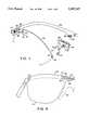
- FIG. 1is an exploded partial perspective rear view of a preferred aspect of the system of the invention.
- FIG. 2is an isometric rear view of an assembled lens set and frame of the preferred system.
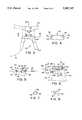
- FIG. 3is a partial front view of a preferred brow bar and nosebridge assembly (showing placement and position of partial lens).
- FIG. 4is a partial cross sectional plan view taken along line 4--4 of FIG. 3.
- FIG. 5is a partial cross sectional exploded side elevation taken along line 5--5 of FIG. 3.
- FIG. 6is a partial front elevation, partially exploded, of the nosebridge illustrated in FIG. 3, but without the brow bar or lens in place.
- FIG. 7is a cross sectional view taken along line 7--7 of FIG. 6.
- FIG. 8is a partial cross sectional view taken along line 8--8 of FIG. 6.
- FIG. 9is a partial rear elevation of the embodiment shown in FIG. 1, after snapping the lens in place, with added schematic detail of detent pin and spring (dotted line illustrates position of nosebridge).
- FIG. 10is an exploded partial rear isometric view of an alternate embodiment of the invention.
- FIGS. 11-13are rear elevations of various lens embodiments of the invention.
- FIG. 14is a partial rear elevation of an alternate embodiment of the invention.2
- FIG. 15is a partial cross sectional view taken along line 15--15 of FIG. 14.
- FIG. 16is a partial rear elevation of an alternate embodiment of the invention.
- Preferred sunglasses for use in the present inventionare those eyewear having toric lenses and substantial wrap depth such as those described in U.S. Pat. No. 4,741,611 to Burns and U.S. Pat. No. Des. 270,165 to Burns. Other preferred sunglasses have spherical lenses. These sport performance and fashion sunglasses are commercially available under the trademark GARGOYLES. The disclosures of these patents are hereby expressly incorporated by reference.
- the inventioncontemplates that any preferred shape or curvature of lens, such as "spherical” will employ a curved brow bar having generally the same curvature, at least at the points along which the lens and brow bar will be in contact.
- the "brow bar" from of frame setis preferred because it is capable of adaptation to a wider range of lens shapes and curvatures than a more complex frame would be.
- FIG. 1is an exploded partial perspective rear view of lens 10 (also shown in FIG. 11) aligned for sliding engagement and disengagement along the line indicated by arrow 15 with stud 31 as the first step in attaching, and the last step in detaching, lens 10 to brow bar 40.
- Nook 21which will engage the post 34 of stud 35 so that lens 10 is under stud head 33, has downwardly sloping edge 26 so lens 10 does not hang up on, or otherwise interfere with, nosebridge 50 during attachment and detachment of lens 10 to brow bar 40 at stud 31.
- Stud 31is shown in a preferred location near hinge 41.
- Lens 10also has notch 22 having notch ramp surface 27 to accommodate detent pin 62 (shown as dotted line)in nosebridge 50.
- Nosebridge 50is removably attached to brow bar 40 by screw 51 passing through an aperture in nosebridge 50 and into a threaded aperture 46 in key 45.
- lens 10is secured on stud 31 at a stud/nook pivotal attachment point, lens 10 is pivoted upwardly in the direction shown by arrow 16 to attach to brow bar and nosebridge via detent pin 62, and pivoted downwardly in the reverse direction of arrow 16 to remove the lens.
- FIG. 2is an isometric rear view of an assembled eyeglass lens set and frame 1 of the preferred system partially shown in FIG. 1.
- Front positioned lens stay bar 56is partially visible (shown in dotted line) through right lens 10.
- FIG. 9is a partial rear elevation of the embodiment shown in FIG. 1, after snapping lens 10 in place, showing schematic placement of detent pin 62 and spring 61.
- a dotted lineillustrates schematically where the nosebridge containing the pins and spring would be if present.
- Pin 62is generally free to move, against the resistance of spring 61, in the direction shown by arrow 63 so that notch 22 may alternately be engaged and disengaged with pin 62. Slight direct downward force on lens 10 just above notch 22 causes ramp 27 of notch 22 and pin 62 to cooperate to push pin 62 back against spring 61 in the direction of arrow 63 to release the lens from the pin.
- FIGS. 3-8show details of a preferred nosebridge for use with the embodiment shown in FIG. 1.
- FIG. 3is a partial front view of a preferred brow bar 40 and nosebridge 50 assembly (showing placement and position of partial lens 10).
- Nosebridge 50has a generally rear flange 54 on either side and front positioned lens stay bar 56 to from therebetween a lens receiving channel 55 (see FIG. 4).
- FIG. 5is a partial cross sectional exploded side elevation taken along line 5--5 of FIG. 3 showing assembly of brow bar 40, nosebridge 50 and screw 51.
- Screw 51is preferably countersunk in countersink 57.
- Key 45fits snugly into keyway 52 to prevent rotation of the brow bar and nosebridge with respect to one another.
- boss 44fits snugly into hollow 58 to augment the same purpose.
- Inner bridge face 48 of brow bar 40encloses channel 59 in nosebridge 50.
- FIG. 6is a partial front elevation, partially exploded, of the nosebridge 50 illustrated in FIG. 3, but without the brow bar or lens in place, the better to illustrate the shape of hollow 58 and the working of pin channel 59 and the detent pin/spring mechanism.
- Channel 59runs the width of nosebridge 50 between flanges 54 so that spring loaded pins 62 protrude somewhat into the lens channel partially defined by the flanges 54.
- Pins 62are restrained from exiting channel 59 by narrowings or collars 65 at or near either end of channel 59.
- Pins 62have corresponding shoulders 64 for engaging collars 65 to prevent pin expulsion from the channel and to set optimal pin projection into lens channel 55, as will appreciated by those skilled in the art.
- Pin endsare radiused.
- Pin bosses 67engage the ends of spring 61 to inhibit spring loss when brow bar 40 is removed, and for positive engagement of pins with the spring.
- Front surface of hollow 58is generally flat for smooth jointure of boss 44 into nosebridge 50, where face 48 serves as cover plate for spring channel 59.
- the "top" surface 66 of pin 62(that is the surface of pin 62 touching face 48) is generally flat, to better promote easy and unrestricted sliding of the pin over face 48.
- FIG. 10is an exploded partial rear isometric view of an alternate embodiment of the invention where a pair of generally semicircular notches in lens 14 engage a flanged key 32 at the temple side of the brow bar and a tang 53 at the nosebridge.
- Tang 53is preferably made of relatively resilient material and projects from the body of nosebridge 50 to engage notch 22 by initially deflecting before lens 14 as lens 14 is moved into place during the lens-mounting process, then returning to its original position and configuration within notch 22 as lens 14 moves into its final installed position.
- tang 53may be made of a relatively rigid material and project from the body of nosebridge 50 onto flange 54 or into channel 55 to engage notch 22 when nosebridge 50 is removably attached to brow bar 40 with screw 51 through aperture 47 in brow bar 40 and into threaded aperture 46 in the nosebridge.
- FIGS. 12 and 13are rear elevations of various other lens embodiments of the invention.
- Lens 11has angular shaped notch 22 and indentation 23.
- Lens 12has rounded angular notch 22 and smoother indentation 23.
- Lens 12optionally has aperture 25 for receiving a screw 35 to hold lens 12 to brow bar 40, instead of or in addition to other concavities on the lens edge (see FIG. 14).
- FIGS. 14-16are partial rear elevations of alternate embodiments of the invention.
- Lens 11is removably fastened to brow bar 40 by means of studs 31 and notch 22 and indentation 23 (screw 35 is optional and/or alternative).
- studs 31may be slidable (mechanism not shown, but a variant of the pin and spring mechanism above illustrated will serve if installed in brow bar under the stud) to the left and/or right, with or without resistance to some spring tension (such as for example in conventional sliding brief case latches).
- a slidable studwould accommodate different concavity spacings on a variety of lenses, in addition to providing an alternate releasable fastener mechanism.
- FIG. 15shows details of stud 31 and engagement of lens 11 under stud head 33 and around stud post 34.
- lens 13has snap fitting optimized recess 24 for releasable engagement with the post 34 of stud 31 along the directions indicated by arrow 17.
- lensesare comprised of conventional molded hardcoated polycarbonate lens material and have spherical curvature.
- Brow bar and studsare comprised of a conventional alloy of nickel/silver. Screws are preferably stainless steel.
- the nosebridgeis presently a molded acetate or propionate polymer material, but it is anticipated that a molded NYLON or other polyamide material will be preferred.
Landscapes
- Physics & Mathematics (AREA)
- Health & Medical Sciences (AREA)
- General Physics & Mathematics (AREA)
- Ophthalmology & Optometry (AREA)
- Optics & Photonics (AREA)
- Eyeglasses (AREA)
Abstract
Description
Claims (2)
Priority Applications (1)
| Application Number | Priority Date | Filing Date | Title |
|---|---|---|---|
| US08/482,291US5587747A (en) | 1994-03-22 | 1995-06-07 | Interchangeable eyeglass lens system |
Applications Claiming Priority (2)
| Application Number | Priority Date | Filing Date | Title |
|---|---|---|---|
| US08/216,528US5515116A (en) | 1994-03-22 | 1994-03-22 | Removable eyeglass nosebridge |
| US08/482,291US5587747A (en) | 1994-03-22 | 1995-06-07 | Interchangeable eyeglass lens system |
Related Parent Applications (1)
| Application Number | Title | Priority Date | Filing Date |
|---|---|---|---|
| US08/216,528Continuation-In-PartUS5515116A (en) | 1994-03-22 | 1994-03-22 | Removable eyeglass nosebridge |
Publications (1)
| Publication Number | Publication Date |
|---|---|
| US5587747Atrue US5587747A (en) | 1996-12-24 |
Family
ID=22807405
Family Applications (2)
| Application Number | Title | Priority Date | Filing Date |
|---|---|---|---|
| US08/216,528Expired - Fee RelatedUS5515116A (en) | 1994-03-22 | 1994-03-22 | Removable eyeglass nosebridge |
| US08/482,291Expired - LifetimeUS5587747A (en) | 1994-03-22 | 1995-06-07 | Interchangeable eyeglass lens system |
Family Applications Before (1)
| Application Number | Title | Priority Date | Filing Date |
|---|---|---|---|
| US08/216,528Expired - Fee RelatedUS5515116A (en) | 1994-03-22 | 1994-03-22 | Removable eyeglass nosebridge |
Country Status (3)
| Country | Link |
|---|---|
| US (2) | US5515116A (en) |
| AU (1) | AU2193495A (en) |
| WO (1) | WO1995025982A1 (en) |
Cited By (42)
| Publication number | Priority date | Publication date | Assignee | Title |
|---|---|---|---|---|
| USD400231S (en) | 1997-10-16 | 1998-10-27 | Bausch & Lomb Incorporated | Eyewear |
| US5880806A (en)* | 1997-10-16 | 1999-03-09 | Bausch & Lomb Incorporated | Eyewear frame construction |
| WO1999025279A1 (en)* | 1997-11-13 | 1999-05-27 | Etablissements Bolle S.N.C. | Sport glasses |
| US6074059A (en)* | 1998-03-30 | 2000-06-13 | Glass; Theodore A. | Sunglasses with removable lenses |
| DE19902986A1 (en)* | 1999-01-26 | 2000-08-10 | Joachim Stopfer | Spectacles with exchange lenses has exchange effected without aid of auxiliary device and lenses dismantled only by pressure against spring |
| US6428165B1 (en) | 2001-09-07 | 2002-08-06 | John C. Rivera | Interchangeable lens eyeglass system with interchangeable nosepiece |
| WO2003014806A1 (en)* | 2001-07-16 | 2003-02-20 | Sunreeve Co., Ltd. | Spectacles and spectacles set |
| US20030038820A1 (en)* | 2001-08-22 | 2003-02-27 | Purpura William J. | Method and apparatus for providing visual security for computer displays |
| US6533412B1 (en) | 2002-07-22 | 2003-03-18 | Navajo Manufacturing Company, Inc. | Interchangeable eyeglass lens system and method |
| US6592220B1 (en) | 2002-01-30 | 2003-07-15 | Lak Cheong | Eyeglass frame with removably mounted lenses |
| US6732383B2 (en) | 2001-12-03 | 2004-05-11 | The Burton Corporation | Goggle with side arm for wearing with a helmet |
| US20040130673A1 (en)* | 2000-10-25 | 2004-07-08 | Pierre Bassahon | Spectacles with interchangeable lenses |
| US20050036101A1 (en)* | 2003-08-14 | 2005-02-17 | Bacou-Dalloz Eye & Face Protection, Inc. | Safety glasses with flexible frame and interchangeable dual-lenses |
| US20050243270A1 (en)* | 1998-11-02 | 2005-11-03 | Zelman Gary M | Removable lens mounted to an eyewear platform |
| US7070272B1 (en)* | 2005-02-18 | 2006-07-04 | Hsiao-Chien Lu | Detachable eyeglass frame and aviator lens arrangement |
| US20080137028A1 (en)* | 2006-12-06 | 2008-06-12 | Bell Sports, Inc. | Partially Entrapped Frame Having a Removable Lens |
| US20100085533A1 (en)* | 2008-07-03 | 2010-04-08 | Oakley, Inc. | Floating lens mounting system |
| USD636009S1 (en) | 2010-10-15 | 2011-04-12 | Marvin James Hunt | Clip on monocles |
| US8192015B2 (en) | 2009-01-09 | 2012-06-05 | Oakley, Inc. | Eyeglass with enhanced ballistic resistance |
| US8210676B1 (en) | 2009-09-21 | 2012-07-03 | Marvin James Hunt | Sportsman's reading glasses |
| US8469510B2 (en) | 2009-01-09 | 2013-06-25 | Oakley, Inc. | Eyewear with enhanced ballistic resistance |
| US20130293829A1 (en)* | 2012-05-02 | 2013-11-07 | Lin Yun Chen | Assembly of frame and lens for glasses |
| US8661562B2 (en) | 2010-03-19 | 2014-03-04 | Oakley, Inc. | Eyewear with rigid lens support |
| US8668330B2 (en) | 2010-08-13 | 2014-03-11 | Oakley, Inc. | Eyewear with lens retention mechanism |
| WO2014082101A1 (en)* | 2012-11-07 | 2014-05-30 | Eye Ojo Corporation | Eyeglass frames having removable lens |
| US8992009B2 (en) | 2010-05-26 | 2015-03-31 | Francis William Austin | Module eye glasses |
| US20150092151A1 (en)* | 2013-09-27 | 2015-04-02 | Chih Ming Wu | Eyeglasses able to instantly install or remove lens |
| US9122078B2 (en) | 2011-12-01 | 2015-09-01 | Oakley, Inc. | Releasable earstem mounting mechanism for eyewear |
| EP2819401A4 (en)* | 2012-02-22 | 2015-10-07 | Sony Corp | Display device |
| US9188792B2 (en) | 2011-09-22 | 2015-11-17 | Oakley, Inc. | Mounting mechanism for eyewear |
| US9709817B2 (en) | 2015-12-07 | 2017-07-18 | Oakley, Inc. | Eyewear retention devices and methods |
| US9717631B2 (en) | 2012-08-31 | 2017-08-01 | Oakley, Inc. | Eyewear having multiple ventilation states |
| US20180017807A1 (en)* | 2015-02-03 | 2018-01-18 | Beta Group Llc | Eyeglass Assemblies |
| US10156734B2 (en) | 2015-12-08 | 2018-12-18 | Oakley, Inc. | Eyewear traction devices and methods |
| US10274748B2 (en) | 2014-03-27 | 2019-04-30 | Oakley, Inc. | Mounting mechanism for eyewear |
| US10359642B2 (en) | 2016-04-22 | 2019-07-23 | Oakley, Inc. | Mounting mechanism for eyewear |
| US10357400B2 (en) | 2012-12-11 | 2019-07-23 | Oakley, Inc. | Eyewear with outriggers |
| US10687981B2 (en) | 2015-10-09 | 2020-06-23 | Oakley, Inc. | Headworn supports with passive venting and removable lens |
| US10925772B2 (en) | 2013-03-07 | 2021-02-23 | Oakley, Inc. | Regeneratable anti-fogging element for goggle |
| US11029531B2 (en) | 2019-02-18 | 2021-06-08 | Amanda Carrier | Eyeglass frame lens lock |
| US20220334407A1 (en)* | 2021-04-16 | 2022-10-20 | Tsair Yuarn Industrial Co., Ltd. | Eyeglasses with hidden bridge |
| EP4345532A1 (en)* | 2022-09-27 | 2024-04-03 | Metrex Research LLC | Lens holding device |
Families Citing this family (13)
| Publication number | Priority date | Publication date | Assignee | Title |
|---|---|---|---|---|
| US5997137A (en)* | 1998-08-12 | 1999-12-07 | The Hilsinger Company Lp | Modular eyewear assembly |
| DE10034068A1 (en)* | 2000-03-23 | 2001-12-20 | Babak Nazerzadeh | Spectacles have a fitting having a male mold fixed by a manually operated stopping mechanism to prevent movement from the female mold |
| FR2815726A1 (en)* | 2000-10-25 | 2002-04-26 | Lebas Sports | Frame for spectacles has curved upper frames to hold interchangeable lenses |
| FR2857466A1 (en)* | 2002-02-19 | 2005-01-14 | Georges Bouvier | Spectacle, has frame with stud to receive helical spring that is compressed by moving glass after receiving stub to guide another stub with respect to engagement zone, and released to permit holding of latter stub by zone |
| DE20208262U1 (en)* | 2002-05-28 | 2002-10-24 | e.b.m. design-exklusive brillenmode GmbH, 94036 Passau | Glasses with interchangeable glasses |
| DE102007011306B4 (en)* | 2007-03-06 | 2009-12-10 | Müller, Manfred | Glasses, in particular sports and shooting glasses |
| US7524055B2 (en)* | 2007-03-19 | 2009-04-28 | Nike, Inc. | Eyewear with lens and interlocking nosepiece and frame |
| WO2011000166A1 (en)* | 2009-07-03 | 2011-01-06 | Chen Tsung-Wen | Spectacles convenient for changing lenses |
| US8201939B2 (en) | 2009-07-30 | 2012-06-19 | Nike, Inc. | Eyewear with frame and rear plate |
| JP6221223B2 (en)* | 2012-11-16 | 2017-11-01 | セイコーエプソン株式会社 | Optical member and virtual image display device |
| US9188797B2 (en)* | 2013-09-18 | 2015-11-17 | Benoit M. Rattelade | Eyeglass system and method of engagement |
| JP2015069044A (en)* | 2013-09-30 | 2015-04-13 | ▲呉▼ 志民WU,Chih Ming | Glasses frame and glasses using the same |
| US20230393416A1 (en)* | 2022-06-06 | 2023-12-07 | Prohero Group Co., Ltd | Eyeglasses |
Citations (17)
| Publication number | Priority date | Publication date | Assignee | Title |
|---|---|---|---|---|
| US2099748A (en)* | 1936-04-27 | 1937-11-23 | Mertens Paul | Eyeglass frame |
| US2240725A (en)* | 1938-06-16 | 1941-05-06 | American Optical Corp | Ophthalmic mounting |
| US2444498A (en)* | 1945-04-11 | 1948-07-06 | Polaroid Corp | Goggle with detachable lens |
| CA452108A (en)* | 1948-10-26 | Leslie Lessar Harry | Spectacles | |
| US2519852A (en)* | 1946-03-21 | 1950-08-22 | Francis M Blakeney | Ophthalmic mounting |
| DE899281C (en)* | 1951-02-17 | 1953-12-10 | Marwitz & Hauser Optische Fabr | Rimless glasses frame |
| GB747422A (en)* | 1953-07-22 | 1956-04-04 | Ronald Robinson Day | Improvements relating to spectacles |
| US2778270A (en)* | 1953-03-26 | 1957-01-22 | Pomerance Hy | Ophthalmic mounting |
| US3233250A (en)* | 1963-07-16 | 1966-02-08 | Renauld International Inc | Ski shield |
| US3708224A (en)* | 1971-05-24 | 1973-01-02 | Textron Inc | Ventilated goggles |
| US3709587A (en)* | 1971-03-10 | 1973-01-09 | M Wick | Eyeglasses having readily removable lenses |
| US4176921A (en)* | 1977-06-03 | 1979-12-04 | Carrera International Corporation | Eyeglasses having removable lenses |
| US4515448A (en)* | 1983-03-28 | 1985-05-07 | Oakley, Inc. | Sunglasses |
| US4824233A (en)* | 1985-01-11 | 1989-04-25 | Jannard James H | Multi-component sunglasses |
| US4834523A (en)* | 1987-03-17 | 1989-05-30 | Optyl Eyewear Fashion International Corporation | Eyeglasses with separable rims |
| US4951322A (en)* | 1989-09-27 | 1990-08-28 | Lin David J T | Detachable mono-glass sports goggles |
| US5293185A (en)* | 1992-09-17 | 1994-03-08 | Berger Ray A | Eyeglass frame permitting interchanging of lenses |
Family Cites Families (10)
| Publication number | Priority date | Publication date | Assignee | Title |
|---|---|---|---|---|
| US2208103A (en)* | 1937-08-21 | 1940-07-16 | Katherine K Paterson | Glasses |
| US2513214A (en)* | 1947-09-06 | 1950-06-27 | Bausch & Lomb | Semirimless spectacle |
| US3845525A (en)* | 1974-01-22 | 1974-11-05 | Koch & Sons Inc H | Survival kit connection to harness |
| FR2509058A1 (en)* | 1981-07-02 | 1983-01-07 | Essilor Int | MOUNT OF EYEWEAR WITH SOFT LINKS |
| FR2550353B1 (en)* | 1983-08-05 | 1985-10-11 | Essilor Int | NASAL EQUIPMENT FOR EYEWEAR MOUNTING AND CORRESPONDING EYEWEAR MOUNTING |
| US4749622A (en)* | 1986-03-31 | 1988-06-07 | Shell Oil Company | Structure coating method with asphaltic compositions |
| US4810080A (en)* | 1987-09-03 | 1989-03-07 | American Optical Corporation | Protective eyewear with removable nosepiece and corrective spectacle |
| IT221164Z2 (en)* | 1990-03-16 | 1994-02-16 | Finduck Srl | ATTACHMENT FOR HANDLES AND SHOULDER BAGS, BAGS, SUITCASES OR OTHER TRAVEL COUNTERS. |
| ATE121202T1 (en)* | 1991-08-30 | 1995-04-15 | Winter Optik | GLASSES WITH PADDING ON THE END OF THE TEMPLE OR ON THE NOSE PAD. |
| US5467148A (en)* | 1993-11-08 | 1995-11-14 | Bausch & Lomb Incorporated | Eyewear having interchangeable lenses |
- 1994
- 1994-03-22USUS08/216,528patent/US5515116A/ennot_activeExpired - Fee Related
- 1995
- 1995-03-22WOPCT/US1995/003679patent/WO1995025982A1/enactiveApplication Filing
- 1995-03-22AUAU21934/95Apatent/AU2193495A/ennot_activeAbandoned
- 1995-06-07USUS08/482,291patent/US5587747A/ennot_activeExpired - Lifetime
Patent Citations (17)
| Publication number | Priority date | Publication date | Assignee | Title |
|---|---|---|---|---|
| CA452108A (en)* | 1948-10-26 | Leslie Lessar Harry | Spectacles | |
| US2099748A (en)* | 1936-04-27 | 1937-11-23 | Mertens Paul | Eyeglass frame |
| US2240725A (en)* | 1938-06-16 | 1941-05-06 | American Optical Corp | Ophthalmic mounting |
| US2444498A (en)* | 1945-04-11 | 1948-07-06 | Polaroid Corp | Goggle with detachable lens |
| US2519852A (en)* | 1946-03-21 | 1950-08-22 | Francis M Blakeney | Ophthalmic mounting |
| DE899281C (en)* | 1951-02-17 | 1953-12-10 | Marwitz & Hauser Optische Fabr | Rimless glasses frame |
| US2778270A (en)* | 1953-03-26 | 1957-01-22 | Pomerance Hy | Ophthalmic mounting |
| GB747422A (en)* | 1953-07-22 | 1956-04-04 | Ronald Robinson Day | Improvements relating to spectacles |
| US3233250A (en)* | 1963-07-16 | 1966-02-08 | Renauld International Inc | Ski shield |
| US3709587A (en)* | 1971-03-10 | 1973-01-09 | M Wick | Eyeglasses having readily removable lenses |
| US3708224A (en)* | 1971-05-24 | 1973-01-02 | Textron Inc | Ventilated goggles |
| US4176921A (en)* | 1977-06-03 | 1979-12-04 | Carrera International Corporation | Eyeglasses having removable lenses |
| US4515448A (en)* | 1983-03-28 | 1985-05-07 | Oakley, Inc. | Sunglasses |
| US4824233A (en)* | 1985-01-11 | 1989-04-25 | Jannard James H | Multi-component sunglasses |
| US4834523A (en)* | 1987-03-17 | 1989-05-30 | Optyl Eyewear Fashion International Corporation | Eyeglasses with separable rims |
| US4951322A (en)* | 1989-09-27 | 1990-08-28 | Lin David J T | Detachable mono-glass sports goggles |
| US5293185A (en)* | 1992-09-17 | 1994-03-08 | Berger Ray A | Eyeglass frame permitting interchanging of lenses |
Cited By (62)
| Publication number | Priority date | Publication date | Assignee | Title |
|---|---|---|---|---|
| US5880806A (en)* | 1997-10-16 | 1999-03-09 | Bausch & Lomb Incorporated | Eyewear frame construction |
| USD400231S (en) | 1997-10-16 | 1998-10-27 | Bausch & Lomb Incorporated | Eyewear |
| WO1999025279A1 (en)* | 1997-11-13 | 1999-05-27 | Etablissements Bolle S.N.C. | Sport glasses |
| US6074059A (en)* | 1998-03-30 | 2000-06-13 | Glass; Theodore A. | Sunglasses with removable lenses |
| US20050243270A1 (en)* | 1998-11-02 | 2005-11-03 | Zelman Gary M | Removable lens mounted to an eyewear platform |
| DE19902986A1 (en)* | 1999-01-26 | 2000-08-10 | Joachim Stopfer | Spectacles with exchange lenses has exchange effected without aid of auxiliary device and lenses dismantled only by pressure against spring |
| US20040130673A1 (en)* | 2000-10-25 | 2004-07-08 | Pierre Bassahon | Spectacles with interchangeable lenses |
| US6926404B2 (en)* | 2000-10-25 | 2005-08-09 | Owoay | Spectacles with interchangeable lenses |
| WO2003014806A1 (en)* | 2001-07-16 | 2003-02-20 | Sunreeve Co., Ltd. | Spectacles and spectacles set |
| US20030038820A1 (en)* | 2001-08-22 | 2003-02-27 | Purpura William J. | Method and apparatus for providing visual security for computer displays |
| US6786592B2 (en) | 2001-09-07 | 2004-09-07 | John C. Rivera | Interchangeable lens eyeglass system with interchangeable nosepiece |
| US6709099B2 (en) | 2001-09-07 | 2004-03-23 | John C. Rivera | Method of assembling an interchangeable lens eyeglass system with bifocal segment |
| US20030048407A1 (en)* | 2001-09-07 | 2003-03-13 | Rivera John C. | Interchangeable lens eyeglass system with interchangeable nosepiece |
| US6428165B1 (en) | 2001-09-07 | 2002-08-06 | John C. Rivera | Interchangeable lens eyeglass system with interchangeable nosepiece |
| US6732383B2 (en) | 2001-12-03 | 2004-05-11 | The Burton Corporation | Goggle with side arm for wearing with a helmet |
| US6592220B1 (en) | 2002-01-30 | 2003-07-15 | Lak Cheong | Eyeglass frame with removably mounted lenses |
| US6533412B1 (en) | 2002-07-22 | 2003-03-18 | Navajo Manufacturing Company, Inc. | Interchangeable eyeglass lens system and method |
| US20050036101A1 (en)* | 2003-08-14 | 2005-02-17 | Bacou-Dalloz Eye & Face Protection, Inc. | Safety glasses with flexible frame and interchangeable dual-lenses |
| US6969172B2 (en) | 2003-08-14 | 2005-11-29 | Bacou-Dalloz Eye & Face Protection, Inc. | Safety glasses with flexible frame and interchangeable dual-lenses |
| US7070272B1 (en)* | 2005-02-18 | 2006-07-04 | Hsiao-Chien Lu | Detachable eyeglass frame and aviator lens arrangement |
| US7497569B2 (en)* | 2006-12-06 | 2009-03-03 | Bell Sports, Inc. | Partially entrapped frame having a removable lens |
| US20080137028A1 (en)* | 2006-12-06 | 2008-06-12 | Bell Sports, Inc. | Partially Entrapped Frame Having a Removable Lens |
| US20100085533A1 (en)* | 2008-07-03 | 2010-04-08 | Oakley, Inc. | Floating lens mounting system |
| US8911076B2 (en) | 2008-07-03 | 2014-12-16 | Oakley, Inc. | Floating lens mounting system |
| US7954942B2 (en) | 2008-07-03 | 2011-06-07 | Oakley, Inc. | Floating lens mounting system |
| US8408695B2 (en) | 2008-07-03 | 2013-04-02 | Oakley, Inc. | Floating lens mounting system |
| US8192015B2 (en) | 2009-01-09 | 2012-06-05 | Oakley, Inc. | Eyeglass with enhanced ballistic resistance |
| US8469510B2 (en) | 2009-01-09 | 2013-06-25 | Oakley, Inc. | Eyewear with enhanced ballistic resistance |
| US8534830B2 (en) | 2009-01-09 | 2013-09-17 | Oakley, Inc. | Eyeglass with enhanced ballistic resistance |
| US8746877B2 (en) | 2009-01-09 | 2014-06-10 | Oakley, Inc. | Eyewear with enhanced ballistic resistance |
| US8210676B1 (en) | 2009-09-21 | 2012-07-03 | Marvin James Hunt | Sportsman's reading glasses |
| US8661562B2 (en) | 2010-03-19 | 2014-03-04 | Oakley, Inc. | Eyewear with rigid lens support |
| US8800067B2 (en) | 2010-03-19 | 2014-08-12 | Oakley, Inc. | Eyewear with interchangeable lens mechanism |
| US8850626B2 (en) | 2010-03-19 | 2014-10-07 | Oakley, Inc. | Eyewear with enhanced pressure distribution |
| US8881316B2 (en) | 2010-03-19 | 2014-11-11 | Oakley, Inc. | Eyewear with rigid lens support |
| US8992009B2 (en) | 2010-05-26 | 2015-03-31 | Francis William Austin | Module eye glasses |
| US8668330B2 (en) | 2010-08-13 | 2014-03-11 | Oakley, Inc. | Eyewear with lens retention mechanism |
| USD636009S1 (en) | 2010-10-15 | 2011-04-12 | Marvin James Hunt | Clip on monocles |
| US9188792B2 (en) | 2011-09-22 | 2015-11-17 | Oakley, Inc. | Mounting mechanism for eyewear |
| US9122078B2 (en) | 2011-12-01 | 2015-09-01 | Oakley, Inc. | Releasable earstem mounting mechanism for eyewear |
| EP2819401A4 (en)* | 2012-02-22 | 2015-10-07 | Sony Corp | Display device |
| CN104115489B (en)* | 2012-02-22 | 2017-11-03 | 索尼公司 | Display device |
| US8702232B2 (en)* | 2012-05-02 | 2014-04-22 | Lin Yun Chen | Assembly of frame and lens for glasses |
| US20130293829A1 (en)* | 2012-05-02 | 2013-11-07 | Lin Yun Chen | Assembly of frame and lens for glasses |
| US9717631B2 (en) | 2012-08-31 | 2017-08-01 | Oakley, Inc. | Eyewear having multiple ventilation states |
| US10335317B2 (en) | 2012-08-31 | 2019-07-02 | Oakley, Inc. | Eyewear having multiple ventilation states |
| WO2014082101A1 (en)* | 2012-11-07 | 2014-05-30 | Eye Ojo Corporation | Eyeglass frames having removable lens |
| US10357400B2 (en) | 2012-12-11 | 2019-07-23 | Oakley, Inc. | Eyewear with outriggers |
| US10925772B2 (en) | 2013-03-07 | 2021-02-23 | Oakley, Inc. | Regeneratable anti-fogging element for goggle |
| US9223150B2 (en)* | 2013-09-27 | 2015-12-29 | Chih Ming Wu | Eyeglasses able to instantly install or remove lens |
| US20150092151A1 (en)* | 2013-09-27 | 2015-04-02 | Chih Ming Wu | Eyeglasses able to instantly install or remove lens |
| US10274748B2 (en) | 2014-03-27 | 2019-04-30 | Oakley, Inc. | Mounting mechanism for eyewear |
| US20180017807A1 (en)* | 2015-02-03 | 2018-01-18 | Beta Group Llc | Eyeglass Assemblies |
| US10687981B2 (en) | 2015-10-09 | 2020-06-23 | Oakley, Inc. | Headworn supports with passive venting and removable lens |
| US12239579B2 (en) | 2015-10-09 | 2025-03-04 | Oakley, Inc. | Headworn supports with passive venting and removable lens |
| US9709817B2 (en) | 2015-12-07 | 2017-07-18 | Oakley, Inc. | Eyewear retention devices and methods |
| US10156734B2 (en) | 2015-12-08 | 2018-12-18 | Oakley, Inc. | Eyewear traction devices and methods |
| US10359642B2 (en) | 2016-04-22 | 2019-07-23 | Oakley, Inc. | Mounting mechanism for eyewear |
| US11029531B2 (en) | 2019-02-18 | 2021-06-08 | Amanda Carrier | Eyeglass frame lens lock |
| US12066693B2 (en) | 2019-02-18 | 2024-08-20 | Amanda Carrier | Eyeglass frame lens lock |
| US20220334407A1 (en)* | 2021-04-16 | 2022-10-20 | Tsair Yuarn Industrial Co., Ltd. | Eyeglasses with hidden bridge |
| EP4345532A1 (en)* | 2022-09-27 | 2024-04-03 | Metrex Research LLC | Lens holding device |
Also Published As
| Publication number | Publication date |
|---|---|
| WO1995025982A1 (en) | 1995-09-28 |
| AU2193495A (en) | 1995-10-09 |
| US5515116A (en) | 1996-05-07 |
Similar Documents
| Publication | Publication Date | Title |
|---|---|---|
| US5587747A (en) | Interchangeable eyeglass lens system | |
| US5418581A (en) | Hinge system for eyewear | |
| US5467148A (en) | Eyewear having interchangeable lenses | |
| US7931365B2 (en) | Replaceable-lens eyewear and kit | |
| US7004580B2 (en) | Adjustable and reconfigurable eyeglasses | |
| US7347544B1 (en) | Hingeless eyeglasses as collar or headband | |
| JP4827012B2 (en) | Removable sunglasses | |
| JPS62269926A (en) | Lens exchangeable protection glasses | |
| US5418580A (en) | Interchangeable lens eyeglasses with pivoting temple release mechanism | |
| GB1530691A (en) | Spectacle structure | |
| US5056906A (en) | Prescription lens attachment for sunglasses | |
| US20210364820A1 (en) | Interchangeable Eyewear | |
| US4534627A (en) | Sunglasses pivotally mounted on browbar of spectacle frame | |
| US6227665B1 (en) | Sport eyeglasses having removable lenses | |
| US20070115424A1 (en) | Prescription insert for safety eyewear and conversion kit to make a presciption insert into functional eyeglasses | |
| US5106178A (en) | Prescription lens holder for use with sunglasses | |
| KR102068289B1 (en) | Lens exchangeable glasser | |
| WO2007148650A1 (en) | Spectacles set | |
| CN217238537U (en) | Glasses hanging rope and glasses | |
| US6776481B2 (en) | Clip on visor | |
| JPH0125931Y2 (en) | ||
| CN216145032U (en) | Lightweight metal frame glasses | |
| JPH06175085A (en) | Spectacles | |
| JPS6217779Y2 (en) | ||
| JPS628023Y2 (en) |
Legal Events
| Date | Code | Title | Description |
|---|---|---|---|
| AS | Assignment | Owner name:GARGOYLES, INC., WASHINGTON Free format text:ASSIGNMENT OF ASSIGNORS INTEREST;ASSIGNOR:BERNHEISER, CHARLES A.;REEL/FRAME:008199/0061 Effective date:19961008 | |
| FEPP | Fee payment procedure | Free format text:PAT HOLDER CLAIMS SMALL ENTITY STATUS - SMALL BUSINESS (ORIGINAL EVENT CODE: SM02); ENTITY STATUS OF PATENT OWNER: SMALL ENTITY | |
| STCF | Information on status: patent grant | Free format text:PATENTED CASE | |
| REMI | Maintenance fee reminder mailed | ||
| FPAY | Fee payment | Year of fee payment:4 | |
| SULP | Surcharge for late payment | ||
| FEPP | Fee payment procedure | Free format text:PAYER NUMBER DE-ASSIGNED (ORIGINAL EVENT CODE: RMPN); ENTITY STATUS OF PATENT OWNER: SMALL ENTITY Free format text:PAYOR NUMBER ASSIGNED (ORIGINAL EVENT CODE: ASPN); ENTITY STATUS OF PATENT OWNER: SMALL ENTITY | |
| AS | Assignment | Owner name:U.S. BANK OF WASHINGTON, N.A., WASHINGTON Free format text:SECURITY INTEREST;ASSIGNOR:GARGOYLES, INC.;REEL/FRAME:014384/0691 Effective date:19970407 | |
| AS | Assignment | Owner name:U.S. BANK OF WASHINGTON, N.A., WASHINGTON Free format text:SECURITY AGREEMENT;ASSIGNOR:GARGOYLES, INC.;REEL/FRAME:014394/0136 Effective date:19980115 | |
| AS | Assignment | Owner name:FG PREMIUM BRANDS, INC., RHODE ISLAND Free format text:ASSIGNMENT OF ASSIGNORS INTEREST;ASSIGNORS:CODA-GARGOYLES, LLC;GARGOYLES, INC.;REEL/FRAME:014420/0758 Effective date:20031230 | |
| AS | Assignment | Owner name:CODA-GARGOYLES LLC, NEW YORK Free format text:NUNC PRO TUNC ASSIGNMENT OF SECURITY INTERESTS AND OF PATENTS AGREEMENT;ASSIGNOR:U.S. BANK OF WASHINGTON NATIONAL ASSOCIATION;REEL/FRAME:014580/0266 Effective date:20031230 | |
| AS | Assignment | Owner name:FG PREMIUM BRANDS, INC., RHODE ISLAND Free format text:RELEASE OF SECURITY INTERESTS;ASSIGNOR:CODA-GARGOYLES LLC;REEL/FRAME:014580/0411 Effective date:20031230 | |
| AS | Assignment | Owner name:QUANTUM OPTICS, INC., RHODE ISLAND Free format text:CHANGE OF NAME;ASSIGNOR:FG PREMIUM BRANDS, INC.;REEL/FRAME:014588/0074 Effective date:20040227 | |
| FPAY | Fee payment | Year of fee payment:8 | |
| AS | Assignment | Owner name:JPMORGAN CHASE BANK, N.A., AS FIRST LIEN COLLATERA Free format text:SECURITY AGREEMENT;ASSIGNOR:QUANTUM OPTICS, INC.;REEL/FRAME:017089/0925 Effective date:20051209 | |
| AS | Assignment | Owner name:WILMINGTON TRUST COMPANY, AS SECOND LIEN COLLATERA Free format text:SECURITY AGREEMENT;ASSIGNOR:QUANTUM OPTICS, INC.;REEL/FRAME:017097/0988 Effective date:20051209 | |
| AS | Assignment | Owner name:SUNTRUST BANK, AS ADMINISTRATIVE AGENT, GEORGIA Free format text:SECURITY AGREEMENT;ASSIGNOR:QUANTUM OPTICS, INC.;REEL/FRAME:020317/0769 Effective date:20071219 | |
| AS | Assignment | Owner name:QUANTUM OPTICS, INC., RHODE ISLAND Free format text:TERMINATION AND RELEASE OF SECURITY INTEREST IN PATENT RIGHTS;ASSIGNOR:WILMINGTON TRUST COMPANY, AS SECOND LIEN COLLATERAL AGENT;REEL/FRAME:020309/0095 Effective date:20071219 Owner name:QUANTUM OPTICS, INC., RHODE ISLAND Free format text:TERMINATION AND RELEASE OF SECURITY INTEREST IN PATENT RIGHTS;ASSIGNOR:JPMORGAN CHASE BANK, N.A., AS FIRST LIEN COLLATERAL AGENT;REEL/FRAME:020309/0083 Effective date:20071217 | |
| FPAY | Fee payment | Year of fee payment:12 | |
| AS | Assignment | Owner name:QUANTUM OPTICS, INC.,RHODE ISLAND Free format text:RELEASE OF SECURITY INTEREST IN PATENTS;ASSIGNOR:SUNTRUST BANK;REEL/FRAME:024091/0234 Effective date:20100312 |