US5586913A - S to B watthour meter socket adapter - Google Patents
S to B watthour meter socket adapterDownload PDFInfo
- Publication number
- US5586913A US5586913AUS08/371,015US37101595AUS5586913AUS 5586913 AUS5586913 AUS 5586913AUS 37101595 AUS37101595 AUS 37101595AUS 5586913 AUS5586913 AUS 5586913A
- Authority
- US
- United States
- Prior art keywords
- watthour meter
- socket adapter
- meter socket
- electrical
- housing
- Prior art date
- Legal status (The legal status is an assumption and is not a legal conclusion. Google has not performed a legal analysis and makes no representation as to the accuracy of the status listed.)
- Expired - Lifetime
Links
- 239000004020conductorSubstances0.000claimsabstractdescription136
- 238000005452bendingMethods0.000claims1
- 238000003780insertionMethods0.000abstractdescription3
- 230000037431insertionEffects0.000abstractdescription3
- 238000010276constructionMethods0.000description10
- 238000004519manufacturing processMethods0.000description4
- 238000010292electrical insulationMethods0.000description3
- 125000006850spacer groupChemical group0.000description3
- 238000010998test methodMethods0.000description3
- 239000012777electrically insulating materialSubstances0.000description2
- 239000000463materialSubstances0.000description2
- 230000013011matingEffects0.000description2
- 238000012986modificationMethods0.000description2
- 230000004048modificationEffects0.000description2
- 238000012360testing methodMethods0.000description2
- 229920002799BoPETPolymers0.000description1
- 239000005041Mylar™Substances0.000description1
- 229910000639Spring steelInorganic materials0.000description1
- HCHKCACWOHOZIP-UHFFFAOYSA-NZincChemical compound[Zn]HCHKCACWOHOZIP-UHFFFAOYSA-N0.000description1
- 230000000712assemblyEffects0.000description1
- 238000000429assemblyMethods0.000description1
- 230000006835compressionEffects0.000description1
- 238000007906compressionMethods0.000description1
- 230000007797corrosionEffects0.000description1
- 238000005260corrosionMethods0.000description1
- 230000007423decreaseEffects0.000description1
- 230000007812deficiencyEffects0.000description1
- 238000011161developmentMethods0.000description1
- 239000003063flame retardantSubstances0.000description1
- 238000009413insulationMethods0.000description1
- 238000005259measurementMethods0.000description1
- 230000007935neutral effectEffects0.000description1
- 239000004033plasticSubstances0.000description1
- 229920003023plasticPolymers0.000description1
- 239000004417polycarbonateSubstances0.000description1
- 229920000515polycarbonatePolymers0.000description1
- 239000004800polyvinyl chlorideSubstances0.000description1
- 229920000915polyvinyl chloridePolymers0.000description1
- 230000000717retained effectEffects0.000description1
- 239000007787solidSubstances0.000description1
- 239000011701zincSubstances0.000description1
- 229910052725zincInorganic materials0.000description1
Images


Classifications
- H—ELECTRICITY
- H02—GENERATION; CONVERSION OR DISTRIBUTION OF ELECTRIC POWER
- H02B—BOARDS, SUBSTATIONS OR SWITCHING ARRANGEMENTS FOR THE SUPPLY OR DISTRIBUTION OF ELECTRIC POWER
- H02B1/00—Frameworks, boards, panels, desks, casings; Details of substations or switching arrangements
- H02B1/015—Boards, panels, desks; Parts thereof or accessories therefor
- H02B1/03—Boards, panels, desks; Parts thereof or accessories therefor for energy meters
- H—ELECTRICITY
- H01—ELECTRIC ELEMENTS
- H01R—ELECTRICALLY-CONDUCTIVE CONNECTIONS; STRUCTURAL ASSOCIATIONS OF A PLURALITY OF MUTUALLY-INSULATED ELECTRICAL CONNECTING ELEMENTS; COUPLING DEVICES; CURRENT COLLECTORS
- H01R33/00—Coupling devices specially adapted for supporting apparatus and having one part acting as a holder providing support and electrical connection via a counterpart which is structurally associated with the apparatus, e.g. lamp holders; Separate parts thereof
- H01R33/94—Holders formed as intermediate parts for linking a counter-part to a coupling part
Definitions
- the present inventionrelates, in general, to electrical watthour meters and, more specifically to watthour meter socket adapters.
- watthour metersare commonly employed to measure electrical power consumption at a residential or commercial building establishment.
- a cabinetis typically mounted on an outside wall of the residence or building and contains a meter socket having pairs of line and load terminals which are connected to electric power line conductors extending from the utility power network and electric load conductors connected to the residential or building establishment power distribution network.
- the line and load terminalsare connected to blade terminals extending outward from the base of a watthour meter to complete an electric circuit through the watthour meter between the line and load terminals mounted in the socket for the measurement of electrical power consumption.
- a "B" type watthour meteris provided with a Plurality of rigid, generally tubular conductors which extend downward and outward from the meter housing and are insertable into and fixedly attachable to the terminals in the watthour meter socket.
- S-type, socket-type, plug-in watthour metershave replaced older A base bottom connected meters which were formed of a single piece housing in which the watthour meter was fixedly mounted along with compression terminals which provide connection to the utility power lines and the building load distribution network.
- An S-type watthour meteralso has outwardly extending blade terminals.
- solid tubular conductors preformed to the desired shapewere bolted directly to the watthour meter blade terminals as shown in FIG. 1.
- tubular conductorswere then inserted into circular or rectangular shaped openings in the watthour meter socket terminals and fastened in place to complete an electrical circuit with electric power line and load conductors which were also connected to the watthour meter socket terminals. Potential wires were then connected to the watthour meter and to terminals mounted on a plate attached to the tubular conductors.
- FIG. 3depicts the next development of an S to B watthour meter adapter.
- a CT rated adapteras shown, but the adapter could also have been constructed as a self-contained adapter.
- hollow tubular conductorswere crimped to stranded wire conductors.
- the stranded wire conductorswere in turn connected to jaw contacts fixedly mounted in a watthour meter socket adapter housing at standard mounting positions to receive the watthour meter blade terminals in a snap-in connection.
- Potential wires from potential jaw terminals mounted in the watthour meter socket adapter housingwere run to disconnect links on the front of a terminal block formed on the socket adapter housing.
- the tubular conductorspass through bores machined in an insulating block made polyvinyl chloride and extend downward from the annular rim of the socket adapter.
- a ground connect pinis mounted by means of a bracket on a back plate attached to the socket adapter housing. The pin is connected by a conductor to the ground jaw of the socket adapter and receives a plug-in connector not shown, which is in turn connected to ground in the watthour meter socket.
- the S to B watthour meter socket adapter shown in FIG. 3still had a high manufacturing cost due to the extensive labor required to connect each individual stranded wire conductor to a tubular conductor and to a jaw contact. Further, the stranded wire conductors provided only a limited current carrying capability. Special potential wires and extensive labor were also necessary to bring the potential wires out to the front of the terminal block to enable testing of the watthour meter. In addition, extra labor and cost are involved in mounting the ground pin externally from the adapter housing.
- an S to B watthour meter socket adapterwhich overcomes the above-described deficiencies in previously devised S to B watthour meter socket adapters. It would also be desirable to provide an S to B watthour meter socket adapter which has a higher current carrying capability than previously devised S to B type watthour meter socket adapters. It would also be desirable to provide an S to B watthour meter socket adapter which enables a watthour meter to be tested by standard meter test procedures without extensive labor or construction costs. Finally, it would be desirable to provide an S to B watthour meter socket adapter which has a lower manufacturing cost due to the complete construction and conductor connections of the watthour meter socket adapter by the socket adapter manufacturer.
- the present inventionis a watthour meter socket adapter particularly devised for use as an S to B socket adapter for mounting an S-type watthour meter in a B type watthour meter socket.
- the watthour meter socket adapter of the present inventionincludes a housing having a watthour meter receiving portion formed of a base and an annular side wall extending from the base and terminating in a watthour meter mounting flange.
- a plurality of rigid electrical conductorsare disposed within the housing. Each electrical conductor has first and second ends. An electrical contact is mounted on the first end of each electrical conductor for receiving a blade terminal of a watthour meter in a snap-in connection. The second end of each electrical conductor extends externally of the housing for electrical connection to a terminal mounted in a watthour meter socket.
- each electrical conductorhas a polygonal cross section, with a rectangular cross section being preferred. More preferably, each electrical conductor is formed with a generally rectangular cross section, bus-bar configuration along its entire length. The second ends of each conductor are stepped down from the nominal maximum dimension of the conductors to fit within the standard terminals in the watthour meter socket.
- An apertureis formed in the side wall of the housing, with the second ends of the electrical conductors passing through the aperture.
- An electrically insulating sleeveis mounted in the housing and has an end portion extending through the aperture in the side wall externally of the housing. Apertures are formed in the sleeve for receiving the second ends of individual electrical conductors therethrough.
- the positioning meanspreferably includes an electrically insulating plate mounted in the housing and spaced from the base to define a cavity between the base and the insulating plate in which the electrical conductors are non-attachedly disposed.
- a plurality of aperturesare formed in the insulating plate, with each aperture receiving an outer end portion of a contact of an electrical conductor therethrough.
- a hollow receptaclemay be formed on the insulating plate to surround each jaw contact.
- An aperture in each receptacleallows insertion of a watthour meter blade terminal into the jaw contact within each receptacle.
- a ground connect pinis mounted in and is disposed in electrical contact with one of the ground surge plates. An outer end of the pin is extends externally of the socket adapter housing for receiving a plug-on connector attached to ground in the meter socket.
- the watthour meter socket adapter of the present inventionprovides significant advantages over previously devised S to B watthour meter socket adapters.
- the present socket adapteruniquely enables the now standard S-type watthour meter to be mounted in a B-type watthour meter socket without modification to the watthour meter socket.
- the rigid, bus-bar type electrical conductors employed in the present watthour meter socket adapterprovide higher current carrying capacity as compared to previously devised S to B type watthour meter socket adapters due to the large cross section of each conductor extending from the stepped down second end which is sized to fit within the existing terminals in the watthour meter socket.
- the watthour meter socket adaptermay be manufactured less expensively than previously devised S to B watthour meter socket adapters since the extensive labor required to fixedly mount each conductor within the housing of the socket adapter and the close manufacturing tolerances associated therewith and/or the labor required to connect each conductor to the blade terminals of a watthour meter are reduced or eliminated. Since the conductors and jaw contacts freely float within the housing, the jaw contacts are self-alignable with the watthour meter blade terminals for a secure, even contact and a maximum current carrying capacity.
- the watthour meter socket adapter of the present inventionenables a watthour meter to be tested separate from the socket by use of standard test procedures. Finally, the mounting of the ground pin directly on one of the ground surge plates simplifies the insulation of the ground pin and eliminates the separate mounting bracket and ground conductor employed in prior art adapters.
- FIG. 1is a front elevational view of a first prior art S to B type watthour meter-socket conductor mounting arrangement
- FIG. 2is a front elevational view of a second prior art S to B watthour meter-socket conductor mounting arrangement
- FIG. 3is a front elevational view of a prior art S to B type watthour meter socket adapter
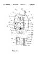
- FIG. 4is a perspective view of an S to B watthour meter socket adapter constructed in accordance with the teachings of the present invention
- FIG. 5is a front elevational view of the S to B watthour meter socket adapter shown in FIG. 4;
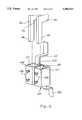
- FIG. 6is a cross sectional view generally taken along line 6--6 in FIG. 5;
- FIG. 7is a perspective view of an electrical conductor and jaw contact employed in the S to B watthour meter socket adapter shown in FIG. 5;
- FIG. 8is an enlarged, end elevational view of the jaw contact shown in FIG. 7;
- FIG. 9is a perspective view showing the mounting of a conductor of the present watthour meter socket adapter in a terminal in a "B" type watthour meter socket;
- FIG. 10is a partial, enlarged, perspective view of a shielding receptacle optionally formed on the insulating plate shown in FIGS. 4 and 5;
- FIG. 11is an exploded, perspective view showing the mounting of the present watthour meter socket adapter on a mounting plate in a watthour meter socket.
- the socket adapter 10is of generally conventional construction in that it includes a housing formed of a base 12 and a shell 14.
- the base 12 and shell 14are formed of an electrically insulating material, such as a suitable plastic, and may be constructed as a single piece, molded, unitary part, or as two separate pieces joined together by means of fasteners extending through the base 12 and the shell 14.
- the shell 14includes an annular side wall 18 which defines a watthour meter receiving aperture.
- a radially enlarged mounting flange 20is formed on an outer edge of the annular side wall 18 and forms a mounting surface for receiving a mating mounting flange on a watthour meter.
- a pair of ground surge plates 22are mounted in the shell 14.
- Each ground surge plate 22includes an inner depending leg 24 which extends along the annular side wall 18 of the shell 14.
- a fasteneris mounted through the leg 24 and the side wall 18 to attach the ground surge plate 22 to the shell 14.
- An upper end flange 26is disposed in registry with the mounting flange 20 on the shell 14.
- Ground conductors 28are electrically connected to each depending leg 24 of the ground surge plates 22 and to an internal ground connection within the housing 12 of the S to B watthour meter socket adapter 10 as described hereafter.
- the right ground conductor 28 in the orientation shown in FIGS. 4 and 5is attached to the mounting fastener extending through a central portion of the leg 24 of the right ground surge plate 22.
- the left ground conductor 28could also be connected to the fastener attaching the left ground surge plate 22 to the shell 14. However, in an exemplary embodiment, the left ground conductor 28 ends in a terminal through which a headed fastener 27 extends.
- the fastener 27extends through the side wall 18 of the shell 14 into a conductive pin 29 which extends outward through the side wall 18.
- the pin 29provides an external ground connection to a plug-type connector 31, FIG. 5, which is connected to ground in the watthour meter socket.
- the fastener 27is positioned such that the head of the fastener 27 or the terminal mounted on the end of the left ground conductor 28 and receiving the fastener 27 electrically contacts the left ground surge plate 22. As shown in FIGS. 4, 5 and 6, the head of the fastener 27 contacts the lower edge of the ground surge plate 22 to electrically connect the left ground conductor 28 to the left ground surge plate 22.
- the fastener 27could extend directly through the leg 24 of the left ground surge plate 22. In this configuration, the left ground conductor 28 could be connected to the fastener 27 or to the mounting fastener located centrally in the leg 24 of the left ground surge plate 22.
- a hanger 30is mounted to the base 12 by one of a plurality of fasteners 16 and provides a suitable attachment for mounting the socket adapter 10 in a watthour meter socket, as described hereafter.
- An aperture 32 having a generally arcuate shapeis formed at a bottom portion of the annular side wall 18 of the shell 14 adjacent to the base 12. The purpose of the aperture 32 will also be described in greater detail hereafter.
- each conductor 40is identically constructed, except for a slightly different preformed shape to provide appropriate routing and electrical insulation space between adjacent conductors within the socket adapter 10.
- each electrical conductor 40is in the form of a rigid electrical conductor, such as a bus bar.
- each conductor 40has a polygonal cross section, i.e., rectangular, square, etc., with a rectangular cross section being preferred and depicted in FIGS. 5-9 and 11.
- Each conductor 40is bent into predetermined angular sections, as shown in FIGS. 5 and 7, so as to be spaced from adjacent conductors 40 by a sufficient distance to prevent any flash or spark from passing therebetween. This eliminates the need for electrical insulation on the exterior of the bus bar type electrical conductors 40.
- exterior electrical insulationmay be utilized depending upon particular application requirements.
- Each conductor 40includes a first jaw contact end 42 and a second, opposed end 44 which is adapted to be inserted into electrical connection with a terminal mounted in a watthour meter socket.
- Each conductor 40is arranged in the socket adapter 10 with its longest dimension oriented in alignment with the longest cross sectional dimension of the blade terminals of a watthour meter which is attachable to the socket adapter 10. As shown in FIGS. 6, 7, 9 and 11 each conductor 40 is provided with a step or shoulder 46 which forms a stepped down, reduced cross section second end 44 which easily fits within one of the terminals in the watthour meter socket as shown in FIG. 9.
- Both terminals 149 and 150 fixedly mounted in a watthour meter socketare depicted in FIG. 9. Both terminals 149 and 150 have a rectangular or square through bore 151; although a circular bore is also employed in some watthour meter sockets.
- a preformed lead 152is mounted in the terminal 149 behind a contact plate 154 and connected to a stranded wire electrical line conductor by a conventional connector, not shown.
- a second lead 156is mounted in the terminal 150 behind a contact plate 154 and connected to an electrical load conductor, not shown.
- Two fasteners 158are threadable through apertures in one wall of each terminal 149 and 150 to securely connect the second end 44 of individual conductors 40 to the terminals 149 and 150.
- the smaller cross sectioned second end 44 of each conductor 40 extending from the step or shoulder 46is easily insertable into either terminal 149 or 150 regardless of whether the terminal 149 or 150 has a square, rectangular or circular bore 151.
- the larger cross section portion of the conductor 40 extending oppositely from the step or shoulder 46provides increased current carrying capability for the socket adapter 10 over prior art S to B socket adapters or socket arrangements described above.
- an insulating sleevedenoted generally by reference number 50 and shown in FIGS. 4, 5, 6 and 11, is mounted in the socket adapter 10 for covering exposed portions of the conductors 40 extending outward from the shell 14 of the socket adapter 10.
- the insulating sleeve 50is formed of a suitable electrically insulating material, such as mylar or, preferably, a fire retardant polycarbonate, and has opposed front and back walls 52 and 54 and opposed side walls 53 and 55 which are secured in position within the shell 14 by attachment to certain of the fasteners 16.
- One end of the front wall 52, the back wall 54 and the side walls 53 and 55are closed by an end wall 56.
- the end wall 56includes a plurality of spaced apertures 57, each of which receives the second end 44 of one of the conductors 40 therethrough.
- a jaw contact denoted generally by reference number 70is mounted on the first end 42 of each conductor 40.
- Each jaw contact 70is formed of first and second separate, contact clips 72 and 74 which are mounted on opposite sides of the major surfaces of the first end 42 of each conductor 40. As shown in FIGS. 7 and 8, each of the first and second contact clips 72 and 74 is formed with a first, generally planar, flat end portion 76 having at least one and preferably two apertures 78 formed therein. The apertures 78 are alienable with corresponding apertures formed in the first end 42 of each conductor 40.
- a first intermediate portion 80is formed on each contact clip, such as contact clip 74, and disposed at a predetermined angle from the end portion 76.
- the first intermediate portion 80is bent out of the plane containing the flat end portion 76 generally at an angle of approximately 15° with respect to the plane containing the end portion 76.
- a second intermediate portion 81is disposed at an angle of approximately 5° with respect to the plane containing the end portion 76.
- Each contact clip, such as contact clip 74terminates in an outer end portion 82 which is disposed at an angle substantially 15° or less with respect to a plane extending through a blade terminal contact point 84 formed between the end portion 82 and the intermediate portion 81 and lying generally parallel to the plane containing the end portion 76 of the contact clip 74.
- a slot 86is formed in each contact clip 72 and 74 and extends from the outer end portion 82 to a closed end approximate the flat end portion 76.
- the divides 86divide the end portion of each contact clip 72 and 74 into two finger-like contact portions.
- the biasing meanspreferably comprises first and second spring clips 90 and 92, respectively.
- One spring clip 90 or 92is provided for each contact clip 72 or 74, respectively.
- Each spring clip 90 and 92is formed of a suitable biasing material, such as SAE1060 spring steel, which is heat treated to 42-44Rc and then coated with a corrosion resistant material such as zinc.
- each spring clipsuch as spring clip 90
- each spring clipis formed with a flat, central portion 94.
- At least one and preferably a pair of apertures 96are formed through the juncture of the central portion 94 and an angled first end 95 and alienable with the apertures 78 in the contact clips 72 and 74 and the bores in the first end 42 of the conductor 40.
- Rivets 98are mountable through the aligned apertures to fixedly connect the spring clips 90 and 92 and the contact clips 72 and 74 to the first end 42 of each conductor 40.
- each spring clipsuch as spring clip 90
- the first end 95 of each spring clipis bent or otherwise formed at a predetermined angle from the central portion 94.
- the first end 95is initially formed at an angle of approximately 15° from the central portion 94.
- the central portion 94 of the spring clip 90will initially be spaced from the contact clip 72 until the rivet 98 forcibly urges and deforms the first end 95 of the spring clip 90 into engagement with the contact clip 72 bringing the central portion 94 of the spring clip 90 into registry with the flat end portion 76 of the contact clip 72. This increases the biasing force exerted on the first end 95 of the spring clip 90 and on the opposed spring clip 92 to form a secure connection between the contact clips 72 and 74 and the mating first end 42 of the conductor 40 inserted therebetween.
- Each spring clip 90 and 92further includes a second intermediate angled portion 100 which extends from an opposite end of the central portion 94.
- the second angled portion 100is also disposed at a predetermined angle from the plane containing the central portion 94. Preferably, this angle is substantially 15° from the plane containing the central portion 94.
- each spring clipsuch as spring clip 90, is formed with an angularly disposed second end portion 102 which is disposed at an angle of approximately 30° from the point 104 juncture of the second end portion 102 and the second angled portion 100. This juncture point 104 forms a contact point in which the spring clip 90 forcibly engages the contact clip 72.
- the mounting of the rivets 98 through the aligned apertures in the contact clips 72, 74, the spring clips 90, 92 and the first end 42 of the conductor 40deforms the spring clips 90 and 92 into forced engagement with the contact clips 72 and 74.
- Thisincreases the closure force urging the contact clips 72 and 74 together so as to enable the contact clips 72 and 74 to form a secure connection with a blade terminal of an electrical device, such as a watthour meter, inserted therebetween.
- jaw contacts 70Further, details concerning the construction and use of the jaw contacts 70 may be had by referring to copending U.S. patent applications, Ser. Nos. 08/215,915 and 08/216,261, the relevant portions of which are incorporated herein by reference.
- the positioning meansprimarily comprises an electrically insulating plate 110 shown in FIGS. 4, 5 and 6 which is attached to and spaced from the base 12 by the fasteners 16 and mounting posts 112 formed on and extending outward from the base 12 into the recess formed within the annular side wall 18 of the shell 14. As shown in FIG. 6, this spacing forms an interior cavity in which the conductors 40 are movably disposed. Apertures 111 are formed in the mounting plate 110 at the conventional jaw contact mounting positions and receive outer end portions of the jaw contacts 70 therethrough.
- the apertures 111positions the jaw contacts 70 at the standard position for receiving a blade terminal of a watthour meter therein as well as retaining the conductors 40 in position within the socket adapter 10. As noted above, the conductors 40 are also retained in the desired mounting position within the socket adapter 10 by the apertures 57 in the end wall 56 of the insulating sleeve 50.
- the conductors 40 and jaw contacts 70are non-attachedly mounted between the insulating plate 110 and the base 12. This enables the jaw contacts 70 to float or exhibit a slight amount of free movement within the apertures 111 in the insulating plate 110 for self-alignment with the blade terminals of a watthour meter. This reduces the cost of the present socket adapter 10 since less precise manufacturing tolerances need be achieved. However, it will be understood that the conductors 40 could also be individually fastened in place on the base 12.
- a separate apertureis also formed in the insulating plate 110 for receiving a ground jaw contact 114, as shown in FIGS. 4, 5 and 6.
- the ground jaw contact 114may have any suitable shape such as that shown in FIGS. 4, 5 and 6, or the shape shown in FIG. 30 of pending U.S. applications Ser. Nos. 08/215,915 and 08/216,261 already incorporated herein by reference.
- an aperture 116 formed substantially centrally in the mounting plate 110forms an opening through which the ground conductors 28 pass to an internal connection behind the insulating plate 110 to the ground jaw contact 114.
- the insulating plate 110also serves as a dead front as it covers the non-insulated conductors 40 and a substantial portion of the jaw contacts 70. This feature provides additional safety for the meter installer.
- a raised pocket or receptacle 120can be formed in and extending outwardly from the insulating plate 110 away from the base 12.
- the receptacle 120includes raised side walls 122 which terminate in an outer end 124.
- An aperture or slot 126is formed in the outer end 124, preferably with inwardly beveled edges 128.
- the interior of the receptacle 120is hollow to define a chamber for receiving and surrounding a jaw contact 70.
- the receptacle 120thus forms an electrically insulating shield around the jaw contact 70, with the narrow slot 126 provided access for a blade terminal of a watthour meter to be inserted into electrical connection with the jaw contact.
- two electrically insulating shields 117 and 119are loosely or fixedly disposed within the cavity between the insulating plate 110 and the base 12.
- the shield 117surrounds one upper disposed jaw contact 70 to insulate the jaw contact 70 and the attached first end 42 of the conductor 40 from the fastener 16 which is grounded.
- the other shield 119is disposed about one lower positioned jaw contact 70 and conductor 40 to electrically insulate two adjacent jaw contacts 70 and conductors 40 which are at two different phases.
- three pairs of conductors 40are mounted in the socket adapter 10.
- the three pairs of conductors 40provide standard L1, L2 and neutral single phase connections. It will be understood that additional conductors may be provided to form a three phase S to B type watthour meter socket adapter incorporating the features of the present invention.
- FIG. 11depicts the disconnected position of the watthour meter socket adapter 10 on a mounting plate 130 in a watthour meter socket.
- a mounting member 132such as a threaded screw, extends outward from the mounting plate 130 and engages the hanger 30 on the base 12 of the socket adapter 10 by insertion through aperture 134 in the hanger 30. In this position, the legs of the hanger 30 mount the top end of the base 12 of the socket adapter 10 flush against the mounting plate 130.
- spacer means 136such as a number of washers or a specific length spacer, are mounted about each lowermost fastener 16 between the head of each fastener 16 and the base 12.
- the number of washers or the length of the spaceris selected to enable the heads of the fasteners 16 to engage the mounting plate 130 of the socket adapter 10 and position the base 12 generally parallel to the mounting plate 130 so as to place the mounting flange 20 in registry with the edges of the aperture in the cover of the watthour meter socket to prevent any gap or space therebetween. This decreases the possibility of tampering with the watthour meter socket adapter 10 to unauthorizedly tap non-metered electric power from the watthour meter socket.
- the electrical conductors in the present watthour meter socket adapterfreely float within the socket adapter housing thereby eliminating any labor required to fixedly mount the conductors to the socket adapter housing as needed in previously devised S to B watthour meter socket constructions.
- the watthour meter socket adapter of the present inventionalso enables the now standard S-type plug-in watthour meter to be inserted in a B-type watthour meter socket.
- the S to B type watthour meter socket adapter of the present inventionis uniquely designed to enable a watthour meter to be tested separate from the watthour meter socket by standard test procedures. This eliminates the need for the extensive labor required with previously devised S to B type watthour meter socket assemblies to connect and bring out the watthour meter potential test terminals to a convenient location.
Landscapes
- Engineering & Computer Science (AREA)
- Power Engineering (AREA)
- Connector Housings Or Holding Contact Members (AREA)
Abstract
Description
Claims (32)
Priority Applications (1)
| Application Number | Priority Date | Filing Date | Title |
|---|---|---|---|
| US08/371,015US5586913A (en) | 1994-03-22 | 1995-01-11 | S to B watthour meter socket adapter |
Applications Claiming Priority (4)
| Application Number | Priority Date | Filing Date | Title |
|---|---|---|---|
| US21626194A | 1994-03-22 | 1994-03-22 | |
| US21591594A | 1994-03-22 | 1994-03-22 | |
| US08/334,562US5595506A (en) | 1994-11-04 | 1994-11-04 | S to B watthour meter socket adapter |
| US08/371,015US5586913A (en) | 1994-03-22 | 1995-01-11 | S to B watthour meter socket adapter |
Related Parent Applications (1)
| Application Number | Title | Priority Date | Filing Date |
|---|---|---|---|
| US08/334,562ContinuationUS5595506A (en) | 1994-03-22 | 1994-11-04 | S to B watthour meter socket adapter |
Publications (1)
| Publication Number | Publication Date |
|---|---|
| US5586913Atrue US5586913A (en) | 1996-12-24 |
Family
ID=23307789
Family Applications (2)
| Application Number | Title | Priority Date | Filing Date |
|---|---|---|---|
| US08/334,562Expired - LifetimeUS5595506A (en) | 1994-03-22 | 1994-11-04 | S to B watthour meter socket adapter |
| US08/371,015Expired - LifetimeUS5586913A (en) | 1994-03-22 | 1995-01-11 | S to B watthour meter socket adapter |
Family Applications Before (1)
| Application Number | Title | Priority Date | Filing Date |
|---|---|---|---|
| US08/334,562Expired - LifetimeUS5595506A (en) | 1994-03-22 | 1994-11-04 | S to B watthour meter socket adapter |
Country Status (1)
| Country | Link |
|---|---|
| US (2) | US5595506A (en) |
Cited By (21)
| Publication number | Priority date | Publication date | Assignee | Title |
|---|---|---|---|---|
| US5997347A (en)* | 1996-06-03 | 1999-12-07 | Ekstrom Industries, Inc. | Watthour meter socket adapter with snap-on jaw contacts |
| US6059605A (en)* | 1997-10-30 | 2000-05-09 | Ekstrom Industries, Inc. | Watthour meter socket adapter |
| US6104586A (en)* | 1997-11-20 | 2000-08-15 | Ekstrom Industries, Inc. | Circuit breaker switch apparatus |
| US6152764A (en)* | 1997-09-04 | 2000-11-28 | Ekstrom Industries, Inc. | Jaw blades for watthour meter socket adapter |
| US6325666B1 (en) | 1998-09-04 | 2001-12-04 | Ekstrom Industries, Inc. | Watthour meter socket adapter with safety shield |
| US6409537B2 (en) | 1999-06-07 | 2002-06-25 | Ekstrom Industries, Inc. | Watthour meter socket adapter with auxiliary component mounts |
| US6475028B1 (en) | 2000-04-06 | 2002-11-05 | Ekstrom Industries, Inc. | Meter socket adapter with connections to electrical component in an enclosure |
| US6478589B2 (en) | 2001-01-31 | 2002-11-12 | Ekstrom Industries, Inc. | Electrical service apparatus safety shield with wire guides |
| US6488535B1 (en) | 2000-04-06 | 2002-12-03 | Ekstrom Industries, Inc. | Meter socket adapter with connections to electrical component in an enclosure |
| US6689956B2 (en)* | 2002-04-05 | 2004-02-10 | Southwestern Battery Supply Company, Inc. | Electrical bus duct system with heat-dissipating enclosure |
| US20050122094A1 (en)* | 2003-10-03 | 2005-06-09 | Ekstrom Industries, Inc. | Modular watthour meter socket and test switch |
| US7182632B1 (en)* | 2003-06-06 | 2007-02-27 | Alpha Technologies, Inc. | Connection systems and methods for utility meters |
| US20090294260A1 (en)* | 2008-05-30 | 2009-12-03 | Itron,Inc. | Meter with integrated high current switch |
| US20110074600A1 (en)* | 2009-09-30 | 2011-03-31 | Itron, Inc. | Utility remote disconnect from a meter reading system |
| US20110074603A1 (en)* | 2009-09-30 | 2011-03-31 | Itron, Inc. | Safety utility reconnect |
| EP2264469A3 (en)* | 2003-12-16 | 2011-08-17 | Hager Electro GmbH & Co. KG | Connection system for electricity meters |
| US20120123711A1 (en)* | 2008-02-27 | 2012-05-17 | Asoka Usa Corporation | System and Method for Measuring Power Usage |
| US8493232B2 (en) | 2009-09-30 | 2013-07-23 | Itron, Inc. | Gas shut-off valve with feedback |
| US9005423B2 (en) | 2012-12-04 | 2015-04-14 | Itron, Inc. | Pipeline communications |
| US20170006723A1 (en)* | 2015-07-01 | 2017-01-05 | Honeywell International Inc. | Electricity meter forms module |
| US20220166176A1 (en)* | 2020-11-23 | 2022-05-26 | E.J. Brooks Company D.B.A. Brooks Utility Products Group | Watt-hour meter blade |
Families Citing this family (21)
| Publication number | Priority date | Publication date | Assignee | Title |
|---|---|---|---|---|
| EP2404350A2 (en) | 2009-03-03 | 2012-01-11 | Powergetics, Inc. | Meter socket connection methods and systems for local generators or monitoring connections |
| US8971057B2 (en) | 2009-03-25 | 2015-03-03 | Stem, Inc | Bidirectional energy converter with controllable filter stage |
| US8002578B2 (en)* | 2009-04-21 | 2011-08-23 | Ekstrom Industries, Inc. | Watthour meter socket lock adapter |
| WO2011008505A2 (en)* | 2009-06-29 | 2011-01-20 | Powergetics, Inc | High speed feedback adjustment of power charge/discharge from energy storage system |
| US8350521B2 (en) | 2009-06-29 | 2013-01-08 | Stem, Inc. | High speed feedback adjustment of power charge/discharge from an energy storage system |
| US8803570B2 (en) | 2011-12-29 | 2014-08-12 | Stem, Inc | Multiphase electrical power assignment at minimal loss |
| US8774977B2 (en) | 2011-12-29 | 2014-07-08 | Stem, Inc. | Multiphase electrical power construction and assignment at minimal loss |
| US8922192B2 (en) | 2011-12-30 | 2014-12-30 | Stem, Inc. | Multiphase electrical power phase identification |
| US9406094B2 (en) | 2012-08-14 | 2016-08-02 | Stem Inc. | Method and apparatus for delivering power using external data |
| US10782721B2 (en) | 2012-08-27 | 2020-09-22 | Stem, Inc. | Method and apparatus for balancing power on a per phase basis in multi-phase electrical load facilities using an energy storage system |
| US11454999B2 (en) | 2012-08-29 | 2022-09-27 | Stem, Inc. | Method and apparatus for automatically reconfiguring multi-phased networked energy storage devices at a site |
| US9634508B2 (en) | 2012-09-13 | 2017-04-25 | Stem, Inc. | Method for balancing frequency instability on an electric grid using networked distributed energy storage systems |
| US10389126B2 (en) | 2012-09-13 | 2019-08-20 | Stem, Inc. | Method and apparatus for damping power oscillations on an electrical grid using networked distributed energy storage systems |
| US10756543B2 (en) | 2012-09-13 | 2020-08-25 | Stem, Inc. | Method and apparatus for stabalizing power on an electrical grid using networked distributed energy storage systems |
| US10693294B2 (en) | 2012-09-26 | 2020-06-23 | Stem, Inc. | System for optimizing the charging of electric vehicles using networked distributed energy storage systems |
| DE102014014066B3 (en)* | 2014-09-29 | 2015-11-19 | Robert Seidl | Mounting aid for meter plug pins |
| CA2991218A1 (en)* | 2017-01-09 | 2018-07-09 | E.J. Brooks Company | Watthour meter block with safety shield |
| US10020627B1 (en)* | 2017-01-09 | 2018-07-10 | E.J. Brooks Company | Watthour meter block with safety shield |
| USD873689S1 (en) | 2017-01-09 | 2020-01-28 | E.J. Brooks Company | Watthour meter block with safety shield |
| US11894643B2 (en) | 2021-05-12 | 2024-02-06 | E.J. Brooks Company | Meter block adaptor and method |
| USD1008832S1 (en)* | 2021-06-10 | 2023-12-26 | E.J. Brooks Company | Meter block adaptor |
Citations (10)
| Publication number | Priority date | Publication date | Assignee | Title |
|---|---|---|---|---|
| US2030522A (en)* | 1933-03-30 | 1936-02-11 | Palmer Electric & Mfg Co | Test-block for electric meters |
| US3061763A (en)* | 1960-04-01 | 1962-10-30 | Kenneth A Ekstrom | Meter adapter |
| US3221216A (en)* | 1962-07-26 | 1965-11-30 | Murray Mfg Corp | Meter mount |
| US4117530A (en)* | 1977-06-30 | 1978-09-26 | Square D Company | Meter receptacle assembly |
| US5033973A (en)* | 1990-04-23 | 1991-07-23 | Ekstrom Industries, Inc. | Service disconnect and meter storage adapter |
| US5088004A (en)* | 1991-05-31 | 1992-02-11 | Schlumberger Canada, Ltd. | Electricity metering device with cover |
| US5145403A (en)* | 1991-06-26 | 1992-09-08 | Meter Devices Company, Inc. | Safety cover for meter socket |
| US5181166A (en)* | 1991-05-31 | 1993-01-19 | Schlumberger Canada Limited | Securing mechanism for an electricity metering device |
| US5207595A (en)* | 1992-01-28 | 1993-05-04 | Ekstrom Industries, Inc. | Watthour meter socket adapter with lockable terminal cover and sealing ring |
| USRE34531E (en)* | 1987-03-06 | 1994-02-01 | Ekstrom Industries, Inc. | Watthour meter socket adapter |
Family Cites Families (1)
| Publication number | Priority date | Publication date | Assignee | Title |
|---|---|---|---|---|
| US4892485A (en)* | 1988-06-16 | 1990-01-09 | Patton Victor L | Adapter plate for converting a three phase meter socket for use with a single phase watt hour meter |
- 1994
- 1994-11-04USUS08/334,562patent/US5595506A/ennot_activeExpired - Lifetime
- 1995
- 1995-01-11USUS08/371,015patent/US5586913A/ennot_activeExpired - Lifetime
Patent Citations (11)
| Publication number | Priority date | Publication date | Assignee | Title |
|---|---|---|---|---|
| US2030522A (en)* | 1933-03-30 | 1936-02-11 | Palmer Electric & Mfg Co | Test-block for electric meters |
| US3061763A (en)* | 1960-04-01 | 1962-10-30 | Kenneth A Ekstrom | Meter adapter |
| US3221216A (en)* | 1962-07-26 | 1965-11-30 | Murray Mfg Corp | Meter mount |
| US4117530A (en)* | 1977-06-30 | 1978-09-26 | Square D Company | Meter receptacle assembly |
| USRE34531E (en)* | 1987-03-06 | 1994-02-01 | Ekstrom Industries, Inc. | Watthour meter socket adapter |
| USRE34531F1 (en)* | 1987-03-06 | 1995-05-09 | Ekstroem Ind Inc | Watthour meter socket adapter |
| US5033973A (en)* | 1990-04-23 | 1991-07-23 | Ekstrom Industries, Inc. | Service disconnect and meter storage adapter |
| US5088004A (en)* | 1991-05-31 | 1992-02-11 | Schlumberger Canada, Ltd. | Electricity metering device with cover |
| US5181166A (en)* | 1991-05-31 | 1993-01-19 | Schlumberger Canada Limited | Securing mechanism for an electricity metering device |
| US5145403A (en)* | 1991-06-26 | 1992-09-08 | Meter Devices Company, Inc. | Safety cover for meter socket |
| US5207595A (en)* | 1992-01-28 | 1993-05-04 | Ekstrom Industries, Inc. | Watthour meter socket adapter with lockable terminal cover and sealing ring |
Non-Patent Citations (6)
| Title |
|---|
| Machine Design, Jan. 11, 1990, pp. 117 119, Automotive Technology.* |
| Machine Design, Jan. 11, 1990, pp. 117-119, Automotive Technology. |
| MDK, Die Miniatur Doppel Flachfeder Systeme Leaf Spring Connector Systems, Grote & Hartman (No Date Available).* |
| MDK, Die Miniatur-Doppel-Flachfeder-Systeme-Leaf Spring Connector Systems, Grote & Hartman (No Date Available). |
| Scientific Atlanta, Service Reconnect Device Series SRD S1900 Jan. 1992.* |
| Scientific Atlanta, Service Reconnect Device Series SRD-S1900 Jan. 1992. |
Cited By (35)
| Publication number | Priority date | Publication date | Assignee | Title |
|---|---|---|---|---|
| US5997347A (en)* | 1996-06-03 | 1999-12-07 | Ekstrom Industries, Inc. | Watthour meter socket adapter with snap-on jaw contacts |
| US6152764A (en)* | 1997-09-04 | 2000-11-28 | Ekstrom Industries, Inc. | Jaw blades for watthour meter socket adapter |
| US6059605A (en)* | 1997-10-30 | 2000-05-09 | Ekstrom Industries, Inc. | Watthour meter socket adapter |
| US6104586A (en)* | 1997-11-20 | 2000-08-15 | Ekstrom Industries, Inc. | Circuit breaker switch apparatus |
| US6325666B1 (en) | 1998-09-04 | 2001-12-04 | Ekstrom Industries, Inc. | Watthour meter socket adapter with safety shield |
| US6428350B1 (en) | 1999-06-07 | 2002-08-06 | Ekstrom Industries, Inc. | Watthour meter socket adapter with auxiliary component mounts |
| US6409537B2 (en) | 1999-06-07 | 2002-06-25 | Ekstrom Industries, Inc. | Watthour meter socket adapter with auxiliary component mounts |
| US6443761B1 (en) | 1999-06-07 | 2002-09-03 | Ekstrom Industries, Inc. | Watthour meter socket adapter with auxiliary component mounts |
| US6589072B2 (en) | 1999-06-07 | 2003-07-08 | Ekstrom Industries, Inc. | Watthour meter socket adapter with auxiliary component mounts |
| US6592399B2 (en) | 1999-06-07 | 2003-07-15 | Ekstrom Industries, Inc. | Watthour meter socket adapter with auxiliary component mounts |
| US6475028B1 (en) | 2000-04-06 | 2002-11-05 | Ekstrom Industries, Inc. | Meter socket adapter with connections to electrical component in an enclosure |
| US6488535B1 (en) | 2000-04-06 | 2002-12-03 | Ekstrom Industries, Inc. | Meter socket adapter with connections to electrical component in an enclosure |
| US6478589B2 (en) | 2001-01-31 | 2002-11-12 | Ekstrom Industries, Inc. | Electrical service apparatus safety shield with wire guides |
| US6644989B2 (en) | 2001-01-31 | 2003-11-11 | Ekstrom Industries, Inc. | Electrical service apparatus with light transmission guide |
| US6689956B2 (en)* | 2002-04-05 | 2004-02-10 | Southwestern Battery Supply Company, Inc. | Electrical bus duct system with heat-dissipating enclosure |
| US7182632B1 (en)* | 2003-06-06 | 2007-02-27 | Alpha Technologies, Inc. | Connection systems and methods for utility meters |
| US7189109B2 (en)* | 2003-10-03 | 2007-03-13 | Ekstrom Industries, Inc. | Modular watthour meter socket and test switch |
| US20050122094A1 (en)* | 2003-10-03 | 2005-06-09 | Ekstrom Industries, Inc. | Modular watthour meter socket and test switch |
| EP1544626B1 (en)* | 2003-12-16 | 2012-07-25 | Hager Electro GmbH & Co. KG | Connection system for electricity meters |
| EP2264469A3 (en)* | 2003-12-16 | 2011-08-17 | Hager Electro GmbH & Co. KG | Connection system for electricity meters |
| EP2264470A3 (en)* | 2003-12-16 | 2011-08-17 | Hager Electro GmbH & Co. KG | Connection system for electricity meters |
| US20120123711A1 (en)* | 2008-02-27 | 2012-05-17 | Asoka Usa Corporation | System and Method for Measuring Power Usage |
| US20090294260A1 (en)* | 2008-05-30 | 2009-12-03 | Itron,Inc. | Meter with integrated high current switch |
| US20090295371A1 (en)* | 2008-05-30 | 2009-12-03 | Itron, Inc. | Actuator/wedge improvements to embedded meter switch |
| US8395464B2 (en) | 2008-05-30 | 2013-03-12 | Itron, Inc. | Actuator/wedge improvements to embedded meter switch |
| US8040664B2 (en)* | 2008-05-30 | 2011-10-18 | Itron, Inc. | Meter with integrated high current switch |
| US20110074600A1 (en)* | 2009-09-30 | 2011-03-31 | Itron, Inc. | Utility remote disconnect from a meter reading system |
| US20110074603A1 (en)* | 2009-09-30 | 2011-03-31 | Itron, Inc. | Safety utility reconnect |
| US8493232B2 (en) | 2009-09-30 | 2013-07-23 | Itron, Inc. | Gas shut-off valve with feedback |
| US8890711B2 (en) | 2009-09-30 | 2014-11-18 | Itron, Inc. | Safety utility reconnect |
| US9005423B2 (en) | 2012-12-04 | 2015-04-14 | Itron, Inc. | Pipeline communications |
| US20170006723A1 (en)* | 2015-07-01 | 2017-01-05 | Honeywell International Inc. | Electricity meter forms module |
| US9921245B2 (en)* | 2015-07-01 | 2018-03-20 | Honeywell International Inc. | Electricity meter forms module |
| US10247757B2 (en) | 2015-07-01 | 2019-04-02 | Honeywell International Inc. | Electricity meter forms module |
| US20220166176A1 (en)* | 2020-11-23 | 2022-05-26 | E.J. Brooks Company D.B.A. Brooks Utility Products Group | Watt-hour meter blade |
Also Published As
| Publication number | Publication date |
|---|---|
| US5595506A (en) | 1997-01-21 |
Similar Documents
| Publication | Publication Date | Title |
|---|---|---|
| US5586913A (en) | S to B watthour meter socket adapter | |
| CA2305615C (en) | Watthour meter socket adapter | |
| US5571031A (en) | Watthour meter mounting apparatus with improved electrical connections | |
| CA2144210C (en) | Watthour meter mounting apparatus with safety shield | |
| CA2198650C (en) | Apparatus for grounding external metal watthour meter component | |
| US5620337A (en) | Fused watthour meter bypass storage adapter | |
| US5385486A (en) | Watthour meter socket adapter with additional plug-in terminal capability | |
| US5588874A (en) | Watthour meter socket adapter for replacing an OB watthour meter | |
| US5853300A (en) | Watthour socket adapter with improved electrical connections | |
| US8011937B2 (en) | Unitary member with multiple outlets having surge protection circuitry | |
| US6561844B1 (en) | Lug for providing both electrical and mechanical connection between buses and watt hour meter sockets | |
| US6247941B1 (en) | Combination electric connector having multiple grounding prong receiving portions and a plug unit secured by means of a plurality of hooks and coupling flanges | |
| US5546269A (en) | Metered electrical service tap | |
| US4772213A (en) | Watthour meter socket adapter | |
| US7234954B1 (en) | International electrical receptacle | |
| US6663422B1 (en) | Jaw blades and jaw blade couplers for watthour meter socket adapter | |
| US6152764A (en) | Jaw blades for watthour meter socket adapter | |
| US6325666B1 (en) | Watthour meter socket adapter with safety shield | |
| US7232335B2 (en) | K-series watthour meter socket adapter | |
| US4034290A (en) | Electrical meter assembly having displaced meter and socket terminals | |
| US4368943A (en) | Auxiliary equipment enclosure unit for watthour meter sockets | |
| US3458768A (en) | Electric meter-mounting and fuse-holder assembly | |
| CN106058510B (en) | Electrical verification ground interface fexible unit | |
| AU2011201640B2 (en) | S to A watthour meter socket adapter | |
| US8932088B2 (en) | Anti-turn mechanism for multiple connector sizes |
Legal Events
| Date | Code | Title | Description |
|---|---|---|---|
| AS | Assignment | Owner name:EKSTROM INDUSTRIES, INC., MICHIGAN Free format text:ASSIGNMENT OF ASSIGNORS INTEREST;ASSIGNORS:ROBINSON, DARRELL;LOEHR, KARL;PRUEHS, ALLEN V.;AND OTHERS;REEL/FRAME:007315/0434 Effective date:19950110 | |
| STCF | Information on status: patent grant | Free format text:PATENTED CASE | |
| FEPP | Fee payment procedure | Free format text:PAYOR NUMBER ASSIGNED (ORIGINAL EVENT CODE: ASPN); ENTITY STATUS OF PATENT OWNER: LARGE ENTITY | |
| FPAY | Fee payment | Year of fee payment:4 | |
| FPAY | Fee payment | Year of fee payment:8 | |
| FPAY | Fee payment | Year of fee payment:12 | |
| AS | Assignment | Owner name:WELLS FARGO BANK, NATIONAL ASSOCIATION, CALIFORNIA Free format text:SECURITY AGREEMENT;ASSIGNOR:EKSTROM, INC.;REEL/FRAME:023471/0837 Effective date:20091104 | |
| AS | Assignment | Owner name:WELLS FARGO BANK, NATIONAL ASSOCIATION, CALIFORNIA Free format text:CORRECTIVE ASSIGNMENT TO CORRECT THE NAME OF THE GRANTOR FROM EKSTROM, INC. TO EKSTROM INDUSTRIES, INC. PREVIOUSLY RECORDED ON REEL 023471 FRAME 0837;ASSIGNOR:EKSTROM INDUSTRIES, INC.;REEL/FRAME:023486/0512 Effective date:20091104 Owner name:WELLS FARGO BANK, NATIONAL ASSOCIATION, CALIFORNIA Free format text:CORRECTIVE ASSIGNMENT TO CORRECT THE NAME OF THE GRANTOR FROM EKSTROM, INC. TO EKSTROM INDUSTRIES, INC. PREVIOUSLY RECORDED ON REEL 023471 FRAME 0837. ASSIGNOR(S) HEREBY CONFIRMS THE CORRECT NAME OF THE GRANTOR IS EKSTROM INDUSTRIES, INC.;ASSIGNOR:EKSTROM INDUSTRIES, INC.;REEL/FRAME:023486/0512 Effective date:20091104 | |
| AS | Assignment | Owner name:E.J. BROOKS COMPANY (AS SUCCESSOR BY MERGER TO EKS Free format text:RELEASE OF PATENT COLLATERAL;ASSIGNOR:WELLS FARGO BANK, NATIONAL ASSOCIATION, AS AGENT;REEL/FRAME:038086/0888 Effective date:20160311 |